JP6512573B2 - シール部材 - Google Patents
シール部材 Download PDFInfo
- Publication number
- JP6512573B2 JP6512573B2 JP2014196772A JP2014196772A JP6512573B2 JP 6512573 B2 JP6512573 B2 JP 6512573B2 JP 2014196772 A JP2014196772 A JP 2014196772A JP 2014196772 A JP2014196772 A JP 2014196772A JP 6512573 B2 JP6512573 B2 JP 6512573B2
- Authority
- JP
- Japan
- Prior art keywords
- axial direction
- seal member
- combustion gas
- end surface
- opening
- Prior art date
- Legal status (The legal status is an assumption and is not a legal conclusion. Google has not performed a legal analysis and makes no representation as to the accuracy of the status listed.)
- Active
Links
- 239000000567 combustion gas Substances 0.000 claims description 90
- 238000001816 cooling Methods 0.000 claims description 72
- 238000011144 upstream manufacturing Methods 0.000 claims description 44
- 238000007789 sealing Methods 0.000 claims description 24
- 238000007599 discharging Methods 0.000 claims description 3
- 230000007704 transition Effects 0.000 description 28
- 238000012986 modification Methods 0.000 description 26
- 230000004048 modification Effects 0.000 description 26
- 239000007789 gas Substances 0.000 description 19
- 239000000446 fuel Substances 0.000 description 7
- 230000008646 thermal stress Effects 0.000 description 5
- 230000000903 blocking effect Effects 0.000 description 3
- 230000002093 peripheral effect Effects 0.000 description 3
- 238000003491 array Methods 0.000 description 2
- 238000002485 combustion reaction Methods 0.000 description 2
- 238000004891 communication Methods 0.000 description 2
- 239000012530 fluid Substances 0.000 description 2
- 238000007792 addition Methods 0.000 description 1
- 238000005452 bending Methods 0.000 description 1
- 230000006866 deterioration Effects 0.000 description 1
- 230000005484 gravity Effects 0.000 description 1
- 239000002184 metal Substances 0.000 description 1
- 238000000034 method Methods 0.000 description 1
- 238000006467 substitution reaction Methods 0.000 description 1
Images


Classifications
-
- F—MECHANICAL ENGINEERING; LIGHTING; HEATING; WEAPONS; BLASTING
- F01—MACHINES OR ENGINES IN GENERAL; ENGINE PLANTS IN GENERAL; STEAM ENGINES
- F01D—NON-POSITIVE DISPLACEMENT MACHINES OR ENGINES, e.g. STEAM TURBINES
- F01D11/00—Preventing or minimising internal leakage of working-fluid, e.g. between stages
- F01D11/005—Sealing means between non relatively rotating elements
- F01D11/006—Sealing the gap between rotor blades or blades and rotor
- F01D11/008—Sealing the gap between rotor blades or blades and rotor by spacer elements between the blades, e.g. independent interblade platforms
-
- F—MECHANICAL ENGINEERING; LIGHTING; HEATING; WEAPONS; BLASTING
- F01—MACHINES OR ENGINES IN GENERAL; ENGINE PLANTS IN GENERAL; STEAM ENGINES
- F01D—NON-POSITIVE DISPLACEMENT MACHINES OR ENGINES, e.g. STEAM TURBINES
- F01D11/00—Preventing or minimising internal leakage of working-fluid, e.g. between stages
- F01D11/005—Sealing means between non relatively rotating elements
-
- F—MECHANICAL ENGINEERING; LIGHTING; HEATING; WEAPONS; BLASTING
- F01—MACHINES OR ENGINES IN GENERAL; ENGINE PLANTS IN GENERAL; STEAM ENGINES
- F01D—NON-POSITIVE DISPLACEMENT MACHINES OR ENGINES, e.g. STEAM TURBINES
- F01D11/00—Preventing or minimising internal leakage of working-fluid, e.g. between stages
-
- F—MECHANICAL ENGINEERING; LIGHTING; HEATING; WEAPONS; BLASTING
- F01—MACHINES OR ENGINES IN GENERAL; ENGINE PLANTS IN GENERAL; STEAM ENGINES
- F01D—NON-POSITIVE DISPLACEMENT MACHINES OR ENGINES, e.g. STEAM TURBINES
- F01D25/00—Component parts, details, or accessories, not provided for in, or of interest apart from, other groups
- F01D25/08—Cooling; Heating; Heat-insulation
- F01D25/12—Cooling
-
- F—MECHANICAL ENGINEERING; LIGHTING; HEATING; WEAPONS; BLASTING
- F01—MACHINES OR ENGINES IN GENERAL; ENGINE PLANTS IN GENERAL; STEAM ENGINES
- F01D—NON-POSITIVE DISPLACEMENT MACHINES OR ENGINES, e.g. STEAM TURBINES
- F01D9/00—Stators
- F01D9/02—Nozzles; Nozzle boxes; Stator blades; Guide conduits, e.g. individual nozzles
- F01D9/023—Transition ducts between combustor cans and first stage of the turbine in gas-turbine engines; their cooling or sealings
-
- F—MECHANICAL ENGINEERING; LIGHTING; HEATING; WEAPONS; BLASTING
- F02—COMBUSTION ENGINES; HOT-GAS OR COMBUSTION-PRODUCT ENGINE PLANTS
- F02C—GAS-TURBINE PLANTS; AIR INTAKES FOR JET-PROPULSION PLANTS; CONTROLLING FUEL SUPPLY IN AIR-BREATHING JET-PROPULSION PLANTS
- F02C7/00—Features, components parts, details or accessories, not provided for in, or of interest apart form groups F02C1/00 - F02C6/00; Air intakes for jet-propulsion plants
- F02C7/12—Cooling of plants
- F02C7/16—Cooling of plants characterised by cooling medium
- F02C7/18—Cooling of plants characterised by cooling medium the medium being gaseous, e.g. air
-
- F—MECHANICAL ENGINEERING; LIGHTING; HEATING; WEAPONS; BLASTING
- F02—COMBUSTION ENGINES; HOT-GAS OR COMBUSTION-PRODUCT ENGINE PLANTS
- F02C—GAS-TURBINE PLANTS; AIR INTAKES FOR JET-PROPULSION PLANTS; CONTROLLING FUEL SUPPLY IN AIR-BREATHING JET-PROPULSION PLANTS
- F02C7/00—Features, components parts, details or accessories, not provided for in, or of interest apart form groups F02C1/00 - F02C6/00; Air intakes for jet-propulsion plants
- F02C7/28—Arrangement of seals
-
- F—MECHANICAL ENGINEERING; LIGHTING; HEATING; WEAPONS; BLASTING
- F16—ENGINEERING ELEMENTS AND UNITS; GENERAL MEASURES FOR PRODUCING AND MAINTAINING EFFECTIVE FUNCTIONING OF MACHINES OR INSTALLATIONS; THERMAL INSULATION IN GENERAL
- F16J—PISTONS; CYLINDERS; SEALINGS
- F16J15/00—Sealings
- F16J15/16—Sealings between relatively-moving surfaces
- F16J15/162—Special parts or details relating to lubrication or cooling of the sealing itself
-
- F—MECHANICAL ENGINEERING; LIGHTING; HEATING; WEAPONS; BLASTING
- F16—ENGINEERING ELEMENTS AND UNITS; GENERAL MEASURES FOR PRODUCING AND MAINTAINING EFFECTIVE FUNCTIONING OF MACHINES OR INSTALLATIONS; THERMAL INSULATION IN GENERAL
- F16J—PISTONS; CYLINDERS; SEALINGS
- F16J15/00—Sealings
- F16J15/44—Free-space packings
- F16J15/447—Labyrinth packings
- F16J15/4476—Labyrinth packings with radial path
Landscapes
- Engineering & Computer Science (AREA)
- General Engineering & Computer Science (AREA)
- Mechanical Engineering (AREA)
- Chemical & Material Sciences (AREA)
- Combustion & Propulsion (AREA)
- Turbine Rotor Nozzle Sealing (AREA)
- Sealing Using Fluids, Sealing Without Contact, And Removal Of Oil (AREA)
Description
本発明の第一の態様におけるシール部材は、ロータ軸の周りに配置される燃焼器と軸方向下流側に配置されて燃焼ガスの流れる燃焼ガス流路の一部を画定する静翼との間に設けられ、前記燃焼器と前記静翼との間をシールするシール部材であって、前記静翼の前記軸方向上流側を向く側端面に対向して前記軸方向下流側を向く端面と、前記ロータ軸を基準として周方向に並んで前記端面に複数設けられた開口から前記側端面に向かって冷却空気を排出する冷却流路と、前記開口が形成された端面よりも前記軸方向下流側に突出する隙間形成部と、が形成され、前記開口に隣接する領域には、前記ロータ軸を基準として径方向に窪むスリットが形成されている。
また、スリットによってシール部材の曲げ剛性を下げることができる。その結果、シール部材自体が撓みやすくなり、周方向の熱応力の分布によってシール部材の内部に生じる歪みを吸収することができる。これにより、シール部材の歪みを抑えることができ、冷却することによって生じる温度差の影響を低減することができる。
以下、本発明に係る第一実施形態について図1から図9を参照して説明する。
ガスタービン1は、図1に示すように、外気を圧縮して圧縮空気Aを生成する圧縮機10と、燃料を圧縮空気Aに混合して燃焼させて燃焼ガスGを生成する複数の燃焼器20と、燃焼ガスGにより駆動するタービン30と、燃焼器20とタービン30との間に配置されるシール部材7とを備えている。
また、径方向Drであって軸線Acから遠ざかる側を径方向Dr外側、その反対側を径方向Dr内側とする。
突出部424は、側端面461のガスパス面441から径方向Dr内側又は径方向Dr外側の離れた位置に形成されている。突出部424は、ロータ軸Arを中心とする円弧状に形成されている。
本実施形態のガスタービン1によれば、圧縮機10からの圧縮空気Aは、タービン30のケーシング31内の空間に入り、燃焼器20内に供給される。燃焼器20では、この圧縮空気Aと共に外部から供給される燃料を内筒22a内で燃焼して、燃焼ガスGが生成される。燃焼ガスGは、尾筒21を介してタービン30の燃焼ガス流路Pgに流入する。この燃焼ガスGは、燃焼ガス流路Pgを通る過程で、動翼本体37に接して、タービンロータ33をロータ軸Ar回りに回転させる。
本変形例は、第一実施形態と比較して、シール部材7の隙間形成部廻りの構造が異なっている。その他の構成は、第一実施形態と同様である。以下、図8及び図9を参照して、第一実施形態と異なる構造に限定して、本変形例を以下に説明する。なお、図8は、スリット83を含んだ面でシール部材7を周方向に見た断面図であり、図9におけるIX−IX断面を示す。図9は、図8におけるVIII−VIII断面を示す。また、以下で説明するシール部材7は、内側シール部材7aを対象とした説明であるが、外側シール部材7bについても同様の考え方が適用できる。
図10を参照しながら、本発明の第二実施形態について以下に説明する。
第二実施形態では、第一実施形態と比較して、シール部材を燃焼ガス流路Pgに面して配置して、隙間形成部を含めたシール部材の構造を変えている点が異なっている。図10は、本実施形態におけるシール部材廻りの要部拡大図である。
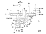
本変形例は、第二実施形態に適用されるシール部材の変形例を示すものである。第二実施形態の変形例のシール部材の隙間形成部廻りの構造は、第一実施形態の変形例と基本的には同じ構造である。図12及び図13を用いて、第二実施形態の変形例のシール部材9を説明するが、本変形例においても、内側シール部材9aについて以下に説明する。外側シール部材9bについても、同様の考え方が適用できる。なお、図12はシール部材9の周方向Dcから見た断面を示し、図13は軸方向Da下流側から上流側を見た端面91aの断面(図12のX−X断面)を示す。
A 圧縮空気
10 圧縮機
20 燃焼器
Ac 軸線
Da 軸方向
21 尾筒
210 出口フランジ
210a 周方向フランジ部
211 後端部
22 燃料供給器
22a 内筒
30 タービン
Dc 周方向
Dr 径方向
31 ケーシング
Ar ロータ軸
33 タービンロータ
34 ロータ本体
35 動翼列
36 動翼
37 動翼本体
38 プラットフォーム
39 翼根
40 静翼列
41 静翼
42 静翼本体
43 外側シュラウド
45 内側シュラウド
40a 第一静翼列
41a 第一静翼
421 前縁部
44 シュラウド本体
441 ガスパス面
46 側壁
461 側端面
424 突出部
50 翼環
52 遮熱環
60 分割環
G 燃焼ガス
Pg 燃焼ガス流路
7、9 シール部材
C キャビティ
70、90 本体部
71、91 第一凸部
71a、91a 端面
71b、71c、91b、91c 隙間形成部
72、92 第二凸部
721、921 接触シール部材
721a 第一シール面
73、93 第三凸部
74、94 第四凸部
70a、90a 第二シール面
80、100 冷却流路
80a、100a 開口
801 軸方向流路
802 径方向流路
80b、100b 流入口
81 第一係合部
82 第二係合部
83 スリット
83a スリット底部
Claims (5)
- ロータ軸の周りに配置される燃焼器と軸方向下流側に配置されて燃焼ガスの流れる燃焼ガス流路の一部を画定する静翼との間に設けられ、前記燃焼器と前記静翼との間をシールするシール部材であって、
前記静翼の前記軸方向上流側を向く側端面に対向して前記軸方向下流側を向く端面と、
前記ロータ軸を基準として周方向に並んで前記端面に複数設けられた開口から前記側端面に向かって冷却空気を排出する冷却流路と、
前記開口が形成された端面よりも前記軸方向下流側に突出する隙間形成部と、が形成され、
前記開口に隣接する領域には、前記ロータ軸を基準として径方向に窪むスリットが形成されているシール部材。 - 前記燃焼ガス流路よりも外側に配置されている請求項1に記載のシール部材。
- 前記冷却流路は、前記静翼の前記軸方向上流側を向く前縁部に対して、前記軸方向上流側の対向する位置を含んで、前記周方向の一定の領域に形成されている請求項1または2に記載のシール部材。
- 前記隙間形成部は、前記開口に対して前記周方向に隣接して配置されている請求項1に記載のシール部材。
- 前記軸方向上流側で前記燃焼器に接続する第一係合部と、
前記軸方向下流側で前記静翼の前記側端面から前記軸方向上流側に延びる環状の突出部に接続する第二係合部と、を備え、
前記第二係合部は、前記突出部との間に形成される環状のシール面を有し、
前記スリットは、前記燃焼ガス流路側から径方向に窪み、
前記スリットの前記燃焼ガス流路に対して外側に形成された端部は、前記シール面が形成された位置より前記燃焼ガス流路側に近い位置に配置されている請求項1〜4のいずれか一項に記載されたシール部材。
Priority Applications (6)
| Application Number | Priority Date | Filing Date | Title |
|---|---|---|---|
| JP2014196772A JP6512573B2 (ja) | 2014-09-26 | 2014-09-26 | シール部材 |
| US15/512,760 US10724392B2 (en) | 2014-09-26 | 2015-09-08 | Seal member |
| DE112015004378.0T DE112015004378B4 (de) | 2014-09-26 | 2015-09-08 | Dichtungselement |
| KR1020177007680A KR101939508B1 (ko) | 2014-09-26 | 2015-09-08 | 시일 부재 |
| CN201580050889.7A CN107076028B (zh) | 2014-09-26 | 2015-09-08 | 密封构件 |
| PCT/JP2015/075439 WO2016047432A1 (ja) | 2014-09-26 | 2015-09-08 | シール部材 |
Applications Claiming Priority (1)
| Application Number | Priority Date | Filing Date | Title |
|---|---|---|---|
| JP2014196772A JP6512573B2 (ja) | 2014-09-26 | 2014-09-26 | シール部材 |
Publications (3)
| Publication Number | Publication Date |
|---|---|
| JP2016070082A JP2016070082A (ja) | 2016-05-09 |
| JP2016070082A5 JP2016070082A5 (ja) | 2017-08-31 |
| JP6512573B2 true JP6512573B2 (ja) | 2019-05-15 |
Family
ID=55580960
Family Applications (1)
| Application Number | Title | Priority Date | Filing Date |
|---|---|---|---|
| JP2014196772A Active JP6512573B2 (ja) | 2014-09-26 | 2014-09-26 | シール部材 |
Country Status (6)
| Country | Link |
|---|---|
| US (1) | US10724392B2 (ja) |
| JP (1) | JP6512573B2 (ja) |
| KR (1) | KR101939508B1 (ja) |
| CN (1) | CN107076028B (ja) |
| DE (1) | DE112015004378B4 (ja) |
| WO (1) | WO2016047432A1 (ja) |
Families Citing this family (7)
| Publication number | Priority date | Publication date | Assignee | Title |
|---|---|---|---|---|
| JP7214332B2 (ja) * | 2017-01-18 | 2023-01-30 | ゼネラル・エレクトリック・カンパニイ | ガスタービンの燃焼システムにおける段階的な燃料および空気噴射 |
| FR3064029B1 (fr) * | 2017-03-15 | 2021-04-30 | Safran Aircraft Engines | Joint d’etancheite air-feu et assemblage comprenant un tel joint |
| FR3081511B1 (fr) * | 2018-05-28 | 2020-06-05 | Safran Aircraft Engines | Dispositif d'etancheite entre deux parois annulaires d'un moteur d'aeronef |
| JP7451108B2 (ja) * | 2019-08-16 | 2024-03-18 | 三菱重工業株式会社 | 静翼、及びこれを備えているガスタービン |
| US11619174B2 (en) | 2020-02-14 | 2023-04-04 | Raytheon Technologies Corporation | Combustor to vane sealing assembly and method of forming same |
| CN116710702B (zh) * | 2021-03-09 | 2026-02-27 | 三菱重工业株式会社 | 密封构件及燃气轮机 |
| US12529324B2 (en) * | 2022-01-06 | 2026-01-20 | Mitsubishi Heavy Industries, Ltd. | Turbine static blade, fitting structure, and gas turbine |
Family Cites Families (12)
| Publication number | Priority date | Publication date | Assignee | Title |
|---|---|---|---|---|
| US4502809A (en) * | 1981-08-31 | 1985-03-05 | Carrier Corporation | Method and apparatus for controlling thermal growth |
| JP4031590B2 (ja) * | 1999-03-08 | 2008-01-09 | 三菱重工業株式会社 | 燃焼器の尾筒シール構造及びその構造を用いたガスタービン |
| JP2001289003A (ja) * | 2000-04-04 | 2001-10-19 | Mitsubishi Heavy Ind Ltd | ガスタービンの冷却構造 |
| US6675584B1 (en) | 2002-08-15 | 2004-01-13 | Power Systems Mfg, Llc | Coated seal article used in turbine engines |
| US6860108B2 (en) | 2003-01-22 | 2005-03-01 | Mitsubishi Heavy Industries, Ltd. | Gas turbine tail tube seal and gas turbine using the same |
| JP4381276B2 (ja) * | 2004-10-08 | 2009-12-09 | 三菱重工業株式会社 | ガスタービン |
| GB0515868D0 (en) | 2005-08-02 | 2005-09-07 | Rolls Royce Plc | Cooling arrangement |
| US7797948B2 (en) * | 2007-03-27 | 2010-09-21 | Siemens Energy, Inc. | Transition-to-turbine seal apparatus and transition-to-turbine seal junction of a gas turbine engine |
| JP2009167905A (ja) | 2008-01-16 | 2009-07-30 | Mitsubishi Heavy Ind Ltd | ガスタービン燃焼器出口シール構造 |
| FR2937098B1 (fr) * | 2008-10-15 | 2015-11-20 | Snecma | Etancheite entre une chambre de combustion et un distributeur de turbine dans une turbomachine |
| JP5925030B2 (ja) | 2012-04-17 | 2016-05-25 | 三菱重工業株式会社 | ガスタービン、及びその高温部品 |
| JP6016655B2 (ja) | 2013-02-04 | 2016-10-26 | 三菱日立パワーシステムズ株式会社 | ガスタービン尾筒シール及びガスタービン |
-
2014
- 2014-09-26 JP JP2014196772A patent/JP6512573B2/ja active Active
-
2015
- 2015-09-08 KR KR1020177007680A patent/KR101939508B1/ko active Active
- 2015-09-08 CN CN201580050889.7A patent/CN107076028B/zh active Active
- 2015-09-08 DE DE112015004378.0T patent/DE112015004378B4/de active Active
- 2015-09-08 WO PCT/JP2015/075439 patent/WO2016047432A1/ja not_active Ceased
- 2015-09-08 US US15/512,760 patent/US10724392B2/en active Active
Also Published As
| Publication number | Publication date |
|---|---|
| DE112015004378T5 (de) | 2017-06-14 |
| CN107076028B (zh) | 2019-06-04 |
| KR20170043641A (ko) | 2017-04-21 |
| DE112015004378B4 (de) | 2023-03-02 |
| WO2016047432A1 (ja) | 2016-03-31 |
| CN107076028A (zh) | 2017-08-18 |
| KR101939508B1 (ko) | 2019-01-16 |
| US20170292397A1 (en) | 2017-10-12 |
| US10724392B2 (en) | 2020-07-28 |
| JP2016070082A (ja) | 2016-05-09 |
Similar Documents
| Publication | Publication Date | Title |
|---|---|---|
| JP6512573B2 (ja) | シール部材 | |
| KR101852290B1 (ko) | 터빈 정익, 터빈, 및 터빈 정익의 개조 방법 | |
| US8277177B2 (en) | Fluidic rim seal system for turbine engines | |
| US8075256B2 (en) | Ingestion resistant seal assembly | |
| US9518478B2 (en) | Microchannel exhaust for cooling and/or purging gas turbine segment gaps | |
| US8118548B2 (en) | Shroud for a turbomachine | |
| JP6366180B2 (ja) | シール構造 | |
| US10443437B2 (en) | Interwoven near surface cooled channels for cooled structures | |
| US9017013B2 (en) | Gas turbine engine with improved cooling between turbine rotor disk elements | |
| US8348608B2 (en) | Turbomachine rotor cooling | |
| JPH0689652B2 (ja) | 回転機械の改良された冷却可能なステータ組立体 | |
| JP5738159B2 (ja) | 軸流タイプのガスタービン | |
| KR101660679B1 (ko) | 가스터빈의 고온부품, 이를 구비하는 가스터빈, 및 가스터빈의 고온부품 제조방법 | |
| KR102272728B1 (ko) | 증기 터빈 및 증기 터빈 조립 방법 | |
| JP6016655B2 (ja) | ガスタービン尾筒シール及びガスタービン | |
| JP5852191B2 (ja) | 端壁部材及びガスタービン | |
| JP5404187B2 (ja) | 端壁部材及びガスタービン | |
| JP5852190B2 (ja) | 端壁部材及びガスタービン | |
| US20240368995A1 (en) | Rotor and turbomachine comprising the rotor | |
| US20170002673A1 (en) | Rotor blade with wheel space swirlers and method for forming a rotor blade with wheel space swirlers | |
| EP3816402B1 (en) | Stator assembly for a gas turbine and gas turbine comprising said stator assembly | |
| JP5591986B2 (ja) | 端壁部材及びガスタービン |
Legal Events
| Date | Code | Title | Description |
|---|---|---|---|
| A521 | Request for written amendment filed |
Free format text: JAPANESE INTERMEDIATE CODE: A523 Effective date: 20170720 |
|
| A621 | Written request for application examination |
Free format text: JAPANESE INTERMEDIATE CODE: A621 Effective date: 20170720 |
|
| A521 | Request for written amendment filed |
Free format text: JAPANESE INTERMEDIATE CODE: A821 Effective date: 20170721 |
|
| A131 | Notification of reasons for refusal |
Free format text: JAPANESE INTERMEDIATE CODE: A131 Effective date: 20180703 |
|
| A521 | Request for written amendment filed |
Free format text: JAPANESE INTERMEDIATE CODE: A523 Effective date: 20180903 |
|
| A521 | Request for written amendment filed |
Free format text: JAPANESE INTERMEDIATE CODE: A821 Effective date: 20180904 |
|
| RD03 | Notification of appointment of power of attorney |
Free format text: JAPANESE INTERMEDIATE CODE: A7423 Effective date: 20181109 |
|
| A131 | Notification of reasons for refusal |
Free format text: JAPANESE INTERMEDIATE CODE: A131 Effective date: 20181211 |
|
| A521 | Request for written amendment filed |
Free format text: JAPANESE INTERMEDIATE CODE: A523 Effective date: 20190208 |
|
| TRDD | Decision of grant or rejection written | ||
| A01 | Written decision to grant a patent or to grant a registration (utility model) |
Free format text: JAPANESE INTERMEDIATE CODE: A01 Effective date: 20190312 |
|
| A61 | First payment of annual fees (during grant procedure) |
Free format text: JAPANESE INTERMEDIATE CODE: A61 Effective date: 20190402 |
|
| R150 | Certificate of patent or registration of utility model |
Ref document number: 6512573 Country of ref document: JP Free format text: JAPANESE INTERMEDIATE CODE: R150 |
|
| S533 | Written request for registration of change of name |
Free format text: JAPANESE INTERMEDIATE CODE: R313533 |
|
| R350 | Written notification of registration of transfer |
Free format text: JAPANESE INTERMEDIATE CODE: R350 |