WO2021033564A1 - Stator blade and gas turbine comprising same - Google Patents
Stator blade and gas turbine comprising same Download PDFInfo
- Publication number
- WO2021033564A1 WO2021033564A1 PCT/JP2020/030187 JP2020030187W WO2021033564A1 WO 2021033564 A1 WO2021033564 A1 WO 2021033564A1 JP 2020030187 W JP2020030187 W JP 2020030187W WO 2021033564 A1 WO2021033564 A1 WO 2021033564A1
- Authority
- WO
- WIPO (PCT)
- Prior art keywords
- end surface
- air passage
- pressure side
- negative pressure
- shroud
- Prior art date
Links
Images


Classifications
-
- F—MECHANICAL ENGINEERING; LIGHTING; HEATING; WEAPONS; BLASTING
- F16—ENGINEERING ELEMENTS AND UNITS; GENERAL MEASURES FOR PRODUCING AND MAINTAINING EFFECTIVE FUNCTIONING OF MACHINES OR INSTALLATIONS; THERMAL INSULATION IN GENERAL
- F16J—PISTONS; CYLINDERS; SEALINGS
- F16J15/00—Sealings
- F16J15/44—Free-space packings
- F16J15/447—Labyrinth packings
- F16J15/4476—Labyrinth packings with radial path
-
- F—MECHANICAL ENGINEERING; LIGHTING; HEATING; WEAPONS; BLASTING
- F02—COMBUSTION ENGINES; HOT-GAS OR COMBUSTION-PRODUCT ENGINE PLANTS
- F02C—GAS-TURBINE PLANTS; AIR INTAKES FOR JET-PROPULSION PLANTS; CONTROLLING FUEL SUPPLY IN AIR-BREATHING JET-PROPULSION PLANTS
- F02C7/00—Features, components parts, details or accessories, not provided for in, or of interest apart form groups F02C1/00 - F02C6/00; Air intakes for jet-propulsion plants
- F02C7/12—Cooling of plants
- F02C7/16—Cooling of plants characterised by cooling medium
- F02C7/18—Cooling of plants characterised by cooling medium the medium being gaseous, e.g. air
-
- F—MECHANICAL ENGINEERING; LIGHTING; HEATING; WEAPONS; BLASTING
- F01—MACHINES OR ENGINES IN GENERAL; ENGINE PLANTS IN GENERAL; STEAM ENGINES
- F01D—NON-POSITIVE DISPLACEMENT MACHINES OR ENGINES, e.g. STEAM TURBINES
- F01D11/00—Preventing or minimising internal leakage of working-fluid, e.g. between stages
-
- F—MECHANICAL ENGINEERING; LIGHTING; HEATING; WEAPONS; BLASTING
- F01—MACHINES OR ENGINES IN GENERAL; ENGINE PLANTS IN GENERAL; STEAM ENGINES
- F01D—NON-POSITIVE DISPLACEMENT MACHINES OR ENGINES, e.g. STEAM TURBINES
- F01D25/00—Component parts, details, or accessories, not provided for in, or of interest apart from, other groups
- F01D25/08—Cooling; Heating; Heat-insulation
- F01D25/12—Cooling
-
- F—MECHANICAL ENGINEERING; LIGHTING; HEATING; WEAPONS; BLASTING
- F01—MACHINES OR ENGINES IN GENERAL; ENGINE PLANTS IN GENERAL; STEAM ENGINES
- F01D—NON-POSITIVE DISPLACEMENT MACHINES OR ENGINES, e.g. STEAM TURBINES
- F01D5/00—Blades; Blade-carrying members; Heating, heat-insulating, cooling or antivibration means on the blades or the members
- F01D5/12—Blades
- F01D5/14—Form or construction
- F01D5/18—Hollow blades, i.e. blades with cooling or heating channels or cavities; Heating, heat-insulating or cooling means on blades
- F01D5/186—Film cooling
-
- F—MECHANICAL ENGINEERING; LIGHTING; HEATING; WEAPONS; BLASTING
- F01—MACHINES OR ENGINES IN GENERAL; ENGINE PLANTS IN GENERAL; STEAM ENGINES
- F01D—NON-POSITIVE DISPLACEMENT MACHINES OR ENGINES, e.g. STEAM TURBINES
- F01D9/00—Stators
- F01D9/02—Nozzles; Nozzle boxes; Stator blades; Guide conduits, e.g. individual nozzles
-
- F—MECHANICAL ENGINEERING; LIGHTING; HEATING; WEAPONS; BLASTING
- F01—MACHINES OR ENGINES IN GENERAL; ENGINE PLANTS IN GENERAL; STEAM ENGINES
- F01D—NON-POSITIVE DISPLACEMENT MACHINES OR ENGINES, e.g. STEAM TURBINES
- F01D9/00—Stators
- F01D9/06—Fluid supply conduits to nozzles or the like
-
- F—MECHANICAL ENGINEERING; LIGHTING; HEATING; WEAPONS; BLASTING
- F01—MACHINES OR ENGINES IN GENERAL; ENGINE PLANTS IN GENERAL; STEAM ENGINES
- F01D—NON-POSITIVE DISPLACEMENT MACHINES OR ENGINES, e.g. STEAM TURBINES
- F01D9/00—Stators
- F01D9/06—Fluid supply conduits to nozzles or the like
- F01D9/065—Fluid supply or removal conduits traversing the working fluid flow, e.g. for lubrication-, cooling-, or sealing fluids
-
- F—MECHANICAL ENGINEERING; LIGHTING; HEATING; WEAPONS; BLASTING
- F02—COMBUSTION ENGINES; HOT-GAS OR COMBUSTION-PRODUCT ENGINE PLANTS
- F02C—GAS-TURBINE PLANTS; AIR INTAKES FOR JET-PROPULSION PLANTS; CONTROLLING FUEL SUPPLY IN AIR-BREATHING JET-PROPULSION PLANTS
- F02C3/00—Gas-turbine plants characterised by the use of combustion products as the working fluid
- F02C3/14—Gas-turbine plants characterised by the use of combustion products as the working fluid characterised by the arrangement of the combustion chamber in the plant
-
- F—MECHANICAL ENGINEERING; LIGHTING; HEATING; WEAPONS; BLASTING
- F02—COMBUSTION ENGINES; HOT-GAS OR COMBUSTION-PRODUCT ENGINE PLANTS
- F02C—GAS-TURBINE PLANTS; AIR INTAKES FOR JET-PROPULSION PLANTS; CONTROLLING FUEL SUPPLY IN AIR-BREATHING JET-PROPULSION PLANTS
- F02C7/00—Features, components parts, details or accessories, not provided for in, or of interest apart form groups F02C1/00 - F02C6/00; Air intakes for jet-propulsion plants
- F02C7/28—Arrangement of seals
-
- F—MECHANICAL ENGINEERING; LIGHTING; HEATING; WEAPONS; BLASTING
- F16—ENGINEERING ELEMENTS AND UNITS; GENERAL MEASURES FOR PRODUCING AND MAINTAINING EFFECTIVE FUNCTIONING OF MACHINES OR INSTALLATIONS; THERMAL INSULATION IN GENERAL
- F16J—PISTONS; CYLINDERS; SEALINGS
- F16J15/00—Sealings
- F16J15/02—Sealings between relatively-stationary surfaces
-
- F—MECHANICAL ENGINEERING; LIGHTING; HEATING; WEAPONS; BLASTING
- F16—ENGINEERING ELEMENTS AND UNITS; GENERAL MEASURES FOR PRODUCING AND MAINTAINING EFFECTIVE FUNCTIONING OF MACHINES OR INSTALLATIONS; THERMAL INSULATION IN GENERAL
- F16J—PISTONS; CYLINDERS; SEALINGS
- F16J15/00—Sealings
- F16J15/44—Free-space packings
- F16J15/447—Labyrinth packings
-
- F—MECHANICAL ENGINEERING; LIGHTING; HEATING; WEAPONS; BLASTING
- F05—INDEXING SCHEMES RELATING TO ENGINES OR PUMPS IN VARIOUS SUBCLASSES OF CLASSES F01-F04
- F05D—INDEXING SCHEME FOR ASPECTS RELATING TO NON-POSITIVE-DISPLACEMENT MACHINES OR ENGINES, GAS-TURBINES OR JET-PROPULSION PLANTS
- F05D2220/00—Application
- F05D2220/30—Application in turbines
- F05D2220/32—Application in turbines in gas turbines
-
- F—MECHANICAL ENGINEERING; LIGHTING; HEATING; WEAPONS; BLASTING
- F05—INDEXING SCHEMES RELATING TO ENGINES OR PUMPS IN VARIOUS SUBCLASSES OF CLASSES F01-F04
- F05D—INDEXING SCHEME FOR ASPECTS RELATING TO NON-POSITIVE-DISPLACEMENT MACHINES OR ENGINES, GAS-TURBINES OR JET-PROPULSION PLANTS
- F05D2240/00—Components
- F05D2240/55—Seals
-
- F—MECHANICAL ENGINEERING; LIGHTING; HEATING; WEAPONS; BLASTING
- F05—INDEXING SCHEMES RELATING TO ENGINES OR PUMPS IN VARIOUS SUBCLASSES OF CLASSES F01-F04
- F05D—INDEXING SCHEME FOR ASPECTS RELATING TO NON-POSITIVE-DISPLACEMENT MACHINES OR ENGINES, GAS-TURBINES OR JET-PROPULSION PLANTS
- F05D2240/00—Components
- F05D2240/80—Platforms for stationary or moving blades
- F05D2240/81—Cooled platforms
-
- F—MECHANICAL ENGINEERING; LIGHTING; HEATING; WEAPONS; BLASTING
- F05—INDEXING SCHEMES RELATING TO ENGINES OR PUMPS IN VARIOUS SUBCLASSES OF CLASSES F01-F04
- F05D—INDEXING SCHEME FOR ASPECTS RELATING TO NON-POSITIVE-DISPLACEMENT MACHINES OR ENGINES, GAS-TURBINES OR JET-PROPULSION PLANTS
- F05D2250/00—Geometry
- F05D2250/10—Two-dimensional
- F05D2250/18—Two-dimensional patterned
- F05D2250/185—Two-dimensional patterned serpentine-like
-
- F—MECHANICAL ENGINEERING; LIGHTING; HEATING; WEAPONS; BLASTING
- F05—INDEXING SCHEMES RELATING TO ENGINES OR PUMPS IN VARIOUS SUBCLASSES OF CLASSES F01-F04
- F05D—INDEXING SCHEME FOR ASPECTS RELATING TO NON-POSITIVE-DISPLACEMENT MACHINES OR ENGINES, GAS-TURBINES OR JET-PROPULSION PLANTS
- F05D2260/00—Function
- F05D2260/20—Heat transfer, e.g. cooling
- F05D2260/201—Heat transfer, e.g. cooling by impingement of a fluid
-
- F—MECHANICAL ENGINEERING; LIGHTING; HEATING; WEAPONS; BLASTING
- F05—INDEXING SCHEMES RELATING TO ENGINES OR PUMPS IN VARIOUS SUBCLASSES OF CLASSES F01-F04
- F05D—INDEXING SCHEME FOR ASPECTS RELATING TO NON-POSITIVE-DISPLACEMENT MACHINES OR ENGINES, GAS-TURBINES OR JET-PROPULSION PLANTS
- F05D2260/00—Function
- F05D2260/20—Heat transfer, e.g. cooling
- F05D2260/202—Heat transfer, e.g. cooling by film cooling
Definitions
- the present invention relates to a stationary blade and a gas turbine including the blade.
- the present application claims priority based on Japanese Patent Application No. 2019-149245 filed in Japan on August 16, 2019, the contents of which are incorporated herein by reference.
- the gas turbine includes a compressor that compresses air to generate compressed air, a combustor that burns fuel in compressed air to generate fuel gas, and a turbine driven by combustion gas.
- the turbine includes a turbine rotor that rotates about an axis, a turbine casing that covers the rotor, and a plurality of vane trains.
- the turbine rotor has a rotor shaft centered on an axis and a plurality of blade rows attached to the rotor shaft.
- the plurality of blade rows are arranged in the axial direction in which the axis extends.
- Each blade row has a plurality of blades arranged in the circumferential direction with respect to the axis.
- a plurality of vane rows are arranged in the axial direction and attached to the inner peripheral side of the turbine casing.
- Each of the plurality of blade rows is arranged on the upstream side of the axis of any one of the plurality of blade rows.
- Each vane row has a plurality of vanes aligned in the circumferential direction with respect to the axis.
- a stationary blade includes a blade body that extends radially with respect to the axis to form an airfoil, an inner shroud provided on the radial inner side of the blade body, and an outer shroud provided on the radial outer side of the blade body.
- the blade body of the stationary blade is arranged in the combustion gas flow path through which the combustion gas passes.
- the inner shroud defines the radial inner edge of the combustion gas flow path.
- the outer shroud defines the radial outer edge of the combustion gas flow path.
- the stationary blades of gas turbines are exposed to high temperature combustion gas. Therefore, the stationary blade is generally cooled by air or the like.
- the inner shroud of the stationary blade described in Patent Document 1 below is formed with a cooling air passage through which cooling air passes.
- the inner shroud has a gas path surface facing outward in the radial direction, an anti-gas path surface facing inward in the radial direction, and a front end surface facing upstream of the axis.
- the gas path surface is exposed to combustion gas.
- the front end face may come into contact with combustion gas.
- the anti-gas path surface is in contact with the compressed air from the compressed air.
- the cooling air passage has an inlet that is open on the anti-gas path surface and an outlet that is open on the front end surface. Compressed air flows into the cooling air passage as cooling air from the inlet. This cooling air cools the gas path surface in the process of passing through the cooling air passage. This cooling air flows out from the outlet formed on the front end face.
- an object of the present invention is to provide a stationary blade capable of efficiently cooling and a gas turbine provided with the stationary blade.
- the first air passage has a first inlet that is open at the cavity defining surface and a first outlet that is open at the front end corner.
- the second air passage has a second inlet that is open at the cavity defining surface and a second outlet that is open at the front end surface.
- a part of the cooling air that has flowed into the cavity flows into the first air passage from the first inlet.
- the other part of the cooling air that has flowed into the cavity flows into the second air passage from the second inlet.
- the cooling air flowing into the first air passage convection-cools the upstream part of the shroud, particularly the upstream part of the gas path surface in the process of passing through the first air passage.
- the cooling air flows out into the combustion gas flow path from the first outlet formed at the front end corner.
- the cooling air flowing out into the combustion gas flow path suppresses the combustion gas from reaching the front end corner, thereby suppressing the heating of the front end corner by the combustion gas. Further, the cooling air flowing out into the combustion gas flow path suppresses the combustion gas from flowing into the gap space between the tail tube and the shroud, and lowers the temperature of the gas flowing into the gap space.
- the cooling air that has flowed into the second air passage convectally cools the upstream part of the shroud, especially around the front end face, in the process of passing through this second air passage.
- the cooling air flows out from the second outlet formed on the front end surface into the gap space between the tail tube and the shroud.
- the cooling air that flows out into the gap space acts as purged air that is purged into the gap space, and the combustion gas passes through the gap space between the tail tube and the shroud, and the tail on the outer peripheral side of the inner peripheral surface of the tail tube. It suppresses the inflow of combustion gas into the gap space between the cylinder flange and the shroud.
- the combustion gas is suppressed from reaching the front end surface of the shroud facing the gap space, the rear end surface of the tail tube, and the tail tube flange, and the front end surface of the shroud, the rear end surface of the tail tube, and the tail due to the combustion gas.
- the heating of the cylinder flange is suppressed.
- This cooling air dilutes the combustion gas that has flowed into the gap space, lowers the gas temperature in the gap space, and suppresses heating of the front end surface of the shroud, the rear end surface of the tail tube, and their surroundings.
- the cooling air that has flowed out into the gap space plays the role of purge air that suppresses the inflow of combustion gas into the gap space, and by diluting the combustion gas, the temperature of the atmospheric gas in this gap space is lowered, resulting in a gap. Suppresses heating of parts that have surfaces that define the space.
- the first air passage and the second air passage can cool the upstream part of the shroud and suppress the thermal damage of this part.
- a case where the upstream part of the shroud is cooled only by the first air passage will be considered.
- the effect of the second air passage must also be borne by the first air passage. Therefore, for example, the total cross-sectional area of the passage of the first air passage is increased to increase the flow rate of the cooling air flowing through the first air passage, and the total flow rate of the cooling air flowing through the first air passage and the second air passage in this embodiment. Need more.
- the upstream part of the shroud is cooled only by the second air passage.
- the effect of the first air passage must also be borne by the first air passage. Therefore, for example, by increasing the total cross-sectional area of the passage of the second air passage, the flow rate of the cooling air flowing through the second air passage is changed to the total flow rate of the cooling air flowing through the first air passage and the second air passage in this embodiment. Need more.
- the shroud of this embodiment has a first air passage and a second air passage, the use of air for cooling the shroud while effectively cooling the shroud and improving the durability of the shroud. The amount can be suppressed.
- the shroud may have a plurality of the first air passages and a plurality of the second air passages.
- the plurality of first air passages and the plurality of second air passages are all arranged in the side direction in which the positive pressure side end surface and the negative pressure side end surface are aligned.
- the first air passages is the first outlet of the first air passage.
- the first side in the side direction which is one side in the side direction
- the second side in the side direction which is the other side in the side direction, with reference to the front edge of the wing body. It may be located in the region on the first side in the lateral direction.
- at least a part of the second outlets of the second air passages is the side direction first of the front end faces with reference to the front edge of the wing body. It may be located in the area on one side.
- the first side in the side direction is the side where the positive pressure side end face is located with respect to the negative pressure side end face
- the second side in the side direction is the side opposite to the first side in the side direction. is there.
- a pressure distribution is generated around the upstream side of the vanes in the direction in which a plurality of vanes are lined up.
- the pressure on the first side (positive pressure side) in the lateral direction with reference to the front edge of the blade increases, and the pressure in the lateral direction with reference to the front edge of the blade increases.
- the pressure on the two sides (negative pressure side) becomes relatively low. Therefore, the combustion gas flowing in the combustion gas flow path is on the second side (negative pressure side) in the lateral direction with respect to the front edge of the blade body, which is between the rear end surface of the tail tube and the front end surface of the shroud.
- Combustion gas easily flows into the gap space from the portion on the first side (positive pressure side) in the lateral direction rather than the portion. Therefore, of the plurality of first air passages, at least a part of the first outlets of the first air passages is the first side (positive pressure side) in the lateral direction with respect to the front edge of the blade body in the front end corner portion. ) Is preferably located in the area. Further, among the plurality of second air passages, at least a part of the second outlets of the second air passages is on the first side (positive pressure side) in the lateral direction with respect to the front edge of the blade body in the front end surface. It is preferably located in the area.
- the second outlet of the second air passage except for at least a part of the plurality of second air passages is based on the front edge of the blade body in the front end surface. It may be located in the region on the second side in the lateral direction.
- the second outlet of the second air passage is arranged in the region on the second side in the lateral direction with respect to the front edge of the wing body. Therefore, due to the pressure fluctuation of the combustion gas around the upstream side of the vane, the inflow of the combustion gas into the gap space tries to temporarily increase in the region on the second side in the lateral direction with respect to the front edge of the blade. However, it is possible to suppress an increase in the inflow of combustion gas into the region on the second side in the lateral direction.
- At least a part of the first air passages among the plurality of first air passages is It may be adjacent to the second air passage of any one of the plurality of the second air passages in the lateral direction.
- some of the first air passages are adjacent to the second air passage in the lateral direction, and the first air passage and the second air passage are alternately arranged in the lateral direction. Therefore, convection cooling is uniformly performed in the lateral direction of the front edge corner portion and the front end surface of the shroud, and the thermal stress of the front edge corner portion and the front end surface of the shroud is reduced. In addition, the drift of purged air discharged from the second air passage is suppressed, and the inflow of combustion gas into the gap space is further suppressed.
- one of the plurality of the first air passages and the plurality of the second air passages one of the plurality of the first air passages and the plurality of the second air passages.
- the number of passages in one may be greater than the number of passages in the other.
- the first air passage includes the first outlet in the first air passage. It has a first outlet side portion, and at least the first outlet side portion of the first air passage is gradually inclined toward the first side in the height direction toward the upstream side. May be good.
- the cooling air flowing out from the first air passage gradually moves toward the first side in the height direction toward the upstream side. Therefore, the cooling air flowing out from the first air passage can effectively suppress the combustion gas from reaching the front end corner, and also suppress the combustion gas from flowing into the gap space between the tail tube and the shroud. it can.
- the first outlet side portion of the first air passage gradually becomes one side in the side direction toward the upstream side. It may be inclined toward the first side in the direction.
- the first side in the side direction is the side on which the positive pressure side end face is located with respect to the negative pressure side end face.
- the passage length of the first air passage can be increased even if the distance between the cavity front demarcation surface where the first inlet is formed and the front end corner where the first outlet is formed is short. it can. Therefore, the cooling air passing through the first air passage can effectively convect cool the upstream portion of the inner shroud.
- the combustion gas flowing in the combustion gas flow path is the first side in the lateral direction (with respect to the front edge of the blade body) between the rear end surface of the tail tube and the front end surface of the shroud. Combustion gas easily flows into the gap space from the positive pressure side).
- the cooling air flowing out from the first air passage goes toward the first side (positive pressure side) in the lateral direction while heading toward the upstream side, so that the combustion gas is effectively suppressed from flowing into the gap space. can do.
- the front end corner portion may include a front end inclined surface that is inclined with respect to each of the gas path surface and the front end surface.
- the first outlet is opened at the front end inclined surface.
- the second air passage has a second outlet side portion including the second outlet in the second air passage, and at least among the second air passages.
- the second outlet side portion may be gradually inclined toward the first side in the height direction toward the upstream side.
- a collision plate for partitioning the cavity into the first cavity on the first side in the height direction and the second cavity on the second side in the height direction is further provided. May be good.
- the collision plate is formed with a plurality of through holes that penetrate in the blade height direction and guide the cooling air in the second cavity into the first cavity. Further, at least one of the first inlet and the second inlet may be opened by the surface defining the second side cavity among the cavity defining surfaces.
- both the first inlet and the second inlet may be opened at the surface defining the second side cavity among the cavity defining surfaces. ..
- the shroud has a front end negative pressure side corner portion which is a corner portion of the gas path surface, the front end surface, and the negative pressure side end surface, and a third air passage through which the cooling air flows. And may have.
- the third air passage has a third inlet that is open at the cavity defining surface and a third outlet that is open at the front end negative pressure side corner.
- a part of the cooling air that has flowed into the cavity flows into the third air passage from the third inlet.
- the cooling air flowing into the third air passage is located on the upstream side of the shroud, particularly on the upstream side of the gas path surface and on the second side (negative pressure side) in the lateral direction.
- the upstream part of the negative pressure side end face is convected cooled.
- the cooling air flows out into the combustion gas flow path from the third outlet formed at the front end negative pressure side corner.
- the cooling air flowing out into the combustion gas flow path suppresses the combustion gas reaching the front end negative pressure side corner as purge air, and suppresses the heating of the front end negative pressure side corner by the combustion gas.
- the front end negative pressure side corner portion has a front end negative pressure side inclined surface that is inclined with respect to each of the gas path surface, the front end surface, and the negative pressure side end surface.
- the third outlet may be opened at the front end negative pressure side inclined surface.
- a turbine rotor that rotates about an axis, a turbine casing that covers the turbine rotor, and the inside of the turbine casing from the upstream side of the axis in the axial direction in which the axis extends, while having a plurality of stationary blades of any of the above aspects.
- the turbine is provided with a combustor for sending the combustion gas.
- the plurality of vanes are arranged in the turbine casing.
- the turbine rotor has a rotor shaft centered on the shaft line and a plurality of moving blades attached to the rotor shaft. The plurality of blades are arranged in the circumferential direction with respect to the axis.
- the plurality of the stationary blades are arranged in the circumferential direction and are located on the upstream side of the axis with respect to the plurality of moving blades, the blade height direction is the radial direction with respect to the axis, and the upstream side is the upstream side of the axis. It is attached to the turbine casing so as to be.
- the second side in the height direction is the inner side in the radial direction with respect to the axis line
- the shroud is an inner shroud provided at the inner end in the radial direction of the blade body. There may be.
- the gas turbine of any of the above aspects may be provided with a seal connecting the combustor and the vane.
- the combustor has a tubular shape and a burner that injects fuel in a direction including a directional component on the downstream side of the axis opposite to the upstream side of the axis in the axial direction, and the fuel injected from the burner burns. It has a tail tube that forms a combustion space.
- the tail tube extends in a direction including a directional component on the downstream side of the axis, and projects from the tube in which the combustion space is formed on the inner peripheral side and the downstream end on the downstream side of the axis to the outer peripheral side.
- the shroud of the stationary blade has an upstream-side protruding portion that protrudes toward the upstream side from a position in the front end surface away from the gas path surface.
- the seal is located on the outer peripheral side of the outer peripheral surface of the cylinder. The downstream end of the cylinder and the front end surface of the shroud face each other with a gap.
- the seal has a tail cylinder connecting portion connected to the flange of the tail cylinder, a stationary blade connecting portion connected to the upstream protruding portion of the stationary blade, and a cooling air passage through which cooling air flows. ..
- the cooling air passage of the seal communicates a space between the downstream end of the cylinder and the front end surface of the shroud and a space on the outer peripheral side of the tail cylinder.
- the stationary blade can be effectively cooled, and the amount of cooling air used can be suppressed while improving the durability.
- FIG. 6 is a sectional view taken along line VII-VII in FIG.
- FIG. 6 is a sectional view taken along line VIII-VIII in FIG.
- the gas turbine 10 of the present embodiment has a compressor 20 that compresses air A and combustion that burns fuel F in the air A compressed by the compressor 20 to generate combustion gas G. It includes a vessel 30 and a turbine 40 driven by a combustion gas G.
- the compressor 20 has a compressor rotor 21 that rotates about the axis Ar, a compressor casing 25 that covers the compressor rotor 21, and a plurality of stationary blade rows 26.
- the turbine 40 has a turbine rotor 41 that rotates about the axis Ar, a turbine casing 45 that covers the turbine rotor 41, and a plurality of stationary blade rows 46.
- the direction in which the axis Ar extends is referred to as the axial direction Da
- the circumferential direction centered on the axis Ar is simply referred to as the circumferential direction Dc
- the direction perpendicular to the axis Ar is referred to as the radial direction Dr.
- one side of the axial direction Da is referred to as an axial upstream side Dau, and the opposite side is referred to as an axial downstream side Dad.
- the side approaching the axis Ar in the radial direction is the radial inner Dri, and the opposite side is the radial outer Dro.
- the compressor 20 is arranged on the Dau on the upstream side of the axis with respect to the turbine 40.
- the compressor rotor 21 and the turbine rotor 41 are located on the same axis Ar and are connected to each other to form the gas turbine rotor 11.
- the rotor of the generator GEN is connected to the gas turbine rotor 11.
- the gas turbine 10 further includes an intermediate casing 16. This intermediate casing is arranged between the compressor casing 25 and the turbine casing 45 in the axial direction Da.
- the compressor casing 25, the intermediate casing 16 and the turbine casing 45 are connected to each other to form the gas turbine casing 15.
- the compressor rotor 21 has a rotor shaft 22 extending in the axial direction Da about the axis Ar, and a plurality of rotor blade rows 23 attached to the rotor shaft 22.
- the plurality of blade rows 23 are arranged in the axial direction Da.
- Each of the moving blade rows 23 is composed of a plurality of moving blades 23a arranged in the circumferential direction Dc.
- a stationary blade row 26 of any one of the plurality of stationary blade rows 26 is arranged on the Dad on the downstream side of each axis of the plurality of moving blade rows 23.
- Each vane row 26 is provided inside the compressor casing 25.
- Each of the stationary blade rows 26 is composed of a plurality of stationary blades 26a arranged in the circumferential direction Dc.
- the turbine rotor 41 has a rotor shaft 42 extending in the axial direction Da about the axis Ar, and a plurality of blade rows 43 attached to the rotor shaft 42.
- the plurality of blade rows 43 are arranged in the axial direction Da.
- Each of the moving blade rows 43 is composed of a plurality of moving blades 43a arranged in the circumferential direction Dc.
- a stationary blade row 46 of any one of the plurality of stationary blade rows 46 is arranged on each axis upstream Dau of the plurality of moving blade rows 43.
- Each vane row 46 is provided inside the turbine casing 45.
- Each of the stationary blade rows 46 is composed of a plurality of stationary blades 46a arranged in the circumferential direction Dc.
- the turbine casing 45 includes a tubular outer casing 45a constituting the outer shell, an inner casing 45b fixed to the inside of the outer casing 45a, and a plurality of dividing rings 45c fixed to the inside of the inner casing 45b.
- the plurality of dividing rings 45c are all provided at positions between the plurality of stationary blade rows 46. Therefore, the rotor blade row 43 is arranged on the radial inner Dri of each dividing ring 45c.
- the annular space between the outer peripheral side of the rotor shaft 42 and the inner peripheral side of the turbine casing 45 where the stationary blades 46a and the moving blades 43a are arranged in the axial direction Da is the combustion gas G from the combustor 30.
- the inner casing 45b of the turbine casing 45 is formed with a cooling air passage 45p penetrating from the radial outer Dro to the radial inner Dri.
- the cooling air that has passed through the cooling air passage 45p is introduced into the stationary blade 46a and the split ring 45c and used for cooling the stationary blade 46a and the split ring 45c.
- the air in the gas turbine casing 15 is supplied as cooling air to the stationary blades 46a constituting the stationary blade row 46 without passing through the cooling air passage 45p of the turbine casing 45. There is also.
- the combustor 30 is attached to the intermediate casing 16.
- the combustor 30 includes an inner cylinder (or combustion cylinder) 33 on which fuel burns, a plurality of burners 31 that inject fuel into the inner cylinder 33, and a burner that supports the plurality of burners 31. It has a frame 32 and a tail cylinder 35 connected to the downstream side of the inner cylinder 33.
- the tail cylinder 35 has a tubular cylinder 36 around the combustor axis Ca, and a flange 37 protruding from one end of the cylinder 36 to the outer peripheral side.
- a burner frame 32 is attached to the other end of the cylinder 36.
- the inner peripheral side of the cylinder 36 forms a combustion space.
- the cylinder 36 extends to the cad on the downstream side of the axis when the combustor 30 is attached to the intermediate casing 16.
- the flange 37 is provided at the downstream end of the cad on the downstream side of the axis of the cylinder 36.
- the stationary blades 46a constituting the first-stage stationary blade row 46 on the most upstream side of the axis Dau and the flange 37 of the tail cylinder 35 are connected by an outlet seal 90.
- the compressor 20 compresses air A to generate compressed air.
- This compressed air flows into the combustor 30.
- Fuel F is supplied to the combustor 30.
- the fuel F is burned in the compressed air to generate a high-temperature and high-pressure combustion gas G.
- This combustion gas G is sent from the combustor 30 to the combustion gas flow path 49 in the turbine 40.
- the combustion gas G rotates the turbine rotor 41 in the process of flowing through the combustion gas flow path 49 to DadDad on the downstream side of the axis.
- the rotation of the turbine rotor 41 rotates the rotor of the generator GEN connected to the gas turbine rotor 11.
- the generator GEN generates electricity.
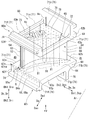
- the stationary blade 50 of the present embodiment has a blade body 51, an inner shroud 60i provided on one side of the blade body 51 in the blade height direction Dh, and a blade height of the blade body 51. It has an outer shroud 60o provided on the other side in the direction Dh.
- the blade height direction Dh becomes the radial direction Dr.
- the height direction first side Dh1 which is one side of the blade height direction Dh becomes the radial outer side Dr
- the height direction second side Dh2 which is the other side of the blade height direction Dh becomes the radial inner side.
- the inner shroud 60i is provided on the radial inner Dri of the blade body 51
- the outer shroud 60o is provided on the radial outer Dro of the blade body 51.
- the blade height direction Dh will be referred to as the radial direction Dr
- the height direction first side Dh1 will be referred to as the radial outer Dro
- the height direction second side Dh2 will be referred to as the radial inner Dri.
- the wing body 51 has a front edge 52, a trailing edge 53, a negative pressure surface (back side surface) 54 which is a convex surface, and a positive pressure surface which is a concave surface. It has (ventral surface) 55 and.
- the front edge 52 and the trailing edge 53 exist at the connecting portion between the negative pressure surface 54 and the positive pressure surface 55.
- the front edge 52, the trailing edge 53, the negative pressure surface 54, and the positive pressure surface 55 all extend in the radial direction Dr, which is the blade height direction Dh.
- the front edge 52 is located on the Dau on the upstream side of the axis with respect to the trailing edge 53 in a state where the stationary blade 50 is attached to the turbine casing 45.
- the blade body 51 is arranged in the combustion gas flow path 49 through which the combustion gas G passes.
- the inner shroud 60i defines the edge of the radial inner Dri of the annular combustion gas flow path 49.
- the outer shroud 60o defines the edge of the radial outer Dro of the annular combustion gas flow path 49.
- the inner shroud 60i has a shroud main body 61, a peripheral wall 71, an upstream protrusion 74, and a retainer 76.
- the shroud main body 61 is a plate-shaped member that spreads in a direction including a directional component in a direction perpendicular to the radial direction Dr, which is the blade height direction Dh.
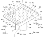
- the shroud main body 61 has a gas path surface 64, an anti-gas path surface 65, a front end surface 62f, a rear end surface 62b, a negative pressure side end surface 63n, and a positive pressure side end surface 63p.
- the gas path surface 64 is a surface that faces the outer Dro in the radial direction, which is the first side Dh1 in the height direction, and is in contact with the combustion gas G.
- the anti-gas path surface 65 is a surface facing the inner Dri in the radial direction, which is the second side Dh2 in the height direction.
- the anti-gas path surface 65 has a back-to-back relationship with the gas path surface 64.
- the front end surface 62f is located on the Dau on the upstream side of the axis line with respect to the blade body 51, and is a surface facing the Dau on the upstream side of the axis line.
- the rear end surface 62b is located on the Dad on the downstream side of the axis of the blade 51 and faces the Dad on the downstream side of the axis.
- the negative pressure side end surface 63n is a side end surface on the negative pressure side where the negative pressure surface 54 of the blade body 51 exists with reference to the camber line CL of the blade body 51, and is a surface located on the negative pressure side of the blade body 51.
- the negative pressure side end surface 63n connects the front end surface 62f and the rear end surface 62b.
- the positive pressure side end surface 63p is a side end surface on the positive pressure side where the positive pressure surface 55 of the blade body 51 exists with reference to the camber line CL of the blade body 51, and is a surface located on the positive pressure side of the blade body 51.
- the positive pressure side end surface 63p connects the front end surface 62f and the rear end surface 62b.
- the positive pressure side end surface 63p is located on the opposite side of the negative pressure side end surface 63n with reference to the blade body 51.
- the rear end surface 62b is substantially parallel to the front end surface 62f.
- the positive pressure side end surface 63p is substantially parallel to the negative pressure side end surface 63n. Therefore, the shroud main body 61 has a parallel quadrilateral shape as shown in FIG. 6 when viewed from the radial direction Dr.
- the direction in which the positive pressure side end surface 63p and the negative pressure side end surface 63n are aligned and orthogonal to the axis Ar is defined as the lateral direction Ds.
- the lateral Ds becomes the circumferential Dc.
- the lateral first side Ds1 which is one side of the lateral Ds becomes the circumferential positive pressure side Dcp
- the lateral second side Ds2 which is the other side of the lateral Ds becomes the circumferential negative pressure side Dcn. Therefore, in the following, the lateral direction Ds will be referred to as the circumferential direction Dc.
- the first side Ds1 in the lateral direction is defined as the positive pressure side Dcp in the circumferential direction
- the second Ds2 in the lateral direction is defined as the negative pressure side Dcn in the circumferential direction.
- the shroud body 61 further has a front end corner portion 66, a front end positive pressure side corner portion 67p, and a front end negative pressure side corner portion 67n.
- the front end surface 66 is a corner between the gas path surface 64 and the front end surface 62f.
- the front end angle portion 66 includes a front end inclined surface 66a that is inclined with respect to each of the front end surface 62f and the positive pressure side end surface 63p.
- the front end positive pressure side corner portion 67p is a corner portion of the gas path surface 64, the front end surface 62f, and the positive pressure side end surface 63p.
- the front end negative pressure side corner portion 67n is a corner portion of the gas path surface 64, the front end surface 62f, and the negative pressure side end surface 63n.
- the front end negative pressure side corner portion 67n includes a front end negative pressure side inclined surface 67na that is inclined with respect to each of the gas path surface 64, the front end surface 62f, and the negative pressure side end surface 63n.
- the front end inclined surface 66a is drawn as a curved surface that is inclined with respect to each of the front end surface 62f and the positive pressure side end surface 63p and connects the front end surface 62f and the positive pressure side end surface 63p. ..
- the front end inclined surface 66a may be a plane connecting the front end surface 62f and the positive pressure side end surface 63p as long as it is inclined with respect to each of the front end surface 62f and the positive pressure side end surface 63p.
- the peripheral wall 71 is a wall that projects from the shroud main body 61 to the inner Dri in the radial direction along the outer peripheral edge of the shroud main body 61.
- the peripheral wall 71 has a front peripheral wall 71f and a rear peripheral wall 71b facing each other in the axial direction Da, and a positive pressure side peripheral wall 71p and a negative pressure side peripheral wall 71n facing each other in the circumferential direction Dc.
- the front peripheral wall 71f is located on the Dau on the upstream side of the axis of the blade body 51.
- the front peripheral wall 71f projects from the shroud main body 61 to the radial outer Dro and the radial inner Dri from the positive pressure side peripheral wall 71p and the negative pressure side peripheral wall 71n.
- the surface of the front peripheral wall 71f facing the upstream side of the axis forms a part of the front end surface 62f of the inner shroud 60i.
- the rear peripheral wall 71b is located on the Dad on the downstream side of the axis of the blade body 51.
- the positive pressure side peripheral wall 71p is located on the positive pressure side Dcp in the circumferential direction with respect to the blade body 51.
- the surface of the positive pressure side peripheral wall 71p facing the positive pressure side Dcp in the circumferential direction forms a part of the positive pressure side end surface 63p of the inner shroud 60i.
- the negative pressure side peripheral wall 71n is located on the negative pressure side Dcn in the circumferential direction with respect to the blade body 51.
- the surface of the negative pressure side peripheral wall 71n facing the negative pressure side Dcn in the circumferential direction forms a part of the negative pressure side end surface 63n of the inner shroud 60i.
- a cavity 72 recessed toward the inner Dri in the radial direction is formed by the shroud main body 61 and the peripheral wall 71.
- the cavity 72 has an anti-gas path surface 65 of the shroud main body 61, a surface of the front peripheral wall 71f facing the axial downstream side Dad, a surface of the rear peripheral wall 71b facing the axial upstream side Dau, and a positive pressure side peripheral wall 71p in the circumferential negative pressure side. It is defined by a surface facing Dcn and a surface of the peripheral wall 71n on the negative pressure side facing the positive pressure side Dcp in the circumferential direction. Therefore, these surfaces form a cavity defining surface 73 that defines the cavity 72.
- the surface of the front peripheral wall 71f facing the downstream side of the axis Dad is referred to as the cavity front demarcating surface 73f.
- the retainer 76 is located between the front peripheral wall 71f and the rear peripheral wall 71b in the axial direction Da, and is formed from the negative pressure side end surface 63n to the positive pressure side end surface 63p.
- the retainer 76 is connected to the end 17a (see FIGS. 2 and 3) of the radial outer Dro of the inner cover 17 fixed to the gas turbine casing 15, and the portion of the radial inner Dri of the stationary blade 50 is inside. It plays a role of supporting the cover 17.
- the upstream side projecting portion 74 projects from a position away from the gas path surface 64 in the front end surface 62f to the axial upstream side Dau.
- the stationary blade 50 further includes a collision plate 78.
- the collision plate 78 divides the cavity 72 into a first-side cavity 72a, which is a region of the radial outer Dro, and a second-side cavity 72b, which is a region of the radial inner Dri.
- a plurality of through holes 79 penetrating in the radial direction Dr are formed in the collision plate 78.
- a part of the cooling air Ac existing in the radial inner Dri of the vane 50 flows into the second side cavity 72b.
- a part of the cooling air that has flowed into the second side cavity 72b flows into the first side cavity 72a through the through hole 79 of the collision plate 78, and impinge-cools the anti-gas path surface 65.
- the outer shroud 60o is basically the same as the configuration of the inner shroud 60i. Therefore, the outer shroud 60o also has the shroud main body 61, the peripheral wall 71, and the upstream side protrusion 74, similarly to the inner shroud 60i. However, the outer shroud 60o does not have a portion corresponding to the retainer 76 of the inner shroud 60i. Similar to the shroud main body 61 of the inner shroud 60i, the shroud main body 61 of the outer shroud 60o also has a gas path surface 64, an anti-gas path surface 65, a front end surface 62f, a rear end surface 62b, a negative pressure side end surface 63n, and a positive pressure side end surface.
- the peripheral wall 71 of the outer shroud 60o also has a front peripheral wall 71f, a rear peripheral wall 71b, a positive pressure side peripheral wall 71p, and a negative pressure side peripheral wall 71n, similarly to the peripheral wall 71 of the inner shroud 60i.
- the front peripheral wall 71f and the rear peripheral wall 71b of the outer shroud 60o serve to attach the stationary blade 50 to the inner peripheral side of the turbine casing 45 (see FIG. 2).
- the above-mentioned outlet seal 90 is formed in the outer outlet seal 90o connecting the radial outer Dro portion and the outer shroud 60o in the flange 37 of the tail cylinder 35 and in the flange 37 of the tail cylinder 35. It has an inner outlet seal 90i that connects the portion of the radial inner Dri and the inner shroud 60i.
- the inner outlet seal 90i includes a main plate 91, a downstream first plate 92a, a downstream second plate 92b, an upstream first plate 93a, and an upstream second plate 93b.
- the main plate 91 extends in the circumferential direction Dc and the radial direction Dr.
- the downstream first plate 92a and the downstream second plate 92b extend in the circumferential direction Dc and the axial direction Da.
- the downstream first plate 92a extends from the end of the radial outer Dro of the main plate 91 to the axis downstream Dad.
- the downstream second plate 92b extends from a position substantially intermediate between the end of the radial outer Dro and the end of the radial inner Dri of the main plate 91 to the cad on the downstream side of the axis.
- the downstream side second plate 92b faces the downstream side first plate 92a in the radial direction Dr at intervals in the radial direction Dr.
- the upstream first plate 93a extends in the circumferential direction Dc and the axial direction Da.
- the upstream side first plate 93a extends from the end of the radial inner Dri of the main plate 91 to the axis upstream side Dau.
- the upstream second plate 93b extends in the circumferential direction Dc and the radial direction Dr.
- the upstream second plate 93b extends from the end of the axial upstream Dau of the upstream first plate 93a to the outer Dro in the radial direction.
- the upstream second plate 93b faces the main plate 91 in the axial direction Da at intervals in the axial direction Da.
- the member closest to the combustion gas flow path 49 in the radial direction is the downstream first plate 92a.
- the downstream first plate 92a is located at the inner Dri in the radial direction with respect to the cylinder 36 of the tail cylinder 35 and the shroud main body 61 of the inner shroud 60i. Therefore, the downstream first plate 92a is separated from the combustion gas flow path 49 in the radial direction Dr.
- the inner outlet seal 90i has a tail cylinder connecting portion 94, a stationary blade connecting portion 95, and a cooling air passage 96.
- the tail cylinder connecting portion 94 is a groove recessed toward the inner Dri in the radial direction so that the flange 37 of the tail cylinder 35 can be inserted.
- the tail cylinder connecting portion 94 which is a groove, is formed by a main plate 91, an upstream first plate 93a, and an upstream second plate 93b.
- the stationary blade connecting portion 95 is a groove recessed toward the upstream Dau of the axis so that the upstream protruding portion 74 of the inner shroud 60i can enter.
- the stationary blade connecting portion 95 which is a groove, is formed by a main plate 91, a downstream first plate 92a, and a downstream second plate 92b.
- the cooling air passage 96 has an inlet 96i that opens at the end of the radial inner Dri of the main plate 91, and an outlet 96o that opens at the end of the axis downstream Dad of the downstream first plate 92a.
- the flange 37 of the tail tube 35 and the portion of the front end surface 62f of the inner shroud 60i that is separated from the gas path surface 64 are opposed to each other at intervals in the axial direction Da.
- the gap in the axial direction Da between the rear end surface 36b of the cylinder 36 and the front end surface 66 and the front end surface 62f of the inner shroud 60i forms the first gap S1.
- the space surrounded by the flange 37 of the tail tube 35, the front end surface 62f of the inner shroud 60i, and the downstream first plate 92a of the inner exit seal 90i forms a second gap S2. Therefore, the second gap S2 exists at a position separated from the combustion gas flow path 49 in the radial direction Dr.
- the first gap S1 and the second gap S2 are connected to each other in the radial direction Dr to form one gap space S.
- the outlet seal 90 also plays a role of preventing a part of the combustion gas G flowing in the tail cylinder 35 from flowing out into the intermediate casing 16 through the gap space S.
- the outer outlet seal 90o has the same configuration as the inner outlet seal 90i. However, the mutual relationship of the radial Dr in the component of the outer outlet seal 90o is opposite to the mutual relationship of the radial Dr in the component of the inner outlet seal 90i. Therefore, for example, the downstream first plate 92a of the outer outlet seal 90o is provided at the end of the radial inner Dri in the main plate 91 of the outer outlet seal 90o. Further, the tail cylinder connecting portion 94 of the outer outlet seal 90o is a groove recessed toward the outer Dro in the radial direction.
- a plurality of blade air passages 81 extending in the radial direction Dr are formed in the blade body 51, the outer shroud 60o, and the inner shroud 60i.
- Each wing air passage 81 is formed so as to be continuous from the outer shroud 60o to the inner shroud 60i via the wing body 51.
- the plurality of blade air passages 81 are lined up along the camber line CL of the blade body 51.
- a part of the adjacent wing air passage 81 communicates with each other at a portion of the radial outer Dro or a portion of the radial inner Dri.
- one of the plurality of wing air passages 81 is opened by the anti-gas path surface 65 of the outer shroud 60o.
- one of the plurality of wing air passages 81 is opened by the anti-gas path surface 65 of the inner shroud 60i.
- a part of the cooling air Ac existing in the radial outer Dro or the radial inner Dri of the vane 50 flows into the blade air passage 81 through the opening of the blade air passage 81.
- a plurality of blade surface ejection passages 82 penetrating from the blade air passage 81 to the combustion gas flow path 49 are formed in the front edge 52 and the trailing edge 53 of the blade body 51.
- a plurality of rear end passages 83, a plurality of first air passages 84, a plurality of second air passages 85, and a third air passage 86 are provided in the inner shroud 60i, as shown in FIGS. 5 and 6, a plurality of rear end passages 83, a plurality of first air passages 84, a plurality of second air passages 85, and a third air passage 86 are provided. It is formed.
- the plurality of rear end passages 83 are lined up in the circumferential direction Dc. These rear end passages 83 have an inlet 83i and an outlet 83o.
- the inlet 83i is a surface that defines the first-side cavity 72a, and is formed on a surface of the rear peripheral wall 71b that faces the upstream side of the axis Dau.
- the outlet 83o is formed on the rear end surface 62b.
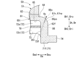
- the plurality of first air passages 84 are arranged in the circumferential direction Dc. As shown in FIG. 7, these first air passages 84 have a first inlet 84i and a first outlet 84o.
- the first inlet 84i is opened at a portion defining the second cavity 72b in the cavity front defining surface 73f.
- the first outlet 84o is opened at the front end inclined surface 66a in the front end corner portion 66.
- the first air passage 84 has a first outlet side portion 84po including the first outlet 84o in the first air passage 84.
- the first exit side portion 84po is formed so as to gradually move toward the outer Dro in the radial direction toward the upstream side Dau of the axis. Further, the first outlet side portion 84po is gradually inclined toward the circumferential positive pressure side Dcp toward the upstream side Dau of the axis line (see FIG. 6).
- the plurality of second air passages 85 are arranged in the circumferential direction Dc.
- the plurality of first air passages 84 and the plurality of second air passages 85 are alternately arranged in the circumferential direction Dc.
- these second air passages 85 have a second inlet 85i and a second outlet 85o.
- the second inlet 85i is opened at a portion defining the second cavity 72b in the cavity front defining surface 73f.
- the second outlet 85o is open at the front end surface 62f.
- the second outlet 85o faces the rear end surface 36b of the cylinder 36 in the axial direction Da.
- the second air passage 85 has a second outlet side portion 85po including the second outlet 85o in the second air passage 85.
- the second exit side portion 85po is formed so as to gradually move toward the outer Dro in the radial direction toward the upstream side Dau of the axis.
- the third air passage 86 has a third inlet 86i and a third outlet 86o.
- the third inlet 86i is opened at a portion defining the second cavity 72b in the cavity front defining surface 73f.
- the third outlet 86o is opened at the front end negative pressure side inclined surface 67na in the front end negative pressure side corner portion 67n.
- the third air passage 86 has a third outlet side portion 86po including the third outlet 86o in the third air passage 86.
- the third exit side portion 86po is formed so as to gradually move toward the outer Dro in the radial direction toward the upstream side Dau of the axis. Further, the third outlet side portion 86po is gradually inclined toward the circumferential negative pressure side Dcn toward the upstream side Dau of the axis line.
- a plurality of rear end passages 83 and a plurality of fourth air passages 87 are formed in the outer shroud 60o.
- the plurality of rear end passages 83 are arranged in the circumferential direction Dc like the plurality of rear end passages 83 of the inner shroud 60i. These rear end passages 83 have an inlet 83i and an outlet 83o.
- the inlet 83i is a surface defining the first side cavity 72a of the outer shroud 60o, and is formed on a surface of the rear peripheral wall 71b facing the upstream side Dau of the axis.
- the outlet 83o is formed on the rear end surface 62b of the outer shroud 60o.
- the plurality of fourth air passages 87 are lined up in the circumferential direction Dc. These fourth air passages 87 have a fourth inlet 87i and a fourth outlet 87o.
- the fourth entrance 87i is opened at a portion defining the first cavity 72a in the cavity front defining surface 73f of the outer shroud 60o.
- the fourth exit 87o is opened at the front end surface 62f of the outer shroud 60o.
- the outer shroud 60o may be formed with a first air passage 84 and a second air passage 85 instead of the above fourth air passage 87. Further, a third air passage 86 may be formed in the outer shroud 60o. In this way, when the first air passage 84, the second air passage 85, etc. are formed in the outer shroud 60o, the height direction first side Dh1 for the outer shroud 60o becomes the radial inner Dri, and the outer shroud The second side Dh2 in the height direction for 60o is the outer Dro in the radial direction. Therefore, for example, the first outlet side portion 84po in the first air passage 84 formed in the outer shroud 60o is formed so as to gradually move toward the inner Dri in the radial direction toward the upstream side Dau of the axis.
- the stationary blade 50 is exposed to the high temperature combustion gas G while the gas turbine 10 is being driven. Therefore, various passages are formed in the stationary blade 50, and air is passed through the passages to cool the stationary blade 50.
- a pressure distribution is generated in the circumferential direction Dc around the upstream side of the stationary blade 50 due to the relationship of the combustion gas flow flowing between the two stationary blades 50 adjacent to each other in the circumferential direction Dc. That is, around the upstream side of the stationary blade 50, the pressure of the portion on the first side Ds1 (positive pressure side) in the lateral direction becomes higher with reference to the front edge 52 of the blade body 51, and the pressure on the second side Ds2 in the lateral direction is relatively high. The pressure on the (negative pressure side) becomes low.
- the combustion gas flowing through the combustion gas flow path 49 is laterally oriented with respect to the front edge 52 of the blade body 51 between the rear end surface 36b of the tail cylinder 35 and the front end surface 62f of the inner shroud 60i.
- the combustion gas G is more likely to flow into the gap space S from the portion of the first side Ds1 (positive pressure side) in the lateral direction than the portion of the second side Ds2 (negative pressure side). Further, a part of the inflowing combustion gas G moves in the gap space S in the circumferential direction Dc and is discharged to the combustion gas flow path 49 on the second side Ds2 in the low pressure side.
- the gas path surface 64 of the inner shroud 60i is exposed to the combustion gas G. Further, when no air is flowing through the first air passage 84 and the second air passage 85, the combustion gas G flows into the gap space S between the tail tube 35 and the inner shroud 60i as described above. Therefore, the front end corner portion 66, which is a corner portion between the gas path surface 64 and the front end surface 62f, is heated on two sides by heat input from the gas path surface 64 side and the front end surface 62f side. Therefore, the front end corner portion 66 is more easily heated by the combustion gas G than the gas path surface 64 and the front end surface 62f.
- Compressed air in the intermediate casing 16 flows into the second side cavity 72b of the inner shroud 60i.
- a part of this compressed air flows into the first air passage 84 from the first inlet 84i as cooling air Ac.
- the other part of this compressed air flows into the second air passage 85 from the second inlet 85i as cooling air Ac.
- the other part of the compressed air flows into the third air passage 86 (see FIG. 8) from the third inlet 86i as the cooling air Ac.
- the cooling air Ac flowing into the first air passage 84 convection-cools the portion of the inner shroud 60i on the upstream side of the axis, especially the portion of the gas path surface 64 on the upstream side of the axis. To do.
- the cooling air Ac flows out into the combustion gas flow path 49 from the first outlet 84o formed at the front end corner portion 66.
- the cooling air Ac flowing out into the combustion gas flow path 49 functions as purge air, suppresses the combustion gas G from reaching the front end corner 66, and suppresses the heating of the front end corner 66 by the combustion gas G.
- the cooling air Ac flowing out into the combustion gas flow path 49 functions as purge air for suppressing the combustion gas G from flowing into the gap space S between the tail tube 35 and the inner shroud 60i, and also functions as the combustion gas G. By diluting the gas, the temperature of the gas flowing into the gap space S is lowered.
- the first outlet side portion 84po of the first air passage 84 gradually heads toward the outer Dro in the radial direction toward the upstream side Dau of the axis line. Therefore, the cooling air Ac flowing out from the first air passage 84 gradually goes toward the outer Dro in the radial direction as it goes toward the Dau on the upstream side of the axis. Therefore, the cooling air Ac flowing out from the first air passage 84 can effectively suppress the combustion gas G from reaching the front end corner portion 66, and can also suppress the combustion gas G from flowing into the gap space S. Further, the first outlet side portion 84po gradually approaches the circumferential positive pressure side Dcp toward the upstream side Dau of the axis line.
- the first air passage 84 is radially Dr.
- the passage length of the first air passage 84 can be lengthened by forming it as an inclined passage that also extends. Therefore, the cooling air Ac passing through the first air passage 84 can effectively convection-cool the portion of the inner shroud 60i on the upstream side of the axis.
- the cooling air Ac passing through the first air passage 84 has the effect of convection cooling the inner shroud 60i exposed to the combustion gas G. Further, the cooling air Ac flowing out from the first air passage 84 has an effect as purge air that suppresses the contact of the combustion gas G with the inner shroud 60i and suppresses the heating of the inner shroud 60i.
- the first air passage 84 has a greater effect of convection cooling by the cooling air Ac passing through the first air passage 84 than the effect of allowing the cooling air Ac flowing out of the first air passage 84 to function as purge air. It is a passage.
- the cooling air Ac that has flowed into the second air passage 85 convection-cools the portion of the inner shroud 60i on the upstream side of the axis, particularly around the front end surface 62f, in the process of passing through the second air passage 85.
- the cooling air Ac flows out into the gap space S from the second outlet 85o formed on the front end surface 62f.
- the cooling air Ac flowing out into the gap space S suppresses the combustion gas G from reaching the front end surface 62f facing the gap space S, so that the front end surface 62f and the rear end surface 36b of the tail tube 35 due to the combustion gas G Suppress the heating of.
- the cooling air Ac cools the area around the front end surface 62f by convection and dilutes the combustion gas G flowing into the gap space S to lower the gas temperature in the gap space S, thereby lowering the front end surface 62f and the tail tube 35. It suppresses heating of the rear end surface 36b and its surroundings. Further, the cooling air Ac flowing out into the gap space S functions as purge air that suppresses the combustion gas G from flowing into the gap space S.
- the second outlet side portion 85po of the second air passage 85 gradually heads toward the outer Dro in the radial direction toward the upstream side Dau of the axis line. Therefore, the cooling air Ac flowing out from the second air passage 85 gradually goes toward the outer Dro in the radial direction as it goes toward the Dau on the upstream side of the axis. Therefore, the cooling air Ac flowing out from the second air passage 85 can effectively suppress the combustion gas G from flowing into the gap space S.
- the second air passage 85 is a passage in which the effect of making the cooling air Ac function as purge air is greater than the effect of convection cooling as compared with the first air passage 84.
- the cooling air Ac flowing into the third air passage 86 is a portion of the inner shroud 60i on the upstream side of the axis, particularly the Dau on the upstream side of the axis of the gas path surface 64 and in the circumferential direction.
- the portion of the negative pressure side Dcn and the portion of the negative pressure side end surface 63n on the upstream side of the axis line Dau are convected-cooled.
- the cooling air Ac flows out into the combustion gas flow path 49 from the third outlet 86o formed at the front end negative pressure side corner portion 67n.
- the cooling air Ac flowing out into the combustion gas flow path 49 suppresses the combustion gas G from reaching the front end negative pressure side corner 67n, thereby suppressing the heating of the front end negative pressure side corner 67n by the combustion gas G. That is, the cooling air Ac cools the front end negative pressure side corner portion 67n and its surroundings with a film. Further, the cooling air Ac flowing out into the combustion gas flow path 49 suppresses the combustion gas G from flowing into the gap space S between the tail tube 35 and the inner shroud 60i, and the gas flowing into the gap space S. Lower the temperature of.
- the first air passage 84 and the second air passage 85 only one of the air passages can cool the portion of the inner shroud 60i on the upstream side of the axis, and can suppress thermal damage in this portion.
- a case where the portion of the inner shroud 60i on the upstream side of the axis Dau is cooled only by the first air passage 84 will be considered.
- the effect of the second air passage 85 also needs to be borne by the first air passage 84. Therefore, for example, by increasing the passage cross-sectional area of the first air passage 84, the flow rate of the cooling air Ac flowing through the first air passage 84 flows through the first air passage 84 and the second air passage 85 in the present embodiment. It needs to be larger than the total flow rate of the cooling air Ac.
- the portion of the inner shroud 60i on the upstream side of the axis Dau is cooled only by the second air passage 85.
- the effect of the first air passage 84 also needs to be borne by the first air passage 84. Therefore, for example, by increasing the number of the second air passages 85, the flow rate of the cooling air Ac flowing through the second air passage 85 is adjusted to the cooling air flowing through the first air passage 84 and the second air passage 85 in the present embodiment. It needs to be larger than the total flow rate of Ac.
- the inner shroud 60i of the present embodiment has the first air passage 84 and the second air passage 85, the inner shroud 60i is effectively cooled to improve the durability of the inner shroud 60i.
- the amount of cooling air Ac used to cool the inner shroud 60i can be suppressed.
- the number of the first air passages 84 and the number of the second air passages 85 do not have to be the same.
- the number of the first air passages 84 may be larger than the number of the second air passages 85.
- the number of the second air passages 85 may be larger than the number of the first air passages 84. Therefore, it is not necessary to arrange the plurality of first air passages 84 and the plurality of second air passages 85 alternately in the circumferential direction Dc.
- the total passage cross-sectional area of the first air passage 84 and the total passage cross-sectional area of the second air passage 85 do not have to be the same.
- the passage cross-sectional area of the first air passage 84 may be larger than the passage cross-sectional area of the second air passage 85.
- first outlet 84o of the first air passage 84 it is not necessary to arrange the first outlet 84o of the first air passage 84 in the entire front end corner portion 66 of the inner shroud 60i except for the end of the circumferential positive pressure side Dcp and the end of the circumferential negative pressure side Dcn. Further, it is not necessary to arrange the second outlet 85o of the second air passage 85 in the entire front end surface 62f of the inner shroud 60i except for the end of the circumferential positive pressure side Dcp and the end of the circumferential negative pressure side Dcn.
- the combustion gas G is located between the rear end surface 36b of the tail tube 35 and the front end surface 62f of the inner shroud 60i from the portion of the circumferential negative pressure side Dcn with reference to the front edge 52 of the blade body 51.
- the combustion gas G easily flows into the gap space S from the portion of the Dcp on the positive pressure side in the circumferential direction. Therefore, for example, the first outlet 84o of the first air passage 84 may be arranged only on the positive pressure side Dcp in the circumferential direction with reference to the front edge 52 of the blade body 51 in the front end corner portion 66.
- the second outlet 85o of the second air passage 85 may be arranged only on the circumferential positive pressure side Dcp with reference to the front edge 52 of the blade body 51.
- the first outlet 84o of the first air passage 84 is arranged only on the circumferential positive pressure side Dcp with reference to the front edge 52 of the blade body 51, and the front end surface 62f.
- the second outlet 85o of the second air passage 85 does not have to be arranged in the entire area except the end of the circumferential positive pressure side Dcp and the end of the circumferential negative pressure side Dcn.
- the first outlet 84o of the first air passage 84 is arranged in the entire front end corner portion 66 except for the end of the circumferential positive pressure side Dcp and the end of the circumferential negative pressure side Dcn, and the wing of the front end surface 62f
- the second outlet 85o of the second air passage 85 may be arranged only on the circumferential positive pressure side Dcp with reference to the front edge 52 of the body 51.
- the outer shroud 60o may be formed with a first air passage 84 and a second air passage 85 instead of the fourth air passage 87. Further, a third air passage 86 may be formed in the outer shroud 60o.
- the stationary blade can be effectively cooled, and the amount of cooling air used can be suppressed while improving the durability.
Abstract
A stator blade (50) comprises a blade body (51) and a shroud (60i). The shroud has a gas path surface (64), a leading-end surface (62f), a leading-end corner (66) that is the corner of the gas path surface and the leading-end surface, a cavity-demarcating surface (73) that demarcates a cavity (72) into which cooling air flows, a first air passage (84) through which cooling air (Ac) flows, and a second air passage (85) through which cooling air flows. The first air passage (84) has a first inlet (84i) opening in the cavity-demarcating surface (73), and a first outlet (84o) opening in the leading-end corner (66). The second air passage (85) has a second inlet (85i) opening in the cavity-demarcating surface (73), and a second outlet (85o) opening in the leading-end surface (62f).
Description
本発明は、静翼、及びこれを備えているガスタービンに関する。
本願は、2019年8月16日に、日本国に出願された特願2019-149245号に基づき優先権を主張し、この内容をここに援用する。 The present invention relates to a stationary blade and a gas turbine including the blade.
The present application claims priority based on Japanese Patent Application No. 2019-149245 filed in Japan on August 16, 2019, the contents of which are incorporated herein by reference.
ガスタービンは、空気を圧縮して圧縮空気を生成する圧縮機と、圧縮空気中で燃料を燃焼させて燃料ガスを生成する燃焼器と、燃焼ガスで駆動するタービンと、を備える。タービンは、軸線を中心として回転するタービンロータと、このロータを覆うタービンケーシングと、複数の静翼列と、を備える。タービンロータは、軸線を中心とするロータ軸と、ロータ軸に取り付けられている複数の動翼列と、を有する。複数の動翼列は、軸線が延びる軸線方向に並んでいる。各動翼列は、いずれも、軸線に対する周方向に並ぶ複数の動翼を有する。複数の静翼列は、軸線方向に並んで、タービンケーシングの内周側に取り付けられている。複数の静翼列のそれぞれは、複数の動翼列のうちのいずれか一の動翼列の軸線上流側に配置されている。各静翼列は、いずれも、軸線に対する周方向に並ぶ複数の静翼を有する。
The gas turbine includes a compressor that compresses air to generate compressed air, a combustor that burns fuel in compressed air to generate fuel gas, and a turbine driven by combustion gas. The turbine includes a turbine rotor that rotates about an axis, a turbine casing that covers the rotor, and a plurality of vane trains. The turbine rotor has a rotor shaft centered on an axis and a plurality of blade rows attached to the rotor shaft. The plurality of blade rows are arranged in the axial direction in which the axis extends. Each blade row has a plurality of blades arranged in the circumferential direction with respect to the axis. A plurality of vane rows are arranged in the axial direction and attached to the inner peripheral side of the turbine casing. Each of the plurality of blade rows is arranged on the upstream side of the axis of any one of the plurality of blade rows. Each vane row has a plurality of vanes aligned in the circumferential direction with respect to the axis.
静翼は、軸線に対する径方向に延びて翼形を成す翼体と、翼体の径方向内側に設けられている内側シュラウドと、翼体の径方向外側に設けられている外側シュラウドと、を有する。静翼の翼体は、燃焼ガスが通る燃焼ガス流路内に配置される。内側シュラウドは、燃焼ガス流路の径方向内側の縁を画定する。外側シュラウドは、燃焼ガス流路の径方向外側の縁を画定する。
A stationary blade includes a blade body that extends radially with respect to the axis to form an airfoil, an inner shroud provided on the radial inner side of the blade body, and an outer shroud provided on the radial outer side of the blade body. Have. The blade body of the stationary blade is arranged in the combustion gas flow path through which the combustion gas passes. The inner shroud defines the radial inner edge of the combustion gas flow path. The outer shroud defines the radial outer edge of the combustion gas flow path.
ガスタービンの静翼は、高温の燃焼ガスに晒される。このため、静翼は、一般的に、空気等で冷却される。
The stationary blades of gas turbines are exposed to high temperature combustion gas. Therefore, the stationary blade is generally cooled by air or the like.
例えば、以下の特許文献1に記載の静翼の内側シュラウドには、冷却空気が通る冷却空通路が形成されている。内側シュラウドは、径方向外側を向くガスパス面と、径方向内側を向く反ガスパス面と、軸線上流側を向く前端面と、を有する。ガスパス面は、燃焼ガスに晒される。前端面は、燃焼ガスに接する可能性がある。一方、反ガスパス面は、圧縮空気からの圧縮空気に接する。冷却空気通路は、反ガスパス面で開口している入口と、前端面で開口している出口と、を有する。冷却空気通路には、圧縮空気が冷却空気として入口から流入する。この冷却空気は、この冷却空気通路を通る過程で、ガスパス面を冷却する。この冷却空気は、前端面に形成されている出口から流出する。
For example, the inner shroud of the stationary blade described in Patent Document 1 below is formed with a cooling air passage through which cooling air passes. The inner shroud has a gas path surface facing outward in the radial direction, an anti-gas path surface facing inward in the radial direction, and a front end surface facing upstream of the axis. The gas path surface is exposed to combustion gas. The front end face may come into contact with combustion gas. On the other hand, the anti-gas path surface is in contact with the compressed air from the compressed air. The cooling air passage has an inlet that is open on the anti-gas path surface and an outlet that is open on the front end surface. Compressed air flows into the cooling air passage as cooling air from the inlet. This cooling air cools the gas path surface in the process of passing through the cooling air passage. This cooling air flows out from the outlet formed on the front end face.
ガスタービンの静翼に関しては、この静翼を効果的に冷却して、静翼の耐久性を向上させつつも、この静翼を冷却するための空気の使用量をできるかぎり減らすことが望まれている。
With respect to the vane of a gas turbine, it is desirable to effectively cool the vane to improve the durability of the vane while reducing the amount of air used to cool the vane as much as possible. ing.
そこで、本発明は、効率的に冷却可能な静翼、及びこの静翼を備えているガスタービンを提供することを目的とする。
Therefore, an object of the present invention is to provide a stationary blade capable of efficiently cooling and a gas turbine provided with the stationary blade.
前記目的を達成するための発明に係る一態様の静翼は、
翼形を成す翼体と、前記翼体における翼高さ方向の一方側である高さ方向第一側と前記翼高さ方向の他方側のである高さ方向第二側とのうち、前記高さ方向第二側の端に設けられているシュラウドと、を備える。前記シュラウドは、前記高さ方向第一側を向いて、燃焼ガスに接するガスパス面と、前記翼体の前縁に対する後縁が存在する側であって、前記燃焼ガスが流れてゆく下流側を向き、前記翼体よりも前記下流側に位置する後端面と、前記下流側とは反対側の上流側を向き、前記翼体よりも前記上流側に位置する前端面と、前記前端面と前記後端面とをつなぎ、前記翼体のキャンバーラインを基準にして前記翼体の正圧面が存在する正圧側の側端面であって、前記翼体よりも前記正圧側に位置する正圧側端面と、前記前端面と前記後端面とをつなぎ、前記翼体のキャンバーラインを基準にして前記翼体の負圧面が存在する負圧側の側端面であって、前記翼体よりも前記負圧側に位置する負圧側端面と、前記ガスパス面と前記前端面との角部である前端角部と、前記前端面と前記後端面と前記正圧側端面と前記負圧側端面とで囲まれた領域内に形成され、冷却空気が流入するキャビティを画定するキャビティ画定面と、前記冷却空気が流れる第一空気通路と、前記冷却空気が流れる第二空気通路と、を有する。前記第一空気通路は、前記キャビティ画定面で開口している第一入口と、前記前端角部で開口している第一出口と、を有する。前記第二空気通路は、前記キャビティ画定面で開口している第二入口と、前記前端面で開口している第二出口と、を有する。 One aspect of the stationary wing according to the invention for achieving the above object is
The height of the wing body forming the wing shape, the first side in the height direction which is one side in the wing height direction of the wing body, and the second side in the height direction which is the other side in the wing height direction. It is provided with a shroud provided at the second end in the longitudinal direction. The shroud faces the first side in the height direction, and is the side where the gas path surface in contact with the combustion gas and the trailing edge with respect to the front edge of the wing body exist, and the downstream side through which the combustion gas flows. The rear end surface located on the downstream side of the wing body, the front end surface located on the upstream side of the wing body facing the upstream side opposite to the downstream side, the front end surface and the said A positive pressure side end surface that connects the rear end surface and has a positive pressure surface of the blade with reference to the camber line of the blade, and is located on the positive pressure side of the blade. It is a side end surface on the negative pressure side where the negative pressure surface of the blade body exists by connecting the front end surface and the rear end surface with reference to the camber line of the blade body, and is located on the negative pressure side of the blade body. It is formed in a region surrounded by a negative pressure side end surface, a front end corner portion which is a corner portion between the gas path surface and the front end surface, the front end surface, the rear end surface, the positive pressure side end surface, and the negative pressure side end surface. It has a cavity defining surface that defines a cavity into which cooling air flows, a first air passage through which the cooling air flows, and a second air passage through which the cooling air flows. The first air passage has a first inlet that is open at the cavity defining surface and a first outlet that is open at the front end corner. The second air passage has a second inlet that is open at the cavity defining surface and a second outlet that is open at the front end surface.
キャビティ内に流入した冷却空気の一部は、第一入口から第一空気通路内に流入する。
キャビティ内に流入した冷却空気の他の一部は、第二入口から第二空気通路内に流入する。第一空気通路に流入した冷却空気は、この第一空気通路を通過する過程で、シュラウドの上流側の部分、特にガスパス面の上流側の部分を対流冷却する。冷却空気は、前端角部に形成されている第一出口から燃焼ガス流路内に流出する。燃焼ガス流路内に流出した冷却空気は、燃焼ガスが前端角部に至るのを抑制することで、燃焼ガスによる前端角部の加熱を抑制する。さらに、燃焼ガス流路内に流出した冷却空気は、尾筒とシュラウドとの間の隙間空間に燃焼ガスが流れ込むのを抑制すると共に、この隙間空間に流入するガスの温度を下げる。 A part of the cooling air that has flowed into the cavity flows into the first air passage from the first inlet.
The other part of the cooling air that has flowed into the cavity flows into the second air passage from the second inlet. The cooling air flowing into the first air passage convection-cools the upstream part of the shroud, particularly the upstream part of the gas path surface in the process of passing through the first air passage. The cooling air flows out into the combustion gas flow path from the first outlet formed at the front end corner. The cooling air flowing out into the combustion gas flow path suppresses the combustion gas from reaching the front end corner, thereby suppressing the heating of the front end corner by the combustion gas. Further, the cooling air flowing out into the combustion gas flow path suppresses the combustion gas from flowing into the gap space between the tail tube and the shroud, and lowers the temperature of the gas flowing into the gap space.
第二空気通路に流入した冷却空気は、この第二空気通路を通過する過程で、シュラウドの上流側の部分、特に前端面周りを対流冷却する。冷却空気は、前端面に形成されている第二出口から尾筒とシュラウドとの間の隙間空間に流出する。隙間空間に流出した冷却空気は、隙間空間にパージされるパージ空気の役割を果たし、燃焼ガスが尾筒とシュラウドの間の隙間空間を介して、尾筒の筒内周面より外周側の尾筒フランジとシュラウドとの間の隙間空間に燃焼ガスが流入するのを抑制している。その結果、燃焼ガスが隙間空間に面しているシュラウドの前端面、尾筒の後端面並びに尾筒フランジに至るのを抑制すると共に、燃焼ガスによるシュラウドの前端面、尾筒の後端面並びに尾筒フランジの加熱が抑制される。この冷却空気は、隙間空間に流入した燃焼ガスを希釈して、隙間空間のガス温度を下げ、シュラウドの前端面、尾筒の後端面、及びこれらの周囲の加熱を抑制する。つまり、隙間空間に流出した冷却空気は、この隙間空間に燃焼ガスが流れ込むのを抑制するパージ空気の役割を果たすと共に、燃焼ガスの希釈により、この隙間空間内の雰囲気ガスの温度を下げ、隙間空間を画定する面を有する部品の加熱を抑制する。
The cooling air that has flowed into the second air passage convectally cools the upstream part of the shroud, especially around the front end face, in the process of passing through this second air passage. The cooling air flows out from the second outlet formed on the front end surface into the gap space between the tail tube and the shroud. The cooling air that flows out into the gap space acts as purged air that is purged into the gap space, and the combustion gas passes through the gap space between the tail tube and the shroud, and the tail on the outer peripheral side of the inner peripheral surface of the tail tube. It suppresses the inflow of combustion gas into the gap space between the cylinder flange and the shroud. As a result, the combustion gas is suppressed from reaching the front end surface of the shroud facing the gap space, the rear end surface of the tail tube, and the tail tube flange, and the front end surface of the shroud, the rear end surface of the tail tube, and the tail due to the combustion gas. The heating of the cylinder flange is suppressed. This cooling air dilutes the combustion gas that has flowed into the gap space, lowers the gas temperature in the gap space, and suppresses heating of the front end surface of the shroud, the rear end surface of the tail tube, and their surroundings. That is, the cooling air that has flowed out into the gap space plays the role of purge air that suppresses the inflow of combustion gas into the gap space, and by diluting the combustion gas, the temperature of the atmospheric gas in this gap space is lowered, resulting in a gap. Suppresses heating of parts that have surfaces that define the space.
ところで、第一空気通路と第二空気通路とのうち、一方の空気通路のみでも、シュラウドの上流側の部分を冷却し、この部分の熱損傷を抑えることができる。ここで、仮に、第一空気通路のみでシュラウドの上流側の部分を冷却する場合について考察する。この場合、第二空気通路による効果も第一空気通路が担う必要がある。このため、例えば、第一空気通路の通路総断面積を大きくして、第一空気通路を流れる冷却空気の流量を、本態様において第一空気通路及び第二空気通路を流れる冷却空気の総流量より、多くする必要がある。
By the way, only one of the first air passage and the second air passage can cool the upstream part of the shroud and suppress the thermal damage of this part. Here, a case where the upstream part of the shroud is cooled only by the first air passage will be considered. In this case, the effect of the second air passage must also be borne by the first air passage. Therefore, for example, the total cross-sectional area of the passage of the first air passage is increased to increase the flow rate of the cooling air flowing through the first air passage, and the total flow rate of the cooling air flowing through the first air passage and the second air passage in this embodiment. Need more.
さらに、仮に、第二空気通路のみでシュラウドの上流側の部分を冷却する場合について考察する。この場合、第一空気通路による効果も第一空気通路が担う必要がある。このため、例えば、第二空気通路の通路総断面積を大きくして、第二空気通路を流れる冷却空気の流量を、本態様において第一空気通路及び第二空気通路を流れる冷却空気の総流量より、多くする必要がある。
Furthermore, consider the case where the upstream part of the shroud is cooled only by the second air passage. In this case, the effect of the first air passage must also be borne by the first air passage. Therefore, for example, by increasing the total cross-sectional area of the passage of the second air passage, the flow rate of the cooling air flowing through the second air passage is changed to the total flow rate of the cooling air flowing through the first air passage and the second air passage in this embodiment. Need more.
従って、本態様のシュラウドは、第一空気通路及び第二空気通路を有するので、シュラウドを効果的に冷却して、シュラウドの耐久性を向上させつつも、このシュラウドを冷却するための空気の使用量を抑えることができる。
Therefore, since the shroud of this embodiment has a first air passage and a second air passage, the use of air for cooling the shroud while effectively cooling the shroud and improving the durability of the shroud. The amount can be suppressed.
ここで、前記一態様の静翼において、前記シュラウドは、前記第一空気通路を複数有すると共に、前記第二空気通路を複数有してもよい。この場合、複数の前記第一空気通路及び複数の前記第二空気通路は、いずれも、前記正圧側端面と前記負圧側端面とが並ぶ側方向に並んでいる。
Here, in the stationary blade of the one aspect, the shroud may have a plurality of the first air passages and a plurality of the second air passages. In this case, the plurality of first air passages and the plurality of second air passages are all arranged in the side direction in which the positive pressure side end surface and the negative pressure side end surface are aligned.
複数の前記第一空気通路及び複数の前記第二空気通路を有する、前記態様の静翼において、複数の前記第一空気通路のうち、少なくとも一部の前記第一空気通路の前記第一出口は、前記前端角部のうち、前記翼体の前記前縁を基準にして、前記側方向の一方側である側方向第一側と前記側方向の他方側である側方向第二側とのうちの前記側方向第一側の領域に位置してもよい。さらに、複数の前記第二空気通路のうち、少なくとも一部の前記第二空気通路の前記第二出口は、前記前端面のうち、前記翼体の前記前縁を基準にして、前記側方向第一側の領域に位置してもよい。この場合、前記側方向第一側は、前記負圧側端面に対して前記正圧側端面が位置している側であり、前記側方向第二側は、前記側方向第一側とは反対側である。
In the stationary blade of the embodiment having the plurality of the first air passages and the plurality of the second air passages, at least a part of the first air passages is the first outlet of the first air passage. Of the front end corners, the first side in the side direction, which is one side in the side direction, and the second side in the side direction, which is the other side in the side direction, with reference to the front edge of the wing body. It may be located in the region on the first side in the lateral direction. Further, among the plurality of the second air passages, at least a part of the second outlets of the second air passages is the side direction first of the front end faces with reference to the front edge of the wing body. It may be located in the area on one side. In this case, the first side in the side direction is the side where the positive pressure side end face is located with respect to the negative pressure side end face, and the second side in the side direction is the side opposite to the first side in the side direction. is there.
燃焼ガス流路中で、静翼の上流側周りには、複数の静翼が並ぶ側方向に圧力分布が生じる。具体的に、静翼の上流側周りでは、翼体の前縁を基準にして側方向第一側(正圧側)の部分の圧力が高くなり、翼体の前縁を基準にして側方向第二側(負圧側)の部分の圧力が相対的に低くなる。このため、燃焼ガス流路を流れている燃焼ガスは、尾筒の後端面とシュラウドの前端面との間のうち、翼体の前縁を基準にして側方向第二側(負圧側)の部分よりも側方向第一側(正圧側)の部分から、燃焼ガスが隙間空間内に流入し易くなる。
このため、複数の第一空気通路のうち、少なくとも一部の第一空気通路の第一出口は、前端角部のうち、翼体の前縁を基準にして、側方向第一側(正圧側)の領域に位置していることが好ましい。また、複数の第二空気通路のうち、少なくとも一部の第二空気通路の第二出口は、前端面のうち、翼体の前縁を基準にして、側方向第一側(正圧側)の領域に位置していることが好ましい。 In the combustion gas flow path, a pressure distribution is generated around the upstream side of the vanes in the direction in which a plurality of vanes are lined up. Specifically, around the upstream side of the stationary blade, the pressure on the first side (positive pressure side) in the lateral direction with reference to the front edge of the blade increases, and the pressure in the lateral direction with reference to the front edge of the blade increases. The pressure on the two sides (negative pressure side) becomes relatively low. Therefore, the combustion gas flowing in the combustion gas flow path is on the second side (negative pressure side) in the lateral direction with respect to the front edge of the blade body, which is between the rear end surface of the tail tube and the front end surface of the shroud. Combustion gas easily flows into the gap space from the portion on the first side (positive pressure side) in the lateral direction rather than the portion.
Therefore, of the plurality of first air passages, at least a part of the first outlets of the first air passages is the first side (positive pressure side) in the lateral direction with respect to the front edge of the blade body in the front end corner portion. ) Is preferably located in the area. Further, among the plurality of second air passages, at least a part of the second outlets of the second air passages is on the first side (positive pressure side) in the lateral direction with respect to the front edge of the blade body in the front end surface. It is preferably located in the area.
前記態様の静翼において、複数の前記第二空気通路のうち、前記少なくとも一部を除く前記第二空気通路の前記第二出口は、前記前端面のうち、前記翼体の前記前縁を基準にして、前記側方向第二側の領域に位置してもよい。
In the stationary blade of the above aspect, the second outlet of the second air passage except for at least a part of the plurality of second air passages is based on the front edge of the blade body in the front end surface. It may be located in the region on the second side in the lateral direction.
本態様では、第二空気通路の第二出口が、翼体の前縁を基準にして、側方向第二側の領域に配置される。従って、静翼の上流側周りにおける燃焼ガスの圧力変動等により、燃焼ガスの隙間空間への流入が、翼体の前縁を基準にて側方向第二側の領域において一時的に増加しようとしても、側方向の第二側の領域への燃焼ガスの流入増加を抑制できる。
In this embodiment, the second outlet of the second air passage is arranged in the region on the second side in the lateral direction with respect to the front edge of the wing body. Therefore, due to the pressure fluctuation of the combustion gas around the upstream side of the vane, the inflow of the combustion gas into the gap space tries to temporarily increase in the region on the second side in the lateral direction with respect to the front edge of the blade. However, it is possible to suppress an increase in the inflow of combustion gas into the region on the second side in the lateral direction.
複数の前記第一空気通路及び複数の前記第二空気通路を有する、以上のいずれかの前記態様の静翼において、複数の前記第一空気通路のうち、少なくとも一部の第一空気通路は、複数の前記第二空気通路のうちのいずれかの第二空気通路に対して、前記側方向で隣接していてもよい。
In the stationary blade of any of the above embodiments having the plurality of the first air passages and the plurality of the second air passages, at least a part of the first air passages among the plurality of first air passages is It may be adjacent to the second air passage of any one of the plurality of the second air passages in the lateral direction.
本態様では、一部の第一空気通路は、第二空気通路に対して側方向に隣接させ、第一空気通路と第二空気通路が側方向で交互に配置させている。従って、シュラウドの前縁角部と前端面の側方向における対流冷却が均一的に行われ、シュラウドの前縁角部及び前端面の熱応力が低減される。また、第二空気通路から排出されるパージ空気の偏流も抑制され、燃焼ガスの隙間空間への流入も一層抑制される。
In this embodiment, some of the first air passages are adjacent to the second air passage in the lateral direction, and the first air passage and the second air passage are alternately arranged in the lateral direction. Therefore, convection cooling is uniformly performed in the lateral direction of the front edge corner portion and the front end surface of the shroud, and the thermal stress of the front edge corner portion and the front end surface of the shroud is reduced. In addition, the drift of purged air discharged from the second air passage is suppressed, and the inflow of combustion gas into the gap space is further suppressed.
複数の前記第一空気通路及び複数の前記第二空気通路を有する、以上のいずれかの前記態様の静翼において、複数の前記第一空気通路と複数の前記第二空気通路とのうち、一方の通路の数は、他方の通路の数より多くてもよい。
In the stationary blade of any of the above embodiments having the plurality of the first air passages and the plurality of the second air passages, one of the plurality of the first air passages and the plurality of the second air passages. The number of passages in one may be greater than the number of passages in the other.
複数の前記第一空気通路及び複数の前記第二空気通路を有する、以上のいずれかの前記態様の静翼において、前記第一空気通路は、前記第一空気通路中の前記第一出口を含む第一出口側部を有し、前記第一空気通路のうちで少なくとも前記第一出口側部は、前記上流側に向かうに連れて、次第に前記高さ方向第一側に向かうよう傾斜していてもよい。
In the stationary blade of any of the above embodiments having the plurality of the first air passages and the plurality of the second air passages, the first air passage includes the first outlet in the first air passage. It has a first outlet side portion, and at least the first outlet side portion of the first air passage is gradually inclined toward the first side in the height direction toward the upstream side. May be good.
本態様では、第一空気通路から流出した冷却空気は、上流側に向かうに連れて、次第に高さ方向第一側に向かう。従って、この第一空気通路から流出した冷却空気により、効果的に、燃焼ガスが前端角部に至るのを抑制できると共に、尾筒とシュラウドとの間の隙間空間に燃焼ガスが流れ込むのを抑制できる。
In this embodiment, the cooling air flowing out from the first air passage gradually moves toward the first side in the height direction toward the upstream side. Therefore, the cooling air flowing out from the first air passage can effectively suppress the combustion gas from reaching the front end corner, and also suppress the combustion gas from flowing into the gap space between the tail tube and the shroud. it can.
前記第一出口側部を有する、前記態様の静翼において、前記第一空気通路の前記第一出口側部は、前記上流側に向かうに連れて、次第に、前記側方向の一方側である側方向第一側に向かうよう傾斜していてもよい。この場合、前記側方向第一側は、前記負圧側端面に対して前記正圧側端面が位置している側である。
In the stationary blade of the embodiment having the first outlet side portion, the first outlet side portion of the first air passage gradually becomes one side in the side direction toward the upstream side. It may be inclined toward the first side in the direction. In this case, the first side in the side direction is the side on which the positive pressure side end face is located with respect to the negative pressure side end face.
本態様では、第一入口が形成されているキャビティ前側画定面と第一出口が形成されている前端角部との間の距離が短くても、第一空気通路の通路長を長くすることができる。
従って、この第一空気通路を通過している冷却空気により、効果的に、内側シュラウドの上流側の部分を対流冷却できる。また、前述したように、燃焼ガス流路を流れている燃焼ガスは、尾筒の後端面とシュラウドの前端面との間のうち、翼体の前縁を基準にして側方向第一側(正圧側)の部分から、燃焼ガスが隙間空間内に流入し易い。本態様では、第一空気通路から流出した冷却空気は、上流側に向かいつつも、側方向第一側(正圧側)に向かうため、燃焼ガスが隙間空間内に流入するのを効果的に抑制することができる。 In this embodiment, the passage length of the first air passage can be increased even if the distance between the cavity front demarcation surface where the first inlet is formed and the front end corner where the first outlet is formed is short. it can.
Therefore, the cooling air passing through the first air passage can effectively convect cool the upstream portion of the inner shroud. Further, as described above, the combustion gas flowing in the combustion gas flow path is the first side in the lateral direction (with respect to the front edge of the blade body) between the rear end surface of the tail tube and the front end surface of the shroud. Combustion gas easily flows into the gap space from the positive pressure side). In this embodiment, the cooling air flowing out from the first air passage goes toward the first side (positive pressure side) in the lateral direction while heading toward the upstream side, so that the combustion gas is effectively suppressed from flowing into the gap space. can do.
以上のいずれかの前記態様の静翼において、前記前端角部は、前記ガスパス面及び前記前端面のそれぞれに対して傾斜している前端傾斜面を含んでもよい。この場合、前記第一出口は、前記前端傾斜面で開口している。
In any of the above aspects of the stationary blade, the front end corner portion may include a front end inclined surface that is inclined with respect to each of the gas path surface and the front end surface. In this case, the first outlet is opened at the front end inclined surface.
以上のいずれかの前記態様の静翼において、前記第二空気通路は、前記第二空気通路中で前記第二出口を含む第二出口側部を有し、前記第二空気通路のうちで少なくとも前記第二出口側部は、前記上流側に向かうに連れて、次第に、前記高さ方向第一側に向かうよう傾斜していてもよい。
In the stationary blade of any of the above aspects, the second air passage has a second outlet side portion including the second outlet in the second air passage, and at least among the second air passages. The second outlet side portion may be gradually inclined toward the first side in the height direction toward the upstream side.
以上のいずれかの前記態様の静翼において、前記キャビティを、前記高さ方向第一側の第一側キャビティと前記高さ方向第二側の第二側キャビティとに仕切る衝突板をさらに備えてもよい。この場合、前記衝突板には、前記翼高さ方向に貫通し、前記第二側キャビティ内の前記冷却空気を前記第一側キャビティ内に導く複数の貫通孔が形成されている。また、前記第一入口と前記第二入口とのうち、少なくとも、一方の入口は、前記キャビティ画定面のうちで前記第二側キャビティを画定する面で開口していてもよい。
In the stationary blade of any of the above aspects, a collision plate for partitioning the cavity into the first cavity on the first side in the height direction and the second cavity on the second side in the height direction is further provided. May be good. In this case, the collision plate is formed with a plurality of through holes that penetrate in the blade height direction and guide the cooling air in the second cavity into the first cavity. Further, at least one of the first inlet and the second inlet may be opened by the surface defining the second side cavity among the cavity defining surfaces.
冷却空気は、衝突板の貫通孔を介して、第二側キャビティから第一側キャビティ内に流入すると、圧力が低下すると共に、温度が上昇する。従って、空気通路の入口が、キャビティ画定面のうちで第二側キャビティを画定する面で開口していると、この空気通路に流入する冷却空気の圧力の低下を抑えることができると共に、この冷却空気の温度上昇を抑えることができる。
When the cooling air flows into the first cavity from the second cavity through the through hole of the collision plate, the pressure decreases and the temperature rises. Therefore, when the inlet of the air passage is opened at the surface defining the second side cavity among the cavity defining surfaces, it is possible to suppress a decrease in the pressure of the cooling air flowing into the air passage and to suppress the cooling. The temperature rise of the air can be suppressed.
前記衝突板を備える前記態様の静翼において、前記第一入口と前記第二入口とは、いずれも、前記キャビティ画定面のうちで前記第二側キャビティを画定する面で開口していてもよい。
In the stationary blade of the embodiment provided with the collision plate, both the first inlet and the second inlet may be opened at the surface defining the second side cavity among the cavity defining surfaces. ..
以上のいずれかの前記態様の静翼において、前記シュラウドは、前記ガスパス面と前記前端面と前記負圧側端面との角部である前端負圧側角部と、前記冷却空気が流れる第三空気通路と、を有してもよい。この場合、前記第三空気通路は、前記キャビティ画定面で開口している第三入口と、前記前端負圧側角部で開口している第三出口と、を有する。
In the stationary blade of any of the above aspects, the shroud has a front end negative pressure side corner portion which is a corner portion of the gas path surface, the front end surface, and the negative pressure side end surface, and a third air passage through which the cooling air flows. And may have. In this case, the third air passage has a third inlet that is open at the cavity defining surface and a third outlet that is open at the front end negative pressure side corner.
キャビティ内に流入した冷却空気の一部は、第三入口から第三空気通路内に流入する。
第三空気通路に流入した冷却空気は、この第三空気通路を通過する過程で、シュラウドの上流側の部分、特に、ガスパス面の上流側で且つ側方向第二側(負圧側)の部分、及び負圧側端面の上流側の部分を対流冷却する。冷却空気は、前端負圧側角部に形成されている第三出口から燃焼ガス流路内に流出する。燃焼ガス流路内に流出した冷却空気は、パージ空気として燃焼ガスが前端負圧側角部に至るのを抑制して、燃焼ガスによる前端負圧側角部の加熱を抑制する。 A part of the cooling air that has flowed into the cavity flows into the third air passage from the third inlet.
In the process of passing through the third air passage, the cooling air flowing into the third air passage is located on the upstream side of the shroud, particularly on the upstream side of the gas path surface and on the second side (negative pressure side) in the lateral direction. And the upstream part of the negative pressure side end face is convected cooled. The cooling air flows out into the combustion gas flow path from the third outlet formed at the front end negative pressure side corner. The cooling air flowing out into the combustion gas flow path suppresses the combustion gas reaching the front end negative pressure side corner as purge air, and suppresses the heating of the front end negative pressure side corner by the combustion gas.
前記第三空気通路を有する前記態様の静翼において、前記前端負圧側角部は、前記ガスパス面と前記前端面と前記負圧側端面とのそれぞれに対して傾斜している前端負圧側傾斜面を含み、前記第三出口は、前記前端負圧側傾斜面で開口していてもよい。
In the stationary blade of the embodiment having the third air passage, the front end negative pressure side corner portion has a front end negative pressure side inclined surface that is inclined with respect to each of the gas path surface, the front end surface, and the negative pressure side end surface. Including, the third outlet may be opened at the front end negative pressure side inclined surface.
前記目的を達成するための発明に係る一態様のガスタービンは、
以上のいずれかの態様の静翼を複数備えていると共に、軸線を中心として回転するタービンロータと、前記タービンロータを覆うタービンケーシングと、前記軸線が延びる軸線方向における軸線上流側から前記タービンケーシング内に前記燃焼ガスを送る燃焼器と、を備える。複数の前記静翼は、前記タービンケーシング内に配置されている。前記タービンロータは、前記軸線を中心とするロータ軸と、前記ロータ軸に取り付けられている複数の動翼と、を有する。複数の前記動翼は、前記軸線に対する周方向に並ぶ。複数の前記静翼は、前記周方向に並び、且つ複数の前記動翼よりも前記軸線上流側に位置し、前記翼高さ方向が前記軸線に対する径方向になり且つ前記上流側が前記軸線上流側になるよう、前記タービンケーシングに取り付けられている。 One aspect of the gas turbine according to the invention for achieving the above object is
A turbine rotor that rotates about an axis, a turbine casing that covers the turbine rotor, and the inside of the turbine casing from the upstream side of the axis in the axial direction in which the axis extends, while having a plurality of stationary blades of any of the above aspects. The turbine is provided with a combustor for sending the combustion gas. The plurality of vanes are arranged in the turbine casing. The turbine rotor has a rotor shaft centered on the shaft line and a plurality of moving blades attached to the rotor shaft. The plurality of blades are arranged in the circumferential direction with respect to the axis. The plurality of the stationary blades are arranged in the circumferential direction and are located on the upstream side of the axis with respect to the plurality of moving blades, the blade height direction is the radial direction with respect to the axis, and the upstream side is the upstream side of the axis. It is attached to the turbine casing so as to be.
ここで、前記態様のガスタービンにおいて、前記高さ方向第二側は、前記軸線に対する径方向内側であり、前記シュラウドは、前記翼体の前記径方向内側の端に設けられている内側シュラウドであってもよい。
Here, in the gas turbine of the above aspect, the second side in the height direction is the inner side in the radial direction with respect to the axis line, and the shroud is an inner shroud provided at the inner end in the radial direction of the blade body. There may be.
以上のいずれかの前記態様のガスタービンにおいて、前記燃焼器と前記静翼とを接続するシールを備えてもよい。前記燃焼器は、前記軸線方向における前記軸線上流側とは反対側の軸線下流側の方向成分を含む方向に燃料を噴射するバーナと、筒状を成し、前記バーナから噴射された燃料が燃焼する燃焼空間を形成する尾筒と、を有する。前記尾筒は、前記軸線下流側の方向成分を含む方向に延び、内周側に前記燃焼空間が形成されている筒と、前記筒の前記軸線下流側の下流端部から外周側に突出したフランジと、を有する。前記静翼の前記シュラウドは、前記前端面中の前記ガスパス面から離れた位置から前記上流側に突出した上流側突出部を有する。前記シールは、前記筒の外周面よりも外周側に位置する。前記筒の下流端と前記シュラウドの前記前端面とは、間隔をあけて対向する。前記シールは、前記尾筒の前記フランジに接続される尾筒接続部と、前記静翼の前記上流側突出部に接続される静翼接続部と、冷却空気が流れる冷却空気通路と、を有する。前記シールの前記冷却空気通路は、前記筒の前記下流端と前記シュラウドの前記前端面との間の空間と、前記尾筒の外周側の空間と、を連通させる。
The gas turbine of any of the above aspects may be provided with a seal connecting the combustor and the vane. The combustor has a tubular shape and a burner that injects fuel in a direction including a directional component on the downstream side of the axis opposite to the upstream side of the axis in the axial direction, and the fuel injected from the burner burns. It has a tail tube that forms a combustion space. The tail tube extends in a direction including a directional component on the downstream side of the axis, and projects from the tube in which the combustion space is formed on the inner peripheral side and the downstream end on the downstream side of the axis to the outer peripheral side. Has a flange. The shroud of the stationary blade has an upstream-side protruding portion that protrudes toward the upstream side from a position in the front end surface away from the gas path surface. The seal is located on the outer peripheral side of the outer peripheral surface of the cylinder. The downstream end of the cylinder and the front end surface of the shroud face each other with a gap. The seal has a tail cylinder connecting portion connected to the flange of the tail cylinder, a stationary blade connecting portion connected to the upstream protruding portion of the stationary blade, and a cooling air passage through which cooling air flows. .. The cooling air passage of the seal communicates a space between the downstream end of the cylinder and the front end surface of the shroud and a space on the outer peripheral side of the tail cylinder.
本発明の一態様によれば、静翼を効果的に冷却して、耐久性の向上を図りつつも冷却空気の使用量を抑えることができる。
According to one aspect of the present invention, the stationary blade can be effectively cooled, and the amount of cooling air used can be suppressed while improving the durability.
以下、本発明の各種実施形態及びその変形例について、図面を参照して詳細に説明する。
Hereinafter, various embodiments of the present invention and examples of modifications thereof will be described in detail with reference to the drawings.
「ガスタービンの実施形態」
ガスタービンの実施形態について、図1及び図2を参照して説明する。 "Implementation of Gas Turbine"
Embodiments of the gas turbine will be described with reference to FIGS. 1 and 2.
ガスタービンの実施形態について、図1及び図2を参照して説明する。 "Implementation of Gas Turbine"
Embodiments of the gas turbine will be described with reference to FIGS. 1 and 2.
図1に示すように、本実施形態のガスタービン10は、空気Aを圧縮する圧縮機20と、圧縮機20で圧縮された空気A中で燃料Fを燃焼させて燃焼ガスGを生成する燃焼器30と、燃焼ガスGにより駆動するタービン40と、を備えている。
As shown in FIG. 1, the gas turbine 10 of the present embodiment has a compressor 20 that compresses air A and combustion that burns fuel F in the air A compressed by the compressor 20 to generate combustion gas G. It includes a vessel 30 and a turbine 40 driven by a combustion gas G.
圧縮機20は、軸線Arを中心として回転する圧縮機ロータ21と、圧縮機ロータ21を覆う圧縮機ケーシング25と、複数の静翼列26と、を有する。タービン40は、軸線Arを中心として回転するタービンロータ41と、タービンロータ41を覆うタービンケーシング45と、複数の静翼列46と、を有する。なお、以下では、軸線Arが延びる方向を軸線方向Da、この軸線Arを中心とした周方向を単に周方向Dcとし、軸線Arに対して垂直な方向を径方向Drとする。また、軸線方向Daの一方側を軸線上流側Dau、その反対側を軸線下流側Dadとする。また、径方向Drで軸線Arに近づく側を径方向内側Dri、その反対側を径方向外側Droとする。
The compressor 20 has a compressor rotor 21 that rotates about the axis Ar, a compressor casing 25 that covers the compressor rotor 21, and a plurality of stationary blade rows 26. The turbine 40 has a turbine rotor 41 that rotates about the axis Ar, a turbine casing 45 that covers the turbine rotor 41, and a plurality of stationary blade rows 46. In the following, the direction in which the axis Ar extends is referred to as the axial direction Da, the circumferential direction centered on the axis Ar is simply referred to as the circumferential direction Dc, and the direction perpendicular to the axis Ar is referred to as the radial direction Dr. Further, one side of the axial direction Da is referred to as an axial upstream side Dau, and the opposite side is referred to as an axial downstream side Dad. Further, the side approaching the axis Ar in the radial direction is the radial inner Dri, and the opposite side is the radial outer Dro.
圧縮機20は、タービン40に対して軸線上流側Dauに配置されている。
The compressor 20 is arranged on the Dau on the upstream side of the axis with respect to the turbine 40.
圧縮機ロータ21とタービンロータ41とは、同一軸線Ar上に位置し、互いに接続されてガスタービンロータ11を成す。このガスタービンロータ11には、例えば、発電機GENのロータが接続されている。ガスタービン10は、さらに、中間ケーシング16を備える。この中間ケーシングは、軸線方向Daで、圧縮機ケーシング25とタービンケーシング45との間に配置されている。圧縮機ケーシング25と中間ケーシング16とタービンケーシング45とは、互いに接続されてガスタービンケーシング15を成す。
The compressor rotor 21 and the turbine rotor 41 are located on the same axis Ar and are connected to each other to form the gas turbine rotor 11. For example, the rotor of the generator GEN is connected to the gas turbine rotor 11. The gas turbine 10 further includes an intermediate casing 16. This intermediate casing is arranged between the compressor casing 25 and the turbine casing 45 in the axial direction Da. The compressor casing 25, the intermediate casing 16 and the turbine casing 45 are connected to each other to form the gas turbine casing 15.
圧縮機ロータ21は、軸線Arを中心として軸線方向Daに延びるロータ軸22と、このロータ軸22に取り付けられている複数の動翼列23と、を有する。複数の動翼列23は、軸線方向Daに並んでいる。各動翼列23は、いずれも、周方向Dcに並んでいる複数の動翼23aで構成されている。複数の動翼列23の各軸線下流側Dadには、複数の静翼列26のうちのいずれか一の静翼列26が配置されている。各静翼列26は、圧縮機ケーシング25の内側に設けられている。各静翼列26は、いずれも、周方向Dcに並んでいる複数の静翼26aで構成されている。
The compressor rotor 21 has a rotor shaft 22 extending in the axial direction Da about the axis Ar, and a plurality of rotor blade rows 23 attached to the rotor shaft 22. The plurality of blade rows 23 are arranged in the axial direction Da. Each of the moving blade rows 23 is composed of a plurality of moving blades 23a arranged in the circumferential direction Dc. A stationary blade row 26 of any one of the plurality of stationary blade rows 26 is arranged on the Dad on the downstream side of each axis of the plurality of moving blade rows 23. Each vane row 26 is provided inside the compressor casing 25. Each of the stationary blade rows 26 is composed of a plurality of stationary blades 26a arranged in the circumferential direction Dc.
タービンロータ41は、図1及び図2に示すように、軸線Arを中心として軸線方向Daに延びるロータ軸42と、このロータ軸42に取り付けられている複数の動翼列43と、を有する。複数の動翼列43は、軸線方向Daに並んでいる。各動翼列43は、いずれも、周方向Dcに並んでいる複数の動翼43aで構成されている。複数の動翼列43の各軸線上流側Dauには、複数の静翼列46のうちのいずれか一の静翼列46が配置されている。各静翼列46は、タービンケーシング45の内側に設けられている。各静翼列46は、いずれも、周方向Dcに並んでいる複数の静翼46aで構成されている。
As shown in FIGS. 1 and 2, the turbine rotor 41 has a rotor shaft 42 extending in the axial direction Da about the axis Ar, and a plurality of blade rows 43 attached to the rotor shaft 42. The plurality of blade rows 43 are arranged in the axial direction Da. Each of the moving blade rows 43 is composed of a plurality of moving blades 43a arranged in the circumferential direction Dc. A stationary blade row 46 of any one of the plurality of stationary blade rows 46 is arranged on each axis upstream Dau of the plurality of moving blade rows 43. Each vane row 46 is provided inside the turbine casing 45. Each of the stationary blade rows 46 is composed of a plurality of stationary blades 46a arranged in the circumferential direction Dc.
タービンケーシング45は、その外殻を構成する筒状の外側ケーシング45aと、外側ケーシング45aの内側に固定されている内側ケーシング45bと、内側ケーシング45bの内側に固定されている複数の分割環45cとを有する。複数の分割環45cは、いずれも、複数の静翼列46の相互の間の位置に設けられている。従って、各分割環45cの径方向内側Driには、動翼列43が配置されている。
The turbine casing 45 includes a tubular outer casing 45a constituting the outer shell, an inner casing 45b fixed to the inside of the outer casing 45a, and a plurality of dividing rings 45c fixed to the inside of the inner casing 45b. Has. The plurality of dividing rings 45c are all provided at positions between the plurality of stationary blade rows 46. Therefore, the rotor blade row 43 is arranged on the radial inner Dri of each dividing ring 45c.
ロータ軸42の外周側とタービンケーシング45の内周側との間であって、軸線方向Daで静翼46a及び動翼43aが配置されている環状の空間は、燃焼器30からの燃焼ガスGが流れる燃焼ガス流路49を成す。この燃焼ガス流路49は、軸線Arを中心として環状を成し、軸線方向Daに長い。タービンケーシング45の内側ケーシング45bには、径方向外側Droから径方向内側Driに貫通する冷却空気通路45pが形成されている。この冷却空気通路45pを通った冷却空気は、静翼46a内及び分割環45c内に導入されて、静翼46a及び分割環45cの冷却に利用される。なお、静翼列46によっては、ガスタービンケーシング15内の空気が、冷却空気として、タービンケーシング45の冷却空気通路45pを経ずにこの静翼列46を構成する静翼46aに供給される場合もある。
The annular space between the outer peripheral side of the rotor shaft 42 and the inner peripheral side of the turbine casing 45 where the stationary blades 46a and the moving blades 43a are arranged in the axial direction Da is the combustion gas G from the combustor 30. Form a combustion gas flow path 49 through which The combustion gas flow path 49 forms an annular shape about the axis Ar and is long in the axial direction Da. The inner casing 45b of the turbine casing 45 is formed with a cooling air passage 45p penetrating from the radial outer Dro to the radial inner Dri. The cooling air that has passed through the cooling air passage 45p is introduced into the stationary blade 46a and the split ring 45c and used for cooling the stationary blade 46a and the split ring 45c. Depending on the stationary blade row 46, the air in the gas turbine casing 15 is supplied as cooling air to the stationary blades 46a constituting the stationary blade row 46 without passing through the cooling air passage 45p of the turbine casing 45. There is also.
燃焼器30は、中間ケーシング16に取り付けられている。この燃焼器30は、図2に示すように、燃料が燃焼する内筒(又は燃焼筒)33と、この内筒33内に燃料を噴射する複数のバーナ31と、複数のバーナ31を支えるバーナ枠32と、内筒33の下流側に接続されている尾筒35と、を有する。尾筒35は、燃焼器軸線Ca周りに筒状の筒36と、この筒36の一端部から外周側に突出したフランジ37と、を有する。この筒36の他端部には、バーナ枠32が装着されている。この筒36の内周側が燃焼空間を形成する。この筒36は、燃焼器30が中間ケーシング16に取り付けられている状態では、軸線下流側Dadに延びている。フランジ37は、この筒36の軸線下流側Dadの下流側端部に設けられている。
The combustor 30 is attached to the intermediate casing 16. As shown in FIG. 2, the combustor 30 includes an inner cylinder (or combustion cylinder) 33 on which fuel burns, a plurality of burners 31 that inject fuel into the inner cylinder 33, and a burner that supports the plurality of burners 31. It has a frame 32 and a tail cylinder 35 connected to the downstream side of the inner cylinder 33. The tail cylinder 35 has a tubular cylinder 36 around the combustor axis Ca, and a flange 37 protruding from one end of the cylinder 36 to the outer peripheral side. A burner frame 32 is attached to the other end of the cylinder 36. The inner peripheral side of the cylinder 36 forms a combustion space. The cylinder 36 extends to the cad on the downstream side of the axis when the combustor 30 is attached to the intermediate casing 16. The flange 37 is provided at the downstream end of the cad on the downstream side of the axis of the cylinder 36.
複数の静翼列46のうち、最も軸線上流側Dauの初段静翼列46を構成する静翼46aと、尾筒35のフランジ37とは、出口シール90で接続されている。
Of the plurality of stationary blade rows 46, the stationary blades 46a constituting the first-stage stationary blade row 46 on the most upstream side of the axis Dau and the flange 37 of the tail cylinder 35 are connected by an outlet seal 90.
図1に示すように、圧縮機20は、空気Aを圧縮して圧縮空気を生成する。この圧縮空気は、燃焼器30内に流入する。燃焼器30には、燃料Fが供給される。燃焼器30内では、圧縮空気中で燃料Fが燃焼して、高温高圧の燃焼ガスGが生成される。この燃焼ガスGは、燃焼器30からタービン40内の燃焼ガス流路49に送られる。燃焼ガスGは、燃焼ガス流路49を軸線下流側DadDadへ流れる過程で、タービンロータ41を回転させる。このタービンロータ41の回転で、ガスタービンロータ11に接続されている発電機GENのロータが回転する。この結果、発電機GENは発電する。
As shown in FIG. 1, the compressor 20 compresses air A to generate compressed air. This compressed air flows into the combustor 30. Fuel F is supplied to the combustor 30. In the combustor 30, the fuel F is burned in the compressed air to generate a high-temperature and high-pressure combustion gas G. This combustion gas G is sent from the combustor 30 to the combustion gas flow path 49 in the turbine 40. The combustion gas G rotates the turbine rotor 41 in the process of flowing through the combustion gas flow path 49 to DadDad on the downstream side of the axis. The rotation of the turbine rotor 41 rotates the rotor of the generator GEN connected to the gas turbine rotor 11. As a result, the generator GEN generates electricity.
以下、初段静翼列46を構成する静翼に関する各種実施形態について説明する。
Hereinafter, various embodiments relating to the stationary blades constituting the first-stage stationary blade row 46 will be described.
「静翼の実施形態」
以下、本発明に係る静翼の実施形態について、図3~図8を参照して説明する。 "Implementation of static wings"
Hereinafter, embodiments of the stationary blade according to the present invention will be described with reference to FIGS. 3 to 8.
以下、本発明に係る静翼の実施形態について、図3~図8を参照して説明する。 "Implementation of static wings"
Hereinafter, embodiments of the stationary blade according to the present invention will be described with reference to FIGS. 3 to 8.
図3に示すように、本実施形態の静翼50は、翼体51と、翼体51の翼高さ方向Dhにおける一方側に設けられている内側シュラウド60iと、翼体51の翼高さ方向Dhにおける他方側に設けられている外側シュラウド60oと、を有する。
As shown in FIG. 3, the stationary blade 50 of the present embodiment has a blade body 51, an inner shroud 60i provided on one side of the blade body 51 in the blade height direction Dh, and a blade height of the blade body 51. It has an outer shroud 60o provided on the other side in the direction Dh.
静翼50がタービンケーシング45に取り付けられた状態(図2参照)では、翼高さ方向Dhが径方向Drになる。また、翼高さ方向Dhの一方側である高さ方向第一側Dh1は、径方向外側Droになり、翼高さ方向Dhの他方側である高さ方向第二側Dh2は、径方向内側Driになる。このため、内側シュラウド60iは、翼体51の径方向内側Driに設けられ、外側シュラウド60oは、翼体51の径方向外側Droに設けられることになる。そこで、以下では、翼高さ方向Dhを径方向Dr、高さ方向第一側Dh1を径方向外側Dro、高さ方向第二側Dh2を径方向内側Driとする。
In the state where the stationary blade 50 is attached to the turbine casing 45 (see FIG. 2), the blade height direction Dh becomes the radial direction Dr. Further, the height direction first side Dh1 which is one side of the blade height direction Dh becomes the radial outer side Dr, and the height direction second side Dh2 which is the other side of the blade height direction Dh becomes the radial inner side. Become a Dri. Therefore, the inner shroud 60i is provided on the radial inner Dri of the blade body 51, and the outer shroud 60o is provided on the radial outer Dro of the blade body 51. Therefore, in the following, the blade height direction Dh will be referred to as the radial direction Dr, the height direction first side Dh1 will be referred to as the radial outer Dro, and the height direction second side Dh2 will be referred to as the radial inner Dri.
翼体51は、図3、図5及び図6に示すように、前縁52と、後縁53と、凸状の面である負圧面(背側面)54と、凹状の面である正圧面(腹側面)55と、を有する。前縁52及び後縁53は、負圧面54と正圧面55とのつながり部分に存在する。前縁52、後縁53、負圧面54及び正圧面55は、いずれも、翼高さ方向Dhである径方向Drに延びている。前縁52は、静翼50がタービンケーシング45に取り付けられた状態で、後縁53に対して軸線上流側Dauに位置する。
As shown in FIGS. 3, 5 and 6, the wing body 51 has a front edge 52, a trailing edge 53, a negative pressure surface (back side surface) 54 which is a convex surface, and a positive pressure surface which is a concave surface. It has (ventral surface) 55 and. The front edge 52 and the trailing edge 53 exist at the connecting portion between the negative pressure surface 54 and the positive pressure surface 55. The front edge 52, the trailing edge 53, the negative pressure surface 54, and the positive pressure surface 55 all extend in the radial direction Dr, which is the blade height direction Dh. The front edge 52 is located on the Dau on the upstream side of the axis with respect to the trailing edge 53 in a state where the stationary blade 50 is attached to the turbine casing 45.
翼体51は、燃焼ガスGが通る燃焼ガス流路49内に配置されている。内側シュラウド60iは、環状の燃焼ガス流路49の径方向内側Driの縁を画定する。また、外側シュラウド60oは、環状の燃焼ガス流路49の径方向外側Droの縁を画定する。
The blade body 51 is arranged in the combustion gas flow path 49 through which the combustion gas G passes. The inner shroud 60i defines the edge of the radial inner Dri of the annular combustion gas flow path 49. Further, the outer shroud 60o defines the edge of the radial outer Dro of the annular combustion gas flow path 49.
内側シュラウド60iは、図4~図6に示すように、シュラウド本体61と、周壁71と、上流側突出部74と、リテーナ76と、を有する。
As shown in FIGS. 4 to 6, the inner shroud 60i has a shroud main body 61, a peripheral wall 71, an upstream protrusion 74, and a retainer 76.
シュラウド本体61は、翼高さ方向Dhである径方向Drに垂直な方向の方向成分を含む方向に広がる板状の部材である。このシュラウド本体61は、ガスパス面64と、反ガスパス面65と、前端面62fと、後端面62bと、負圧側端面63nと、正圧側端面63pと、を有する。
The shroud main body 61 is a plate-shaped member that spreads in a direction including a directional component in a direction perpendicular to the radial direction Dr, which is the blade height direction Dh. The shroud main body 61 has a gas path surface 64, an anti-gas path surface 65, a front end surface 62f, a rear end surface 62b, a negative pressure side end surface 63n, and a positive pressure side end surface 63p.
ガスパス面64は、高さ方向第一側Dh1である径方向外側Droを向き、燃焼ガスGが接する面である。反ガスパス面65は、高さ方向第二側Dh2である径方向内側Driを向く面である。この反ガスパス面65は、ガスパス面64と背合わせの関係である。前端面62fは、翼体51よりも軸線上流側Dauに位置し、軸線上流側Dauを向く面である。後端面62bは、翼体51よりも軸線下流側Dadに位置し、軸線下流側Dadを向く面である。負圧側端面63nは、翼体51のキャンバーラインCLを基準にして翼体51の負圧面54が存在する負圧側の側端面であって、翼体51よりも負圧側に位置する面である。この負圧側端面63nは、前端面62fと後端面62bとをつなぐ。正圧側端面63pは、翼体51のキャンバーラインCLを基準にして翼体51の正圧面55が存在する正圧側の側端面であって、翼体51よりも正圧側に位置する面である。この正圧側端面63pは、前端面62fと後端面62bとをつなぐ。この正圧側端面63pは、翼体51を基準にして負圧側端面63nと反対側に位置する。後端面62bは、前端面62fに対してほぼ平行である。また、正圧側端面63pは、負圧側端面63nに対してほぼ平行である。よって、シュラウド本体61は、径方向Drから見た場合、図6に示すように、平行四辺形状を成している。
The gas path surface 64 is a surface that faces the outer Dro in the radial direction, which is the first side Dh1 in the height direction, and is in contact with the combustion gas G. The anti-gas path surface 65 is a surface facing the inner Dri in the radial direction, which is the second side Dh2 in the height direction. The anti-gas path surface 65 has a back-to-back relationship with the gas path surface 64. The front end surface 62f is located on the Dau on the upstream side of the axis line with respect to the blade body 51, and is a surface facing the Dau on the upstream side of the axis line. The rear end surface 62b is located on the Dad on the downstream side of the axis of the blade 51 and faces the Dad on the downstream side of the axis. The negative pressure side end surface 63n is a side end surface on the negative pressure side where the negative pressure surface 54 of the blade body 51 exists with reference to the camber line CL of the blade body 51, and is a surface located on the negative pressure side of the blade body 51. The negative pressure side end surface 63n connects the front end surface 62f and the rear end surface 62b. The positive pressure side end surface 63p is a side end surface on the positive pressure side where the positive pressure surface 55 of the blade body 51 exists with reference to the camber line CL of the blade body 51, and is a surface located on the positive pressure side of the blade body 51. The positive pressure side end surface 63p connects the front end surface 62f and the rear end surface 62b. The positive pressure side end surface 63p is located on the opposite side of the negative pressure side end surface 63n with reference to the blade body 51. The rear end surface 62b is substantially parallel to the front end surface 62f. Further, the positive pressure side end surface 63p is substantially parallel to the negative pressure side end surface 63n. Therefore, the shroud main body 61 has a parallel quadrilateral shape as shown in FIG. 6 when viewed from the radial direction Dr.
ここで、正圧側端面63pと負圧側端面63nとが並び且つ軸線Arに直交する方向を側方向Dsとする。静翼50がタービンケーシング45に取り付けられた状態(図2参照)では、側方向Dsが周方向Dcになる。また、側方向Dsの一方側である側方向第一側Ds1は、周方向正圧側Dcpになり、側方向Dsの他方側である側方向第二側Ds2は、周方向負圧側Dcnになる。そこで、以下では、側方向Dsを周方向Dcとする。また、側方向第一側Ds1を周方向正圧側Dcpとし、側方向第二側Ds2を周方向負圧側Dcnとする。
Here, the direction in which the positive pressure side end surface 63p and the negative pressure side end surface 63n are aligned and orthogonal to the axis Ar is defined as the lateral direction Ds. In a state where the stationary blade 50 is attached to the turbine casing 45 (see FIG. 2), the lateral Ds becomes the circumferential Dc. Further, the lateral first side Ds1 which is one side of the lateral Ds becomes the circumferential positive pressure side Dcp, and the lateral second side Ds2 which is the other side of the lateral Ds becomes the circumferential negative pressure side Dcn. Therefore, in the following, the lateral direction Ds will be referred to as the circumferential direction Dc. Further, the first side Ds1 in the lateral direction is defined as the positive pressure side Dcp in the circumferential direction, and the second Ds2 in the lateral direction is defined as the negative pressure side Dcn in the circumferential direction.
シュラウド本体61は、さらに、前端角部66と、前端正圧側角部67pと、前端負圧側角部67nと、を有する。前端角部66は、ガスパス面64と前端面62fとの角部である。この前端角部66は、前端面62fと正圧側端面63pとのそれぞれに対して傾斜している前端傾斜面66aを含む。前端正圧側角部67pは、ガスパス面64と前端面62fと正圧側端面63pとの角部である。前端負圧側角部67nは、ガスパス面64と前端面62fと負圧側端面63nとの角部である。この前端負圧側角部67nは、ガスパス面64と前端面62fと負圧側端面63nとのそれぞれに対して傾斜している前端負圧側傾斜面67naを含む。なお、図6及び図7において、前端傾斜面66aは、前端面62fと正圧側端面63pとのそれぞれに対して傾斜し、且つ前端面62fと正圧側端面63pとを接続する曲面で描いている。しかしながら、前端傾斜面66aは、前端面62fと正圧側端面63pとのそれぞれに対して傾斜していれば、前端面62fと正圧側端面63pとを接続する平面であってもよい。
The shroud body 61 further has a front end corner portion 66, a front end positive pressure side corner portion 67p, and a front end negative pressure side corner portion 67n. The front end surface 66 is a corner between the gas path surface 64 and the front end surface 62f. The front end angle portion 66 includes a front end inclined surface 66a that is inclined with respect to each of the front end surface 62f and the positive pressure side end surface 63p. The front end positive pressure side corner portion 67p is a corner portion of the gas path surface 64, the front end surface 62f, and the positive pressure side end surface 63p. The front end negative pressure side corner portion 67n is a corner portion of the gas path surface 64, the front end surface 62f, and the negative pressure side end surface 63n. The front end negative pressure side corner portion 67n includes a front end negative pressure side inclined surface 67na that is inclined with respect to each of the gas path surface 64, the front end surface 62f, and the negative pressure side end surface 63n. In FIGS. 6 and 7, the front end inclined surface 66a is drawn as a curved surface that is inclined with respect to each of the front end surface 62f and the positive pressure side end surface 63p and connects the front end surface 62f and the positive pressure side end surface 63p. .. However, the front end inclined surface 66a may be a plane connecting the front end surface 62f and the positive pressure side end surface 63p as long as it is inclined with respect to each of the front end surface 62f and the positive pressure side end surface 63p.
周壁71は、シュラウド本体61の外周縁に沿ってシュラウド本体61から径方向内側Driに突出する壁である。周壁71は、軸線方向Daで互いに対向する前周壁71f及び後周壁71bと、周方向Dcで互いに対向する正圧側周壁71p及び負圧側周壁71nと、を有する。前周壁71fは、翼体51よりも軸線上流側Dauに位置している。この前周壁71fは、シュラウド本体61に対して、正圧側周壁71p及び負圧側周壁71nよりも径方向外側Dro及び径方向内側Driに突出している。前周壁71fの軸線上流側Dauを向く面は、内側シュラウド60iの前端面62fの一部を成す。後周壁71bは、翼体51よりも軸線下流側Dadに位置している。正圧側周壁71pは、翼体51よりも周方向正圧側Dcpに位置している。この正圧側周壁71pの周方向正圧側Dcpを向く面は、内側シュラウド60iの正圧側端面63pの一部を成す。負圧側周壁71nは、翼体51よりも周方向負圧側Dcnに位置している。この負圧側周壁71nの周方向負圧側Dcnを向く面は、内側シュラウド60iの負圧側端面63nの一部を成す。
The peripheral wall 71 is a wall that projects from the shroud main body 61 to the inner Dri in the radial direction along the outer peripheral edge of the shroud main body 61. The peripheral wall 71 has a front peripheral wall 71f and a rear peripheral wall 71b facing each other in the axial direction Da, and a positive pressure side peripheral wall 71p and a negative pressure side peripheral wall 71n facing each other in the circumferential direction Dc. The front peripheral wall 71f is located on the Dau on the upstream side of the axis of the blade body 51. The front peripheral wall 71f projects from the shroud main body 61 to the radial outer Dro and the radial inner Dri from the positive pressure side peripheral wall 71p and the negative pressure side peripheral wall 71n. The surface of the front peripheral wall 71f facing the upstream side of the axis forms a part of the front end surface 62f of the inner shroud 60i. The rear peripheral wall 71b is located on the Dad on the downstream side of the axis of the blade body 51. The positive pressure side peripheral wall 71p is located on the positive pressure side Dcp in the circumferential direction with respect to the blade body 51. The surface of the positive pressure side peripheral wall 71p facing the positive pressure side Dcp in the circumferential direction forms a part of the positive pressure side end surface 63p of the inner shroud 60i. The negative pressure side peripheral wall 71n is located on the negative pressure side Dcn in the circumferential direction with respect to the blade body 51. The surface of the negative pressure side peripheral wall 71n facing the negative pressure side Dcn in the circumferential direction forms a part of the negative pressure side end surface 63n of the inner shroud 60i.
内側シュラウド60iには、シュラウド本体61と周壁71とにより、径方向内側Driに向かって凹むキャビティ72が形成されている。このキャビティ72は、シュラウド本体61の反ガスパス面65と、前周壁71fの軸線下流側Dadを向く面と、後周壁71bの軸線上流側Dauを向く面と、正圧側周壁71pの周方向負圧側Dcnを向く面と、負圧側周壁71nの周方向正圧側Dcpを向く面と、で画定されている。よって、これらの面により、キャビティ72を画定するキャビティ画定面73が構成されている。なお、以下の説明の都合上、前周壁71fの軸線下流側Dadを向く面をキャビティ前側画定面73fとする。
In the inner shroud 60i, a cavity 72 recessed toward the inner Dri in the radial direction is formed by the shroud main body 61 and the peripheral wall 71. The cavity 72 has an anti-gas path surface 65 of the shroud main body 61, a surface of the front peripheral wall 71f facing the axial downstream side Dad, a surface of the rear peripheral wall 71b facing the axial upstream side Dau, and a positive pressure side peripheral wall 71p in the circumferential negative pressure side. It is defined by a surface facing Dcn and a surface of the peripheral wall 71n on the negative pressure side facing the positive pressure side Dcp in the circumferential direction. Therefore, these surfaces form a cavity defining surface 73 that defines the cavity 72. For the convenience of the following description, the surface of the front peripheral wall 71f facing the downstream side of the axis Dad is referred to as the cavity front demarcating surface 73f.
リテーナ76は、軸線方向Daにおいて前周壁71fと後周壁71bとの間に位置し、負圧側端面63nから正圧側端面63pにかけて形成されている。このリテーナ76は、ガスタービンケーシング15に固定されている内側カバー17の径方向外側Droの端17a(図2,図3参照)に接続され、この静翼50の径方向内側Driの部分を内側カバー17に支持させるための役目を担う。
The retainer 76 is located between the front peripheral wall 71f and the rear peripheral wall 71b in the axial direction Da, and is formed from the negative pressure side end surface 63n to the positive pressure side end surface 63p. The retainer 76 is connected to the end 17a (see FIGS. 2 and 3) of the radial outer Dro of the inner cover 17 fixed to the gas turbine casing 15, and the portion of the radial inner Dri of the stationary blade 50 is inside. It plays a role of supporting the cover 17.
上流側突出部74は、前端面62f中のガスパス面64から離れた位置から軸線上流側Dauに突出している。
The upstream side projecting portion 74 projects from a position away from the gas path surface 64 in the front end surface 62f to the axial upstream side Dau.
静翼50は、図4及び図5に示すように、さらに、衝突板78を備える。この衝突板78は、キャビティ72を、径方向外側Droの領域である第一側キャビティ72aと、径方向内側Driの領域である第二側キャビティ72bとに仕切る。この衝突板78には、径方向Drに貫通する複数の貫通孔79が形成されている。静翼50の径方向内側Driに存在する冷却空気Acの一部は、第二側キャビティ72b内に流入する。第二側キャビティ72bに流入した冷却空気の一部は、衝突板78の貫通孔79を経て、第一側キャビティ72a内に流入し、反ガスパス面65をインピンジ冷却する。
As shown in FIGS. 4 and 5, the stationary blade 50 further includes a collision plate 78. The collision plate 78 divides the cavity 72 into a first-side cavity 72a, which is a region of the radial outer Dro, and a second-side cavity 72b, which is a region of the radial inner Dri. A plurality of through holes 79 penetrating in the radial direction Dr are formed in the collision plate 78. A part of the cooling air Ac existing in the radial inner Dri of the vane 50 flows into the second side cavity 72b. A part of the cooling air that has flowed into the second side cavity 72b flows into the first side cavity 72a through the through hole 79 of the collision plate 78, and impinge-cools the anti-gas path surface 65.
外側シュラウド60oは、基本的に、内側シュラウド60iの構成と同じである。よって、外側シュラウド60oも、内側シュラウド60iと同様に、シュラウド本体61と、周壁71と、上流側突出部74と、を有する。但し、外側シュラウド60oは、内側シュラウド60iのリテーナ76に相当する部分を有していない。この外側シュラウド60oのシュラウド本体61も、内側シュラウド60iのシュラウド本体61と同様、ガスパス面64と、反ガスパス面65と、前端面62fと、後端面62bと、負圧側端面63nと、正圧側端面63pと、前端角部66と、前端正圧側角部67pと、前端負圧側角部67nと、を有する。また、この外側シュラウド60oの周壁71も、内側シュラウド60iの周壁71と同様、前周壁71fと、後周壁71bと、正圧側周壁71pと、負圧側周壁71nと、を有する。外側シュラウド60oの前周壁71f及び後周壁71bは、静翼50をタービンケーシング45(図2参照)の内周側に取り付ける役目を担う。
The outer shroud 60o is basically the same as the configuration of the inner shroud 60i. Therefore, the outer shroud 60o also has the shroud main body 61, the peripheral wall 71, and the upstream side protrusion 74, similarly to the inner shroud 60i. However, the outer shroud 60o does not have a portion corresponding to the retainer 76 of the inner shroud 60i. Similar to the shroud main body 61 of the inner shroud 60i, the shroud main body 61 of the outer shroud 60o also has a gas path surface 64, an anti-gas path surface 65, a front end surface 62f, a rear end surface 62b, a negative pressure side end surface 63n, and a positive pressure side end surface. It has 63p, a front end corner portion 66, a front end positive pressure side corner portion 67p, and a front end negative pressure side corner portion 67n. Further, the peripheral wall 71 of the outer shroud 60o also has a front peripheral wall 71f, a rear peripheral wall 71b, a positive pressure side peripheral wall 71p, and a negative pressure side peripheral wall 71n, similarly to the peripheral wall 71 of the inner shroud 60i. The front peripheral wall 71f and the rear peripheral wall 71b of the outer shroud 60o serve to attach the stationary blade 50 to the inner peripheral side of the turbine casing 45 (see FIG. 2).
前述した出口シール90は、図2に示すように、尾筒35のフランジ37中で径方向外側Droの部分と外側シュラウド60oとを接続する外側出口シール90oと、尾筒35のフランジ37中で径方向内側Driの部分と内側シュラウド60iとを接続する内側出口シール90iと、を有する。
As shown in FIG. 2, the above-mentioned outlet seal 90 is formed in the outer outlet seal 90o connecting the radial outer Dro portion and the outer shroud 60o in the flange 37 of the tail cylinder 35 and in the flange 37 of the tail cylinder 35. It has an inner outlet seal 90i that connects the portion of the radial inner Dri and the inner shroud 60i.
内側出口シール90iは、図7に示すように、主板91と、下流側第一板92aと、下流側第二板92bと、上流側第一板93aと、上流側第二板93bと、を有する。主板91は、周方向Dc及び径方向Drに延びている。下流側第一板92a及び下流側第二板92bは、周方向Dc及び軸線方向Daに延びている。下流側第一板92aは、主板91の径方向外側Droの端から軸線下流側Dadに延びている。下流側第二板92bは、主板91の径方向外側Droの端と径方向内側Driの端とのほぼ中間位置から軸線下流側Dadに延びている。この下流側第二板92bは、下流側第一板92aに対して、径方向Drに間隔をあけて、径方向Drで対向している。
As shown in FIG. 7, the inner outlet seal 90i includes a main plate 91, a downstream first plate 92a, a downstream second plate 92b, an upstream first plate 93a, and an upstream second plate 93b. Have. The main plate 91 extends in the circumferential direction Dc and the radial direction Dr. The downstream first plate 92a and the downstream second plate 92b extend in the circumferential direction Dc and the axial direction Da. The downstream first plate 92a extends from the end of the radial outer Dro of the main plate 91 to the axis downstream Dad. The downstream second plate 92b extends from a position substantially intermediate between the end of the radial outer Dro and the end of the radial inner Dri of the main plate 91 to the cad on the downstream side of the axis. The downstream side second plate 92b faces the downstream side first plate 92a in the radial direction Dr at intervals in the radial direction Dr.
上流側第一板93aは、周方向Dc及び軸線方向Daに延びている。この上流側第一板93aは、主板91の径方向内側Driの端から軸線上流側Dauに延びている。上流側第二板93bは、周方向Dc及び径方向Drに延びている。この上流側第二板93bは、上流側第一板93aの軸線上流側Dauの端から径方向外側Droに延びている。この上流側第二板93bは、主板91に対して、軸線方向Daに間隔をあけて、軸線方向Daで対向している。
The upstream first plate 93a extends in the circumferential direction Dc and the axial direction Da. The upstream side first plate 93a extends from the end of the radial inner Dri of the main plate 91 to the axis upstream side Dau. The upstream second plate 93b extends in the circumferential direction Dc and the radial direction Dr. The upstream second plate 93b extends from the end of the axial upstream Dau of the upstream first plate 93a to the outer Dro in the radial direction. The upstream second plate 93b faces the main plate 91 in the axial direction Da at intervals in the axial direction Da.
内側出口シール90iを構成する部材中で、径方向Drで最も燃焼ガス流路49に近い部材は、下流側第一板92aである。この下流側第一板92aは、尾筒35の筒36及び内側シュラウド60iのシュラウド本体61よりも径方向内側Driに位置する。従って、この下流側第一板92aは、燃焼ガス流路49から径方向Drに離れている。
Among the members constituting the inner outlet seal 90i, the member closest to the combustion gas flow path 49 in the radial direction is the downstream first plate 92a. The downstream first plate 92a is located at the inner Dri in the radial direction with respect to the cylinder 36 of the tail cylinder 35 and the shroud main body 61 of the inner shroud 60i. Therefore, the downstream first plate 92a is separated from the combustion gas flow path 49 in the radial direction Dr.
内側出口シール90iは、尾筒接続部94と、静翼接続部95と、冷却空気通路96と、を有する。尾筒接続部94は、尾筒35のフランジ37が入り込めるよう、径方向内側Driに向かって凹む溝である。溝である尾筒接続部94は、主板91と上流側第一板93aと上流側第二板93bとで形成される。静翼接続部95は、内側シュラウド60iの上流側突出部74が入り込めるよう、軸線上流側Dauに向かって凹む溝である。溝である静翼接続部95は、主板91と下流側第一板92aと下流側第二板92bとで形成される。冷却空気通路96は、主板91の径方向内側Driの端で開口している入口96iと、下流側第一板92aの軸線下流側Dadの端で開口する出口96oと、を有する。
The inner outlet seal 90i has a tail cylinder connecting portion 94, a stationary blade connecting portion 95, and a cooling air passage 96. The tail cylinder connecting portion 94 is a groove recessed toward the inner Dri in the radial direction so that the flange 37 of the tail cylinder 35 can be inserted. The tail cylinder connecting portion 94, which is a groove, is formed by a main plate 91, an upstream first plate 93a, and an upstream second plate 93b. The stationary blade connecting portion 95 is a groove recessed toward the upstream Dau of the axis so that the upstream protruding portion 74 of the inner shroud 60i can enter. The stationary blade connecting portion 95, which is a groove, is formed by a main plate 91, a downstream first plate 92a, and a downstream second plate 92b. The cooling air passage 96 has an inlet 96i that opens at the end of the radial inner Dri of the main plate 91, and an outlet 96o that opens at the end of the axis downstream Dad of the downstream first plate 92a.
筒36の後端面36bと、内側シュラウド60iの前端角部66及び前端面62f中でガスパス面64寄りの部分とは、軸線方向Daに間隔をあけて互いに対向している。尾筒35のフランジ37と内側シュラウド60iの前端面62f中でガスパス面64から離れた部分とは、軸線方向Daに間隔をあけて互いに対向している。筒36の後端面36bと、内側シュラウド60iの前端角部66及び前端面62fとの間の軸線方向Daの間隙は、第一間隙S1を成す。尾筒35のフランジ37と内側シュラウド60iの前端面62fと内側出口シール90iの下流側第一板92aとで囲まれた空間は、第二間隙S2を成す。よって、この第二間隙S2は、燃焼ガス流路49から径方向Drに離れた位置に存在する。
第一間隙S1と第二間隙S2とは、互いに径方向Drにつながって一つの隙間空間Sを形成する。出口シール90は、尾筒35内を流れてきた燃焼ガスGの一部が、この隙間空間Sを経て中間ケーシング16内に流出するのを防ぐ役目も担っている。 Therear end surface 36b of the cylinder 36 and the portion of the inner shroud 60i at the front end corner portion 66 and the front end surface 62f closer to the gas path surface 64 face each other with an interval in the axial direction Da. The flange 37 of the tail tube 35 and the portion of the front end surface 62f of the inner shroud 60i that is separated from the gas path surface 64 are opposed to each other at intervals in the axial direction Da. The gap in the axial direction Da between the rear end surface 36b of the cylinder 36 and the front end surface 66 and the front end surface 62f of the inner shroud 60i forms the first gap S1. The space surrounded by the flange 37 of the tail tube 35, the front end surface 62f of the inner shroud 60i, and the downstream first plate 92a of the inner exit seal 90i forms a second gap S2. Therefore, the second gap S2 exists at a position separated from the combustion gas flow path 49 in the radial direction Dr.
The first gap S1 and the second gap S2 are connected to each other in the radial direction Dr to form one gap space S. Theoutlet seal 90 also plays a role of preventing a part of the combustion gas G flowing in the tail cylinder 35 from flowing out into the intermediate casing 16 through the gap space S.
第一間隙S1と第二間隙S2とは、互いに径方向Drにつながって一つの隙間空間Sを形成する。出口シール90は、尾筒35内を流れてきた燃焼ガスGの一部が、この隙間空間Sを経て中間ケーシング16内に流出するのを防ぐ役目も担っている。 The
The first gap S1 and the second gap S2 are connected to each other in the radial direction Dr to form one gap space S. The
外側出口シール90oは、内側出口シール90iの構成と同じである。但し、外側出口シール90oの構成要素における径方向Drの相互関係は、内側出口シール90iの構成要素における径方向Drの相互関係と逆である。このため、例えば、外側出口シール90oの下流側第一板92aは、外側出口シール90oの主板91における径方向内側Driの端に設けられている。また、外側出口シール90oの尾筒接続部94は、径方向外側Droに向かって凹む溝である。
The outer outlet seal 90o has the same configuration as the inner outlet seal 90i. However, the mutual relationship of the radial Dr in the component of the outer outlet seal 90o is opposite to the mutual relationship of the radial Dr in the component of the inner outlet seal 90i. Therefore, for example, the downstream first plate 92a of the outer outlet seal 90o is provided at the end of the radial inner Dri in the main plate 91 of the outer outlet seal 90o. Further, the tail cylinder connecting portion 94 of the outer outlet seal 90o is a groove recessed toward the outer Dro in the radial direction.
翼体51、外側シュラウド60o及び内側シュラウド60iには、図3及び図5に示すように、径方向Drに延びる複数の翼空気通路81が形成されている。各翼空気通路81は、いずれも、外側シュラウド60oから、翼体51を経て、内側シュラウド60iにまで連なって形成されている。複数の翼空気通路81は、翼体51のキャンバーラインCLに沿って並んでいる。隣接する翼空気通路81の一部は、径方向外側Droの部分、又は径方向内側Driの部分で互いに連通している。また、複数の翼空気通路81のうち、いずれかは、外側シュラウド60oの反ガスパス面65で開口している。さらに、複数の翼空気通路81のうち、いずれかは、内側シュラウド60iの反ガスパス面65で開口している。静翼50の径方向外側Dro又は径方向内側Driに存在する冷却空気Acの一部は、この翼空気通路81の開口から翼空気通路81内に流入する。翼体51の前縁52及び後縁53には、翼空気通路81から燃焼ガス流路49へ貫通する複数の翼面噴出通路82が形成されている。
As shown in FIGS. 3 and 5, a plurality of blade air passages 81 extending in the radial direction Dr are formed in the blade body 51, the outer shroud 60o, and the inner shroud 60i. Each wing air passage 81 is formed so as to be continuous from the outer shroud 60o to the inner shroud 60i via the wing body 51. The plurality of blade air passages 81 are lined up along the camber line CL of the blade body 51. A part of the adjacent wing air passage 81 communicates with each other at a portion of the radial outer Dro or a portion of the radial inner Dri. Further, one of the plurality of wing air passages 81 is opened by the anti-gas path surface 65 of the outer shroud 60o. Further, one of the plurality of wing air passages 81 is opened by the anti-gas path surface 65 of the inner shroud 60i. A part of the cooling air Ac existing in the radial outer Dro or the radial inner Dri of the vane 50 flows into the blade air passage 81 through the opening of the blade air passage 81. A plurality of blade surface ejection passages 82 penetrating from the blade air passage 81 to the combustion gas flow path 49 are formed in the front edge 52 and the trailing edge 53 of the blade body 51.
内側シュラウド60iには、図5及び図6に示すように、複数の後端通路83と、複数の第一空気通路84と、複数の第二空気通路85と、第三空気通路86と、が形成されている。
In the inner shroud 60i, as shown in FIGS. 5 and 6, a plurality of rear end passages 83, a plurality of first air passages 84, a plurality of second air passages 85, and a third air passage 86 are provided. It is formed.
複数の後端通路83は、周方向Dcに並んでいる。これらの後端通路83は、入口83iと出口83oとを有する。入口83iは、第一側キャビティ72aを画定する面であって、後周壁71bの軸線上流側Dauを向く面に形成されている。出口83oは、後端面62bに形成されている。
The plurality of rear end passages 83 are lined up in the circumferential direction Dc. These rear end passages 83 have an inlet 83i and an outlet 83o. The inlet 83i is a surface that defines the first-side cavity 72a, and is formed on a surface of the rear peripheral wall 71b that faces the upstream side of the axis Dau. The outlet 83o is formed on the rear end surface 62b.
複数の第一空気通路84は、図5~図7に示すように、周方向Dcに並んでいる。これら第一空気通路84は、図7に示すように、第一入口84iと第一出口84oとを有する。第一入口84iは、キャビティ前側画定面73f中で第二側キャビティ72bを画定する部分で開口している。第一出口84oは、前端角部66中の前端傾斜面66aで開口している。第一空気通路84は、第一空気通路84中の第一出口84oを含む第一出口側部84poを有する。この第一出口側部84poは、軸線上流側Dauに向かうに連れて、次第に径方向外側Droに向かうよう形成されている。さらに、この第一出口側部84poは、軸線上流側Dauに向かうに連れて、次第に周方向正圧側Dcpに向かうように傾斜している(図6参照)。
As shown in FIGS. 5 to 7, the plurality of first air passages 84 are arranged in the circumferential direction Dc. As shown in FIG. 7, these first air passages 84 have a first inlet 84i and a first outlet 84o. The first inlet 84i is opened at a portion defining the second cavity 72b in the cavity front defining surface 73f. The first outlet 84o is opened at the front end inclined surface 66a in the front end corner portion 66. The first air passage 84 has a first outlet side portion 84po including the first outlet 84o in the first air passage 84. The first exit side portion 84po is formed so as to gradually move toward the outer Dro in the radial direction toward the upstream side Dau of the axis. Further, the first outlet side portion 84po is gradually inclined toward the circumferential positive pressure side Dcp toward the upstream side Dau of the axis line (see FIG. 6).
複数の第二空気通路85は、図5~図7に示すように、周方向Dcに並んでいる。本実施形態では、複数の第一空気通路84と複数の第二空気通路85とが、周方向Dcに、交互に並んでいる。これら第二空気通路85は、図7に示すように、第二入口85iと第二出口85oとを有する。第二入口85iは、キャビティ前側画定面73f中で第二側キャビティ72bを画定する部分で開口している。第二出口85oは、前端面62fで開口している。この第二出口85oは、軸線方向Daで筒36の後端面36bと対向している。
第二空気通路85は、第二空気通路85中の第二出口85oを含む第二出口側部85poを有する。この第二出口側部85poは、軸線上流側Dauに向かうに連れて、次第に径方向外側Droに向かうよう形成されている。 As shown in FIGS. 5 to 7, the plurality ofsecond air passages 85 are arranged in the circumferential direction Dc. In the present embodiment, the plurality of first air passages 84 and the plurality of second air passages 85 are alternately arranged in the circumferential direction Dc. As shown in FIG. 7, these second air passages 85 have a second inlet 85i and a second outlet 85o. The second inlet 85i is opened at a portion defining the second cavity 72b in the cavity front defining surface 73f. The second outlet 85o is open at the front end surface 62f. The second outlet 85o faces the rear end surface 36b of the cylinder 36 in the axial direction Da.
Thesecond air passage 85 has a second outlet side portion 85po including the second outlet 85o in the second air passage 85. The second exit side portion 85po is formed so as to gradually move toward the outer Dro in the radial direction toward the upstream side Dau of the axis.
第二空気通路85は、第二空気通路85中の第二出口85oを含む第二出口側部85poを有する。この第二出口側部85poは、軸線上流側Dauに向かうに連れて、次第に径方向外側Droに向かうよう形成されている。 As shown in FIGS. 5 to 7, the plurality of
The
第三空気通路86は、図6及び図8に示すように、第三入口86iと第三出口86oとを有する。第三入口86iは、キャビティ前側画定面73f中で第二側キャビティ72bを画定する部分で開口している。第三出口86oは、前端負圧側角部67n中の前端負圧側傾斜面67naで開口している。第三空気通路86は、第三空気通路86中の第三出口86oを含む第三出口側部86poを有する。この第三出口側部86poは、軸線上流側Dauに向かうに連れて、次第に径方向外側Droに向かうよう形成されている。さらに、この第三出口側部86poは、軸線上流側Dauに向かうに連れて、次第に周方向負圧側Dcnに向かうように傾斜している。
As shown in FIGS. 6 and 8, the third air passage 86 has a third inlet 86i and a third outlet 86o. The third inlet 86i is opened at a portion defining the second cavity 72b in the cavity front defining surface 73f. The third outlet 86o is opened at the front end negative pressure side inclined surface 67na in the front end negative pressure side corner portion 67n. The third air passage 86 has a third outlet side portion 86po including the third outlet 86o in the third air passage 86. The third exit side portion 86po is formed so as to gradually move toward the outer Dro in the radial direction toward the upstream side Dau of the axis. Further, the third outlet side portion 86po is gradually inclined toward the circumferential negative pressure side Dcn toward the upstream side Dau of the axis line.
外側シュラウド60oには、図5に示すように、複数の後端通路83と、複数の第四空気通路87とが形成されている。
As shown in FIG. 5, a plurality of rear end passages 83 and a plurality of fourth air passages 87 are formed in the outer shroud 60o.
複数の後端通路83は、内側シュラウド60iの複数の後端通路83と同様、周方向Dcに並んでいる。これらの後端通路83は、入口83iと出口83oとを有する。入口83iは、外側シュラウド60oの第一側キャビティ72aを画定する面であって、後周壁71bの軸線上流側Dauを向く面に形成されている。出口83oは、外側シュラウド60oの後端面62bに形成されている。
The plurality of rear end passages 83 are arranged in the circumferential direction Dc like the plurality of rear end passages 83 of the inner shroud 60i. These rear end passages 83 have an inlet 83i and an outlet 83o. The inlet 83i is a surface defining the first side cavity 72a of the outer shroud 60o, and is formed on a surface of the rear peripheral wall 71b facing the upstream side Dau of the axis. The outlet 83o is formed on the rear end surface 62b of the outer shroud 60o.
複数の第四空気通路87は、周方向Dcに並んでいる。これら第四空気通路87は、第四入口87iと第四出口87oとを有する。第四入口87iは、外側シュラウド60oのキャビティ前側画定面73f中で第一側キャビティ72aを画定する部分で開口している。第四出口87oは、外側シュラウド60oの前端面62fで開口している。
The plurality of fourth air passages 87 are lined up in the circumferential direction Dc. These fourth air passages 87 have a fourth inlet 87i and a fourth outlet 87o. The fourth entrance 87i is opened at a portion defining the first cavity 72a in the cavity front defining surface 73f of the outer shroud 60o. The fourth exit 87o is opened at the front end surface 62f of the outer shroud 60o.
なお、外側シュラウド60oには、以上の第四空気通路87の替わりに、第一空気通路84及び第二空気通路85を形成してもよい。さらに、外側シュラウド60oには、第三空気通路86を形成してもよい。このように、外側シュラウド60oに第一空気通路84や第二空気通路85等を形成する場合、この外側シュラウド60oにとっての高さ方向第一側Dh1は、径方向内側Driになり、この外側シュラウド60oにとっての高さ方向第二側Dh2は、径方向外側Droになる。このため、例えば、外側シュラウド60oに形成される第一空気通路84中の第一出口側部84poは、軸線上流側Dauに向かうに連れて、次第に径方向内側Driに向かうよう形成される。
The outer shroud 60o may be formed with a first air passage 84 and a second air passage 85 instead of the above fourth air passage 87. Further, a third air passage 86 may be formed in the outer shroud 60o. In this way, when the first air passage 84, the second air passage 85, etc. are formed in the outer shroud 60o, the height direction first side Dh1 for the outer shroud 60o becomes the radial inner Dri, and the outer shroud The second side Dh2 in the height direction for 60o is the outer Dro in the radial direction. Therefore, for example, the first outlet side portion 84po in the first air passage 84 formed in the outer shroud 60o is formed so as to gradually move toward the inner Dri in the radial direction toward the upstream side Dau of the axis.
静翼50は、ガスタービン10が駆動している間、高温の燃焼ガスGに晒される。このため、静翼50に各種通路を形成し、この通路に空気を通して、静翼50を冷却する。
The stationary blade 50 is exposed to the high temperature combustion gas G while the gas turbine 10 is being driven. Therefore, various passages are formed in the stationary blade 50, and air is passed through the passages to cool the stationary blade 50.
ところで、燃焼ガス流路49において、静翼50の上流側周りには、周方向Dcで隣り合う二つの静翼50の間を流れる燃焼ガス流の関係で、周方向Dcに圧力分布が生ずる。
つまり、静翼50の上流側周りでは、翼体51の前縁52を基準にして、側方向第一側Ds1(正圧側)の部分の圧力が高くなり、相対的に側方向第二側Ds2(負圧側)の圧力が低くなる。このため、燃焼ガス流路49を流れている燃焼ガスは、尾筒35の後端面36bと内側シュラウド60iの前端面62fとの間のうち、翼体51の前縁52を基準にして側方向第二側Ds2(負圧側)の部分よりも側方向第一側Ds1(正圧側)の部分から、燃焼ガスGが隙間空間S内に流入し易くなる。更に、流入した一部の燃焼ガスGは、隙間空間S内を周方向Dcに移動して、圧力の低い側方向第二側Ds2の燃焼ガス流路49に排出される。 By the way, in the combustiongas flow path 49, a pressure distribution is generated in the circumferential direction Dc around the upstream side of the stationary blade 50 due to the relationship of the combustion gas flow flowing between the two stationary blades 50 adjacent to each other in the circumferential direction Dc.
That is, around the upstream side of thestationary blade 50, the pressure of the portion on the first side Ds1 (positive pressure side) in the lateral direction becomes higher with reference to the front edge 52 of the blade body 51, and the pressure on the second side Ds2 in the lateral direction is relatively high. The pressure on the (negative pressure side) becomes low. Therefore, the combustion gas flowing through the combustion gas flow path 49 is laterally oriented with respect to the front edge 52 of the blade body 51 between the rear end surface 36b of the tail cylinder 35 and the front end surface 62f of the inner shroud 60i. The combustion gas G is more likely to flow into the gap space S from the portion of the first side Ds1 (positive pressure side) in the lateral direction than the portion of the second side Ds2 (negative pressure side). Further, a part of the inflowing combustion gas G moves in the gap space S in the circumferential direction Dc and is discharged to the combustion gas flow path 49 on the second side Ds2 in the low pressure side.
つまり、静翼50の上流側周りでは、翼体51の前縁52を基準にして、側方向第一側Ds1(正圧側)の部分の圧力が高くなり、相対的に側方向第二側Ds2(負圧側)の圧力が低くなる。このため、燃焼ガス流路49を流れている燃焼ガスは、尾筒35の後端面36bと内側シュラウド60iの前端面62fとの間のうち、翼体51の前縁52を基準にして側方向第二側Ds2(負圧側)の部分よりも側方向第一側Ds1(正圧側)の部分から、燃焼ガスGが隙間空間S内に流入し易くなる。更に、流入した一部の燃焼ガスGは、隙間空間S内を周方向Dcに移動して、圧力の低い側方向第二側Ds2の燃焼ガス流路49に排出される。 By the way, in the combustion
That is, around the upstream side of the
静翼50の内側シュラウド60iに着目すると、図7に示すように、内側シュラウド60iのガスパス面64は、燃焼ガスGに晒される。また、第一空気通路84及び第二空気通路85に空気が流れていない場合、尾筒35と内側シュラウド60iとの間の隙間空間Sには、前述したように、燃焼ガスGが流れ込む。このため、ガスパス面64と前端面62fとの角部である前端角部66は、ガスパス面64の側と前端面62fの側とからの入熱により、二面加熱される。従って、前端角部66は、ガスパス面64や前端面62fより、燃焼ガスGによって加熱され易い。
Focusing on the inner shroud 60i of the stationary blade 50, as shown in FIG. 7, the gas path surface 64 of the inner shroud 60i is exposed to the combustion gas G. Further, when no air is flowing through the first air passage 84 and the second air passage 85, the combustion gas G flows into the gap space S between the tail tube 35 and the inner shroud 60i as described above. Therefore, the front end corner portion 66, which is a corner portion between the gas path surface 64 and the front end surface 62f, is heated on two sides by heat input from the gas path surface 64 side and the front end surface 62f side. Therefore, the front end corner portion 66 is more easily heated by the combustion gas G than the gas path surface 64 and the front end surface 62f.
内側シュラウド60iの第二側キャビティ72bには、中間ケーシング16内の圧縮空気が流入する。この圧縮空気の一部は、冷却空気Acとして、第一入口84iから第一空気通路84に流入する。この圧縮空気の他の一部は、冷却空気Acとして、第二入口85iから第二空気通路85に流入する。さらに、この圧縮空気の他の一部は、冷却空気Acとして、第三入口86iから第三空気通路86(図8参照)に流入する。
Compressed air in the intermediate casing 16 flows into the second side cavity 72b of the inner shroud 60i. A part of this compressed air flows into the first air passage 84 from the first inlet 84i as cooling air Ac. The other part of this compressed air flows into the second air passage 85 from the second inlet 85i as cooling air Ac. Further, the other part of the compressed air flows into the third air passage 86 (see FIG. 8) from the third inlet 86i as the cooling air Ac.
第一空気通路84に流入した冷却空気Acは、この第一空気通路84を通過する過程で、内側シュラウド60iの軸線上流側Dauの部分、特にガスパス面64の軸線上流側Dauの部分を対流冷却する。冷却空気Acは、前端角部66に形成されている第一出口84oから燃焼ガス流路49内に流出する。燃焼ガス流路49内に流出した冷却空気Acは、パージ空気として機能し、燃焼ガスGが前端角部66に至るのを抑制して、燃焼ガスGによる前端角部66の加熱を抑制する。さらに、燃焼ガス流路49内に流出した冷却空気Acは、尾筒35と内側シュラウド60iとの間の隙間空間Sに燃焼ガスGが流れ込むのを抑制するパージ空気として機能すると共に、燃焼ガスGの希釈により、この隙間空間Sに流入するガスの温度を下げる。
In the process of passing through the first air passage 84, the cooling air Ac flowing into the first air passage 84 convection-cools the portion of the inner shroud 60i on the upstream side of the axis, especially the portion of the gas path surface 64 on the upstream side of the axis. To do. The cooling air Ac flows out into the combustion gas flow path 49 from the first outlet 84o formed at the front end corner portion 66. The cooling air Ac flowing out into the combustion gas flow path 49 functions as purge air, suppresses the combustion gas G from reaching the front end corner 66, and suppresses the heating of the front end corner 66 by the combustion gas G. Further, the cooling air Ac flowing out into the combustion gas flow path 49 functions as purge air for suppressing the combustion gas G from flowing into the gap space S between the tail tube 35 and the inner shroud 60i, and also functions as the combustion gas G. By diluting the gas, the temperature of the gas flowing into the gap space S is lowered.
第一空気通路84の第一出口側部84poは、前述したように、軸線上流側Dauに向かうに連れて、次第に径方向外側Droに向かっている。このため、この第一空気通路84から流出した冷却空気Acは、軸線上流側Dauに向かうに連れて、次第に径方向外側Droに向かう。従って、この第一空気通路84から流出した冷却空気Acにより、効果的に、燃焼ガスGが前端角部66に至るのを抑制できると共に、隙間空間Sに燃焼ガスGが流れ込むのを抑制できる。さらに、この第一出口側部84poは、軸線上流側Dauに向かうに連れて、次第に周方向正圧側Dcpに向かっている。このため、第一入口84iが形成されているキャビティ前側画定面73fと第一出口84oが形成されている前端角部66との間の距離が短くても、第一空気通路84を径方向Drにも延びる傾斜通路として形成することにより、第一空気通路84の通路長を長くすることができる。従って、この第一空気通路84を通過している冷却空気Acにより、効果的に、内側シュラウド60iの軸線上流側Dauの部分を対流冷却できる。
As described above, the first outlet side portion 84po of the first air passage 84 gradually heads toward the outer Dro in the radial direction toward the upstream side Dau of the axis line. Therefore, the cooling air Ac flowing out from the first air passage 84 gradually goes toward the outer Dro in the radial direction as it goes toward the Dau on the upstream side of the axis. Therefore, the cooling air Ac flowing out from the first air passage 84 can effectively suppress the combustion gas G from reaching the front end corner portion 66, and can also suppress the combustion gas G from flowing into the gap space S. Further, the first outlet side portion 84po gradually approaches the circumferential positive pressure side Dcp toward the upstream side Dau of the axis line. Therefore, even if the distance between the cavity front demarcation surface 73f on which the first inlet 84i is formed and the front end corner portion 66 on which the first outlet 84o is formed is short, the first air passage 84 is radially Dr. The passage length of the first air passage 84 can be lengthened by forming it as an inclined passage that also extends. Therefore, the cooling air Ac passing through the first air passage 84 can effectively convection-cool the portion of the inner shroud 60i on the upstream side of the axis.
ここで、第一空気通路84を通過中の冷却空気Acは、燃焼ガスGに晒される内側シュラウド60iを対流冷却する効果を有する。また、第一空気通路84から流出した冷却空気Acは、燃焼ガスGの内側シュラウド60iへの接触を抑制して、この内側シュラウド60iの加熱を抑制するパージ空気としての効果を有する。第一空気通路84は、第一空気通路84から流出した冷却空気Acをパージ空気として機能させる効果よりも、第一空気通路84を通過中の冷却空気Acによる対流冷却による効果を大きくするようにした通路である。
Here, the cooling air Ac passing through the first air passage 84 has the effect of convection cooling the inner shroud 60i exposed to the combustion gas G. Further, the cooling air Ac flowing out from the first air passage 84 has an effect as purge air that suppresses the contact of the combustion gas G with the inner shroud 60i and suppresses the heating of the inner shroud 60i. The first air passage 84 has a greater effect of convection cooling by the cooling air Ac passing through the first air passage 84 than the effect of allowing the cooling air Ac flowing out of the first air passage 84 to function as purge air. It is a passage.
第二空気通路85に流入した冷却空気Acは、この第二空気通路85を通過する過程で、内側シュラウド60iの軸線上流側Dauの部分、特に前端面62f周りを対流冷却する。冷却空気Acは、前端面62fに形成されている第二出口85oから隙間空間Sに流出する。隙間空間Sに流出した冷却空気Acは、燃焼ガスGが隙間空間Sに面している前端面62fに至るのを抑制することで、燃焼ガスGによる前端面62f及び尾筒35の後端面36bの加熱を抑制する。つまり、この冷却空気Acは、前端面62f周りを対流冷却すると共に、隙間空間Sに流入する燃焼ガスGを希釈してこの隙間空間S内のガス温度を下げて、前端面62f、尾筒35の後端面36b、及びこれらの周囲の加熱を抑制する。さらに、隙間空間Sに流出した冷却空気Acは、この隙間空間Sに燃焼ガスGが流れ込むのを抑制するパージ空気として機能する。
The cooling air Ac that has flowed into the second air passage 85 convection-cools the portion of the inner shroud 60i on the upstream side of the axis, particularly around the front end surface 62f, in the process of passing through the second air passage 85. The cooling air Ac flows out into the gap space S from the second outlet 85o formed on the front end surface 62f. The cooling air Ac flowing out into the gap space S suppresses the combustion gas G from reaching the front end surface 62f facing the gap space S, so that the front end surface 62f and the rear end surface 36b of the tail tube 35 due to the combustion gas G Suppress the heating of. That is, the cooling air Ac cools the area around the front end surface 62f by convection and dilutes the combustion gas G flowing into the gap space S to lower the gas temperature in the gap space S, thereby lowering the front end surface 62f and the tail tube 35. It suppresses heating of the rear end surface 36b and its surroundings. Further, the cooling air Ac flowing out into the gap space S functions as purge air that suppresses the combustion gas G from flowing into the gap space S.
第二空気通路85の第二出口側部85poは、前述したように、軸線上流側Dauに向かうに連れて、次第に径方向外側Droに向かっている。このため、この第二空気通路85から流出した冷却空気Acは、軸線上流側Dauに向かうに連れて、次第に径方向外側Droに向かう。従って、この第二空気通路85から流出した冷却空気Acにより、効果的に、燃焼ガスGが隙間空間Sに流入するのを抑制できる。
As described above, the second outlet side portion 85po of the second air passage 85 gradually heads toward the outer Dro in the radial direction toward the upstream side Dau of the axis line. Therefore, the cooling air Ac flowing out from the second air passage 85 gradually goes toward the outer Dro in the radial direction as it goes toward the Dau on the upstream side of the axis. Therefore, the cooling air Ac flowing out from the second air passage 85 can effectively suppress the combustion gas G from flowing into the gap space S.
この第二空気通路85は、第一空気通路84と比較して、対流冷却による効果よりも冷却空気Acをパージ空気として機能させる効果を大きくするようにした通路である。
The second air passage 85 is a passage in which the effect of making the cooling air Ac function as purge air is greater than the effect of convection cooling as compared with the first air passage 84.
第三空気通路86に流入した冷却空気Acは、この第三空気通路86を通過する過程で、内側シュラウド60iの軸線上流側Dauの部分、特に、ガスパス面64の軸線上流側Dauで且つ周方向負圧側Dcnの部分、及び負圧側端面63nの軸線上流側Dauの部分を対流冷却する。冷却空気Acは、前端負圧側角部67nに形成されている第三出口86oから燃焼ガス流路49内に流出する。燃焼ガス流路49内に流出した冷却空気Acは、燃焼ガスGが前端負圧側角部67nに至るのを抑制することで、燃焼ガスGによる前端負圧側角部67nの加熱を抑制する。つまり、この冷却空気Acは、前端負圧側角部67n及びその周囲をフィルム冷却する。さらに、燃焼ガス流路49内に流出した冷却空気Acは、尾筒35と内側シュラウド60iとの間の隙間空間Sに燃焼ガスGが流れ込むのを抑制すると共に、この隙間空間Sに流入するガスの温度を下げる。
In the process of passing through the third air passage 86, the cooling air Ac flowing into the third air passage 86 is a portion of the inner shroud 60i on the upstream side of the axis, particularly the Dau on the upstream side of the axis of the gas path surface 64 and in the circumferential direction. The portion of the negative pressure side Dcn and the portion of the negative pressure side end surface 63n on the upstream side of the axis line Dau are convected-cooled. The cooling air Ac flows out into the combustion gas flow path 49 from the third outlet 86o formed at the front end negative pressure side corner portion 67n. The cooling air Ac flowing out into the combustion gas flow path 49 suppresses the combustion gas G from reaching the front end negative pressure side corner 67n, thereby suppressing the heating of the front end negative pressure side corner 67n by the combustion gas G. That is, the cooling air Ac cools the front end negative pressure side corner portion 67n and its surroundings with a film. Further, the cooling air Ac flowing out into the combustion gas flow path 49 suppresses the combustion gas G from flowing into the gap space S between the tail tube 35 and the inner shroud 60i, and the gas flowing into the gap space S. Lower the temperature of.
ところで、第一空気通路84と第二空気通路85とのうち、一方の空気通路のみでも、内側シュラウド60iの軸線上流側Dauの部分を冷却し、この部分の熱損傷を抑えることができる。ここで、仮に、第一空気通路84のみで内側シュラウド60iの軸線上流側Dauの部分を冷却する場合について考察する。この場合、第二空気通路85による効果も第一空気通路84が担う必要がある。このため、例えば、第一空気通路84の通路断面積を大きくして、第一空気通路84を流れる冷却空気Acの流量を、本実施形態において第一空気通路84及び第二空気通路85を流れる冷却空気Acの総流量より、多くする必要がある。
By the way, of the first air passage 84 and the second air passage 85, only one of the air passages can cool the portion of the inner shroud 60i on the upstream side of the axis, and can suppress thermal damage in this portion. Here, a case where the portion of the inner shroud 60i on the upstream side of the axis Dau is cooled only by the first air passage 84 will be considered. In this case, the effect of the second air passage 85 also needs to be borne by the first air passage 84. Therefore, for example, by increasing the passage cross-sectional area of the first air passage 84, the flow rate of the cooling air Ac flowing through the first air passage 84 flows through the first air passage 84 and the second air passage 85 in the present embodiment. It needs to be larger than the total flow rate of the cooling air Ac.
さらに、仮に、第二空気通路85のみで内側シュラウド60iの軸線上流側Dauの部分を冷却する場合について考察する。この場合、第一空気通路84による効果も第一空気通路84が担う必要がある。このため、例えば、第二空気通路85の数を多くして、第二空気通路85を流れる冷却空気Acの流量を、本実施形態において第一空気通路84及び第二空気通路85を流れる冷却空気Acの総流量より、多くする必要がある。
Further, consider a case where the portion of the inner shroud 60i on the upstream side of the axis Dau is cooled only by the second air passage 85. In this case, the effect of the first air passage 84 also needs to be borne by the first air passage 84. Therefore, for example, by increasing the number of the second air passages 85, the flow rate of the cooling air Ac flowing through the second air passage 85 is adjusted to the cooling air flowing through the first air passage 84 and the second air passage 85 in the present embodiment. It needs to be larger than the total flow rate of Ac.
従って、本実施形態の内側シュラウド60iは、第一空気通路84及び第二空気通路85を有するので、内側シュラウド60iを効果的に冷却して、内側シュラウド60iの耐久性を向上させつつも、この内側シュラウド60iを冷却するための冷却空気Acの使用量を抑えることができる。
Therefore, since the inner shroud 60i of the present embodiment has the first air passage 84 and the second air passage 85, the inner shroud 60i is effectively cooled to improve the durability of the inner shroud 60i. The amount of cooling air Ac used to cool the inner shroud 60i can be suppressed.
「静翼の変形例」
第一空気通路84の数と第二空気通路85の数とは同数でなくてもよい。例えば、図9に示すように、第一空気通路84の数を第二空気通路85の数より多くしてもよい。また、逆に、第二空気通路85の数を第一空気通路84の数より多くしてもよい。従って、複数の第一空気通路84と複数の第二空気通路85とを周方向Dcに交互に配置しなくてもよい。 "Modification example of static wing"
The number of thefirst air passages 84 and the number of the second air passages 85 do not have to be the same. For example, as shown in FIG. 9, the number of the first air passages 84 may be larger than the number of the second air passages 85. On the contrary, the number of the second air passages 85 may be larger than the number of the first air passages 84. Therefore, it is not necessary to arrange the plurality of first air passages 84 and the plurality of second air passages 85 alternately in the circumferential direction Dc.
第一空気通路84の数と第二空気通路85の数とは同数でなくてもよい。例えば、図9に示すように、第一空気通路84の数を第二空気通路85の数より多くしてもよい。また、逆に、第二空気通路85の数を第一空気通路84の数より多くしてもよい。従って、複数の第一空気通路84と複数の第二空気通路85とを周方向Dcに交互に配置しなくてもよい。 "Modification example of static wing"
The number of the
また、第一空気通路84の通路総断面積と第二空気通路85の通路総断面積とは同じでなくてもよい。例えば、第一空気通路84の通路断面積を第二空気通路85の通路断面積より大きくしてもよい。
Further, the total passage cross-sectional area of the first air passage 84 and the total passage cross-sectional area of the second air passage 85 do not have to be the same. For example, the passage cross-sectional area of the first air passage 84 may be larger than the passage cross-sectional area of the second air passage 85.
内側シュラウド60iの前端角部66のうち、周方向正圧側Dcpの端及び周方向負圧側Dcnの端を除く全域に、第一空気通路84の第一出口84oを配置しなくてもよい。
また、内側シュラウド60iの前端面62fのうち、周方向正圧側Dcpの端及び周方向負圧側Dcnの端を除く全域に、第二空気通路85の第二出口85oを配置しなくてもよい。前述したように、燃焼ガスGは、尾筒35の後端面36bと内側シュラウド60iの前端面62fとの間のうち、翼体51の前縁52を基準にして周方向負圧側Dcnの部分よりも周方向正圧側Dcpの部分から、燃焼ガスGが隙間空間S内に流入し易い。このため、例えば、前端角部66のうち、翼体51の前縁52を基準にして、周方向正圧側Dcpのみに第一空気通路84の第一出口84oを配置してもよい。また、前端面62fのうち、翼体51の前縁52を基準にして、周方向正圧側Dcpのみに第二空気通路85の第二出口85oを配置してもよい。具体的に、例えば、前端角部66のうち、翼体51の前縁52を基準にして、周方向正圧側Dcpのみに第一空気通路84の第一出口84oを配置し、前端面62fのうち、周方向正圧側Dcpの端及び周方向負圧側Dcnの端を除く全域に第二空気通路85の第二出口85oを配置しなくてもよい。逆に、前端角部66のうち、周方向正圧側Dcpの端及び周方向負圧側Dcnの端を除く全域に第一空気通路84の第一出口84oを配置し、前端面62fのうち、翼体51の前縁52を基準にして、周方向正圧側Dcpのみに第二空気通路85の第二出口85oを配置してもよい。 It is not necessary to arrange the first outlet 84o of thefirst air passage 84 in the entire front end corner portion 66 of the inner shroud 60i except for the end of the circumferential positive pressure side Dcp and the end of the circumferential negative pressure side Dcn.
Further, it is not necessary to arrange the second outlet 85o of thesecond air passage 85 in the entire front end surface 62f of the inner shroud 60i except for the end of the circumferential positive pressure side Dcp and the end of the circumferential negative pressure side Dcn. As described above, the combustion gas G is located between the rear end surface 36b of the tail tube 35 and the front end surface 62f of the inner shroud 60i from the portion of the circumferential negative pressure side Dcn with reference to the front edge 52 of the blade body 51. The combustion gas G easily flows into the gap space S from the portion of the Dcp on the positive pressure side in the circumferential direction. Therefore, for example, the first outlet 84o of the first air passage 84 may be arranged only on the positive pressure side Dcp in the circumferential direction with reference to the front edge 52 of the blade body 51 in the front end corner portion 66. Further, of the front end surface 62f, the second outlet 85o of the second air passage 85 may be arranged only on the circumferential positive pressure side Dcp with reference to the front edge 52 of the blade body 51. Specifically, for example, in the front end angle portion 66, the first outlet 84o of the first air passage 84 is arranged only on the circumferential positive pressure side Dcp with reference to the front edge 52 of the blade body 51, and the front end surface 62f. Of these, the second outlet 85o of the second air passage 85 does not have to be arranged in the entire area except the end of the circumferential positive pressure side Dcp and the end of the circumferential negative pressure side Dcn. On the contrary, the first outlet 84o of the first air passage 84 is arranged in the entire front end corner portion 66 except for the end of the circumferential positive pressure side Dcp and the end of the circumferential negative pressure side Dcn, and the wing of the front end surface 62f The second outlet 85o of the second air passage 85 may be arranged only on the circumferential positive pressure side Dcp with reference to the front edge 52 of the body 51.
また、内側シュラウド60iの前端面62fのうち、周方向正圧側Dcpの端及び周方向負圧側Dcnの端を除く全域に、第二空気通路85の第二出口85oを配置しなくてもよい。前述したように、燃焼ガスGは、尾筒35の後端面36bと内側シュラウド60iの前端面62fとの間のうち、翼体51の前縁52を基準にして周方向負圧側Dcnの部分よりも周方向正圧側Dcpの部分から、燃焼ガスGが隙間空間S内に流入し易い。このため、例えば、前端角部66のうち、翼体51の前縁52を基準にして、周方向正圧側Dcpのみに第一空気通路84の第一出口84oを配置してもよい。また、前端面62fのうち、翼体51の前縁52を基準にして、周方向正圧側Dcpのみに第二空気通路85の第二出口85oを配置してもよい。具体的に、例えば、前端角部66のうち、翼体51の前縁52を基準にして、周方向正圧側Dcpのみに第一空気通路84の第一出口84oを配置し、前端面62fのうち、周方向正圧側Dcpの端及び周方向負圧側Dcnの端を除く全域に第二空気通路85の第二出口85oを配置しなくてもよい。逆に、前端角部66のうち、周方向正圧側Dcpの端及び周方向負圧側Dcnの端を除く全域に第一空気通路84の第一出口84oを配置し、前端面62fのうち、翼体51の前縁52を基準にして、周方向正圧側Dcpのみに第二空気通路85の第二出口85oを配置してもよい。 It is not necessary to arrange the first outlet 84o of the
Further, it is not necessary to arrange the second outlet 85o of the
また、繰り返すことになるが、外側シュラウド60oには、第四空気通路87の替わりに、第一空気通路84及び第二空気通路85を形成してもよい。さらに、この外側シュラウド60oには、第三空気通路86を形成してもよい。
Also, again, the outer shroud 60o may be formed with a first air passage 84 and a second air passage 85 instead of the fourth air passage 87. Further, a third air passage 86 may be formed in the outer shroud 60o.
本発明の一態様によれば、静翼を効果的に冷却して、耐久性の向上を図りつつも冷却空気の使用量を抑えることができる。
According to one aspect of the present invention, the stationary blade can be effectively cooled, and the amount of cooling air used can be suppressed while improving the durability.
10:ガスタービン
11:ガスタービンロータ
15:ガスタービンケーシング
16:中間ケーシング
20:圧縮機
21:圧縮機ロータ
22:ロータ軸
23:動翼列
23a:動翼
25:圧縮機ケーシング
26:静翼列
26a:静翼
30:燃焼器
31:バーナ
32:バーナ枠
33:内筒(又は燃焼筒)
35:尾筒
36:筒
36b:後端面
37:フランジ
40:タービン
41:タービンロータ
42:ロータ軸
43:動翼列
43a:動翼
45:タービンケーシング
45a:外側ケーシング
45b:内側ケーシング
45c:分割環
45p:冷却空気通路
46:静翼列
46a:静翼
49:燃焼ガス流路
50:静翼
51:翼体
52:前縁
53:後縁
54:負圧面
55:正圧面
60o:外側シュラウド
60i:内側シュラウド
61:シュラウド本体
62f:前端面
62b:後端面
63n:負圧側端面
63p:正圧側端面
64:ガスパス面
65:反ガスパス面
66:前端角部
66a:前端傾斜面
67p:前端正圧側角部
67n:前端負圧側角部
67na:前端負圧側傾斜面
71:周壁
71f:前周壁
71b:後周壁
71n:負圧側周壁
71p:正圧側周壁
72:キャビティ
72a:第一側キャビティ
72b:第二側キャビティ
73:キャビティ画定面
73f:キャビティ前側画定面
74:上流側突出部
76:リテーナ
78:衝突板
79:貫通孔
81:翼空気通路
82:翼面噴出通路
83:後端通路
84:第一空気通路
84i:第一入口
84o:第一出口
84po:第一出口側部
85:第二空気通路
85i:第二入口
85o:第二出口
85po:第二出口側部
86:第三空気通路
86i:第三入口
86o:第三出口
86po:第三出口側部
87:第四空気通路
87i:第四入口
87o:第四出口
90:出口シール
90i:内側出口シール
90o:外側出口シール
91:主板
92a:下流側第一板
92b:下流側第二板
93a:上流側第一板
93b:上流側第二板
94:尾筒接続部
95:静翼接続部
96:冷却空気通路
A:空気
Ac:冷却空気
F:燃料
G:燃焼ガス
Ar:軸線
Ca:燃焼器軸線
S:隙間空間
S1:第一間隙
S2:第二間隙
Da:軸線方向
Dau:軸線上流側
Dad:軸線下流側
Dc:周方向
Dcp:周方向正圧側
Dcn:周方向負圧側
Dr:径方向
Dri:径方向内側
Dro:径方向外側
Dh:翼高さ方向
Dh1:高さ方向第一側
Dh2:高さ方向第二側
Ds:側方向
Ds1:側方向第一側
Ds2:側方向第二側 10: Gas turbine 11: Gas turbine rotor 15: Gas turbine casing 16: Intermediate casing 20: Compressor 21: Compressor rotor 22: Rotor shaft 23: Moving blade row 23a: Moving blade 25: Compressor casing 26: Static blade row 26a: Static blade 30: Combustor 31: Burner 32: Burner frame 33: Inner cylinder (or combustion cylinder)
35: Tail cylinder 36: Cylinder 36b: Rear end surface 37: Flange 40: Turbine 41: Turbine rotor 42: Rotor shaft 43: Moving blade row 43a: Moving blade 45: Turbine casing 45a: Outer casing 45b: Inner casing 45c: Split ring 45p: Cooling air passage 46: Static blade row 46a: Static blade 49: Combustion gas flow path 50: Static blade 51: Blade body 52: Front edge 53: Trailing edge 54: Negative pressure surface 55: Positive pressure surface 60o: Outer shroud 60i: Inner shroud 61: Shroud body 62f: Front end surface 62b: Rear end surface 63n: Negative pressure side end surface 63p: Positive pressure side end surface 64: Gas path surface 65: Anti-gas path surface 66: Front end inclined surface 66a: Front end inclined surface 67p: Front end positive pressure side corner 67n: Front end negative pressure side corner 67na: Front end negative pressure side inclined surface 71: Circumferential wall 71f: Front peripheral wall 71b: Rear peripheral wall 71n: Negative pressure side peripheral wall 71p: Positive pressure side peripheral wall 72: Cavity 72a: First side cavity 72b: Second side cavity 73: Cavity demarcation surface 73f: Cavity front demarcation surface 74: Upstream side protrusion 76: Retainer 78: Collision plate 79: Through hole 81: Wing air passage 82: Wing surface ejection passage 83: Rear end passage 84: First air passage 84i: First inlet 84o: First outlet 84po: First outlet side 85: Second air passage 85i: Second inlet 85o: Second outlet 85po: Second outlet side 86: Third air passage 86i: Third Inlet 86o: Third outlet 86po: Third outlet side 87: Fourth air passage 87i: Fourth inlet 87o: Fourth outlet 90: Outlet seal 90i: Inner outlet seal 90o: Outer outlet seal 91: Main plate 92a: Downstream side First plate 92b: Downstream side second plate 93a: Upstream side first plate 93b: Upstream side second plate 94: Tail tube connection part 95: Static blade connection part 96: Cooling air passage A: Air Ac: Cooling air F: Fuel G: Combustion gas Ar: Axial line Ca: Combustor Axial line S: Gap space S1: First gap S2: Second gap Da: Axial direction Dau: Axial upstream side Dad: Axial downstream side Dc: Circumferential Dcp: Circumferential positive Pressure side Dcn: Circumferential negative pressure side Dr: Radial direction Dri: Radial direction inner side Dr: Radial direction outer side Dh: Wing height direction Dh1: Height direction first side Dh2: Height direction second side Ds: Side direction Ds1: Side Direction first side Ds2: Side direction second side
Claims (17)
- 翼形を成す翼体と、
前記翼体における翼高さ方向の一方側である高さ方向第一側と前記翼高さ方向の他方側のである高さ方向第二側とのうち、前記高さ方向第二側の端に設けられているシュラウドと、
を備え、
前記シュラウドは、
前記高さ方向第一側を向いて、燃焼ガスに接するガスパス面と、
前記翼体の前縁に対する後縁が存在する側であって、前記燃焼ガスが流れてゆく下流側を向き、前記翼体よりも前記下流側に位置する後端面と、
前記下流側とは反対側の上流側を向き、前記翼体よりも前記上流側に位置する前端面と、
前記前端面と前記後端面とをつなぎ、前記翼体のキャンバーラインを基準にして前記翼体の正圧面が存在する正圧側の側端面であって、前記翼体よりも前記正圧側に位置する正圧側端面と、
前記前端面と前記後端面とをつなぎ、前記翼体のキャンバーラインを基準にして前記翼体の負圧面が存在する負圧側の側端面であって、前記翼体よりも前記負圧側に位置する負圧側端面と、
前記ガスパス面と前記前端面との角部である前端角部と、
前記前端面と前記後端面と前記正圧側端面と前記負圧側端面とで囲まれた領域内に形成され、冷却空気が流入するキャビティを画定するキャビティ画定面と、
前記冷却空気が流れる第一空気通路と、
前記冷却空気が流れる第二空気通路と、
を有し、
前記第一空気通路は、前記キャビティ画定面で開口している第一入口と、前記前端角部で開口している第一出口と、を有し、
前記第二空気通路は、前記キャビティ画定面で開口している第二入口と、前記前端面で開口している第二出口と、を有する、
静翼。 The airfoil that forms the airfoil and
At the end of the second side in the height direction of the first side in the height direction, which is one side in the blade height direction, and the second side in the height direction, which is the other side in the blade height direction, in the blade body. With the shroud provided
With
The shroud
The gas path surface facing the first side in the height direction and in contact with the combustion gas,
A rear end surface that is on the side where the trailing edge with respect to the front edge of the wing body exists, faces the downstream side through which the combustion gas flows, and is located on the downstream side of the wing body.
A front end surface facing the upstream side opposite to the downstream side and located on the upstream side of the wing body,
It is a side end surface on the positive pressure side where the positive pressure surface of the blade body exists by connecting the front end surface and the rear end surface with reference to the camber line of the blade body, and is located on the positive pressure side of the blade body. Positive pressure side end face and
It is a side end surface on the negative pressure side where the negative pressure surface of the blade body exists by connecting the front end surface and the rear end surface with reference to the camber line of the blade body, and is located on the negative pressure side of the blade body. Negative pressure side end face and
The front end corner portion, which is the corner portion between the gas path surface and the front end surface,
A cavity defining surface formed in a region surrounded by the front end surface, the rear end surface, the positive pressure side end surface, and the negative pressure side end surface to define a cavity into which cooling air flows.
The first air passage through which the cooling air flows and
The second air passage through which the cooling air flows and
Have,
The first air passage has a first inlet that is open at the cavity defining surface and a first outlet that is open at the front end corner.
The second air passage has a second inlet that is open at the cavity defining surface and a second outlet that is open at the front end surface.
Static wings. - 請求項1に記載の静翼において、
前記シュラウドは、前記第一空気通路を複数有すると共に、前記第二空気通路を複数有し、
複数の前記第一空気通路及び複数の前記第二空気通路は、いずれも、前記正圧側端面と前記負圧側端面とが並ぶ側方向に並んでいる、
静翼。 In the stationary wing according to claim 1,
The shroud has a plurality of the first air passages and a plurality of the second air passages.
The plurality of first air passages and the plurality of second air passages are all arranged in the side direction in which the positive pressure side end surface and the negative pressure side end surface are aligned.
Static wings. - 請求項2に記載の静翼において、
複数の前記第一空気通路のうち、少なくとも一部の前記第一空気通路の前記第一出口は、前記前端角部のうち、前記翼体の前記前縁を基準にして、前記側方向の一方側である側方向第一側と前記側方向の他方側である側方向第二側とのうちの前記側方向第一側の領域に位置し、
複数の前記第二空気通路のうち、少なくとも一部の前記第二空気通路の前記第二出口は、前記前端面のうち、前記翼体の前記前縁を基準にして、前記側方向第一側の領域に位置し、
前記側方向第一側は、前記負圧側端面に対して前記正圧側端面が位置している側であり、
前記側方向第二側は、前記側方向第一側とは反対側である、
静翼。 In the stationary wing according to claim 2,
Of the plurality of first air passages, at least a part of the first outlets of the first air passages is one of the front end corners in the lateral direction with respect to the front edge of the wing body. It is located in the region of the first side in the side direction of the first side in the side direction which is the side and the second side in the side direction which is the other side in the side direction.
Of the plurality of second air passages, at least a part of the second outlets of the second air passages is the first side in the lateral direction with respect to the front edge of the wing body in the front end surface. Located in the area of
The first side in the lateral direction is the side on which the positive pressure side end face is located with respect to the negative pressure side end face.
The second side in the lateral direction is opposite to the first side in the lateral direction.
Static wings. - 請求項3に記載の静翼において、
複数の前記第二空気通路のうち、前記少なくとも一部を除く前記第二空気通路の前記第二出口は、前記前端面のうち、前記翼体の前記前縁を基準にして、前記側方向第二側の領域に位置する、
静翼。 In the stationary wing according to claim 3,
Of the plurality of second air passages, the second outlet of the second air passage except for at least a part thereof is the side direction first of the front end faces with reference to the front edge of the wing body. Located in the area on the second side,
Static wings. - 請求項2から4のいずれか一項に記載の静翼において、
複数の前記第一空気通路のうち、少なくとも一部の第一空気通路は、複数の前記第二空気通路のうちのいずれかの第二空気通路に対して、前記側方向で隣接している、
静翼。 In the stationary wing according to any one of claims 2 to 4,
Of the plurality of first air passages, at least a part of the first air passages is adjacent to the second air passage of any one of the plurality of second air passages in the lateral direction.
Static wings. - 請求項2から5のいずれか一項に記載の静翼において、
複数の前記第一空気通路と複数の前記第二空気通路とのうち、一方の通路の数は、他方の通路の数より多い、
静翼。 In the stationary wing according to any one of claims 2 to 5,
Of the plurality of first air passages and the plurality of second air passages, the number of one passage is larger than the number of the other passage.
Static wings. - 請求項2から6のいずれか一項に記載の静翼において、
前記第一空気通路は、前記第一空気通路中の前記第一出口を含む第一出口側部を有し、
前記第一空気通路のうちで少なくとも前記第一出口側部は、前記上流側に向かうに連れて、次第に前記高さ方向第一側に向かうよう傾斜している、
静翼。 In the stationary wing according to any one of claims 2 to 6,
The first air passage has a first outlet side portion including the first outlet in the first air passage.
At least the first outlet side portion of the first air passage is inclined toward the first side in the height direction toward the upstream side.
Static wings. - 請求項7に記載の静翼において、
前記第一空気通路の前記第一出口側部は、前記上流側に向かうに連れて、次第に、前記側方向の一方側である側方向第一側に向かうよう傾斜し、
前記側方向第一側は、前記負圧側端面に対して前記正圧側端面が位置している側である、
静翼。 In the stationary wing according to claim 7,
The first outlet side portion of the first air passage is gradually inclined toward the first side in the lateral direction, which is one side in the side direction, toward the upstream side.
The first side in the lateral direction is the side on which the positive pressure side end face is located with respect to the negative pressure side end face.
Static wings. - 請求項1から8のいずれか一項に記載の静翼において、
前記前端角部は、前記ガスパス面及び前記前端面のそれぞれに対して傾斜している前端傾斜面を含み、
前記第一出口は、前記前端傾斜面で開口している、
静翼。 In the stationary wing according to any one of claims 1 to 8.
The front end corner portion includes a front end inclined surface that is inclined with respect to each of the gas path surface and the front end surface.
The first outlet is open at the front end inclined surface.
Static wings. - 請求項1から9のいずれか一項に記載の静翼において、
前記第二空気通路は、前記第二空気通路中で前記第二出口を含む第二出口側部を有し、
前記第二空気通路のうちで少なくとも前記第二出口側部は、前記上流側に向かうに連れて、次第に、前記高さ方向第一側に向かうよう傾斜している、
静翼。 In the stationary wing according to any one of claims 1 to 9.
The second air passage has a second outlet side portion including the second outlet in the second air passage.
At least the second outlet side portion of the second air passage is gradually inclined toward the first side in the height direction toward the upstream side.
Static wings. - 請求項1から10のいずれか一項に記載の静翼において、
前記キャビティを、前記高さ方向第一側の第一側キャビティと前記高さ方向第二側の第二側キャビティとに仕切る衝突板をさらに備え、
前記衝突板には、前記翼高さ方向に貫通し、前記第二側キャビティ内の前記冷却空気を前記第一側キャビティ内に導く複数の貫通孔が形成され、
前記第一入口と前記第二入口とのうち、少なくとも、一方の入口は、前記キャビティ画定面のうちで前記第二側キャビティを画定する面で開口している、
静翼。 In the stationary wing according to any one of claims 1 to 10.
A collision plate for partitioning the cavity into the first cavity on the first side in the height direction and the second cavity on the second side in the height direction is further provided.
The collision plate is formed with a plurality of through holes that penetrate in the blade height direction and guide the cooling air in the second cavity into the first cavity.
At least one of the first inlet and the second inlet is open on the surface defining the second side cavity among the cavity defining surfaces.
Static wings. - 請求項11に記載の静翼において、
前記第一入口と前記第二入口とは、いずれも、前記キャビティ画定面のうちで前記第二側キャビティを画定する面で開口している、
静翼。 In the stationary wing according to claim 11,
Both the first inlet and the second inlet are open on the surface defining the second side cavity among the cavity defining surfaces.
Static wings. - 請求項1から12のいずれか一項に記載の静翼において、
前記シュラウドは、
前記ガスパス面と前記前端面と前記負圧側端面との角部である前端負圧側角部と、
前記冷却空気が流れる第三空気通路と、を有し、
前記第三空気通路は、前記キャビティ画定面で開口している第三入口と、前記前端負圧側角部で開口している第三出口と、を有する、
静翼。 In the stationary wing according to any one of claims 1 to 12,
The shroud
The front end negative pressure side corner portion, which is the corner portion between the gas path surface, the front end surface, and the negative pressure side end surface,
It has a third air passage through which the cooling air flows.
The third air passage has a third inlet that is open at the cavity defining surface and a third outlet that is open at the front end negative pressure side corner.
Static wings. - 請求項13に記載の静翼において、
前記前端負圧側角部は、前記ガスパス面と前記前端面と前記負圧側端面とのそれぞれに対して傾斜している前端負圧側傾斜面を含み、
前記第三出口は、前記前端負圧側傾斜面で開口している、
静翼。 In the stationary wing according to claim 13,
The front end negative pressure side corner portion includes a front end negative pressure side inclined surface that is inclined with respect to each of the gas path surface, the front end surface, and the negative pressure side end surface.
The third outlet is open on the front end negative pressure side inclined surface.
Static wings. - 請求項1から14のいずれか一項に記載の静翼を複数備えていると共に、
軸線を中心として回転するタービンロータと、
前記タービンロータを覆うタービンケーシングと、
前記軸線が延びる軸線方向における軸線上流側から前記タービンケーシング内に前記燃焼ガスを送る燃焼器と、
を備え、
複数の前記静翼は、前記タービンケーシング内に配置され、
前記タービンロータは、前記軸線を中心とするロータ軸と、前記ロータ軸に取り付けられている複数の動翼と、を有し、
複数の前記動翼は、前記軸線に対する周方向に並び、
複数の前記静翼は、前記周方向に並び、且つ複数の前記動翼よりも前記軸線上流側に位置し、前記翼高さ方向が前記軸線に対する径方向になり且つ前記上流側が前記軸線上流側になるよう、前記タービンケーシングに取り付けられている、
ガスタービン。 In addition to having a plurality of stationary wings according to any one of claims 1 to 14,
A turbine rotor that rotates around the axis and
The turbine casing that covers the turbine rotor and
A combustor that sends the combustion gas into the turbine casing from the upstream side of the axis in the axial direction in which the axis extends.
With
The plurality of vanes are arranged in the turbine casing and
The turbine rotor has a rotor shaft centered on the shaft line and a plurality of moving blades attached to the rotor shaft.
The plurality of the moving blades are arranged in the circumferential direction with respect to the axis line.
The plurality of the stationary blades are arranged in the circumferential direction and are located on the upstream side of the axis with respect to the plurality of moving blades, the blade height direction is the radial direction with respect to the axis, and the upstream side is the upstream side of the axis. Attached to the turbine casing so as to
gas turbine. - 請求項15に記載のガスタービンにおいて、
前記高さ方向第二側は、前記軸線に対する径方向内側であり、
前記シュラウドは、前記翼体の前記径方向内側の端に設けられている内側シュラウドである、
ガスタービン。 In the gas turbine according to claim 15,
The second side in the height direction is inside in the radial direction with respect to the axis.
The shroud is an inner shroud provided at the radial inner end of the wing body.
gas turbine. - 請求項15又は16に記載のガスタービンにおいて、
前記燃焼器と前記静翼とを接続するシールを備え、
前記燃焼器は、前記軸線方向における前記軸線上流側とは反対側の軸線下流側の方向成分を含む方向に燃料を噴射するバーナと、筒状を成し、前記バーナから噴射された燃料が燃焼する燃焼空間を形成する尾筒と、を有し、
前記尾筒は、前記軸線下流側の方向成分を含む方向に延び、内周側に前記燃焼空間が形成されている筒と、前記筒の前記軸線下流側の下流端部から外周側に突出したフランジと、を有し、
前記静翼の前記シュラウドは、前記前端面中の前記ガスパス面から離れた位置から前記上流側に突出した上流側突出部を有し、
前記シールは、前記筒の外周面よりも外周側に位置し、前記筒の下流端と前記シュラウドの前記前端面とが間隔をあけて対向し、
前記シールは、前記尾筒の前記フランジに接続される尾筒接続部と、前記静翼の前記上流側突出部に接続される静翼接続部と、冷却空気が流れる冷却空気通路と、を有し、
前記シールの前記冷却空気通路は、前記筒の前記下流端と前記シュラウドの前記前端面との間の空間と、前記尾筒の外周側の空間と、を連通させる、
ガスタービン。 In the gas turbine according to claim 15 or 16.
With a seal connecting the combustor and the stationary blade,
The combustor has a tubular shape and a burner that injects fuel in a direction including a directional component on the downstream side of the axis opposite to the upstream side of the axis in the axial direction, and the fuel injected from the burner burns. With a tail tube that forms a combustion space,
The tail tube extends in a direction including a directional component on the downstream side of the axis, and projects from the tube in which the combustion space is formed on the inner peripheral side and the downstream end on the downstream side of the axis to the outer peripheral side. With a flange,
The shroud of the stationary blade has an upstream-side protrusion that protrudes toward the upstream side from a position in the front end surface away from the gas path surface.
The seal is located on the outer peripheral side of the outer peripheral surface of the cylinder, and the downstream end of the cylinder and the front end surface of the shroud face each other with a gap.
The seal has a tail cylinder connecting portion connected to the flange of the tail cylinder, a stationary blade connecting portion connected to the upstream protruding portion of the stationary blade, and a cooling air passage through which cooling air flows. And
The cooling air passage of the seal communicates a space between the downstream end of the cylinder and the front end surface of the shroud and a space on the outer peripheral side of the tail cylinder.
gas turbine.
Priority Applications (2)
| Application Number | Priority Date | Filing Date | Title |
|---|---|---|---|
| KR1020217042181A KR20220008921A (en) | 2019-08-16 | 2020-08-06 | A stator and a gas turbine comprising the same |
| US17/623,021 US11834994B2 (en) | 2019-08-16 | 2020-08-06 | Turbine vane and gas turbine comprising same |
Applications Claiming Priority (2)
| Application Number | Priority Date | Filing Date | Title |
|---|---|---|---|
| JP2019-149245 | 2019-08-16 | ||
| JP2019149245A JP7451108B2 (en) | 2019-08-16 | 2019-08-16 | Stator vanes and gas turbines equipped with them |
Publications (1)
| Publication Number | Publication Date |
|---|---|
| WO2021033564A1 true WO2021033564A1 (en) | 2021-02-25 |
Family
ID=74660913
Family Applications (1)
| Application Number | Title | Priority Date | Filing Date |
|---|---|---|---|
| PCT/JP2020/030187 WO2021033564A1 (en) | 2019-08-16 | 2020-08-06 | Stator blade and gas turbine comprising same |
Country Status (4)
| Country | Link |
|---|---|
| US (1) | US11834994B2 (en) |
| JP (1) | JP7451108B2 (en) |
| KR (1) | KR20220008921A (en) |
| WO (1) | WO2021033564A1 (en) |
Families Citing this family (2)
| Publication number | Priority date | Publication date | Assignee | Title |
|---|---|---|---|---|
| US11643969B2 (en) * | 2021-04-16 | 2023-05-09 | General Electric Company | Split casings and methods of forming and cooling casings |
| WO2023132236A1 (en) * | 2022-01-06 | 2023-07-13 | 三菱重工業株式会社 | Turbine static blade, fitting structure, and gas turbine |
Citations (7)
| Publication number | Priority date | Publication date | Assignee | Title |
|---|---|---|---|---|
| JPH11200807A (en) * | 1998-01-12 | 1999-07-27 | Hitachi Ltd | Coolant recovery type gas turbine, and its stationary blade |
| US6082961A (en) * | 1997-09-15 | 2000-07-04 | Abb Alstom Power (Switzerland) Ltd. | Platform cooling for gas turbines |
| DE102005024696A1 (en) * | 2004-06-15 | 2006-01-05 | Alstom Technology Ltd | Component part of especially turbo-engine has protective shroud installed around sleeve element to protect section of sleeve element protruding from cooling passage against effects of surrounding flow |
| JP2006105076A (en) * | 2004-10-08 | 2006-04-20 | Mitsubishi Heavy Ind Ltd | Gas turbine |
| JP2007154902A (en) * | 2005-12-08 | 2007-06-21 | General Electric Co <Ge> | Turbine engine nozzle assembly and gas turbine engine |
| JP2016070082A (en) * | 2014-09-26 | 2016-05-09 | 三菱日立パワーシステムズ株式会社 | Seal member |
| JP2020029852A (en) * | 2018-08-24 | 2020-02-27 | 三菱日立パワーシステムズ株式会社 | Blade and gas turbine |
Family Cites Families (6)
| Publication number | Priority date | Publication date | Assignee | Title |
|---|---|---|---|---|
| US6887033B1 (en) * | 2003-11-10 | 2005-05-03 | General Electric Company | Cooling system for nozzle segment platform edges |
| US8118554B1 (en) * | 2009-06-22 | 2012-02-21 | Florida Turbine Technologies, Inc. | Turbine vane with endwall cooling |
| JP2012107628A (en) | 2012-01-27 | 2012-06-07 | Mitsubishi Heavy Ind Ltd | Gas turbine |
| JP5506834B2 (en) | 2012-01-27 | 2014-05-28 | 三菱重工業株式会社 | gas turbine |
| JP6263365B2 (en) | 2013-11-06 | 2018-01-17 | 三菱日立パワーシステムズ株式会社 | Gas turbine blade |
| JP5676040B1 (en) * | 2014-06-30 | 2015-02-25 | 三菱日立パワーシステムズ株式会社 | Stator blade, gas turbine equipped with the same, method for manufacturing the stator blade, and method for modifying the stator blade |
-
2019
- 2019-08-16 JP JP2019149245A patent/JP7451108B2/en active Active
-
2020
- 2020-08-06 WO PCT/JP2020/030187 patent/WO2021033564A1/en active Application Filing
- 2020-08-06 US US17/623,021 patent/US11834994B2/en active Active
- 2020-08-06 KR KR1020217042181A patent/KR20220008921A/en not_active Application Discontinuation
Patent Citations (7)
| Publication number | Priority date | Publication date | Assignee | Title |
|---|---|---|---|---|
| US6082961A (en) * | 1997-09-15 | 2000-07-04 | Abb Alstom Power (Switzerland) Ltd. | Platform cooling for gas turbines |
| JPH11200807A (en) * | 1998-01-12 | 1999-07-27 | Hitachi Ltd | Coolant recovery type gas turbine, and its stationary blade |
| DE102005024696A1 (en) * | 2004-06-15 | 2006-01-05 | Alstom Technology Ltd | Component part of especially turbo-engine has protective shroud installed around sleeve element to protect section of sleeve element protruding from cooling passage against effects of surrounding flow |
| JP2006105076A (en) * | 2004-10-08 | 2006-04-20 | Mitsubishi Heavy Ind Ltd | Gas turbine |
| JP2007154902A (en) * | 2005-12-08 | 2007-06-21 | General Electric Co <Ge> | Turbine engine nozzle assembly and gas turbine engine |
| JP2016070082A (en) * | 2014-09-26 | 2016-05-09 | 三菱日立パワーシステムズ株式会社 | Seal member |
| JP2020029852A (en) * | 2018-08-24 | 2020-02-27 | 三菱日立パワーシステムズ株式会社 | Blade and gas turbine |
Also Published As
| Publication number | Publication date |
|---|---|
| US11834994B2 (en) | 2023-12-05 |
| KR20220008921A (en) | 2022-01-21 |
| JP2021032082A (en) | 2021-03-01 |
| US20220268211A1 (en) | 2022-08-25 |
| JP7451108B2 (en) | 2024-03-18 |
Similar Documents
| Publication | Publication Date | Title |
|---|---|---|
| US8959886B2 (en) | Mesh cooled conduit for conveying combustion gases | |
| US8075256B2 (en) | Ingestion resistant seal assembly | |
| US7797948B2 (en) | Transition-to-turbine seal apparatus and transition-to-turbine seal junction of a gas turbine engine | |
| JP6418667B2 (en) | Blade and gas turbine equipped with the blade | |
| US10072515B2 (en) | Frame segment for a combustor turbine interface | |
| WO2021033564A1 (en) | Stator blade and gas turbine comprising same | |
| US10480322B2 (en) | Turbine engine with annular cavity | |
| JPS6014885B2 (en) | air cooled turbine blade | |
| WO2016047237A1 (en) | Sealing structure | |
| JP6540357B2 (en) | Static vane and gas turbine equipped with the same | |
| JP2016011616A (en) | Rotor blade and gas turbine with rotor blades | |
| JP2017096234A (en) | Flow channel formation plate, flow channel formation set member and stationary blade including the same, gas turbine, manufacturing method of flow channel formation plate, and remodeling method of flow channel formation plate | |
| US10890073B2 (en) | Turbine blade and gas turbine | |
| JP6512573B2 (en) | Seal member | |
| JP6025940B1 (en) | Turbine blade and gas turbine | |
| TWI694207B (en) | Gas turbine vane and gas turbine including the same | |
| JP6763636B1 (en) | Turbine stationary blade assembly and gas turbine | |
| WO2021049238A1 (en) | Outlet seal, outlet seal set, and gas turbine | |
| KR20230125064A (en) | Stator blades and gas turbines equipped with the same | |
| JP2017057722A (en) | Blade and gas turbine with the same |
Legal Events
| Date | Code | Title | Description |
|---|---|---|---|
| 121 | Ep: the epo has been informed by wipo that ep was designated in this application |
Ref document number: 20854582 Country of ref document: EP Kind code of ref document: A1 |
|
| ENP | Entry into the national phase |
Ref document number: 20217042181 Country of ref document: KR Kind code of ref document: A |
|
| NENP | Non-entry into the national phase |
Ref country code: DE |
|
| 122 | Ep: pct application non-entry in european phase |
Ref document number: 20854582 Country of ref document: EP Kind code of ref document: A1 |