JP6418667B2 - Blade and gas turbine equipped with the blade - Google Patents
Blade and gas turbine equipped with the blade Download PDFInfo
- Publication number
- JP6418667B2 JP6418667B2 JP2017508217A JP2017508217A JP6418667B2 JP 6418667 B2 JP6418667 B2 JP 6418667B2 JP 2017508217 A JP2017508217 A JP 2017508217A JP 2017508217 A JP2017508217 A JP 2017508217A JP 6418667 B2 JP6418667 B2 JP 6418667B2
- Authority
- JP
- Japan
- Prior art keywords
- blade
- passage
- region
- ventral
- gas turbine
- Prior art date
- Legal status (The legal status is an assumption and is not a legal conclusion. Google has not performed a legal analysis and makes no representation as to the accuracy of the status listed.)
- Active
Links
Images


Classifications
-
- F—MECHANICAL ENGINEERING; LIGHTING; HEATING; WEAPONS; BLASTING
- F01—MACHINES OR ENGINES IN GENERAL; ENGINE PLANTS IN GENERAL; STEAM ENGINES
- F01D—NON-POSITIVE DISPLACEMENT MACHINES OR ENGINES, e.g. STEAM TURBINES
- F01D5/00—Blades; Blade-carrying members; Heating, heat-insulating, cooling or antivibration means on the blades or the members
- F01D5/12—Blades
- F01D5/14—Form or construction
- F01D5/18—Hollow blades, i.e. blades with cooling or heating channels or cavities; Heating, heat-insulating or cooling means on blades
- F01D5/187—Convection cooling
-
- F—MECHANICAL ENGINEERING; LIGHTING; HEATING; WEAPONS; BLASTING
- F01—MACHINES OR ENGINES IN GENERAL; ENGINE PLANTS IN GENERAL; STEAM ENGINES
- F01D—NON-POSITIVE DISPLACEMENT MACHINES OR ENGINES, e.g. STEAM TURBINES
- F01D25/00—Component parts, details, or accessories, not provided for in, or of interest apart from, other groups
- F01D25/08—Cooling; Heating; Heat-insulation
- F01D25/12—Cooling
-
- F—MECHANICAL ENGINEERING; LIGHTING; HEATING; WEAPONS; BLASTING
- F01—MACHINES OR ENGINES IN GENERAL; ENGINE PLANTS IN GENERAL; STEAM ENGINES
- F01D—NON-POSITIVE DISPLACEMENT MACHINES OR ENGINES, e.g. STEAM TURBINES
- F01D5/00—Blades; Blade-carrying members; Heating, heat-insulating, cooling or antivibration means on the blades or the members
- F01D5/02—Blade-carrying members, e.g. rotors
- F01D5/04—Blade-carrying members, e.g. rotors for radial-flow machines or engines
- F01D5/043—Blade-carrying members, e.g. rotors for radial-flow machines or engines of the axial inlet- radial outlet, or vice versa, type
- F01D5/046—Heating, heat insulation or cooling means
-
- F—MECHANICAL ENGINEERING; LIGHTING; HEATING; WEAPONS; BLASTING
- F01—MACHINES OR ENGINES IN GENERAL; ENGINE PLANTS IN GENERAL; STEAM ENGINES
- F01D—NON-POSITIVE DISPLACEMENT MACHINES OR ENGINES, e.g. STEAM TURBINES
- F01D9/00—Stators
- F01D9/02—Nozzles; Nozzle boxes; Stator blades; Guide conduits, e.g. individual nozzles
-
- F—MECHANICAL ENGINEERING; LIGHTING; HEATING; WEAPONS; BLASTING
- F02—COMBUSTION ENGINES; HOT-GAS OR COMBUSTION-PRODUCT ENGINE PLANTS
- F02C—GAS-TURBINE PLANTS; AIR INTAKES FOR JET-PROPULSION PLANTS; CONTROLLING FUEL SUPPLY IN AIR-BREATHING JET-PROPULSION PLANTS
- F02C7/00—Features, components parts, details or accessories, not provided for in, or of interest apart form groups F02C1/00 - F02C6/00; Air intakes for jet-propulsion plants
- F02C7/12—Cooling of plants
- F02C7/16—Cooling of plants characterised by cooling medium
- F02C7/18—Cooling of plants characterised by cooling medium the medium being gaseous, e.g. air
-
- F—MECHANICAL ENGINEERING; LIGHTING; HEATING; WEAPONS; BLASTING
- F01—MACHINES OR ENGINES IN GENERAL; ENGINE PLANTS IN GENERAL; STEAM ENGINES
- F01D—NON-POSITIVE DISPLACEMENT MACHINES OR ENGINES, e.g. STEAM TURBINES
- F01D25/00—Component parts, details, or accessories, not provided for in, or of interest apart from, other groups
- F01D25/24—Casings; Casing parts, e.g. diaphragms, casing fastenings
-
- F—MECHANICAL ENGINEERING; LIGHTING; HEATING; WEAPONS; BLASTING
- F02—COMBUSTION ENGINES; HOT-GAS OR COMBUSTION-PRODUCT ENGINE PLANTS
- F02C—GAS-TURBINE PLANTS; AIR INTAKES FOR JET-PROPULSION PLANTS; CONTROLLING FUEL SUPPLY IN AIR-BREATHING JET-PROPULSION PLANTS
- F02C3/00—Gas-turbine plants characterised by the use of combustion products as the working fluid
- F02C3/04—Gas-turbine plants characterised by the use of combustion products as the working fluid having a turbine driving a compressor
-
- F—MECHANICAL ENGINEERING; LIGHTING; HEATING; WEAPONS; BLASTING
- F05—INDEXING SCHEMES RELATING TO ENGINES OR PUMPS IN VARIOUS SUBCLASSES OF CLASSES F01-F04
- F05D—INDEXING SCHEME FOR ASPECTS RELATING TO NON-POSITIVE-DISPLACEMENT MACHINES OR ENGINES, GAS-TURBINES OR JET-PROPULSION PLANTS
- F05D2220/00—Application
- F05D2220/30—Application in turbines
- F05D2220/32—Application in turbines in gas turbines
-
- F—MECHANICAL ENGINEERING; LIGHTING; HEATING; WEAPONS; BLASTING
- F05—INDEXING SCHEMES RELATING TO ENGINES OR PUMPS IN VARIOUS SUBCLASSES OF CLASSES F01-F04
- F05D—INDEXING SCHEME FOR ASPECTS RELATING TO NON-POSITIVE-DISPLACEMENT MACHINES OR ENGINES, GAS-TURBINES OR JET-PROPULSION PLANTS
- F05D2240/00—Components
- F05D2240/35—Combustors or associated equipment
-
- F—MECHANICAL ENGINEERING; LIGHTING; HEATING; WEAPONS; BLASTING
- F05—INDEXING SCHEMES RELATING TO ENGINES OR PUMPS IN VARIOUS SUBCLASSES OF CLASSES F01-F04
- F05D—INDEXING SCHEME FOR ASPECTS RELATING TO NON-POSITIVE-DISPLACEMENT MACHINES OR ENGINES, GAS-TURBINES OR JET-PROPULSION PLANTS
- F05D2240/00—Components
- F05D2240/60—Shafts
-
- F—MECHANICAL ENGINEERING; LIGHTING; HEATING; WEAPONS; BLASTING
- F05—INDEXING SCHEMES RELATING TO ENGINES OR PUMPS IN VARIOUS SUBCLASSES OF CLASSES F01-F04
- F05D—INDEXING SCHEME FOR ASPECTS RELATING TO NON-POSITIVE-DISPLACEMENT MACHINES OR ENGINES, GAS-TURBINES OR JET-PROPULSION PLANTS
- F05D2240/00—Components
- F05D2240/80—Platforms for stationary or moving blades
- F05D2240/81—Cooled platforms
-
- F—MECHANICAL ENGINEERING; LIGHTING; HEATING; WEAPONS; BLASTING
- F05—INDEXING SCHEMES RELATING TO ENGINES OR PUMPS IN VARIOUS SUBCLASSES OF CLASSES F01-F04
- F05D—INDEXING SCHEME FOR ASPECTS RELATING TO NON-POSITIVE-DISPLACEMENT MACHINES OR ENGINES, GAS-TURBINES OR JET-PROPULSION PLANTS
- F05D2260/00—Function
- F05D2260/20—Heat transfer, e.g. cooling
- F05D2260/201—Heat transfer, e.g. cooling by impingement of a fluid
Description
本発明は、翼、及びこれを備えているガスタービンに関する。
本願は、2015年3月26日に、日本国に出願された特願2015−064939号に基づき優先権を主張し、この内容をここに援用する。The present invention relates to a blade and a gas turbine including the blade.
This application claims priority on March 26, 2015 based on Japanese Patent Application No. 2015-064939 filed in Japan, the contents of which are incorporated herein by reference.
ガスタービンは、軸線を中心として回転するロータと、このロータを覆う車室と、を備えている。ロータは、ロータ軸と、このロータ軸に取り付けられている複数の動翼とを有する。また、車室の内側には、複数の静翼が設けられている。 The gas turbine includes a rotor that rotates about an axis, and a casing that covers the rotor. The rotor has a rotor shaft and a plurality of moving blades attached to the rotor shaft. In addition, a plurality of stationary blades are provided inside the passenger compartment.
動翼は、軸線に対する径方向に延びる翼体と、翼体の径方向内側に設けられているプラットフォームと、プラットフォームの径方向内側に設けられている翼根と、を有する。動翼の翼体は、燃焼ガスが通る燃焼ガス流路内に配置される。プラットフォームは、燃焼ガス流路の径方向内側の位置を画定する。翼根は、ロータ軸に固定される。静翼は、軸線に対する径方向に延びる翼体と、翼体の径方向内側に設けられている内側シュラウドと、翼体の径方向外側に設けられている外側シュラウドと、を有する。静翼の翼体は、燃焼ガスが通る燃焼ガス流路内に配置される。内側シュラウドは、燃焼ガス流路の径方向内側の位置を画定する。外側シュラウドは、燃焼ガス流路の径方向外側の位置を画定する。 The moving blade includes a blade body extending in the radial direction with respect to the axis, a platform provided on the radially inner side of the blade body, and a blade root provided on the radially inner side of the platform. The blade body of the moving blade is disposed in a combustion gas flow path through which the combustion gas passes. The platform defines a position radially inward of the combustion gas flow path. The blade root is fixed to the rotor shaft. The stationary blade includes a blade body extending in the radial direction with respect to the axis, an inner shroud provided on the radially inner side of the blade body, and an outer shroud provided on the radially outer side of the blade body. The blade body of the stationary blade is disposed in a combustion gas flow path through which the combustion gas passes. The inner shroud defines a position radially inward of the combustion gas flow path. The outer shroud defines a position radially outside the combustion gas flow path.
ガスタービンの静翼及び動翼は、いずれも高温の燃焼ガスに晒される。このため、静翼や動翼は、一般的に、空気等で冷却される。 Both the stationary blade and the moving blade of the gas turbine are exposed to high-temperature combustion gas. For this reason, a stationary blade and a moving blade are generally cooled with air or the like.
例えば、以下の特許文献1に記載の静翼には、冷却空気が通る各種冷却通路が形成されている。具体的に、静翼の翼体には、径方向に延びて冷却空気が流入する空洞が形成されている。また、内側シュラウド及び外側シュラウドには、翼体の空洞と連通し、翼体のコード方向に延びる複数の排出孔が形成されている。この排出孔は、内側シュラウドの後端面及び外側シュラウドの後端面で開口している。複数の排出孔は、軸線に対して周方向に並んでいる。 For example, various cooling passages through which cooling air passes are formed in the stationary blade described in Patent Document 1 below. Specifically, the vane body of the stationary blade is formed with a cavity that extends in the radial direction and into which cooling air flows. The inner shroud and the outer shroud are formed with a plurality of discharge holes that communicate with the cavity of the wing body and extend in the cord direction of the wing body. The discharge hole opens at the rear end surface of the inner shroud and the rear end surface of the outer shroud. The plurality of discharge holes are arranged in the circumferential direction with respect to the axis.
ガスタービンの静翼や動翼に関しては、これらの翼を効果的に冷却して、翼の耐久性を向上させつつも、この翼を冷却するための空気の使用量をできるかぎり減らすことが望まれている。 Regarding the stationary and moving blades of gas turbines, it is hoped that these blades will be effectively cooled to improve the blade durability while reducing the amount of air used to cool the blades as much as possible. It is rare.
そこで、本発明は、耐久性の向上を図りつつ、冷却用の空気の使用量を抑えることができる翼、及びこれを備えているガスタービンを提供することを目的とする。 Then, an object of this invention is to provide the blade | wing which can suppress the usage-amount of the air for cooling, aiming at the improvement of durability, and a gas turbine provided with the same.
前記目的を達成するための発明に係る第一態様としての翼は、
ロータ軸を中心として環状を成し且つ前記ロータ軸が延びる軸方向に延在する燃焼ガス流路が内部に形成されているガスタービンの翼において、燃焼ガスが流れる前記燃焼ガス流路中に配置され、前記ロータ軸に対する径方向に延びる翼体と、前記翼体の前記径方向の端に形成され、前記燃焼ガス流路の一部を画定する流路形成板と、を有し、前記流路形成板には、前記軸方向であって前記燃焼ガスが流れて行く軸方向下流側の端面である後端面と、前記ロータ軸に対する周方向であって前記翼体の腹側である周方向腹側の端面である腹側端面と、前記周方向腹側とは反対側である周方向背側の端面である背側端面と、冷却空気が流入する空洞と、前記空洞と連通し前記後端面で開口する複数の後通路と、が形成され、前記後端面中で前記背側端面との縁及び前記腹側端面との縁を含まない中領域と、前記後端面中で前記背側端面との縁を含み前記中領域と周方向で隣接する背側領域と、前記後端面中で前記腹側端面との縁を含み前記中領域と周方向で隣接する腹側領域とのそれぞれには、前記周方向に並ぶ複数の前記後通路の開口が形成され、前記背側領域と前記腹側領域とのうち、少なくとも一方の側領域における、複数の前記後通路の開口の間隔に対する複数の前記後通路の濡れ縁長さの割合である開口密度よりも、前記中領域における複数の前記後通路の前記開口密度の方が高い。The wing as a first aspect according to the invention for achieving the above-described object is:
In a blade of a gas turbine that forms an annular shape around the rotor shaft and that extends in the axial direction in which the rotor shaft extends, is disposed in the combustion gas flow channel through which the combustion gas flows A wing body extending in a radial direction with respect to the rotor shaft, and a flow path forming plate that is formed at an end in the radial direction of the wing body and defines a part of the combustion gas flow path. The path forming plate includes a rear end surface that is the end surface on the downstream side in the axial direction in which the combustion gas flows, and a circumferential direction that is a circumferential direction with respect to the rotor shaft and that is on the ventral side of the blade body. A ventral end face that is a ventral end face; a dorsal end face that is an end face on the back in the circumferential direction that is opposite to the circumferential ventral side; a cavity through which cooling air flows; and a rear that communicates with the cavity. A plurality of rear passages that open at the end surface, and are formed in the back end surface. A middle region not including an edge with an end surface and an edge with the ventral side end surface; a back side region including an edge with the back side end surface in the rear end surface and adjacent to the middle region in the circumferential direction; and the rear end surface In each of the ventral region adjacent to the middle region in the circumferential direction including an edge with the ventral end surface, a plurality of openings of the rear passages arranged in the circumferential direction are formed, and the dorsal region Among the ventral region, in at least one side region, the plurality of the middle region more than the opening density that is the ratio of the wet edge length of the plurality of the rear passages to the interval between the openings of the plurality of the rear passages The opening density of the rear passage is higher.
翼体の背側面に沿って流れる燃焼ガスの流路長は、翼体の腹側面に沿って流れる燃焼ガスの流路長よりも長い。このため、翼体の背側面に沿って流れる燃焼ガスの流速は、翼体の腹側面に沿って流れる燃焼ガスの流速よりも速い。また、翼体の背側面に沿って流れた燃焼ガスは、その後、流路形成板のガスパス面中の後端面寄りの部分で且つ周方向の中央部分でも、高い流速で流れる。よって、翼体の背側面及び流路形成板のガスパス面中の後端面寄りの部分で且つ周方向の中央部分では、燃焼ガスとの熱伝達率が高なり、他の部分に比べて燃焼ガスにより加熱される。逆に、流路形成板のガスパス面中の後端面寄りの部分で且つ周方向の端側部分では、周方向の中央部分に比べて、燃焼ガスによる加熱量が少ない。 The flow path length of the combustion gas flowing along the back side surface of the wing body is longer than the flow path length of the combustion gas flowing along the ventral side surface of the wing body. For this reason, the flow velocity of the combustion gas flowing along the back side surface of the wing body is faster than the flow velocity of the combustion gas flowing along the ventral side surface of the wing body. Further, the combustion gas that has flowed along the back side surface of the wing body then flows at a high flow rate in the portion near the rear end surface in the gas path surface of the flow path forming plate and also in the central portion in the circumferential direction. Therefore, the heat transfer coefficient with the combustion gas is higher in the portion near the rear end surface in the gas path surface of the blade body and the flow path forming plate and in the center portion in the circumferential direction, and the combustion gas is higher than in other portions. Is heated by. On the contrary, the amount of heating by the combustion gas is smaller in the portion near the rear end surface in the gas path surface of the flow path forming plate and in the circumferential end portion than in the central portion in the circumferential direction.
そこで、当該翼では、中領域における複数の後通路の開口密度を、背側領域と腹側領域とのうち、少なくとも一方の側領域における開口密度よりも高めている。この結果、当該翼では、流路形成板のガスパス面中の後端面寄りの部分で且つ周方向の中央部分における冷却能力を高めることができ、翼の耐久性を向上させることができる。さらに、当該翼では、流路形成板のガスパス面中の後端面寄りの部分で且つ周方向の端側部分に存在する複数の後通路を流れる冷却空気の総流量を抑えることができる。 Therefore, in the wing, the opening density of the plurality of rear passages in the middle region is higher than the opening density in at least one side region of the dorsal region and the ventral region. As a result, in the blade, the cooling capacity in the portion near the rear end surface in the gas path surface of the flow path forming plate and in the central portion in the circumferential direction can be increased, and the durability of the blade can be improved. Further, in the blade, it is possible to suppress the total flow rate of the cooling air flowing through the plurality of rear passages present in the portion near the rear end surface in the gas path surface of the flow path forming plate and in the end portion in the circumferential direction.
前記目的を達成するための発明に係る第二態様としての翼は、
前記第一態様の前記ガスタービンの翼において、前記背側領域における前記開口密度よりも、前記中領域における前記開口密度の方が高い。The wing as the second aspect according to the invention for achieving the above-mentioned object is:
In the blade of the gas turbine according to the first aspect, the opening density in the middle region is higher than the opening density in the back region.
前記目的を達成するための発明に係る第三態様としての翼は、
前記第一態様の前記ガスタービンの翼において、前記背側領域における前記開口密度及び前記腹側領域における前記開口密度よりも、前記中領域の前記開口密度の方が高い。A wing as a third aspect according to the invention for achieving the above-described object is:
In the gas turbine blade according to the first aspect, the opening density in the middle region is higher than the opening density in the dorsal region and the opening density in the ventral region.
前記目的を達成するための発明に係る第四態様としての翼は、
前記第一から第三態様のいずれかの前記ガスタービンの翼において、前記背側領域における前記開口密度よりも、前記腹側領域における前記開口密度の方が高い。A wing as a fourth aspect according to the invention for achieving the above-described object is:
In the blade of the gas turbine according to any one of the first to third aspects, the opening density in the ventral region is higher than the opening density in the back region.
前記目的を達成するための発明に係る第五態様としての翼は、
前記第一から第四態様のいずれかの前記ガスタービンの翼において、前記背側領域及び前記腹側領域には、それぞれ、前記周方向に並ぶ少なくとも3以上の前記後通路の開口が形成されている。A wing as a fifth aspect according to the invention for achieving the above-described object is:
In the blade of the gas turbine according to any one of the first to fourth aspects, at least three or more rear passage openings arranged in the circumferential direction are formed in the back side region and the ventral region, respectively. Yes.
前記目的を達成するための発明に係る第六態様としての翼は、
前記第一から第五態様のいずれかの前記ガスタービンの翼において、前記流路形成板には、前記後端面に沿って前記周方向に延び、複数の前記後通路に連通する後ヘッダ通路と、前記背側端面に沿って前記軸方向成分を有する方向に延び、前記空洞と前記後ヘッダ通路とを連通させる背側通路と、前記腹側端面に沿って前記軸方向成分を有する方向に延び、前記空洞と前記後ヘッダ通路とを連通させる腹側通路と、が形成されている。A wing as a sixth aspect according to the invention for achieving the above-described object is:
In the blade of the gas turbine according to any one of the first to fifth aspects, the flow path forming plate includes a rear header passage extending in the circumferential direction along the rear end surface and communicating with the plurality of rear passages. Extending in a direction having the axial component along the back side end surface, extending in a direction having the axial component along the ventral end surface, and a back side passage communicating the cavity and the rear header passage. A ventral passage for communicating the cavity with the rear header passage is formed.
前記目的を達成するための発明に係る第七態様としての翼は、
前記第六態様の前記ガスタービンの翼において、前記流路形成板には、前記後端面、前記腹側端面及び前記背側端面に周縁でつながり、前記燃焼ガスと接するガスパス面と、前記後ヘッダ通路に連通し前記ガスパス面で開口する複数のガスパス面噴出通路と、が形成されている。The wing as a seventh aspect according to the invention for achieving the above object is:
In the blade of the gas turbine according to the sixth aspect, the flow path forming plate is connected to the rear end face, the ventral end face and the back end face at a peripheral edge, and is in contact with the combustion gas, and the rear header. A plurality of gas path surface ejection passages that communicate with the passage and open at the gas path surface are formed.
当該翼では、ガスパス面噴出通路を流れる冷却空気により、ガスパス面をより冷却することができる。 In the blade, the gas path surface can be further cooled by the cooling air flowing through the gas path surface ejection passage.
前記目的を達成するための発明に係る第八態様としての翼は、
前記第一から第七態様のいずれかの前記ガスタービンの翼において、前記流路形成板には、前記後端面、前記腹側端面及び前記背側端面に周縁でつながり、前記燃焼ガスと接するガスパス面と、前記空洞に連通し前記ガスパス面で開口する複数のガスパス面噴出通路と、が形成されている。The wing as an eighth aspect according to the invention for achieving the above object is:
The blade of the gas turbine according to any one of the first to seventh aspects, wherein the flow path forming plate is connected to the rear end surface, the ventral side end surface, and the back side end surface at a peripheral edge and is in contact with the combustion gas A surface and a plurality of gas path surface ejection passages communicating with the cavity and opening at the gas path surface are formed.
当該翼では、ガスパス面噴出通路を流れる冷却空気により、ガスパス面をより冷却することができる。 In the blade, the gas path surface can be further cooled by the cooling air flowing through the gas path surface ejection passage.
前記目的を達成するための発明に係る第九態様としての翼は、
前記第七又は第八態様の前記ガスタービンの翼において、前記ガスパス面噴出通路は、前記ガスパス面に近づくに連れて次第に前記軸方向下流側に向かう。The wing as the ninth aspect according to the invention for achieving the above-described object is:
In the blade of the gas turbine according to the seventh or eighth aspect, the gas path surface ejection passage gradually moves toward the downstream side in the axial direction as it approaches the gas path surface.
当該翼では、ガスパス面噴出通路から流出した冷却空気により、流路形成板のガスパス面をフィルム冷却することができる。 In the blade, the gas path surface of the flow path forming plate can be film-cooled by the cooling air flowing out from the gas path surface ejection passage.
前記目的を達成するための発明に係る第十態様としての翼は、
前記第一から第九態様のいずれかの前記ガスタービンの翼において、前記流路形成板に対して、前記周方向に並ぶ複数の前記翼体を有する。The wing as a tenth aspect according to the invention for achieving the above object is:
The blade of the gas turbine according to any one of the first to ninth aspects includes the plurality of blade bodies arranged in the circumferential direction with respect to the flow path forming plate.
前記目的を達成するための発明に係る第十一態様としての翼は、
前記第十態様の前記ガスタービンの翼において、前記中領域中で複数の前記翼体の相互間を含む翼間領域における前記開口密度よりも、前記中領域中で前記翼体に対する前記軸方向下流側であって前記翼間領域を除く翼下流領域における前記開口密度の方が高い。The wing as the eleventh aspect according to the invention for achieving the above object is:
In the blade of the gas turbine according to the tenth aspect, the axial downstream of the blade body in the middle region is lower than the opening density in the inter-blade region including the plurality of blade bodies in the middle region. The opening density in the blade downstream region excluding the inter-blade region is higher.
前記目的を達成するための発明に係る第十二態様としての翼は、
前記第一から第十一態様のいずれかの前記ガスタービンの翼において、前記流路形成板として、前記翼体の前記径方向における外側の端に形成されている外側シュラウドと、前記翼体の前記径方向における内側の端に形成されている内側シュラウドと、を有し、前記外側シュラウドが、前記ガスタービンの車室に固定されている。A wing as a twelfth aspect according to the invention for achieving the above-described object is:
In the blade of the gas turbine according to any one of the first to eleventh aspects, an outer shroud formed at an outer end in the radial direction of the blade body as the flow path forming plate, and the blade body An inner shroud formed at an inner end in the radial direction, and the outer shroud is fixed to a casing of the gas turbine.
前記目的を達成するための発明に係る第十三態様としての翼は、
前記第一から第十一態様のいずれかの前記ガスタービンの翼において、前記流路形成板は、前記翼体の前記径方向における内側の端に形成されているプラットフォームであり、前記プラットフォームが前記ロータ軸に固定されている。A wing as a thirteenth aspect according to the invention for achieving the above-described object is:
In the blade of the gas turbine according to any one of the first to eleventh aspects, the flow path forming plate is a platform formed at an inner end in the radial direction of the blade body, and the platform is the It is fixed to the rotor shaft.
前記目的を達成するための発明に係る第十四態様としてのガスタービンは、
前記第一から第十三態様のいずれかの前記翼と、燃料の燃焼により前記燃焼ガスが生成される燃焼器と、前記ロータ軸と、前記ロータ軸及び前記翼を覆う車室と、を備えている。A gas turbine as a fourteenth aspect according to the invention for achieving the above-described object is:
The blade according to any one of the first to thirteenth aspects, a combustor in which the combustion gas is generated by combustion of fuel, the rotor shaft, and a casing that covers the rotor shaft and the blade. ing.
本発明の一態様によれば、翼を効果的に冷却して耐久性の向上を図りつつも、冷却用の空気の使用量を抑えることができる。 According to one aspect of the present invention, the amount of cooling air used can be reduced while effectively improving the durability by effectively cooling the blades.
以下、本発明の実施形態及びその変形例について、図面を参照して詳細に説明する。 Hereinafter, embodiments of the present invention and modifications thereof will be described in detail with reference to the drawings.
「ガスタービンの実施形態」
ガスタービンの実施形態について、図1及び図2を参照して説明する。"Embodiment of gas turbine"
An embodiment of a gas turbine will be described with reference to FIGS. 1 and 2.
図1に示すように、本実施形態のガスタービン10は、空気を圧縮する圧縮機20と、圧縮機20で圧縮された空気A中で燃料を燃焼させて燃焼ガスを生成する燃焼器30と、燃焼ガスにより駆動するタービン40と、を備えている。
As shown in FIG. 1, the
圧縮機20は、軸線Arを中心として回転する圧縮機ロータ21と、圧縮機ロータ21を覆う圧縮機車室25と、複数の静翼段26と、を有する。タービン40は、軸線Arを中心として回転するタービンロータ41と、タービンロータ41を覆うタービン車室45と、複数の静翼段46と、を有する。
The
圧縮機ロータ21とタービンロータ41とは、同一軸線Ar上に位置し、互いに接続されてガスタービンロータ11を成す。このガスタービンロータ11には、例えば、発電機GENのロータが接続されている。また、圧縮機車室25とタービン車室45とは、互いに接続されてガスタービン車室15を成す。なお、以下では、軸線Arが延びる方向を軸方向Da、この軸線Arを中心とした周方向を単に周方向Dcとし、軸線Arに対して垂直な方向を径方向Drとする。また、軸方向Daでタービン40を基準にして圧縮機20側を上流側Dau、その反対側を下流側Dadとする。また、径方向Drで軸線Arに近づく側を径方向内側Dri、その反対側を径方向外側Droとする。
The compressor rotor 21 and the
圧縮機ロータ21は、軸線Arを中心として軸方向Daに延びるロータ軸22と、このロータ軸22に取り付けられている複数の動翼段23と、を有する。複数の動翼段23は、軸方向Daに並んでいる。各動翼段23は、いずれも、周方向Dcに並んでいる複数の動翼23aで構成されている。複数の動翼段23の各下流側Dadには、静翼段26が配置されている。各静翼段26は、圧縮機車室25の内側に設けられている。各静翼段26は、いずれも、周方向Dcに並んでいる複数の静翼26aで構成されている。
The compressor rotor 21 includes a rotor shaft 22 that extends in the axial direction Da around the axis Ar, and a plurality of blade stages 23 that are attached to the rotor shaft 22. The plurality of blade stages 23 are arranged in the axial direction Da. Each rotor blade stage 23 is composed of a plurality of rotor blades 23a arranged in the circumferential direction Dc. A stationary blade stage 26 is disposed on each downstream side Dad of the plurality of blade stages 23. Each stationary blade stage 26 is provided inside the
タービンロータ41は、図2に示すように、軸線Arを中心として軸方向Daに延びるロータ軸42と、このロータ軸42に取り付けられている複数の動翼段43と、を有する。複数の動翼段43は、軸方向Daに並んでいる。各動翼段43は、いずれも、周方向Dcに並んでいる複数の動翼43aで構成されている。複数の動翼段43の各上流側Dauには、静翼段46が配置されている。各静翼段46は、タービン車室45の内側に設けられている。各静翼段46は、いずれも、周方向Dcに並んでいる複数の静翼46aで構成されている。タービン車室45は、その外殻を構成する筒状の外側車室45aと、外側車室45aの内側に固定されている内側車室45bと、内側車室45bの内側に固定されている複数の分割環45cとを有する。複数の分割環45cは、いずれも、複数の静翼段46の相互の間の位置に設けられている。従って、各分割環45cの径方向内側Driには、動翼段43が配置されている。
As shown in FIG. 2, the
ロータ軸42の外周側とタービン車室45の内周側との間であって、軸方向Daで静翼46a及び動翼43aが配置されている環状の空間は、燃焼器30からの燃焼ガスGが流れる燃焼ガス流路49を成す。この燃焼ガス流路49は、軸線Arを中心として環状を成し、軸方向Daに長い。ロータ軸42には、冷却空気が通る冷却空気通路42pが形成されている。この冷却空気通路42pを通った冷却空気は、動翼43a内に導入されて、この動翼43aの冷却に利用される。タービン車室45の内側車室45bには、径方向外側Droから径方向内側Driに貫通する冷却空気通路45pが形成されている。この冷却空気通路45pを通った冷却空気は、静翼46a内及び分割環45c内に導入されて、静翼46a及び分割環45cの冷却に利用される。なお、静翼段46によっては、ガスタービン車室15内の空気が、冷却空気として、車室の冷却空気通路を経ずにこの静翼段46を構成する静翼46aに供給される場合もある。
An annular space between the outer peripheral side of the rotor shaft 42 and the inner peripheral side of the
以下、以上で説明した静翼46a又は動翼43aである翼の各種実施形態について説明する。 Hereinafter, various embodiments of the blades that are the stationary blade 46a or the moving blade 43a described above will be described.
「翼の第一実施形態」
以下、本発明に係る翼の第一実施形態について、図3〜図5を参照して説明する。"First embodiment of wing"
Hereinafter, a first embodiment of a wing according to the present invention will be described with reference to FIGS.
本実施形態の翼は、ガスタービンの静翼である。図3に示すように、静翼50は、径方向Drに延びる翼体51と、翼体51の径方向内側Driに形成されている内側シュラウド60iと、翼体51の径方向外側Droに形成されている外側シュラウド60oと、を有する。翼体51は、燃焼ガスGが通る燃焼ガス流路49(図2参照)内に配置されている。内側シュラウド60iは、環状の燃焼ガス流路49の径方向内側Driの位置を画定する。また、外側シュラウド60oは、環状の燃焼ガス流路49の径方向外側Droの位置を画定する。よって、内側シュラウド60i及び外側シュラウド60oは、いずれも、燃焼ガス流路49の一部を画定する流路形成板である。
The blade of this embodiment is a stationary blade of a gas turbine. As shown in FIG. 3, the
翼体51は、図4に示すように、上流側Dauの端部が前縁部52を成し、下流側Dadの端部が後縁部53を成す。この翼体51の表面で、周方向Dcを向く面のうち、凸状の面が背側面54(=負圧面)を成し、凹状の面が腹側面55(=正圧面)を成す。なお、以下の説明の都合上、周方向Dcで翼体51の腹側(=正圧面側)を周方向腹側Dcp、翼体51の背側(=負圧面側)を周方向背側Dcnとする。また、軸方向Daの上流側Dauを前側、軸方向Daの下流側Dadを後側ということもある。
As shown in FIG. 4, in the
内側シュラウド60iと外側シュラウド60oとは、基本的に同じ構造である。そこで、以下では、外側シュラウド60oについて説明する。
The
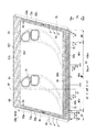
外側シュラウド60oは、図3及び図4に示すように、軸方向Da及び周方向Dcに広がる板状の外側シュラウド本体61と、外側シュラウド本体61の外周縁に沿って外側シュラウド本体61から径方向外側Droに突出する周壁65と、を有する。
As shown in FIGS. 3 and 4, the outer shroud 60 o is formed of a plate-shaped
外側シュラウド本体61は、上流側Dauの端面である前端面62fと、下流側Dadの端面である後端面62bと、周方向腹側Dcpの端面である腹側端面63pと、周方向背側Dcnの端面である背側端面63nと、径方向内側Driを向くガスパス面64と、が形成されている。前端面62fと後端面62bとは、ほぼ平行である。また、腹側端面63pと背側端面63nとは、ほぼ平行である。よって、外側シュラウド本体61は、径方向Dcから見た場合、図4に示すように、平行四辺形状を成している。外側シュラウド60oの腹側端面63pには、背側端面63n側に凹み、腹側端面63pに沿って軸方向Da成分を有する方向に延びるシール溝77が形成されている。また、外側シュラウド60oの背側端面63nには、腹側端面63p側に凹み、背側端面63nに沿って軸方向Da成分を有する方向に延びるシール溝77が形成されている。周方向Dcで隣り合っている二つの静翼50の外側シュラウド60oのうち、一方の静翼50における外側シュラウド60oの腹側端面63pと、他方の静翼50における外側シュラウド60oの背側端面63nとが周方向Dcに隙間78をあけて対向する。一方の静翼50における外側シュラウド60oの腹側端面63pと、他方の静翼50における外側シュラウド60oの背側端面63nとの間には、シール板76が配置されている。このシール板76の周方向Dcの両端は、腹側端面63pに形成されているシール溝77、及び背側端面63nに形成されているシール溝77に嵌り込んでいる。このシール板76は、タービン車室45内の冷却空気又は冷却空気通路42pを通った冷却空気が周方向Dcで隣り合っている二つの静翼50の外側シュラウド60o相互間の隙間78から燃焼ガス流路49に漏れ出すのを防ぐ役目を担っている。
The
周壁65は、軸方向Daで互いに対向する前周壁65f及び後周壁65bと、周方向Dcで互いに対向する一対の側周壁65p,65nと、を有する。前周壁65f及び後周壁65bは、いずれも、外側シュラウド本体61に対して、一対の側周壁65p,65nよりも径方向外側Droに突出しており、フック部を成す。フック部を成す前周壁65f及び後周壁65bは、静翼50をタービン車室45(図2参照)の内周側に取り付ける役目を担う。外側シュラウド60oには、外側シュラウド本体61と周壁65とにより、径方向内側Driに向かって凹む凹部66が形成されている。
The
静翼50は、さらに、外側シュラウド60oの凹部66を径方向外側Droの領域と径方向内側Driの領域である内側キャビティ69(空洞)とに仕切る衝突板67を備えている。この衝突板67には、径方向Drに貫通する複数の空気孔68が形成されている。静翼50の径方向外側Droに存在する冷却空気Acの一部は、この衝突板67の空気孔68を経て、内側キャビティ69内に流入する。
The
翼体51、外側シュラウド60o及び内側シュラウド60iには、径方向Dcに延びる複数の翼空気通路71(空洞)が形成されている。各翼空気通路71は、いずれも、外側シュラウド60oから、翼体51を経て、内側シュラウド60iにまで連なって形成されている。複数の翼空気通路71は、翼体51の翼弦に沿って並んでいる。隣接する翼空気通路71の一部は、径方向外側Droの部分、又は径方向内側Driの部分で互いに連通している。また、複数の翼空気通路71のうち、いずれかは、外側シュラウド60oにおける凹部66の底で開口している。さらに、複数の翼空気通路71のうち、いずれかは、内側シュラウド60iにおける凹部の底で開口している。静翼50の径方向外側Dro又は径方向内側Driに存在する冷却空気Acの一部は、この翼空気通路71の開口から翼空気通路71内に流入する。
A plurality of blade air passages 71 (cavities) extending in the radial direction Dc are formed in the
翼体51の前縁部52及び後縁部53には、翼空気通路71から燃焼ガス流路49へ貫通する複数の翼面噴出通路72が形成されている。翼体51は、翼空気通路71内を冷却空気Acが流れる過程で冷却される。また、翼空気通路71に流入した冷却空気Acは、この翼面噴出通路72から燃焼ガス流路49内に流出する。このため、翼体51の前縁部52及び後縁部53は、冷却空気Acが翼面噴出通路72から流出する過程で冷却される。さらに、翼面噴出通路72から燃焼ガス流路49に流出した冷却空気Acの一部は、翼体51の表面を部分的に覆ってフィルム空気としての役目も果たす。
A plurality of blade
図4に示すように、外側シュラウド60oの一対の側周壁65p,65nのうち、腹側の側周壁65pには、腹側端面63pに沿って軸方向Da成分を有する方向に延びる腹側通路73pが形成されている。また、背側の側周壁65nには、背側端面63nに沿って軸方向Da成分を有する方向に延びる背側通路73nが形成されている。腹側通路73p及び背側通路73nは、いずれも、その上流端で内側キャビティ69に連通している。また、腹側通路73p及び背側通路73nは、いずれも、その下流端で外側シュラウド本体61の後端面62bで開口している。外側シュラウド本体61には、後端面62bに沿って周方向Dcに延びる後ヘッダ通路74が形成されている。この後ヘッダ通路74の周方向腹側Dcpの端は、腹側通路73pに接続されている。また、この後ヘッダ通路74の周方向背側Dcnの端は、背側通路73nに接続されている。すなわち、後ヘッダ通路74は、腹側通路73p及び背側通路73nと連通している。さらに、外側シュラウド本体61には、後ヘッダ通路74から下流側Dadに延び、後端面62bで開口する複数の後通路75が形成されている。複数の後通路75は、周方向Dcに並んでいる。腹側通路73p及び背側通路73n中で、後ヘッダ通路74と連通している位置よりも下流側Dadの部分は、後端面62bで開口する後通路75を成す。
4, among the pair of side
腹側通路73p、背側通路73nを含む後通路75の断面形状は、いずれも円形である。腹側通路73p及び背側通路73nを除く後通路75の内径d1は、互いに同じで、腹側通路73p及び背側通路73nの内径d2よりも小さい。よって、腹側通路73p及び背側通路73nを除く後通路75の濡れ縁長さs1は、互いに同じで、腹側通路73p及び背側通路73nの濡れ縁長さs2より短い。なお、濡れ縁長さsとは、流路断面で流体に接している壁面の長さである。例えば、流路断面が円形の場合、濡れ縁長さsはこの円の円周長である。
The cross-sectional shape of the
ここで、外側シュラウド本体61の後端面62b中で、背側端面63nとの縁及び腹側端面63pの縁を含まない領域を中領域MPとする。また、後端面62b中で背側端面63nとの縁を含み中領域MPと周方向Dcで隣接する領域を背側領域NPとする。さらに、後端面62b中で腹側端面63pとの縁を含み中領域MPと周方向Dcで隣接する領域を腹側領域PPとする。各領域MP,NP,PPには、周方向Dcに並ぶ3以上の後通路75の開口が形成されている。
Here, in the
中領域MPにおける複数の後通路75の開口の間隔は、p1である。背側領域NPにおける複数の後通路75の開口の間隔、及び、腹側領域PPにおける複数の後通路75の開口の間隔は、p2である。中領域MPにおける複数の後通路75の開口の間隔p1は、背側領域NP及び腹側領域PPにおける複数の後通路75の開口の間隔p2より小さい。
The interval between the openings of the plurality of
このため、複数の後通路75の開口の間隔pに対する複数の後通路75の濡れ縁長さsの割合を開口密度(s/p)とすると、図5に示すように、中領域MPにおける複数の後通路75の開口密度a1(=s1/p1)は、腹側領域PP及び背側領域NPにおける複数の後通路75の開口密度a2(=s1/p2又はs2/p2)よりも高い。
For this reason, when the ratio of the wet edge length s of the plurality of
内側キャビティ69内に流入した冷却空気Acは、腹側通路73p及び背側通路73nに流入する。腹側通路73pに流入した冷却空気Acは、ここを流れる過程で、外側シュラウド本体61の腹側端面63p寄りの部分を冷却する。また、背側通路73nに流入した冷却空気Acは、ここを流れる過程で、外側シュラウド本体61の背側端面63n寄りの部分を冷却する。
The cooling air Ac that has flowed into the
腹側通路73p及び背側通路73nに流入した冷却空気Acの一部は、後ヘッダ通路74に流入する。後ヘッダ通路74に流入した冷却空気Acは、複数の後通路75に流入する。後通路75に流入した冷却空気Acは、外側シュラウド60oの後端面62bから外部に流出する。冷却空気Acは、腹側通路73p及び背側通路73nを含む後通路75を流れる過程で、外側シュラウド本体61の後端面62b寄りの部分を冷却する。
Part of the cooling air Ac that has flowed into the
図4に示すように、翼体51の背側面54に沿って流れる燃焼ガスGの流路長は、翼体51の腹側面55に沿って流れる燃焼ガスGの流路長よりも長い。このため、翼体51の背側面54に沿って流れる燃焼ガスGの流速は、翼体51の腹側面55に沿って流れる燃焼ガスGの流速よりも速い。また、翼体51の背側面54に沿って流れた燃焼ガスGは、その後、外側シュラウド60oのガスパス面64中の後端面62b寄りの部分で且つ周方向Dcの中央部分でも、速い流速が維持される。よって、翼体51の背側面54、及び外側シュラウド60oのガスパス面64中の後端面62b寄りの部分で且つ周方向Dcの中央部分は、燃焼ガスGとの熱伝達率が高くなり、他の部分に比べて燃焼ガスGにより加熱される。
As shown in FIG. 4, the flow path length of the combustion gas G flowing along the
また、腹側通路73p及び背側通路73nから後ヘッダ通路74に流入した冷却空気Acは、腹側通路73p及び背側通路73nから遠ざかるに連れて、燃焼ガスGとの熱交換で次第に加熱される。すなわち、後ヘッダ通路74中を流れる冷却空気Acの温度は、腹側通路73p及び背側通路73nから遠ざかるに連れて、言い換えると、後ヘッダ通路74の周方向Dcの中央部に近づくに連れて、ガスパス面64に沿って流れる燃焼ガスGからの入熱により次第に高くなる。このため、複数の後通路75のうち、後端面62bの中領域MPで開口している後通路75を流れる冷却空気Acの温度は、後端面62bの腹側領域PP及び背側領域NPで開口している後通路75を流れる冷却空気Acの温度よりも高い。よって、中領域MPで開口している一つの後通路75を流れる冷却空気Acの冷却能力は、腹側領域PP及び背側領域NPで開口している一つの後通路75を流れる冷却空気Acの冷却能力よりも低い。
Further, the cooling air Ac flowing into the
以上のように、外側シュラウド60oのガスパス面64中の後端面62b寄りの部分で且つ周方向Dcの中央部分では、他の部分に比べて燃焼ガスGにより加熱され易い。しかも、この中央部分に存在する一つの後通路75を流れる冷却空気Acの冷却能力が、他の部分に存在する一つの後通路75を流れる冷却空気Acの冷却能力よりも低い。逆に、外側シュラウド60oのガスパス面64中の後端面62b寄りの部分で且つ周方向Dcの端側部分では、周方向Dcの中央部分に比べて、燃焼ガスGにより加熱され難い。しかも、外側シュラウド60oのガスパス面64中の後端面62b寄りの部分で且つ周方向Dcの端側部分に存在する一つの後通路75を流れる冷却空気Acの冷却能力が、周方向Dcの中央部分に存在する一つの後通路75を流れる冷却空気Acの冷却能力よりも高い。
As described above, the portion near the
そこで、本実施形態では、中領域MPにおける複数の後通路75の開口密度a1(=s1/p1)を、腹側領域PP及び背側領域NPにおける複数の後通路75の開口密度a2(=s1/p2又はs2/p2)よりも高めている。この結果、本実施形態では、外側シュラウド60oのガスパス面64中の後端面62b寄りの部分で且つ周方向Dcの中央部分における冷却能力を高めることができ、翼の耐久性を向上させることができる。さらに、本実施形態では、外側シュラウド60oのガスパス面64中の後端面62b寄りの部分で且つ周方向Dcの端側部分に存在する複数の後通路75を流れる冷却空気Acの総流量を抑えることができる。
Therefore, in this embodiment, the opening density a1 (= s1 / p1) of the plurality of
前述したように、後ヘッダ通路74中を流れる冷却空気Acは、腹側通路73p及び背側通路73nから遠ざかるに連れて、次第にヒートアップされて、冷却能力が低下する。しかしながら、本実施形態では、冷却能力が低下した冷却空気Acを使い回すことで、冷却空気量の低減という優れた効果を得ることができる。すなわち、前述のように、衝突板67の空気孔68を経て、内側キャビティ69内に流入した冷却空気Acは、内側キャビティ69を形成する面に衝突して、この面を衝突冷却する。この結果、この面と対向するガスパス面64は冷却される。さらに、衝突冷却後の冷却空気Acは、腹側通路73p及び背側通路73nから後ヘッダ通路74を経て後通路75の後端面62bの開口から燃焼ガス流路49に排出される過程で各通路を対流冷却する。
As described above, the cooling air Ac flowing in the
また、翼体51の形状や、外側シュラウド60oのガスパス面64中での翼体51の後縁部53の相対位置関係等から、外側シュラウド60oのガスパス面64中で翼体51の後縁部53よりも下流側Dadであって腹側端面63に近い腹側領域PPが、翼体51の後縁部53から流出した一部の冷却空気Acにより幾分冷却される。
Further, the rear edge portion of the
よって、本実施形態では、外側シュラウド60oのガスパス面64中の後端面62b寄りの部分を効果的に冷却して、表面温度の上昇を抑制し、この外側シュラウド60oの耐久性を向上させつつ、この部分を冷却するための冷却空気Acの流量を抑えることができる。また、本実施形態では、前述したように、冷却空気Acを使い回すことにより、冷却空気Acの流量をさらに抑えることができる。よって、本実施形態では、冷却空気Acの流量低減により、ガスタービン全体の熱効率を向上させることができる。
Therefore, in this embodiment, the portion near the
なお、図5では、腹側領域PP及び背側領域NPにおける複数の後通路75の開口密度a2(=s1/p2又はs2/p2)を、これらの領域PP,NP内で一定にしているが、開口密度a2が開口密度a1を下回る限り、これらの領域PP,NP内で多少異なってもよい。腹側領域PP及び背側領域NPには、複数の後通路75の一部である腹側通路73p及び背側通路73nと、これらの通路73p,73nと内径が異なる後通路75とが混在する。このため、腹側領域PP及び背側領域NPにおける複数の後通路75の開口密度は、これらの領域PP,NP内で多少異なる可能性がある。よって、以下の実施形態においても、腹側領域PP及び背側領域NPにおける複数の後通路75の開口密度は、これらの領域PP,NP内で多少異なってもよい。
In FIG. 5, the opening density a2 (= s1 / p2 or s2 / p2) of the plurality of
また、以上の実施形態において、腹側通路73p及び背側通路73nにおける後ヘッダ通路74より下流側Dauに延びている部分を成す後通路75の内径d2は、中領域MPの後通路75の内径d1より大きい。しかしながら、腹側通路73p及び背側通路73nにおける後ヘッダ通路74より下流側Dauに延びている部分を成す後通路75の内径d2は、中領域MPの後通路75の内径d1と同じであってもよい。但し、腹側通路73p又は背側通路73nを流れる冷却空気中に含まれる錆等の異物で、下流側Dauの後通路75が閉塞しないように、さらに、異物を下流側Dauに排出し易くするために、本実施形態のように、腹側通路73p及び背側通路73nにおける後ヘッダ通路74より下流側Dauに延びている部分を成す後通路75の内径d2が、中領域MPの後通路75の内径d1より大きいことが望ましい。
Further, in the above embodiment, the inner diameter d2 of the
以上の説明は、外側シュラウド60oを対象とした説明であるが、内側シュラウド60iも同様に説明できる。
The above description is for the outer shroud 60o, but the
「翼の第二実施形態」
以下、本発明に係る翼の第二実施形態について、図6及び図7を参照して説明する。"Second embodiment of the wing"
Hereinafter, a second embodiment of the wing according to the present invention will be described with reference to FIGS. 6 and 7.
本実施形態の翼も、ガスタービンの静翼である。本実施形態の静翼は、第一実施形態における外側シュラウド60o及び内側シュラウド60iの冷却空気Acが通る通路を変更したもので、その他の構成は、第一実施形態の翼と同様である。
The blade of this embodiment is also a stationary blade of a gas turbine. The stationary blade of this embodiment is obtained by changing the passage through which the cooling air Ac of the outer shroud 60o and the
図6に示すように、本実施形態の外側シュラウド60oにも、第一実施形態の翼と同様、腹側通路73p、背側通路73n、後ヘッダ通路74、及び複数の後通路75が形成されている。
As shown in FIG. 6, the outer shroud 60o of the present embodiment is also formed with an
なお、翼体51の背側面54、及び外側シュラウド60oのガスパス面64中の後端面62b寄りの部分で且つ周方向Dcの中央部分は、燃焼ガスGとの熱伝達率が高くなり、他の部分に比べて燃焼ガスGにより加熱される点は、第一実施形態と同様である。
Note that the
腹側通路73p及び背側通路73nを除く後通路75の内径は、本実施形態においても、d1で、腹側通路73p及び背側通路73nの内径d2よりも小さい。よって、腹側通路73p及び背側通路73nを除く後通路75の濡れ縁長さs1は、腹側通路73p及び背側通路73nの濡れ縁長さs2より短い。
The inner diameter of the
本実施形態では、中領域MPにおける複数の後通路75の開口の間隔は、第一実施形態と同様、p1である。腹側領域PPにおける複数の後通路75の開口の間隔も、第一実施形態と同様、p2(>p1)である。背側領域NPにおける複数の後通路75の開口の間隔は、腹側領域PPにおける複数の後通路75の開口の間隔p2より大きいp3である。
In the present embodiment, the interval between the openings of the plurality of
このため、図7に示すように、中領域MPにおける複数の後通路75の開口密度a1(=s1/p1)は、第一実施形態と同様、腹側領域PPにおける複数の後通路75の開口密度a2(=s1/p2又はs2/p2)よりも高い。また、本実施形態では、背側領域NPにおける複数の後通路75の開口密度a3(=s1/p3又はs2/p3)は、腹側領域PPにおける複数の後通路75の開口密度a2(=s1/p2又はs2/p2)より低い。
For this reason, as shown in FIG. 7, the opening density a1 (= s1 / p1) of the plurality of
周方向Dcで互いに隣接する外側シュラウド60o相互間の隙間78には、第一実施形態と同様、冷却空気Acをシールするシール板76が配置されている。通常の運転状態では、燃焼ガスGがガスタービン車室15側に流れるのを防止するため、ガスタービン車室15及び冷却空気通路42pの空気の圧力は、燃焼ガス流路49を流れる燃焼ガスGの圧力より高くなるように調整されている。従って、通常の運転状態では、常時少量の冷却空気Acが、隣接する外側シュラウド60o相互間の隙間78を通って燃焼ガス流路49中に流入する。この際、冷却空気Acは、隣接する外側シュラウド60o相互間の隙間78に配置されているシール板76と外側シュラウド60oのシール溝77との間の僅かな隙間を流れる。翼間を流れる燃焼ガスGは、翼体51の背側面54及び腹側面55に沿って流れる。前述のように、背側面54に沿って流れる燃焼ガスGの流速は、腹側面55に沿って流れる燃焼ガスGの流速より速い。そのため、背側面54に沿って燃焼ガスGが流れる背側の流域は、腹側面55の沿う腹側の流域より圧力(静圧)が低くなる。従って、隙間78を経由して燃焼ガスG中に漏れ出した冷却空気Acと背側の流域を流れる燃焼ガスGとの差圧は、隙間78から漏れ出した冷却空気Acと腹側の流域を流れる燃焼ガスとの差圧よりも大きい。そのため、隙間78を経由して燃焼ガスG中に漏れ出した大半の冷却空気Acは、ガスパス面64に沿って、圧力の低い下流側の背側の流域に流入する。よって、外側シュラウド60oのガスパス面64中の後端面62b寄りの部分で且つ周方向背側Dcnの部分は、燃焼ガス流路49内に流入した冷却空気Acの影響を受けて、外側シュラウド60oのガスパス面64中の後端面62b寄りの部分で且つ周方向腹側Dcpの部分よりも、冷却される。
In the
腹側通路73p及び背側通路73nに流入した冷却空気Acは、第一実施形態と同様に、後ヘッダ通路74に流入し、複数の後通路75を介して、外側シュラウド60oの後端面62bから外部に流出する。この際、冷却空気Acが後ヘッダ通路74を流れる過程でヒートアップされ、冷却空気Acの冷却能力が低下するのは、第一実施形態と同様である。
The cooling air Ac that has flowed into the
前述したように、本実施形態では、外側シュラウド60oのガスパス面64中の後端面62b寄りの部分で且つ周方向背側Dcnの部分は、外側シュラウド60oのガスパス面64中の後端面62b寄りの部分で且つ周方向腹側Dcpの部分よりも、冷却される。そこで、本実施形態では、背側領域NPにおける複数の後通路75の開口密度a3(=s1/p3又はs2/p3)を、腹側領域PPにおける複数の後通路75の開口密度a2(=s1/p2又はs2/p2)より低くしている。この結果、本実施形態では、外側シュラウド60oのガスパス面64中の後端面62b寄りの部分で且つ周方向Dcの端側部分に存在する複数の後通路75を流れる冷却空気Acの総流量を抑えることができる。
As described above, in this embodiment, the portion near the
なお、前述のように、通常の運転状態では、常時少量の冷却空気Acが隣接する外側シュラウド60o相互間の隙間78を通って燃焼ガス流路49中に流入するのは、第一実施形態も同様である。但し、通常の運転状態におけるシール溝77内のシール板76の配置又は姿勢によっては、シール溝77とシール板76との僅かな隙間から燃焼ガス流路49へ流れ出す空気量が増大する場合がある。このような場合に適用されるのが、本実施形態である。
As described above, in a normal operation state, a small amount of the cooling air Ac always flows into the
「翼の第三実施形態」
以下、本発明に係る翼の第三実施形態について、図8及び図9を参照して説明する。"Third embodiment of wing"
Hereinafter, a third embodiment of the wing according to the present invention will be described with reference to FIGS. 8 and 9.
本実施形態の翼も、ガスタービンの静翼である。本実施形態の静翼は、第一実施形態における外側シュラウド60o及び内側シュラウド60iの冷却空気Acが通る通路を変更したもので、その他の構成は、第一実施形態の翼と同様である。
The blade of this embodiment is also a stationary blade of a gas turbine. The stationary blade of this embodiment is obtained by changing the passage through which the cooling air Ac of the outer shroud 60o and the
図8に示すように、本実施形態の外側シュラウド60oにも、第一実施形態の翼と同様、腹側通路73p、背側通路73n、後ヘッダ通路74、及び複数の後通路75が形成されている。
As shown in FIG. 8, the outer shroud 60o of the present embodiment is also formed with an
腹側通路73p及び背側通路73nを除く後通路75の内径は、本実施形態においても、d1で、腹側通路73p及び背側通路73nの内径d2よりも小さい。よって、腹側通路73p及び背側通路73nを除く後通路75の濡れ縁長さs1は、腹側通路73p及び背側通路73nの濡れ縁長さs2より短い。
The inner diameter of the
本実施形態では、中領域MPにおける複数の後通路75の開口の間隔は、第一実施形態と同様、p1である。背側領域NPにおける複数の後通路75の開口の間隔も、第一実施形態と同様、p2(>p1)である。腹側領域PPにおける複数の後通路75の開口の間隔は、中領域MPにおける複数の後通路75の開口の間隔p1と同じp1である。
In the present embodiment, the interval between the openings of the plurality of
このため、図9に示すように、中領域MPにおける複数の後通路75の開口密度a1(=s1/p1)は、第一実施形態と同様、背側領域NPにおける複数の後通路75の開口密度a2(=s1/p2又はs2/p2)よりも高い。また、本実施形態では、腹側領域PPにおける複数の後通路75の開口密度a1(=s1/p1又はs2/p1)は、中領域MPにおける複数の後通路75の開口密度a1(=s1/p1)と実質的に同じである。よって、腹側領域PPにおける複数の後通路75の開口密度a1(=s1/p1又はs2/p1)は、背側領域NPにおける複数の後通路75の開口密度a2(=s1/p2又はs2/p2)よりも高い。
For this reason, as shown in FIG. 9, the opening density a1 (= s1 / p1) of the plurality of
図3を用いて前述したように、翼体51の翼空気通路71から翼体51の翼面噴出通路72に流入した空気は、翼体51の前縁部52及び後縁部53から燃焼ガス流路49中に流出する。翼体51の後縁部53から流出した冷却空気Acの一部は、翼体51のみならず、外側シュラウド60oのガスパス面64中で翼体51の後縁部53よりも下流側Dadの部分を冷却する。しかしながら、第一実施形態と異なり、翼体51の形状や、外側シュラウド60oのガスパス面64中での翼体51の後縁部53の相対位置関係等から、翼体51の後縁部53から流出した冷却空気Acの一部で、外側シュラウド60oのガスパス面64中で翼体51の後縁部53よりも下流側Dadの部分をあまり冷却できない場合もある。
As described above with reference to FIG. 3, the air flowing from the
本実施形態では、このような場合を考慮して、腹側領域PPにおける複数の後通路75の開口密度a1(=s1/p1又はs2/p1)を、背側領域NPにおける複数の後通路75の開口密度a2(=s1/p2又はs2/p2)よりも高くしている。この結果、本実施形態では、翼体51の形状や、外側シュラウド60oのガスパス面64中での翼体51の後縁部53の相対位置関係等から、翼体51の後縁部53から流出した冷却空気Acの一部で、外側シュラウド60oのガスパス面64中で翼体51の後縁部53よりも下流側Dadの部分をあまり冷却できない場合でも、この部分を腹側領域PPにおける複数の後通路75を流れる冷却空気Acにより冷却することができる。
In the present embodiment, in consideration of such a case, the opening density a1 (= s1 / p1 or s2 / p1) of the plurality of
なお、本実施形態では、腹側領域PPにおける複数の後通路75の開口密度a1(=s1/p1又はs2/p1)は、中領域MPにおける複数の後通路75の開口密度a1(=s1/p1)と実質的に同じである。しかしながら、腹側領域PPにおける複数の後通路75の開口密度は、中領域MPにおける複数の後通路75の開口密度a1(=s1/p1)より低く、背側領域NPにおける複数の後通路75の開口密度a2(=s1/p2又はs2/p2)よりも高くしてもよい。すなわち、腹側領域PPにおける複数の後通路75の開口密度と、中領域MPにおける複数の後通路75の開口密度(a1=s1/p1)とは、同じである必要はない。
In the present embodiment, the opening density a1 (= s1 / p1 or s2 / p1) of the plurality of
また、本実施形態は、第一実施形態の変形例としての実施形態であるが、第二実施形態においても、本実施形態と同様、腹側領域PPにおける複数の後通路75の開口密度を、中領域MPにおける複数の後通路75の開口密度a1(=s1/p1)と実質的に同じにしてもよい。
Moreover, although this embodiment is embodiment as a modification of 1st embodiment, also in 2nd embodiment, similarly to this embodiment, the opening density of the plurality of
「翼の第四実施形態」
以下、本発明に係る翼の第四実施形態について、図10を参照して説明する。"Fourth embodiment of wing"
Hereinafter, a fourth embodiment of the wing according to the present invention will be described with reference to FIG.
本実施形態の翼も、ガスタービンの静翼である。本実施形態の静翼は、第二実施形態における外側シュラウド60o及び内側シュラウド60iの冷却空気Acが通る通路を変更したもので、その他の構成は、第二実施形態の翼と同様である。
The blade of this embodiment is also a stationary blade of a gas turbine. The stationary blade of this embodiment is obtained by changing the passage through which the cooling air Ac of the outer shroud 60o and the
図10に示すように、本実施形態の外側シュラウド60oにも、第二実施形態の翼と同様、腹側通路73p、背側通路73n、及び複数の後通路75aが形成されている。但し、本実施形態の外側シュラウド60oには、第二実施形態における後ヘッダ通路74がない。このため、複数の後通路75aは、それぞれ、外側シュラウド60oの内側キャビティ69と連通し、この内側キャビティ69から直接冷却空気Acが流入するようになっている。
As shown in FIG. 10, the outer shroud 60o of the present embodiment is also formed with an
腹側通路73p及び背側通路73nを除く後通路75aの内径は、本実施形態においても、d1で、腹側通路73p及び背側通路73nの内径d2よりも小さい。よって、腹側通路73p及び背側通路73nを除く後通路75aの濡れ縁長さs1は、腹側通路73p及び背側通路73nの濡れ縁長さs2より短い。
The inner diameter of the rear passage 75a excluding the
本実施形態では、中領域MPにおける複数の後通路75aの開口の間隔p1、腹側領域PPにおける複数の後通路75aの開口の間隔p2、及び、背側領域NPにおける複数の後通路75aの開口の間隔p3は、いずれも第二実施形態と同様である。 In the present embodiment, the intervals p1 of the openings of the plurality of rear passages 75a in the middle region MP, the intervals p2 of the openings of the plurality of rear passages 75a in the ventral region PP, and the openings of the plurality of rear passages 75a in the dorsal region NP. The interval p3 is the same as that in the second embodiment.
このため、本実施形態では、中領域MPにおける複数の後通路75aの開口密度a1(=s1/p1)、腹側領域PPにおける複数の後通路75aの開口密度a2(=s1/p2又はs2/p2)、背側領域NPにおける複数の後通路75aの開口密度a3(=s1/p3又はs2/p3)は、いずれも第二実施形態と同様である。 For this reason, in the present embodiment, the opening density a1 (= s1 / p1) of the plurality of rear passages 75a in the middle region MP, and the opening density a2 (= s1 / p2 or s2 /) of the plurality of rear passages 75a in the ventral region PP. p2) The opening density a3 (= s1 / p3 or s2 / p3) of the plurality of rear passages 75a in the back region NP is the same as that of the second embodiment.
従って、本実施形態でも、第二実施形態と実質的に同様の効果を得ることができる。 Therefore, in the present embodiment, substantially the same effect as that of the second embodiment can be obtained.
また、本実施形態では、複数の後通路75aに流入する冷却空気Acが、第二実施形態のように腹側通路73p又は背側通路73n及び後ヘッダ通路74を経ずに、内側キャビティ69から流入する。すなわち、本実施形態では、第二実施形態とは異なり、衝突板67の空気孔68を経て内側キャビティ69内に流入した冷却空気Acは、内側キャビティ69を形成する面に衝突して、この面を衝突冷却した後、直接内側キャビティ69から後通路75に流入する。従って、本実施形態では、後通路75に流入する冷却空気Acが、第一及び第二実施形態の後ヘッダ通路74内を流れる冷却空気Acのようにはヒートアップしない。このため、本実施形態では、複数の後通路75aに流入する冷却空気Acの温度が、第二実施形態で複数の後通路75に流入する冷却空気Acの温度よりも低い。よって、本実施形態では、第二実施形態よりも、外側シュラウド60oのガスパス面64中の後端面62b寄りの部分を冷却することができる。
In the present embodiment, the cooling air Ac flowing into the plurality of rear passages 75a does not pass through the
このように、複数の後通路75aに流入する冷却空気Acは、第二実施形態のように腹側通路73p又は背側通路73n及び後ヘッダ通路74を経なくてもよい。例えば、外側シュラウド60o、翼体51、内側シュラウド60i内に連なって形成されている複数の翼空気通路71(空洞)のいずれかに、複数の後通路のそれぞれを直接連通させてもよい。
As described above, the cooling air Ac flowing into the plurality of rear passages 75a may not pass through the
なお、本実施形態は、第二実施形態の変形例としての実施形態であるが、第一及び第三実施形態においても、その変形例として、複数の後通路を内側キャビティ69(空洞)や翼空気通路71(空洞)と直接連通させてよい。 In addition, although this embodiment is embodiment as a modification of 2nd embodiment, also in 1st and 3rd embodiment, as a modification, several back passages are made into the inner cavity 69 (cavity) and wing | blade. The air passage 71 (cavity) may be in direct communication.
「翼の第五実施形態」
以下、本発明に係る翼の第五実施形態について、図11及び図13を参照して説明する。"Fifth embodiment of wing"
Hereinafter, a fifth embodiment of the wing according to the present invention will be described with reference to FIGS. 11 and 13.
第五実施形態の翼も、ガスタービンの静翼である。第五実施形態の静翼は、第一実施形態における二つの静翼を一体化したものである。 The blade of the fifth embodiment is also a stationary blade of a gas turbine. The stationary blade of the fifth embodiment is obtained by integrating the two stationary blades of the first embodiment.
図11に示すように、第五実施形態の静翼50aは、第一実施形態における二つの静翼50の外側シュラウド60o相互をボルト及びナットで連結すると共に、内側シュラウド60i相互をボルト79b及びナット79nで連結したものである。この結果、二つの静翼50の外側シュラウド60oが一体化する共に、二つの静翼50の内側シュラウド60iが一体化する。このように、二つの静翼50をボルト79b及びナット79nで連結したものを結合静翼と呼ぶことがあるが、ここでは、単に静翼50aと呼ぶ。
As shown in FIG. 11, the
本実施形態では、第一実施形態における二つの静翼50の外側シュラウド60oが一体化したものを単に外側シュラウド60oaと呼び、第一実施形態における二つの静翼50の各外側シュラウド60oを分割外側シュラウド部60ocと呼ぶ。また、第一実施形態における二つの静翼50の内側シュラウド60iが一体化したものを単に内側シュラウドと呼び、第一実施形態における二つの静翼50の各内側シュラウド60iを分割内側シュラウド部と呼ぶ。このため、本実施形態の静翼50aでは、一つの外側シュラウド60oa及び一つの内側シュラウドに対して、二つの翼体51が設けられていることになる。さらに、本実施形態では、第一実施形態における二つの静翼50の外側シュラウド本体61が一体化したものを単に外側シュラウド本体61aと呼ぶ。
In this embodiment, what integrated the outer shroud 60o of the two
なお、一体化された複数の分割外側シュラウド部60ocの相互間、又は一体化された複数の分割内側シュラウドの相互間には、第一実施形態のようなシール板が存在せず、両者は隙間なく周方向Dcに締結されている。但し、複数の分割外側シュラウド部60ocを一体化した外側シュラウド60oaと、これに周方向Dcに隣接して配置される外側シュラウド60oaとの間には、第一実施形態と同様に、隙間が形成され、シール板が配置されている。分割内側シュラウドの場合も同様である。 Note that there is no seal plate as in the first embodiment between the plurality of integrated divided outer shroud portions 60 oc or between the plurality of integrated divided inner shrouds. And is fastened in the circumferential direction Dc. However, a gap is formed between the outer shroud 60oa integrated with the plurality of divided outer shroud portions 60oc and the outer shroud 60oa disposed adjacent to the outer shroud 60c in the circumferential direction Dc. The seal plate is arranged. The same applies to the split inner shroud.
分割外側シュラウド部60ocの構成は、第一実施形態の外側シュラウド60oの構成と基本的に同じである。このため、各分割外側シュラウド部60ocには、腹側通路73p、背側通路73n、後ヘッダ通路74、及び複数の後通路75が形成されている。
The configuration of the divided outer shroud portion 60 oc is basically the same as the configuration of the outer shroud 60 o of the first embodiment. For this reason, an
本実施形態においても、外側シュラウド本体61aの後端面62b中で、背側端面63nとの縁及び腹側端面63pの縁を含まない中領域MPとする。また、後端面62b中で背側端面63nとの縁を含み中領域MPと周方向Dcで隣接する背側領域NPとする。また、後端面62b中で腹側端面63pとの縁を含み中領域MPと周方向Dcで隣接する腹側領域PPとする。さらに、本実施形態では、中領域MP中で二つの翼体51の相互間を含む領域を翼間領域MPbとし、中領域MP中で翼体51に対する軸方向下流側Dadであって翼間領域MPbを除く領域を翼下流領域MPdとする。各領域MPb,MPd,NP,PPには、周方向Dcに並ぶ3以上の後通路75の開口が形成されている。
Also in the present embodiment, in the
腹側通路73p及び背側通路73nを除く後通路75の内径は、本実施形態においても、d1で、腹側通路73p及び背側通路73nの内径d2よりも小さい。よって、腹側通路73p及び背側通路73nを除く後通路75の濡れ縁長さs1は、腹側通路73p及び背側通路73nの濡れ縁長さs2より短い。
The inner diameter of the
本実施形態において、腹側領域PP及び背側領域NPにおける複数の後通路75の開口の間隔は、p2である。中領域MP中の翼下流領域MPdにおける複数の後通路75の開口の間隔は、p1(<p2)である。中領域MP中の翼間領域MPbにおける複数の後通路75の開口の間隔は、p4である。この翼間領域MPbにおける複数の後通路75の開口の間隔p4は、翼下流領域MPdにおける複数の後通路75の開口の間隔p1より大きく、腹側領域PP及び背側領域NPにおける複数の後通路75の開口の間隔p2より小さい。
In the present embodiment, the interval between the openings of the plurality of
このため、図13に示すように、中領域MP中の翼下流領域MPdにおける複数の後通路75の開口密度a1(=s1/p1)は、腹側領域PP及び背側領域NPにおける複数の後通路75の開口密度a2(=s1/p2又はs2/p2)よりも高い。また、本実施形態では、中領域MP中で翼間領域MPbにおける複数の後通路75の開口密度a4(=s1/p4又はs2/p4)は、中領域MP中の翼下流領域MPdにおける複数の後通路75の開口密度a1(=s1/p1)より低く、腹側領域PP及び背側領域NPにおける複数の後通路75の開口密度a2(=s1/p2又はs2/p2)より高い。
For this reason, as shown in FIG. 13, the opening density a1 (= s1 / p1) of the plurality of
本実施形態では、外側シュラウド60oaのガスパス面64中の後端面62b寄りの部分で且つ周方向Dcの端側部分を除く外側シュラウド60oaの中央部分は、第一実施形態と同様に、翼体51の背側面54に沿って流れる燃焼ガスGの影響により、燃焼ガスGとの熱伝達率が高くなり、周方向Dcに隣接する他の部分に比べて燃焼ガスGにより加熱される。この領域が、翼下流領域MPdに相当する。一方、この翼下流領域MPdと周方向Dcに隣接する部分で、翼体51の背側面54に沿って流れる燃焼ガスGにより加熱されるガスパス面64中の後端面62b寄りの部分である領域は、翼体51の後縁部53から流出する冷却空気Acにより幾分冷却される。この領域が、翼間領域MPbに相当する。
In the present embodiment, the central portion of the outer shroud 60oa except for the end side portion in the circumferential direction Dc in the portion near the
そこで、本実施形態では、中領域MP中で翼間領域MPbにおける複数の後通路75の開口密度a4(=s1/p4又はs2/p4)を、中領域MP中の翼下流領域MPdにおける複数の後通路75の開口密度a1(=s1/p1)より低くしている。この結果、本実施形態では、外側シュラウド60oaのガスパス面64中の後端面62b寄りの部分に存在する複数の後通路75を流れる冷却空気Acの総流量を抑えることができる。
Therefore, in the present embodiment, the opening density a4 (= s1 / p4 or s2 / p4) of the plurality of
「翼の第六実施形態」
以下、本発明に係る翼の第六実施形態について、図12及び図13を参照して説明する。"Sixth embodiment of wing"
Hereinafter, a sixth embodiment of the wing according to the present invention will be described with reference to FIGS. 12 and 13.
第六実施形態の翼も、ガスタービンの静翼である。第六実施形態の静翼も、第五実施形態と同様、第一実施形態における二つの静翼を一体化したものである。 The blade of the sixth embodiment is also a stationary blade of a gas turbine. Similarly to the fifth embodiment, the stationary blade according to the sixth embodiment is obtained by integrating the two stationary blades according to the first embodiment.
但し、本実施形態の静翼50bは、図12に示すように、第一実施形態における二つの静翼50の外側シュラウド60o相互をボルト及びナットで連結したものではなく、二つの静翼50を一体鋳造したものである。このように、二つの静翼50を一体鋳造したものを静翼セグメントと呼ぶことがあるが、ここでは、単に静翼50bと呼ぶ。このため、本実施形態の静翼50bでは、一つの外側シュラウド60ob及び一つの内側シュラウドに対して、二つの翼体51が設けられていることになる。
However, as shown in FIG. 12, the
本実施形態の外側シュラウド60obも、第一実施形態の外側シュラウド60oと同様、外側シュラウド本体61b、前周壁65f、後周壁65b、及び一対の側周壁65p,65nと、を有する。但し、本実施形態の外側シュラウド60obには、第五実施形態の外側シュラウド60obにおける二つの翼体51の相互間の側周壁65p,65nは設けられていない。
Similarly to the outer shroud 60o of the first embodiment, the outer shroud 60ob of the present embodiment also includes an outer shroud
本実施形態の外側シュラウド60obにも、第一実施形態の外側シュラウド60oと同様に、腹側通路73p、背側通路73n、後ヘッダ通路74、及び複数の後通路75が形成されている。
Similarly to the outer shroud 60o of the first embodiment, the outer shroud 60ob of the present embodiment is also formed with an
本実施形態においても、外側シュラウド本体61bの後端面62b中で、背側端面63nとの縁及び腹側端面63pの縁を含まない中領域MPとする。また、後端面62b中で背側端面63nとの縁を含み中領域MPと周方向Dcで隣接する背側領域NPとする。また、後端面62b中で腹側端面63pとの縁を含み中領域MPと周方向Dcで隣接する腹側領域PPとする。さらに、本実施形態では、第五実施形態と同様、中領域MP中で二つの翼体51の相互間を含む領域を翼間領域MPbとし、中領域MP中で翼体51に対する軸方向下流側Dadであって翼間領域MPbを除く領域を翼下流領域MPdとする。各領域MPb,MPd,NP,PPには、周方向Dcに並ぶ3以上の後通路75の開口が形成されている。
Also in this embodiment, in the
腹側通路73p及び背側通路73nを除く後通路75の内径は、本実施形態においても、d1で、腹側通路73p及び背側通路73nの内径d2よりも小さい。よって、腹側通路73p及び背側通路73nを除く後通路75の濡れ縁長さs1は、腹側通路73p及び背側通路73nの濡れ縁長さs2より短い。
The inner diameter of the
本実施形態において、各領域MPb,MPd,NP,PPにおける複数の後通路75の開口の間隔は、第五実施形態と同じである。すなわち、本実施形態において、腹側領域PP及び背側領域NPにおける複数の後通路75の開口の間隔は、p2である。中領域MP中の翼下流領域MPdにおける複数の後通路75の開口の間隔は、p1(<p2)である。中領域MP中の翼間領域MPbにおける複数の後通路75の開口の間隔は、p4である。この翼間領域MPbにおける複数の後通路75の開口の間隔p4は、翼下流領域MPdにおける複数の後通路75の開口の間隔p1より大きく、腹側領域PP及び背側領域NPにおける複数の後通路75の開口の間隔p2より小さい。
In the present embodiment, the intervals between the openings of the plurality of
このため、本実施形態においても、図13に示すように、第五実施形態と同様、中領域MP中の翼下流領域MPdにおける複数の後通路75の開口密度a1(=s1/p1)は、腹側領域PP及び背側領域NPにおける複数の後通路75の開口密度a2(=s1/p2又はs2/p2)よりも高い。また、本実施形態では、中領域MP中で翼間領域MPbにおける複数の後通路75の開口密度a4(=s1/p4又はs2/p4)は、中領域MP中の翼下流領域MPdにおける複数の後通路75の開口密度a1(=s1/p1)より低く、腹側領域PP及び背側領域NPにおける複数の後通路75の開口密度a2(=s1/p2又はs2/p2)より高い。
Therefore, also in the present embodiment, as shown in FIG. 13, as in the fifth embodiment, the opening density a1 (= s1 / p1) of the plurality of
よって、本実施形態でも、第五実施形態と同様に、外側シュラウド60obのガスパス面64中の後端面62b寄りの部分に存在する複数の後通路75を流れる冷却空気Acの総流量を抑えることができる。
Therefore, also in this embodiment, as in the fifth embodiment, it is possible to suppress the total flow rate of the cooling air Ac flowing through the plurality of
なお、第五実施形態及び第六実施形態では、いずれも、中領域MP中で翼間領域MPbにおける複数の後通路75の開口密度a4(=s1/p4又はs2/p4)を、中領域MP中の翼下流領域MPdにおける複数の後通路75の開口密度a1(=s1/p1)より低くしている。しかしながら、中領域MP中で翼間領域MPbにおける複数の後通路75の開口密度と、中領域MP中の翼下流領域MPdにおける複数の後通路75の開口密度と、を同じくしてもよい。すなわち、中領域MP中における複数の後通路75の開口密度を一定にしてもよい。
In both the fifth embodiment and the sixth embodiment, the opening density a4 (= s1 / p4 or s2 / p4) of the plurality of
また、第五実施形態及び第六実施形態の静翼は、いずれも、第一実施形態の二つの静翼50を一体化したものであるが、三以上の静翼50を一体化してもよい。
Moreover, although the stator blades of the fifth embodiment and the sixth embodiment are both the two
また、第五実施形態及び第六実施形態の静翼は、いずれも、第一実施形態の静翼50を一体化したものであるが、第二実施形態の静翼を一体化しても、第三実施形態の静翼を一体化してもよい。
The stator blades of the fifth embodiment and the sixth embodiment are both integrated with the
第二実施形態の静翼を一体化した場合、図14に示すように、背側領域NPにおける複数の後通路75の開口密度a3(=s1/p3又はs2/p3)は、腹側領域PPにおける複数の後通路75の開口密度a2(=s1/p2又はs2/p2)より小さくなる。
When the stator blades of the second embodiment are integrated, as shown in FIG. 14, the opening density a3 (= s1 / p3 or s2 / p3) of the plurality of
また、第三実施形態の静翼を一体化した場合、図15に示すように、腹側領域PPにおける複数の後通路75の開口密度a1(=s1/p1又はs2/p1)は、中領域MP中の翼下流領域MPdにおける複数の後通路75の開口密度a1(=s1/p1)と実質的に同じとなる。
Further, when the stationary blades of the third embodiment are integrated, as shown in FIG. 15, the opening density a1 (= s1 / p1 or s2 / p1) of the plurality of
また、第五実施形態及び第六実施形態においても、第四実施形態と同様、複数の後通路75を内側キャビティ69や翼空気通路71と直接連通させてよい。
Also in the fifth embodiment and the sixth embodiment, a plurality of
また、以上の各実施形態の内側シュラウド60iは、前述したように、外側シュラウド60oと基本的構造が同じである。このため、内側シュラウド60iは、軸方向Da及び周方向Dcに広がる板状の内側シュラウド本体と、内側シュラウド本体の外周縁に沿って内側シュラウド本体から径方向内側Driに突出する周壁と、を有する。
Further, as described above, the
「翼の第七実施形態」
以下、本発明に係る翼の第七実施形態について、図16及び図17を参照して説明する。"Seventh embodiment of wing"
Hereinafter, a seventh embodiment of the wing according to the present invention will be described with reference to FIGS. 16 and 17.
本実施形態の翼も、ガスタービンの静翼である。本実施形態の静翼は、第一実施形態における外側シュラウド60o及び内側シュラウド60iに、冷却空気Acが通る通路を追加したもので、その他の構成は、第一実施形態の翼と同様である。
The blade of this embodiment is also a stationary blade of a gas turbine. The stationary blade of this embodiment is obtained by adding a passage through which the cooling air Ac passes to the outer shroud 60o and the
図16に示すように、本実施形態の外側シュラウド60oにも、第一実施形態の翼と同様、腹側通路73p、背側通路73n、後ヘッダ通路74、及び複数の後通路75が形成されている。本実施形態の外側シュラウド60oには、さらに、第一ガスパス面噴出通路81及び第二ガスパス面噴出通路82が形成されている。なお、図16は、外側シュラウド60oを径方向内側Driから見た平面図である。
As shown in FIG. 16, the outer shroud 60o of the present embodiment is also formed with an
複数の第一ガスパス面噴出通路81は、図17に示すように、軸方向Daに延びている。複数の第一ガスパス面噴出通路81の上流側Dauの端は、後ヘッダ通路74につながっている。また、複数の第一ガスパス面噴出通路81の下流側Dadの端は、ガスパス面64で開口している。複数の第一ガスパス面噴出通路81におけるガスパス面64での開口は、翼体51の後縁部53よりも下流側Dadの領域で外側シュラウド60oの後端面62bに沿って並んでいる。よって、複数の第一ガスパス面噴出通路81におけるガスパス面64での開口は、周方向Dcに並んでいる。
The plurality of first gas path surface
複数の第二ガスパス面噴出通路82は、軸方向Daに延びている。複数の第二ガスパス面噴出通路82の上流側Dauの端は、後周壁65bの面であって凹部66に面する内面と、この凹部66の底面との角近傍で開口している。複数の第二ガスパス面噴出通路82の下流側Dadの端は、ガスパス面64で開口している。複数の第二ガスパス面噴出通路82におけるガスパス面64での開口は、翼体51の後縁部53よりも下流側Dadの領域で外側シュラウド60oの後端面62bに沿って並んでいる。よって、複数の第二ガスパス面噴出通路82におけるガスパス面64での開口も、周方向Dcに並んでいる。
The plurality of second gas path surface
複数の第一ガスパス面噴出通路81におけるガスパス面64での開口、及び複数の第二ガスパス面噴出通路82におけるガスパス面64での開口は、いずれも、ガスパス面64中で周方向Dcにおける中領域MPに形成されている。また、複数の第一ガスパス面噴出通路81、及び複数の第二ガスパス面噴出通路82は、いずれも、ガスパス面64に近づく連れて次第に下流側Dadに向くようガスパス面64に対して傾斜している。なお、中領域MPの意義については後述する。
The opening at the gas path surface 64 in the plurality of first gas path surface
後ヘッダ通路74を流れる冷却空気Acの一部は、複数の第一ガスパス面噴出通路81に流入する。複数の第一ガスパス面噴出通路81に流入した冷却空気は、燃焼ガス流路49に流出する。この際、この冷却空気Acは、ガスパス面64に沿って流れ、このガスパス面64をフィルム冷却する。また、内側キャビティ69内の冷却空気Acの一部は、複数の第二ガスパス面噴出通路82に流入する。複数の第二ガスパス面噴出通路82に流入した冷却空気Acは、燃焼ガス流路49に流出する。この際、この冷却空気Acは、ガスパス面64に沿って流れ、このガスパス面64をフィルム冷却する。
A part of the cooling air Ac flowing through the
腹側通路73pからの冷却空気Acは、後ヘッダ通路74の周方向腹側Dcpの端から後ヘッダ通路74内に流入する。この冷却空気Acは、後ヘッダ通路74内を周方向背側Dcnに流れる過程で、順次、複数の後通路75に流入する。また、背側通路73nからの冷却空気Acは、後ヘッダ通路74の周方向背側Dcnの端から後ヘッダ通路74内に流入する。この冷却空気Acは、後ヘッダ通路74内を周方向腹側Dcpに流れる過程で、順次、複数の後通路75に流入する。このため、後ヘッダ通路74における周方向Dcの中領域MPで流れる冷却空気Acの流量は、後ヘッダ通路74における周方向Dcの両端側で流れる冷却空気Acの流量よりも少なくなる。このように、後ヘッダ通路74における周方向Dcの中領域MPで流れる冷却空気Acの流量が少なくなると、後ヘッダ通路74における周方向Dcの中領域MPで流れる冷却空気の流速は、後ヘッダ通路74における周方向Dcの両端側で流れる冷却空気Acの流速よりも少なくなる。従って、後ヘッダ通路74を流れる冷却空気Acと外側シュラウド60oとの間の熱伝達率は、後ヘッダ通路74における周方向Dcの中領域MPが後ヘッダ通路74における周方向Dcの両端側よりも小さくなる。しかも、後ヘッダ通路74を流れる冷却空気Acは、周方向Dcの両端側から周方向Dcの中領域MPに流れる過程で次第に加熱される。このため、後ヘッダ通路74を流れる冷却空気Acによる対流冷却の効果は、周方向Dcの両端側よりも周方向Dcの中領域MPで低くなる。
The cooling air Ac from the
さらに、前述したように、ガスパス面64中の後端面62b寄りの部分で且つ周方向Dcの中領域MPでは、燃焼ガスGとガスパス面64との間の熱伝達率が高なり、他の部分に比べて燃焼ガスGにより加熱され易い。
Furthermore, as described above, in the portion near the
すなわち、ガスパス面64中の後端面62b寄りの部分で且つ周方向Dcの中領域MPでは、後ヘッダ通路74を流れる冷却空気Acによる対流冷却の効果が低い上に、燃焼ガスGにより加熱され易い。
That is, in the portion near the
そこで、本実施形態では、ガスパス面64中の後端面62b寄りの部分で且つ周方向Dcの中領域MPの冷却能力を高めるため、ガスパス面64中の後端面62b寄りの部分で且つ周方向Dcの中領域MPで開口する複数の第一ガスパス面噴出通路81及び複数の第二ガスパス面噴出通路82を設けている。
Therefore, in the present embodiment, in order to increase the cooling capability of the middle region MP in the circumferential direction Dc at the portion near the
なお、本実施形態では、複数の第一ガスパス面噴出通路81と複数の第二ガスパス面噴出通路82とを設けているが、いずれか一方のガスパス面噴出通路のみを設けてもよい。
In the present embodiment, the plurality of first gas path surface
また、本実施形態では、複数の第一ガスパス面噴出通路81におけるガスパス面64での開口は、周方向Dcに一列に並んでいる。しかしながら、周方向Dcに並ぶ開口の列は、複数あってもよい。また、本実施形態では、複数の第二ガスパス面噴出通路82におけるガスパス面64での開口も、周方向Dcに一列に並んでいる。しかしながら、周方向Dcに並ぶこの開口の列も、複数あってもよい。
Moreover, in this embodiment, the opening in the gas path surface 64 in the some 1st gas path surface ejection channel |
また、本実施形態は、第一実施形態の外側シュラウド60oの変形例である。しかしながら、以上の各実施形態及び以下の実施形態における流路形成板に、本実施形態と同様に、複数の第一ガスパス面噴出通路81、及び/又は複数の第二ガスパス面噴出通路82を設けてもよい。
Moreover, this embodiment is a modification of the outer shroud 60o of the first embodiment. However, a plurality of first gas path surface
「翼の第八実施形態」
以下、本発明に係る翼の第八実施形態について、図18及び図19を参照して説明する。"Eighth embodiment of wing"
Hereinafter, an eighth embodiment of a wing according to the present invention will be described with reference to FIGS. 18 and 19.
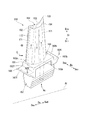
第七実施形態の翼は、以上の各実施形態と異なり、ガスタービンの動翼である。図18に示すように、本実施形態の動翼150は、径方向Drに延びる翼体151と、翼体151の径方向内側Driに形成されているプラットフォーム160と、プラットフォーム160の径方向内側Driに形成されている翼根157と、を有している。翼体151は、燃焼ガス流路49(図2参照)内に配置されている。プラットフォーム160は、環状の燃焼ガス流路49の径方向内側Driの位置を画定する。よって、プラットフォーム160は、燃焼ガス流路49の一部を画定する流路形成板である。
Unlike the above embodiments, the blades of the seventh embodiment are moving blades of a gas turbine. As shown in FIG. 18, the moving
翼体151は、上流側Dauの端部が前縁部152を成し、下流側Dadの端部が後縁部153を成す。この翼体151の表面で、周方向Dcを向く面のうち、凸状の面が背側面154(=負圧面)を成し、凹状の面が腹側面155(=正圧面)を成す。なお、以下の説明の都合上、周方向Dcで翼体151の腹側(=正圧面側)を周方向腹側Dcp、翼体151の背側(=負圧面側)を周方向背側Dcnとする。この動翼150の周方向背側Dcnは、ロータ軸42の回転方向前方側である。一方、先に説明した静翼50の周方向背側Dcnは、ロータ軸42の回転方向後方側である。よって、この動翼150の周方向背側Dcnは、周方向Dcにおいて、静翼50の周方向背側Dcnとは逆側である。また、軸方向Daの上流側Dauを前側、軸方向Daの下流側Dadを後側ということもある。
In the
翼根157は、翼体151の翼弦に対して垂直な断面形状が径方向内側Driに向って拡幅部と縮幅部とが交互に繰り返されるクリスマスツリー形状を成している。前述のロータ軸42には、この翼根157が嵌まり込む翼根溝が形成されている。
The
プラットフォーム160は、軸方向Da及び周方向Dcに広がる板状のプラットフォーム本体161と、プラットフォーム本体161の下流側Dadから下流側Dadに突出する後突出部167bと、プラットフォーム本体161の上流側Dauから上流側Dauに突出する前突出部167fと、を有する。
The
プラットフォーム本体161は、上流側Dauの端面である前端面162fと、下流側Dadの端面である後端面162bと、周方向腹側Dcpの端面である腹側端面163pと、周方向背側Dcnの端面である背側端面163nと、径方向外側Droを向くガスパス面164と、が形成されている。前端面162fと後端面162bとは、ほぼ平行である。また、腹側端面163pと背側端面163nとは、ほぼ平行である。よって、プラットフォーム本体161は、径方向Dcから見た場合、図17に示すように、平行四辺形状を成している。周方向Dcで隣り合っている二つの動翼150のプラットフォーム160のうち、一方の動翼150におけるプラットフォーム160の腹側端面163pと、他方の動翼150におけるプラットフォーム160の背側端面163nとは対向する。また、動翼150の前端面162fは、この動翼150の上流側Dauに隣接する静翼における内側シュラウドの後端面と対向する。動翼150の後端面162bは、この動翼150の下流側Dadに隣接する静翼における内側シュラウドの前端面と対向する。
The
後突出部167bは、プラットフォーム本体161の後端面162bに対して、径方向内側Driにシフトした位置から下流側Dadに突出している。この後突出部167bは、プラットフォーム本体161の後端面162bに沿って形成されている。前突出部167fは、プラットフォーム本体161の前端面162fに対して、径方向内側Driにシフトした位置から上流側Dauに突出している。この前突出部167fは、プラットフォーム本体161の前端面162fに沿って形成されている。
The
動翼150には、径方向Dcに延びる複数の翼空気通路171(空洞)が形成されている。各翼空気通路171は、いずれも、翼体151、プラットフォーム160、翼根157のうち、少なくとも翼体151からプラットフォーム160にかけて連なって形成されている。複数の翼空気通路171は、翼体151の翼弦に沿って並んでいる。隣接する翼空気通路171の一部は、翼体151内の径方向外側Droの部分、又はプラットフォーム160の径方向内側Driの部分で互いに連通している。また、複数の翼空気通路171のうち、いずれかは、翼体151、プラットフォーム160、翼根157にかけて連なって形成されて、翼根157の径方向内側Driの端で開口している。この翼空気通路171には、この開口から、ロータ軸42の冷却空気通路42p(図2参照)を流れて冷却空気Acが流入する。
A plurality of blade air passages 171 (cavities) extending in the radial direction Dc are formed in the moving
翼体151の前縁部152及び後縁部153には、翼空気通路171から燃焼ガス流路49へ貫通する複数の翼面噴出通路172が形成されている。翼体151は、翼空気通路171内を冷却空気Acが流れる過程で冷却される。また、翼空気通路171に流入した冷却空気Acは、この翼面噴出通路172から燃焼ガス流路49内に流出する。このため、翼体151の前縁部152及び後縁部153は、冷却空気Acが翼面噴出通路172を流れる過程で冷却される。さらに、翼面噴出通路172から燃焼ガス流路49に流出した冷却空気Acの一部は、翼体151の表面を部分的に覆ってフィルム空気としての役目も果たす。
A plurality of blade
プラットフォーム本体161には、図19に示すように、複数の翼空気通路171のうち、最も上流側Dauの第一翼空気通路171aと連通している腹側通路173p及び背側通路173nとが形成されている。腹側通路173pは、第一翼空気通路171aから周方向腹側Dcpに向かって、腹側端面163p近くまで延びる周方向通路部173pcと、この周方向通路部173pcの周方向腹側Dcpの端から腹側端面163pに沿って軸方向Da成分を有する方向に延びる軸方向通路部173paとを有する。背側通路173nは、第一翼空気通路171aから周方向背側Dcnに向かって、背側端面163n近くまで延びる周方向通路部173ncと、この周方向通路部173ncの周方向背側Dcnの端から背側端面163nに沿って軸方向Da成分を有する方向に延びる軸方向通路部173naとを有する。腹側通路173p及び背側通路173nは、いずれも、その下流端でプラットフォーム本体161の後端面162bで開口している。プラットフォーム本体161には、後端面162bに沿って周方向Dcに延びる後ヘッダ通路174が形成されている。さらに、プラットフォーム本体161には、後ヘッダ通路174から下流側Dadに延び、後端面162bで開口する複数の後通路175が形成されている。複数の後通路175は、周方向Dcに並んでいる。腹側通路173p及び背側通路173n中で、後ヘッダ通路174と連通している位置よりも下流側Dadの部分は、後端面162bで開口する後通路175を成す。
As shown in FIG. 19, the
腹側通路173p、背側通路173nを含む後通路175の断面形状は、いずれも円形である。腹側通路173p及び背側通路173nを除く後通路175の内径d1は、互いに同じで、腹側通路173p及び背側通路173nの内径d2よりも小さい。よって、腹側通路173p及び背側通路173nを除く後通路175の濡れ縁長さs1は、互いに同じで、腹側通路173p及び背側通路173nの濡れ縁長さs2より短い。
The cross-sectional shape of the
ここで、プラットフォーム本体161の後端面162b中で、背側端面163nとの縁及び腹側端面163pの縁を含まない中領域MPとする。また、後端面162b中で背側端面163nとの縁を含み中領域MPと周方向Dcで隣接する背側領域NPとする。さらに、後端面162b中で腹側端面163pとの縁を含み中領域MPと周方向Dcで隣接する腹側領域PPとする。各領域MP,NP,PPには、周方向Dcに並ぶ3以上の後通路175の開口が形成されている。
Here, in the
中領域MPにおける複数の後通路175の開口の間隔は、p1である。背側領域NPにおける複数の後通路175の開口の間隔、及び腹側領域PPにおける複数の後通路175の開口の間隔は、いずれもp2である。中領域MPにおける複数の後通路175の開口の間隔p1は、背側領域NP及び腹側領域PPにおける複数の後通路175の開口の間隔p2より小さい。
The interval between the openings of the plurality of
このため、図5に示すように、中領域MPにおける複数の後通路175の開口密度a1(=s1/p1)は、腹側領域PP及び背側領域NPにおける複数の後通路175の開口密度a2(=s1/p2又はs2/p2)よりも高い。
Therefore, as shown in FIG. 5, the opening density a1 (= s1 / p1) of the plurality of
動翼150においても、先に説明した静翼と同様、プラットフォーム本体161のガスパス面164中の後端面162b寄りの部分で且つ周方向Dcの中央部分では、他の部分に比べて燃焼ガスGにより加熱され易い。しかも、この中央部分に存在する一つの後通路175を流れる冷却空気Acの冷却能力が、他の部分に存在する一つの後通路175を流れる冷却空気Acの冷却能力よりも低い。逆に、プラットフォーム160のガスパス面164中の後端面162b寄りの部分で且つ周方向Dcの端側部分では、周方向Dcの中央部分に比べて、燃焼ガスGによる加熱量が少ない。しかも、プラットフォーム160のガスパス面164中の後端面162b寄りの部分で且つ周方向Dcの端側部分に存在する一つの後通路175を流れる冷却空気Acの冷却能力が、周方向Dcの中央部分に存在する一つの後通路175を流れる冷却空気Acの冷却能力よりも高い。
In the moving
そこで、本実施形態では、第一実施形態の静翼と同様、中領域MPにおける複数の後通路175の開口密度a1(=s1/p1)を、腹側領域PP及び背側領域NPにおける複数の後通路175の開口密度a2(=s1/p2又はs2/p2)よりも高めている。この結果、本実施形態では、プラットフォーム160のガスパス面164中の後端面162b寄りの部分で且つ周方向Dcの中央部分における冷却能力を高めることができ、翼の耐久性を向上させることができる。さらに、本実施形態では、プラットフォーム160のガスパス面164中の後端面162b寄りの部分で且つ周方向Dcの端側部分に存在する複数の後通路175を流れる冷却空気Acの総流量を抑えることができる。
Therefore, in this embodiment, similarly to the stationary blade of the first embodiment, the opening density a1 (= s1 / p1) of the plurality of
よって、本実施形態では、プラットフォーム160のガスパス面164中の後端面162b寄りの部分を効果的に冷却して、このプラットフォーム160の耐久性を向上させつつも、この部分を冷却するための冷却空気Acの流量を抑えることができる。
Therefore, in the present embodiment, the portion of the
なお、本実施形態では、複数の翼空気通路171のうち、最も上流側Dauの第一翼空気通路171aに対して、腹側通路173p及び背側通路173nを連通させているが、他の翼空気通路171に腹側通路173p及び背側通路173nを連通させてもよい。また、腹側通路173pと背側通路173nとは、同一の翼空気通路171に連通させる必要はなく、互いに異なる翼空気通路171に連通させてもよい。
In the present embodiment, among the plurality of
また、本実施形態では、複数の後通路175に流入する冷却空気Acは、翼空気通路171から腹側通路173p又は背側通路173n及び後ヘッダ通路174を経なくてもよい。例えば、複数の翼空気通路171のいずれかに、複数の後通路175のそれぞれを直接連通させてもよい。
In the present embodiment, the cooling air Ac flowing into the plurality of
また、本実施形態は、第一実施形態の静翼で空気が流れる通路の構成を動翼に適用したものであるが、第二実施形態及び第三実施形態の静翼で空気が流れる通路の構成を動翼に適用してもよい。 Further, in this embodiment, the configuration of the passage through which air flows in the stationary blade of the first embodiment is applied to the moving blade, but the passage of air through the stationary blade of the second embodiment and the third embodiment. The configuration may be applied to a moving blade.
「変形例」
以上の実施形態では、腹側通路及び背側通路を含む後通路の断面形状は、全て円形である。しかしながら、腹側通路及び背側通路を含む後通路の断面形状は、例えば、四角形等、他の形状であってもよい。また、複数の後通路の断面形状が互いに同一である必要もない。例えば、腹側通路及び背側通路の断面形状が四角形で、腹側通路及び背側通路を除く後通路の断面形状が円形であってもよい。"Modification"
In the above embodiment, the cross-sectional shapes of the rear passage including the ventral passage and the back passage are all circular. However, the cross-sectional shape of the rear passage including the ventral passage and the back passage may be other shapes such as a quadrangle, for example. Further, the cross-sectional shapes of the plurality of rear passages do not need to be the same. For example, the cross-sectional shape of the ventral passage and the back passage may be a quadrangle, and the cross-sectional shape of the rear passage excluding the ventral passage and the back passage may be circular.
また、以上の実施形態では、腹側通路及び背側通路を除く複数の後通路の内径が相互で同じであるが、これらの後通路の内径が相互で異なっていてもよい。 In the above embodiment, the inner diameters of the plurality of rear passages excluding the ventral passage and the back passage are the same, but the inner diameters of these rear passages may be different from each other.
本発明の一態様によれば、翼を効果的に冷却して耐久性の向上を図りつつも、冷却用の空気の使用量を抑えることができる。 According to one aspect of the present invention, the amount of cooling air used can be reduced while effectively improving the durability by effectively cooling the blades.
10:ガスタービン、11:ガスタービンロータ、15:ガスタービン車室、20:圧縮機、21:圧縮機ロータ、25:圧縮機車室、30:燃焼器、40:タービン、41:タービンロータ、42:ロータ軸、42p,45p:冷却空気通路、43:動翼段、43a:動翼、45:タービン車室、46:静翼段、46a:静翼、50,50a,50b:静翼、51:翼体、52:前縁部、53:後縁部、54:背側面、55:腹側面、60o:外側シュラウド(流路形成板)、60i:内側シュラウド(流路形成板)、61,61a,61b:外側シュラウド本体、62f:前端面、62b:後端面、63p:腹側端面、63n:背側端面、64:ガスパス面、65:周壁、66:凹部、67:衝突板、69:内側キャビティ(空洞)、71:翼空気通路(空洞)、72:翼面噴出通路、73p:腹側通路、73n:背側通路、74:後ヘッダ通路、75,75a:後通路、76:シール板、77:シール溝、78:隙間、81:第一ガスパス面噴出通路、82:第二ガスパス面噴出通路、150:動翼、151:翼体、152:前縁部、153:後縁部、154:背側面、155:腹側面、157:翼根、160:プラットフォーム(流路形成板)、161:プラットフォーム本体、162f:前端面、162b:後端面、163p:腹側端面、163n:背側端面、164:ガスパス面、167f:前突出部、167b:後突出部、171:翼空気通路(空洞)、172:翼面噴出通路、173p:腹側通路、173n:背側通路、174:後ヘッダ通路、175:後通路、Da:軸方向、Dau:上流側、Dad:下流側、Dc:周方向、Dcp:周方向腹側、Dcn:周方向背側、Dr:径方向、Dri:径方向内側、Dro:径方向外側、Ac:冷却空気、G:燃焼ガス、MP:中領域、MPb:翼間領域、MPd:翼下流領域、PP:腹側領域、NP:背側領域 10: gas turbine, 11: gas turbine rotor, 15: gas turbine casing, 20: compressor, 21: compressor rotor, 25: compressor casing, 30: combustor, 40: turbine, 41: turbine rotor, 42 : Rotor shaft, 42p, 45p: cooling air passage, 43: moving blade stage, 43a: moving blade, 45: turbine casing, 46: stationary blade stage, 46a: stationary blade, 50, 50a, 50b: stationary blade, 51 : Wing body, 52: front edge portion, 53: rear edge portion, 54: dorsal side surface, 55: ventral side surface, 60o: outer shroud (flow path forming plate), 60i: inner shroud (flow path forming plate), 61, 61a, 61b: outer shroud body, 62f: front end face, 62b: rear end face, 63p: ventral end face, 63n: dorsal end face, 64: gas path face, 65: peripheral wall, 66: recess, 67: collision plate, 69: Inner cavity (71): 71: Blade air passage Cavity), 72: blade surface ejection passage, 73p: ventral passage, 73n: back passage, 74: rear header passage, 75, 75a: rear passage, 76: seal plate, 77: seal groove, 78: gap, 81 : First gas path surface ejection passage, 82: second gas path surface ejection passage, 150: moving blade, 151: blade body, 152: front edge portion, 153: rear edge portion, 154: back side surface, 155: ventral side surface, 157 : Blade root, 160: platform (flow path forming plate), 161: platform body, 162f: front end surface, 162b: rear end surface, 163p: ventral end surface, 163n: dorsal side end surface, 164: gas path surface, 167f: front protrusion Portion, 167b: rear projecting portion, 171: blade air passage (cavity), 172: blade surface ejection passage, 173p: ventral passage, 173n: back passage, 174: rear header passage, 175: rear passage, Da: shaft Direction, D au: upstream side, Dad: downstream side, Dc: circumferential direction, Dcp: circumferential direction ventral side, Dcn: circumferential direction dorsal side, Dr: radial direction, Dri: radial direction inside, Dro: radial direction outside, Ac: cooling air , G: combustion gas, MP: middle region, MPb: inter-blade region, MPd: blade downstream region, PP: ventral region, NP: dorsal region
Claims (14)
燃焼ガスが流れる前記燃焼ガス流路中に配置され、前記ロータ軸に対する径方向に延びる翼体と、
前記翼体の前記径方向の端に形成され、前記燃焼ガス流路の一部を画定する流路形成板と、
を有し、
前記流路形成板には、前記軸方向であって前記燃焼ガスが流れて行く軸方向下流側の端面である後端面と、前記ロータ軸に対する周方向であって前記翼体の腹側である周方向腹側の端面である腹側端面と、前記周方向腹側とは反対側である周方向背側の端面である背側端面と、冷却空気が流入する空洞と、前記空洞と連通し前記後端面で開口する複数の後通路と、が形成され、
前記後端面中で前記背側端面との縁及び前記腹側端面との縁を含まない中領域と、前記後端面中で前記背側端面との縁を含み前記中領域と周方向で隣接する背側領域と、前記後端面中で前記腹側端面との縁を含み前記中領域と周方向で隣接する腹側領域とのそれぞれには、前記周方向に並ぶ複数の前記後通路の開口が形成され、
前記背側領域と前記腹側領域とのうち、少なくとも一方の側領域における、複数の前記後通路の開口の間隔に対する複数の前記後通路の濡れ縁長さの割合である開口密度よりも、前記中領域における複数の前記後通路の前記開口密度の方が高い、
ガスタービンの翼。In the blades of the gas turbine, which is formed in an annular shape around the rotor shaft and has a combustion gas flow path extending in the axial direction in which the rotor shaft extends,
A blade body disposed in the combustion gas flow path through which combustion gas flows and extending in a radial direction with respect to the rotor shaft;
A flow path forming plate formed at the radial end of the blade body and defining a part of the combustion gas flow path;
Have
The flow path forming plate has a rear end surface which is an end surface on the downstream side in the axial direction in which the combustion gas flows, and a circumferential direction with respect to the rotor shaft and on the ventral side of the blade body. A ventral end face that is an end face on the circumferential side of the stomach, a back side end face that is an end face on the back side in the circumferential direction that is opposite to the circumferential side of the stomach, a cavity into which cooling air flows, and a communication with the cavity A plurality of rear passages opened at the rear end surface,
A middle region that does not include an edge with the back side end surface and an edge with the ventral side end surface in the rear end surface, and an edge with the back side end surface in the rear end surface, and is adjacent to the middle region in the circumferential direction. Each of the ventral region adjacent to the middle region in the circumferential direction including an edge of the dorsal region and the ventral end surface in the rear end surface includes openings of the plurality of rear passages arranged in the circumferential direction. Formed,
Among the dorsal region and the ventral region, in the at least one side region, the inside density is higher than the opening density which is the ratio of the wet edge length of the plurality of rear passages to the interval between the openings of the plurality of rear passages. The opening density of the plurality of rear passages in the region is higher,
Gas turbine wings.
前記背側領域における前記開口密度よりも、前記中領域における前記開口密度の方が高い、
ガスタービンの翼。The blade of the gas turbine according to claim 1,
The opening density in the middle region is higher than the opening density in the back region,
Gas turbine wings.
前記背側領域における前記開口密度及び前記腹側領域における前記開口密度よりも、前記中領域の前記開口密度の方が高い、
ガスタービンの翼。The blade of the gas turbine according to claim 1,
The opening density in the middle region is higher than the opening density in the dorsal region and the opening density in the ventral region.
Gas turbine wings.
前記背側領域における前記開口密度よりも、前記腹側領域における前記開口密度の方が高い、
ガスタービンの翼。In the blade of the gas turbine according to any one of claims 1 to 3,
The opening density in the ventral region is higher than the opening density in the dorsal region,
Gas turbine wings.
前記背側領域及び前記腹側領域には、それぞれ、前記周方向に並ぶ少なくとも3以上の前記後通路の開口が形成されている、
ガスタービンの翼。In the blade of the gas turbine according to any one of claims 1 to 4,
In the back region and the ventral region, at least three or more rear passage openings arranged in the circumferential direction are formed, respectively.
Gas turbine wings.
前記流路形成板には、
前記後端面に沿って前記周方向に延び、複数の前記後通路に連通する後ヘッダ通路と、前記背側端面に沿って前記軸方向成分を有する方向に延び、前記空洞と前記後ヘッダ通路とを連通させる背側通路と、前記腹側端面に沿って前記軸方向成分を有する方向に延び、前記空洞と前記後ヘッダ通路とを連通させる腹側通路と、が形成されている、
ガスタービンの翼。In the gas turbine blade according to any one of claims 1 to 5,
In the flow path forming plate,
A rear header passage extending in the circumferential direction along the rear end surface and communicating with a plurality of the rear passages; extending in a direction having the axial component along the back end surface; and the cavity and the rear header passage. A dorsal passage that communicates with each other, and a ventral passage that extends in the direction having the axial component along the ventral end surface and communicates the cavity and the rear header passage.
Gas turbine wings.
前記流路形成板には、前記後端面、前記腹側端面及び前記背側端面に周縁でつながり、前記燃焼ガスと接するガスパス面と、前記後ヘッダ通路に連通し前記ガスパス面で開口する複数のガスパス面噴出通路と、が形成されている、
ガスタービンの翼。The gas turbine blade according to claim 6,
The flow path forming plate is connected to the rear end surface, the ventral side end surface and the back side end surface at the periphery, a gas path surface in contact with the combustion gas, and a plurality of gas path surfaces which communicate with the rear header passage and open at the gas path surface. A gas path surface ejection passage is formed,
Gas turbine wings.
前記流路形成板には、前記後端面、前記腹側端面及び前記背側端面に周縁でつながり、前記燃焼ガスと接するガスパス面と、前記空洞に連通し前記ガスパス面で開口する複数のガスパス面噴出通路と、が形成されている、
ガスタービンの翼。In the blade of the gas turbine according to any one of claims 1 to 7,
The flow path forming plate is connected to the rear end surface, the ventral side end surface and the back side end surface at a peripheral edge, a gas path surface in contact with the combustion gas, and a plurality of gas path surfaces which communicate with the cavity and open at the gas path surface An ejection passage is formed,
Gas turbine wings.
前記ガスパス面噴出通路は、前記ガスパス面に近づくに連れて次第に前記軸方向下流側に向かう、
ガスタービンの翼。The blade of the gas turbine according to claim 7 or 8,
The gas path surface ejection passage gradually moves toward the downstream side in the axial direction as it approaches the gas path surface.
Gas turbine wings.
前記流路形成板に対して、前記周方向に並ぶ複数の前記翼体を有する、
ガスタービンの翼。In the blade of the gas turbine according to any one of claims 1 to 9,
A plurality of the wing bodies arranged in the circumferential direction with respect to the flow path forming plate,
Gas turbine wings.
前記中領域中で複数の前記翼体の相互間を含む翼間領域における前記開口密度よりも、前記中領域中で前記翼体に対する前記軸方向下流側であって前記翼間領域を除く翼下流領域における前記開口密度の方が高い、
ガスタービンの翼。The gas turbine blade according to claim 10,
In the intermediate region, the opening density in the inter-blade region including between the plurality of blades is downstream of the blades in the intermediate region with respect to the blade body in the axial direction and excluding the inter-blade region. The opening density in the region is higher,
Gas turbine wings.
前記流路形成板として、前記翼体の前記径方向における外側の端に形成されている外側シュラウドと、前記翼体の前記径方向における内側の端に形成されている内側シュラウドと、を有し、
前記外側シュラウドが、前記ガスタービンの車室に固定されている、
ガスタービンの翼。The blade of the gas turbine according to any one of claims 1 to 11,
The flow path forming plate includes an outer shroud formed at an outer end in the radial direction of the wing body, and an inner shroud formed at an inner end in the radial direction of the wing body. ,
The outer shroud is fixed to a casing of the gas turbine;
Gas turbine wings.
前記流路形成板は、前記翼体の前記径方向における内側の端に形成されているプラットフォームであり、
前記プラットフォームが前記ロータ軸に固定されている、
ガスタービンの翼。The blade of the gas turbine according to any one of claims 1 to 11,
The flow path forming plate is a platform formed at an inner end in the radial direction of the wing body,
The platform is fixed to the rotor shaft;
Gas turbine wings.
燃料の燃焼により前記燃焼ガスが生成される燃焼器と、
前記ロータ軸と、
前記ロータ軸及び前記翼を覆う車室と、
を備えているガスタービン。A blade of a gas turbine according to any one of claims 1 to 13,
A combustor in which the combustion gas is generated by combustion of fuel;
The rotor shaft;
A casing covering the rotor shaft and the wing;
Equipped with a gas turbine.
Applications Claiming Priority (3)
| Application Number | Priority Date | Filing Date | Title |
|---|---|---|---|
| JP2015064939 | 2015-03-26 | ||
| JP2015064939 | 2015-03-26 | ||
| PCT/JP2016/057715 WO2016152573A1 (en) | 2015-03-26 | 2016-03-11 | Blade and gas turbine equipped with same |
Publications (2)
| Publication Number | Publication Date |
|---|---|
| JPWO2016152573A1 JPWO2016152573A1 (en) | 2018-01-25 |
| JP6418667B2 true JP6418667B2 (en) | 2018-11-07 |
Family
ID=56977339
Family Applications (1)
| Application Number | Title | Priority Date | Filing Date |
|---|---|---|---|
| JP2017508217A Active JP6418667B2 (en) | 2015-03-26 | 2016-03-11 | Blade and gas turbine equipped with the blade |
Country Status (7)
| Country | Link |
|---|---|
| US (1) | US10626732B2 (en) |
| EP (1) | EP3252272B1 (en) |
| JP (1) | JP6418667B2 (en) |
| KR (1) | KR101965997B1 (en) |
| CN (1) | CN107407151B (en) |
| TW (1) | TWI632289B (en) |
| WO (1) | WO2016152573A1 (en) |
Families Citing this family (10)
| Publication number | Priority date | Publication date | Assignee | Title |
|---|---|---|---|---|
| JP6725273B2 (en) * | 2016-03-11 | 2020-07-15 | 三菱日立パワーシステムズ株式会社 | Wing, gas turbine equipped with this |
| JP6746486B2 (en) * | 2016-12-14 | 2020-08-26 | 三菱日立パワーシステムズ株式会社 | Split ring and gas turbine |
| JP6308710B1 (en) * | 2017-10-23 | 2018-04-11 | 三菱日立パワーシステムズ株式会社 | Gas turbine stationary blade and gas turbine provided with the same |
| US11131212B2 (en) | 2017-12-06 | 2021-09-28 | Raytheon Technologies Corporation | Gas turbine engine cooling component |
| US10648351B2 (en) | 2017-12-06 | 2020-05-12 | United Technologies Corporation | Gas turbine engine cooling component |
| US10815807B2 (en) | 2018-05-31 | 2020-10-27 | General Electric Company | Shroud and seal for gas turbine engine |
| JP7129277B2 (en) * | 2018-08-24 | 2022-09-01 | 三菱重工業株式会社 | airfoil and gas turbine |
| US11156097B2 (en) * | 2019-02-20 | 2021-10-26 | General Electric Company | Turbomachine having an airflow management assembly |
| KR102510535B1 (en) * | 2021-02-23 | 2023-03-15 | 두산에너빌리티 주식회사 | Ring segment and turbo-machine comprising the same |
| JPWO2022202510A1 (en) * | 2021-03-23 | 2022-09-29 |
Family Cites Families (23)
| Publication number | Priority date | Publication date | Assignee | Title |
|---|---|---|---|---|
| JP2862536B2 (en) | 1987-09-25 | 1999-03-03 | 株式会社東芝 | Gas turbine blades |
| WO1996015357A1 (en) * | 1994-11-10 | 1996-05-23 | Westinghouse Electric Corporation | Gas turbine vane with a cooled inner shroud |
| JPH11166401A (en) * | 1997-12-03 | 1999-06-22 | Toshiba Corp | Gas turbine cooled blade |
| CA2262064C (en) * | 1998-02-23 | 2002-09-03 | Mitsubishi Heavy Industries, Ltd. | Gas turbine moving blade platform |
| JP2001060638A (en) * | 1999-08-23 | 2001-03-06 | Sony Corp | Semiconductor device |
| JP3782637B2 (en) * | 2000-03-08 | 2006-06-07 | 三菱重工業株式会社 | Gas turbine cooling vane |
| US6761529B2 (en) * | 2002-07-25 | 2004-07-13 | Mitshubishi Heavy Industries, Ltd. | Cooling structure of stationary blade, and gas turbine |
| JP2005146858A (en) * | 2003-11-11 | 2005-06-09 | Mitsubishi Heavy Ind Ltd | Gas turbine |
| US7147432B2 (en) | 2003-11-24 | 2006-12-12 | General Electric Company | Turbine shroud asymmetrical cooling elements |
| US7284954B2 (en) * | 2005-02-17 | 2007-10-23 | Parker David G | Shroud block with enhanced cooling |
| JP5281245B2 (en) * | 2007-02-21 | 2013-09-04 | 三菱重工業株式会社 | Gas turbine rotor platform cooling structure |
| JP4939303B2 (en) | 2007-05-21 | 2012-05-23 | 三菱重工業株式会社 | Turbine vane |
| JP5039657B2 (en) | 2008-07-29 | 2012-10-03 | 三菱重工業株式会社 | Turbine split ring and cooling method thereof |
| JP5683573B2 (en) | 2010-04-20 | 2015-03-11 | 三菱重工業株式会社 | Split ring cooling structure and gas turbine |
| US8641377B1 (en) * | 2011-02-23 | 2014-02-04 | Florida Turbine Technologies, Inc. | Industrial turbine blade with platform cooling |
| JP2011241836A (en) * | 2011-08-02 | 2011-12-01 | Mitsubishi Heavy Ind Ltd | Platform cooling structure of gas turbine moving blade |
| TWI482903B (en) * | 2011-12-06 | 2015-05-01 | Hon Hai Prec Ind Co Ltd | Module of combustion turbine engine |
| US8905714B2 (en) * | 2011-12-30 | 2014-12-09 | General Electric Company | Turbine rotor blade platform cooling |
| US20160169515A1 (en) * | 2013-09-10 | 2016-06-16 | United Technologies Corporation | Edge cooling for combustor panels |
| JP5606648B1 (en) * | 2014-06-27 | 2014-10-15 | 三菱日立パワーシステムズ株式会社 | Rotor blade and gas turbine provided with the same |
| JP6540357B2 (en) * | 2015-08-11 | 2019-07-10 | 三菱日立パワーシステムズ株式会社 | Static vane and gas turbine equipped with the same |
| JP6651378B2 (en) * | 2016-02-22 | 2020-02-19 | 三菱日立パワーシステムズ株式会社 | Insert assembly, blade, gas turbine, and method of manufacturing blade |
| JP6725273B2 (en) * | 2016-03-11 | 2020-07-15 | 三菱日立パワーシステムズ株式会社 | Wing, gas turbine equipped with this |
-
2016
- 2016-03-11 KR KR1020177026382A patent/KR101965997B1/en active IP Right Grant
- 2016-03-11 EP EP16768476.0A patent/EP3252272B1/en active Active
- 2016-03-11 CN CN201680017460.2A patent/CN107407151B/en active Active
- 2016-03-11 US US15/557,670 patent/US10626732B2/en active Active
- 2016-03-11 WO PCT/JP2016/057715 patent/WO2016152573A1/en active Application Filing
- 2016-03-11 JP JP2017508217A patent/JP6418667B2/en active Active
- 2016-03-16 TW TW105108091A patent/TWI632289B/en active
Also Published As
| Publication number | Publication date |
|---|---|
| CN107407151B (en) | 2019-08-06 |
| CN107407151A (en) | 2017-11-28 |
| TWI632289B (en) | 2018-08-11 |
| TW201708688A (en) | 2017-03-01 |
| US20180045060A1 (en) | 2018-02-15 |
| KR20170117587A (en) | 2017-10-23 |
| WO2016152573A1 (en) | 2016-09-29 |
| EP3252272A1 (en) | 2017-12-06 |
| US10626732B2 (en) | 2020-04-21 |
| EP3252272A4 (en) | 2018-02-21 |
| JPWO2016152573A1 (en) | 2018-01-25 |
| EP3252272B1 (en) | 2019-06-19 |
| KR101965997B1 (en) | 2019-04-03 |
Similar Documents
| Publication | Publication Date | Title |
|---|---|---|
| JP6418667B2 (en) | Blade and gas turbine equipped with the blade | |
| US7841828B2 (en) | Turbine airfoil with submerged endwall cooling channel | |
| US5743708A (en) | Turbine stator vane segments having combined air and steam cooling circuits | |
| KR101614678B1 (en) | Turbine blade and gas turbine provided with the same | |
| CN108603411B (en) | Flow path forming plate, blade provided with same, gas turbine provided with same, and method for manufacturing flow path forming plate | |
| US10533427B2 (en) | Turbine airfoil having flow displacement feature with partially sealed radial passages | |
| US20140205443A1 (en) | Seal assembly including grooves in an aft facing side of a platform in a gas turbine engine | |
| JPH0370084B2 (en) | ||
| JP6540357B2 (en) | Static vane and gas turbine equipped with the same | |
| JP5965633B2 (en) | Apparatus and method for cooling the platform area of a turbine rotor blade | |
| JP4100916B2 (en) | Nozzle fillet rear cooling | |
| KR102373727B1 (en) | Blade with stress-reducing bulbous projection at turn opening of coolant passages | |
| JP6685425B2 (en) | Turbine blade with trailing edge skeleton features | |
| CN110770415B (en) | Bucket including improved cooling circuit | |
| JP6025940B1 (en) | Turbine blade and gas turbine | |
| JP6308710B1 (en) | Gas turbine stationary blade and gas turbine provided with the same | |
| US11187085B2 (en) | Turbine bucket with a cooling circuit having an asymmetric root turn | |
| JP2021071085A (en) | Turbine blade and gas turbine equipped with the same | |
| JP2014047782A (en) | Turbine rotor blade platform cooling | |
| JP6936295B2 (en) | Blades, gas turbines, and blade manufacturing methods | |
| JP2023165485A (en) | Turbine blade and gas turbine |
Legal Events
| Date | Code | Title | Description |
|---|---|---|---|
| A621 | Written request for application examination |
Free format text: JAPANESE INTERMEDIATE CODE: A621 Effective date: 20170913 |
|
| TRDD | Decision of grant or rejection written | ||
| A01 | Written decision to grant a patent or to grant a registration (utility model) |
Free format text: JAPANESE INTERMEDIATE CODE: A01 Effective date: 20180911 |
|
| A61 | First payment of annual fees (during grant procedure) |
Free format text: JAPANESE INTERMEDIATE CODE: A61 Effective date: 20181004 |
|
| R150 | Certificate of patent or registration of utility model |
Ref document number: 6418667 Country of ref document: JP Free format text: JAPANESE INTERMEDIATE CODE: R150 |
|
| S533 | Written request for registration of change of name |
Free format text: JAPANESE INTERMEDIATE CODE: R313533 |
|
| R350 | Written notification of registration of transfer |
Free format text: JAPANESE INTERMEDIATE CODE: R350 |