WO2021029277A1 - 内視鏡システム及びその作動方法 - Google Patents
内視鏡システム及びその作動方法 Download PDFInfo
- Publication number
- WO2021029277A1 WO2021029277A1 PCT/JP2020/029827 JP2020029827W WO2021029277A1 WO 2021029277 A1 WO2021029277 A1 WO 2021029277A1 JP 2020029827 W JP2020029827 W JP 2020029827W WO 2021029277 A1 WO2021029277 A1 WO 2021029277A1
- Authority
- WO
- WIPO (PCT)
- Prior art keywords
- measurement
- subject
- light
- mode
- image
- Prior art date
- Legal status (The legal status is an assumption and is not a legal conclusion. Google has not performed a legal analysis and makes no representation as to the accuracy of the status listed.)
- Ceased
Links
Images














Classifications
-
- A—HUMAN NECESSITIES
- A61—MEDICAL OR VETERINARY SCIENCE; HYGIENE
- A61B—DIAGNOSIS; SURGERY; IDENTIFICATION
- A61B1/00—Instruments for performing medical examinations of the interior of cavities or tubes of the body by visual or photographical inspection, e.g. endoscopes; Illuminating arrangements therefor
- A61B1/06—Instruments for performing medical examinations of the interior of cavities or tubes of the body by visual or photographical inspection, e.g. endoscopes; Illuminating arrangements therefor with illuminating arrangements
- A61B1/0655—Control therefor
-
- G—PHYSICS
- G02—OPTICS
- G02B—OPTICAL ELEMENTS, SYSTEMS OR APPARATUS
- G02B23/00—Telescopes, e.g. binoculars; Periscopes; Instruments for viewing the inside of hollow bodies; Viewfinders; Optical aiming or sighting devices
- G02B23/24—Instruments or systems for viewing the inside of hollow bodies, e.g. fibrescopes
- G02B23/2407—Optical details
- G02B23/2446—Optical details of the image relay
-
- A—HUMAN NECESSITIES
- A61—MEDICAL OR VETERINARY SCIENCE; HYGIENE
- A61B—DIAGNOSIS; SURGERY; IDENTIFICATION
- A61B1/00—Instruments for performing medical examinations of the interior of cavities or tubes of the body by visual or photographical inspection, e.g. endoscopes; Illuminating arrangements therefor
- A61B1/00002—Operational features of endoscopes
- A61B1/00004—Operational features of endoscopes characterised by electronic signal processing
- A61B1/00006—Operational features of endoscopes characterised by electronic signal processing of control signals
-
- A—HUMAN NECESSITIES
- A61—MEDICAL OR VETERINARY SCIENCE; HYGIENE
- A61B—DIAGNOSIS; SURGERY; IDENTIFICATION
- A61B1/00—Instruments for performing medical examinations of the interior of cavities or tubes of the body by visual or photographical inspection, e.g. endoscopes; Illuminating arrangements therefor
- A61B1/00002—Operational features of endoscopes
- A61B1/00004—Operational features of endoscopes characterised by electronic signal processing
- A61B1/00009—Operational features of endoscopes characterised by electronic signal processing of image signals during a use of endoscope
- A61B1/000095—Operational features of endoscopes characterised by electronic signal processing of image signals during a use of endoscope for image enhancement
-
- A—HUMAN NECESSITIES
- A61—MEDICAL OR VETERINARY SCIENCE; HYGIENE
- A61B—DIAGNOSIS; SURGERY; IDENTIFICATION
- A61B1/00—Instruments for performing medical examinations of the interior of cavities or tubes of the body by visual or photographical inspection, e.g. endoscopes; Illuminating arrangements therefor
- A61B1/00002—Operational features of endoscopes
- A61B1/00043—Operational features of endoscopes provided with output arrangements
- A61B1/00055—Operational features of endoscopes provided with output arrangements for alerting the user
-
- A—HUMAN NECESSITIES
- A61—MEDICAL OR VETERINARY SCIENCE; HYGIENE
- A61B—DIAGNOSIS; SURGERY; IDENTIFICATION
- A61B1/00—Instruments for performing medical examinations of the interior of cavities or tubes of the body by visual or photographical inspection, e.g. endoscopes; Illuminating arrangements therefor
- A61B1/00064—Constructional details of the endoscope body
- A61B1/00071—Insertion part of the endoscope body
- A61B1/0008—Insertion part of the endoscope body characterised by distal tip features
- A61B1/00096—Optical elements
-
- A—HUMAN NECESSITIES
- A61—MEDICAL OR VETERINARY SCIENCE; HYGIENE
- A61B—DIAGNOSIS; SURGERY; IDENTIFICATION
- A61B1/00—Instruments for performing medical examinations of the interior of cavities or tubes of the body by visual or photographical inspection, e.g. endoscopes; Illuminating arrangements therefor
- A61B1/04—Instruments for performing medical examinations of the interior of cavities or tubes of the body by visual or photographical inspection, e.g. endoscopes; Illuminating arrangements therefor combined with photographic or television appliances
- A61B1/045—Control thereof
-
- A—HUMAN NECESSITIES
- A61—MEDICAL OR VETERINARY SCIENCE; HYGIENE
- A61B—DIAGNOSIS; SURGERY; IDENTIFICATION
- A61B1/00—Instruments for performing medical examinations of the interior of cavities or tubes of the body by visual or photographical inspection, e.g. endoscopes; Illuminating arrangements therefor
- A61B1/06—Instruments for performing medical examinations of the interior of cavities or tubes of the body by visual or photographical inspection, e.g. endoscopes; Illuminating arrangements therefor with illuminating arrangements
-
- A—HUMAN NECESSITIES
- A61—MEDICAL OR VETERINARY SCIENCE; HYGIENE
- A61B—DIAGNOSIS; SURGERY; IDENTIFICATION
- A61B1/00—Instruments for performing medical examinations of the interior of cavities or tubes of the body by visual or photographical inspection, e.g. endoscopes; Illuminating arrangements therefor
- A61B1/06—Instruments for performing medical examinations of the interior of cavities or tubes of the body by visual or photographical inspection, e.g. endoscopes; Illuminating arrangements therefor with illuminating arrangements
- A61B1/0623—Instruments for performing medical examinations of the interior of cavities or tubes of the body by visual or photographical inspection, e.g. endoscopes; Illuminating arrangements therefor with illuminating arrangements for off-axis illumination
-
- A—HUMAN NECESSITIES
- A61—MEDICAL OR VETERINARY SCIENCE; HYGIENE
- A61B—DIAGNOSIS; SURGERY; IDENTIFICATION
- A61B1/00—Instruments for performing medical examinations of the interior of cavities or tubes of the body by visual or photographical inspection, e.g. endoscopes; Illuminating arrangements therefor
- A61B1/06—Instruments for performing medical examinations of the interior of cavities or tubes of the body by visual or photographical inspection, e.g. endoscopes; Illuminating arrangements therefor with illuminating arrangements
- A61B1/0638—Instruments for performing medical examinations of the interior of cavities or tubes of the body by visual or photographical inspection, e.g. endoscopes; Illuminating arrangements therefor with illuminating arrangements providing two or more wavelengths
-
- A—HUMAN NECESSITIES
- A61—MEDICAL OR VETERINARY SCIENCE; HYGIENE
- A61B—DIAGNOSIS; SURGERY; IDENTIFICATION
- A61B5/00—Measuring for diagnostic purposes; Identification of persons
- A61B5/103—Measuring devices for testing the shape, pattern, colour, size or movement of the body or parts thereof, for diagnostic purposes
- A61B5/107—Measuring physical dimensions, e.g. size of the entire body or parts thereof
- A61B5/1076—Measuring physical dimensions, e.g. size of the entire body or parts thereof for measuring dimensions inside body cavities, e.g. using catheters
-
- G—PHYSICS
- G02—OPTICS
- G02B—OPTICAL ELEMENTS, SYSTEMS OR APPARATUS
- G02B23/00—Telescopes, e.g. binoculars; Periscopes; Instruments for viewing the inside of hollow bodies; Viewfinders; Optical aiming or sighting devices
- G02B23/24—Instruments or systems for viewing the inside of hollow bodies, e.g. fibrescopes
- G02B23/2407—Optical details
- G02B23/2461—Illumination
-
- G—PHYSICS
- G02—OPTICS
- G02B—OPTICAL ELEMENTS, SYSTEMS OR APPARATUS
- G02B23/00—Telescopes, e.g. binoculars; Periscopes; Instruments for viewing the inside of hollow bodies; Viewfinders; Optical aiming or sighting devices
- G02B23/24—Instruments or systems for viewing the inside of hollow bodies, e.g. fibrescopes
- G02B23/2407—Optical details
- G02B23/2423—Optical details of the distal end
- G02B23/243—Objectives for endoscopes
- G02B23/2438—Zoom objectives
Definitions
- the present invention relates to an endoscope system that displays a measurement marker for measuring the size of a subject and a method of operating the same.
- the distance to the subject or the size of the subject is acquired.
- the subject is irradiated with illumination light and measurement light, and a measurement light irradiation region such as spot light appears on the subject by irradiating the beam light. Then, a measurement marker for measuring the size of the subject is displayed on the subject image in correspondence with the position of the spot light.
- the user doctor may change the setting conditions for the light source device, the endoscope, and the processor device to a color or illumination that makes it easy to detect the lesion in order to facilitate the detection of the lesion.
- the setting conditions are changed in this way, the position of the spot light may not be detected.
- the position of the measurement light irradiation region such as spot light can be detected, and the measurement marker corresponding to the observation distance can be displayed. I was asked to do it.
- a measurement light irradiation region formed on a subject by measurement light is provided for setting conditions related to a light source device, an endoscope, and a processor device. It is an object of the present invention to provide an endoscopic system capable of detecting the position of an endoscope and a method of operating the endoscopic system.
- the endoscope system of the present invention includes a light source device, an endoscope that irradiates a subject with measurement light, and a processor device that has a processor and generates a subject image of the subject, and the processor determines the size of the subject.
- the setting conditions for the light source device, the endoscope, or the processor device are set in advance. If the specified prohibition setting condition is met, the setting condition is changed by the setting change operation when the setting condition setting change operation is performed during the first control and length measurement mode that prohibits switching to the length measurement mode.
- the second control that invalidates the setting change operation, or the setting when the setting change operation of the setting condition is performed in the length measurement mode.
- the setting condition to be changed by the change operation corresponds to the prohibition setting condition
- at least one of the third control for switching from the length measurement mode to another mode is performed.
- the prohibition setting condition includes the first prohibition setting condition that prevents the detection of the position of the measurement light irradiation region appearing on the subject by irradiating the measurement light from the subject image.
- the subject image includes a measurement light image based on the color of the measurement light
- the setting condition includes a special observation mode in which the measurement light image is not used for displaying the measurement image
- the first prohibition setting condition includes. It is preferable that a special observation mode is included. If a switch to the length measurement mode is performed during the special observation mode, the processor cancels the special observation mode and switches to the length measurement mode instead of prohibiting the switch to the length measurement mode. It is preferable to control the switching.
- the measurement light image is preferably a red image.
- the prohibition setting condition includes a second prohibition setting condition that hinders the display of the measurement marker corresponding to the observation distance in the measurement image.
- the second prohibition setting condition preferably includes the use of a zoom function for enlarging or reducing the subject in the subject image.
- the processor When the processor performs the first control for prohibiting switching to the length measuring mode, it is preferable to notify that the switching to the length measuring mode is prohibited.
- the processor When the processor performs the second control for invalidating the setting change operation, it is preferable to notify that the setting change operation is invalidated.
- the processor performs the third control for switching from the length measurement mode to another mode, it is preferable to notify that the mode is switched to another mode.
- the measurement marker is a first measurement marker indicating the actual size of the subject, an intersection line on the subject formed by the measurement light, and a second scale on the intersection line that serves as an index of the size of the subject. It is preferable to include a marker for measuring.
- the endoscope has a measurement light emitting unit that irradiates the measurement light and an imaging optical system that is provided at a position different from the measurement light emitting unit at the tip portion and receives the light from the subject, and the measurement light is imaged. It emits at an angle to the optical axis of the optical system, and the processor acquires a subject image including the measurement light irradiation area that appears on the subject by irradiating the measurement light, and the position of the measurement light irradiation area from the subject image. It is preferable to detect the above and display the measurement image on the display corresponding to the position of the measurement light irradiation region.
- the present invention relates to a method of operating an endoscope system including a light source device, an endoscope that irradiates a subject with measurement light, and a processor device that has a processor and generates a subject image of the subject.
- a predetermined prohibition setting condition is met, the setting is changed when the setting condition setting change operation is performed during the first control / length measurement mode that prohibits switching to the length measurement mode.
- the second control for invalidating the setting change operation or when the setting change operation of the setting condition is performed in the length measurement mode.
- at least one of the third control for switching from the length measurement mode to another mode is performed.
- the measurement marker when the measurement marker is displayed on an image using the measurement light, the measurement light formed on the subject by the measurement light with respect to the setting conditions related to the light source device, the endoscope, and the processor device.
- the position of the irradiation region can be detected, and the measurement marker corresponding to the observation distance can be displayed.
- the endoscope system 10 includes an endoscope 12, a light source device 14, a processor device 16, a monitor 18 (display), and a user interface 19.
- the endoscope 12 has an insertion portion 12a to be inserted into the subject, an operation portion 12b provided at the base end portion of the insertion portion 12a, and a universal cable 12c.
- the universal cable 12c images a light guide 28 (see FIG. 3) that guides the illumination light emitted by the light source device 14, a control line for transmitting a control signal used for controlling the endoscope 12, and an observation target.
- This is a cable in which a signal line for transmitting the obtained image signal, a power line for supplying power to each part of the endoscope 12, and the like are integrated.
- a connector 29 for connecting to the light source device 14 is provided at the tip of the universal cable 12c.
- the light source device 14 generates illumination light by, for example, a semiconductor light source such as an LED (Light Emitting Diode) or an LD (Laser Diode) or a halogen lamp such as a xenon lamp.
- a semiconductor light source such as an LED (Light Emitting Diode) or an LD (Laser Diode) or a halogen lamp such as a xenon lamp.
- the light source device 14 is electrically connected to the processor device 16, and the connector 29 of the endoscope 12 is connected to the processor device 16 via the light source device 14. Transmission and reception of control signals, image signals, etc. between the light source device 14 and the connector 29 is wireless communication. Therefore, the light source device 14 wirelessly transmits a control signal or the like transmitted / received to / from the connector 29 to the processor device 16. Further, the light source device 14 supplies the connector 29 with electric power for driving the endoscope 12, and this electric power is also supplied wirelessly.
- the processor device 16 controls the amount of illumination light emitted by the light source device 14, the light emission timing, and each part of the endoscope 12, and uses an image signal obtained by imaging an observation target irradiated with the illumination light to obtain an endoscope image. To generate. Further, the processor device 16 is electrically connected to the monitor 18 and the user interface 19. The monitor 18 displays an endoscopic image generated by the processor device 16, information about the endoscopic image, and the like. The user interface 19 has a function of accepting input operations such as function settings.
- the endoscope 12 has a normal observation mode, a special observation mode, and a length measurement mode, and these three modes can be switched by a mode changeover switch 13a provided on the operation unit 12b of the endoscope 12.
- the normal observation mode is a mode in which the observation target is illuminated by the illumination light.
- the special observation mode is a mode in which the observation target is illuminated with special light different from the illumination light.
- the illumination light and the measurement light are illuminated on the observation target, and a measurement marker used for measuring the size of the observation target and the like is displayed on the subject image obtained by imaging the observation target.
- the illumination light is light used to give brightness to the entire observation target and observe the entire observation target.
- Special light is light used to emphasize a specific area of an observation target.
- the measurement light is light used for displaying a measurement marker.
- the operation unit 12b of the endoscope 12 is provided with a freeze switch 13b for operating a still image acquisition instruction for instructing acquisition of a still image of a subject image.
- the screen of the monitor 18 freezes and displays an alert sound (for example, "pee") to the effect that a still image is acquired.
- the still image of the subject image obtained before and after the operation timing of the freeze switch 13b is stored in the still image storage unit 42 (see FIG. 3) in the processor device 16.
- the still image storage unit 42 is a storage unit such as a hard disk or a USB (Universal Serial Bus) memory.
- the processor device 16 can be connected to the network, the still image of the subject image is stored in the still image storage server (not shown) connected to the network in place of or in addition to the still image storage unit 42. You may.
- a still image acquisition instruction may be given using an operating device other than the freeze switch 13b.
- a foot pedal may be connected to the processor device 16 to give a still image acquisition instruction when the user operates the foot pedal (not shown) with his / her foot. You may use the foot pedal for mode switching.
- a gesture recognition unit (not shown) that recognizes the user's gesture is connected to the processor device 16, and when the gesture recognition unit recognizes a specific gesture performed by the user, a still image acquisition instruction is given. You may do it.
- the mode switching may also be performed using the gesture recognition unit.
- a line-of-sight input unit (not shown) provided near the monitor 18 is connected to the processor device 16, and the line-of-sight input unit recognizes that the user's line of sight is within a predetermined area of the monitor 18 for a certain period of time or longer. If this happens, a still image acquisition instruction may be given.
- a voice recognition unit (not shown) may be connected to the processor device 16 so that when the voice recognition unit recognizes a specific voice emitted by the user, a still image acquisition instruction may be given. The mode switching may also be performed using the voice recognition unit.
- an operation panel such as a touch panel may be connected to the processor device 16 to give a still image acquisition instruction when the user performs a specific operation on the operation panel. The mode switching may also be performed using the operation panel.
- the tip portion 12d of the endoscope 12 has a substantially circular shape, and an imaging optical system 21 that receives light from the subject and an illumination optical system that irradiates the subject with illumination light. 22, the measurement light emitting unit 23 that radiates the measurement light to the subject, the opening 24 for projecting the treatment tool toward the subject, and the air supply water supply nozzle 25 for supplying air and water. It is provided.
- the optical axis Ax of the imaging optical system 21 extends in a direction perpendicular to the paper surface.
- the vertical first direction D1 is orthogonal to the optical axis Ax
- the horizontal second direction D2 is orthogonal to the optical axis Ax and the first direction D1.
- the imaging optical system 21 and the measurement light emitting unit 23 are provided at different positions of the tip portion 12d, and are arranged along the first direction D1.
- the light source device 14 includes a light source unit 26 and a light source control unit 27.
- the light source unit 26 generates illumination light or special light for illuminating the subject.
- the illumination light or special light emitted from the light source unit 26 is incident on the light guide 28 and is applied to the subject through the illumination lens 22a.
- the light source unit 26 includes, as a light source of illumination light, a white light source that emits white light, or a plurality of light sources including a white light source and a light source that emits light of other colors (for example, a blue light source that emits blue light). Is used.
- the light source unit 26 as a light source of special light, a light source that emits wideband light including blue narrow band light for emphasizing surface layer information such as surface blood vessels is used.
- the light source control unit 27 is connected to the system control unit 41 of the processor device 16.
- the illumination light may be a white mixed color light in which blue light, green light, and red light are combined. In this case, it is preferable to design the illumination optical system 22 so that the irradiation range of green light is larger than the irradiation range of red light.
- the light source control unit 27 controls the light source unit 26 based on an instruction from the system control unit 41.
- the system control unit 41 gives an instruction regarding the light source control to the light source control unit 27, and also controls the light source 23a (see FIG. 5) of the measurement light emission unit 23.
- the system control unit 41 controls to turn on the illumination light and turn off the measurement light in the normal observation mode.
- the special observation mode the special light is turned on and the measurement light is turned off.
- the system control unit 41 turns on the illumination light and controls to turn on the measurement light.
- the illumination optical system 22 has an illumination lens 22a, and the light from the light guide 28 is irradiated to the observation target through the illumination lens 22a.
- the image pickup optical system 21 includes an objective lens 21a, a zoom lens 21b, and an image pickup element 32.
- the reflected light from the observation target enters the image sensor 32 via the objective lens 21a and the zoom lens 21b. As a result, a reflected image to be observed is formed on the image sensor 32.
- the zoom lens 21b has an optical zoom function for enlarging or reducing the subject as a zoom function by moving between the telephoto end and the wide end.
- the optical zoom function can be switched on and off by the zoom operation unit 13c (see FIG. 1) provided in the operation unit 12b of the endoscope, and when the optical zoom function is ON, the zoom operation unit is further turned on. By manipulating 13c, the subject is enlarged or reduced at a specific magnification.
- the image sensor 32 is a color image sensor, which captures a reflected image of a subject and outputs an image signal.
- the image sensor 32 is preferably a CCD (Charge Coupled Device) image sensor, a CMOS (Complementary Metal-Oxide Semiconductor) image sensor, or the like.
- the image pickup device 32 used in the present invention is a color image pickup sensor for obtaining a red image, a green image, and a red image of three colors of R (red), G (green), and B (blue).
- the red image is an image output from a red pixel provided with a red color filter in the image sensor 32.
- the green image is an image output from a green pixel provided with a green color filter in the image sensor 32.
- the blue image is an image output from a blue pixel provided with a blue color filter in the image sensor 32.
- the image sensor 32 is controlled by the image sensor 33.
- the image signal output from the image sensor 32 is transmitted to the CDS / AGC circuit 34.
- the CDS / AGC circuit 34 performs correlated double sampling (CDS (Correlated Double Sampling)) and automatic gain control (AGC (Auto Gain Control)) on an image signal which is an analog signal.
- CDS Correlated Double Sampling
- AGC Automatic gain control
- the image signal that has passed through the CDS / AGC circuit 34 is converted into a digital image signal by the A / D converter (A / D (Analog / Digital) converter) 35.
- the A / D converted digital image signal is input to the communication I / F (Interface) 37 of the light source device 14 via the communication I / F (Interface) 36.
- the processor device 16 has a program for controlling modes such as the first control, the second control, and the third control, which will be described later, incorporated in a program storage memory (not shown).
- the system control unit 41 configured by the processor operates a program embedded in the program storage memory to connect the reception unit 38 connected to the communication I / F (Interface) 37 of the light source device 14 and the signal processing unit 39. Then, the function of the display control unit 40 is realized. Further, by the operation of the above program, the functions of the first signal processing unit 50, the mode control unit 56, the irradiation position detection unit 58, and the second signal processing unit (see FIG. 8) included in the signal processing unit 39 are also realized.
- the communication I / F receives the image signal transmitted from the communication I / F 37 and transmits it to the signal processing unit 39.
- the signal processing unit 39 has a built-in memory that temporarily stores an image signal received from the receiving unit 38, and processes an image signal group that is a set of image signals stored in the memory to generate a subject image.
- the receiving unit 38 may directly send the control signal related to the light source control unit 27 to the system control unit 41.
- the processing units related to the length measurement mode (for example, the first signal processing unit 50 and the second signal processing unit 52) are length measurement processors (not shown) that are separate from the processor device 16. It may be provided in). In this case, the length measuring processor and the processor device 16 are kept in a state where they can communicate with each other so that images or various information can be transmitted and received.
- the blue image of the subject image is on the B channel of the monitor 18, the green image of the subject image is on the G channel of the monitor 18, and the red image of the subject image is on the G channel.
- a color subject image is displayed on the monitor 18 by performing signal allocation processing assigned to each R channel of the monitor 18. Also in the length measurement mode, the same signal allocation processing as in the normal observation mode is performed.
- the special observation mode when the special observation mode is set, the red image of the subject image is not used for the display of the monitor 18, and the blue image of the subject image is used for the B channel and the G channel of the monitor 18. By assigning the green image of the subject image to the R channel of the monitor 18, the pseudo-color subject image is displayed on the monitor 18.
- FIG. 4A shows a subject image in a state where the digital zoom function is OFF
- FIG. 4B shows a subject with the digital zoom function ON which is enlarged by cutting out the central portion of the subject image in FIG. 4A. The image is shown.
- the digital zoom function is OFF, the subject is not enlarged or reduced by cropping the subject image.
- the signal processing unit 39 When the signal processing unit 39 is set to the length measurement mode, the signal processing unit 39 performs a structure emphasizing process for emphasizing the structure of blood vessels and the like on the subject image, and the normal part and the lesion part of the observation target. A color difference enhancement process that extends the color difference may be performed.
- the display control unit 40 displays the subject image generated by the signal processing unit 39 on the monitor 18.
- the system control unit 41 controls the image pickup device 32 via the image pickup control section 33 provided in the endoscope 12.
- the image pickup control unit 33 also controls the CDS / AGC34 and the A / D35 in accordance with the control of the image pickup element 32.
- the measurement light emitting unit 23 emits the measurement light obliquely with respect to the optical axis Ax of the imaging optical system 21.
- the measurement light emitting unit 23 includes a light source 23a, a diffractive optical element DOE23b (Diffractive Optical Element), a prism 23c, and an emitting unit 23d.
- the light source 23a emits light of a color (specifically, visible light) that can be detected by the pixels of the image pickup element 32, and is a light emitting element such as a laser light source LD (LaserDiode) or an LED (LightEmittingDiode). , Including a condensing lens that collects the light emitted from this light emitting element.
- the light source 23a is provided on a scope electric substrate (not shown).
- the scope electric board is provided at the tip end portion 12d of the endoscope, and receives power from the light source device 14 or the processor device 16 to supply power to the light source 23a.
- the wavelength of the light emitted by the light source 23a is, for example, 600 nm or more and 650 nm or less red (beam light color) laser light, but light in other wavelength bands, for example, 495 nm or more and 570 nm or less. You may use the green light of.
- the light source 23a is controlled by the system control unit 41, and emits light based on an instruction from the system control unit 41.
- the DOE23b converts the light emitted from the light source into the measurement light for obtaining the measurement information.
- the amount of measured light may be adjusted from the viewpoint of protecting the human body, eyes, and internal organs, and the amount of light may be adjusted to such an extent that whiteout (pixel saturation) is sufficient in the observation range of the endoscope 12. preferable.
- the prism 23c is an optical member for changing the traveling direction of the measurement light after conversion by DOE23b.
- the prism 23c changes the traveling direction of the measurement light so as to intersect the field of view of the imaging optical system 21 including the objective lens 21a. The details of the traveling direction of the measurement light will also be described later.
- the measurement light Lm emitted from the prism 23c is applied to the subject through the exit portion 23d formed of the optical member.
- a spot SP as a measurement light irradiation region is formed in the subject.
- the position of the spot SP is characterized by the irradiation position detection unit 58 (see FIG. 8), and a measurement marker indicating the size of the subject is set according to the position of the spot SP.
- the set measurement marker is displayed on the subject image.
- the measurement markers include a plurality of types such as a first measurement marker and a second measurement marker, and which type of measurement marker is to be displayed on the subject image. Can be selected according to the user's instructions. As the user's instruction, for example, the user interface 19 is used.
- the exit portion 23d may be a measurement assist slit formed in the tip portion 12d of the endoscope.
- the emitting portion 23d is composed of an optical member, it is preferable to apply an antireflection coating (AR (Anti-Reflection) coating) (antireflection portion).
- AR Anti-Reflection
- the antireflection coat is provided is that when the measurement light is reflected without passing through the emission unit 23d and the ratio of the measurement light emitted to the subject decreases, the irradiation position detection unit 58, which will be described later, determines the measurement light. This is because it becomes difficult to recognize the position of the spot SP formed on the subject.
- the measurement light emitting unit 23 may be any as long as it can emit the measurement light toward the field of view of the imaging optical system 21.
- the light source 23a may be provided in the light source device, and the light emitted from the light source 23a may be guided to the DOE 23b by an optical fiber.
- the measurement light Lm is emitted in the direction crossing the field of view of the imaging optical system 21. It may be configured to be made to.
- the measurement light is emitted in a state where the optical axis Lm of the measurement light intersects the optical axis Ax of the imaging optical system 21.
- the measurement light Lm in the imaging range (indicated by arrows Qx, Qy, Qz) at each point at the near end Px, the center vicinity Py, and the far end Pz of the range Rx. It can be seen that the positions of the spots SP formed on the subject (points where the arrows Qx, Qy, and Qz intersect with the optical axis Ax) are different.
- the shooting angle of view of the imaging optical system 21 is represented in the region sandwiched between the two solid lines 101, and the measurement is performed in the central region (the region sandwiched between the two dotted lines 102) having less aberration in the shooting angle of view. I have to.
- the size of the subject can be measured from the movement of the spot position with respect to the change in the observation distance. it can. Then, by imaging the subject illuminated by the measurement light with the image sensor 32, a subject image including the spot SP can be obtained.
- the position of the spot SP differs depending on the relationship between the optical axis Ax of the imaging optical system 21 and the optical axis Lm of the measurement light Lm and the observation distance, but if the observation distance is short, the same actual size ( For example, the number of pixels indicating 5 mm) increases, and the number of pixels decreases as the observation distance increases.
- the signal processing unit 39 of the processor device 16 controls whether or not the length measurement mode can be executed, and detects the position of the spot SP in the subject image in a state where the length measurement mode is permitted to be executed.
- the first signal processing unit 50 is provided, and the second signal processing unit 52 that sets a measurement marker according to the position of the spot SP is provided.
- the signal processing unit 39 is input with a subject image of the subject illuminated by the illumination light.
- the special observation mode is set, the subject image of the subject illuminated by the special light is input.
- the length measurement mode is set, the subject image of the subject illuminated by the illumination light and the measurement light is input.
- the first signal processing unit 50 includes a mode control unit 56 that controls whether or not the length measurement mode can be executed, and an irradiation position detection unit 58 that detects the irradiation position of the spot SP from the subject image.
- the details of the mode control unit 56 will be described later.
- the irradiation position detection unit 58 detects the irradiation position of the spot SP from the subject image in a state where the execution of the length measurement mode is permitted. Specifically, the irradiation position detection unit 58 calculates the coordinates of the spot SP from the subject image in real time, and obtains the irradiation position of the spot SP from the calculated coordinates.
- the irradiation position detection unit 58 In order for the irradiation position detection unit 58 to detect the irradiation position of the spot SP, it is absolutely necessary that the subject image includes a beam color light image based on the color of the measurement light. As a method of detecting the irradiation position, it is preferable to acquire the coordinates of the center of gravity of the spot SP in the subject image.
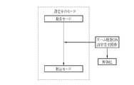
- the mode control unit 56 when the mode changeover switch 13a is used to switch to the length measurement mode, the setting conditions currently being set for the light source device 14, the endoscope 12, and the processor device 16 are predetermined. Prohibition When the setting condition is met, the setting change operation is performed when the setting condition setting change operation is performed by the user interface 19 during the first control and length measurement mode that prohibits switching to the length measurement mode. When the setting condition to be changed corresponds to the prohibited setting condition, the setting change operation of the setting condition is performed by the user interface 19 in the second control for invalidating the setting change operation or in the length measurement mode. In this case, if the setting condition to be changed by the setting change operation corresponds to the prohibition setting condition, at least one of the third controls for automatically switching from the length measurement mode to another mode is performed.
- the setting conditions for the light source device 14 include the illumination conditions of the illumination light used in the normal observation mode or the length measurement mode, the illumination conditions of the special light used in the special observation mode, or the illumination of the auxiliary light for measurement used in the length measurement mode. Conditions are included. Illumination conditions include, for example, the amount of illumination light.
- the setting conditions for the endoscope 12 include imaging conditions for imaging a subject. The imaging conditions include, for example, shutter speed and the like.
- the setting conditions for the processor device 16 include processing conditions such as image processing for the subject image. The processing conditions include, for example, color balance, brightness correction, and various enhancement processes.
- the position detection of the spot light SP is optimized, and the setting conditions (illumination light amount, shutter speed, color balance, brightness correction, various enhancement processing) that satisfy the visibility at the time of user's dimension measurement are set. It is preferable to do so.
- the prohibition setting conditions include the first prohibition setting condition that prevents the detection of the position of the measurement light irradiation area from the subject image in the length measurement mode, and the prevention of accurately displaying the measurement marker corresponding to the observation distance in the measurement image.
- the second prohibition setting condition is included.
- the first prohibition setting condition includes, for example, a special observation mode in which the measurement light image is not used for displaying the measurement image, brightness enhancement or red enhancement for the subject image, and the like. As described above, in the special observation mode, since the red image which is the measurement light image is not used for the display of the monitor 18, it is difficult to detect the measurement light irradiation area. In the length measurement mode, it is preferable to lower the brightness of the subject image and suppress the redness as compared with the normal observation mode or the special observation mode.
- the second prohibition setting condition includes, for example, the use (ON) of a zoom function such as an optical zoom function or a digital zoom function. This is because the measurement marker displayed in the measurement image is determined according to the position of the spot SP and not according to the magnification of the zoom function. Therefore, when the zoom function is ON, the measurement marker is set. This is because it is difficult to display according to the observation distance.
- a zoom function such as an optical zoom function or a digital zoom function.
- the mode control unit 56 switches to the length measurement mode as shown in FIG.
- the first control for maintaining the state of the special observation mode is performed by prohibiting the switching of.
- the mode control unit 56 displays a message on the monitor 18 notifying that the switching to the length measurement mode is prohibited (issues a warning sound). May be).
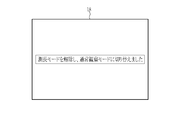
- the mode control unit 56 may perform control to cancel the special observation mode and switch to the length measurement mode as shown in FIG.
- the mode control unit 56 turns on the zoom function as shown in FIG.
- the second control is performed to invalidate the setting change operation.
- the mode control unit 56 displays a message on the monitor 18 notifying that the setting change operation for turning on the zoom function has been invalidated (as shown in FIG. 13). You may make a warning sound).
- the mode control unit 56 cancels the length measurement mode as shown in FIG. Then, as another mode, a third control for switching to the normal observation mode is performed.
- the mode control unit 56 notifies that the length measurement mode is canceled (the measurement marker is hidden) and the normal observation mode is switched to, as shown in FIG.
- the message to be displayed is displayed on the monitor 18 (a warning sound may be emitted).
- the setting change operation for turning on the zoom function is enabled, and the subject on the subject image is enlarged or reduced by the zoom function.
- the second signal processing unit 52 sets a first measurement marker as a measurement marker for measuring the size of the subject based on the irradiation position of the spot SP, and sets the first measurement marker on the monitor 18.
- the second signal processing unit 52 refers to the irradiation position by referring to the marker table 62 that stores the measurement marker image whose display mode differs depending on the irradiation position of the spot SP and the marker display position in association with the irradiation position of the spot. Set the measurement marker image corresponding to.
- the measurement marker image for example, has a different size or shape depending on the irradiation position of the spot SP and the marker display position.
- the display of the measurement marker image will be described later.
- the stored contents of the marker table 62 are maintained even when the power of the processor device 16 is turned off.
- the marker table 62 stores the measurement marker image and the irradiation position in association with each other, and stores the distance to the subject corresponding to the irradiation position (distance between the tip portion 12d of the endoscope 12 and the subject) and the measurement. It may be stored in association with the marker image.
- the display control unit 40 controls the display mode of the measurement marker to be different depending on the irradiation position of the spot SP and the marker display position. Do. Specifically, the display control unit 40 displays a measurement image on which a first measurement marker is superimposed, centered on the spot SP, on the monitor 18.
- the first measurement marker for example, a circular measurement marker is used. In this case, as shown in FIG. 16, when the observation distance is close to the near-end Px, the actual size is 5 mm (horizontal direction and vertical of the subject image) in accordance with the center of the spot SP1 formed on the tumor tm1 of the subject.
- the marker M1 indicating the direction) is displayed.
- the measurement marker is displayed on the monitor 18, the observation distance may also be displayed on the monitor 18.
- the marker display position of the marker M1 is located in the peripheral portion of the subject image affected by the distortion by the imaging optical system 21, the marker M1 has an elliptical shape according to the influence of the distortion and the like. Since the above marker M1 substantially coincides with the range of the tumor tm1, the tumor tm1 can be measured to be about 5 mm. Note that the spot may not be displayed on the subject image, and only the first measurement marker may be displayed.
- the actual size is 5 mm (horizontal and vertical directions of the subject image) in accordance with the center of the spot SP2 formed on the tumor tm2 of the subject.
- the indicator M2 is displayed. Since the marker display position of the marker M2 is located at the center of the subject image that is not easily affected by distortion by the imaging optical system 21, the marker M2 is circular without being affected by distortion or the like. ..
- a marker M3 indicating an actual size of 5 mm (horizontal direction and vertical direction of the subject image) is displayed so as to be aligned with the center of the spot SP3 formed on the tumor tm3 of the subject. Since the marker display position of the marker M3 is located in the peripheral portion of the subject image affected by the distortion caused by the imaging optical system 21, the marker M1 has an elliptical shape in accordance with the influence of the distortion or the like. As shown in FIGS. 16 to 18 above, the size of the first measurement marker corresponding to the same actual size of 5 mm becomes smaller as the observation distance becomes longer. Further, the shape of the first measurement marker differs depending on the marker display position according to the influence of the distortion caused by the imaging optical system 21.
- the center of the spot SP and the center of the marker are displayed so as to coincide with each other.
- the first measurement marker is located at a position away from the spot SP. May be displayed.
- the first measurement marker in a state in which the distortion aberration of the subject image is corrected and not deformed may be displayed in the corrected subject image. ..
- the first measurement marker corresponding to the actual size of the subject of 5 mm is displayed, but the actual size of the subject is an arbitrary value (for example, 2 mm) according to the observation target and the observation purpose. , 3 mm, 10 mm, etc.) may be set.
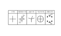
- the first measurement marker has a substantially circular shape, but as shown in FIG. 19, it may have a cross shape in which vertical lines and horizontal lines intersect. Further, a graduated cross shape in which a scale Mx is added to at least one of a cross-shaped vertical line and a horizontal line may be used.
- the first measurement marker a distorted cross shape in which at least one of a vertical line and a horizontal line is tilted may be used.
- the first measurement marker may be a circle in which a cross shape and a circle are combined and a cross shape.
- the first measurement marker may be a measurement point cloud type in which a plurality of measurement point EPs corresponding to the actual size from the spot are combined.
- the number of the first measurement markers may be one or a plurality, and the color of the first measurement markers may be changed according to the actual size.
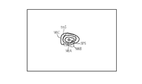
- the first measurement marker as shown in FIG. 20, three plurality of circular markers M4A, M4B, and M4C (the sizes are 2 mm, 5 mm, and 10 mm in diameter, respectively) having different sizes are used as tumors.
- the spot SP4 formed on the tm4 may be displayed on the subject image as a center. Since a plurality of these three concentric markers are displayed, the trouble of switching can be saved, and measurement is possible even when the subject has a non-linear shape.
- a combination of multiple conditions can be prepared in advance and selected from the combinations. It may be. Further, as shown in FIG.
- the three circular markers are concentric circles having the same center, but are not limited to concentric circles, and may be a plurality of circles based on the position of the spot SP4.
- all three concentric markers are displayed in the same color (black), but when displaying a plurality of concentric markers, they may be displayed as a plurality of colored concentric markers whose colors are changed by the markers.
- the marker M5A is represented by a dotted line representing red
- the marker M5B is represented by a solid line representing blue
- the marker M5C is represented by a alternate long and short dash line representing white.
- the first measurement marker in addition to a plurality of concentric markers, as shown in FIG. 22, a plurality of distorted concentric markers in which each concentric circle is distorted may be used.
- the distorted concentric markers M6A, M6B, and M6C are displayed on the subject image centering on the spot SP5 formed on the tumor tm5.
- the mode control unit 56 sets in advance the setting conditions currently being set for the light source device 14, the endoscope 12, or the processor device 16.
- the set prohibition setting condition is met, the operation of switching to the length measurement mode is invalidated, and the first control for prohibiting the switch to the length measurement mode is performed.
- the first control is performed, a message notifying "prohibition of switching to the length measurement mode" is displayed on the monitor 18. If the user wishes to use the length measurement mode, he / she operates the mode switching SW13a or the user interface 19 to change the setting condition to one that does not correspond to the prohibited setting condition. Then, the mode switching SW13a is operated again to switch to the length measurement mode. As a result, the mode is switched to the length measurement mode.
- the setting condition to be changed by the setting change operation corresponds to the prohibition setting condition.
- a message notifying "invalidation of the setting change operation" is displayed on the monitor 18.
- the user cancels the length measurement mode and enables the setting change operation.
- the user interface 19 or the like is operated to perform a third control for switching from the length measurement mode to another mode.
- the third control is performed, the setting change operation is enabled and the setting condition is changed.
- the monitor 18 displays a message notifying that "the length measurement mode has been switched to another mode". These notifications may use icons, indicators, etc. that indicate the length measurement mode state and observation conditions.
- the subject In the length measurement mode, the subject is constantly irradiated with the illumination light and the spot light (measurement light).
- the illumination light is constantly lit and constantly irradiates the subject with the spot.
- the light may intermittently irradiate the subject with spot light by repeating turning on and off (or dimming) every frame (or every few frames).
- the position of the spot light is detected and the display setting of the measurement marker is performed. Then, it is preferable to superimpose and display the measurement marker for which the display setting has been made on the image obtained in the frame that irradiates only the illumination light.
- the measurement light the light formed as a spot when the subject is irradiated is used, but other light may be used.
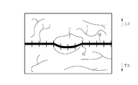
- a line-shaped measurement light formed as an intersecting line 80 on the subject may be used.
- the intersecting line 80 which is a line-shaped irradiation region, is formed on the subject.
- a second measurement marker including the intersection line 80 and the scale 82 as an index of the size of the subject is generated on the intersection line 80.
- the irradiation position detection unit 58 detects the position of the intersection line 80 (irradiation position of the measurement light).
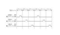
- the subject When line-shaped measurement light is used as the measurement light, the subject may be constantly irradiated with the illumination light and the line-shaped measurement light during the length measurement mode, and as shown in FIG. 26, the illumination light is While constantly irradiating the subject, the line-shaped measurement light intermittently illuminates the subject by repeating turning on and off (or dimming) every frame (or every few frames). You may. In this case, in the frame that lights the line-shaped measurement light, the position of the line-shaped measurement light is detected and the display of the measurement marker is set. Then, it is preferable to superimpose and display the measurement marker for which the display setting has been made on the image obtained in the frame that irradiates only the illumination light.
- the striped pattern light ZPL formed as the light of the striped pattern on the subject when the subject is irradiated may be used (for example, Japanese Patent Application Laid-Open No. 2016-1983304 (see).
- the striped pattern light ZPL is obtained by irradiating a liquid crystal shutter (not shown) with variable transmittance with a specific laser light, and a region (transmission region) through which the specific laser light is transmitted by the liquid crystal shutter and a specific laser light. Is formed from two different patterns of vertical stripes that do not pass through (non-transparent area) and repeat periodically in the horizontal direction.
- the cycle of the striped pattern light changes depending on the distance to the subject. Therefore, the cycle or phase of the striped pattern light is shifted by the liquid crystal shutter and irradiated multiple times.
- the three-dimensional shape of the subject is measured based on a plurality of images obtained by shifting the period or phase.
- the subject is alternately irradiated with the striped pattern light of phase X, the striped pattern light of phase Y, and the striped pattern light of phase Z.
- the striped pattern light of the phases X, Y, and Z is phase-shifted by 120 ° (2 ⁇ / 3) from the vertical striped pattern.
- the three-dimensional shape of the subject is measured using three types of images obtained based on each striped pattern light.
- the striped pattern light of phase X, the striped pattern light of phase Y, and the striped pattern light of phase Z are switched in units of one frame (or several frames). It is preferable to irradiate the subject. It is preferable that the illumination light always irradiates the subject.
- the measurement light LPL having a grid pattern formed as a grid pattern when the subject is irradiated may be used (for example, JP-A-2017-217215). See Gazette).
- the measurement light LPL of the grid pattern is not a perfect grid, but is slightly deformed from the grid such as wavy so as to improve the detection accuracy of the grid pattern.
- the grid pattern is provided with an S code indicating that the end points of the left and right horizontal lines are continuous.
- the grid pattern may be a pattern in which vertical lines and horizontal lines are regularly arranged, or a pattern in which a plurality of spots are arranged in a vertical and horizontal grid pattern.
- the subject may be constantly irradiated with the illumination light and the grid pattern measurement light LPL during the length measurement mode, and as shown in FIG. While the illumination light constantly illuminates the subject, the grid pattern measurement light LPL repeats turning on and off (or dimming) every frame (or every few frames) to measure the grid pattern.
- the subject may be irradiated with the LPL intermittently. In this case, in the frame that lights the measurement light LPL of the grid pattern, the three-dimensional shape is measured based on the measurement light LPL of the grid pattern. Then, it is preferable to superimpose and display the measurement result of the three-dimensional shape on the image obtained in the frame that irradiates only the illumination light.
- a three-dimensional plane light TPL represented by a mesh line on the subject image may be used (see, for example, Japanese Patent Publication No. 2017-508529).
- the tip portion 12d is moved so that the three-dimensional plane light TPL matches the measurement target.
- the distance of the intersection curve CC between the three-dimensional parallel light TPL and the subject is calculated by a process based on a manual operation such as a user interface or an automatic process.
- the subject When the three-dimensional plane light TPL is used as the measurement light, the subject may be constantly irradiated with the illumination light and the three-dimensional plane light TPL during the length measurement mode, and as shown in FIG. 32, the illumination light is While constantly irradiating the subject, the three-dimensional plane light TPL intermittently irradiates the subject with the three-dimensional plane light TPL by repeating turning on and off (or dimming) every frame (or every few frames). You may.
- the hardware structure of the processing unit that executes various processes is various processors as shown below.
- the circuit configuration is changed after manufacturing the CPU (Central Processing Unit), FPGA (Field Programmable Gate Array), etc., which are general-purpose processors that execute software (programs) and function as various processing units. It includes a programmable logic device (PLD), which is a possible processor, a dedicated electric circuit, which is a processor having a circuit configuration specially designed for executing various processes, and the like.
- PLD programmable logic device
- One processing unit may be composed of one of these various processors, or may be composed of a combination of two or more processors of the same type or different types (for example, a plurality of FPGAs or a combination of a CPU and an FPGA). May be done. Further, a plurality of processing units may be configured by one processor. As an example of configuring a plurality of processing units with one processor, first, as represented by a computer such as a client or a server, one processor is configured by a combination of one or more CPUs and software. There is a form in which this processor functions as a plurality of processing units.
- SoC System On Chip
- a processor that realizes the functions of the entire system including a plurality of processing units with one IC (Integrated Circuit) chip is used.
- the various processing units are configured by using one or more of the above-mentioned various processors as a hardware-like structure.
- the hardware structure of these various processors is, more specifically, an electric circuit in the form of a combination of circuit elements such as semiconductor elements.
- the hardware structure of the storage unit is a storage device such as an HDD (hard disk drive) or SSD (solid state drive).
- the measurement light and the irradiation of the measurement light are preferably as follows.
- the measurement light is preferably spot light.
- the measurement light is preferably a line-shaped measurement light.
- the measurement light is preferably a measurement light having a grid pattern.
- the measurement light is preferably three-dimensional plane light. It is preferable to intermittently irradiate the subject with the measurement light.
- the measurement light is preferably striped pattern light. It is preferable to switch a plurality of striped pattern lights having different phases or periods to irradiate the subject.
Landscapes
- Health & Medical Sciences (AREA)
- Life Sciences & Earth Sciences (AREA)
- Physics & Mathematics (AREA)
- Surgery (AREA)
- Engineering & Computer Science (AREA)
- Optics & Photonics (AREA)
- Medical Informatics (AREA)
- General Health & Medical Sciences (AREA)
- Pathology (AREA)
- Veterinary Medicine (AREA)
- Biomedical Technology (AREA)
- Heart & Thoracic Surgery (AREA)
- Biophysics (AREA)
- Molecular Biology (AREA)
- Animal Behavior & Ethology (AREA)
- Public Health (AREA)
- Radiology & Medical Imaging (AREA)
- Nuclear Medicine, Radiotherapy & Molecular Imaging (AREA)
- Astronomy & Astrophysics (AREA)
- General Physics & Mathematics (AREA)
- Signal Processing (AREA)
- Dentistry (AREA)
- Oral & Maxillofacial Surgery (AREA)
- Endoscopes (AREA)
- Instruments For Viewing The Inside Of Hollow Bodies (AREA)
Priority Applications (3)
| Application Number | Priority Date | Filing Date | Title |
|---|---|---|---|
| CN202080056811.7A CN114207499B (zh) | 2019-08-13 | 2020-08-04 | 内窥镜系统及其工作方法 |
| JP2021539221A JP7116264B2 (ja) | 2019-08-13 | 2020-08-04 | 内視鏡システム及びその作動方法 |
| EP20851701.1A EP4016162B1 (en) | 2019-08-13 | 2020-08-04 | Endoscope system and method for operating same |
Applications Claiming Priority (4)
| Application Number | Priority Date | Filing Date | Title |
|---|---|---|---|
| JP2019-148607 | 2019-08-13 | ||
| JP2019148607 | 2019-08-13 | ||
| JP2020-051379 | 2020-03-23 | ||
| JP2020051379 | 2020-03-23 |
Publications (1)
| Publication Number | Publication Date |
|---|---|
| WO2021029277A1 true WO2021029277A1 (ja) | 2021-02-18 |
Family
ID=74571061
Family Applications (1)
| Application Number | Title | Priority Date | Filing Date |
|---|---|---|---|
| PCT/JP2020/029827 Ceased WO2021029277A1 (ja) | 2019-08-13 | 2020-08-04 | 内視鏡システム及びその作動方法 |
Country Status (4)
| Country | Link |
|---|---|
| EP (1) | EP4016162B1 (https=) |
| JP (1) | JP7116264B2 (https=) |
| CN (1) | CN114207499B (https=) |
| WO (1) | WO2021029277A1 (https=) |
Cited By (1)
| Publication number | Priority date | Publication date | Assignee | Title |
|---|---|---|---|---|
| CN115399711A (zh) * | 2021-05-26 | 2022-11-29 | 富士胶片株式会社 | 内窥镜业务辅助装置及内窥镜业务辅助系统以及内窥镜业务辅助装置的工作方法 |
Families Citing this family (1)
| Publication number | Priority date | Publication date | Assignee | Title |
|---|---|---|---|---|
| CN115143929A (zh) * | 2022-03-28 | 2022-10-04 | 南京大学 | 一种基于光纤束的内窥测距仪 |
Citations (9)
| Publication number | Priority date | Publication date | Assignee | Title |
|---|---|---|---|---|
| JP2008125996A (ja) * | 2006-11-24 | 2008-06-05 | Pentax Corp | 内視鏡被写体距離測定システム |
| JP2016198304A (ja) | 2015-04-10 | 2016-12-01 | オリンパス株式会社 | 内視鏡システム |
| JP2017508529A (ja) | 2014-03-02 | 2017-03-30 | ブイ.ティー.エム.(バーチャル テープ メジャー)テクノロジーズ リミテッド | 内視鏡測定システム及び方法 |
| JP2017217215A (ja) | 2016-06-07 | 2017-12-14 | 公立大学法人広島市立大学 | 3次元形状計測装置及び3次元形状計測方法 |
| WO2018051680A1 (ja) | 2016-09-15 | 2018-03-22 | 富士フイルム株式会社 | 内視鏡システム |
| WO2018055933A1 (ja) * | 2016-09-20 | 2018-03-29 | 富士フイルム株式会社 | 計測支援装置、内視鏡システム、内視鏡システムのプロセッサ、及び計測支援方法 |
| WO2018180250A1 (ja) * | 2017-03-28 | 2018-10-04 | 富士フイルム株式会社 | 計測支援装置、内視鏡システム、及びプロセッサ |
| WO2019017018A1 (ja) * | 2017-07-18 | 2019-01-24 | 富士フイルム株式会社 | 内視鏡装置及び計測支援方法 |
| JP2020014808A (ja) * | 2018-07-27 | 2020-01-30 | 富士フイルム株式会社 | 内視鏡装置及びその作動方法並び内視鏡装置用プログラム |
Family Cites Families (6)
| Publication number | Priority date | Publication date | Assignee | Title |
|---|---|---|---|---|
| JP3441449B2 (ja) * | 1991-03-11 | 2003-09-02 | オリンパス光学工業株式会社 | 内視鏡装置 |
| JP5371366B2 (ja) * | 2008-10-22 | 2013-12-18 | 富士フイルム株式会社 | 内視鏡装置および内視鏡装置の作動方法 |
| EP2737843A4 (en) * | 2012-03-29 | 2015-05-06 | Olympus Medical Systems Corp | ENDOSCOPE SYSTEM |
| JP6016226B2 (ja) * | 2012-04-04 | 2016-10-26 | シャープ株式会社 | 測長装置、測長方法、プログラム |
| JP2016032485A (ja) * | 2012-12-27 | 2016-03-10 | 国立大学法人 東京医科歯科大学 | 内視鏡下手術支援システム及び画像制御方法 |
| WO2018083879A1 (ja) * | 2016-11-01 | 2018-05-11 | オリンパス株式会社 | 生体観察システム |
-
2020
- 2020-08-04 JP JP2021539221A patent/JP7116264B2/ja active Active
- 2020-08-04 CN CN202080056811.7A patent/CN114207499B/zh active Active
- 2020-08-04 EP EP20851701.1A patent/EP4016162B1/en active Active
- 2020-08-04 WO PCT/JP2020/029827 patent/WO2021029277A1/ja not_active Ceased
Patent Citations (9)
| Publication number | Priority date | Publication date | Assignee | Title |
|---|---|---|---|---|
| JP2008125996A (ja) * | 2006-11-24 | 2008-06-05 | Pentax Corp | 内視鏡被写体距離測定システム |
| JP2017508529A (ja) | 2014-03-02 | 2017-03-30 | ブイ.ティー.エム.(バーチャル テープ メジャー)テクノロジーズ リミテッド | 内視鏡測定システム及び方法 |
| JP2016198304A (ja) | 2015-04-10 | 2016-12-01 | オリンパス株式会社 | 内視鏡システム |
| JP2017217215A (ja) | 2016-06-07 | 2017-12-14 | 公立大学法人広島市立大学 | 3次元形状計測装置及び3次元形状計測方法 |
| WO2018051680A1 (ja) | 2016-09-15 | 2018-03-22 | 富士フイルム株式会社 | 内視鏡システム |
| WO2018055933A1 (ja) * | 2016-09-20 | 2018-03-29 | 富士フイルム株式会社 | 計測支援装置、内視鏡システム、内視鏡システムのプロセッサ、及び計測支援方法 |
| WO2018180250A1 (ja) * | 2017-03-28 | 2018-10-04 | 富士フイルム株式会社 | 計測支援装置、内視鏡システム、及びプロセッサ |
| WO2019017018A1 (ja) * | 2017-07-18 | 2019-01-24 | 富士フイルム株式会社 | 内視鏡装置及び計測支援方法 |
| JP2020014808A (ja) * | 2018-07-27 | 2020-01-30 | 富士フイルム株式会社 | 内視鏡装置及びその作動方法並び内視鏡装置用プログラム |
Non-Patent Citations (1)
| Title |
|---|
| See also references of EP4016162A4 |
Cited By (3)
| Publication number | Priority date | Publication date | Assignee | Title |
|---|---|---|---|---|
| CN115399711A (zh) * | 2021-05-26 | 2022-11-29 | 富士胶片株式会社 | 内窥镜业务辅助装置及内窥镜业务辅助系统以及内窥镜业务辅助装置的工作方法 |
| EP4094668A1 (en) * | 2021-05-26 | 2022-11-30 | FUJIFILM Corporation | Endoscopy service support device, endoscopy service support system, and method of operating endoscopy service support device |
| US12029386B2 (en) | 2021-05-26 | 2024-07-09 | Fujifilm Corporation | Endoscopy service support device, endoscopy service support system, and method of operating endoscopy service support device |
Also Published As
| Publication number | Publication date |
|---|---|
| JPWO2021029277A1 (https=) | 2021-02-18 |
| CN114207499A (zh) | 2022-03-18 |
| EP4016162B1 (en) | 2025-06-25 |
| CN114207499B (zh) | 2024-11-22 |
| EP4016162A1 (en) | 2022-06-22 |
| JP7116264B2 (ja) | 2022-08-09 |
| EP4016162A4 (en) | 2022-10-12 |
Similar Documents
| Publication | Publication Date | Title |
|---|---|---|
| JP7569384B2 (ja) | 内視鏡システム及びその作動方法 | |
| JP7099971B2 (ja) | 内視鏡装置、キャリブレーション装置、及びキャリブレーション方法 | |
| EP3586719B1 (en) | Endoscope apparatus | |
| JP7167352B2 (ja) | 内視鏡システム及びその作動方法 | |
| WO2022224859A1 (ja) | 内視鏡システム及びその作動方法 | |
| JP7116264B2 (ja) | 内視鏡システム及びその作動方法 | |
| WO2021132153A1 (ja) | 内視鏡及び内視鏡システム | |
| US12029386B2 (en) | Endoscopy service support device, endoscopy service support system, and method of operating endoscopy service support device | |
| JP7069062B2 (ja) | 内視鏡装置 | |
| JP7447249B2 (ja) | テストチャート、検査システム、及び検査方法 | |
| JP7029359B2 (ja) | 内視鏡装置及びその作動方法並び内視鏡装置用プログラム | |
| JPWO2021029277A5 (https=) | ||
| US12133626B2 (en) | Endoscope system and endoscope system operation method | |
| JP2020014808A (ja) | 内視鏡装置及びその作動方法並び内視鏡装置用プログラム | |
| JP7214840B2 (ja) | 内視鏡、内視鏡装置 | |
| JP2020005745A (ja) | 内視鏡装置 | |
| WO2022049806A1 (ja) | キャリブレーション装置及び方法 | |
| CN115530972A (zh) | 手术导航装置及系统 |
Legal Events
| Date | Code | Title | Description |
|---|---|---|---|
| 121 | Ep: the epo has been informed by wipo that ep was designated in this application |
Ref document number: 20851701 Country of ref document: EP Kind code of ref document: A1 |
|
| ENP | Entry into the national phase |
Ref document number: 2021539221 Country of ref document: JP Kind code of ref document: A |
|
| NENP | Non-entry into the national phase |
Ref country code: DE |
|
| ENP | Entry into the national phase |
Ref document number: 2020851701 Country of ref document: EP Effective date: 20220314 |
|
| WWG | Wipo information: grant in national office |
Ref document number: 2020851701 Country of ref document: EP |