WO2021029199A1 - コネクタ - Google Patents
コネクタ Download PDFInfo
- Publication number
- WO2021029199A1 WO2021029199A1 PCT/JP2020/028468 JP2020028468W WO2021029199A1 WO 2021029199 A1 WO2021029199 A1 WO 2021029199A1 JP 2020028468 W JP2020028468 W JP 2020028468W WO 2021029199 A1 WO2021029199 A1 WO 2021029199A1
- Authority
- WO
- WIPO (PCT)
- Prior art keywords
- outer conductor
- male
- female
- connector
- conductor
- Prior art date
- Legal status (The legal status is an assumption and is not a legal conclusion. Google has not performed a legal analysis and makes no representation as to the accuracy of the status listed.)
- Ceased
Links
Images


Classifications
-
- H—ELECTRICITY
- H01—ELECTRIC ELEMENTS
- H01R—ELECTRICALLY-CONDUCTIVE CONNECTIONS; STRUCTURAL ASSOCIATIONS OF A PLURALITY OF MUTUALLY-INSULATED ELECTRICAL CONNECTING ELEMENTS; COUPLING DEVICES; CURRENT COLLECTORS
- H01R13/00—Details of coupling devices of the kinds covered by groups H01R12/70 or H01R24/00 - H01R33/00
- H01R13/648—Protective earth or shield arrangements on coupling devices, e.g. anti-static shielding
- H01R13/658—High frequency shielding arrangements, e.g. against EMI [Electro-Magnetic Interference] or EMP [Electro-Magnetic Pulse]
- H01R13/6591—Specific features or arrangements of connection of shield to conductive members
- H01R13/6592—Specific features or arrangements of connection of shield to conductive members the conductive member being a shielded cable
- H01R13/6593—Specific features or arrangements of connection of shield to conductive members the conductive member being a shielded cable the shield being composed of different pieces
-
- H—ELECTRICITY
- H01—ELECTRIC ELEMENTS
- H01R—ELECTRICALLY-CONDUCTIVE CONNECTIONS; STRUCTURAL ASSOCIATIONS OF A PLURALITY OF MUTUALLY-INSULATED ELECTRICAL CONNECTING ELEMENTS; COUPLING DEVICES; CURRENT COLLECTORS
- H01R13/00—Details of coupling devices of the kinds covered by groups H01R12/70 or H01R24/00 - H01R33/00
- H01R13/648—Protective earth or shield arrangements on coupling devices, e.g. anti-static shielding
- H01R13/658—High frequency shielding arrangements, e.g. against EMI [Electro-Magnetic Interference] or EMP [Electro-Magnetic Pulse]
- H01R13/6581—Shield structure
-
- H—ELECTRICITY
- H01—ELECTRIC ELEMENTS
- H01R—ELECTRICALLY-CONDUCTIVE CONNECTIONS; STRUCTURAL ASSOCIATIONS OF A PLURALITY OF MUTUALLY-INSULATED ELECTRICAL CONNECTING ELEMENTS; COUPLING DEVICES; CURRENT COLLECTORS
- H01R13/00—Details of coupling devices of the kinds covered by groups H01R12/70 or H01R24/00 - H01R33/00
- H01R13/02—Contact members
- H01R13/04—Pins or blades for co-operation with sockets
- H01R13/05—Resilient pins or blades
-
- H—ELECTRICITY
- H01—ELECTRIC ELEMENTS
- H01R—ELECTRICALLY-CONDUCTIVE CONNECTIONS; STRUCTURAL ASSOCIATIONS OF A PLURALITY OF MUTUALLY-INSULATED ELECTRICAL CONNECTING ELEMENTS; COUPLING DEVICES; CURRENT COLLECTORS
- H01R13/00—Details of coupling devices of the kinds covered by groups H01R12/70 or H01R24/00 - H01R33/00
- H01R13/62—Means for facilitating engagement or disengagement of coupling parts or for holding them in engagement
- H01R13/629—Additional means for facilitating engagement or disengagement of coupling parts, e.g. aligning or guiding means, levers, gas pressure electrical locking indicators, manufacturing tolerances
-
- H—ELECTRICITY
- H01—ELECTRIC ELEMENTS
- H01R—ELECTRICALLY-CONDUCTIVE CONNECTIONS; STRUCTURAL ASSOCIATIONS OF A PLURALITY OF MUTUALLY-INSULATED ELECTRICAL CONNECTING ELEMENTS; COUPLING DEVICES; CURRENT COLLECTORS
- H01R13/00—Details of coupling devices of the kinds covered by groups H01R12/70 or H01R24/00 - H01R33/00
- H01R13/64—Means for preventing incorrect coupling
-
- H—ELECTRICITY
- H01—ELECTRIC ELEMENTS
- H01R—ELECTRICALLY-CONDUCTIVE CONNECTIONS; STRUCTURAL ASSOCIATIONS OF A PLURALITY OF MUTUALLY-INSULATED ELECTRICAL CONNECTING ELEMENTS; COUPLING DEVICES; CURRENT COLLECTORS
- H01R13/00—Details of coupling devices of the kinds covered by groups H01R12/70 or H01R24/00 - H01R33/00
- H01R13/648—Protective earth or shield arrangements on coupling devices, e.g. anti-static shielding
- H01R13/658—High frequency shielding arrangements, e.g. against EMI [Electro-Magnetic Interference] or EMP [Electro-Magnetic Pulse]
- H01R13/6581—Shield structure
- H01R13/6582—Shield structure with resilient means for engaging mating connector
- H01R13/6583—Shield structure with resilient means for engaging mating connector with separate conductive resilient members between mating shield members
-
- H—ELECTRICITY
- H01—ELECTRIC ELEMENTS
- H01R—ELECTRICALLY-CONDUCTIVE CONNECTIONS; STRUCTURAL ASSOCIATIONS OF A PLURALITY OF MUTUALLY-INSULATED ELECTRICAL CONNECTING ELEMENTS; COUPLING DEVICES; CURRENT COLLECTORS
- H01R9/00—Structural associations of a plurality of mutually-insulated electrical connecting elements, e.g. terminal strips or terminal blocks; Terminals or binding posts mounted upon a base or in a case; Bases therefor
- H01R9/03—Connectors arranged to contact a plurality of the conductors of a multiconductor cable, e.g. tapping connections
- H01R9/05—Connectors arranged to contact a plurality of the conductors of a multiconductor cable, e.g. tapping connections for coaxial cables
-
- H—ELECTRICITY
- H01—ELECTRIC ELEMENTS
- H01R—ELECTRICALLY-CONDUCTIVE CONNECTIONS; STRUCTURAL ASSOCIATIONS OF A PLURALITY OF MUTUALLY-INSULATED ELECTRICAL CONNECTING ELEMENTS; COUPLING DEVICES; CURRENT COLLECTORS
- H01R13/00—Details of coupling devices of the kinds covered by groups H01R12/70 or H01R24/00 - H01R33/00
- H01R13/40—Securing contact members in or to a base or case; Insulating of contact members
- H01R13/42—Securing in a demountable manner
- H01R13/428—Securing in a demountable manner by resilient locking means on the contact members; by locking means on resilient contact members
-
- H—ELECTRICITY
- H01—ELECTRIC ELEMENTS
- H01R—ELECTRICALLY-CONDUCTIVE CONNECTIONS; STRUCTURAL ASSOCIATIONS OF A PLURALITY OF MUTUALLY-INSULATED ELECTRICAL CONNECTING ELEMENTS; COUPLING DEVICES; CURRENT COLLECTORS
- H01R13/00—Details of coupling devices of the kinds covered by groups H01R12/70 or H01R24/00 - H01R33/00
- H01R13/46—Bases; Cases
- H01R13/502—Bases; Cases composed of different pieces
- H01R13/506—Bases; Cases composed of different pieces assembled by snap action of the parts
-
- H—ELECTRICITY
- H01—ELECTRIC ELEMENTS
- H01R—ELECTRICALLY-CONDUCTIVE CONNECTIONS; STRUCTURAL ASSOCIATIONS OF A PLURALITY OF MUTUALLY-INSULATED ELECTRICAL CONNECTING ELEMENTS; COUPLING DEVICES; CURRENT COLLECTORS
- H01R13/00—Details of coupling devices of the kinds covered by groups H01R12/70 or H01R24/00 - H01R33/00
- H01R13/648—Protective earth or shield arrangements on coupling devices, e.g. anti-static shielding
- H01R13/658—High frequency shielding arrangements, e.g. against EMI [Electro-Magnetic Interference] or EMP [Electro-Magnetic Pulse]
- H01R13/6591—Specific features or arrangements of connection of shield to conductive members
- H01R13/6592—Specific features or arrangements of connection of shield to conductive members the conductive member being a shielded cable
-
- H—ELECTRICITY
- H01—ELECTRIC ELEMENTS
- H01R—ELECTRICALLY-CONDUCTIVE CONNECTIONS; STRUCTURAL ASSOCIATIONS OF A PLURALITY OF MUTUALLY-INSULATED ELECTRICAL CONNECTING ELEMENTS; COUPLING DEVICES; CURRENT COLLECTORS
- H01R9/00—Structural associations of a plurality of mutually-insulated electrical connecting elements, e.g. terminal strips or terminal blocks; Terminals or binding posts mounted upon a base or in a case; Bases therefor
- H01R9/03—Connectors arranged to contact a plurality of the conductors of a multiconductor cable, e.g. tapping connections
- H01R9/05—Connectors arranged to contact a plurality of the conductors of a multiconductor cable, e.g. tapping connections for coaxial cables
- H01R9/0512—Connections to an additional grounding conductor
-
- H—ELECTRICITY
- H01—ELECTRIC ELEMENTS
- H01R—ELECTRICALLY-CONDUCTIVE CONNECTIONS; STRUCTURAL ASSOCIATIONS OF A PLURALITY OF MUTUALLY-INSULATED ELECTRICAL CONNECTING ELEMENTS; COUPLING DEVICES; CURRENT COLLECTORS
- H01R9/00—Structural associations of a plurality of mutually-insulated electrical connecting elements, e.g. terminal strips or terminal blocks; Terminals or binding posts mounted upon a base or in a case; Bases therefor
- H01R9/03—Connectors arranged to contact a plurality of the conductors of a multiconductor cable, e.g. tapping connections
- H01R9/05—Connectors arranged to contact a plurality of the conductors of a multiconductor cable, e.g. tapping connections for coaxial cables
- H01R9/0518—Connection to outer conductor by crimping or by crimping ferrule
Definitions
- This disclosure relates to connectors.
- a shield connector described in Japanese Patent Application Laid-Open No. 2018-6183 is known as a shield connector connected to a terminal of a cable through which a communication signal is transmitted.
- This shield connector is a male connector, and has a male inner conductor and an outer conductor surrounding the male inner conductor via a dielectric material. Further, the male connector can be fitted with the female connector.
- the female connector has a female inner conductor and a female outer conductor that surrounds the female inner conductor via a female dielectric. When the male connector and the female connector are fitted, the outer conductor is fitted to the outside of the female side outer conductor, and the outer conductor and the female side outer conductor are connected.
- the outer conductor is configured by assembling an upper outer conductor and a lower outer conductor. For this reason, when it takes time to align the upper outer conductor and the lower outer conductor, the efficiency of the work of assembling the upper outer conductor and the lower outer conductor is lowered, and the efficiency of the connector assembling work is lowered as a whole. There is a risk.
- This specification discloses a technique for improving the efficiency of connector assembly work.
- the connector of the present disclosure is a connector connected to the end of a cable whose outer circumference is covered with a shield body, and has a first outer conductor and a second outer conductor assembled to the first outer conductor.
- the first outer conductor and the second outer conductor form a dielectric in which the inner conductor connected to the electric wire is housed.
- One of the first outer conductor and the second outer conductor is formed with a positioning convex portion that protrudes toward the other, and the other of the first outer conductor and the second outer conductor. Is formed with a positioning recess that engages with the positioning protrusion.
- the efficiency of the connector assembly work can be improved.
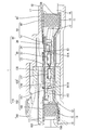
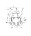
- FIG. 1 is a cross-sectional view showing a connector device according to the first embodiment.
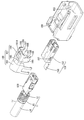
- FIG. 2 is an exploded perspective view showing a female connector.
- FIG. 3 is a plan view showing the female first outer conductor.
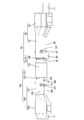
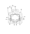
- FIG. 4 is a perspective view in which the male housing and the female housing are omitted in a state where the male connector and the female connector are fitted.
- FIG. 5 is a perspective view seen from an angle different from that of FIG. 4, and is a perspective view in which the male housing and the female housing are omitted in a state where the male connector and the female connector are fitted.
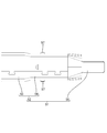
- FIG. 6 is a side view showing a state in which the male connector and the female connector are fitted.
- FIG. 7 is a cross-sectional view showing a state in which the female guide groove, the female stabilizer, and the female folded portion are engaged with each other.
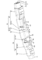
- FIG. 8 is an exploded perspective view showing a male connector.
- FIG. 9 is a plan view showing the male first outer conductor.
- FIG. 10 is a cross-sectional view showing a state in which the male guide groove, the male stabilizer, and the male folded portion are engaged with each other.
- the present disclosure is a connector in which the outer circumference of an electric wire is connected to the end of a cable covered with a shield body, and the first outer conductor and the second outer conductor assembled to the first outer conductor are described.
- the first outer conductor and the second outer conductor are dielectrics in which the inner conductor connected to the electric wire is housed.
- a positioning convex portion is formed on one of the first outer conductor and the second outer conductor so as to project toward the other, and of the first outer conductor and the second outer conductor.
- a positioning recess that engages with the positioning protrusion is formed.
- the efficiency of the assembling work of the first outer conductor and the second outer conductor can be improved by engaging the positioning convex portion and the positioning concave portion.
- the efficiency of the connector assembly work can be improved.
- the second outer conductor is assembled to the outside of the first outer conductor, and the positioning convex portion is formed on the first outer conductor so as to project outward, and the second outer conductor is formed. It is preferable that the positioning recess is formed in the conductor, and the positioning recess is a slit extending along the assembling direction in which the first outer conductor and the second outer conductor are assembled.
- the operator sets the second outer conductor as the first outer conductor by using the positioning convex portion formed so as to project outward as a mark. Can be assembled to a conductor.
- the efficiency of the assembling work of the first outer conductor and the second outer conductor can be improved, so that the efficiency of the connector assembling work can be further improved.
- the second outer conductor has a crimping piece to be crimped to the outer periphery of the first outer conductor, and the side edge of the crimping piece forms the mouth edge of the slit.
- the crimping piece can be reliably positioned, so that the assembly accuracy of the first outer conductor and the second outer conductor can be improved.
- the first outer conductor and the second outer conductor are housed in the housing in an assembled state, and the second outer conductor has a stabilizer that engages with the housing. It is preferable that the side edge of the stabilizer forms the mouth edge of the slit.
- the stabilizer can be reliably positioned, so that the accuracy of assembling the housing with the first outer conductor and the second outer conductor can be improved.
- the stabilizer has a folded portion in which the tip end portion of the stabilizer is folded back, and the folded portion is inserted into a guide groove formed in the housing.
- FIGS. 1 to 10 The first embodiment in the present disclosure will be described with reference to FIGS. 1 to 10.
- This embodiment is mounted on, for example, a vehicle (not shown) such as an automobile, and is, for example, between an in-vehicle electrical component (car navigation system, monitor, etc.) and an external device (camera, etc.) in the vehicle, or an in-vehicle electrical component.
- An example is a connector device 1 for communication arranged in a wired communication path between the two.
- the connector device 1 includes a female connector 110 (an example of a connector) and a male connector 10 (an example of a connector) that are connected to a cable 11 and are fitted to each other.
- a female connector 110 an example of a connector
- a male connector 10 an example of a connector
- the cable 11 covers two electric wires 12 (an example of an electric wire), a shield body 15 composed of a braided body that collectively covers the outer circumference of the electric wires 12, and a further outer circumference of the shield body 15. It is configured to include a sheath portion 16 made of an insulating coating.
- the braided body is made by weaving a plurality of fibrous conductors.
- the conductor constituting the braided body may be a fine metal wire or a synthetic resin fiber having a metal bonded to the surface, and any conductor can be selected. A plurality of fine metal wires are woven into the shield body 15 according to the present embodiment.
- the sheath portion 16 and the shield body 15 are peeled off, and the two electric wires 12 exposed from the terminals of the sheath portion 16 and the shield body 15 are exposed. .. Behind the exposed electric wire 12 in the cable 11, the shield body 15 exposed from the terminal of the sheath portion 16 is folded back on the end portion of the sheath portion 16.
- a metal sleeve 17 is arranged inside the shield body 15 folded over the end of the sheath portion 16.
- the sleeve 17 is formed in a cylindrical shape.
- the female connector 110 includes a plurality of female inner conductors 120 (an example of an inner conductor) connected to two exposed electric wires 12 at the front end of the cable 11, and a plurality of females.
- a female dielectric 130 for accommodating the inner conductor 120, a female outer conductor 150 connected to the shield body 15 of the cable 11 while covering the female dielectric 130, and a female housing 180 for accommodating the female outer conductor 150 are provided. It is composed of.
- the female inner conductor 120 is formed by processing a conductive metal plate material. As shown in FIG. 1, the female inner conductor 120 includes a square tubular terminal connecting portion 122 and an electric wire connecting portion 124 connected to the rear of the terminal connecting portion 122.
- the terminal connection portion 122 is electrically connected to the male inner conductor 20 (an example of the inner conductor) of the male connector 10 described later.
- the electric wire connecting portion 124 is crimped to the front end portion of the electric wire 12 and is electrically connected to the electric wire 12.
- the female dielectric 130 is formed of an insulating synthetic resin in a rectangular parallelepiped shape that is long in the front-rear direction. Inside the female dielectric 130, two female inner conductors 120 connected to the electric wire 12 are housed side by side in the left-right direction.
- the female outer conductor 150 includes a female first outer conductor 151 (an example of the first outer conductor) and a female second outer conductor 160 (of the second outer conductor) assembled to the female first outer conductor. An example) and.
- the female first outer conductor 151 and the female second outer conductor 160 are formed by pressing a conductive metal plate material into a predetermined shape.
- the female second outer conductor 160 is assembled from above with respect to the female first outer conductor 151.
- the female first outer conductor 151 has a tubular connecting portion 152 that can be fitted with the male outer conductor 50 of the male connector 10 described later, and a female shield connected to the shield body 15 of the cable 11. It is provided with a connecting portion 156.
- the tubular connection portion 152 is formed in a square tubular shape that is long in the front-rear direction.
- the female dielectric 130 is accommodated in the tubular connection portion 152 from the rear to the inside.
- the female inner conductor 120 is housed in a state of being electrically insulated from the tubular connection 152 by the female dielectric 130, as shown in FIG. It is supposed to be done.
- female positioning convex portions 157 (an example of the positioning convex portions) projecting outward are formed on the left and right side walls of the tubular connecting portion 152.
- the female positioning convex portion 157 has a substantially cylindrical shape.
- the female shield connecting portion 156 is formed in a plate shape extending rearward from the lower lower end portion of the tubular connecting portion 152.
- the female shield connection portion 156 is arranged below the shield body 15 in the cable 11 as shown in FIG.
- the female second outer conductor 160 is formed by processing a conductive metal plate material by a press or the like. As shown in FIG. 2, the female second outer conductor 160 includes a covering portion 161 that is assembled to the outer periphery of the tubular connecting portion 152, and a female barrel 163 that is crimped to the outer periphery of the shield body 15.
- the covering portion 161 is wound around the outer peripheral surface of the outer peripheral surface of the tubular connecting portion 152.
- the covering portion 161 has an upper wall 164 and a side wall 165 extending downward from the left and right side edges of the upper wall 164.
- a female stabilizer 166 (an example of a stabilizer), a female slit 167 (an example of a positioning recess), and a female crimping piece 168 (an example of a crimping piece) are formed on the side wall 165 in order from the front to the rear. ..
- a female stabilizer 166 extending downward is formed at a position closer to the front end of the lower end of the side wall 165.
- the female stabilizer 166 is formed in a plate shape extending downward and elongated.
- the lower end of the female stabilizer 166 is a female folded portion 169 (an example of the folded portion) that is folded upward so as to overlap the outer surface of the female stabilizer 166.
- a female slit 167 extending upward from the lower end of the side wall 165 is formed behind the female stabilizer 166.
- the posterior edge of the female stabilizer 166 constitutes the anterior rim of the female slit 167.
- a female crimping piece 168 extending from the lower end of the side wall 165 is formed. As shown in FIG. 2, in the state before the female second outer conductor 160 is assembled to the female first outer conductor 151, the female crimping piece 168 extends downward from the lower end portion of the side wall.
- the female second outer conductor 160 and the female first outer conductor 151 are integrally assembled by crimping the female crimping piece 168 so as to wrap around the tubular connecting portion 152. It has become like.
- the front edge of the female crimp piece 168 constitutes the posterior rim of the female slit 167.
- the width dimension of the female slit 167 in the front-rear direction is the same as or slightly larger than the outer diameter dimension of the female positioning convex portion 157. As a result, the female positioning convex portion 157 is accommodated in the female slit 167.
- the female positioning protrusion 157 is inserted into the female slit 167, so that the female second outer conductor 160 and the female first outer conductor 160 are assembled. It is designed to be aligned with. Further, when the female crimping piece 168 is crimped to the tubular connecting portion 152, both or one of the female first outer conductor and the female second outer conductor may extend in the front-rear direction.
- the female positioning convex portion 157 and the rim of the female slit 167 come into contact with each other in the front-rear direction, so that the displacement of the female second outer conductor 160 and the female first outer conductor 151 in the front-rear direction is suppressed. It has become so.
- the female barrel 163 is electrically connected and fixed to the shield body 15 by crimping to the outer circumference of the shield body 15 folded back in the cable 11. That is, the female barrel 163 is crimp-fixed together with the female shield connecting portion 156 so as to be wound around the shield body 15 of the cable 11.
- the female housing 180 is made of synthetic resin and has an accommodating portion 182 for accommodating the female outer conductor 150 from the rear, as shown in FIG.
- the accommodating portion 182 is formed so as to penetrate in the front-rear direction.
- a lance 183 that fits into a lance hole 161A provided in the female outer conductor 150 is provided in the accommodating portion 182.
- the female outer conductor 150 When the female outer conductor 150 is accommodated in the regular accommodating position of the accommodating portion 182, the lance 183 is fitted into the lance hole 161A as shown in FIG. Therefore, the female outer conductor 150 is held in the female housing 180 by locking the lance 183 and the edge of the lance hole 161A.
- a female guide groove 170 (an example of a guide groove) is formed in the accommodating portion 182 at a position corresponding to the female folded portion 169 of the female stabilizer 166 extending in the front-rear direction.
- the inner shape of the female guide groove 170 is formed larger than the outer shape of the female stabilizer 166 including the female folded portion 169.
- the male connector 10 accommodates a plurality of male inner conductors 20 connected to two exposed electric wires 12 at the front end of the cable 11 and a plurality of male inner conductors 20. It is configured to include a male dielectric 30, a male outer conductor 50 connected to the cable 11 with the male dielectric 30 covered, and a male housing 80 accommodating the male outer conductor 50.
- the male inner conductor 20 is formed by processing a conductive metal plate material. As shown in FIG. 1, the male inner conductor 20 includes a pin-shaped male connecting portion 22, a rectangular parallelepiped box portion 23 that is long in the front-rear direction connected to the rear end portion of the male connecting portion 22, and a box portion 23. It is provided with an electric wire connecting portion 24 connected to the rear.
- the male connecting portion 22 is electrically connected to the female inner conductor 120 by entering the terminal connecting portion 122 of the female inner conductor 120 of the female connector 110 from the front.
- the electric wire connecting portion 24 is crimped to the front end portion of the electric wire 12 and is electrically connected to the electric wire 12.
- the male dielectric 30 is formed of an insulating synthetic resin in a rectangular parallelepiped shape that is long in the front-rear direction.
- male inner conductors 20 connected to the electric wire 12 are housed side by side in the left-right direction.
- the male connecting portion 22 protrudes from the front wall of the male dielectric 30.
- the male outer conductor 50 can be fitted with the female outer conductor 150 of the female connector 110.
- the male outer conductor 50 includes a male first outer conductor 51 (an example of the first outer conductor) accommodating the male dielectric 30 inside, and a shield of the male first outer conductor 51 and the cable 11. It is composed of a male second outer conductor 60 (an example of a second outer conductor) assembled to the male first outer conductor 51 so as to cover the outer periphery of the body 15.
- the male first outer conductor 51 is formed by processing a conductive metal plate material. As shown in FIGS. 8 and 9, the male first outer conductor 51 includes a rectangular tubular connecting cylinder portion 52 having a substantially rectangular front view, and a male shield provided on the lower rear end edge of the connecting tubular portion 52. It includes a connecting portion 56.
- the front portion of the connecting cylinder portion 52 is a large-diameter tubular portion 53 into which the tubular connecting portion 152 of the female outer conductor 150 of the female connector 110 fits inside. ing.
- the rear of the large-diameter tubular portion 53 is arranged coaxially with the large-diameter tubular portion 53, and is a small-diameter tubular portion 54 having a smaller diameter that is one size smaller than the large-diameter tubular portion 53.
- the small diameter tubular portion 54 is formed to have the same diameter as the tubular connecting portion 152 of the female outer conductor 150.
- the small diameter tubular portion 54 and the tubular connecting portion 152 have the same diameter when the small diameter tubular portion 54 and the tubular connecting portion 152 have the same diameter, and when the small diameter tubular portion 54 and the tubular connecting portion 152 have the same diameter. Includes cases where even if the diameters are not the same, they can be regarded as having substantially the same diameter. Therefore, as shown in FIG. 9, the connecting cylinder portion 52 is narrower from the central portion to the rear portion as a whole as compared with the front portion.
- Male positioning convex portions 57 (an example of positioning convex portions) projecting outward are formed on the left and right side walls of the small diameter tubular portion 54.
- the male positioning convex portion 57 has a substantially cylindrical shape.
- the male outer conductor 50 can be miniaturized as compared with the case where the male positioning convex portion 57 is formed on the large diameter tubular portion 53. ..
- the male dielectric 30 can be accommodated from the rear to the inside of the connecting cylinder 52.
- the rear portion of the male inner conductor 20 is electrically operated by the male dielectric 30 from the small diameter tubular portion 54.
- the male connecting portion 22 is arranged in the large-diameter tubular portion 53 in a state of protruding from the male dielectric 30 while being housed in an insulated state.
- the male shield connecting portion 56 is formed in a plate shape extending rearward from the lower lower end portion of the connecting cylinder portion 52. As shown in FIG. 1, the male shield connecting portion 56 is arranged below the shield body 15 in the cable 11.
- the male second outer conductor 60 is formed by processing a conductive metal plate material by a press or the like. As shown in FIG. 8, the male second outer conductor 60 includes a covering portion 61 assembled to the outer periphery of the small diameter tubular portion 54, and a male barrel 63 crimped to the outer periphery of the shield body 15.
- the covering portion 61 is wound around the outer peripheral surface of the small diameter tubular portion 54 so as to surround the outer peripheral surface of the small diameter tubular portion 54.
- the covering portion 61 is assembled to the outer peripheral surface of the small diameter tubular portion 54, it is formed to have the same diameter as the large diameter tubular portion 53, as shown in FIGS. 4, 5 and 6.
- the same diameter of the cover portion 61 and the large diameter cylinder portion 53 means that the cover portion 61 and the large diameter cylinder portion 53 have the same diameter, and the cover portion 61 and the large diameter cylinder portion 53 do not have the same diameter. Even in some cases, it includes cases where the diameters can be regarded as substantially the same.
- a through hole 61A into which the terminal locking portion 83 of the male housing 80, which will be described later, is fitted is formed in the upper portion of the covering portion 61 so as to penetrate the covering portion 61 in the vertical direction.
- the covering portion 61 has an upper wall 64 and a side wall 65 extending downward from the left and right side edges of the upper wall 64.
- a male stabilizer 66 (an example of a stabilizer), a male slit 67 (an example of a positioning recess), and a male crimping piece 68 (an example of a crimping piece) are formed on the side wall 65 in order from the front to the rear. ..
- a male stabilizer 66 extending downward is formed at a position closer to the front end of the lower end of the side wall 65.
- the male stabilizer 66 is formed in a plate shape extending downward and elongated.
- the lower end of the male stabilizer 66 is a male folded portion 69 (an example of the folded portion) that is folded upward so as to overlap the outer surface of the male stabilizer 66.
- a male slit 67 extending upward from the lower end of the side wall 65 is formed.
- the posterior edge of the male stabilizer 66 constitutes the anterior rim of the male slit 67.
- a male crimping piece 68 extending from the lower end of the side wall 65 is formed. As shown in FIG. 8, in the state before the male second outer conductor 60 is assembled to the male first outer conductor 51, the male crimping piece 68 extends downward from the lower end portion of the side wall.
- the male second outer conductor 60 and the male first outer conductor 51 are integrally assembled by crimping the male crimping piece 68 so as to wrap around the lower part of the small diameter tubular portion 54. It has become.
- the front edge of the male crimp piece 68 constitutes the posterior rim of the male slit 67.
- the width dimension of the male slit 67 in the front-rear direction is the same as or slightly larger than the outer diameter dimension of the male positioning convex portion 57. As a result, the male positioning convex portion 57 is accommodated in the female slit 167.
- the male positioning convex portion 57 is inserted into the male slit 67, so that the male second outer conductor 60 and the male first outer conductor 60 are assembled. It is designed to be aligned with. Further, when the male crimping piece 68 crimps to the small diameter tubular portion 54, both or one of the male first outer conductor and the male second outer conductor may extend in the front-rear direction.
- the male positioning convex portion 57 and the rim of the male slit 67 come into contact with each other in the front-rear direction, so that the displacement of the male second outer conductor 60 and the male first outer conductor 51 in the front-rear direction is suppressed. It has become so.
- the male barrel 63 is electrically connected and fixed to the shield body 15 by being crimped to the outer circumference of the shield body 15 folded back in the cable 11. That is, the male barrel 63 is connected to the shield body 15 of the cable 11 together with the male shield connecting portion 56.
- the male housing 80 is made of synthetic resin and has a housing portion 82 for accommodating the male outer conductor 50 from the rear. As shown in FIG. 1, the accommodating portion 82 is formed so as to penetrate in the front-rear direction. In the accommodating portion 82, a terminal locking portion 83 that fits into the through hole 61A provided in the covering portion 61 is provided.
- the terminal locking portion 83 is fitted into the through hole 61A as shown in FIG. Therefore, the male outer conductor 50 is held in the male housing 80 by locking the terminal locking portion 83 and the edge portion of the through hole 61A.
- a male guide groove 70 (an example of a guide groove) is formed in the accommodating portion 82 at a position corresponding to the female folded portion 169 of the female stabilizer 166 extending in the front-rear direction.
- the inner shape of the male guide groove 70 is formed larger than the outer shape of the male stabilizer 66 including the male folded portion 69.
- the male connector 10 is a male connector 10 in which the outer periphery of the electric wire 12 is connected to the end of the cable 11 covered with the shield body 15, and is the male first outer conductor 51 and the male first outer conductor 51.
- a male second outer conductor 60 to be assembled to the conductor 51, and a male first outer conductor 51 and a male second outer conductor in a state where the male first outer conductor 51 and the male second outer conductor 60 are assembled.
- the 60 covers the male dielectric 30 in which the male inner conductor 20 connected to the electric wire 12 is housed, and one of the male first outer conductor 51 and the male second outer conductor 60 is directed toward the other.
- a protruding male positioning convex portion 57 is formed, and a male slit 67 that engages with the male positioning convex portion 57 is formed on the other side of the male first outer conductor 51 and the male second outer conductor 60.
- the female connector 110 is a female connector 110 in which the outer periphery of the electric wire 12 is connected to the end of the cable 11 covered with the shield body 15, and is the female first outer conductor 151 and the female first.
- the female first outer conductor 151 and the female second outer conductor 151 are provided with the female second outer conductor 160 assembled to the outer conductor 151, and the female first outer conductor 151 and the female second outer conductor 160 are assembled.
- the outer conductor 160 covers the female dielectric in which the female inner conductor connected to the electric wire 12 is housed, and one of the female first outer conductor 151 and the female second outer conductor 160 is directed toward the other.
- a protruding female positioning convex portion 157 is formed, and a female slit 167 that engages with the female positioning convex portion 157 is formed on the other side of the first outer conductor and the second outer conductor.
- the efficiency of the assembling work of the male first outer conductor 51 and the male second outer conductor 60 can be improved.
- the efficiency of the assembling work of the male connector 10 can be improved.
- the female positioning convex portion 157 and the female slit 167 it is possible to improve the efficiency of the assembling work of the female first outer conductor 151 and the female second outer conductor 160. Thereby, the efficiency of the assembling work of the female connector 110 can be improved.
- the male second outer conductor 60 is assembled to the outside of the male first outer conductor 51, and the male positioning convex portion 57 is outside the male first outer conductor 51. It is formed so as to project in the direction, and the male second outer conductor 60 is formed with a male slit 67 extending along the assembling direction in which the male first outer conductor 51 and the male second outer conductor 60 are assembled.
- the female second outer conductor 160 is assembled to the outside of the female first outer conductor 151, and the female positioning convex portion 157 is attached to the female first outer conductor 151. It is formed so as to project outward, and the second outer conductor is formed with a female slit 167 extending along the assembling direction in which the female first outer conductor 151 and the female second outer conductor 160 are assembled.
- the operator uses the male positioning convex portion 57 formed so as to project outward as a mark, and the male number 2
- the outer conductor 60 can be assembled to the male first outer conductor 51.
- the efficiency of the assembling work of the male first outer conductor 51 and the male second outer conductor 60 can be improved, so that the efficiency of the assembling work of the male connector 10 can be further improved.
- the operator uses the female positioning convex portion 157 formed so as to project outward as a mark, and the female second outer conductor 160 Can be assembled to the female first outer conductor 151.
- the efficiency of the assembling work of the female first outer conductor 151 and the female second outer conductor 160 can be improved, so that the efficiency of the assembling work of the female connector 110 can be further improved.
- the male second outer conductor 60 has a male crimping piece 68 that crimps to the outer periphery of the male first outer conductor 51, and the side edge of the male crimping piece 68 has a male slit 67. Form the rim.
- the female second outer conductor 160 has a female crimping piece 168 crimping to the outer periphery of the female first outer conductor 151, and the side edge of the female crimping piece 168 is a female slit. Form the rim of 167
- the male crimping piece 68 can be reliably positioned, the assembly accuracy of the male first outer conductor 51 and the male second outer conductor 60 can be improved.
- the female crimping piece 168 can be reliably positioned, the accuracy of assembling the female first outer conductor 151 and the female second outer conductor 160 can be improved.
- the male first outer conductor 51 and the male second outer conductor 60 are housed in the male housing 80 in an assembled state, and the male second outer conductor is accommodated in the male housing 80.
- Reference numeral 60 denotes a male stabilizer 66 that engages with the male housing 80, and the side edges of the male stabilizer 66 form the rim of the male slit 67.
- the female first outer conductor 151 and the female second outer conductor 160 are housed in the female housing 180 in an assembled state, and the female second outer conductor 110 is accommodated in the female housing 180.
- the outer conductor 160 has a female stabilizer 166 that engages the female housing 180, and the side edges of the female stabilizer 166 form the rim of the female slit 167.
- the male stabilizer 66 can be reliably positioned, the accuracy of assembling the male housing 80 with the male first outer conductor 51 and the male second outer conductor 60 can be improved.
- the female stabilizer 166 can be reliably positioned, the accuracy of assembling the female housing 180 with the female first outer conductor 151 and the female second outer conductor 160 can be improved.
- the male stabilizer 66 has a male folded portion 69 in which the tip portion of the male stabilizer 66 is folded back, and the male folded portion 69 is a male guide groove formed in the male housing 80. It is inserted in 70.
- the female stabilizer 166 has a female folded portion 169 in which the tip portion of the female stabilizer 166 is folded back, and the female folded portion 169 is a female formed in the female housing 180. It is inserted into the guide groove 170.
- the assembly accuracy of the male housing 80 and the male first outer conductor 51 and the male second outer conductor 60 can be further improved.
- the engagement allowance between the female stabilizer 166 and the female housing 180 can be increased, the assembly accuracy of the female housing 180 and the female first outer conductor 151 and the female second outer conductor 160 can be further improved. Can be done.
- the male connector 10 is connected to a cable 11 having two electric wires 12.
- the cable 11 may include one electric wire 12 or three or more electric wires 12.
- Connector device 10 Male connector 11: Cable 12: Electric wire 15: Shield body 16: Sheath 17: Sleeve 20: Male inner conductor 22: Male connection 23: Box 24: Electric wire connection 30: Male dielectric 50: Male outer conductor 51: Male first outer conductor 52: Connection cylinder 53: Large diameter cylinder 54: Small diameter cylinder 56: Male shield connection 57: Male positioning convex 60: Male second outer conductor 61: Cover Part 61A: Through hole 63: Male barrel 64: Upper wall 65: Side wall 66: Male stabilizer 67: Male slit 68: Male crimping piece 69: Male folding part 70: Male guide groove 80: Male housing 82: Accommodating part 83: Terminal Locking part 110: Female connector 120: Female inner conductor 122: Terminal connection part 124: Electric wire connection part 130: Female dielectric 150: Female outer conductor 151: Female first outer conductor 152: Cylindrical connection part 156: Female shield connection Part 157: Female positioning convex part 160: Female second outer conductor 161:
Landscapes
- Details Of Connecting Devices For Male And Female Coupling (AREA)
Priority Applications (3)
| Application Number | Priority Date | Filing Date | Title |
|---|---|---|---|
| US17/629,613 US12095205B2 (en) | 2019-08-09 | 2020-07-22 | Connector including conductors with positioning structure |
| CN202080054602.9A CN114175413B (zh) | 2019-08-09 | 2020-07-22 | 连接器 |
| DE112020003793.2T DE112020003793T5 (de) | 2019-08-09 | 2020-07-22 | Verbinder |
Applications Claiming Priority (2)
| Application Number | Priority Date | Filing Date | Title |
|---|---|---|---|
| JP2019147190A JP7211301B2 (ja) | 2019-08-09 | 2019-08-09 | コネクタ |
| JP2019-147190 | 2019-08-09 |
Publications (1)
| Publication Number | Publication Date |
|---|---|
| WO2021029199A1 true WO2021029199A1 (ja) | 2021-02-18 |
Family
ID=74570614
Family Applications (1)
| Application Number | Title | Priority Date | Filing Date |
|---|---|---|---|
| PCT/JP2020/028468 Ceased WO2021029199A1 (ja) | 2019-08-09 | 2020-07-22 | コネクタ |
Country Status (5)
| Country | Link |
|---|---|
| US (1) | US12095205B2 (enExample) |
| JP (2) | JP7211301B2 (enExample) |
| CN (1) | CN114175413B (enExample) |
| DE (1) | DE112020003793T5 (enExample) |
| WO (1) | WO2021029199A1 (enExample) |
Families Citing this family (2)
| Publication number | Priority date | Publication date | Assignee | Title |
|---|---|---|---|---|
| JP7454124B2 (ja) * | 2020-09-14 | 2024-03-22 | 株式会社オートネットワーク技術研究所 | シールドコネクタ |
| CN116995481A (zh) * | 2023-08-02 | 2023-11-03 | 安费诺科技(深圳)有限公司 | 一种防脱卡环以及具有该防脱卡环的端子组件 |
Citations (6)
| Publication number | Priority date | Publication date | Assignee | Title |
|---|---|---|---|---|
| JPH07254454A (ja) * | 1993-01-15 | 1995-10-03 | Whitaker Corp:The | シールド型電気コネクタ |
| JP2003297493A (ja) * | 2002-04-05 | 2003-10-17 | Auto Network Gijutsu Kenkyusho:Kk | 同軸コネクタ |
| US6783397B2 (en) * | 2002-01-22 | 2004-08-31 | Su-Lan Yang Lee | Connector |
| JP2007280850A (ja) * | 2006-04-10 | 2007-10-25 | Sumitomo Wiring Syst Ltd | 端子金具 |
| JP2016072067A (ja) * | 2014-09-30 | 2016-05-09 | ホシデン株式会社 | コネクタ |
| WO2017122779A1 (ja) * | 2016-01-13 | 2017-07-20 | 株式会社オートネットワーク技術研究所 | コネクタ |
Family Cites Families (9)
| Publication number | Priority date | Publication date | Assignee | Title |
|---|---|---|---|---|
| US5273459A (en) * | 1992-10-01 | 1993-12-28 | The Whitaker Corporation | Connector feature for improved contact wiping |
| US6210223B1 (en) * | 1998-11-19 | 2001-04-03 | Sumitomo Wiring Systems, Ltd. | Shielded connector, a set of shielded connectors and method for connecting a shielded connector with a shielded cable |
| JP5785011B2 (ja) * | 2011-07-19 | 2015-09-24 | 矢崎総業株式会社 | シールドコネクタ |
| JP5836715B2 (ja) * | 2011-09-07 | 2015-12-24 | 矢崎総業株式会社 | シールドコネクタ |
| JP6708025B2 (ja) * | 2016-07-04 | 2020-06-10 | 株式会社オートネットワーク技術研究所 | シールドコネクタ |
| JP6750525B2 (ja) * | 2017-02-02 | 2020-09-02 | 株式会社オートネットワーク技術研究所 | シールドコネクタ及び雄側シールド端子 |
| JP6863164B2 (ja) * | 2017-07-31 | 2021-04-21 | 株式会社オートネットワーク技術研究所 | 電線の圧着構造及びシールド導電路 |
| CN107887763B (zh) * | 2017-11-21 | 2023-08-29 | 东莞市卓越鑫汽车电子科技有限公司 | 汽车高速连接器结构和汽车高速连接器组件 |
| JP6920980B2 (ja) * | 2017-12-25 | 2021-08-18 | ヒロセ電機株式会社 | シールド端子ユニットおよびコネクタ |
-
2019
- 2019-08-09 JP JP2019147190A patent/JP7211301B2/ja active Active
-
2020
- 2020-07-22 US US17/629,613 patent/US12095205B2/en active Active
- 2020-07-22 WO PCT/JP2020/028468 patent/WO2021029199A1/ja not_active Ceased
- 2020-07-22 CN CN202080054602.9A patent/CN114175413B/zh active Active
- 2020-07-22 DE DE112020003793.2T patent/DE112020003793T5/de active Granted
-
2023
- 2023-01-11 JP JP2023002256A patent/JP7389957B2/ja active Active
Patent Citations (6)
| Publication number | Priority date | Publication date | Assignee | Title |
|---|---|---|---|---|
| JPH07254454A (ja) * | 1993-01-15 | 1995-10-03 | Whitaker Corp:The | シールド型電気コネクタ |
| US6783397B2 (en) * | 2002-01-22 | 2004-08-31 | Su-Lan Yang Lee | Connector |
| JP2003297493A (ja) * | 2002-04-05 | 2003-10-17 | Auto Network Gijutsu Kenkyusho:Kk | 同軸コネクタ |
| JP2007280850A (ja) * | 2006-04-10 | 2007-10-25 | Sumitomo Wiring Syst Ltd | 端子金具 |
| JP2016072067A (ja) * | 2014-09-30 | 2016-05-09 | ホシデン株式会社 | コネクタ |
| WO2017122779A1 (ja) * | 2016-01-13 | 2017-07-20 | 株式会社オートネットワーク技術研究所 | コネクタ |
Also Published As
| Publication number | Publication date |
|---|---|
| CN114175413B (zh) | 2024-03-22 |
| JP2021028871A (ja) | 2021-02-25 |
| US12095205B2 (en) | 2024-09-17 |
| JP7211301B2 (ja) | 2023-01-24 |
| CN114175413A (zh) | 2022-03-11 |
| US20220247133A1 (en) | 2022-08-04 |
| JP2023033402A (ja) | 2023-03-10 |
| DE112020003793T5 (de) | 2022-05-25 |
| JP7389957B2 (ja) | 2023-12-01 |
Similar Documents
| Publication | Publication Date | Title |
|---|---|---|
| US20160093984A1 (en) | Connector | |
| JP6708025B2 (ja) | シールドコネクタ | |
| US10741976B1 (en) | Shield connector and male shield terminal | |
| JP2018014260A (ja) | コネクタ | |
| US10644414B2 (en) | Terminal fitting and connector | |
| JP7014252B2 (ja) | シールド端子及びシールドコネクタ | |
| JP6927447B2 (ja) | 端子モジュールおよびコネクタ | |
| JP7389957B2 (ja) | コネクタ | |
| WO2021029200A1 (ja) | コネクタ | |
| CN113853715B (zh) | 连接器 | |
| CN113196581A (zh) | 端子模块及连接器 | |
| JP7206906B2 (ja) | 端子モジュールおよびコネクタ | |
| JP2017098081A (ja) | シールドコネクタ、及びコネクタ付きシールドケーブル | |
| CN114175414B (zh) | 连接器及连接器装置 | |
| JP2008123913A (ja) | 内導体端子及び同軸コネクタ | |
| US11482814B2 (en) | Connector with structure for suppressing rattling of the shield terminal | |
| JP7428633B2 (ja) | コネクタの防水構造 | |
| CN111725663B (zh) | 连接器 | |
| US11848524B2 (en) | Cable with connector including conductor connected to the cable | |
| JP2025002957A (ja) | 端子ユニット | |
| JP2017010685A (ja) | ツイストペア電線の接続部材及びコネクタ |
Legal Events
| Date | Code | Title | Description |
|---|---|---|---|
| 121 | Ep: the epo has been informed by wipo that ep was designated in this application |
Ref document number: 20853162 Country of ref document: EP Kind code of ref document: A1 |
|
| 122 | Ep: pct application non-entry in european phase |
Ref document number: 20853162 Country of ref document: EP Kind code of ref document: A1 |