WO2021024857A1 - Dispositif de climatisation pour cabine de peinture - Google Patents
Dispositif de climatisation pour cabine de peinture Download PDFInfo
- Publication number
- WO2021024857A1 WO2021024857A1 PCT/JP2020/028873 JP2020028873W WO2021024857A1 WO 2021024857 A1 WO2021024857 A1 WO 2021024857A1 JP 2020028873 W JP2020028873 W JP 2020028873W WO 2021024857 A1 WO2021024857 A1 WO 2021024857A1
- Authority
- WO
- WIPO (PCT)
- Prior art keywords
- air
- humidifying
- mist
- air conditioner
- humidification
- Prior art date
Links
Images


Classifications
-
- B—PERFORMING OPERATIONS; TRANSPORTING
- B05—SPRAYING OR ATOMISING IN GENERAL; APPLYING FLUENT MATERIALS TO SURFACES, IN GENERAL
- B05B—SPRAYING APPARATUS; ATOMISING APPARATUS; NOZZLES
- B05B16/00—Spray booths
- B05B16/40—Construction elements specially adapted therefor, e.g. floors, walls or ceilings
-
- F—MECHANICAL ENGINEERING; LIGHTING; HEATING; WEAPONS; BLASTING
- F24—HEATING; RANGES; VENTILATING
- F24F—AIR-CONDITIONING; AIR-HUMIDIFICATION; VENTILATION; USE OF AIR CURRENTS FOR SCREENING
- F24F3/00—Air-conditioning systems in which conditioned primary air is supplied from one or more central stations to distributing units in the rooms or spaces where it may receive secondary treatment; Apparatus specially designed for such systems
- F24F3/044—Systems in which all treatment is given in the central station, i.e. all-air systems
-
- B—PERFORMING OPERATIONS; TRANSPORTING
- B05—SPRAYING OR ATOMISING IN GENERAL; APPLYING FLUENT MATERIALS TO SURFACES, IN GENERAL
- B05B—SPRAYING APPARATUS; ATOMISING APPARATUS; NOZZLES
- B05B14/00—Arrangements for collecting, re-using or eliminating excess spraying material
- B05B14/40—Arrangements for collecting, re-using or eliminating excess spraying material for use in spray booths
- B05B14/43—Arrangements for collecting, re-using or eliminating excess spraying material for use in spray booths by filtering the air charged with excess material
-
- B—PERFORMING OPERATIONS; TRANSPORTING
- B05—SPRAYING OR ATOMISING IN GENERAL; APPLYING FLUENT MATERIALS TO SURFACES, IN GENERAL
- B05B—SPRAYING APPARATUS; ATOMISING APPARATUS; NOZZLES
- B05B16/00—Spray booths
- B05B16/60—Ventilation arrangements specially adapted therefor
-
- B—PERFORMING OPERATIONS; TRANSPORTING
- B05—SPRAYING OR ATOMISING IN GENERAL; APPLYING FLUENT MATERIALS TO SURFACES, IN GENERAL
- B05B—SPRAYING APPARATUS; ATOMISING APPARATUS; NOZZLES
- B05B7/00—Spraying apparatus for discharge of liquids or other fluent materials from two or more sources, e.g. of liquid and air, of powder and gas
- B05B7/0075—Nozzle arrangements in gas streams
-
- F—MECHANICAL ENGINEERING; LIGHTING; HEATING; WEAPONS; BLASTING
- F24—HEATING; RANGES; VENTILATING
- F24F—AIR-CONDITIONING; AIR-HUMIDIFICATION; VENTILATION; USE OF AIR CURRENTS FOR SCREENING
- F24F3/00—Air-conditioning systems in which conditioned primary air is supplied from one or more central stations to distributing units in the rooms or spaces where it may receive secondary treatment; Apparatus specially designed for such systems
- F24F3/12—Air-conditioning systems in which conditioned primary air is supplied from one or more central stations to distributing units in the rooms or spaces where it may receive secondary treatment; Apparatus specially designed for such systems characterised by the treatment of the air otherwise than by heating and cooling
- F24F3/14—Air-conditioning systems in which conditioned primary air is supplied from one or more central stations to distributing units in the rooms or spaces where it may receive secondary treatment; Apparatus specially designed for such systems characterised by the treatment of the air otherwise than by heating and cooling by humidification; by dehumidification
- F24F3/147—Air-conditioning systems in which conditioned primary air is supplied from one or more central stations to distributing units in the rooms or spaces where it may receive secondary treatment; Apparatus specially designed for such systems characterised by the treatment of the air otherwise than by heating and cooling by humidification; by dehumidification with both heat and humidity transfer between supplied and exhausted air
-
- F—MECHANICAL ENGINEERING; LIGHTING; HEATING; WEAPONS; BLASTING
- F24—HEATING; RANGES; VENTILATING
- F24F—AIR-CONDITIONING; AIR-HUMIDIFICATION; VENTILATION; USE OF AIR CURRENTS FOR SCREENING
- F24F3/00—Air-conditioning systems in which conditioned primary air is supplied from one or more central stations to distributing units in the rooms or spaces where it may receive secondary treatment; Apparatus specially designed for such systems
- F24F3/12—Air-conditioning systems in which conditioned primary air is supplied from one or more central stations to distributing units in the rooms or spaces where it may receive secondary treatment; Apparatus specially designed for such systems characterised by the treatment of the air otherwise than by heating and cooling
- F24F3/14—Air-conditioning systems in which conditioned primary air is supplied from one or more central stations to distributing units in the rooms or spaces where it may receive secondary treatment; Apparatus specially designed for such systems characterised by the treatment of the air otherwise than by heating and cooling by humidification; by dehumidification
- F24F3/153—Air-conditioning systems in which conditioned primary air is supplied from one or more central stations to distributing units in the rooms or spaces where it may receive secondary treatment; Apparatus specially designed for such systems characterised by the treatment of the air otherwise than by heating and cooling by humidification; by dehumidification with subsequent heating, i.e. with the air, given the required humidity in the central station, passing a heating element to achieve the required temperature
-
- F—MECHANICAL ENGINEERING; LIGHTING; HEATING; WEAPONS; BLASTING
- F24—HEATING; RANGES; VENTILATING
- F24F—AIR-CONDITIONING; AIR-HUMIDIFICATION; VENTILATION; USE OF AIR CURRENTS FOR SCREENING
- F24F6/00—Air-humidification, e.g. cooling by humidification
- F24F6/02—Air-humidification, e.g. cooling by humidification by evaporation of water in the air
- F24F6/04—Air-humidification, e.g. cooling by humidification by evaporation of water in the air using stationary unheated wet elements
-
- F—MECHANICAL ENGINEERING; LIGHTING; HEATING; WEAPONS; BLASTING
- F24—HEATING; RANGES; VENTILATING
- F24F—AIR-CONDITIONING; AIR-HUMIDIFICATION; VENTILATION; USE OF AIR CURRENTS FOR SCREENING
- F24F6/00—Air-humidification, e.g. cooling by humidification
- F24F6/12—Air-humidification, e.g. cooling by humidification by forming water dispersions in the air
- F24F6/14—Air-humidification, e.g. cooling by humidification by forming water dispersions in the air using nozzles
-
- B—PERFORMING OPERATIONS; TRANSPORTING
- B05—SPRAYING OR ATOMISING IN GENERAL; APPLYING FLUENT MATERIALS TO SURFACES, IN GENERAL
- B05B—SPRAYING APPARATUS; ATOMISING APPARATUS; NOZZLES
- B05B1/00—Nozzles, spray heads or other outlets, with or without auxiliary devices such as valves, heating means
- B05B1/14—Nozzles, spray heads or other outlets, with or without auxiliary devices such as valves, heating means with multiple outlet openings; with strainers in or outside the outlet opening
- B05B1/20—Arrangements of several outlets along elongated bodies, e.g. perforated pipes or troughs, e.g. spray booms; Outlet elements therefor
- B05B1/205—Arrangements of several outlets along elongated bodies, e.g. perforated pipes or troughs, e.g. spray booms; Outlet elements therefor characterised by the longitudinal shape of the elongated body
-
- B—PERFORMING OPERATIONS; TRANSPORTING
- B05—SPRAYING OR ATOMISING IN GENERAL; APPLYING FLUENT MATERIALS TO SURFACES, IN GENERAL
- B05B—SPRAYING APPARATUS; ATOMISING APPARATUS; NOZZLES
- B05B13/00—Machines or plants for applying liquids or other fluent materials to surfaces of objects or other work by spraying, not covered by groups B05B1/00 - B05B11/00
- B05B13/02—Means for supporting work; Arrangement or mounting of spray heads; Adaptation or arrangement of means for feeding work
- B05B13/04—Means for supporting work; Arrangement or mounting of spray heads; Adaptation or arrangement of means for feeding work the spray heads being moved during spraying operation
- B05B13/0431—Means for supporting work; Arrangement or mounting of spray heads; Adaptation or arrangement of means for feeding work the spray heads being moved during spraying operation with spray heads moved by robots or articulated arms, e.g. for applying liquid or other fluent material to 3D-surfaces
-
- B—PERFORMING OPERATIONS; TRANSPORTING
- B05—SPRAYING OR ATOMISING IN GENERAL; APPLYING FLUENT MATERIALS TO SURFACES, IN GENERAL
- B05B—SPRAYING APPARATUS; ATOMISING APPARATUS; NOZZLES
- B05B17/00—Apparatus for spraying or atomising liquids or other fluent materials, not covered by the preceding groups
- B05B17/04—Apparatus for spraying or atomising liquids or other fluent materials, not covered by the preceding groups operating with special methods
- B05B17/06—Apparatus for spraying or atomising liquids or other fluent materials, not covered by the preceding groups operating with special methods using ultrasonic or other kinds of vibrations
-
- B—PERFORMING OPERATIONS; TRANSPORTING
- B05—SPRAYING OR ATOMISING IN GENERAL; APPLYING FLUENT MATERIALS TO SURFACES, IN GENERAL
- B05B—SPRAYING APPARATUS; ATOMISING APPARATUS; NOZZLES
- B05B9/00—Spraying apparatus for discharge of liquids or other fluent material, without essentially mixing with gas or vapour
- B05B9/03—Spraying apparatus for discharge of liquids or other fluent material, without essentially mixing with gas or vapour characterised by means for supplying liquid or other fluent material
- B05B9/04—Spraying apparatus for discharge of liquids or other fluent material, without essentially mixing with gas or vapour characterised by means for supplying liquid or other fluent material with pressurised or compressible container; with pump
- B05B9/0403—Spraying apparatus for discharge of liquids or other fluent material, without essentially mixing with gas or vapour characterised by means for supplying liquid or other fluent material with pressurised or compressible container; with pump with pumps for liquids or other fluent material
- B05B9/0423—Spraying apparatus for discharge of liquids or other fluent material, without essentially mixing with gas or vapour characterised by means for supplying liquid or other fluent material with pressurised or compressible container; with pump with pumps for liquids or other fluent material for supplying liquid or other fluent material to several spraying apparatus
-
- F—MECHANICAL ENGINEERING; LIGHTING; HEATING; WEAPONS; BLASTING
- F24—HEATING; RANGES; VENTILATING
- F24F—AIR-CONDITIONING; AIR-HUMIDIFICATION; VENTILATION; USE OF AIR CURRENTS FOR SCREENING
- F24F6/00—Air-humidification, e.g. cooling by humidification
- F24F6/12—Air-humidification, e.g. cooling by humidification by forming water dispersions in the air
- F24F6/14—Air-humidification, e.g. cooling by humidification by forming water dispersions in the air using nozzles
- F24F2006/146—Air-humidification, e.g. cooling by humidification by forming water dispersions in the air using nozzles using pressurised water for spraying
-
- Y—GENERAL TAGGING OF NEW TECHNOLOGICAL DEVELOPMENTS; GENERAL TAGGING OF CROSS-SECTIONAL TECHNOLOGIES SPANNING OVER SEVERAL SECTIONS OF THE IPC; TECHNICAL SUBJECTS COVERED BY FORMER USPC CROSS-REFERENCE ART COLLECTIONS [XRACs] AND DIGESTS
- Y02—TECHNOLOGIES OR APPLICATIONS FOR MITIGATION OR ADAPTATION AGAINST CLIMATE CHANGE
- Y02B—CLIMATE CHANGE MITIGATION TECHNOLOGIES RELATED TO BUILDINGS, e.g. HOUSING, HOUSE APPLIANCES OR RELATED END-USER APPLICATIONS
- Y02B30/00—Energy efficient heating, ventilation or air conditioning [HVAC]
- Y02B30/54—Free-cooling systems
Definitions
- the present invention relates to an air conditioner that supplies humidified air to a painting booth that paints an object to be coated.
- the painting booth which paints various objects to be coated such as automobile bodies, automobile parts, and other general objects to be coated, is configured so that air is supplied from the air conditioner.
- the air supplied from the air conditioner to the painting booth affects the painting quality of the object to be coated, so its temperature and humidity need to be controlled.
- the air heating means and humidifying means to be supplied to the painting booth are provided inside the housing of the air conditioner.
- an air conditioner 1 for a painting booth is provided with a preheater 23, a washer 24, a cooling coil 26, and a reheater 27 from the upstream side in the ventilation direction of air to be supplied to the painting booth inside the housing.
- a conventional air conditioner it will be referred to as a conventional air conditioner.
- the reference numerals are those in Patent Document 1.
- the washer 24 includes a water storage unit 24a, a circulation pipe 24b, a pump 24c, a solenoid valve 24d, and a water spray unit 24e, and is configured to raise the humidity of the outside air by spraying water on the outside air through the preheater 23. ..
- the conventional air conditioner has a configuration in which a large amount of water is sprayed from the water spray unit 24e provided on the washer 24.
- the water sprayed from the washer 24 has a large particle size of about 440 ⁇ m.
- the pump 24c needs to have sufficient performance to be able to spray a large amount of water, which causes high equipment cost and running cost. Further, it is necessary to have a water tank for collecting the sprayed water for circulation and a configuration for maintaining and managing the water quality in the water tank, and it is necessary to provide a space inside the housing.
- the unvaporized moisture in the air causes dew condensation on the downstream side of the washer 24, in order to avoid this, an eliminator for separating and recovering the unvaporized moisture from the air may be required.
- the eliminator is provided in the housing, the pressure loss inside the housing becomes high, and the ventilation speed inside the housing cannot be increased. Therefore, in order to secure a sufficient amount of air in the painting booth, it is necessary to increase the ventilation cross-sectional area of the housing.
- Patent Document 2 steam spray humidification as disclosed in Patent Document 2
- humidification using a filler or the like as disclosed in Patent Document 3 and high pressure as disclosed in Patent Document 4.
- atomization sprays using atomization conventionally known dry mist humidification, and the like.
- the present invention has been made in view of the above circumstances, and an object of the present invention is to provide an air conditioner with high efficiency, energy saving, and miniaturization.
- the characteristic configuration of the air conditioner according to the present invention for achieving the above object is an air conditioner that supplies air to a painting booth for painting an object to be coated, and the air intake port and the air discharge port to be supplied. While passing the housing having an outlet, the humidifying means for spraying the humidifying mist onto the air taken in through the intake port, and the air sprayed with the humidifying mist by the humidifying means, the said A vaporizing means for bringing the unvaporized humidifying mist contained in the air into contact with the air to vaporize it is provided, and the humidifying means and the air whose humidity is adjusted by the vaporizing means are passed through the discharge port to the painting booth.
- the point is that it is configured to be supplied to.
- the humidifying mist has a particle size (100 ⁇ m or less, preferably about 30 ⁇ m) that is extremely small compared to the particle size (about 440 ⁇ m) of water that has been sprayed from a washer in the past.
- the humidifying mist that humidifies the air to be supplied to the painting booth has a large vaporization rate because it has a large contact area with the air. Therefore, the ventilation path inside the housing can be made shorter than that of the conventional air conditioner.
- the air conditioner according to the present invention can achieve a size reduction of about 10% in the ventilation direction of the air from the intake port to the discharge port as compared with the conventional air conditioner. ..
- the smaller the particle size the larger the relative surface area, so it can be efficiently contacted with the air.
- the smaller the particle size the smaller the amount of water required. Even with the minimum amount of water required for humidification, it is possible to humidify the air efficiently and with good control response. Therefore, the power of the pump used for this can be small, and the equipment cost and running cost can be reduced. Can be reduced.
- the air conditioner according to the present invention can achieve energy saving of about 90% in the power of the pump as compared with the conventional air conditioner.
- the degree of freedom in arranging the nozzles for spraying the humidifying mist is increased, so that the piping connected to the nozzles can be easily routed.
- the unvaporized humidifying mist existing in the air in the form of droplets is captured and captured without being vaporized only by contact with the air.
- the contact between the humidifying mist and the air passing through the vaporizing means is promoted.
- the unvaporized humidifying mist is sufficiently vaporized.
- the supersaturated state is leveled when passing through the vaporizing means. The risk of dew condensation on the downstream side of the vaporizing means is avoided.
- the air conditioner according to the present invention does not require a water tank as described above, the cost for maintaining the water quality of the water tank, which is required in the conventional air conditioner, is no longer required.
- the vaporizing means includes a plurality of plate-shaped elements, and the elements are installed apart from each other in the vertical direction, and the lower edge is more than the upper edge from the intake port.
- the lower edge of the upper element is the upper edge of the lower element. It is preferable that it is arranged so as to be located below.
- the air conditioner according to the present invention can achieve a size reduction of about 40% in the ventilation cross-sectional area of the air from the intake port to the discharge port as compared with the conventional air conditioner. It was.
- the element is composed of a porous body having pores capable of capturing the humidified mist on its surface while allowing the air containing the unvaporized humidified mist to pass through. is there.
- the unvaporized humidifying mist is applied to the surface of the porous body constituting the element or to the surface of the pores when the air containing the unvaporized humidifying mist passes through the holes. It collides with the humidifying mist itself due to the inertial force, or is trapped on the surface by the electrostatic force of the humidifying mist itself or the porous body itself.
- the humidifying mist trapped in the pores is sufficiently vaporized because the contact with the air passing through the pores is promoted on the surface of the pores.
- the porous body include a ceramic board and a metal sintered body from the viewpoint of easy availability and processing.
- a heating means for heating the air taken in through the intake port before reaching the humidifying means is provided.
- the air taken in through the intake port can be heated by the heating means so as to have an optimum temperature for humidification by the humidifying means.
- the temperature of the air to be taken into the housing is not constant and the temperature of the air taken in through the intake port is not constant, it is necessary to finely change the humidification conditions by the humidifying means. ..
- the humidification temperature by heating the air to a temperature preferable to the humidification condition by the humidification temperature, it is possible to efficiently humidify while keeping the humidification condition of the humidification means constant.
- the temperature / humidity adjusting means for adjusting the temperature / humidity of the air whose humidity has been adjusted by the humidifying means before being discharged from the discharge port is provided.
- the air heated by the heating means and humidified by the humidifying means can be adjusted by the temperature and humidity adjusting means so as to have the optimum temperature and humidity for use in the painting booth. ..
- the temperature / humidity adjusting means may be exemplified by a cooling means and a heating means, and either one of them may be provided or both may be provided. In this case, it is preferable that the cooling means is provided on the upstream side in the ventilation direction of the air rather than the heating means.
- FIG. 1 is an explanatory diagram of an air conditioner according to the present invention.
- FIG. 2 is an explanatory diagram of a humidifying means and a vaporizing means.
- FIG. 3 is an explanatory view of a main part of the air conditioner.
- the object to be coated 62 is painted by spraying the paint from the coating machine 61. Is done.
- air whose temperature and humidity are controlled by the air conditioner 10 is supplied in order to ensure the painting quality of the object to be coated 62.
- the supplied air also serves to capture the paint mist that has been oversprayed and scattered from the coating machine 61.
- the air conditioner 10 has a heating means 20, a humidifying means 30, a vaporizing means 40, and a temperature / humidity adjusting means 50 inside a housing 13 having an air intake port 11 and a discharge port 12 outside the air conditioner 10. It is provided.
- the heating means 20 is provided to heat the temperature of the air taken in through the intake port 11 to a temperature suitable for humidification by the humidifying means 30.
- the humidifying means 30 has a mist nozzle 31 and a pump 32 or the like that supplies water to the mist nozzle 31, and sprays the water supplied from the pump 32 from the mist nozzle 31 in the form of a humidifying mist having a particle size of about 30 ⁇ m or less. As a result, it is configured to humidify the air adjusted to an appropriate temperature by the heating means 20.
- the mist nozzle 31 is composed of a one-fluid high-pressure nozzle. In the present embodiment, the mist nozzle 31 is arranged so as to spray the humidifying mist toward the downstream side in the ventilation direction of the air.
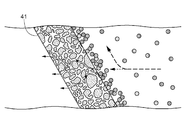
- the vaporizing means 40 includes a plurality of plate-shaped elements 41.
- Each element 41 is composed of a ceramic board which is an example of a porous body. The pores of the ceramic board are smaller than the particle size of the humidifying mist sprayed from the mist nozzle 31.
- each element 41 is installed so as to be separated from each other in the vertical direction, and the lower edge 41b is on the upstream side of the upper edge 41a from the intake port 11 to the discharge port 12 in the ventilation direction. It is arranged in an inclined posture so as to be located at.
- each element 41 is installed so that the front and back surfaces thereof form an angle of, for example, 60 degrees with respect to the horizontal. The angle may be in the range of about 45 to 85 degrees, but it can be adjusted to a state where the unvaporized humidifying mist can be reliably captured with respect to the design wind speed of the air conditioner 10 and the pressure loss is minimized.
- each element 41 the lower edge 41b of the upper element 41 (41A) is formed between the vertically adjacent elements 41 (in FIG. 2, some elements are shown by 41A and 41B for convenience of explanation).
- the lower element 41 (41B) is arranged so as to be located below the upper edge 41a.
- each element 41 can be provided with a ventilation passage having a sufficient size between the elements 41 (41A, 41B) adjacent to each other on the upper and lower sides, the pressure loss when passing through the vaporizing means 40 is reduced to the conventional painting booth. It is smaller than the pressure loss of the eliminator provided in the air conditioner. Therefore, it is not necessary to increase the ventilation cross-sectional area even at a speed higher than the ventilation speed in the conventional air conditioner for a painting booth.
- most of the air containing the unvaporized humidifying mist is the element through the ventilation path between the vertically adjacent elements 41 (41A, 41B). While flowing to the downstream side of 41, it collides with the surface of the porous body constituting the element 41 by the inertial force of the humidifying mist itself, or on the surface due to the electrostatic force of the humidifying mist itself or the porous body itself. Be captured.
- the round object shown on the right side of the element 41 is a humidifying mist, and shows a state of being captured by the surface of the element 41.
- a part of the air containing the unvaporized humidifying mist passes through the pores of the porous body constituting the element 41.
- the unvaporized humidifying mist collides with the surface of the pores by the inertial force of the humidifying mist itself. It is trapped on the surface by the humidifying mist itself or the electrostatic force of the porous body itself.
- the humidifying mist trapped on the surface of the pores is sufficiently vaporized because it promotes contact with the air passing through the pores.
- the temperature / humidity adjusting means 50 includes a cooling means 51 that cools the air that has passed through the vaporizing means 40, and a heating means 52 that heats the air that has been cooled by the cooling means 51.
- the air humidified by the humidifying means 30 can be adjusted by the cooling means 51 and the heating means 52 to have the optimum temperature and humidity for use in the painting booth 60.
- the porous body constituting the element 41 is a ceramic board
- the porous body may be a metal sintered body, and on the surface of the porous body, an unvaporized humidifying mist may be brought into contact with air passing through the pores of the object. Just do it.
- mist nozzle 31 is a one-fluid high-pressure nozzle, but this is not the case.
- the mist nozzle 31 may be a two-fluid nozzle or an ultrasonic atomization nozzle.
- the air conditioner 10 has the heating means 20, the humidifying means 30, the vaporizing means 40, and the temperature / humidity adjusting means 50 inside the housing 13 has been described, but the present invention is not limited to this.
- the air conditioner 10 may be configured not to have the heating means 20 or the temperature / humidity adjusting means 50 inside the housing 13. In this case, the heating means 20 and the temperature / humidity adjusting means 50 may be provided outside the housing 13.
- Air conditioner 11 Intake port 12: Discharge port 13: Housing 20: Heating means 30: Humidifying means 31: Mist nozzle 40: Vaporizing means 41: Element 41a: Upper edge 41b: Lower edge 50: Temperature and humidity control Means 60: Painting booth 62: Object to be coated
Landscapes
- Engineering & Computer Science (AREA)
- Chemical & Material Sciences (AREA)
- Combustion & Propulsion (AREA)
- Mechanical Engineering (AREA)
- General Engineering & Computer Science (AREA)
- Dispersion Chemistry (AREA)
- Details Or Accessories Of Spraying Plant Or Apparatus (AREA)
- Air Humidification (AREA)
Abstract
L'invention concerne un dispositif de climatisation hautement efficace, écoénergétique et compact. Le dispositif de climatisation (10), destiné à alimenter en air une cabine de peinture (60) dans laquelle de la peinture est appliquée à un objet (62) à peindre, est conçu pour comprendre : une enveloppe (13) comportant un orifice d'admission (11) et un orifice d'évacuation (12) permettant l'alimentation en air ; un moyen d'humidification (30) permettant de pulvériser un brouillard d'humidification sur l'air aspiré à travers l'orifice d'admission (11) ; et un moyen de vaporisation (40) permettant de vaporiser le brouillard d'humidification non vaporisé contenu dans l'air à l'aide de la mise en contact du brouillard d'humidification non vaporisé avec l'air, et permettant en même temps le passage de l'air pulvérisé avec le brouillard d'humidification à l'aide du moyen d'humidification (30) à travers ledit moyen de vaporisation. L'air dont l'humidité a été régulée à l'aide du moyen d'humidification (30) et du moyen de vaporisation (40) est alimenté à la cabine de peinture (60) à travers l'orifice d'évacuation (12).
Priority Applications (3)
| Application Number | Priority Date | Filing Date | Title |
|---|---|---|---|
| US17/272,480 US20210325059A1 (en) | 2019-08-05 | 2020-07-28 | Air Conditioner for Paint Booth |
| KR1020217020592A KR102619498B1 (ko) | 2019-08-05 | 2020-07-28 | 도장 부스용의 공조 장치 |
| CN202080004579.2A CN112654434B (zh) | 2019-08-05 | 2020-07-28 | 涂装室用的空调装置 |
Applications Claiming Priority (2)
| Application Number | Priority Date | Filing Date | Title |
|---|---|---|---|
| JP2019143733A JP7341779B2 (ja) | 2019-08-05 | 2019-08-05 | 塗装ブース用の空調装置 |
| JP2019-143733 | 2019-08-05 |
Publications (1)
| Publication Number | Publication Date |
|---|---|
| WO2021024857A1 true WO2021024857A1 (fr) | 2021-02-11 |
Family
ID=74503616
Family Applications (1)
| Application Number | Title | Priority Date | Filing Date |
|---|---|---|---|
| PCT/JP2020/028873 WO2021024857A1 (fr) | 2019-08-05 | 2020-07-28 | Dispositif de climatisation pour cabine de peinture |
Country Status (5)
| Country | Link |
|---|---|
| US (1) | US20210325059A1 (fr) |
| JP (1) | JP7341779B2 (fr) |
| KR (1) | KR102619498B1 (fr) |
| CN (1) | CN112654434B (fr) |
| WO (1) | WO2021024857A1 (fr) |
Citations (7)
| Publication number | Priority date | Publication date | Assignee | Title |
|---|---|---|---|---|
| JPS55114368A (en) * | 1979-02-27 | 1980-09-03 | Nissan Motor Co Ltd | Air conditioner for paint coating |
| JPS56136228U (fr) * | 1980-03-14 | 1981-10-15 | ||
| JPS57165063A (en) * | 1981-04-07 | 1982-10-09 | Nissan Motor Co Ltd | Air-conditioner for coating |
| JPS6354535A (ja) * | 1986-08-22 | 1988-03-08 | Chizuko Ozawa | 冷房装置 |
| JPH0735005U (ja) * | 1993-12-10 | 1995-06-27 | 株式会社ワコー | スプレー式加湿機 |
| JP2012122671A (ja) * | 2010-12-08 | 2012-06-28 | Sanki Eng Co Ltd | 水噴霧加湿装置 |
| JP2015025619A (ja) * | 2013-07-26 | 2015-02-05 | 大阪瓦斯株式会社 | 加湿器 |
Family Cites Families (22)
| Publication number | Priority date | Publication date | Assignee | Title |
|---|---|---|---|---|
| JP3120021B2 (ja) * | 1995-06-19 | 2000-12-25 | クボタ空調株式会社 | 蒸気加湿器 |
| US6059866A (en) * | 1997-09-30 | 2000-05-09 | Sanki Engineering Co., Ltd | Air washer |
| JP2004053238A (ja) * | 2002-07-23 | 2004-02-19 | Shinei Sangyo Kk | 調湿機 |
| CN200952794Y (zh) * | 2006-04-10 | 2007-09-26 | 爱克斯爱尔(北京)加湿系统有限公司 | 中央空调加湿系统 |
| JP4816251B2 (ja) * | 2006-05-26 | 2011-11-16 | マックス株式会社 | 空調装置及び建物 |
| US7291196B1 (en) * | 2006-11-16 | 2007-11-06 | Lerner Bernard J | Filamentary pad for improved mist elimination and mass transfer |
| KR20080056595A (ko) * | 2006-12-18 | 2008-06-23 | 강경형 | 증기발생 장치 |
| WO2008117684A1 (fr) * | 2007-03-28 | 2008-10-02 | Toshiba Carrier Corporation | Humidificateur et climatiseur |
| JP5493814B2 (ja) | 2009-12-16 | 2014-05-14 | マツダ株式会社 | 塗装用空調装置の制御方法及びその装置 |
| US8273158B2 (en) * | 2010-11-29 | 2012-09-25 | General Electric Company | Mist eliminator, moisture removal system, and method of removing water particles from inlet air |
| JP2013213616A (ja) * | 2012-04-02 | 2013-10-17 | Fuji Electric Co Ltd | 気化冷却装置、およびその制御方法 |
| JP5839483B2 (ja) * | 2012-05-29 | 2016-01-06 | トリニティ工業株式会社 | 塗装ブース用空調装置 |
| JP6167326B2 (ja) * | 2013-03-14 | 2017-07-26 | パナソニックIpマネジメント株式会社 | 塗装ミスト処理装置 |
| KR101552874B1 (ko) * | 2015-05-28 | 2015-09-14 | 김정우 | 초입자 분무장치 |
| US9982907B2 (en) * | 2015-07-17 | 2018-05-29 | Valeriy S. Maisotsenko | Method and systems for energy-saving heating and humidifying of buildings using outside air |
| DE102016114466A1 (de) * | 2016-08-04 | 2018-02-08 | Eisenmann Se | Konditioniervorrichtung und Verfahren zum Konditionieren eines gasförmigen Mediums sowie Anlage und Verfahren zum Behandeln von Werkstücken |
| DE102016124478A1 (de) | 2016-12-15 | 2018-06-21 | Eisenmann Se | Vorrichtung zum Befeuchten eines Luftstroms |
| JP2018162909A (ja) | 2017-03-24 | 2018-10-18 | トヨタ自動車株式会社 | 気化式加湿器 |
| KR101938689B1 (ko) * | 2017-04-21 | 2019-04-10 | 한정흠 | 미세먼지포집 및 가습기능을 갖는 에너지 절약형 공기조화기 |
| JP6970962B2 (ja) * | 2017-09-22 | 2021-11-24 | 株式会社Japan Zero | 塗装システム |
| JP2019072695A (ja) * | 2017-10-18 | 2019-05-16 | 株式会社エー・イー・エス | クローズド塗装装置 |
| CN208170612U (zh) * | 2018-03-26 | 2018-11-30 | 维谛技术有限公司 | 一种加湿装置 |
-
2019
- 2019-08-05 JP JP2019143733A patent/JP7341779B2/ja active Active
-
2020
- 2020-07-28 CN CN202080004579.2A patent/CN112654434B/zh active Active
- 2020-07-28 US US17/272,480 patent/US20210325059A1/en active Pending
- 2020-07-28 KR KR1020217020592A patent/KR102619498B1/ko active IP Right Grant
- 2020-07-28 WO PCT/JP2020/028873 patent/WO2021024857A1/fr active Application Filing
Patent Citations (7)
| Publication number | Priority date | Publication date | Assignee | Title |
|---|---|---|---|---|
| JPS55114368A (en) * | 1979-02-27 | 1980-09-03 | Nissan Motor Co Ltd | Air conditioner for paint coating |
| JPS56136228U (fr) * | 1980-03-14 | 1981-10-15 | ||
| JPS57165063A (en) * | 1981-04-07 | 1982-10-09 | Nissan Motor Co Ltd | Air-conditioner for coating |
| JPS6354535A (ja) * | 1986-08-22 | 1988-03-08 | Chizuko Ozawa | 冷房装置 |
| JPH0735005U (ja) * | 1993-12-10 | 1995-06-27 | 株式会社ワコー | スプレー式加湿機 |
| JP2012122671A (ja) * | 2010-12-08 | 2012-06-28 | Sanki Eng Co Ltd | 水噴霧加湿装置 |
| JP2015025619A (ja) * | 2013-07-26 | 2015-02-05 | 大阪瓦斯株式会社 | 加湿器 |
Also Published As
| Publication number | Publication date |
|---|---|
| KR20210099083A (ko) | 2021-08-11 |
| KR102619498B1 (ko) | 2023-12-28 |
| JP2021025697A (ja) | 2021-02-22 |
| US20210325059A1 (en) | 2021-10-21 |
| JP7341779B2 (ja) | 2023-09-11 |
| CN112654434A (zh) | 2021-04-13 |
| CN112654434B (zh) | 2023-02-24 |
Similar Documents
| Publication | Publication Date | Title |
|---|---|---|
| US4544380A (en) | Air conditioner for a coating booth | |
| CA2585093C (fr) | Methode et dispositif permettant d'ameliorer le rendement d'un evaporateur | |
| US11639801B2 (en) | Methods, systems, and devices for humidifying | |
| US5699983A (en) | Atomizing and mixing nozzle for humidification process | |
| US8070138B2 (en) | Sauna apparatus | |
| JP3907255B2 (ja) | エアワッシャ | |
| JP5288776B2 (ja) | 空気調和機 | |
| JP2002372385A (ja) | 熱交換装置 | |
| US20210123695A1 (en) | Heat exchanger with spray nozzle | |
| KR100924960B1 (ko) | 크린룸내 직접분무식 기화가습장치 및 습도제어방법 | |
| WO2021024857A1 (fr) | Dispositif de climatisation pour cabine de peinture | |
| KR100874886B1 (ko) | 크린룸내 직접분무식 기화가습장치 및 습도제어방법 | |
| JP2002322916A (ja) | ガスタービン吸気冷却装置 | |
| KR20120011913A (ko) | 미세분사노즐을 이용한 클린룸의 공조 시스템 | |
| KR101451358B1 (ko) | 크린룸내 직접분무식 기화가습장치의 습도제어방법 | |
| JPH11347331A (ja) | エアワッシャ | |
| JP3544836B2 (ja) | エアワッシャ | |
| WO2011078757A1 (fr) | Procédé et appareil dans un système de ventilation | |
| JPH09239224A (ja) | ガス不純物の除去装置 | |
| WO2020019635A1 (fr) | Machine à température et humidité constantes | |
| JP6831160B2 (ja) | 水噴霧型加湿装置 | |
| CN113062799B (zh) | 一种燃气轮机加湿减排装置及其控制方法 | |
| JP2021025697A5 (fr) | ||
| CN109457205A (zh) | 一种带钢镀后空气加湿冷却方法及冷却系统 | |
| TH2101000850A (th) | เครื่องปรับอากาศสำหรับห้องพ่นสี |
Legal Events
| Date | Code | Title | Description |
|---|---|---|---|
| 121 | Ep: the epo has been informed by wipo that ep was designated in this application |
Ref document number: 20850687 Country of ref document: EP Kind code of ref document: A1 |
|
| ENP | Entry into the national phase |
Ref document number: 20217020592 Country of ref document: KR Kind code of ref document: A |
|
| NENP | Non-entry into the national phase |
Ref country code: DE |
|
| 122 | Ep: pct application non-entry in european phase |
Ref document number: 20850687 Country of ref document: EP Kind code of ref document: A1 |