WO2021024857A1 - Air-conditioning device for paint booth - Google Patents
Air-conditioning device for paint booth Download PDFInfo
- Publication number
- WO2021024857A1 WO2021024857A1 PCT/JP2020/028873 JP2020028873W WO2021024857A1 WO 2021024857 A1 WO2021024857 A1 WO 2021024857A1 JP 2020028873 W JP2020028873 W JP 2020028873W WO 2021024857 A1 WO2021024857 A1 WO 2021024857A1
- Authority
- WO
- WIPO (PCT)
- Prior art keywords
- air
- humidifying
- mist
- air conditioner
- humidification
- Prior art date
Links
Images


Classifications
-
- B—PERFORMING OPERATIONS; TRANSPORTING
- B05—SPRAYING OR ATOMISING IN GENERAL; APPLYING FLUENT MATERIALS TO SURFACES, IN GENERAL
- B05B—SPRAYING APPARATUS; ATOMISING APPARATUS; NOZZLES
- B05B16/00—Spray booths
- B05B16/40—Construction elements specially adapted therefor, e.g. floors, walls or ceilings
-
- F—MECHANICAL ENGINEERING; LIGHTING; HEATING; WEAPONS; BLASTING
- F24—HEATING; RANGES; VENTILATING
- F24F—AIR-CONDITIONING; AIR-HUMIDIFICATION; VENTILATION; USE OF AIR CURRENTS FOR SCREENING
- F24F3/00—Air-conditioning systems in which conditioned primary air is supplied from one or more central stations to distributing units in the rooms or spaces where it may receive secondary treatment; Apparatus specially designed for such systems
- F24F3/044—Systems in which all treatment is given in the central station, i.e. all-air systems
-
- B—PERFORMING OPERATIONS; TRANSPORTING
- B05—SPRAYING OR ATOMISING IN GENERAL; APPLYING FLUENT MATERIALS TO SURFACES, IN GENERAL
- B05B—SPRAYING APPARATUS; ATOMISING APPARATUS; NOZZLES
- B05B14/00—Arrangements for collecting, re-using or eliminating excess spraying material
- B05B14/40—Arrangements for collecting, re-using or eliminating excess spraying material for use in spray booths
- B05B14/43—Arrangements for collecting, re-using or eliminating excess spraying material for use in spray booths by filtering the air charged with excess material
-
- B—PERFORMING OPERATIONS; TRANSPORTING
- B05—SPRAYING OR ATOMISING IN GENERAL; APPLYING FLUENT MATERIALS TO SURFACES, IN GENERAL
- B05B—SPRAYING APPARATUS; ATOMISING APPARATUS; NOZZLES
- B05B16/00—Spray booths
- B05B16/60—Ventilation arrangements specially adapted therefor
-
- B—PERFORMING OPERATIONS; TRANSPORTING
- B05—SPRAYING OR ATOMISING IN GENERAL; APPLYING FLUENT MATERIALS TO SURFACES, IN GENERAL
- B05B—SPRAYING APPARATUS; ATOMISING APPARATUS; NOZZLES
- B05B7/00—Spraying apparatus for discharge of liquids or other fluent materials from two or more sources, e.g. of liquid and air, of powder and gas
- B05B7/0075—Nozzle arrangements in gas streams
-
- F—MECHANICAL ENGINEERING; LIGHTING; HEATING; WEAPONS; BLASTING
- F24—HEATING; RANGES; VENTILATING
- F24F—AIR-CONDITIONING; AIR-HUMIDIFICATION; VENTILATION; USE OF AIR CURRENTS FOR SCREENING
- F24F3/00—Air-conditioning systems in which conditioned primary air is supplied from one or more central stations to distributing units in the rooms or spaces where it may receive secondary treatment; Apparatus specially designed for such systems
- F24F3/12—Air-conditioning systems in which conditioned primary air is supplied from one or more central stations to distributing units in the rooms or spaces where it may receive secondary treatment; Apparatus specially designed for such systems characterised by the treatment of the air otherwise than by heating and cooling
- F24F3/14—Air-conditioning systems in which conditioned primary air is supplied from one or more central stations to distributing units in the rooms or spaces where it may receive secondary treatment; Apparatus specially designed for such systems characterised by the treatment of the air otherwise than by heating and cooling by humidification; by dehumidification
- F24F3/147—Air-conditioning systems in which conditioned primary air is supplied from one or more central stations to distributing units in the rooms or spaces where it may receive secondary treatment; Apparatus specially designed for such systems characterised by the treatment of the air otherwise than by heating and cooling by humidification; by dehumidification with both heat and humidity transfer between supplied and exhausted air
-
- F—MECHANICAL ENGINEERING; LIGHTING; HEATING; WEAPONS; BLASTING
- F24—HEATING; RANGES; VENTILATING
- F24F—AIR-CONDITIONING; AIR-HUMIDIFICATION; VENTILATION; USE OF AIR CURRENTS FOR SCREENING
- F24F3/00—Air-conditioning systems in which conditioned primary air is supplied from one or more central stations to distributing units in the rooms or spaces where it may receive secondary treatment; Apparatus specially designed for such systems
- F24F3/12—Air-conditioning systems in which conditioned primary air is supplied from one or more central stations to distributing units in the rooms or spaces where it may receive secondary treatment; Apparatus specially designed for such systems characterised by the treatment of the air otherwise than by heating and cooling
- F24F3/14—Air-conditioning systems in which conditioned primary air is supplied from one or more central stations to distributing units in the rooms or spaces where it may receive secondary treatment; Apparatus specially designed for such systems characterised by the treatment of the air otherwise than by heating and cooling by humidification; by dehumidification
- F24F3/153—Air-conditioning systems in which conditioned primary air is supplied from one or more central stations to distributing units in the rooms or spaces where it may receive secondary treatment; Apparatus specially designed for such systems characterised by the treatment of the air otherwise than by heating and cooling by humidification; by dehumidification with subsequent heating, i.e. with the air, given the required humidity in the central station, passing a heating element to achieve the required temperature
-
- F—MECHANICAL ENGINEERING; LIGHTING; HEATING; WEAPONS; BLASTING
- F24—HEATING; RANGES; VENTILATING
- F24F—AIR-CONDITIONING; AIR-HUMIDIFICATION; VENTILATION; USE OF AIR CURRENTS FOR SCREENING
- F24F6/00—Air-humidification, e.g. cooling by humidification
- F24F6/02—Air-humidification, e.g. cooling by humidification by evaporation of water in the air
- F24F6/04—Air-humidification, e.g. cooling by humidification by evaporation of water in the air using stationary unheated wet elements
-
- F—MECHANICAL ENGINEERING; LIGHTING; HEATING; WEAPONS; BLASTING
- F24—HEATING; RANGES; VENTILATING
- F24F—AIR-CONDITIONING; AIR-HUMIDIFICATION; VENTILATION; USE OF AIR CURRENTS FOR SCREENING
- F24F6/00—Air-humidification, e.g. cooling by humidification
- F24F6/12—Air-humidification, e.g. cooling by humidification by forming water dispersions in the air
- F24F6/14—Air-humidification, e.g. cooling by humidification by forming water dispersions in the air using nozzles
-
- B—PERFORMING OPERATIONS; TRANSPORTING
- B05—SPRAYING OR ATOMISING IN GENERAL; APPLYING FLUENT MATERIALS TO SURFACES, IN GENERAL
- B05B—SPRAYING APPARATUS; ATOMISING APPARATUS; NOZZLES
- B05B1/00—Nozzles, spray heads or other outlets, with or without auxiliary devices such as valves, heating means
- B05B1/14—Nozzles, spray heads or other outlets, with or without auxiliary devices such as valves, heating means with multiple outlet openings; with strainers in or outside the outlet opening
- B05B1/20—Arrangements of several outlets along elongated bodies, e.g. perforated pipes or troughs, e.g. spray booms; Outlet elements therefor
- B05B1/205—Arrangements of several outlets along elongated bodies, e.g. perforated pipes or troughs, e.g. spray booms; Outlet elements therefor characterised by the longitudinal shape of the elongated body
-
- B—PERFORMING OPERATIONS; TRANSPORTING
- B05—SPRAYING OR ATOMISING IN GENERAL; APPLYING FLUENT MATERIALS TO SURFACES, IN GENERAL
- B05B—SPRAYING APPARATUS; ATOMISING APPARATUS; NOZZLES
- B05B13/00—Machines or plants for applying liquids or other fluent materials to surfaces of objects or other work by spraying, not covered by groups B05B1/00 - B05B11/00
- B05B13/02—Means for supporting work; Arrangement or mounting of spray heads; Adaptation or arrangement of means for feeding work
- B05B13/04—Means for supporting work; Arrangement or mounting of spray heads; Adaptation or arrangement of means for feeding work the spray heads being moved during spraying operation
- B05B13/0431—Means for supporting work; Arrangement or mounting of spray heads; Adaptation or arrangement of means for feeding work the spray heads being moved during spraying operation with spray heads moved by robots or articulated arms, e.g. for applying liquid or other fluent material to 3D-surfaces
-
- B—PERFORMING OPERATIONS; TRANSPORTING
- B05—SPRAYING OR ATOMISING IN GENERAL; APPLYING FLUENT MATERIALS TO SURFACES, IN GENERAL
- B05B—SPRAYING APPARATUS; ATOMISING APPARATUS; NOZZLES
- B05B17/00—Apparatus for spraying or atomising liquids or other fluent materials, not covered by the preceding groups
- B05B17/04—Apparatus for spraying or atomising liquids or other fluent materials, not covered by the preceding groups operating with special methods
- B05B17/06—Apparatus for spraying or atomising liquids or other fluent materials, not covered by the preceding groups operating with special methods using ultrasonic or other kinds of vibrations
-
- B—PERFORMING OPERATIONS; TRANSPORTING
- B05—SPRAYING OR ATOMISING IN GENERAL; APPLYING FLUENT MATERIALS TO SURFACES, IN GENERAL
- B05B—SPRAYING APPARATUS; ATOMISING APPARATUS; NOZZLES
- B05B9/00—Spraying apparatus for discharge of liquids or other fluent material, without essentially mixing with gas or vapour
- B05B9/03—Spraying apparatus for discharge of liquids or other fluent material, without essentially mixing with gas or vapour characterised by means for supplying liquid or other fluent material
- B05B9/04—Spraying apparatus for discharge of liquids or other fluent material, without essentially mixing with gas or vapour characterised by means for supplying liquid or other fluent material with pressurised or compressible container; with pump
- B05B9/0403—Spraying apparatus for discharge of liquids or other fluent material, without essentially mixing with gas or vapour characterised by means for supplying liquid or other fluent material with pressurised or compressible container; with pump with pumps for liquids or other fluent material
- B05B9/0423—Spraying apparatus for discharge of liquids or other fluent material, without essentially mixing with gas or vapour characterised by means for supplying liquid or other fluent material with pressurised or compressible container; with pump with pumps for liquids or other fluent material for supplying liquid or other fluent material to several spraying apparatus
-
- F—MECHANICAL ENGINEERING; LIGHTING; HEATING; WEAPONS; BLASTING
- F24—HEATING; RANGES; VENTILATING
- F24F—AIR-CONDITIONING; AIR-HUMIDIFICATION; VENTILATION; USE OF AIR CURRENTS FOR SCREENING
- F24F6/00—Air-humidification, e.g. cooling by humidification
- F24F6/12—Air-humidification, e.g. cooling by humidification by forming water dispersions in the air
- F24F6/14—Air-humidification, e.g. cooling by humidification by forming water dispersions in the air using nozzles
- F24F2006/146—Air-humidification, e.g. cooling by humidification by forming water dispersions in the air using nozzles using pressurised water for spraying
-
- Y—GENERAL TAGGING OF NEW TECHNOLOGICAL DEVELOPMENTS; GENERAL TAGGING OF CROSS-SECTIONAL TECHNOLOGIES SPANNING OVER SEVERAL SECTIONS OF THE IPC; TECHNICAL SUBJECTS COVERED BY FORMER USPC CROSS-REFERENCE ART COLLECTIONS [XRACs] AND DIGESTS
- Y02—TECHNOLOGIES OR APPLICATIONS FOR MITIGATION OR ADAPTATION AGAINST CLIMATE CHANGE
- Y02B—CLIMATE CHANGE MITIGATION TECHNOLOGIES RELATED TO BUILDINGS, e.g. HOUSING, HOUSE APPLIANCES OR RELATED END-USER APPLICATIONS
- Y02B30/00—Energy efficient heating, ventilation or air conditioning [HVAC]
- Y02B30/54—Free-cooling systems
Definitions
- the present invention relates to an air conditioner that supplies humidified air to a painting booth that paints an object to be coated.
- the painting booth which paints various objects to be coated such as automobile bodies, automobile parts, and other general objects to be coated, is configured so that air is supplied from the air conditioner.
- the air supplied from the air conditioner to the painting booth affects the painting quality of the object to be coated, so its temperature and humidity need to be controlled.
- the air heating means and humidifying means to be supplied to the painting booth are provided inside the housing of the air conditioner.
- an air conditioner 1 for a painting booth is provided with a preheater 23, a washer 24, a cooling coil 26, and a reheater 27 from the upstream side in the ventilation direction of air to be supplied to the painting booth inside the housing.
- a conventional air conditioner it will be referred to as a conventional air conditioner.
- the reference numerals are those in Patent Document 1.
- the washer 24 includes a water storage unit 24a, a circulation pipe 24b, a pump 24c, a solenoid valve 24d, and a water spray unit 24e, and is configured to raise the humidity of the outside air by spraying water on the outside air through the preheater 23. ..
- the conventional air conditioner has a configuration in which a large amount of water is sprayed from the water spray unit 24e provided on the washer 24.
- the water sprayed from the washer 24 has a large particle size of about 440 ⁇ m.
- the pump 24c needs to have sufficient performance to be able to spray a large amount of water, which causes high equipment cost and running cost. Further, it is necessary to have a water tank for collecting the sprayed water for circulation and a configuration for maintaining and managing the water quality in the water tank, and it is necessary to provide a space inside the housing.
- the unvaporized moisture in the air causes dew condensation on the downstream side of the washer 24, in order to avoid this, an eliminator for separating and recovering the unvaporized moisture from the air may be required.
- the eliminator is provided in the housing, the pressure loss inside the housing becomes high, and the ventilation speed inside the housing cannot be increased. Therefore, in order to secure a sufficient amount of air in the painting booth, it is necessary to increase the ventilation cross-sectional area of the housing.
- Patent Document 2 steam spray humidification as disclosed in Patent Document 2
- humidification using a filler or the like as disclosed in Patent Document 3 and high pressure as disclosed in Patent Document 4.
- atomization sprays using atomization conventionally known dry mist humidification, and the like.
- the present invention has been made in view of the above circumstances, and an object of the present invention is to provide an air conditioner with high efficiency, energy saving, and miniaturization.
- the characteristic configuration of the air conditioner according to the present invention for achieving the above object is an air conditioner that supplies air to a painting booth for painting an object to be coated, and the air intake port and the air discharge port to be supplied. While passing the housing having an outlet, the humidifying means for spraying the humidifying mist onto the air taken in through the intake port, and the air sprayed with the humidifying mist by the humidifying means, the said A vaporizing means for bringing the unvaporized humidifying mist contained in the air into contact with the air to vaporize it is provided, and the humidifying means and the air whose humidity is adjusted by the vaporizing means are passed through the discharge port to the painting booth.
- the point is that it is configured to be supplied to.
- the humidifying mist has a particle size (100 ⁇ m or less, preferably about 30 ⁇ m) that is extremely small compared to the particle size (about 440 ⁇ m) of water that has been sprayed from a washer in the past.
- the humidifying mist that humidifies the air to be supplied to the painting booth has a large vaporization rate because it has a large contact area with the air. Therefore, the ventilation path inside the housing can be made shorter than that of the conventional air conditioner.
- the air conditioner according to the present invention can achieve a size reduction of about 10% in the ventilation direction of the air from the intake port to the discharge port as compared with the conventional air conditioner. ..
- the smaller the particle size the larger the relative surface area, so it can be efficiently contacted with the air.
- the smaller the particle size the smaller the amount of water required. Even with the minimum amount of water required for humidification, it is possible to humidify the air efficiently and with good control response. Therefore, the power of the pump used for this can be small, and the equipment cost and running cost can be reduced. Can be reduced.
- the air conditioner according to the present invention can achieve energy saving of about 90% in the power of the pump as compared with the conventional air conditioner.
- the degree of freedom in arranging the nozzles for spraying the humidifying mist is increased, so that the piping connected to the nozzles can be easily routed.
- the unvaporized humidifying mist existing in the air in the form of droplets is captured and captured without being vaporized only by contact with the air.
- the contact between the humidifying mist and the air passing through the vaporizing means is promoted.
- the unvaporized humidifying mist is sufficiently vaporized.
- the supersaturated state is leveled when passing through the vaporizing means. The risk of dew condensation on the downstream side of the vaporizing means is avoided.
- the air conditioner according to the present invention does not require a water tank as described above, the cost for maintaining the water quality of the water tank, which is required in the conventional air conditioner, is no longer required.
- the vaporizing means includes a plurality of plate-shaped elements, and the elements are installed apart from each other in the vertical direction, and the lower edge is more than the upper edge from the intake port.
- the lower edge of the upper element is the upper edge of the lower element. It is preferable that it is arranged so as to be located below.
- the air conditioner according to the present invention can achieve a size reduction of about 40% in the ventilation cross-sectional area of the air from the intake port to the discharge port as compared with the conventional air conditioner. It was.
- the element is composed of a porous body having pores capable of capturing the humidified mist on its surface while allowing the air containing the unvaporized humidified mist to pass through. is there.
- the unvaporized humidifying mist is applied to the surface of the porous body constituting the element or to the surface of the pores when the air containing the unvaporized humidifying mist passes through the holes. It collides with the humidifying mist itself due to the inertial force, or is trapped on the surface by the electrostatic force of the humidifying mist itself or the porous body itself.
- the humidifying mist trapped in the pores is sufficiently vaporized because the contact with the air passing through the pores is promoted on the surface of the pores.
- the porous body include a ceramic board and a metal sintered body from the viewpoint of easy availability and processing.
- a heating means for heating the air taken in through the intake port before reaching the humidifying means is provided.
- the air taken in through the intake port can be heated by the heating means so as to have an optimum temperature for humidification by the humidifying means.
- the temperature of the air to be taken into the housing is not constant and the temperature of the air taken in through the intake port is not constant, it is necessary to finely change the humidification conditions by the humidifying means. ..
- the humidification temperature by heating the air to a temperature preferable to the humidification condition by the humidification temperature, it is possible to efficiently humidify while keeping the humidification condition of the humidification means constant.
- the temperature / humidity adjusting means for adjusting the temperature / humidity of the air whose humidity has been adjusted by the humidifying means before being discharged from the discharge port is provided.
- the air heated by the heating means and humidified by the humidifying means can be adjusted by the temperature and humidity adjusting means so as to have the optimum temperature and humidity for use in the painting booth. ..
- the temperature / humidity adjusting means may be exemplified by a cooling means and a heating means, and either one of them may be provided or both may be provided. In this case, it is preferable that the cooling means is provided on the upstream side in the ventilation direction of the air rather than the heating means.
- FIG. 1 is an explanatory diagram of an air conditioner according to the present invention.
- FIG. 2 is an explanatory diagram of a humidifying means and a vaporizing means.
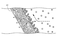
- FIG. 3 is an explanatory view of a main part of the air conditioner.
- the object to be coated 62 is painted by spraying the paint from the coating machine 61. Is done.
- air whose temperature and humidity are controlled by the air conditioner 10 is supplied in order to ensure the painting quality of the object to be coated 62.
- the supplied air also serves to capture the paint mist that has been oversprayed and scattered from the coating machine 61.
- the air conditioner 10 has a heating means 20, a humidifying means 30, a vaporizing means 40, and a temperature / humidity adjusting means 50 inside a housing 13 having an air intake port 11 and a discharge port 12 outside the air conditioner 10. It is provided.
- the heating means 20 is provided to heat the temperature of the air taken in through the intake port 11 to a temperature suitable for humidification by the humidifying means 30.
- the humidifying means 30 has a mist nozzle 31 and a pump 32 or the like that supplies water to the mist nozzle 31, and sprays the water supplied from the pump 32 from the mist nozzle 31 in the form of a humidifying mist having a particle size of about 30 ⁇ m or less. As a result, it is configured to humidify the air adjusted to an appropriate temperature by the heating means 20.
- the mist nozzle 31 is composed of a one-fluid high-pressure nozzle. In the present embodiment, the mist nozzle 31 is arranged so as to spray the humidifying mist toward the downstream side in the ventilation direction of the air.
- the vaporizing means 40 includes a plurality of plate-shaped elements 41.
- Each element 41 is composed of a ceramic board which is an example of a porous body. The pores of the ceramic board are smaller than the particle size of the humidifying mist sprayed from the mist nozzle 31.
- each element 41 is installed so as to be separated from each other in the vertical direction, and the lower edge 41b is on the upstream side of the upper edge 41a from the intake port 11 to the discharge port 12 in the ventilation direction. It is arranged in an inclined posture so as to be located at.
- each element 41 is installed so that the front and back surfaces thereof form an angle of, for example, 60 degrees with respect to the horizontal. The angle may be in the range of about 45 to 85 degrees, but it can be adjusted to a state where the unvaporized humidifying mist can be reliably captured with respect to the design wind speed of the air conditioner 10 and the pressure loss is minimized.
- each element 41 the lower edge 41b of the upper element 41 (41A) is formed between the vertically adjacent elements 41 (in FIG. 2, some elements are shown by 41A and 41B for convenience of explanation).
- the lower element 41 (41B) is arranged so as to be located below the upper edge 41a.
- each element 41 can be provided with a ventilation passage having a sufficient size between the elements 41 (41A, 41B) adjacent to each other on the upper and lower sides, the pressure loss when passing through the vaporizing means 40 is reduced to the conventional painting booth. It is smaller than the pressure loss of the eliminator provided in the air conditioner. Therefore, it is not necessary to increase the ventilation cross-sectional area even at a speed higher than the ventilation speed in the conventional air conditioner for a painting booth.
- most of the air containing the unvaporized humidifying mist is the element through the ventilation path between the vertically adjacent elements 41 (41A, 41B). While flowing to the downstream side of 41, it collides with the surface of the porous body constituting the element 41 by the inertial force of the humidifying mist itself, or on the surface due to the electrostatic force of the humidifying mist itself or the porous body itself. Be captured.
- the round object shown on the right side of the element 41 is a humidifying mist, and shows a state of being captured by the surface of the element 41.
- a part of the air containing the unvaporized humidifying mist passes through the pores of the porous body constituting the element 41.
- the unvaporized humidifying mist collides with the surface of the pores by the inertial force of the humidifying mist itself. It is trapped on the surface by the humidifying mist itself or the electrostatic force of the porous body itself.
- the humidifying mist trapped on the surface of the pores is sufficiently vaporized because it promotes contact with the air passing through the pores.
- the temperature / humidity adjusting means 50 includes a cooling means 51 that cools the air that has passed through the vaporizing means 40, and a heating means 52 that heats the air that has been cooled by the cooling means 51.
- the air humidified by the humidifying means 30 can be adjusted by the cooling means 51 and the heating means 52 to have the optimum temperature and humidity for use in the painting booth 60.
- the porous body constituting the element 41 is a ceramic board
- the porous body may be a metal sintered body, and on the surface of the porous body, an unvaporized humidifying mist may be brought into contact with air passing through the pores of the object. Just do it.
- mist nozzle 31 is a one-fluid high-pressure nozzle, but this is not the case.
- the mist nozzle 31 may be a two-fluid nozzle or an ultrasonic atomization nozzle.
- the air conditioner 10 has the heating means 20, the humidifying means 30, the vaporizing means 40, and the temperature / humidity adjusting means 50 inside the housing 13 has been described, but the present invention is not limited to this.
- the air conditioner 10 may be configured not to have the heating means 20 or the temperature / humidity adjusting means 50 inside the housing 13. In this case, the heating means 20 and the temperature / humidity adjusting means 50 may be provided outside the housing 13.
- Air conditioner 11 Intake port 12: Discharge port 13: Housing 20: Heating means 30: Humidifying means 31: Mist nozzle 40: Vaporizing means 41: Element 41a: Upper edge 41b: Lower edge 50: Temperature and humidity control Means 60: Painting booth 62: Object to be coated
Abstract
Provided is an air-conditioning device that is highly efficient, energy-saving, and compact. An air-conditioning device 10 which supplies air to a paint booth 60 where paint is applied to an object 62 to be painted is configured by being provided with: a housing 13 that has an intake port 11 and a discharge port 12 for air to be supplied; a humidification means 30 for spraying a humidification mist on the air drawn in through the intake port 11; and a vaporization means 40 for vaporizing the unvaporized humidification mist contained in the air by bringing the unvaporized humidification mist into contact with the air while allowing the air sprayed with the humidification mist by the humidification means 30 to pass through. The air that has been humidity-regulated by the humidification means 30 and the vaporization means 40 is supplied to the paint booth 60 through the discharge port 12.
Description
本発明は、被塗物に塗装を行う塗装ブースに加湿された空気を供給する空調装置に関する。
The present invention relates to an air conditioner that supplies humidified air to a painting booth that paints an object to be coated.
自動車車体、自動車部品、その他一般被塗物などの各種被塗物に塗装を行う塗装ブースには空調装置から空気が供給されるように構成されている。
The painting booth, which paints various objects to be coated such as automobile bodies, automobile parts, and other general objects to be coated, is configured so that air is supplied from the air conditioner.
当該空調装置から塗装ブースに供給される空気は、被塗物に対する塗装品質に影響を与えるため、その温湿度は制御されている必要がある。
The air supplied from the air conditioner to the painting booth affects the painting quality of the object to be coated, so its temperature and humidity need to be controlled.
空気の温湿度の制御を可能とするために、空調装置の筐体の内部には塗装ブースへ供給されるべき空気の加温手段や加湿手段等が設けられている。
In order to control the temperature and humidity of the air, the air heating means and humidifying means to be supplied to the painting booth are provided inside the housing of the air conditioner.
例えば、特許文献1には、筐体の内部に塗装ブースへ供給されるべき空気の通風方向上流側からプレヒータ23、ワッシャ24、クーリングコイル26及びレヒータ27が設けられた塗装ブース用空調装置1(以下、従来の空調装置と記す。)が開示されている。なお、符号は特許文献1におけるものである。
For example, in Patent Document 1, an air conditioner 1 for a painting booth is provided with a preheater 23, a washer 24, a cooling coil 26, and a reheater 27 from the upstream side in the ventilation direction of air to be supplied to the painting booth inside the housing. Hereinafter, it will be referred to as a conventional air conditioner). The reference numerals are those in Patent Document 1.
当該ワッシャ24は、水貯留部24a、循環用配管24b、ポンプ24c、電磁弁24d、水噴霧部24eを備え、プレヒータ23を経た外気に対する水の噴霧により外気の湿度を上げるように構成されている。
The washer 24 includes a water storage unit 24a, a circulation pipe 24b, a pump 24c, a solenoid valve 24d, and a water spray unit 24e, and is configured to raise the humidity of the outside air by spraying water on the outside air through the preheater 23. ..
しかし、従来の空調装置は、ワッシャ24に備えられた水噴霧部24eから大量の水を噴霧する構成である。ワッシャ24から噴霧される水は粒子径が440μm程度と大きい。このような水によって空気を加湿するためには、水と空気との接触時間を確保する必要があり、そのため通風路を長くする必要があった。さらに、粒子径の大きな水によって効率的な加湿をするためには、水噴霧部24eにおけるノズルの配列や循環用配管24bの取り回しを考慮する必要があった。
However, the conventional air conditioner has a configuration in which a large amount of water is sprayed from the water spray unit 24e provided on the washer 24. The water sprayed from the washer 24 has a large particle size of about 440 μm. In order to humidify the air with such water, it is necessary to secure the contact time between the water and the air, and therefore it is necessary to lengthen the ventilation path. Further, in order to efficiently humidify with water having a large particle size, it is necessary to consider the arrangement of nozzles in the water spray unit 24e and the layout of the circulation pipe 24b.
また、ポンプ24cは、大量の水を噴霧可能とするために充分な性能を有する必要があり、設備コストや、ランニングコストが高くなる原因となっていた。さらに、噴霧した水を循環させるために回収する水槽や、水槽内の水質の維持管理のための構成が必要であり、そのスペースを筐体の内部に設ける必要があった。
In addition, the pump 24c needs to have sufficient performance to be able to spray a large amount of water, which causes high equipment cost and running cost. Further, it is necessary to have a water tank for collecting the sprayed water for circulation and a configuration for maintaining and managing the water quality in the water tank, and it is necessary to provide a space inside the housing.
また、空気中の未気化の水分はワッシャ24の下流側において結露を生じさせるため、これを回避するためには、空気中から未気化の水分を分離回収するエリミネータが必要となる場合がある。しかし、エリミネータを筐体に設けると、筐体の内部における圧力損失が高くなってしまい、筐体の内部における通風速度を高めることができない。そのため、塗装ブースにおいて必要な空気量を充分確保するためには、筐体の通風断面積を大きくする必要があった。
Further, since the unvaporized moisture in the air causes dew condensation on the downstream side of the washer 24, in order to avoid this, an eliminator for separating and recovering the unvaporized moisture from the air may be required. However, if the eliminator is provided in the housing, the pressure loss inside the housing becomes high, and the ventilation speed inside the housing cannot be increased. Therefore, in order to secure a sufficient amount of air in the painting booth, it is necessary to increase the ventilation cross-sectional area of the housing.
以上のように、従来の空調装置は、高効率化、省エネルギー化及び小型化の観点において改善の余地があった。
As described above, there is room for improvement in the conventional air conditioner from the viewpoint of high efficiency, energy saving and miniaturization.
さらに、ワッシャを用いる構成以外にも、特許文献2に開示されるような蒸気噴霧加湿、特許文献3に開示されるような充填材等を用いた加湿、特許文献4に開示されるような高圧霧化を利用した霧化スプレー、従来から公知のドライミスト加湿等がある。
Further, in addition to the configuration using a washer, steam spray humidification as disclosed in Patent Document 2, humidification using a filler or the like as disclosed in Patent Document 3, and high pressure as disclosed in Patent Document 4. There are atomization sprays using atomization, conventionally known dry mist humidification, and the like.
しかし、特許文献2に開示されるような蒸気噴霧加湿については、蒸気コストが大きく、ランニングコストが増大したり、蒸気エネルギー効率が悪く、省エネにならなかったり、局所的に過飽和となるため下流側装置内で結露が発生しやすい、といった問題がある。
However, with regard to steam spray humidification as disclosed in Patent Document 2, the steam cost is high, the running cost is increased, the steam energy efficiency is poor, energy saving is not achieved, and local supersaturation occurs, so that the downstream side There is a problem that dew condensation is likely to occur in the device.
特許文献3に開示されるような充填材等を用いた加湿については、充填材に保有水ができるため制御応答性が悪かったり、充填材種類によっては気液接触面積を大きくとろうとすると加湿器部分に大きなスペースが必要となる、といった問題がある。
Regarding humidification using a filler or the like as disclosed in Patent Document 3, the control response is poor because the filler contains water, and depending on the type of filler, the humidifier is used to increase the gas-liquid contact area. There is a problem that a large space is required in the part.
特許文献4に開示されるような高圧霧化スプレーについては、水受け槽を有する場合には空調器を小さくすることができなかったり、噴霧ノズルの下流側に噴霧ミストの気化距離が必要であるため、空調器を小型化することができない、といった問題がある。
Regarding the high-pressure atomization spray as disclosed in Patent Document 4, when the water receiving tank is provided, the air conditioner cannot be made small, or the vaporization distance of the spray mist is required on the downstream side of the spray nozzle. Therefore, there is a problem that the air conditioner cannot be miniaturized.
従来から公知のドライミスト加湿については、噴霧ノズルの下流側に噴霧ミストの気化距離が必要であるため、空調器を小型化することができなかったり、局所的に過飽和や噴霧ミストの気化が不十分なポイントができやすく、下流側装置内に結露が発生しやすい、といった問題がある。
Conventionally known dry mist humidification requires a vaporization distance of the spray mist on the downstream side of the spray nozzle, so that the air conditioner cannot be miniaturized, or local supersaturation or vaporization of the spray mist is not possible. There is a problem that sufficient points are easily formed and dew condensation is likely to occur in the downstream device.
本発明は上記実情に鑑みてなされたものであって、高効率化、省エネルギー化及び小型化が図られた空調装置を提供することを目的とする
The present invention has been made in view of the above circumstances, and an object of the present invention is to provide an air conditioner with high efficiency, energy saving, and miniaturization.
上述の目的を達成するための本発明に係る空調装置の特徴構成は、被塗物に塗装を行う塗装ブースに空気を供給する空調装置であって、当該供給すべき空気の取込口及び吐出口を有する筐体と、前記取込口を介して取り込まれた前記空気に対して加湿ミストを噴霧する加湿手段と、前記加湿手段によって前記加湿ミストが噴霧された前記空気を通過させながら、前記空気に含まれる未気化の加湿ミストを前記空気と接触させて気化させる気化手段とが設けられ、前記加湿手段及び前記気化手段によって湿度調節がされた前記空気が前記吐出口を介して前記塗装ブースに供給されるように構成されている点にある。
The characteristic configuration of the air conditioner according to the present invention for achieving the above object is an air conditioner that supplies air to a painting booth for painting an object to be coated, and the air intake port and the air discharge port to be supplied. While passing the housing having an outlet, the humidifying means for spraying the humidifying mist onto the air taken in through the intake port, and the air sprayed with the humidifying mist by the humidifying means, the said A vaporizing means for bringing the unvaporized humidifying mist contained in the air into contact with the air to vaporize it is provided, and the humidifying means and the air whose humidity is adjusted by the vaporizing means are passed through the discharge port to the painting booth. The point is that it is configured to be supplied to.
なお、加湿ミストとは、その粒子径が、従来ワッシャから噴霧されていた水の粒子径(440μm程度)に比べて極めて小さい粒子径(100μm以下、好ましくは30μm程度)を有するものをいう。
The humidifying mist has a particle size (100 μm or less, preferably about 30 μm) that is extremely small compared to the particle size (about 440 μm) of water that has been sprayed from a washer in the past.
したがって、塗装ブースに供給されるべき前記空気を加湿する加湿ミストは、当該空気との接触面積が多いことから気化速度が速い。そのため、従来の空調装置より前記筐体の内部における通風路を短くすることができる。本発明に係る空調装置は、上述の構成により、従来の空調装置に比べて、前記取込口から前記吐出口へ向かう前記空気の通風方向において10%程度のサイズダウンを達成することができた。
Therefore, the humidifying mist that humidifies the air to be supplied to the painting booth has a large vaporization rate because it has a large contact area with the air. Therefore, the ventilation path inside the housing can be made shorter than that of the conventional air conditioner. With the above configuration, the air conditioner according to the present invention can achieve a size reduction of about 10% in the ventilation direction of the air from the intake port to the discharge port as compared with the conventional air conditioner. ..
同量の水を用いて加湿するにあたり、その粒子径が小さいほど相対的な表面積は大きくなるため、効率よく前記空気と接触させることができる。つまり、同程度の加湿であれば、粒子径が小さいほうが、少しの水量でこれが可能となる。加湿に必要な最低限の水量であっても、効率的かつ制御応答性の良好な前記空気の加湿が可能であることから、これに用いるポンプの動力は小さなもので良く、設備コスト及びランニングコストの低減を図ることができる。
When humidifying with the same amount of water, the smaller the particle size, the larger the relative surface area, so it can be efficiently contacted with the air. In other words, with the same degree of humidification, the smaller the particle size, the smaller the amount of water required. Even with the minimum amount of water required for humidification, it is possible to humidify the air efficiently and with good control response. Therefore, the power of the pump used for this can be small, and the equipment cost and running cost can be reduced. Can be reduced.
本発明に係る空調装置は、上述の構成により、従来の空調装置に比べて、ポンプの動力において90%程度の省エネルギー化を達成することができるようになった。また、効率的かつ制御応答性の良好な前記空気の加湿が可能であることから、加湿ミストを噴霧するノズルの配列の自由度が高まるため、ノズルにつながる配管の取り回し性がよい。
With the above configuration, the air conditioner according to the present invention can achieve energy saving of about 90% in the power of the pump as compared with the conventional air conditioner. In addition, since it is possible to humidify the air with good efficiency and control response, the degree of freedom in arranging the nozzles for spraying the humidifying mist is increased, so that the piping connected to the nozzles can be easily routed.
前記加湿手段の下流側に設けられた前記気化手段においては、前記空気との接触だけでは気化されずに、液滴状で当該空気中に存在する未気化の加湿ミストが捕捉され、この捕捉された加湿ミストと、前記気化手段を通過する前記空気との接触が促される。これにより、未気化の加湿ミストは充分に気化させられる。また、前記加湿手段による前記空気の加湿によって当該空気に局所的な過飽和状態の部分が発生している場合であっても、当該気化手段を通過する際に当該過飽和状態が均されるため、前記気化手段の下流側において結露が発生するような虞が回避される。
In the vaporizing means provided on the downstream side of the humidifying means, the unvaporized humidifying mist existing in the air in the form of droplets is captured and captured without being vaporized only by contact with the air. The contact between the humidifying mist and the air passing through the vaporizing means is promoted. As a result, the unvaporized humidifying mist is sufficiently vaporized. Further, even when a locally supersaturated portion is generated in the air due to the humidification of the air by the humidifying means, the supersaturated state is leveled when passing through the vaporizing means. The risk of dew condensation on the downstream side of the vaporizing means is avoided.
したがって、従来の空調装置のように水槽やエリミネータを前記筐体の内部に設ける必要がなく、したがって、その分のスペースを確保する必要がない。本発明に係る空調装置は、上述のように水槽が不要となることから、従来の空調装置において必要であった水槽の水質の維持管理のための費用が不要となった。
Therefore, unlike a conventional air conditioner, it is not necessary to provide a water tank or an eliminator inside the housing, and therefore it is not necessary to secure a space for that amount. Since the air conditioner according to the present invention does not require a water tank as described above, the cost for maintaining the water quality of the water tank, which is required in the conventional air conditioner, is no longer required.
以上のように、空調装置における加湿の高効率化、設備コスト及びランニングコストの省エネルギー化や小型化が達成される。
As described above, high efficiency of humidification in the air conditioner, energy saving of equipment cost and running cost, and miniaturization are achieved.
また、蒸気噴霧をしないことから蒸気噴霧加湿が有する問題が発生せず、充填材等を用いないことから充填材等を用いた加湿が有する問題が発生せず、高圧霧化スプレーを用いないことから高圧霧化を利用した霧化スプレーが有する問題が発生せず、気化手段が設けられていることからドライミスト加湿が有する問題が発生しない。
In addition, since the steam spray is not used, the problem of steam spray humidification does not occur, and since the filler is not used, the problem of humidification using the filler is not generated, and the high-pressure atomization spray is not used. Therefore, the problem of the atomizing spray using high-pressure atomization does not occur, and the problem of dry mist humidification does not occur because the vaporizing means is provided.
本発明においては、前記気化手段は、複数枚の板状のエレメントを備え、前記各エレメントは、上下方向に互いに離間して設置されるとともに、下縁が上縁よりも前記取込口から前記吐出口へ向かう前記空気の通風方向の上流側に位置するように傾斜姿勢で配置され、かつ、上下に隣り合うエレメントどうしにおいて、上側の前記エレメントの下縁が、下側の前記エレメントの上縁よりも下方に位置するように配置されていると好適である。
In the present invention, the vaporizing means includes a plurality of plate-shaped elements, and the elements are installed apart from each other in the vertical direction, and the lower edge is more than the upper edge from the intake port. Among the elements that are arranged in an inclined posture so as to be located on the upstream side in the ventilation direction of the air toward the discharge port and that are adjacent to each other in the vertical direction, the lower edge of the upper element is the upper edge of the lower element. It is preferable that it is arranged so as to be located below.
これにより、上側のエレメントと下側のエレメントとの間において、前記取込口から前記吐出口へと直線的に至る通風路をなくしながらも、上下に隣り合うエレメントどうしの間に十分な大きさの通風路を設けることができる。そのため、前記気化手段を通過させる際の圧力損失は、従来の空調装置に設けられるエリミネータの圧力損失よりも小さい。したがって、従来の空調装置における通風速度より速い速度であっても、通風断面積を大きくする必要がない。本発明に係る空調装置は、上述の構成により、従来の空調装置に比べて、前記取込口から前記吐出口へ向かう前記空気の通風断面積において約40%のサイズダウンを達成することができた。
As a result, between the upper element and the lower element, there is no ventilation path that linearly extends from the intake port to the discharge port, but the size is sufficiently large between the vertically adjacent elements. Ventilation channels can be provided. Therefore, the pressure loss when passing through the vaporizing means is smaller than the pressure loss of the eliminator provided in the conventional air conditioner. Therefore, it is not necessary to increase the ventilation cross-sectional area even at a speed higher than the ventilation speed in the conventional air conditioner. With the above configuration, the air conditioner according to the present invention can achieve a size reduction of about 40% in the ventilation cross-sectional area of the air from the intake port to the discharge port as compared with the conventional air conditioner. It was.
また、上側のエレメントと下側のエレメントとの間に、前記取込口から前記吐出口へと直線的に至る通風路が存在しない。したがって、未気化の加湿ミストが、エレメントに接触することなく前記吐出口に至ってしまう虞が低減されている。
Further, there is no ventilation path linearly extending from the intake port to the discharge port between the upper element and the lower element. Therefore, the possibility that the unvaporized humidifying mist reaches the discharge port without contacting the element is reduced.
本発明においては、前記エレメントは、前記未気化の加湿ミストを含んだ前記空気を通過させながら、前記加湿ミストをその表面において捕捉可能な空孔を有する多孔質体から構成されていると好適である。
In the present invention, it is preferable that the element is composed of a porous body having pores capable of capturing the humidified mist on its surface while allowing the air containing the unvaporized humidified mist to pass through. is there.
上述の構成によると、未気化の加湿ミストは、エレメントを構成する多孔質体の表面や、当該未気化の加湿ミストを含んだ前記空気が空孔を通過する際に、当該空孔の表面に当該加湿ミスト自身の慣性力によって衝突したり、当該加湿ミスト自身や多孔質体自身の静電気力等によって、当該表面において捕捉される。当該空孔に捕捉された加湿ミストは当該空孔の表面において当該空孔を通過する前記空気との接触が促されるため、十分に気化される。なお、多孔質体は、入手及び加工の容易性の観点からセラミックボードや金属焼結体が例示できる。
According to the above configuration, the unvaporized humidifying mist is applied to the surface of the porous body constituting the element or to the surface of the pores when the air containing the unvaporized humidifying mist passes through the holes. It collides with the humidifying mist itself due to the inertial force, or is trapped on the surface by the electrostatic force of the humidifying mist itself or the porous body itself. The humidifying mist trapped in the pores is sufficiently vaporized because the contact with the air passing through the pores is promoted on the surface of the pores. Examples of the porous body include a ceramic board and a metal sintered body from the viewpoint of easy availability and processing.
本発明においては、前記取込口を介して取り込まれた前記空気を、前記加湿手段に至る前に加温する加温手段が設けられていると好適である。
In the present invention, it is preferable that a heating means for heating the air taken in through the intake port before reaching the humidifying means is provided.
上述の構成によると、前記取込口を介して取り込まれた前記空気を、前記加湿手段による加湿に最適な温度となるように、加温手段によって加温することができる。前記筐体に取り込まれるべき前記空気の温度は一定ではなく、前記取込口を介して取り込まれた前記空気の温度が一定でない場合は、前記加湿手段による加湿の条件を細かく変動させる必要がある。これに対して、加湿温度による加湿の条件に好ましい温度まで前記空気を加温することによって、前記加湿手段の加湿の条件を一定にしたまま、効率よく加湿をすることができる。
According to the above configuration, the air taken in through the intake port can be heated by the heating means so as to have an optimum temperature for humidification by the humidifying means. When the temperature of the air to be taken into the housing is not constant and the temperature of the air taken in through the intake port is not constant, it is necessary to finely change the humidification conditions by the humidifying means. .. On the other hand, by heating the air to a temperature preferable to the humidification condition by the humidification temperature, it is possible to efficiently humidify while keeping the humidification condition of the humidification means constant.
本発明においては、前記加湿手段によって湿度調節された前記空気を、前記吐出口から吐出される前に温湿度調節する温湿度調節手段が設けられていると好適である。
In the present invention, it is preferable that the temperature / humidity adjusting means for adjusting the temperature / humidity of the air whose humidity has been adjusted by the humidifying means before being discharged from the discharge port is provided.
上述の構成によると、加温手段によって加温され、前記加湿手段によって加湿された前記空気を、塗装ブースで用いるのに最適な温湿度となるように、温湿度調節手段によって調節することができる。
According to the above configuration, the air heated by the heating means and humidified by the humidifying means can be adjusted by the temperature and humidity adjusting means so as to have the optimum temperature and humidity for use in the painting booth. ..
なお、温湿度調節手段は、冷却手段や加熱手段が例示でき、これらいずれか一方が設けられる構成であってもよいし、両方が設けられる構成であってもよい。この場合は、冷却手段が加熱手段よりも、前記空気の通風方向の上流側に設けられることが好ましい。
The temperature / humidity adjusting means may be exemplified by a cooling means and a heating means, and either one of them may be provided or both may be provided. In this case, it is preferable that the cooling means is provided on the upstream side in the ventilation direction of the air rather than the heating means.
以下に、本発明に係る空調装置の実施形態について、図面を参照しながら説明をする。
The embodiment of the air conditioner according to the present invention will be described below with reference to the drawings.
図1に示すように、自動車車体、自動車部品、その他一般被塗物などの各種被塗物に塗装を行う塗装ブース60においては、塗装機61から塗料を噴霧することで被塗物62の塗装が行われる。
As shown in FIG. 1, in the painting booth 60 for painting various objects to be coated such as an automobile body, automobile parts, and other general objects to be coated, the object to be coated 62 is painted by spraying the paint from the coating machine 61. Is done.
塗装ブース60においては、被塗物62に対する塗装品質を確保するために、空調装置10によって温湿度が制御された空気が供給されている。
In the painting booth 60, air whose temperature and humidity are controlled by the air conditioner 10 is supplied in order to ensure the painting quality of the object to be coated 62.
当該供給された空気は、塗装機61からオーバースプレーされ飛散した塗料ミストを捕捉する役目も果たしている。
The supplied air also serves to capture the paint mist that has been oversprayed and scattered from the coating machine 61.
空調装置10は、当該空調装置10の外部の空気の取込口11及び吐出口12を有する筐体13の内部に、加温手段20、加湿手段30、気化手段40及び温湿度調節手段50が設けられている。
The air conditioner 10 has a heating means 20, a humidifying means 30, a vaporizing means 40, and a temperature / humidity adjusting means 50 inside a housing 13 having an air intake port 11 and a discharge port 12 outside the air conditioner 10. It is provided.
加温手段20は、取込口11を介して取り込まれた空気の温度を、加湿手段30による加湿に適した温度にまで加温するために設けられている。
The heating means 20 is provided to heat the temperature of the air taken in through the intake port 11 to a temperature suitable for humidification by the humidifying means 30.
加湿手段30は、ミストノズル31及びミストノズル31に水を供給するポンプ32等を有し、ポンプ32から供給された水をミストノズル31から粒子径が30μm程度以下の加湿ミストの態様によって噴霧することによって、加温手段20によって適温に調節された空気を加湿するように構成されている。ミストノズル31は、一流体型高圧ノズルから構成されている。本実施形態においては、ミストノズル31は、当該空気の通風方向の下流側に向けて加湿ミストを噴霧するように配置されている。
The humidifying means 30 has a mist nozzle 31 and a pump 32 or the like that supplies water to the mist nozzle 31, and sprays the water supplied from the pump 32 from the mist nozzle 31 in the form of a humidifying mist having a particle size of about 30 μm or less. As a result, it is configured to humidify the air adjusted to an appropriate temperature by the heating means 20. The mist nozzle 31 is composed of a one-fluid high-pressure nozzle. In the present embodiment, the mist nozzle 31 is arranged so as to spray the humidifying mist toward the downstream side in the ventilation direction of the air.
気化手段40は、複数枚の板状のエレメント41を備えて構成される。各エレメント41は多孔質体の一例であるセラミックボードから構成される。セラミックボードが有する空孔は、ミストノズル31から噴霧される加湿ミストの粒子径よりも小さい。
The vaporizing means 40 includes a plurality of plate-shaped elements 41. Each element 41 is composed of a ceramic board which is an example of a porous body. The pores of the ceramic board are smaller than the particle size of the humidifying mist sprayed from the mist nozzle 31.
図2に示すように、各エレメント41は、上下方向に互いに離間して設置されるとともに、下縁41bが上縁41aよりも取込口11から吐出口12へ向かう空気の通風方向の上流側に位置するように傾斜姿勢で配置されている。本実施形態においては、各エレメント41は、その表裏面が水平に対して例えば60度の角度をなすように設置される。当該角度は、45~85度程度の範囲内にあればよいが、空調装置10の設計風速に対して確実に未気化の加湿ミストを捕捉でき、かつ、圧力損失が最も小さくなる状態に調節できる構造を有する。
As shown in FIG. 2, each element 41 is installed so as to be separated from each other in the vertical direction, and the lower edge 41b is on the upstream side of the upper edge 41a from the intake port 11 to the discharge port 12 in the ventilation direction. It is arranged in an inclined posture so as to be located at. In the present embodiment, each element 41 is installed so that the front and back surfaces thereof form an angle of, for example, 60 degrees with respect to the horizontal. The angle may be in the range of about 45 to 85 degrees, but it can be adjusted to a state where the unvaporized humidifying mist can be reliably captured with respect to the design wind speed of the air conditioner 10 and the pressure loss is minimized. Has a structure.
また、各エレメント41は、上下に隣り合うエレメント41(図2において、一部のエレメントを説明の便宜のため41A、41Bで示す。)どうしにおいて、上側のエレメント41(41A)の下縁41bが、下側のエレメント41(41B)の上縁41aよりも下方に位置するように配置されている。
Further, in each element 41, the lower edge 41b of the upper element 41 (41A) is formed between the vertically adjacent elements 41 (in FIG. 2, some elements are shown by 41A and 41B for convenience of explanation). , The lower element 41 (41B) is arranged so as to be located below the upper edge 41a.
この構成によって、上側のエレメント41(41A)と下側のエレメント41(41B)との間に、取込口11から吐出口12へと直線的に至る通風路が存在しないため、未気化の加湿ミストが、エレメント41に接触することなく吐出口12に至ってしまう虞が低減されている。
Due to this configuration, there is no ventilation path linearly extending from the intake port 11 to the discharge port 12 between the upper element 41 (41A) and the lower element 41 (41B), so that the humidification is not vaporized. The possibility that the mist will reach the discharge port 12 without coming into contact with the element 41 is reduced.
各エレメント41は、上下に隣り合うエレメント41(41A、41B)どうしの間に十分な大きさの通風路を設けることができるため、気化手段40を通過させる際の圧力損失は、従来の塗装ブース用空調装置に設けられるエリミネータの圧力損失に比べて小さい。そのため、従来の塗装ブース用空調装置における通風速度より速い速度であっても、通風断面積を大きくする必要がない。
Since each element 41 can be provided with a ventilation passage having a sufficient size between the elements 41 (41A, 41B) adjacent to each other on the upper and lower sides, the pressure loss when passing through the vaporizing means 40 is reduced to the conventional painting booth. It is smaller than the pressure loss of the eliminator provided in the air conditioner. Therefore, it is not necessary to increase the ventilation cross-sectional area even at a speed higher than the ventilation speed in the conventional air conditioner for a painting booth.
図3において、太い破線矢印で流れを示すように、未気化の加湿ミストを含んだ空気のうち大部分は、上下に隣り合うエレメント41(41A、41B)どうしの間の通風路を介してエレメント41の下流側に流れるうちに、エレメント41を構成する多孔質体の表面に当該加湿ミスト自身の慣性力によって衝突したり、当該加湿ミスト自身や多孔質体自身の静電気力等によって、当該表面において捕捉される。なお、図3において、エレメント41の右側において示される丸い物体は加湿ミストであって、エレメント41の表面に捕捉されている様子を表す。
In FIG. 3, as shown by the thick dashed arrow, most of the air containing the unvaporized humidifying mist is the element through the ventilation path between the vertically adjacent elements 41 (41A, 41B). While flowing to the downstream side of 41, it collides with the surface of the porous body constituting the element 41 by the inertial force of the humidifying mist itself, or on the surface due to the electrostatic force of the humidifying mist itself or the porous body itself. Be captured. In FIG. 3, the round object shown on the right side of the element 41 is a humidifying mist, and shows a state of being captured by the surface of the element 41.
また、図3において、細い破線矢印で流れを示すように、未気化の加湿ミストを含んだ空気のうち一部は、エレメント41を構成する多孔質体の空孔を通過するのであるが、当該未気化の加湿ミストは、当該未気化の加湿ミストを含んだ空気がエレメント41を構成する多孔質体の空孔を通過する際に、当該空孔の表面に当該加湿ミスト自身の慣性力によって衝突したり、当該加湿ミスト自身や多孔質体自身の静電気力等によって、当該表面において捕捉される。当該空孔の表面に捕捉された加湿ミストは、当該空孔を通過する空気との接触が促されるため、十分に気化される。
Further, in FIG. 3, as shown by the thin broken arrow, a part of the air containing the unvaporized humidifying mist passes through the pores of the porous body constituting the element 41. When the air containing the unvaporized humidifying mist passes through the pores of the porous body constituting the element 41, the unvaporized humidifying mist collides with the surface of the pores by the inertial force of the humidifying mist itself. It is trapped on the surface by the humidifying mist itself or the electrostatic force of the porous body itself. The humidifying mist trapped on the surface of the pores is sufficiently vaporized because it promotes contact with the air passing through the pores.
温湿度調節手段50は、気化手段40を経た空気を冷却する冷却手段51と、冷却手段51によって冷却された当該空気を加熱する加熱手段52を備えている。加湿手段30によって加湿された空気を、冷却手段51及び加熱手段52によって、塗装ブース60で用いるのに最適な温湿度となるように調節することができる。
The temperature / humidity adjusting means 50 includes a cooling means 51 that cools the air that has passed through the vaporizing means 40, and a heating means 52 that heats the air that has been cooled by the cooling means 51. The air humidified by the humidifying means 30 can be adjusted by the cooling means 51 and the heating means 52 to have the optimum temperature and humidity for use in the painting booth 60.
上述した実施形態においては、エレメント41を構成する多孔質体がセラミックボードである場合について説明したが、この限りではない。例えば、多孔質体は、金属焼結体であってもよく、当該多孔質体の表面において、未気化の加湿ミストを当該物体の空孔を通過する空気と接触をさせることができるものであればよい。
In the above-described embodiment, the case where the porous body constituting the element 41 is a ceramic board has been described, but this is not the case. For example, the porous body may be a metal sintered body, and on the surface of the porous body, an unvaporized humidifying mist may be brought into contact with air passing through the pores of the object. Just do it.
上述した実施形態においては、ミストノズル31が一流体型高圧ノズルである場合について説明したが、この限りではない。ミストノズル31は二流体型ノズルであってもよいし、超音波式微粒化ノズルであってもよい。
In the above-described embodiment, the case where the mist nozzle 31 is a one-fluid high-pressure nozzle has been described, but this is not the case. The mist nozzle 31 may be a two-fluid nozzle or an ultrasonic atomization nozzle.
上述した実施形態においては、空調装置10が、筐体13の内部に、加温手段20、加湿手段30、気化手段40及び温湿度調節手段50を有する場合について説明したが、この限りではない。空調装置10は、筐体13の内部に加温手段20や温湿度調節手段50を有していない構成であってもよい。この場合は、加温手段20や温湿度調節手段50を筐体13の外部に有してもよい。
In the above-described embodiment, the case where the air conditioner 10 has the heating means 20, the humidifying means 30, the vaporizing means 40, and the temperature / humidity adjusting means 50 inside the housing 13 has been described, but the present invention is not limited to this. The air conditioner 10 may be configured not to have the heating means 20 or the temperature / humidity adjusting means 50 inside the housing 13. In this case, the heating means 20 and the temperature / humidity adjusting means 50 may be provided outside the housing 13.
上述した実施形態は、いずれも本発明の一例であり、当該記載により本発明が限定されるものではなく、各部の具体的構成は本発明の作用効果が奏される範囲において適宜変更設計可能である。
The above-described embodiments are all examples of the present invention, and the description does not limit the present invention, and the specific configuration of each part can be appropriately modified and designed within the range in which the effects of the present invention are exhibited. is there.
10 :空調装置
11 :取込口
12 :吐出口
13 :筐体
20 :加温手段
30 :加湿手段
31 :ミストノズル
40 :気化手段
41 :エレメント
41a :上縁
41b :下縁
50 :温湿度調節手段
60 :塗装ブース
62 :被塗物 10: Air conditioner 11: Intake port 12: Discharge port 13: Housing 20: Heating means 30: Humidifying means 31: Mist nozzle 40: Vaporizing means 41:Element 41a: Upper edge 41b: Lower edge 50: Temperature and humidity control Means 60: Painting booth 62: Object to be coated
11 :取込口
12 :吐出口
13 :筐体
20 :加温手段
30 :加湿手段
31 :ミストノズル
40 :気化手段
41 :エレメント
41a :上縁
41b :下縁
50 :温湿度調節手段
60 :塗装ブース
62 :被塗物 10: Air conditioner 11: Intake port 12: Discharge port 13: Housing 20: Heating means 30: Humidifying means 31: Mist nozzle 40: Vaporizing means 41:
Claims (5)
- 被塗物に塗装を行う塗装ブースに空気を供給する空調装置であって、
当該供給すべき空気の取込口及び吐出口を有する筐体と、
前記取込口を介して取り込まれた前記空気に対して加湿ミストを噴霧する加湿手段と、
前記加湿手段によって前記加湿ミストが噴霧された前記空気を通過させながら、前記空気に含まれる未気化の加湿ミストを前記空気と接触させて気化させる気化手段とが設けられ、
前記加湿手段及び前記気化手段によって湿度調節がされた前記空気が前記吐出口を介して前記塗装ブースに供給されるように構成されている空調装置。 An air conditioner that supplies air to a painting booth that paints objects to be painted.
A housing having an intake port and a discharge port for the air to be supplied,
A humidifying means for spraying a humidifying mist on the air taken in through the intake port, and
The humidifying means is provided with a vaporizing means for vaporizing the unvaporized humidifying mist contained in the air by contacting it with the air while passing the air sprayed with the humidifying mist.
An air conditioner configured so that the air whose humidity is controlled by the humidifying means and the vaporizing means is supplied to the painting booth through the discharge port. - 前記気化手段は、複数枚の板状のエレメントを備え、
前記各エレメントは、上下方向に互いに離間して設置されるとともに、下縁が上縁よりも前記取込口から前記吐出口へ向かう前記空気の通風方向の上流側に位置するように傾斜姿勢で配置され、かつ、上下に隣り合うエレメントどうしにおいて、上側の前記エレメントの下縁が、下側の前記エレメントの上縁よりも下方に位置するように配置されている請求項1に記載の空調装置。 The vaporizing means includes a plurality of plate-shaped elements and comprises a plurality of plate-shaped elements.
The elements are installed so as to be separated from each other in the vertical direction, and in an inclined posture so that the lower edge is located upstream of the upper edge in the ventilation direction of the air from the intake port to the discharge port. The air conditioner according to claim 1, wherein the lower edge of the upper element is arranged below the upper edge of the lower element among the elements arranged one above the other and adjacent to each other. .. - 前記エレメントは、前記未気化の加湿ミストを含んだ前記空気を通過させながら、前記加湿ミストをその表面において捕捉可能な空孔を有する多孔質体から構成されている請求項2に記載の空調装置。 The air conditioner according to claim 2, wherein the element is composed of a porous body having pores capable of capturing the humidified mist on its surface while allowing the air containing the unvaporized humidified mist to pass through. ..
- 前記取込口を介して取り込まれた前記空気を、前記加湿手段に至る前に加温する加温手段が設けられている請求項1から3のいずれか一項に記載の空調装置。 The air conditioner according to any one of claims 1 to 3, wherein a heating means for heating the air taken in through the intake port before reaching the humidifying means is provided.
- 前記加湿手段によって湿度調節された前記空気を、前記吐出口から吐出される前に温湿度調節する温湿度調節手段が設けられている請求項1から4のいずれか一項に記載の空調装置。 The air conditioner according to any one of claims 1 to 4, provided with a temperature / humidity adjusting means for adjusting the temperature / humidity of the air whose humidity has been adjusted by the humidifying means before being discharged from the discharge port.
Priority Applications (3)
| Application Number | Priority Date | Filing Date | Title |
|---|---|---|---|
| US17/272,480 US20210325059A1 (en) | 2019-08-05 | 2020-07-28 | Air Conditioner for Paint Booth |
| KR1020217020592A KR102619498B1 (en) | 2019-08-05 | 2020-07-28 | Air conditioning equipment for painting booths |
| CN202080004579.2A CN112654434B (en) | 2019-08-05 | 2020-07-28 | Air conditioner for coating room |
Applications Claiming Priority (2)
| Application Number | Priority Date | Filing Date | Title |
|---|---|---|---|
| JP2019-143733 | 2019-08-05 | ||
| JP2019143733A JP7341779B2 (en) | 2019-08-05 | 2019-08-05 | Air conditioner for paint booth |
Publications (1)
| Publication Number | Publication Date |
|---|---|
| WO2021024857A1 true WO2021024857A1 (en) | 2021-02-11 |
Family
ID=74503616
Family Applications (1)
| Application Number | Title | Priority Date | Filing Date |
|---|---|---|---|
| PCT/JP2020/028873 WO2021024857A1 (en) | 2019-08-05 | 2020-07-28 | Air-conditioning device for paint booth |
Country Status (5)
| Country | Link |
|---|---|
| US (1) | US20210325059A1 (en) |
| JP (1) | JP7341779B2 (en) |
| KR (1) | KR102619498B1 (en) |
| CN (1) | CN112654434B (en) |
| WO (1) | WO2021024857A1 (en) |
Citations (7)
| Publication number | Priority date | Publication date | Assignee | Title |
|---|---|---|---|---|
| JPS55114368A (en) * | 1979-02-27 | 1980-09-03 | Nissan Motor Co Ltd | Air conditioner for paint coating |
| JPS56136228U (en) * | 1980-03-14 | 1981-10-15 | ||
| JPS57165063A (en) * | 1981-04-07 | 1982-10-09 | Nissan Motor Co Ltd | Air-conditioner for coating |
| JPS6354535A (en) * | 1986-08-22 | 1988-03-08 | Chizuko Ozawa | Cooling apparatus |
| JPH0735005U (en) * | 1993-12-10 | 1995-06-27 | 株式会社ワコー | Spray humidifier |
| JP2012122671A (en) * | 2010-12-08 | 2012-06-28 | Sanki Eng Co Ltd | Water spray humidifying device |
| JP2015025619A (en) * | 2013-07-26 | 2015-02-05 | 大阪瓦斯株式会社 | Humidifier |
Family Cites Families (22)
| Publication number | Priority date | Publication date | Assignee | Title |
|---|---|---|---|---|
| JP3120021B2 (en) * | 1995-06-19 | 2000-12-25 | クボタ空調株式会社 | Steam humidifier |
| US6059866A (en) * | 1997-09-30 | 2000-05-09 | Sanki Engineering Co., Ltd | Air washer |
| JP2004053238A (en) * | 2002-07-23 | 2004-02-19 | Shinei Sangyo Kk | Humidity controller |
| CN200952794Y (en) * | 2006-04-10 | 2007-09-26 | 爱克斯爱尔(北京)加湿系统有限公司 | Central air conditioner humidifying system |
| JP4816251B2 (en) * | 2006-05-26 | 2011-11-16 | マックス株式会社 | Air conditioner and building |
| US7291196B1 (en) * | 2006-11-16 | 2007-11-06 | Lerner Bernard J | Filamentary pad for improved mist elimination and mass transfer |
| KR20080056595A (en) * | 2006-12-18 | 2008-06-23 | 강경형 | Apparatus of producing the vapor |
| JPWO2008117684A1 (en) * | 2007-03-28 | 2010-07-15 | 東芝キヤリア株式会社 | Humidifier and air conditioner |
| JP5493814B2 (en) | 2009-12-16 | 2014-05-14 | マツダ株式会社 | Control method and apparatus for coating air conditioner |
| US8273158B2 (en) * | 2010-11-29 | 2012-09-25 | General Electric Company | Mist eliminator, moisture removal system, and method of removing water particles from inlet air |
| JP2013213616A (en) * | 2012-04-02 | 2013-10-17 | Fuji Electric Co Ltd | Evaporative cooling device and method of controlling the same |
| JP5839483B2 (en) | 2012-05-29 | 2016-01-06 | トリニティ工業株式会社 | Air conditioner for painting booth |
| JP6167326B2 (en) * | 2013-03-14 | 2017-07-26 | パナソニックIpマネジメント株式会社 | Paint mist processing equipment |
| KR101552874B1 (en) * | 2015-05-28 | 2015-09-14 | 김정우 | Supermicellar Atomizing Device |
| US9982907B2 (en) * | 2015-07-17 | 2018-05-29 | Valeriy S. Maisotsenko | Method and systems for energy-saving heating and humidifying of buildings using outside air |
| DE102016114466A1 (en) * | 2016-08-04 | 2018-02-08 | Eisenmann Se | Conditioning device and method for conditioning a gaseous medium and system and method for treating workpieces |
| DE102016124478A1 (en) | 2016-12-15 | 2018-06-21 | Eisenmann Se | Device for humidifying an air flow |
| JP2018162909A (en) | 2017-03-24 | 2018-10-18 | トヨタ自動車株式会社 | Vaporization type humidifier |
| KR101938689B1 (en) * | 2017-04-21 | 2019-04-10 | 한정흠 | Energy-saving type thermo-hygrostat with collection of ultrafine particles and humidification |
| JP6970962B2 (en) * | 2017-09-22 | 2021-11-24 | 株式会社Japan Zero | Painting system |
| JP2019072695A (en) * | 2017-10-18 | 2019-05-16 | 株式会社エー・イー・エス | Closed coating apparatus |
| CN208170612U (en) * | 2018-03-26 | 2018-11-30 | 维谛技术有限公司 | A kind of humidifier |
-
2019
- 2019-08-05 JP JP2019143733A patent/JP7341779B2/en active Active
-
2020
- 2020-07-28 WO PCT/JP2020/028873 patent/WO2021024857A1/en active Application Filing
- 2020-07-28 KR KR1020217020592A patent/KR102619498B1/en active IP Right Grant
- 2020-07-28 CN CN202080004579.2A patent/CN112654434B/en active Active
- 2020-07-28 US US17/272,480 patent/US20210325059A1/en active Pending
Patent Citations (7)
| Publication number | Priority date | Publication date | Assignee | Title |
|---|---|---|---|---|
| JPS55114368A (en) * | 1979-02-27 | 1980-09-03 | Nissan Motor Co Ltd | Air conditioner for paint coating |
| JPS56136228U (en) * | 1980-03-14 | 1981-10-15 | ||
| JPS57165063A (en) * | 1981-04-07 | 1982-10-09 | Nissan Motor Co Ltd | Air-conditioner for coating |
| JPS6354535A (en) * | 1986-08-22 | 1988-03-08 | Chizuko Ozawa | Cooling apparatus |
| JPH0735005U (en) * | 1993-12-10 | 1995-06-27 | 株式会社ワコー | Spray humidifier |
| JP2012122671A (en) * | 2010-12-08 | 2012-06-28 | Sanki Eng Co Ltd | Water spray humidifying device |
| JP2015025619A (en) * | 2013-07-26 | 2015-02-05 | 大阪瓦斯株式会社 | Humidifier |
Also Published As
| Publication number | Publication date |
|---|---|
| KR102619498B1 (en) | 2023-12-28 |
| CN112654434B (en) | 2023-02-24 |
| CN112654434A (en) | 2021-04-13 |
| JP2021025697A (en) | 2021-02-22 |
| US20210325059A1 (en) | 2021-10-21 |
| KR20210099083A (en) | 2021-08-11 |
| JP7341779B2 (en) | 2023-09-11 |
Similar Documents
| Publication | Publication Date | Title |
|---|---|---|
| US4544380A (en) | Air conditioner for a coating booth | |
| CA2585093C (en) | Method and apparatus for improving evaporator performance | |
| US20200378639A1 (en) | Methods, systems, and devices for humidifying | |
| US5699983A (en) | Atomizing and mixing nozzle for humidification process | |
| JPH06193923A (en) | Air humidifier | |
| US8070138B2 (en) | Sauna apparatus | |
| JP3907255B2 (en) | Air washer | |
| JP2002372385A (en) | Heat exchanging system | |
| US20210123695A1 (en) | Heat exchanger with spray nozzle | |
| KR100924960B1 (en) | A vaporization humidification device | |
| WO2021024857A1 (en) | Air-conditioning device for paint booth | |
| KR100874886B1 (en) | A vaporization humidification device | |
| KR101451358B1 (en) | A vaporization humidification device | |
| JP2002322916A (en) | Cooling apparatus of gas turbine suction air | |
| JPH11347331A (en) | Air washer | |
| JP3544836B2 (en) | Air washer | |
| EP2516934A1 (en) | A method and an apparatus in a ventilation system | |
| JPH09239224A (en) | Apparatus for removing gas impurity | |
| WO2020019635A1 (en) | Constant temperature and humidity machine | |
| JP6831160B2 (en) | Water spray type humidifier | |
| CN113062799B (en) | Humidification and emission reduction device of gas turbine and control method thereof | |
| JP2021025697A5 (en) | ||
| CN109457205A (en) | Air wetting cooling means and cooling system after a kind of plating of strip | |
| TH2101000850A (en) | Air conditioner for painting room | |
| WO2023241099A1 (en) | Electronic atomization device and heating assembly thereof |
Legal Events
| Date | Code | Title | Description |
|---|---|---|---|
| 121 | Ep: the epo has been informed by wipo that ep was designated in this application |
Ref document number: 20850687 Country of ref document: EP Kind code of ref document: A1 |
|
| ENP | Entry into the national phase |
Ref document number: 20217020592 Country of ref document: KR Kind code of ref document: A |
|
| NENP | Non-entry into the national phase |
Ref country code: DE |
|
| 122 | Ep: pct application non-entry in european phase |
Ref document number: 20850687 Country of ref document: EP Kind code of ref document: A1 |