WO2021024481A1 - 障害物検出装置 - Google Patents
障害物検出装置 Download PDFInfo
- Publication number
- WO2021024481A1 WO2021024481A1 PCT/JP2019/031481 JP2019031481W WO2021024481A1 WO 2021024481 A1 WO2021024481 A1 WO 2021024481A1 JP 2019031481 W JP2019031481 W JP 2019031481W WO 2021024481 A1 WO2021024481 A1 WO 2021024481A1
- Authority
- WO
- WIPO (PCT)
- Prior art keywords
- distance measuring
- obstacle
- obstacle detection
- unit
- propagation path
- Prior art date
- Legal status (The legal status is an assumption and is not a legal conclusion. Google has not performed a legal analysis and makes no representation as to the accuracy of the status listed.)
- Ceased
Links
Images











Classifications
-
- G—PHYSICS
- G01—MEASURING; TESTING
- G01S—RADIO DIRECTION-FINDING; RADIO NAVIGATION; DETERMINING DISTANCE OR VELOCITY BY USE OF RADIO WAVES; LOCATING OR PRESENCE-DETECTING BY USE OF THE REFLECTION OR RERADIATION OF RADIO WAVES; ANALOGOUS ARRANGEMENTS USING OTHER WAVES
- G01S15/00—Systems using the reflection or reradiation of acoustic waves, e.g. sonar systems
- G01S15/02—Systems using the reflection or reradiation of acoustic waves, e.g. sonar systems using reflection of acoustic waves
- G01S15/06—Systems determining the position data of a target
- G01S15/42—Simultaneous measurement of distance and other co-ordinates
-
- G—PHYSICS
- G01—MEASURING; TESTING
- G01S—RADIO DIRECTION-FINDING; RADIO NAVIGATION; DETERMINING DISTANCE OR VELOCITY BY USE OF RADIO WAVES; LOCATING OR PRESENCE-DETECTING BY USE OF THE REFLECTION OR RERADIATION OF RADIO WAVES; ANALOGOUS ARRANGEMENTS USING OTHER WAVES
- G01S15/00—Systems using the reflection or reradiation of acoustic waves, e.g. sonar systems
- G01S15/88—Sonar systems specially adapted for specific applications
- G01S15/93—Sonar systems specially adapted for specific applications for anti-collision purposes
Definitions
- the present invention relates to an obstacle detection device.
- a device for detecting an obstacle around the vehicle that is, an obstacle detection device has been developed by using a group of distance measuring sensors provided in the vehicle.
- a technique has been developed for estimating the position and size of an obstacle in the area in front of the vehicle by so-called “aperture synthesis" using a group of distance measuring sensors provided at the front end of the vehicle.
- aperture synthesis a technique for estimating the position and size of an obstacle in the area in front of the vehicle.
- a technique has been developed in which the position and size of an obstacle in a region behind the vehicle are estimated by aperture synthesis using a group of distance measuring sensors provided at the rear end of the vehicle.
- Patent Document 1 discloses such a collision avoidance device.
- the conventional obstacle detection device from the viewpoint of avoiding the occurrence of interference in the distance measuring sensor group, a plurality of distance measuring sensors included in the distance measuring sensor group are sequentially driven one by one. Therefore, as will be described later with reference to FIGS. 8 to 10, there is a problem that the estimation of the position and size of the obstacle is delayed. Further, as will be described later with reference to FIGS. 14 and 15, there is a problem that the estimation accuracy of the position and size of the obstacle is lowered, particularly when the obstacle is a moving body.
- the present invention has been made to solve the above problems, and an object of the present invention is to provide an obstacle detection device capable of estimating the position and size of an obstacle at an early stage.
- the position of the obstacle and the position of the obstacle and the position of the obstacle are determined by the distance measuring sensor group for the vehicle, the distance measuring unit that executes the distance measuring processing by the distance measuring sensor group, and the aperture synthesis based on the result of the distance measuring processing.
- It is equipped with an obstacle detection unit that executes obstacle detection processing including a processing for estimating the size, and an output control unit that outputs a signal indicating the result of the obstacle detection processing, and has a plurality of distance measuring sensors. It is composed of one distance measuring sensor and a plurality of second distance measuring sensors, and a plurality of first distance measuring sensors and a plurality of second distance measuring sensors are alternately arranged, and a plurality of second distance measuring sensors are arranged alternately.
- the first ranging sensor selected from the plurality of first ranging sensors in a state where the first frequency corresponding to the one ranging sensor is different from the second frequency corresponding to the plurality of second ranging sensors. And the second ranging sensor selected from the plurality of second ranging sensors is driven at the same time.
- the position and size of the obstacle can be estimated at an early stage.
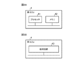
- FIG. 5A is an explanatory diagram showing a hardware configuration of the first ECU in the obstacle detection device according to the first embodiment.
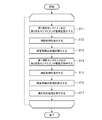
- FIG. 5B is an explanatory diagram showing another hardware configuration of the first ECU in the obstacle detection device according to the first embodiment. It is a flowchart which shows the operation of the 1st ECU in the obstacle detection apparatus which concerns on Embodiment 1.
- FIG. It is explanatory drawing which shows the example of the installation position in the vehicle of a plurality of distance measurement sensors used in the conventional obstacle detection device.
- FIG. 8A is an explanatory diagram showing an example of an ultrasonic wave propagation path when the first drive process in the conventional obstacle detection device is executed.
- FIG. 8B is an explanatory diagram showing an example of an ultrasonic wave propagation path when the second drive process in the conventional obstacle detection device is executed.
- FIG. 8C is an explanatory diagram showing an example of an ultrasonic wave propagation path when the third drive process in the conventional obstacle detection device is executed.
- FIG. 8D is an explanatory diagram showing an example of the ultrasonic wave propagation path when the fourth drive process in the conventional obstacle detection device is executed.
- FIG. 9A is an explanatory diagram showing another example of the ultrasonic wave propagation path when the first drive process in the conventional obstacle detection device is executed.
- FIG. 9B is an explanatory diagram showing another example of the ultrasonic wave propagation path when the second drive process in the conventional obstacle detection device is executed.
- FIG. 9C is an explanatory diagram showing another example of the ultrasonic wave propagation path when the third drive process in the conventional obstacle detection device is executed.
- FIG. 9A is an explanatory diagram showing another example of the ultrasonic wave propagation path when the first drive process in the conventional obstacle detection device is executed.
- FIG. 9B is an explanatory diagram showing another example of the ultrasonic wave propagation path when the second drive
- FIG. 10A is an explanatory diagram showing another example of the ultrasonic wave propagation path when the first drive process in the conventional obstacle detection device is executed.
- FIG. 10B is an explanatory diagram showing another example of the ultrasonic wave propagation path when the second drive process in the conventional obstacle detection device is executed.
- FIG. 10C is an explanatory diagram showing another example of the ultrasonic wave propagation path when the third drive process in the conventional obstacle detection device is executed.
- FIG. 10D is an explanatory diagram showing another example of the ultrasonic wave propagation path when the fourth drive process in the conventional obstacle detection device is executed.
- FIG. 10A is an explanatory diagram showing another example of the ultrasonic wave propagation path when the first drive process in the conventional obstacle detection device is executed.
- FIG. 10B is an explanatory diagram showing another example of the ultrasonic wave propagation path when the second drive process in the conventional obstacle detection device is executed.
- FIG. 10C is an explanatory diagram showing another example of the ultrasonic wave propagation path when the third drive
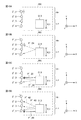
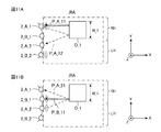
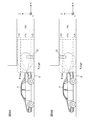
- FIG. 11A is an explanatory diagram showing an example of an ultrasonic wave propagation path when the first drive process is executed in the obstacle detection device according to the first embodiment.
- FIG. 11B is an explanatory diagram showing an example of an ultrasonic wave propagation path when the second drive process is executed in the obstacle detection device according to the first embodiment.
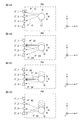
- FIG. 12A is an explanatory diagram showing another example of the ultrasonic wave propagation path when the first drive process is executed in the obstacle detection device according to the first embodiment.
- FIG. 12B is an explanatory diagram showing another example of the ultrasonic wave propagation path when the second drive process is executed in the obstacle detection device according to the first embodiment.
- FIG. 13A is an explanatory diagram showing another example of the ultrasonic wave propagation path when the first drive process is executed in the obstacle detection device according to the first embodiment.
- FIG. 13B is an explanatory diagram showing another example of the ultrasonic wave propagation path when the second drive process is executed in the obstacle detection device according to the first embodiment.
- FIG. 14A is an explanatory diagram showing another example of the ultrasonic wave propagation path when the first drive process in the conventional obstacle detection device is executed.
- FIG. 14B is an explanatory diagram showing another example of the ultrasonic wave propagation path when the second drive process in the conventional obstacle detection device is executed.
- FIG. 14C is an explanatory diagram showing another example of the ultrasonic wave propagation path when the third drive process in the conventional obstacle detection device is executed.
- FIG. 14D is an explanatory diagram showing another example of the ultrasonic wave propagation path when the fourth drive process in the conventional obstacle detection device is executed. It is explanatory drawing which shows the example of the estimation result of the position and size of an obstacle based on the result of the 1st, 2nd, 3rd and 4th distance measurement processing in the conventional obstacle detection apparatus.
- FIG. 16A is an explanatory diagram showing another example of the ultrasonic wave propagation path when the first drive process is executed in the obstacle detection device according to the first embodiment.
- FIG. 16B is an explanatory diagram showing another example of the ultrasonic wave propagation path when the second drive process is executed in the obstacle detection device according to the first embodiment.
- FIG. 16C is an explanatory diagram showing an example of an ultrasonic wave propagation path when the third drive process is executed in the obstacle detection device according to the first embodiment.
- FIG. 16D is an explanatory diagram showing an example of an ultrasonic wave propagation path when the fourth drive process is executed in the obstacle detection device according to the first embodiment.
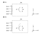
- FIG. 17A is an explanatory diagram showing an example of an estimation result of the position and size of an obstacle based on the results of the first and second distance measurement processes in the obstacle detection device according to the first embodiment.
- FIG. 17B is an explanatory diagram showing an example of an estimation result of the position and size of an obstacle based on the results of the third and fourth distance measurement processes in the obstacle detection device according to the first embodiment.
- FIG. It is explanatory drawing which shows the other example of the installation position in the vehicle of the plurality of distance measurement sensors used for the obstacle detection apparatus which concerns on Embodiment 1.
- FIG. It is a block diagram which shows the main part of another obstacle detection part in the obstacle detection device which concerns on Embodiment 1.
- FIG. It is a block diagram which shows the main part of the collision avoidance apparatus which used the obstacle detection apparatus which concerns on Embodiment 2.
- FIG. It is a block diagram which shows the main part of each distance measuring sensor used in the obstacle detection apparatus which concerns on Embodiment 2.
- FIG. It is a flowchart which shows the operation of the 1st ECU in the obstacle detection apparatus which concerns on Embodiment 2.
- FIG. 24A is an explanatory diagram showing an example of an ultrasonic wave propagation path when the first drive process is executed in the obstacle detection device according to the third embodiment.
- FIG. 24B is an explanatory diagram showing an example of an ultrasonic wave propagation path when the second drive process is executed in the obstacle detection device according to the third embodiment.
- FIG. 25A is an explanatory diagram showing another example of the ultrasonic wave propagation path when the first drive process is executed in the obstacle detection device according to the third embodiment.
- FIG. 24A is an explanatory diagram showing an example of an ultrasonic wave propagation path when the first drive process is executed in the obstacle detection device according to the third embodiment.
- FIG. 25B is an explanatory diagram showing another example of the ultrasonic wave propagation path when the second drive process is executed in the obstacle detection device according to the third embodiment.
- FIG. 26A is an explanatory diagram showing another example of the ultrasonic wave propagation path when the first drive process is executed in the obstacle detection device according to the third embodiment.
- FIG. 26B is an explanatory diagram showing another example of the ultrasonic wave propagation path when the second drive process is executed in the obstacle detection device according to the third embodiment.
- It is a flowchart which shows the operation of the 1st ECU in the obstacle detection apparatus which concerns on Embodiment 3.
- It is a block diagram which shows the main part of the collision avoidance apparatus which used the obstacle detection apparatus which concerns on Embodiment 4.
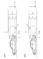
- FIG. 29A is an explanatory diagram showing an example of a state in which a low-profile obstacle exists in the lower region.
- FIG. 29B is an explanatory view showing an example of a state in which a low-profile obstacle exists in the upper region.
- FIG. 30A is an explanatory view showing an example of a state in which a tall obstacle exists over the lower region and the front region.
- FIG. 30B is an explanatory view showing an example of a state in which a tall obstacle exists over the upper region and the front region. It is a flowchart which shows the operation of the 1st ECU in the obstacle detection apparatus which concerns on Embodiment 4.
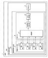
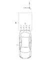
- FIG. 1 is an explanatory diagram showing an example of installation positions of a plurality of distance measuring sensors used in the obstacle detection device according to the first embodiment in a vehicle.
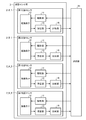
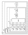
- FIG. 2 is a block diagram showing a main part of a collision avoidance device using the obstacle detection device according to the first embodiment.
- FIG. 3 is a block diagram showing a main part of each distance measuring sensor used in the obstacle detection device according to the first embodiment.
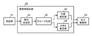
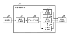
- FIG. 4 is a block diagram showing a main part of the obstacle detection unit in the obstacle detection device according to the first embodiment.
- the obstacle detection device according to the first embodiment will be described with reference to FIGS. 1 to 4. Further, a collision avoidance device using this obstacle detection device will be described.
- a plurality of distance measuring sensors 2 are provided in the vehicle 1. More specifically, two distance measuring sensors (hereinafter sometimes referred to as “first distance measuring sensor”) 2_A are provided at the rear end of the vehicle 1, and the rear end of the vehicle 1 is provided. Two other distance measuring sensors (hereinafter sometimes referred to as “second distance measuring sensor”) 2_B are provided.
- the two first ranging sensors 2_A and the two second ranging sensors 2_B are arranged alternately. More specifically, the first distance measuring sensor 2_A_1, the second distance measuring sensor 2_B_1, the first distance measuring sensor 2_A_2, and the second distance measuring sensor 2_B_2 are arranged in this order from the right side to the left side of the vehicle 1. There is.
- the distance measuring sensor group 3 is composed of these distance measuring sensors 2.
- Each distance measuring sensor 2 is composed of, for example, an ultrasonic sensor. Each distance measuring sensor 2 transmits ultrasonic waves to a region (hereinafter referred to as “rear region") RA behind the vehicle 1. Further, each distance measuring sensor 2 receives the reflected ultrasonic wave (hereinafter, may be referred to as “reflected wave”) when the ultrasonic wave is reflected by the obstacle O in the rear region RA. ..
- each distance measuring sensor 2 has a driving unit 11, a vibrating element 12, a receiving unit 13, and a comparing unit 14. Each distance measuring sensor 2 can communicate with the first electronic control unit (hereinafter referred to as "first ECU") 4 in the vehicle 1.
- first ECU first electronic control unit
- the first ECU 4 refers to information indicating the temperature temperature around the vehicle 1 (hereinafter referred to as “temperature information”), and information indicating the position coordinates of the vehicle 1 and the direction of the vehicle 1 (hereinafter referred to as “vehicle position information").
- ) Etc. have a function to acquire.
- This information is acquired from, for example, an in-vehicle network (not shown) in the vehicle 1.
- the in-vehicle network is composed of, for example, CAN (Control Area Network).
- the first ECU 4 contains information indicating the propagation speed PV of ultrasonic waves in the air (hereinafter referred to as “propagation speed information”) and information indicating the installation position of each distance measuring sensor 2 in the vehicle 1 (hereinafter referred to as “sensor”). "Position information”) and the like are stored in advance.
- the first ECU 4 has a distance measuring unit 21, an obstacle detection unit 22, and an output control unit 23.
- the obstacle detection unit 22 includes an aperture synthesis unit 31, a grouping unit 32, a position estimation unit 33, and a size estimation unit 34.
- the distance measuring unit 21 instructs the driving unit 11 to drive the individual distance measuring sensors 2.
- the drive unit 11 vibrates the vibrating element 12 in response to an instruction from the distance measuring unit 21.
- the vibrating element 12 vibrates, ultrasonic waves are transmitted to the rear region RA.
- the transmitted ultrasonic wave is reflected by the obstacle O, and the reflected ultrasonic wave reaches the vibrating element 12, so that the vibrating element 12 vibrates.
- the receiving unit 13 detects an electric signal (hereinafter referred to as “received signal”) having an amplitude corresponding to the vibration of the vibrating element 12.
- the comparison unit 14 compares the amplitude of the detected received signal with a predetermined threshold value.
- the comparison unit 14 outputs a signal indicating the result of the comparison.
- the distance measuring unit 21 uses the signal output by the comparison unit 14 to receive the reflected wave at the time T2 when the amplitude of the received signal in the individual distance measuring sensors 2 exceeds the threshold value, that is, the reflected wave is received by the individual distance measuring sensors 2.
- the time T2 is detected.
- the time T1 in which the distance measuring unit 21 instructed to drive the individual distance measuring sensors 2, that is, the time T1 in which the ultrasonic waves were transmitted by the individual distance measuring sensors 2 is known. Therefore, the ranging unit 21 calculates the time ⁇ T from the time T1 to the time T2.
- the time ⁇ T corresponds to the round-trip propagation time of the ultrasonic wave between the vehicle 1 and the obstacle O.
- the distance measuring unit 21 calculates the distance D by the following equation (1) using the calculated value of the time ⁇ T and the value of the propagation velocity PV indicated by the propagation velocity information. At this time, the ranging unit 21 may correct the value of the propagation velocity PV according to the value of the temperature Temp indicated by the temperature information.
- distance measuring process the process in which the distance measuring unit 21 instructs the driving of each distance measuring sensor 2 may be referred to as “drive processing”. Further, the process of calculating the distance D by the distance measuring unit 21 may be referred to as “distance measuring process”.
- the aperture synthesis unit 31 acquires the value of the distance D calculated by the distance measuring unit 21.
- the aperture synthesis unit 31 detects the point where the ultrasonic wave is reflected (hereinafter referred to as “reflection point”) RP by using the acquired value of the distance D. More specifically, the aperture synthesis unit 31 calculates the position coordinates of the reflection point RP by aperture synthesis.
- the aperture synthesis unit 31 calculates the position coordinates of each distance measuring sensor 2 at time T1 or time T2 by using the vehicle position information and the sensor position information.
- the aperture synthesis unit 31 obtains an arc having a center corresponding to the calculated position coordinates and a radius corresponding to the value of the distance D.
- the aperture synthesis unit 31 calculates the position coordinates of the reflection point RP by calculating the position coordinates of the intersections of these arcs.
- Various known techniques can be used to calculate the position coordinates of the reflection point RP by aperture synthesis. Detailed description of these techniques will be omitted.
- aperture synthesis process the process in which the aperture synthesis unit 31 calculates the position coordinates of the reflection point RP by aperture synthesis may be referred to as "aperture synthesis process".
- the grouping unit 32 sets the group G corresponding to the obstacle O by grouping the reflection point RPs detected by the aperture synthesis unit 31. For example, when the distance between each of the two reflection point RPs adjacent to each other among the plurality of reflection point RPs is less than a predetermined value, the grouping unit 32 sets the two reflection point RPs into the same group G. Include in. On the other hand, when the distance between the two reflection point RPs is equal to or greater than a predetermined value, the grouping unit 32 includes the two reflection point RPs in different groups G. Various known techniques can be used for grouping the reflection point RPs. Detailed description of these techniques will be omitted.
- grouping process the process in which the grouping unit 32 sets the group G by grouping the reflection point RP may be referred to as "grouping process”.
- the position estimation unit 33 estimates the position of the obstacle O based on the result of the grouping process. More specifically, the position estimation unit 33 estimates the position of the obstacle O with respect to the front-rear direction (hereinafter referred to as "X direction") of the vehicle 1 and the left-right direction (hereinafter referred to as "Y direction") of the vehicle 1. ..
- X direction front-rear direction
- Y direction left-right direction
- Various known techniques can be used to estimate the position of the obstacle O. Detailed description of these techniques will be omitted.
- the size estimation unit 34 estimates the size of the obstacle O based on the result of the grouping process. More specifically, the size estimation unit 34 estimates the size of the obstacle O in the Y direction. That is, the size estimation unit 34 estimates the width W of the obstacle O. Various known techniques can be used to estimate the width W. Detailed description of these techniques will be omitted.
- the process in which the position estimation unit 33 estimates the position of the obstacle O with respect to the X direction and the Y direction may be referred to as “position estimation process”.
- the process in which the size estimation unit 34 estimates the width W of the obstacle O is sometimes called “size estimation process”.
- the processes executed by the obstacle detection unit 22 may be collectively referred to as “obstacle detection process”. That is, the obstacle detection process includes an aperture synthesis process, a grouping process, a position estimation process, and a size estimation process.
- the output control unit 23 generates a signal (hereinafter referred to as "detection result signal”) indicating the result of the obstacle detection process.
- the output control unit 23 outputs the generated detection result signal.
- the first ECU 4 can communicate with the second electronic control unit (hereinafter referred to as "second ECU") 5 in the vehicle 1.
- the second ECU 5 acquires the detection result signal output by the output control unit 23.
- the second ECU 5 uses the acquired detection result signal to execute control for avoiding the vehicle 1 colliding with the obstacle O (hereinafter referred to as “collision avoidance control”).
- the collision avoidance control includes, for example, a control for decelerating or stopping the vehicle 1 by operating the brake and the throttle of the vehicle 1 according to the result of the obstacle detection process.
- various known techniques can be used for collision avoidance control. Detailed description of these techniques will be omitted.
- the main part of the obstacle detection device 100 is configured by the distance measuring sensor group 3 and the first ECU 4.
- the obstacle detection device 100 and the second ECU 5 form a main part of the collision avoidance device 200.
- each of the first ranging sensors 2_A corresponds to driving by a predetermined frequency (hereinafter, may be referred to as "first frequency”) f_1. That is, the vibrating element 12 in each first ranging sensor 2_A is oscillating at the first frequency f_1. The drive unit 11 in each first distance measuring sensor 2_A vibrates the vibrating element 12 at the first frequency f_1.
- the individual second ranging sensor 2_B corresponds to the vibration caused by another predetermined frequency (hereinafter sometimes referred to as "second frequency") f_2. That is, the vibrating element 12 in each second ranging sensor 2_B is oscillating at the second frequency f_2. The drive unit 11 in each second ranging sensor 2_B vibrates the vibrating element 12 at the second frequency f_2.
- second frequency another predetermined frequency
- the first frequency f_1 is set to a value equivalent to, for example, the higher frequency (hereinafter sometimes referred to as “high frequency”) f_high of the two frequencies f_high and f_low that are different from each other.
- the second frequency f_2 is set to a value equivalent to, for example, the lower frequency (hereinafter sometimes referred to as “low frequency”) f_low of the two frequencies f_high and f_low.
- the drive process is repeatedly executed, for example, while the vehicle 1 is running. More specifically, the drive process is executed at a predetermined time interval T while the vehicle 1 is traveling. That is, the drive process is executed a plurality of times while the vehicle 1 is traveling.
- the time interval T is set to a predetermined value (for example, 30 milliseconds).
- the distance measuring process and the obstacle detection process are executed each time the drive process is executed.
- the distance measuring unit 21 selects one of the two first distance measuring sensors 2_A, the first distance measuring sensor 2_A_1. Instructs the drive of the selected first ranging sensor 2_A_1. Further, the distance measuring unit 21 selects one of the second distance measuring sensors 2_B of the two second distance measuring sensors 2_B and instructs the driving of the selected second distance measuring sensor 2_B_2. As a result, the selected first ranging sensor 2_A_1 and the selected second ranging sensor 2_B_2 are driven at the same time. That is, the outer distance measuring sensors 2_A_1 and 2_B_2 of the four distance measuring sensors 2 are driven at the same time.
- the distance measuring unit 21 uses the other first distance measuring sensor 2_A_2 of the two first distance measuring sensors 2_A. Select to instruct the drive of the selected first ranging sensor 2_A_2, and select the other second ranging sensor 2_B_1 of the two second ranging sensors 2_B to perform the relevant Instructs the drive of the selected second ranging sensor 2_B_1. As a result, the selected first ranging sensor 2_A_2 and the selected second ranging sensor 2_B_1 are driven at the same time. That is, the inner distance measuring sensors 2_A_2 and 2_B_1 of the four distance measuring sensors 2 are driven at the same time.
- the drive cycle of the distance measuring sensor group 3 is twice the value of T (for example, 60 milliseconds).
- the first ranging sensor 2_A_1 and the second ranging sensor 2_B_2 are driven at the same time, but the first measurement is performed. It is possible to avoid the occurrence of interference between the distance sensor 2_A and the second distance measurement sensor 2_B. Further, while the first ranging sensor 2_A_2 and the second ranging sensor 2_B_1 are driven at the same time, it is possible to avoid the occurrence of interference between the first ranging sensor 2_A and the second ranging sensor 2_B.
- the first ranging sensor 2_A_1 transmits ultrasonic waves and the obstacle O reflects the transmitted ultrasonic waves.
- the reflected ultrasonic wave can be received by at least one of the first ranging sensor 2_A_1 or the first ranging sensor 2_A_2, depending on the position and size of the obstacle O and the like.
- the obstacle O reflects the transmitted ultrasonic waves, and the first ranging sensor 2_A_1 receives the reflected ultrasonic waves, these The code "P_A_11” is used for the propagation path of the ultrasonic waves. Further, when the first ranging sensor 2_A_1 transmits ultrasonic waves, the obstacle O reflects the transmitted ultrasonic waves, and the first ranging sensor 2_A_2 receives the reflected ultrasonic waves, these The code "P_A_12" is used for the propagation path of the ultrasonic waves.
- the first ranging sensor 2_A_2 transmits ultrasonic waves and the obstacle O reflects the transmitted ultrasonic waves.
- the reflected ultrasonic wave can be received by at least one of the first ranging sensor 2_A_1 or the first ranging sensor 2_A_2, depending on the position and size of the obstacle O and the like.
- the obstacle O reflects the transmitted ultrasonic waves, and the first ranging sensor 2_A_1 receives the reflected ultrasonic waves, these The code "P_A_21" is used for the propagation path of the ultrasonic waves. Further, when the first ranging sensor 2_A_2 transmits ultrasonic waves, the obstacle O reflects the transmitted ultrasonic waves, and the first ranging sensor 2_A_2 receives the reflected ultrasonic waves, these The code "P_A_22" is used for the propagation path of the ultrasonic waves.
- the second ranging sensor 2_B_1 transmits ultrasonic waves and the obstacle O reflects the transmitted ultrasonic waves.
- the reflected ultrasonic wave can be received by at least one of the second ranging sensor 2_B_1 or the second ranging sensor 2_B_2, depending on the position and size of the obstacle O and the like.
- the obstacle O reflects the transmitted ultrasonic waves, and the second ranging sensor 2_B_1 receives the reflected ultrasonic waves, these The code "P_B_11” is used for the propagation path of the ultrasonic waves. Further, when the second ranging sensor 2_B_1 transmits ultrasonic waves, the obstacle O reflects the transmitted ultrasonic waves, and the second ranging sensor 2_B_1 receives the reflected ultrasonic waves, these The code "P_B_12" is used for the propagation path of the ultrasonic waves.
- the second ranging sensor 2_B_2 transmits ultrasonic waves and the obstacle O reflects the transmitted ultrasonic waves.
- the reflected ultrasonic wave can be received by at least one of the second ranging sensor 2_B_1 or the second ranging sensor 2_B_2, depending on the position and size of the obstacle O and the like.
- the obstacle O reflects the transmitted ultrasonic waves, and the second ranging sensor 2_B_1 receives the reflected ultrasonic waves, these The code "P_B_21" is used for the propagation path of the ultrasonic waves. Further, when the second ranging sensor 2_B_2 transmits ultrasonic waves, the obstacle O reflects the transmitted ultrasonic waves, and the second ranging sensor 2_B_2 receives the reflected ultrasonic waves, these The code "P_B_22" is used for the propagation path of the ultrasonic waves.
- the ultrasonic waves transmitted and received by the propagation path P_A_11, the propagation path P_A_22, the propagation path P_B_11, or the propagation path P_B_22 are so-called "direct waves”.
- the ultrasonic waves transmitted and received by the propagation path P_A_12, the propagation path P_A_21, the propagation path P_B_12, or the propagation path P_B_21 are so-called "indirect waves”.
- the first ECU 4 has a processor 41 and a memory 42.
- the memory 42 stores a program for realizing the functions of the distance measuring unit 21, the obstacle detection unit 22, and the output control unit 23.
- the processor 41 reads and executes such a program, the functions of the distance measuring unit 21, the obstacle detection unit 22, and the output control unit 23 are realized.
- the first ECU 4 has a processing circuit 43.
- the functions of the distance measuring unit 21, the obstacle detection unit 22, and the output control unit 23 are realized by the dedicated processing circuit 43.
- the first ECU 4 has a processor 41, a memory 42, and a processing circuit 43 (not shown).
- some of the functions of the distance measuring unit 21, the obstacle detection unit 22, and the output control unit 23 are realized by the processor 41 and the memory 42, and the remaining functions are realized by the dedicated processing circuit 43. Will be done.
- the processor 41 is composed of one or a plurality of processors.
- a CPU Central Processing Unit
- a GPU Graphics Processing Unit
- a microprocessor a microcontroller
- DSP Digital Signal Processor
- the memory 42 is composed of one or a plurality of non-volatile memories. Alternatively, the memory 42 is composed of one or more non-volatile memories and one or more volatile memories. Each volatile memory uses, for example, a RAM (Random Access Memory).
- the individual non-volatile memories include, for example, a ROM (Read Only Memory), a flash memory, an EPROM (Erasable Programmable Read Only Memory), an EEPROM (Electrically Erasable Advanced Storage), a Small DriveSlide (Erasable Digital Disk) Drive) is used.
- the processing circuit 43 is composed of one or a plurality of digital circuits. Alternatively, the processing circuit 43 is composed of one or more digital circuits and one or more analog circuits. That is, the processing circuit 43 is composed of one or a plurality of processing circuits.
- the individual processing circuits include, for example, an ASIC (Application Specific Integrated Circuit), a PLD (Programmable Logic Device), an FPGA (Field-Programmable Gate Array), an FPGA (Field-Programmable Gate Array), and a System-System (System) System. ) Is used.
- the operation of the first ECU 4 will be described focusing on the operations of the distance measuring unit 21 and the obstacle detecting unit 22.
- the process shown in FIG. 6 is repeatedly executed, for example, while the vehicle 1 is traveling.
- the ranging unit 21 executes the first drive process (step ST1). At this time, the distance measuring unit 21 instructs the driving of the first distance measuring sensor 2_A_1 and the driving of the second distance measuring sensor 2_B_2. Next, the distance measuring unit 21 executes the first distance measuring process (step ST2). Next, the obstacle detection unit 22 executes the first obstacle detection process (step ST3). That is, the aperture synthesis process, the grouping process, the position estimation process, and the size estimation process are executed.
- the ranging unit 21 executes the second drive process (step ST4).
- the distance measuring unit 21 instructs to drive the first distance measuring sensor 2_A_2 and also instructs to drive the second distance measuring sensor 2_B_1.
- the distance measuring unit 21 executes the second distance measuring process (step ST5).
- the obstacle detection unit 22 executes the second obstacle detection process (step ST6). That is, the aperture synthesis process, the grouping process, the position estimation process, and the size estimation process are executed.
- step ST3 if the number of reflection point RPs detected by the aperture synthesis process in step ST3 is less than a predetermined number, the grouping process, position estimation process, and size estimation process in step ST3 may be skipped. In this case, even if the grouping process in step ST6 uses the reflection point RP detected by the aperture synthesis process in step ST3 in addition to the reflection point RP detected by the aperture synthesis process in step ST6. good.
- step ST1 and step ST4 are alternately executed. Every time the odd-numbered drive process (step ST1) is executed, the distance measurement process (step ST2) and the obstacle detection process (step ST3) are executed. Further, every time the even-numbered drive process (step ST4) is executed, the distance measurement process (step ST5) and the obstacle detection process (step ST6) are executed.
- FIG. 7 shows an example of the installation position of a plurality of distance measuring sensors 2'used in the conventional obstacle detection device 100'in the vehicle 1.
- four distance measuring sensors 2'_1,2'_2,2'_3,2'_4 are provided at the rear end of the vehicle 1. More specifically, as the vehicle 1 moves from the right side to the left side, the distance measurement sensor 2'_1, the distance measurement sensor 2'_2, the distance measurement sensor 2'_3, and the distance measurement sensor 2'_4 are arranged in this order. There is.
- the distance measuring sensor group 3' is composed of these distance measuring sensors 2'.
- the conventional obstacle detection device 100 predetermines four distance measuring sensors 2'_1,2'_2, 2'_3,2'_4 from the viewpoint of avoiding the occurrence of interference in the distance measuring sensor group 3'. It was driven sequentially at the time interval T'.
- the time interval T' is set to a value equivalent to the time interval T (for example, 30 milliseconds). Therefore, the drive cycle of the distance measuring sensor group 3'is four times the value of T (for example, 120 milliseconds).
- the distance measuring sensor 2'_1 transmits ultrasonic waves and the obstacle O reflects the transmitted ultrasonic waves.
- the reflected ultrasonic wave is at least one of the distance measuring sensor 2'_1, the distance measuring sensor 2'_2, or the distance measuring sensor 2'_3, depending on the position and size of the obstacle O and the like. Can be received by.
- the obstacle O reflects the transmitted ultrasonic waves, and the distance measuring sensor 2'_1 receives the reflected ultrasonic waves, these The code of "P'_11" is used for the propagation path of the ultrasonic wave. Further, when the distance measuring sensor 2'_1 transmits ultrasonic waves, the obstacle O reflects the transmitted ultrasonic waves, and the distance measuring sensor 2'_2 receives the reflected ultrasonic waves, these The code "P'_12" is used for the propagation path of the ultrasonic waves.
- the distance measuring sensor 2'_1 transmits ultrasonic waves
- the obstacle O reflects the transmitted ultrasonic waves
- the distance measuring sensor 2'_3 receives the reflected ultrasonic waves, these
- the code "P'_13" is used for the propagation path of the ultrasonic waves.
- the distance measuring sensor 2'_2 transmits ultrasonic waves and the obstacle O reflects the transmitted ultrasonic waves.
- the reflected ultrasonic wave is the distance measuring sensor 2'_1, the distance measuring sensor 2'_2, the distance measuring sensor 2'_3 or the distance measuring sensor 2', depending on the position and size of the obstacle O. It can be received by at least one of _4.
- the obstacle O reflects the transmitted ultrasonic waves, and the ranging sensor 2'_1 receives the reflected ultrasonic waves, these The code of "P'_21" is used for the propagation path of the ultrasonic wave. Further, when the ranging sensor 2'_2 transmits ultrasonic waves, the obstacle O reflects the transmitted ultrasonic waves, and the ranging sensor 2'_2 receives the reflected ultrasonic waves, these The code "P'_22" is used for the propagation path of the ultrasonic waves.
- the obstacle O reflects the transmitted ultrasonic waves, and the distance measuring sensor 2'_3 receives the reflected ultrasonic waves, these The code "P'_23" is used for the propagation path of the ultrasonic waves. Further, when the distance measuring sensor 2'_2 transmits ultrasonic waves, the obstacle O reflects the transmitted ultrasonic waves, and the distance measuring sensor 2'_4 receives the reflected ultrasonic waves, these The code of "P'_24" is used for the propagation path of the ultrasonic wave.
- the distance measuring sensor 2'_3 transmits ultrasonic waves and the obstacle O reflects the transmitted ultrasonic waves.
- the reflected ultrasonic wave is the distance measuring sensor 2'_1, the distance measuring sensor 2'_2, the distance measuring sensor 2'_3 or the distance measuring sensor 2', depending on the position and size of the obstacle O. It can be received by at least one of _4.
- the ranging sensor 2'_3 transmits ultrasonic waves
- the obstacle O reflects the transmitted ultrasonic waves
- the ranging sensor 2'_1 receives the reflected ultrasonic waves
- the code of "P'_31” is used for the propagation path of the ultrasonic wave.
- the distance measuring sensor 2'_3 transmits ultrasonic waves
- the obstacle O reflects the transmitted ultrasonic waves
- the distance measuring sensor 2'_2 receives the reflected ultrasonic waves
- the code "P'_32" is used for the propagation path of the ultrasonic waves.
- the obstacle O reflects the transmitted ultrasonic waves, and the distance measuring sensor 2'_3 receives the reflected ultrasonic waves, these The code of "P'_33" is used for the propagation path of the ultrasonic wave. Further, when the distance measuring sensor 2'_3 transmits ultrasonic waves, the obstacle O reflects the transmitted ultrasonic waves, and the distance measuring sensor 2'_4 receives the reflected ultrasonic waves, these The code "P'_34" is used for the propagation path of the ultrasonic waves.
- the distance measuring sensor 2'_4 transmits ultrasonic waves and the obstacle O reflects the transmitted ultrasonic waves.
- the reflected ultrasonic wave is at least one of the distance measuring sensor 2'_2, the distance measuring sensor 2'_3, or the distance measuring sensor 2'_4, depending on the size and position of the obstacle O and the like. Can be received by.
- the obstacle O reflects the transmitted ultrasonic waves, and the distance measuring sensor 2'_2 receives the reflected ultrasonic waves, these The code "P'_42" is used for the propagation path of the ultrasonic waves. Further, when the distance measuring sensor 2'_4 transmits ultrasonic waves, the obstacle O reflects the transmitted ultrasonic waves, and the distance measuring sensor 2'_3 receives the reflected ultrasonic waves, these The code "P'_43" is used for the propagation path of the ultrasonic waves.
- the ranging sensor 2'_4 transmits ultrasonic waves
- the obstacle O reflects the transmitted ultrasonic waves
- the ranging sensor 2'_4 receives the reflected ultrasonic waves, these
- the code "P'_44" is used for the propagation path of the ultrasonic waves.
- the ultrasonic waves transmitted and received by the propagation path P'_11, the propagation path P'_22, the propagation path P'_33, or the propagation path P'_44 are direct waves.
- the ultrasonic waves transmitted and received by the propagation path P'_42 or the propagation path P'_43 are indirect waves.
- FIG. 8 shows an example of the propagation path P'of ultrasonic waves transmitted and received by the ranging sensor group 3'when a narrow obstacle O_1 exists in the rear region RA. That is, the obstacle O_1 has a width W_1 smaller than the width W_2 of the obstacle O_2 shown in FIG.
- the obstacle O_1 is located in the right half RH of the rear region RA.
- the obstacle O_1 is, for example, a pillar.
- the obstacle detection device 100 executes the first drive process, so that the distance measuring sensor 2'_1 transmits ultrasonic waves (see FIG. 8A).
- the direct wave by the propagation path P'_11 is received.
- the indirect wave by the propagation path P'_12 and the indirect wave by the propagation path P'_13 are also received.
- the obstacle detection device 100 executes the second drive process, so that the distance measuring sensor 2'_2 transmits ultrasonic waves (see FIG. 8B).
- the direct wave by the propagation path P'_22 is received.
- Indirect waves from the propagation path P'_21 are also received.
- the obstacle detection device 100 executes the third drive process, so that the distance measuring sensor 2'_3 transmits ultrasonic waves (see FIG. 8C). At this time, although the direct wave is not received, the indirect wave by the propagation path P'_31 is received.
- the obstacle detection device 100 executes the fourth drive process, so that the distance measuring sensor 2'_4 transmits ultrasonic waves (see FIG. 8D). At this time, the direct wave is not received and the indirect wave is not received.
- the direct wave by the propagation path P'_11 is received (see FIG. 8A), then the direct wave by the propagation path P'_22 is received (see FIG. 8B), and then the direct wave by the propagation path P'_33.
- no wave is received (see FIG. 8C)
- FIG. 9 shows an example of a propagation path P'of ultrasonic waves transmitted and received by the ranging sensor group 3'when a wide obstacle O_2 exists in the rear region RA. That is, the obstacle O_2 has a width W_2 larger than the width W_1 of the obstacle O_1 shown in FIG. The obstacle O_2 is located over the right half RH and the left half LH of the rear region RA. Obstacle O_2 is, for example, a wall.
- the obstacle detection device 100 executes the first drive process, so that the distance measuring sensor 2'_1 transmits ultrasonic waves (see FIG. 9A).
- the direct wave by the propagation path P'_11 is received.
- the indirect wave by the propagation path P'_12 and the indirect wave by the propagation path P'_13 are also received.
- the obstacle detection device 100' executes the second drive process, so that the distance measuring sensor 2'_2 transmits ultrasonic waves (see FIG. 9B).
- the direct wave by the propagation path P'_22 is received.
- the indirect wave by the propagation path P'_21, the indirect wave by the propagation path P'_23, and the indirect wave by the propagation path P'_24 are also received.
- the obstacle detection device 100' executes the third drive process, so that the distance measuring sensor 2'_3 transmits ultrasonic waves (see FIG. 9C).
- the direct wave by the propagation path P'_33 is received.
- the indirect wave by the propagation path P'_31, the indirect wave by the propagation path P'_32, and the indirect wave by the propagation path P'_34 are also received.
- the obstacle detection device 100' executes the fourth drive process, so that the distance measuring sensor 2'_4 transmits ultrasonic waves (see FIG. 9D).
- the direct wave by the propagation path P'_44 is received.
- the indirect wave by the propagation path P'_42 and the indirect wave by the propagation path P'_43 are also received.
- the direct wave by the propagation path P'_11 is received (see FIG. 9A), then the direct wave by the propagation path P'_22 is received (see FIG. 9B), and then the direct wave by the propagation path P'_33.
- a wave is received (see FIG. 9C)
- the direct wave by the propagation path P'_44 is received (see FIG. 9D)
- the width W_2 can be accurately estimated. That is, when the fourth distance measurement process is executed, the estimation becomes possible.
- FIG. 10 shows an example of a propagation path P'of ultrasonic waves transmitted and received by the ranging sensor group 3'when a narrow obstacle O_3 exists in the rear region RA. That is, the obstacle O_3 has a width W_3 smaller than the width W_2 of the obstacle O_2 shown in FIG. Obstacle O_3 is located in the left half LH of the rear region RA. Obstacle O_3 is, for example, a pillar.
- the obstacle detection device 100 executes the first drive process, so that the distance measuring sensor 2'_1 transmits ultrasonic waves (see FIG. 10A). At this time, the direct wave is not received and the indirect wave is not received.
- the obstacle detection device 100 executes the second drive process, so that the distance measuring sensor 2'_2 transmits ultrasonic waves (see FIG. 10B). At this time, although the direct wave is not received, the indirect wave by the propagation path P'_24 is received.
- the obstacle detection device 100 executes the third drive process, so that the distance measuring sensor 2'_3 transmits ultrasonic waves (see FIG. 10C).
- the direct wave by the propagation path P'_33 is received.
- the indirect wave by the propagation path P'_34 is received.
- the obstacle detection device 100' executes the fourth drive process, so that the distance measuring sensor 2'_4 transmits ultrasonic waves (see FIG. 10D).
- the direct wave by the propagation path P'_44 is received.
- the indirect wave by the propagation path P'_42 and the indirect wave by the propagation path P'_43 are also received.
- the direct wave by the propagation path P'_11 is not received (see FIG. 10A), then the direct wave by the propagation path P'_22 is not received (see FIG. 10B), and then the direct wave by the propagation path P'_33.
- FIG. 10C When a wave is received (see FIG. 10C), it is possible to presume that the obstacle O_3 is located in the left half LH. That is, when the third distance measurement process is executed, the estimation becomes possible.
- the direct wave by the propagation path P'_44 is received (see FIG. 10D)
- the width W_3 can be accurately estimated. That is, when the fourth distance measurement process is executed, the estimation becomes possible.
- the position of the obstacle O cannot be accurately estimated until the third drive process is executed at the earliest. Further, the width W cannot be estimated accurately until the third drive process is executed at the earliest. Therefore, there is a problem that the estimation of the position and width W of the obstacle O is delayed. As a result, for example, when the vehicle 1 is approaching the obstacle O, there is a problem that the execution of the collision avoidance control may be delayed.
- FIG. 11 shows an example of the ultrasonic wave propagation path P transmitted and received by the distance measuring sensor group 3 when a narrow obstacle O_1 exists in the rear region RA.
- the obstacle O_1 shown in FIG. 11 is the same as the obstacle O_1 shown in FIG.
- the distance measuring unit 21 executes the first drive process, so that the first distance measuring sensor 2_A_1 and the second distance measuring sensor 2_B_2 transmit ultrasonic waves (see FIG. 11A). At this time, the direct wave by the propagation path P_A_11 is received. Indirect waves from the propagation path P_A_12 are also received.
- the distance measuring unit 21 executes the second drive process, so that the first distance measuring sensor 2_A_2 and the second distance measuring sensor 2_B_1 transmit ultrasonic waves (see FIG. 11B).
- the direct wave by the propagation path P_B_11 is received.
- Indirect waves from the propagation path P_A_21 are also received.
- FIG. 12 shows an example of a propagation path P of ultrasonic waves transmitted and received by the ranging sensor group 3 when a wide obstacle O_2 exists in the rear region RA.
- the obstacle O_2 shown in FIG. 12 is the same as the obstacle O_2 shown in FIG.
- the distance measuring unit 21 executes the first driving process, so that the first distance measuring sensor 2_A_1 and the second distance measuring sensor 2_B_2 transmit ultrasonic waves (see FIG. 12A).
- the direct wave by the propagation path P_A_11 and the direct wave by the propagation path P_B_22 are received.
- the indirect wave by the propagation path P_A_12 and the indirect wave by the propagation path P_B_21 are also received.
- the distance measuring unit 21 executes the second drive process, so that the first distance measuring sensor 2_A_2 and the second distance measuring sensor 2_B_1 transmit ultrasonic waves (see FIG. 12B).
- the direct wave by the propagation path P_A_22 and the direct wave by the propagation path P_B_11 are received.
- the indirect wave by the propagation path P_A_21 and the indirect wave by the propagation path P_B_12 are also received.
- the obstacle O_2 is located in the right half RH and the left half LH. Can be estimated. That is, when the first drive process is executed, the estimation becomes possible. Then, when the direct wave by the propagation path P_A_22 is received and the direct wave by the propagation path P_B_11 is received (see FIG. 12B), the obstacle O_2 is located over the right half RH and the left half LH. Can be estimated. At this time, the width W_2 can be accurately estimated. That is, these estimates become possible when the second drive process is executed.
- FIG. 13 shows an example of a propagation path P of ultrasonic waves transmitted and received by the ranging sensor group 3 when a narrow obstacle O_3 exists in the rear region RA.
- the obstacle O_3 shown in FIG. 13 is the same as the obstacle O_3 shown in FIG.
- the distance measuring unit 21 executes the first drive process, so that the first distance measuring sensor 2_A_1 and the second distance measuring sensor 2_B_2 transmit ultrasonic waves (see FIG. 13A). At this time, the direct wave by the propagation path P_B_22 is received. Further, the indirect wave by the propagation path P_B_21 is received.
- the distance measuring unit 21 executes the second drive process, so that the first distance measuring sensor 2_A_2 and the second distance measuring sensor 2_B_1 transmit ultrasonic waves (see FIG. 13B).
- the direct wave by the propagation path P_A_22 is received.
- Indirect waves from the propagation path P_B_12 are also received.
- the position of the obstacle O can be accurately estimated when the second drive process is executed at the latest. Further, the width W can be accurately estimated when the second drive process is executed at the latest. Therefore, the position and width W of the obstacle O can be estimated earlier than the conventional obstacle detection device 100'.
- the drive cycle of the distance measurement sensor group 3'in the conventional obstacle detection device 100' is twice as long as the drive cycle of the distance measurement sensor group 3 in the obstacle detection device 100 according to the first embodiment. is there. Therefore, the time required for one cycle of driving the distance measuring sensor group 3'(for example, 120 milliseconds) is twice as long as the time required for one cycle of driving the distance measuring sensor group 3 (for example, 60 milliseconds). Therefore, when the obstacle O is a moving body (for example, a pedestrian), the distance that the obstacle O moves while the drive of the distance measurement sensor group 3'is completed is the drive of the distance measurement sensor group 3. It is twice the distance that the obstacle O moves in between.
- the grouping process based on the result of the aperture synthesis process for four times is executed, and the group G is set. It shall be. Further, in the obstacle detection device 100 according to the first embodiment, when the drive of the distance measuring sensor group 3 has completed one cycle, the grouping process based on the result of the aperture synthesis process for two times is executed, and the group G is set. It shall be done.
- FIG. 14 shows an example of a propagation path P'of ultrasonic waves transmitted and received by the ranging sensor group 3'when an obstacle O moving in the rear region RA is present. More specifically, FIG. 14A shows an example of the propagation path P'when the first drive process is executed. FIG. 14B shows an example of the propagation path P'when the second drive process is executed. FIG. 14C shows an example of the propagation path P'when the third drive process is executed. FIG. 14D shows an example of the propagation path P'when the fourth drive process is executed.
- FIG. 15 shows an example of the position and width W'of the obstacle O'estimated by the position estimation process and the size estimation process.
- the obstacle O is a moving body with a narrow width (W in the figure)
- the obstacle O' is wide (W'in the figure) based on the results of four aperture synthesis treatments. It is presumed to be a stationary object.
- the estimation accuracy of the position and width W of the obstacle O is lowered, especially when the obstacle O is a moving body. This is due to the long drive cycle of the distance measuring sensor group 3'.
- FIG. 16 shows an example of the propagation path P of ultrasonic waves transmitted and received by the distance measuring sensor group 3 when there is a moving obstacle O in the rear region RA. More specifically, FIG. 16A shows an example of the propagation path P when the first drive process is executed. FIG. 16B shows an example of the propagation path P when the second drive process is executed. FIG. 16C shows an example of the propagation path P when the third drive process is executed. FIG. 16D shows an example of the propagation path P when the fourth drive process is executed.
- FIG. 17A shows an example of the position and width W'of the obstacle O'estimated by the position estimation process and the size estimation process.
- FIG. 17B shows an example of the position and width W'of the obstacle O'estimated by the position estimation process and the size estimation process.
- the position of the obstacle O'in the example shown in FIG. 17 is closer to the actual position of the obstacle O than the position of the obstacle O'in the example shown in FIG. Further, the width W'in the example shown in FIG. 17 is closer to the actual width W than the width W'in the example shown in FIG.
- the position and width W of the obstacle O are compared with those of the conventional obstacle detection device 100'. The estimation accuracy of is improved. This is because the drive cycle of the distance measuring sensor group 3 is short.
- the installation position of the distance measuring sensor group 3 in the vehicle 1 is not limited to the rear end of the vehicle 1.
- the distance measuring sensor group 3 may be provided at the front end of the vehicle 1.
- the obstacle detection unit 22 may detect the obstacle O in the area (hereinafter referred to as “front area”) FA in front of the vehicle 1.
- the distance measuring sensor group 3 may be provided at the rear end of the vehicle 1 and another distance measuring sensor group 3 may be provided at the front end of the vehicle 1.
- the obstacle detection unit 22 may detect the obstacle O in the rear region RA and also detect the obstacle O in the front region FA.
- the obstacle detection unit 22 may have a type determination unit 35.
- the type determination unit 35 determines whether the obstacle O is a stationary object or a moving object based on the results of the position estimation process and the size estimation process. In other words, the type determination unit 35 determines whether or not the obstacle O is a moving object based on the results of the position estimation process and the size estimation process.
- Various known techniques can be used for such determination. Detailed description of these techniques will be omitted.
- the type determination unit 35 may determine that the obstacle O is a moving body. That is, the moving body to be discriminated by the type discriminating unit 35 may include an object that is moving relative to the own vehicle.
- the process in which the type determination unit 35 determines whether or not the obstacle O is a moving object may be referred to as "type determination process". That is, the obstacle detection process may include a type discrimination process in addition to the aperture synthesis process, the grouping process, the position estimation process, and the size estimation process.
- the obstacle detection device 100 improves the estimation accuracy of the position and width W of the obstacle O as compared with the conventional obstacle detection device 100', especially when the obstacle O is a moving body. be able to. As a result, it is possible to improve the accuracy of determining whether the obstacle O is a stationary object or a moving object (see FIGS. 15 and 17).
- the individual distance measuring sensor 2 may be any one using a TOF (Time of Flight) type distance measuring sensor, and is not limited to the ultrasonic sensor.
- the individual ranging sensors 2 may transmit and receive radio waves or light. When each distance measuring sensor 2 transmits and receives radio waves or light, it is not necessary for the distance measuring unit 21 to correct the value of the propagation speed PV according to the value of the temperature Temp.
- the first frequency f_1 may be set to a value different from that of the second frequency f_2, and is not limited to a value equivalent to the high frequency f_high.
- the second frequency f_2 may be set to a value different from that of the first frequency f_1, and is not limited to a value equivalent to the low frequency f_low.
- the first frequency f_1 may be set to a value equivalent to the low frequency f_low
- the second frequency f_2 may be set to a value equivalent to the high frequency f_high.
- first distance measuring sensor 2_A_1 and the second distance measuring sensor 2_B_2 may be driven completely at the same time or substantially at the same time by each even-numbered driving process. ..
- first ranging sensor 2_A_2 and the second ranging sensor 2_B_1 may be driven completely at the same time or substantially at the same time by each odd-numbered drive process. good.
- the meaning of the term "simultaneous" described in the claims of the present application is not limited to complete simultaneous use, but includes substantially simultaneous use.
- the distance measuring sensor group 3 may include three or more first distance measuring sensors 2_A. Further, the distance measuring sensor group 3 may include three or more second distance measuring sensors 2_B. That is, in the distance measuring sensor group 3, a plurality of first distance measuring sensors 2_A and a plurality of second distance measuring sensors 2_B may be alternately arranged.
- the application of the obstacle detection device 100 is not limited to the collision avoidance device 200.
- the obstacle detection device 100 may be used in any device or system as long as it is a device or system that uses a detection result signal.
- the obstacle detection device 100 may be used for a parking support device.
- the obstacle detection device 100 includes the vehicle-mounted distance measurement sensor group 3, the distance measurement unit 21 that executes the distance measurement process by the distance measurement sensor group 3, and the distance measurement process.
- the obstacle detection unit 22 that executes the obstacle detection process including the process of estimating the position and size of the obstacle O (position estimation process and size estimation process) by the aperture synthesis based on the result, and the obstacle detection process
- An output control unit 23 that outputs a signal indicating a result (detection result signal) is provided, and the distance measuring sensor group 3 is composed of a plurality of first distance measuring sensors 2_A and a plurality of second distance measuring sensors 2_B.
- a plurality of first distance measuring sensors 2_A and a plurality of second distance measuring sensors 2_B are alternately arranged, and a plurality of first frequencies f_1 corresponding to the plurality of first distance measuring sensors 2_A are provided.
- the second ranging sensor 2_B selected from 2_B is driven at the same time.
- the obstacle detection process includes a process of determining whether or not the obstacle O is a moving object (type determination process), and the moving object includes an object that is moving relative to the own vehicle. ..
- type determination process a process of determining whether or not the obstacle O is a moving object.
- FIG. 20 is a block diagram showing a main part of a collision avoidance device using the obstacle detection device according to the second embodiment.
- FIG. 21 is a block diagram showing a main part of each distance measuring sensor used in the obstacle detection device according to the second embodiment. The obstacle detection device according to the second embodiment will be described with reference to FIGS. 20 and 21.
- FIG. 20 the same blocks as those shown in FIG. 2 are designated by the same reference numerals, and the description thereof will be omitted. Further, in FIG. 21, the same blocks as those shown in FIG. 3 are designated by the same reference numerals, and the description thereof will be omitted.
- the distance measuring unit 21a executes the same distance measuring process as the distance measuring process executed by the distance measuring unit 21. Further, the distance measuring unit 21a executes the same driving processing as the driving processing executed by the distance measuring unit 21. However, the distance measuring unit 21a alternately switches the value of the first frequency f_1 and the value of the second frequency f_2 according to the drive of the distance measuring sensor group 3a. More specifically, the distance measuring unit 21a exchanges the value of the first frequency f_1 with the value of the second frequency f_2 every time the drive of the distance measuring sensor group 3a makes a round.
- the first frequency f_1 is set to a value equivalent to the high frequency f_high
- the second frequency f_2 is set to a value equivalent to the low frequency f_low.
- the first frequency f_1 is set to a value equivalent to the low frequency f_low
- the second frequency f_2 is set to a value equivalent to the high frequency f_high.
- the distance measuring unit 21a instructs the driving unit 11 of the first distance measuring sensor 2_A_1 to drive by the high frequency f_high, and the second distance measuring sensor drives by the low frequency f_low. Instruct the drive unit 11 of 2_B_2.
- the distance measuring unit 21a instructs the driving unit 11 of the first distance measuring sensor 2_A_2 to be driven by the high frequency f_high, and the second distance measuring sensor 2_B_1 is driven by the low frequency f_low. Instruct the drive unit 11 of.
- the distance measuring unit 21a instructs the driving unit 11 of the first distance measuring sensor 2_A_1 to drive by the low frequency f_low, and drives by the high frequency f_high to the second distance measuring sensor 2_B_2. Instruct the drive unit 11 of.
- the distance measuring unit 21a instructs the driving unit 11 of the first distance measuring sensor 2_A_2 to be driven by the low frequency f_low, and the second distance measuring sensor 2_B_1 is driven by the high frequency f_high. Instruct the drive unit 11 of.
- the vibrating element 12a in each first ranging sensor 2_A is vibrable at a high frequency f_high and vibrable at a low frequency f_low.
- the receiving unit 13a in each first ranging sensor 2_A has a bandpass filter.
- the distance measuring unit 21a includes the high frequency f_high in the pass band of the bandpass filter in the receiving unit 13a in each first distance measuring sensor 2_A. Set to a band (hereinafter referred to as "high frequency band").
- the distance measuring unit 21a sets the pass band of the bandpass filter in the receiving unit 13a in each first distance measuring sensor 2_A to the low frequency f_low. It is set to the band including (hereinafter referred to as "low frequency band").
- the vibrating element 12a in each second ranging sensor 2_B is oscillating at a high frequency f_high and oscillating at a low frequency f_low.
- the receiving unit 13a in each second ranging sensor 2_B has a bandpass filter.
- the distance measuring unit 21a sets the pass band of the bandpass filter in the receiving unit 13a in each second distance measuring sensor 2_B to the high frequency band. ..
- the distance measuring unit 21a sets the pass band of the bandpass filter in the receiving unit 13a in each second distance measuring sensor 2_B to the low frequency band. Set to.
- the main part of the first ECU 4a is composed of the distance measuring unit 21a, the obstacle detection unit 22, and the output control unit 23.
- the distance measuring sensor group 3a and the first ECU 4a constitute a main part of the obstacle detection device 100a.
- the obstacle detection device 100a and the second ECU 5 form a main part of the collision avoidance device 200a.
- the hardware configuration of the main part of the first ECU 4a is the same as that described with reference to FIG. 5 in the first embodiment, the illustration and description will be omitted. That is, the functions of the distance measuring unit 21a, the obstacle detection unit 22, and the output control unit 23 may be realized by the processor 41 and the memory 42, or may be realized by the dedicated processing circuit 43. You may.
- the operation of the first ECU 4a will be described focusing on the operations of the distance measuring unit 21a and the obstacle detecting unit 22.
- the same steps as those shown in FIG. 6 are designated by the same reference numerals, and the description thereof will be omitted.
- the ranging unit 21a executes the first drive process (step ST1a). At this time, the ranging unit 21a instructs the driving unit 11 of the first ranging sensor 2_A_1 to drive by the high frequency f_high, and also instructs the driving unit 11 of the second ranging sensor 2_B_2 to drive by the low frequency f_low. Next, the processes of steps ST2 and ST3 are executed.
- the ranging unit 21a executes the second drive process (step ST4a). At this time, the distance measuring unit 21a instructs the driving unit 11 of the first distance measuring sensor 2_A_2 to drive by the high frequency f_high, and also instructs the driving unit 11 of the second distance measuring sensor 2_B_1 to drive by the low frequency f_low. Next, the processes of steps ST5 and ST6 are executed.
- the ranging unit 21a executes the third drive process (step ST11). At this time, the ranging unit 21a instructs the driving unit 11 of the first ranging sensor 2_A_1 to drive by the low frequency f_low, and also instructs the driving unit 11 of the second ranging sensor 2_B_2 to drive by the high frequency f_high. Next, the distance measuring unit 21a executes the third distance measuring process (step ST12). Next, the obstacle detection unit 22 executes the third obstacle detection process (step ST13).
- the ranging unit 21a executes the fourth drive process (step ST14).
- the distance measuring unit 21a instructs the driving unit 11 of the first distance measuring sensor 2_A_2 to drive by the low frequency f_low, and also instructs the driving unit 11 of the second distance measuring sensor 2_B_1 to drive by the high frequency f_high.
- the distance measuring unit 21a executes the fourth distance measuring process (step ST15).
- the obstacle detection unit 22 executes the fourth obstacle detection process (step ST16).
- the drive process, the distance measurement process, and the obstacle detection process are repeatedly executed.
- the attenuation characteristics and diffusion characteristics change according to the frequency of the ultrasonic waves transmitted and received by the ultrasonic sensor.
- the directivity of the ultrasonic sensor changes. More specifically, the higher the frequency, the higher the directivity, and the lower the frequency, the lower the directivity. Therefore, when the frequency is high, the width of the range for detecting obstacles by the ultrasonic sensor (hereinafter referred to as “detection target range”) is smaller than when the frequency is low. In other words, when the frequency is low, the width of the detection target range is larger than when the frequency is high.
- the first frequency f_1 is always set to a value equivalent to the high frequency f_high
- the second frequency f_2 is always set to a value equivalent to the low frequency f_low. If so, the width of the detection target range by the first distance measurement sensor 2_A_1 is smaller than the width of the detection target range by the second distance measurement sensor 2_B_2, so that the detection target range by the distance measurement sensor group 3a is asymmetrical. Become.
- the first ranging sensor Since the width of the detection target range by 2_A_1 is larger than the width of the detection target range by the second distance measurement sensor 2_B_2, the detection target range by the distance measurement sensor group 3a becomes asymmetrical.
- the left and right balance can be achieved with respect to the detection target range by the distance measuring sensor group 3a.
- the first frequency f_1 is set to a value equivalent to the low frequency f_low
- the second frequency f_2 is set to a value equivalent to the high frequency f_high. It may be one.
- the first frequency f_1 is set to the same value as the high frequency f_high
- the second frequency f_2 is set to the same value as the low frequency f_low. It may be one.
- the obstacle detection device 100a can employ various modifications similar to those described in the first embodiment.
- the value of the first frequency f_1 and the value of the second frequency f_2 are alternately switched according to the drive of the distance measuring sensor group 3a. .. As a result, it is possible to balance the left and right sides of the detection target range by the distance measuring sensor group 3a.
- FIG. 23 is a block diagram showing a main part of the collision avoidance device using the obstacle detection device according to the third embodiment.
- the obstacle detection device according to the third embodiment will be described with reference to FIG. 23.
- the same blocks as those shown in FIG. 2 are designated by the same reference numerals and the description thereof will be omitted.
- the main part of the first ECU 4b is composed of the distance measuring unit 21b, the obstacle detection unit 22, and the output control unit 23.
- the distance measuring sensor group 3 and the first ECU 4b constitute a main part of the obstacle detection device 100b.
- the obstacle detection device 100b and the second ECU 5 form a main part of the collision avoidance device 200b.
- the hardware configuration of the main part of the first ECU 4b is the same as that described with reference to FIG. 5 in the first embodiment, the illustration and description will be omitted. That is, the functions of the distance measuring unit 21b, the obstacle detection unit 22, and the output control unit 23 may be realized by the processor 41 and the memory 42, or may be realized by the dedicated processing circuit 43. You may.
- the ranging unit 21b executes the same ranging processing as the ranging processing executed by the ranging unit 21. Further, the distance measuring unit 21b executes the same driving processing as the driving processing executed by the distance measuring unit 21.
- the distance measuring unit 21 instructed the driving of the first distance measuring sensor 2_A_2 and the driving of the second distance measuring sensor 2_B_1 in each even-numbered driving process.
- the distance measuring unit 21b instructs the driving of the distance measuring sensors 2_A and 2_B by the combination according to the result of the immediately preceding obstacle detection processing in each even-numbered driving process. More specifically, the distance measuring unit 21b instructs to drive the distance measuring sensors 2_A and 2_B by a combination according to the position of the obstacle O.
- the ranging unit 21b instructs the driving of the first ranging sensor 2_A_1 and the driving of the second ranging sensor 2_B_1 in the second drive process.
- the distance measuring sensors 2_A_1,2_B_1 on the right side of the four distance measuring sensors 2 are driven (see FIG. 24B).
- the distance measuring unit 21b instructs the driving of the first distance measuring sensor 2_A_2 and the driving of the second distance measuring sensor 2_B_2 in the second driving process. As a result, the distance measuring sensor 2_A_2, 2_B_2 on the left side of the four distance measuring sensors 2 is driven (see FIG. 25B).
- the first drive process is executed.
- the direct wave by the propagation path P_A_11 is not received and the direct wave by the propagation path P_B_22 is not received (see FIG. 26A).
- the distance measuring unit 21b instructs the driving of the first distance measuring sensor 2_A_2 and the driving of the second distance measuring sensor 2_B_1 in the second driving process.
- the inner distance measuring sensors 2_A_2 and 2_B_1 of the four distance measuring sensors 2 are driven (see FIG. 26B).
- the distance measuring unit 21b instructs the driving of the first distance measuring sensor 2_A_2 and the driving of the second distance measuring sensor 2_B_1 in the second drive process. As a result, the inner distance measuring sensors 2_A_2 and 2_B_1 of the four distance measuring sensors 2 are driven (not shown).
- the distance measuring unit 21b instructs the driving of the first distance measuring sensor 2_A_2 and the driving of the second distance measuring sensor 2_B_1 in the second drive process. As a result, the inner distance measuring sensors 2_A_2 and 2_B_1 of the four distance measuring sensors 2 are driven (not shown).
- step ST4b the distance measuring unit 21b executes the second distance measuring process.
- the distance measuring unit 21b instructs to drive the distance measuring sensors 2_A and 2_B by a combination according to the result of the first obstacle detection process (step ST3). Since the specific example of the combination of the distance measuring sensors 2_A and 2_B has already been described, the description thereof will be omitted again.
- steps ST5 and ST6 are executed.
- the drive process, the distance measurement process, and the obstacle detection process are repeatedly executed.
- the distance measuring sensors 2_A and 2_B are driven by the combination according to the result of the obstacle detection process (more specifically, the combination according to the position of the obstacle O).
- the result of the obstacle detection process more specifically, the combination according to the position of the obstacle O.
- the obstacle detection device 100b can employ various modifications similar to those described in the first embodiment.
- the obstacle detection device 100b As described above, in the obstacle detection device 100b according to the third embodiment, among the plurality of first distance measurement sensors 2_A and the plurality of second distance measurement sensors 2_B, based on the result of the obstacle detection process.
- the first ranging sensor 2_A and the second ranging sensor 2_B are simultaneously driven by a combination according to the position of the obstacle O. As a result, the accuracy of estimating the position and size of the obstacle O can be further improved.
- FIG. 28 is a block diagram showing a main part of the collision avoidance device using the obstacle detection device according to the fourth embodiment.
- the obstacle detection device according to the fourth embodiment will be described with reference to FIG. 28.
- the same blocks as those shown in FIG. 2 are designated by the same reference numerals, and the description thereof will be omitted.
- the area UA above the vehicle 1 in the rear area RA (or the front area FA) is referred to as an "upper area”.
- the area LA below the vehicle 1 in the rear area RA (or the front area FA) is referred to as a "lower area”.
- the area CA in front of the vehicle 1 in the rear area RA (or the front area FA) is referred to as a "front area”.
- the region of the rear region RA (or the front region FA) excluding the front region CA may be referred to as a “non-front region”. That is, the non-frontal region includes the upper region UA and the lower region LA.
- the height determination unit 24 determines the position of the obstacle O with respect to the vertical direction (hereinafter referred to as “Z direction”) of the vehicle 1 based on the result of the obstacle detection process (hereinafter referred to as “height determination process”). ) Is executed.
- the obstacle O is detected by the high frequency f_high (that is, the reflection point RP is detected), and the obstacle O is detected by the low frequency f_low (that is,).
- the reflection point RP is detected
- the obstacle O is not detected by the high frequency f_high (that is, the reflection point RP is not detected), and the obstacle O is detected by the low frequency f_low (that is, the reflection point RP is detected).
- the height determination unit 24 determines that the obstacle O is located in the upper region UA or the lower region LA, and the obstacle O is not located in the front region CA.
- the width of the detection target range by the ultrasonic sensor is smaller than when the frequency is low.
- the width of the detection target range is larger than when the frequency is high. This applies not only to the width in the Y direction but also to the width in the Z direction.
- the width of the detection target range R_high corresponding to the high frequency f_high with respect to the Z direction is smaller than the width of the detection target range R_low corresponding to the low frequency f_low with respect to the Z direction.
- the width of the detection target range R_low in the Z direction is larger than the width of the detection target range R_high in the Z direction.
- the height determination unit 24 determines that the obstacle O is located in the non-frontal region.
- the height determination unit 24 determines that the obstacle O is located in the front region.
- the output control unit 23a generates a signal (that is, a detection result signal) indicating the result of the obstacle detection process, and outputs the generated detection result signal. In addition to this, the output control unit 23a generates a signal indicating the result of the height discrimination process (hereinafter referred to as “discrimination result signal”) and outputs the generated discrimination result signal.
- the second ECU 5a uses the detection result signal to execute collision avoidance control similar to the collision avoidance control executed by the second ECU 5 based on the result of the obstacle detection process. However, the second ECU 5a uses the discrimination result signal to exclude the obstacle O located in the non-front region from the target of the collision avoidance control based on the result of the height discrimination processing. As a result, it is possible to prevent unnecessary collision avoidance control from being executed.
- the second ECU 5a calculates the probability that the vehicle 1 collides with the obstacle O in the collision avoidance control. At this time, the second ECU 5a calculates that the probability of the obstacle O located in the non-frontal region is low based on the result of the height discrimination process using the discrimination result signal. As a result, the probability can be calculated accurately.
- the main part of the first ECU 4c is composed of the distance measuring unit 21, the obstacle detection unit 22, the output control unit 23a, and the height determination unit 24.
- the distance measuring sensor group 3 and the first ECU 4c constitute a main part of the obstacle detection device 100c.
- the obstacle detection device 100c and the second ECU 5a constitute the main part of the collision avoidance device 200c.
- the functions of the distance measuring unit 21, the obstacle detection unit 22, the output control unit 23a, and the height determination unit 24 may be realized by the processor 41 and the memory 42, or by a dedicated processing circuit 43. It may be realized.
- the operation of the first ECU 4c will be described focusing on the operations of the distance measuring unit 21, the obstacle detecting unit 22, and the height determining unit 24.
- the same steps as those shown in FIG. 6 are designated by the same reference numerals and the description thereof will be omitted.
- step ST7 the height determination process
- the obstacle detection device 100c can employ various modifications similar to those described in the first embodiment.
- the obstacle O is not detected by the higher frequency f_high of the first frequency f_1 and the second frequency f_2, and the first frequency f_1 and the first frequency f_1
- a height determination unit that executes a height determination process for determining that the obstacle O is located in the upper region UA or the lower region LA. 24 is provided, and the output control unit 23a outputs a signal (discrimination result signal) indicating the result of the height discrimination process.
- a signal discrimination result signal
- the obstacle detection device of the present invention can be used, for example, as a collision avoidance device.
Landscapes
- Engineering & Computer Science (AREA)
- Radar, Positioning & Navigation (AREA)
- Remote Sensing (AREA)
- Physics & Mathematics (AREA)
- Acoustics & Sound (AREA)
- Computer Networks & Wireless Communication (AREA)
- General Physics & Mathematics (AREA)
- Measurement Of Velocity Or Position Using Acoustic Or Ultrasonic Waves (AREA)
Abstract
測距センサ群(3)が複数個の第1測距センサ(2_A)及び複数個の第2測距センサ(2_B)により構成されており、かつ、複数個の第1測距センサ(2_A)及び複数個の第2測距センサ(2_B)が交互に配置されており、複数個の第1測距センサ(2_A)に対応する第1周波数(f_1)が複数個の第2測距センサ(2_B)に対応する第2周波数(f_2)と異なる状態にて、複数個の第1測距センサ(2_A)のうちの選択された第1測距センサ(2_A)及び複数個の第2測距センサ(2_B)のうちの選択された第2測距センサ(2_B)が同時に駆動されるものである。
Description
本発明は、障害物検出装置に関する。
従来、車両に設けられた測距センサ群を用いて、当該車両の周囲における障害物を検出する装置、すなわち障害物検出装置が開発されている。具体的には、例えば、車両の前端部に設けられた測距センサ群を用いて、いわゆる「開口合成」により、当該車両に対する前方の領域における障害物の位置及び大きさを推定する技術が開発されている。また、例えば、車両の後端部に設けられた測距センサ群を用いて、開口合成により、当該車両に対する後方の領域における障害物の位置及び大きさを推定する技術が開発されている。
また、従来、障害物検出装置による検出結果に基づき、車両が障害物と衝突するのを回避するための制御を実行する装置、すなわち衝突回避装置が開発されている。特許文献1には、かかる衝突回避装置が開示されている。
従来の障害物検出装置においては、測距センサ群における混信の発生を回避する観点から、測距センサ群に含まれる複数個の測距センサが1個ずつ順次駆動されるものであった。このため、図8~図10を参照して後述するように、障害物の位置及び大きさの推定が遅れる問題があった。また、図14及び図15を参照して後述するように、特に障害物が移動体であるとき、障害物の位置及び大きさの推定精度が低下する問題があった。
本発明は、上記のような課題を解決するためになされたものであり、障害物の位置及び大きさを早期に推定することができる障害物検出装置を提供することを目的とする。
本発明の障害物検出装置は、車載用の測距センサ群と、測距センサ群による測距処理を実行する測距部と、測距処理の結果に基づく開口合成により、障害物の位置及び大きさを推定する処理を含む障害物検出処理を実行する障害物検出部と、障害物検出処理の結果を示す信号を出力する出力制御部と、を備え、測距センサ群が複数個の第1測距センサ及び複数個の第2測距センサにより構成されており、かつ、複数個の第1測距センサ及び複数個の第2測距センサが交互に配置されており、複数個の第1測距センサに対応する第1周波数が複数個の第2測距センサに対応する第2周波数と異なる状態にて、複数個の第1測距センサのうちの選択された第1測距センサ及び複数個の第2測距センサのうちの選択された第2測距センサが同時に駆動されるものである。
本発明によれば、上記のように構成したので、障害物の位置及び大きさを早期に推定することができる。
以下、この発明をより詳細に説明するために、この発明を実施するための形態について、添付の図面に従って説明する。
実施の形態1.
図1は、実施の形態1に係る障害物検出装置に用いられる複数個の測距センサの車両における設置位置の例を示す説明図である。図2は、実施の形態1に係る障害物検出装置を用いた衝突回避装置の要部を示すブロック図である。図3は、実施の形態1に係る障害物検出装置に用いられる個々の測距センサの要部を示すブロック図である。図4は、実施の形態1に係る障害物検出装置における障害物検出部の要部を示すブロック図である。図1~図4を参照して、実施の形態1に係る障害物検出装置について説明する。また、この障害物検出装置を用いた衝突回避装置について説明する。
図1は、実施の形態1に係る障害物検出装置に用いられる複数個の測距センサの車両における設置位置の例を示す説明図である。図2は、実施の形態1に係る障害物検出装置を用いた衝突回避装置の要部を示すブロック図である。図3は、実施の形態1に係る障害物検出装置に用いられる個々の測距センサの要部を示すブロック図である。図4は、実施の形態1に係る障害物検出装置における障害物検出部の要部を示すブロック図である。図1~図4を参照して、実施の形態1に係る障害物検出装置について説明する。また、この障害物検出装置を用いた衝突回避装置について説明する。
図1に示す如く、車両1に複数個の測距センサ2が設けられている。より具体的には、車両1の後端部に2個の測距センサ(以下「第1測距センサ」ということがある。)2_Aが設けられており、かつ、車両1の後端部に他の2個の測距センサ(以下「第2測距センサ」ということがある。)2_Bが設けられている。2個の第1測距センサ2_A及び2個の第2測距センサ2_Bは、交互に配置されている。より具体的には、車両1の右方から左方に向かうにつれて、第1測距センサ2_A_1、第2測距センサ2_B_1、第1測距センサ2_A_2、第2測距センサ2_B_2の順に配置されている。これらの測距センサ2により、測距センサ群3が構成されている。
個々の測距センサ2は、例えば、超音波センサにより構成されている。個々の測距センサ2は、車両1に対する後方の領域(以下「後方領域」という。)RAに超音波を送信するものである。また、個々の測距センサ2は、後方領域RAにおける障害物Oにより超音波が反射されたとき、当該反射された超音波(以下「反射波」ということがある。)を受信するものである。
すなわち、図3に示す如く、個々の測距センサ2は、駆動部11、振動素子12、受信部13及び比較部14を有している。個々の測距センサ2は、車両1内の第1電子制御ユニット(以下「第1ECU」と記載する。)4と通信自在である。
ここで、第1ECU4は、車両1の周囲における気温Tempを示す情報(以下「温度情報」という。)、並びに車両1の位置座標及び車両1の向きを示す情報(以下「車両位置情報」という。)などを取得する機能を有している。これらの情報は、例えば、車両1内の車載ネットワーク(不図示)から取得される。車載ネットワークは、例えば、CAN(Controller Area Network)により構成されている。また、第1ECU4には、空気中の超音波の伝搬速度PVを示す情報(以下「伝搬速度情報」という。)、及び車両1における個々の測距センサ2の設置位置を示す情報(以下「センサ位置情報」という。)などが予め記憶されている。
図2に示す如く、第1ECU4は、測距部21、障害物検出部22及び出力制御部23を有している。図4に示す如く、障害物検出部22は、開口合成部31、グループ化部32、位置推定部33及び大きさ推定部34を有している。
測距部21は、個々の測距センサ2の駆動を駆動部11に指示する。駆動部11は、測距部21による指示に応じて、振動素子12を振動させる。振動素子12が振動することにより、後方領域RAに超音波が送信される。当該送信された超音波が障害物Oにより反射されて、当該反射された超音波が振動素子12に到達することにより、振動素子12が振動する。受信部13は、振動素子12の振動に応じた振幅を有する電気信号(以下「受信信号」という。)を検出する。比較部14は、当該検出された受信信号の振幅を所定の閾値と比較する。比較部14は、当該比較の結果を示す信号を出力する。
測距部21は、比較部14により出力された信号を用いて、個々の測距センサ2における受信信号の振幅が閾値を超えた時刻T2、すなわち個々の測距センサ2により反射波が受信された時刻T2を検出する。ここで、測距部21において、個々の測距センサ2の駆動を指示した時刻T1、すなわち個々の測距センサ2により超音波が送信された時刻T1は既知である。そこで、測距部21は、時刻T1から時刻T2までの時間ΔTを算出する。時間ΔTは、車両1と障害物O間の超音波の往復伝搬時間に相当するものである。
測距部21は、当該算出された時間ΔTの値、及び伝搬速度情報が示す伝搬速度PVの値を用いて、以下の式(1)により距離Dを算出する。このとき、測距部21は、温度情報が示す気温Tempの値に応じて、伝搬速度PVの値を補正するものであっても良い。
D=(PV×ΔT)/2 (1)
以下、測距部21が個々の測距センサ2の駆動を指示する処理を「駆動処理」ということがある。また、測距部21が距離Dを算出する処理を「測距処理」ということがある。
開口合成部31は、測距部21により算出された距離Dの値を取得する。開口合成部31は、当該取得された距離Dの値を用いて、超音波が反射された地点(以下「反射点」という。)RPを検出する。より具体的には、開口合成部31は、開口合成により反射点RPの位置座標を算出する。
すなわち、開口合成部31は、車両位置情報及びセンサ位置情報を用いて、時刻T1又は時刻T2における個々の測距センサ2の位置座標を算出する。開口合成部31は、当該算出された位置座標に対応する中心を有し、かつ、距離Dの値に対応する半径を有する円弧を求める。開口合成部31は、これらの円弧同士の交点の位置座標を算出することにより、反射点RPの位置座標を算出する。なお、開口合成による反射点RPの位置座標の算出には、公知の種々の技術を用いることができる。これらの技術についての詳細な説明は省略する。
以下、開口合成部31が開口合成により反射点RPの位置座標を算出する処理を「開口合成処理」ということがある。
グループ化部32は、開口合成部31により検出された反射点RPをグループ化することにより、障害物Oに対応するグループGを設定する。例えば、グループ化部32は、複数個の反射点RPのうちの互いに隣接する各2個の反射点RP間の距離が所定値未満である場合、当該2個の反射点RPを同一のグループGに含める。他方、当該2個の反射点RP間の距離が所定値以上である場合、グループ化部32は、当該2個の反射点RPを互いに異なるグループGに含める。なお、反射点RPのグループ化には、公知の種々の技術を用いることができる。これらの技術についての詳細な説明は省略する。
以下、グループ化部32が反射点RPのグループ化によりグループGを設定する処理を「グループ化処理」ということがある。
位置推定部33は、グループ化処理の結果に基づき、障害物Oの位置を推定する。より具体的には、位置推定部33は、車両1の前後方向(以下「X方向」という。)及び車両1の左右方向(以下「Y方向」という。)に対する障害物Oの位置を推定する。障害物Oの位置の推定には、公知の種々の技術を用いることができる。これらの技術についての詳細な説明は省略する。
大きさ推定部34は、グループ化処理の結果に基づき、障害物Oの大きさを推定する。より具体的には、大きさ推定部34は、Y方向に対する障害物Oの大きさを推定する。すなわち、大きさ推定部34は、障害物Oの幅Wを推定する。幅Wの推定には、公知の種々の技術を用いることができる。これらの技術についての詳細な説明は省略する。
以下、位置推定部33がX方向及びY方向に対する障害物Oの位置を推定する処理を「位置推定処理」ということがある。また、大きさ推定部34が障害物Oの幅Wを推定する処理を「大きさ推定処理」ということがある。また、障害物検出部22により実行される処理を総称して「障害物検出処理」ということがある。すなわち、障害物検出処理は、開口合成処理、グループ化処理、位置推定処理及び大きさ推定処理を含むものである。
出力制御部23は、障害物検出処理の結果を示す信号(以下「検出結果信号」という。)を生成する。出力制御部23は、当該生成された検出結果信号を出力する。
第1ECU4は、車両1内の第2電子制御ユニット(以下「第2ECU」と記載する。)5と通信自在である。第2ECU5は、出力制御部23により出力された検出結果信号を取得する。第2ECU5は、当該取得された検出結果信号を用いて、車両1が障害物Oと衝突するのを回避するための制御(以下「衝突回避制御」という。)を実行する。
衝突回避制御は、例えば、障害物検出処理の結果に応じて、車両1のブレーキ及びスロットルなどを操作することにより、車両1を減速又は停止させる制御を含むものである。このほか、衝突回避制御には、公知の種々の技術を用いることができる。これらの技術についての詳細な説明は省略する。
測距センサ群3及び第1ECU4により、障害物検出装置100の要部が構成されている。障害物検出装置100及び第2ECU5により、衝突回避装置200の要部が構成されている。
ここで、個々の第1測距センサ2_Aは、所定の周波数(以下「第1周波数」ということがある。)f_1による駆動に対応したものである。すなわち、個々の第1測距センサ2_Aにおける振動素子12は、第1周波数f_1にて振動自在なものである。個々の第1測距センサ2_Aにおける駆動部11は、第1周波数f_1にて振動素子12を振動させるものである。
これに対して、個々の第2測距センサ2_Bは、他の所定の周波数(以下「第2周波数」ということがある。)f_2による振動に対応したものである。すなわち、個々の第2測距センサ2_Bにおける振動素子12は、第2周波数f_2にて振動自在なものである。個々の第2測距センサ2_Bにおける駆動部11は、第2周波数f_2にて振動素子12を振動させるものである。
第1周波数f_1は、例えば、互いに異なる2個の周波数f_high,f_lowのうちのより高い周波数(以下「高周波数」ということがある。)f_highと同等の値に設定されている。これに対して、第2周波数f_2は、例えば、当該2個の周波数f_high,f_lowのうちのより低い周波数(以下「低周波数」ということがある。)f_lowと同等の値に設定されている。
駆動処理は、例えば、車両1の走行中に繰り返し実行される。より具体的には、駆動処理は、車両1の走行中に所定の時間間隔Tにて実行される。すなわち、駆動処理は、車両1の走行中に複数回実行される。時間間隔Tは、所定値(例えば30ミリ秒)に設定されている。測距処理及び障害物検出処理は、駆動処理が実行される度に実行される。
かかる複数回の駆動処理のうちの各奇数回目の駆動処理にて、測距部21は、2個の第1測距センサ2_Aのうちの1個の第1測距センサ2_A_1を選択して、当該選択された第1測距センサ2_A_1の駆動を指示する。また、測距部21は、2個の第2測距センサ2_Bのうちの1個の第2測距センサ2_B_2を選択して、当該選択された第2測距センサ2_B_2の駆動を指示する。これにより、当該選択された第1測距センサ2_A_1及び当該選択された第2測距センサ2_B_2が同時に駆動される。すなわち、4個の測距センサ2のうちの外側の測距センサ2_A_1,2_B_2が同時に駆動される。
また、かかる複数回の駆動処理のうちの各偶数回目の駆動処理にて、測距部21は、2個の第1測距センサ2_Aのうちの他の1個の第1測距センサ2_A_2を選択して、当該選択された第1測距センサ2_A_2の駆動を指示するとともに、2個の第2測距センサ2_Bのうちの他の1個の第2測距センサ2_B_1を選択して、当該選択された第2測距センサ2_B_1の駆動を指示する。これにより、当該選択された第1測距センサ2_A_2及び当該選択された第2測距センサ2_B_1が同時に駆動される。すなわち、4個の測距センサ2のうちの内側の測距センサ2_A_2,2_B_1が同時に駆動される。
このように、駆動処理が2回実行されることにより、測距センサ群3に含まれる全ての測距センサ2が1回ずつ駆動される。したがって、測距センサ群3の駆動周期は、Tに対する2倍の値(例えば60ミリ秒)となる。
このとき、第1周波数f_1及び第2周波数f_2が互いに異なる値に設定されていることにより、第1測距センサ2_A_1及び第2測距センサ2_B_2が同時に駆動されるものでありながら、第1測距センサ2_Aと第2測距センサ2_B間の混信の発生を回避することができる。また、第1測距センサ2_A_2及び第2測距センサ2_B_1が同時に駆動されるものでありながら、第1測距センサ2_Aと第2測距センサ2_B間の混信の発生を回避することができる。
すなわち、第1測距センサ2_A_1が超音波を送信して、障害物Oが当該送信された超音波を反射したものとする。このとき、当該反射された超音波は、障害物Oの位置及び大きさなどに応じて、第1測距センサ2_A_1又は第1測距センサ2_A_2のうちの少なくとも一方により受信され得るものとなる。
以下、第1測距センサ2_A_1が超音波を送信して、障害物Oが当該送信された超音波を反射して、第1測距センサ2_A_1が当該反射された超音波を受信するとき、これらの超音波の伝搬経路に「P_A_11」の符号を用いる。また、第1測距センサ2_A_1が超音波を送信して、障害物Oが当該送信された超音波を反射して、第1測距センサ2_A_2が当該反射された超音波を受信するとき、これらの超音波の伝搬経路に「P_A_12」の符号を用いる。
また、第1測距センサ2_A_2が超音波を送信して、障害物Oが当該送信された超音波を反射したものとする。このとき、当該反射された超音波は、障害物Oの位置及び大きさなどに応じて、第1測距センサ2_A_1又は第1測距センサ2_A_2のうちの少なくとも一方により受信され得るものとなる。
以下、第1測距センサ2_A_2が超音波を送信して、障害物Oが当該送信された超音波を反射して、第1測距センサ2_A_1が当該反射された超音波を受信するとき、これらの超音波の伝搬経路に「P_A_21」の符号を用いる。また、第1測距センサ2_A_2が超音波を送信して、障害物Oが当該送信された超音波を反射して、第1測距センサ2_A_2が当該反射された超音波を受信するとき、これらの超音波の伝搬経路に「P_A_22」の符号を用いる。
また、第2測距センサ2_B_1が超音波を送信して、障害物Oが当該送信された超音波を反射したものとする。このとき、当該反射された超音波は、障害物Oの位置及び大きさなどに応じて、第2測距センサ2_B_1又は第2測距センサ2_B_2のうちの少なくとも一方により受信され得るものとなる。
以下、第2測距センサ2_B_1が超音波を送信して、障害物Oが当該送信された超音波を反射して、第2測距センサ2_B_1が当該反射された超音波を受信するとき、これらの超音波の伝搬経路に「P_B_11」の符号を用いる。また、第2測距センサ2_B_1が超音波を送信して、障害物Oが当該送信された超音波を反射して、第2測距センサ2_B_2が当該反射された超音波を受信するとき、これらの超音波の伝搬経路に「P_B_12」の符号を用いる。
また、第2測距センサ2_B_2が超音波を送信して、障害物Oが当該送信された超音波を反射したものとする。このとき、当該反射された超音波は、障害物Oの位置及び大きさなどに応じて、第2測距センサ2_B_1又は第2測距センサ2_B_2のうちの少なくとも一方により受信され得るものとなる。
以下、第2測距センサ2_B_2が超音波を送信して、障害物Oが当該送信された超音波を反射して、第2測距センサ2_B_1が当該反射された超音波を受信するとき、これらの超音波の伝搬経路に「P_B_21」の符号を用いる。また、第2測距センサ2_B_2が超音波を送信して、障害物Oが当該送信された超音波を反射して、第2測距センサ2_B_2が当該反射された超音波を受信するとき、これらの超音波の伝搬経路に「P_B_22」の符号を用いる。
なお、伝搬経路P_A_11、伝搬経路P_A_22、伝搬経路P_B_11又は伝搬経路P_B_22により送受信される超音波は、いわゆる「直接波」である。他方、伝搬経路P_A_12、伝搬経路P_A_21、伝搬経路P_B_12又は伝搬経路P_B_21により送受信される超音波は、いわゆる「間接波」である。
次に、図5を参照して、第1ECU4の要部のハードウェア構成について説明する。
図5Aに示す如く、第1ECU4は、プロセッサ41及びメモリ42を有している。メモリ42には、測距部21、障害物検出部22及び出力制御部23の機能を実現するためのプログラムが記憶されている。かかるプログラムをプロセッサ41が読み出して実行することにより、測距部21、障害物検出部22及び出力制御部23の機能が実現される。
または、図5Bに示す如く、第1ECU4は、処理回路43を有している。この場合、測距部21、障害物検出部22及び出力制御部23の機能が専用の処理回路43により実現される。
または、第1ECU4は、プロセッサ41、メモリ42及び処理回路43を有している(不図示)。この場合、測距部21、障害物検出部22及び出力制御部23の機能のうちの一部の機能がプロセッサ41及びメモリ42により実現されるとともに、残余の機能が専用の処理回路43により実現される。
プロセッサ41は、1個又は複数個のプロセッサにより構成されている。個々のプロセッサは、例えば、CPU(Central Processing Unit)、GPU(Graphics Processing Unit)、マイクロプロセッサ、マイクロコントローラ又はDSP(Digital Signal Processor)を用いたものである。
メモリ42は、1個又は複数個の不揮発性メモリにより構成されている。または、メモリ42は、1個又は複数個の不揮発性メモリ及び1個又は複数個の揮発性メモリにより構成されている。個々の揮発性メモリは、例えば、RAM(Random Access Memory)を用いたものである。個々の不揮発性メモリは、例えば、ROM(Read Only Memory)、フラッシュメモリ、EPROM(Erasable Programmable Read Only Memory)、EEPROM(Electrically Erasable Programmable Read-Only Memory)、SSD(Solid State Drive)又はHDD(Hard Disk Drive)を用いたものである。
処理回路43は、1個又は複数個のデジタル回路により構成されている。または、処理回路43は、1個又は複数個のデジタル回路及び1個又は複数個のアナログ回路により構成されている。すなわち、処理回路43は、1個又は複数個の処理回路により構成されている。個々の処理回路は、例えば、ASIC(Application Specific Integrated Circuit)、PLD(Programmable Logic Device)、FPGA(Field-Programmable Gate Array)、SoC(System-on-a-Chip)又はシステムLSI(Large-Scale Integration)を用いたものである。
次に、図6のフローチャートを参照して、第1ECU4の動作について、測距部21及び障害物検出部22の動作を中心に説明する。図6に示す処理は、例えば、車両1の走行中に繰り返し実行される。
まず、測距部21が第1回目の駆動処理を実行する(ステップST1)。このとき、測距部21は、第1測距センサ2_A_1の駆動を指示するとともに、第2測距センサ2_B_2の駆動を指示する。次いで、測距部21が第1回目の測距処理を実行する(ステップST2)。次いで、障害物検出部22が第1回目の障害物検出処理を実行する(ステップST3)。すなわち、開口合成処理、グループ化処理、位置推定処理及び大きさ推定処理が実行される。
次いで、測距部21が第2回目の駆動処理を実行する(ステップST4)。このとき、測距部21は、第1測距センサ2_A_2の駆動を指示するとともに、第2測距センサ2_B_1の駆動を指示する。次いで、測距部21が第2回目の測距処理を実行する(ステップST5)。次いで、障害物検出部22が第2回目の障害物検出処理を実行する(ステップST6)。すなわち、開口合成処理、グループ化処理、位置推定処理及び大きさ推定処理が実行される。
ただし、ステップST3における開口合成処理による反射点RPの検出数が所定数未満である場合、ステップST3におけるグループ化処理、位置推定処理及び大きさ推定処理はスキップされるものであっても良い。この場合、ステップST6におけるグループ化処理にて、ステップST6における開口合成処理により検出された反射点RPに加えて、ステップST3における開口合成処理により検出された反射点RPが用いられるものであっても良い。
以下同様にして、奇数回目の駆動処理(ステップST1)及び偶数回目の駆動処理(ステップST4)が交互に実行される。奇数回目の駆動処理(ステップST1)が実行される度に測距処理(ステップST2)及び障害物検出処理(ステップST3)が実行される。また、偶数回目の駆動処理(ステップST4)が実行される度に測距処理(ステップST5)及び障害物検出処理(ステップST6)が実行される。
次に、図7~図13を参照して、実施の形態1に係る障害物検出装置100における、障害物Oの位置及び大きさを早期に推定することができる効果について説明する。あわせて、従来の障害物検出装置100’(不図示)における、障害物Oの位置及び大きさの推定が遅れる課題について説明する。
図7は、従来の障害物検出装置100’に用いられる複数個の測距センサ2’の車両1における設置位置の例を示している。図7に示す如く、車両1の後端部に4個の測距センサ2’_1,2’_2,2’_3,2’_4が設けられている。より具体的には、車両1の右方から左方に向かうにつれて、測距センサ2’_1、測距センサ2’_2、測距センサ2’_3、測距センサ2’_4の順に配置されている。これらの測距センサ2’により、測距センサ群3’が構成されている。
これらの測距センサ2’は、同一の周波数fによる駆動に対応したものである。従来の障害物検出装置100’は、測距センサ群3’における混信の発生を回避する観点から、4個の測距センサ2’_1,2’_2,2’_3,2’_4を所定の時間間隔T’にて順次駆動するものであった。時間間隔T’は、時間間隔Tと同等の値(例えば30ミリ秒)に設定されている。このため、測距センサ群3’の駆動周期は、Tに対する4倍の値(例えば120ミリ秒)である。
すなわち、測距センサ2’_1が超音波を送信して、障害物Oが当該送信された超音波を反射したものとする。このとき、当該反射された超音波は、障害物Oの位置及び大きさなどに応じて、測距センサ2’_1、測距センサ2’_2又は測距センサ2’_3のうちの少なくとも一つにより受信され得るものとなる。
以下、測距センサ2’_1が超音波を送信して、障害物Oが当該送信された超音波を反射して、測距センサ2’_1が当該反射された超音波を受信するとき、これらの超音波の伝搬経路に「P’_11」の符号を用いる。また、測距センサ2’_1が超音波を送信して、障害物Oが当該送信された超音波を反射して、測距センサ2’_2が当該反射された超音波を受信するとき、これらの超音波の伝搬経路に「P’_12」の符号を用いる。また、測距センサ2’_1が超音波を送信して、障害物Oが当該送信された超音波を反射して、測距センサ2’_3が当該反射された超音波を受信するとき、これらの超音波の伝搬経路に「P’_13」の符号を用いる。
また、測距センサ2’_2が超音波を送信して、障害物Oが当該送信された超音波を反射したものとする。このとき、当該反射された超音波は、障害物Oの位置及び大きさなどに応じて、測距センサ2’_1、測距センサ2’_2、測距センサ2’_3又は測距センサ2’_4のうちの少なくとも一つにより受信され得るものとなる。
以下、測距センサ2’_2が超音波を送信して、障害物Oが当該送信された超音波を反射して、測距センサ2’_1が当該反射された超音波を受信するとき、これらの超音波の伝搬経路に「P’_21」の符号を用いる。また、測距センサ2’_2が超音波を送信して、障害物Oが当該送信された超音波を反射して、測距センサ2’_2が当該反射された超音波を受信するとき、これらの超音波の伝搬経路に「P’_22」の符号を用いる。また、測距センサ2’_2が超音波を送信して、障害物Oが当該送信された超音波を反射して、測距センサ2’_3が当該反射された超音波を受信するとき、これらの超音波の伝搬経路に「P’_23」の符号を用いる。また、測距センサ2’_2が超音波を送信して、障害物Oが当該送信された超音波を反射して、測距センサ2’_4が当該反射された超音波を受信するとき、これらの超音波の伝搬経路に「P’_24」の符号を用いる。
また、測距センサ2’_3が超音波を送信して、障害物Oが当該送信された超音波を反射したものとする。このとき、当該反射された超音波は、障害物Oの位置及び大きさなどに応じて、測距センサ2’_1、測距センサ2’_2、測距センサ2’_3又は測距センサ2’_4のうちの少なくとも一つにより受信され得るものとなる。
以下、測距センサ2’_3が超音波を送信して、障害物Oが当該送信された超音波を反射して、測距センサ2’_1が当該反射された超音波を受信するとき、これらの超音波の伝搬経路に「P’_31」の符号を用いる。また、測距センサ2’_3が超音波を送信して、障害物Oが当該送信された超音波を反射して、測距センサ2’_2が当該反射された超音波を受信するとき、これらの超音波の伝搬経路に「P’_32」の符号を用いる。また、測距センサ2’_3が超音波を送信して、障害物Oが当該送信された超音波を反射して、測距センサ2’_3が当該反射された超音波を受信するとき、これらの超音波の伝搬経路に「P’_33」の符号を用いる。また、測距センサ2’_3が超音波を送信して、障害物Oが当該送信された超音波を反射して、測距センサ2’_4が当該反射された超音波を受信するとき、これらの超音波の伝搬経路に「P’_34」の符号を用いる。
また、測距センサ2’_4が超音波を送信して、障害物Oが当該送信された超音波を反射したものとする。このとき、当該反射された超音波は、障害物Oの大きさ及び位置などに応じて、測距センサ2’_2、測距センサ2’_3又は測距センサ2’_4のうちの少なくとも一つにより受信され得るものとなる。
以下、測距センサ2’_4が超音波を送信して、障害物Oが当該送信された超音波を反射して、測距センサ2’_2が当該反射された超音波を受信するとき、これらの超音波の伝搬経路に「P’_42」の符号を用いる。また、測距センサ2’_4が超音波を送信して、障害物Oが当該送信された超音波を反射して、測距センサ2’_3が当該反射された超音波を受信するとき、これらの超音波の伝搬経路に「P’_43」の符号を用いる。また、測距センサ2’_4が超音波を送信して、障害物Oが当該送信された超音波を反射して、測距センサ2’_4が当該反射された超音波を受信するとき、これらの超音波の伝搬経路に「P’_44」の符号を用いる。
なお、伝搬経路P’_11、伝搬経路P’_22、伝搬経路P’_33又は伝搬経路P’_44により送受信される超音波は、直接波である。他方、伝搬経路P’_12、伝搬経路P’_13、伝搬経路P’_21、伝搬経路P’_23、伝搬経路P’_24、伝搬経路P’_31、伝搬経路P’_32、伝搬経路P’_34、伝搬経路P’_42又は伝搬経路P’_43により送受信される超音波は、間接波である。
図8は、後方領域RAに狭幅の障害物O_1が存在するときの、測距センサ群3’により送受信される超音波の伝搬経路P’の例を示している。すなわち、障害物O_1は、図9に示す障害物O_2の幅W_2に比して小さい幅W_1を有している。障害物O_1は、後方領域RAの右半部RHに位置している。障害物O_1は、例えば、柱である。
まず、障害物検出装置100’が第1回目の駆動処理を実行することにより、測距センサ2’_1が超音波を送信する(図8A参照)。このとき、伝搬経路P’_11による直接波が受信される。また、伝搬経路P’_12による間接波及び伝搬経路P’_13による間接波も受信される。
次いで、障害物検出装置100’が第2回目の駆動処理を実行することにより、測距センサ2’_2が超音波を送信する(図8B参照)。このとき、伝搬経路P’_22による直接波が受信される。また、伝搬経路P’_21による間接波も受信される。
次いで、障害物検出装置100’が第3回目の駆動処理を実行することにより、測距センサ2’_3が超音波を送信する(図8C参照)。このとき、直接波が受信されないものの、伝搬経路P’_31による間接波が受信される。
次いで、障害物検出装置100’が第4回目の駆動処理を実行することにより、測距センサ2’_4が超音波を送信する(図8D参照)。このとき、直接波が受信されず、間接波も受信されない。
この場合、伝搬経路P’_11による直接波が受信されて(図8A参照)、次いで、伝搬経路P’_22による直接波が受信されて(図8B参照)、次いで、伝搬経路P’_33による直接波が受信されなかったとき(図8C参照)、障害物O_1が右半部RHに位置するものであるとの推定が可能となる。すなわち、第3回目の測距処理が実行されたとき、当該推定が可能となる。また、このとき、幅W_1の正確な推定も可能となる。
図9は、後方領域RAに広幅の障害物O_2が存在するときの、測距センサ群3’により送受信される超音波の伝搬経路P’の例を示している。すなわち、障害物O_2は、図8に示す障害物O_1の幅W_1に比して大きい幅W_2を有している。障害物O_2は、後方領域RAの右半部RH及び左半部LHに亘り位置している。障害物O_2は、例えば、壁である。
まず、障害物検出装置100’が第1回目の駆動処理を実行することにより、測距センサ2’_1が超音波を送信する(図9A参照)。このとき、伝搬経路P’_11による直接波が受信される。また、伝搬経路P’_12による間接波及び伝搬経路P’_13による間接波も受信される。
次いで、障害物検出装置100’が第2回目の駆動処理を実行することにより、測距センサ2’_2が超音波を送信する(図9B参照)。このとき、伝搬経路P’_22による直接波が受信される。また、伝搬経路P’_21による間接波、伝搬経路P’_23による間接波及び伝搬経路P’_24による間接波も受信される。
次いで、障害物検出装置100’が第3回目の駆動処理を実行することにより、測距センサ2’_3が超音波を送信する(図9C参照)。このとき、伝搬経路P’_33による直接波が受信される。また、伝搬経路P’_31による間接波、伝搬経路P’_32による間接波及び伝搬経路P’_34による間接波も受信される。
次いで、障害物検出装置100’が第4回目の駆動処理を実行することにより、測距センサ2’_4が超音波を送信する(図9D参照)。このとき、伝搬経路P’_44による直接波が受信される。また、伝搬経路P’_42による間接波及び伝搬経路P’_43による間接波も受信される。
この場合、伝搬経路P’_11による直接波が受信されて(図9A参照)、次いで、伝搬経路P’_22による直接波が受信されて(図9B参照)、次いで、伝搬経路P’_33による直接波が受信されたとき(図9C参照)、障害物O_1が右半部RH及び左半部LHに亘り位置するものであるとの推定が可能となる。すなわち、第3回目の測距処理が実行されたとき、当該推定が可能となる。次いで、伝搬経路P’_44による直接波が受信されたとき(図9D参照)、幅W_2の正確な推定が可能となる。すなわち、第4回目の測距処理が実行されたとき、当該推定が可能となる。
図10は、後方領域RAに狭幅の障害物O_3が存在するときの、測距センサ群3’により送受信される超音波の伝搬経路P’の例を示している。すなわち、障害物O_3は、図9に示す障害物O_2の幅W_2に比して小さい幅W_3を有している。障害物O_3は、後方領域RAの左半部LHに位置している。障害物O_3は、例えば、柱である。
まず、障害物検出装置100’が第1回目の駆動処理を実行することにより、測距センサ2’_1が超音波を送信する(図10A参照)。このとき、直接波が受信されず、間接波も受信されない。
次いで、障害物検出装置100’が第2回目の駆動処理を実行することにより、測距センサ2’_2が超音波を送信する(図10B参照)。このとき、直接波が受信されないものの、伝搬経路P’_24による間接波が受信される。
次いで、障害物検出装置100’が第3回目の駆動処理を実行することにより、測距センサ2’_3が超音波を送信する(図10C参照)。このとき、伝搬経路P’_33による直接波が受信される。また、伝搬経路P’_34による間接波が受信される。
次いで、障害物検出装置100’が第4回目の駆動処理を実行することにより、測距センサ2’_4が超音波を送信する(図10D参照)。このとき、伝搬経路P’_44による直接波が受信される。また、伝搬経路P’_42による間接波及び伝搬経路P’_43による間接波も受信される。
この場合、伝搬経路P’_11による直接波が受信されず(図10A参照)、次いで、伝搬経路P’_22による直接波が受信されず(図10B参照)、次いで、伝搬経路P’_33による直接波が受信されたとき(図10C参照)、障害物O_3が左半部LHに位置するものであるとの推定が可能となる。すなわち、第3回目の測距処理が実行されたとき、当該推定が可能となる。次いで、伝搬経路P’_44による直接波が受信されたとき(図10D参照)、幅W_3の正確な推定が可能となる。すなわち、第4回目の測距処理が実行されたとき、当該推定が可能となる。
このように、従来の障害物検出装置100’においては、早くとも第3回目の駆動処理が実行されるまで、障害物Oの位置を正確に推定することができない。また、早くとも第3回目の駆動処理が実行されるまで、幅Wを正確に推定することができない。このため、障害物Oの位置及び幅Wの推定が遅れる問題があった。この結果、例えば、車両1が障害物Oに接近しているとき、衝突回避制御の実行が遅れることがあるという問題があった。
これに対して、図11は、後方領域RAに狭幅の障害物O_1が存在するときの、測距センサ群3により送受信される超音波の伝搬経路Pの例を示している。図11に示す障害物O_1は、図8に示す障害物O_1と同様のものである。
まず、測距部21が第1回目の駆動処理を実行することにより、第1測距センサ2_A_1及び第2測距センサ2_B_2が超音波を送信する(図11A参照)。このとき、伝搬経路P_A_11による直接波が受信される。また、伝搬経路P_A_12による間接波も受信される。
次いで、測距部21が第2回目の駆動処理を実行することにより、第1測距センサ2_A_2及び第2測距センサ2_B_1が超音波を送信する(図11B参照)。このとき、伝搬経路P_B_11による直接波が受信される。また、伝搬経路P_A_21による間接波も受信される。
この場合、伝搬経路P_A_11による直接波が受信されるとともに伝搬経路P_B_22による直接波が受信されなかったとき(図11A参照)、障害物O_1が右半部RHに位置するものであるとの推定が可能となる。すなわち、第1回目の測距処理が実行されたとき、当該推定が可能となる。次いで、伝搬経路P_B_11による直接波が受信されるとともに伝搬経路P_A_22による直接波が受信されなかったとき(図11B参照)、幅W_1の正確な推定が可能となる。すなわち、第2回目の駆動処理が実行されたとき、当該推定が可能となる。
図12は、後方領域RAに広幅の障害物O_2が存在するときの、測距センサ群3により送受信される超音波の伝搬経路Pの例を示している。図12に示す障害物O_2は、図9に示す障害物O_2と同様のものである。
まず、測距部21が第1回目の駆動処理を実行することにより、第1測距センサ2_A_1及び第2測距センサ2_B_2が超音波を送信する(図12A参照)。このとき、伝搬経路P_A_11による直接波及び伝搬経路P_B_22による直接波が受信される。また、伝搬経路P_A_12による間接波及び伝搬経路P_B_21による間接波も受信される。
次いで、測距部21が第2回目の駆動処理を実行することにより、第1測距センサ2_A_2及び第2測距センサ2_B_1が超音波を送信する(図12B参照)。このとき、伝搬経路P_A_22による直接波及び伝搬経路P_B_11による直接波が受信される。また、伝搬経路P_A_21による間接波及び伝搬経路P_B_12による間接波も受信される。
この場合、伝搬経路P_A_11による直接波が受信されるとともに伝搬経路P_B_22による直接波が受信されたとき(図12A参照)、障害物O_2が右半部RH及び左半部LHに位置するものであるとの推定が可能となる。すなわち、第1回目の駆動処理が実行されたとき、当該推定が可能となる。次いで、伝搬経路P_A_22による直接波が受信されるとともに伝搬経路P_B_11による直接波が受信されたとき(図12B参照)、障害物O_2が右半部RH及び左半部LHに亘り位置するものであるとの推定が可能となる。また、このとき、幅W_2の正確な推定が可能となる。すなわち、第2回目の駆動処理が実行されたとき、これらの推定が可能となる。
図13は、後方領域RAに狭幅の障害物O_3が存在するときの、測距センサ群3により送受信される超音波の伝搬経路Pの例を示している。図13に示す障害物O_3は、図11に示す障害物O_3と同様のものである。
まず、測距部21が第1回目の駆動処理を実行することにより、第1測距センサ2_A_1及び第2測距センサ2_B_2が超音波を送信する(図13A参照)。このとき、伝搬経路P_B_22による直接波が受信される。また、伝搬経路P_B_21による間接波が受信される。
次いで、測距部21が第2回目の駆動処理を実行することにより、第1測距センサ2_A_2及び第2測距センサ2_B_1が超音波を送信する(図13B参照)。このとき、伝搬経路P_A_22による直接波が受信される。また、伝搬経路P_B_12による間接波も受信される。
この場合、伝搬経路P_B_22による直接波が受信されるとともに伝搬経路P_A_11による直接波が受信されなかったとき(図13A参照)、障害物O_3が左半部LHに位置するものであるとの推定が可能となる。すなわち、第1回目の測距処理が実行されたとき、当該推定が可能となる。次いで、伝搬経路P_A_22による直接波が受信されるとともに伝搬経路P_B_11による直接波が受信されなかったとき(図13B参照)、幅W_3の正確な推定が可能となる。すなわち、第2回目の駆動処理が実行されたとき、当該推定が可能となる。
このように、実施の形態1に係る障害物検出装置100においては、遅くとも第2回目の駆動処理が実行されたとき、障害物Oの位置を正確に推定することができる。また、遅くとも第2回目の駆動処理が実行されたとき、幅Wを正確に推定することができる。このため、従来の障害物検出装置100’に比して、障害物Oの位置及び幅Wを早期に推定することができる。
次に、図14~図17を参照して、実施の形態1に係る障害物検出装置100における、障害物Oの位置及び大きさの推定精度が向上する効果について説明する。あわせて、従来の障害物検出装置100’における、障害物Oの位置及び大きさの推定精度が低下する課題について説明する。
上記のとおり、従来の障害物検出装置100’における測距センサ群3’の駆動周期は、実施の形態1に係る障害物検出装置100における測距センサ群3の駆動周期に対して2倍である。このため、測距センサ群3’の駆動の一巡にかかる時間(例えば120ミリ秒)は、測距センサ群3の駆動の一巡にかかる時間(例えば60ミリ秒)に対して2倍である。このため、障害物Oが移動体(例えば歩行者)である場合、測距センサ群3’の駆動が一巡する間に障害物Oが移動する距離は、測距センサ群3の駆動が一巡する間に障害物Oが移動する距離に対して2倍である。
ここで、従来の障害物検出装置100’において、測距センサ群3’の駆動が一巡したとき、4回分の開口合成処理の結果に基づくグループ化処理が実行されて、グループGが設定されるものとする。また、実施の形態1に係る障害物検出装置100において、測距センサ群3の駆動が一巡したとき、2回分の開口合成処理の結果に元づくグループ化処理が実行されて、グループGが設定されるものとする。
図14は、後方領域RAに移動中の障害物Oが存在するときの、測距センサ群3’により送受信される超音波の伝搬経路P’の例を示している。より具体的には、図14Aは、第1回目の駆動処理が実行されたときの伝搬経路P’の例を示している。図14Bは、第2回目の駆動処理が実行されたときの伝搬経路P’の例を示している。図14Cは、第3回目の駆動処理が実行されたときの伝搬経路P’の例を示している。図14Dは、第4回目の駆動処理が実行されたときの伝搬経路P’の例を示している。
この場合、第4回目の駆動処理が実行されて、第4回目の開口合成処理が実行されたとき、グループGが設定されて、位置推定処理及び大きさ推定処理が実行される。図15は、かかる位置推定処理及び大きさ推定処理により推定される障害物O’の位置及び幅W’の例を示している。
図15に示す如く、障害物Oが狭幅(図中W)の移動体であるにもかかわらず、4回分の開口合成処理の結果に基づき、障害物O’が広幅(図中W’)の静止物であると推定される。このように、従来の障害物検出装置100’においては、特に障害物Oが移動体であるとき、障害物Oの位置及び幅Wの推定精度が低下する問題があった。これは、測距センサ群3’の駆動周期が長いことによるものである。
これに対して、図16は、後方領域RAに移動中の障害物Oが存在するとき、測距センサ群3により送受信される超音波の伝搬経路Pの例を示している。より具体的には、図16Aは、第1回目の駆動処理が実行されたときの伝搬経路Pの例を示している。図16Bは、第2回目の駆動処理が実行されたときの伝搬経路Pの例を示している。図16Cは、第3回目の駆動処理が実行されたときの伝搬経路Pの例を示している。図16Dは、第4回目の駆動処理が実行されたときの伝搬経路Pの例を示している。
この場合、第2回目の駆動処理が実行されて、第2回目の開口合成処理が実行されたとき、グループGが設定されて、位置推定処理及び大きさ推定処理が実行される。図17Aは、かかる位置推定処理及び大きさ推定処理により推定される障害物O’の位置及び幅W’の例を示している。その後、第4回目の開口合成処理が実行されたとき、グループGが設定されて、位置推定処理及び大きさ推定処理が実行される。図17Bは、かかる位置推定処理及び大きさ推定処理により推定される障害物O’の位置及び幅W’の例を示している。
図17に示す例における障害物O’の位置は、図15に示す例における障害物O’の位置に比して、実際の障害物Oの位置に近い。また、図17に示す例における幅W’は、図15に示す例における幅W’に比して、実際の幅Wに近い。このように、実施の形態1に係る障害物検出装置100においては、特に障害物Oが移動体であるとき、従来の障害物検出装置100’に比して、障害物Oの位置及び幅Wの推定精度を向上することができる。これは、測距センサ群3の駆動周期が短いことによるものである。
次に、図18を参照して、障害物検出装置100の変形例について説明する。
車両1における測距センサ群3の設置位置は、車両1の後端部に限定されるものではない。例えば、図18に示す如く、車両1の前端部に測距センサ群3が設けられているものであっても良い。この場合、障害物検出部22は、車両1に対する前方の領域(以下「前方領域」という。)FAにおける障害物Oを検出するものであっても良い。
または、例えば、車両1の後端部に測距センサ群3が設けられており、かつ、車両1の前端部に他の測距センサ群3が設けられているものであっても良い。この場合、障害物検出部22は、後方領域RAにおける障害物Oを検出するとともに、前方領域FAにおける障害物Oを検出するものであっても良い。
次に、図19を参照して、障害物検出装置100の他の変形例について説明する。
図19に示す如く、障害物検出部22は、種別判別部35を有するものであっても良い。種別判別部35は、位置推定処理及び大きさ推定処理の結果に基づき、障害物Oが静止物であるか移動体であるかを判別する。換言すれば、種別判別部35は、位置推定処理及び大きさ推定処理の結果に基づき、障害物Oが移動体であるか否かを判別する。かかる判別には、公知の種々の技術を用いることができる。これらの技術についての詳細な説明は省略する。なお、車両1(以下「自車両」ということがある。)が移動している場合において、障害物Oが静止しているとき、障害物Oは、自車両に対して相対的に移動しているものとなる。このとき、種別判別部35は、障害物Oが移動体であると判別するものであっても良い。すなわち、種別判別部35による判別に係る移動体は、自車両に対して相対的に移動している物体を含むものであっても良い。
以下、種別判別部35が障害物Oが移動体であるか否かを判別する処理を「種別判別処理」ということがある。すなわち、障害物検出処理は、開口合成処理、グループ化処理、位置推定処理及び大きさ推定処理に加えて、種別判別処理を含むものであっても良い。
上記のとおり、障害物検出装置100においては、特に障害物Oが移動体であるとき、従来の障害物検出装置100’に比して、障害物Oの位置及び幅Wの推定精度を向上することができる。これにより、障害物Oが静止物であるか移動体であるかの判別精度を向上することができる(図15及び図17参照)。
次に、障害物検出装置100の他の変形例について説明する。
個々の測距センサ2は、TOF(Time of Flight)方式の測距センサを用いたものであれば良く、超音波センサに限定されるものではない。例えば、個々の測距センサ2は、電波又は光を送受信するものであっても良い。なお、個々の測距センサ2が電波又は光を送受信するものである場合、測距部21において、気温Tempの値に応じた伝搬速度PVの値の補正は不要である。
また、第1周波数f_1は、第2周波数f_2と異なる値に設定されたものであれば良く、高周波数f_highと同等の値に限定されるものではない。他方、第2周波数f_2は、第1周波数f_1と異なる値に設定されたものであれば良く、低周波数f_lowと同等の値に限定されるものではない。例えば、第1周波数f_1が低周波数f_lowと同等の値に設定されており、かつ、第2周波数f_2が高周波数f_highと同等の値に設定されているものであっても良い。
また、第1測距センサ2_A_1及び第2測距センサ2_B_2は、各偶数回目の駆動処理により、完全に同時に駆動されるものであっても良く、又は略同時に駆動されるものであっても良い。同様に、第1測距センサ2_A_2及び第2測距センサ2_B_1は、各奇数回目の駆動処理により、完全に同時に駆動されるものであっても良く、又は略同時に駆動されるものであっても良い。本願の請求の範囲に記載された「同時」の用語の意義は、完全な同時に限定されるものではなく、略同時を包含するものである。
また、測距センサ群3は、3個以上の第1測距センサ2_Aを含むものであっても良い。また、測距センサ群3は、3個以上の第2測距センサ2_Bを含むものであっても良い。すなわち、測距センサ群3においては、複数個の第1測距センサ2_A及び複数個の第2測距センサ2_Bが交互に配置されているものであれば良い。
また、障害物検出装置100の用途は、衝突回避装置200に限定されるものではない。障害物検出装置100は、検出結果信号を用いる装置又はシステムであれば、如何なる装置又はシステムに用いられるものであっても良い。例えば、障害物検出装置100は、駐車支援装置に用いられるものであっても良い。
以上のように、実施の形態1に係る障害物検出装置100は、車載用の測距センサ群3と、測距センサ群3による測距処理を実行する測距部21と、測距処理の結果に基づく開口合成により、障害物Oの位置及び大きさを推定する処理(位置推定処理及び大きさ推定処理)を含む障害物検出処理を実行する障害物検出部22と、障害物検出処理の結果を示す信号(検出結果信号)を出力する出力制御部23と、を備え、測距センサ群3が複数個の第1測距センサ2_A及び複数個の第2測距センサ2_Bにより構成されており、かつ、複数個の第1測距センサ2_A及び複数個の第2測距センサ2_Bが交互に配置されており、複数個の第1測距センサ2_Aに対応する第1周波数f_1が複数個の第2測距センサ2_Bに対応する第2周波数f_2と異なる状態にて、複数個の第1測距センサ2_Aのうちの選択された第1測距センサ2_A及び複数個の第2測距センサ2_Bのうちの選択された第2測距センサ2_Bが同時に駆動されるものである。これにより、従来の障害物検出装置100’に比して、障害物Oの位置及び大きさを早期に推定することができる。また、従来の障害物検出装置100’に比して、障害物Oの位置及び大きさの推定精度を向上することができる。
また、障害物検出処理は、障害物Oが移動体であるか否かを判別する処理(種別判別処理)を含み、移動体は、自車両に対して相対的に移動している物体を含む。障害物Oの位置及び大きさの推定精度が向上することにより、障害物Oが移動体であるか否かの判別精度を向上することができる。
実施の形態2.
図20は、実施の形態2に係る障害物検出装置を用いた衝突回避装置の要部を示すブロック図である。図21は、実施の形態2に係る障害物検出装置に用いられる個々の測距センサの要部を示すブロック図である。図20及び図21を参照して、実施の形態2に係る障害物検出装置について説明する。
図20は、実施の形態2に係る障害物検出装置を用いた衝突回避装置の要部を示すブロック図である。図21は、実施の形態2に係る障害物検出装置に用いられる個々の測距センサの要部を示すブロック図である。図20及び図21を参照して、実施の形態2に係る障害物検出装置について説明する。
なお、図20において、図2に示すブロックと同様のブロックには同一符号を付して説明を省略する。また、図21において、図3に示すブロックと同様のブロックには同一符号を付して説明を省略する。
測距部21aは、測距部21により実行される測距処理と同様の測距処理を実行するものである。また、測距部21aは、測距部21により実行される駆動処理と同様の駆動処理を実行するものである。ただし、測距部21aは、測距センサ群3aの駆動に応じて、第1周波数f_1の値と第2周波数f_2の値とを交互に入れ替えるようになっている。より具体的には、測距部21aは、測距センサ群3aの駆動が一巡する度に、第1周波数f_1の値と第2周波数f_2の値とを入れ替えるようになっている。
例えば、測距センサ群3aの各奇数巡目の駆動においては、第1周波数f_1が高周波数f_highと同等の値に設定されるとともに、第2周波数f_2が低周波数f_lowと同等の値に設定される。他方、測距センサ群3aの各偶数巡目の駆動においては、第1周波数f_1が低周波数f_lowと同等の値に設定されるとともに、第2周波数f_2が高周波数f_highと同等の値に設定される。
この場合、第1回目の駆動処理にて、測距部21aは、高周波数f_highによる駆動を第1測距センサ2_A_1の駆動部11に指示するとともに、低周波数f_lowによる駆動を第2測距センサ2_B_2の駆動部11に指示する。次いで、第2回目の駆動処理にて、測距部21aは、高周波数f_highによる駆動を第1測距センサ2_A_2の駆動部11に指示するとともに、低周波数f_lowによる駆動を第2測距センサ2_B_1の駆動部11に指示する。
次いで、第3回目の駆動処理にて、測距部21aは、低周波数f_lowによる駆動を第1測距センサ2_A_1の駆動部11に指示するとともに、高周波数f_highによる駆動を第2測距センサ2_B_2の駆動部11に指示する。次いで、第4回目の駆動処理にて、測距部21aは、低周波数f_lowによる駆動を第1測距センサ2_A_2の駆動部11に指示するとともに、高周波数f_highによる駆動を第2測距センサ2_B_1の駆動部11に指示する。
個々の第1測距センサ2_Aにおける振動素子12aは、高周波数f_highにて振動自在なものであり、かつ、低周波数f_lowにて振動自在なものである。また、個々の第1測距センサ2_Aにおける受信部13aは、バンドパスフィルタを有している。測距部21aは、第1周波数f_1が高周波数f_highと同等の値に設定されたとき、個々の第1測距センサ2_A内の受信部13aにおけるバンドパスフィルタの通過帯域を高周波数f_highを含む帯域(以下「高周波帯域」という。)に設定する。また、測距部21aは、第1周波数f_1が低周波数f_lowと同等の値に設定されたとき、個々の第1測距センサ2_A内の受信部13aにおけるバンドパスフィルタの通過帯域を低周波数f_lowを含む帯域(以下「低周波帯域」という。)に設定する。
同様に、個々の第2測距センサ2_Bにおける振動素子12aは、高周波数f_highにて振動自在なものであり、かつ、低周波数f_lowにて振動自在なものである。また、個々の第2測距センサ2_Bにおける受信部13aは、バンドパスフィルタを有している。測距部21aは、第2周波数f_2が高周波数f_highと同等の値に設定されたとき、個々の第2測距センサ2_B内の受信部13aにおけるバンドパスフィルタの通過帯域を高周波帯域に設定する。また、測距部21aは、第2周波数f_2が低周波数f_lowと同等の値に設定されたとき、個々の第2測距センサ2_B内の受信部13aにおけるバンドパスフィルタの通過帯域を低周波帯域に設定する。
測距部21a、障害物検出部22及び出力制御部23により、第1ECU4aの要部が構成されている。測距センサ群3a及び第1ECU4aにより、障害物検出装置100aの要部が構成されている。障害物検出装置100a及び第2ECU5により、衝突回避装置200aの要部が構成されている。
第1ECU4aの要部のハードウェア構成は、実施の形態1にて図5を参照して説明したものと同様であるため、図示及び説明を省略する。すなわち、測距部21a、障害物検出部22及び出力制御部23の機能は、プロセッサ41及びメモリ42により実現されるものであっても良く、又は専用の処理回路43により実現されるものであっても良い。
次に、図22のフローチャートを参照して、第1ECU4aの動作について、測距部21a及び障害物検出部22の動作を中心に説明する。なお、図22において、図6に示すステップと同様のステップには同一符号を付して説明を省略する。
まず、測距部21aが第1回目の駆動処理を実行する(ステップST1a)。このとき、測距部21aは、高周波数f_highによる駆動を第1測距センサ2_A_1の駆動部11に指示するとともに、低周波数f_lowによる駆動を第2測距センサ2_B_2の駆動部11に指示する。次いで、ステップST2,ST3の処理が実行される。
次いで、測距部21aが第2回目の駆動処理を実行する(ステップST4a)。このとき、測距部21aは、高周波数f_highによる駆動を第1測距センサ2_A_2の駆動部11に指示するとともに、低周波数f_lowによる駆動を第2測距センサ2_B_1の駆動部11に指示する。次いで、ステップST5,ST6の処理が実行される。
次いで、測距部21aが第3回目の駆動処理を実行する(ステップST11)。このとき、測距部21aは、低周波数f_lowによる駆動を第1測距センサ2_A_1の駆動部11に指示するとともに、高周波数f_highによる駆動を第2測距センサ2_B_2の駆動部11に指示する。次いで、測距部21aが第3回目の測距処理を実行する(ステップST12)。次いで、障害物検出部22が第3回目の障害物検出処理を実行する(ステップST13)。
次いで、測距部21aが第4回目の駆動処理を実行する(ステップST14)。このとき、測距部21aは、低周波数f_lowによる駆動を第1測距センサ2_A_2の駆動部11に指示するとともに、高周波数f_highによる駆動を第2測距センサ2_B_1の駆動部11に指示する。次いで、測距部21aが第4回目の測距処理を実行する(ステップST15)。次いで、障害物検出部22が第4回目の障害物検出処理を実行する(ステップST16)。
以下同様にして、駆動処理、測距処理及び障害物検出処理が繰り返し実行される。
次に、障害物検出装置100aによる効果について説明する。
通常、超音波センサにより送受信される超音波の周波数に応じて、減衰特性及び拡散特性が変化する。これにより、超音波センサの指向性が変化する。より具体的には、周波数が高くなるにつれて次第に指向性が高くなり、周波数が低くなるにつれて次第に指向性が低くなる。このため、周波数が高いときは、周波数が低いときに比して、超音波センサによる障害物の検出対象となる範囲(以下「検出対象範囲」という。)の幅が小さくなる。換言すれば、周波数が低いときは、周波数が高いときに比して、検出対象範囲の幅が大きくなる。
このため、障害物検出装置100aにおいて、仮に、第1周波数f_1が常に高周波数f_highと同等の値に設定されており、かつ、第2周波数f_2が常に低周波数f_lowと同等の値に設定されている場合、第1測距センサ2_A_1による検出対象範囲の幅が第2測距センサ2_B_2による検出対象範囲の幅よりも小さいことに起因して、測距センサ群3aによる検出対象範囲が左右非対称となる。また、仮に、第1周波数f_1が常に低周波数f_lowと同等の値に設定されており、かつ、第2周波数f_2が常に高周波数f_highと同等の値に設定されている場合、第1測距センサ2_A_1による検出対象範囲の幅が第2測距センサ2_B_2による検出対象範囲の幅よりも大きいことに起因して、測距センサ群3aによる検出対象範囲が左右非対称となる。
これに対して、第1周波数f_1の値と第2周波数f_2の値とを交互に入れ替えることにより、測距センサ群3aによる検出対象範囲について、左右のバランスを図ることができる。
なお、測距センサ群3aの各奇数巡目の駆動にて、第1周波数f_1が低周波数f_lowと同等の値に設定されるとともに、第2周波数f_2が高周波数f_highと同等の値に設定されるものであっても良い。また、測距センサ群3aの各偶数巡目の駆動にて、第1周波数f_1が高周波数f_highと同等の値に設定されるとともに、第2周波数f_2が低周波数f_lowと同等の値に設定されるものであっても良い。
このほか、障害物検出装置100aは、実施の形態1にて説明したものと同様の種々の変形例を採用することができる。
以上のように、実施の形態2に係る障害物検出装置100aにおいては、測距センサ群3aの駆動に応じて第1周波数f_1の値と第2周波数f_2の値とが交互に入れ替わるものである。これにより、測距センサ群3aによる検出対象範囲について、左右のバランスを図ることができる。
実施の形態3.
図23は、実施の形態3に係る障害物検出装置を用いた衝突回避装置の要部を示すブロック図である。図23を参照して、実施の形態3に係る障害物検出装置について説明する。なお、図23において、図2に示すブロックと同様のブロックには同一符号を付して説明を省略する。
図23は、実施の形態3に係る障害物検出装置を用いた衝突回避装置の要部を示すブロック図である。図23を参照して、実施の形態3に係る障害物検出装置について説明する。なお、図23において、図2に示すブロックと同様のブロックには同一符号を付して説明を省略する。
図23に示す如く、測距部21b、障害物検出部22及び出力制御部23により、第1ECU4bの要部が構成されている。測距センサ群3及び第1ECU4bにより、障害物検出装置100bの要部が構成されている。障害物検出装置100b及び第2ECU5により、衝突回避装置200bの要部が構成されている。
第1ECU4bの要部のハードウェア構成は、実施の形態1にて図5を参照して説明したものと同様であるため、図示及び説明を省略する。すなわち、測距部21b、障害物検出部22及び出力制御部23の機能は、プロセッサ41及びメモリ42により実現されるものであっても良く、又は専用の処理回路43により実現されるものであっても良い。
測距部21bは、測距部21により実行される測距処理と同様の測距処理を実行するものである。また、測距部21bは、測距部21により実行される駆動処理と同様の駆動処理を実行するものである。
ただし、測距部21は、各偶数回目の駆動処理にて、第1測距センサ2_A_2の駆動を指示するとともに、第2測距センサ2_B_1の駆動を指示するものであった。これに対して、測距部21bは、各偶数回目の駆動処理にて、直前の障害物検出処理の結果に応じた組合せによる測距センサ2_A,2_Bの駆動を指示する。より具体的には、測距部21bは、障害物Oの位置に応じた組合せによる測距センサ2_A,2_Bの駆動を指示する。
例えば、後方領域RAの右半部RHに狭幅の障害物Oが存在する場合、第1回目の駆動処理が実行されたとき、伝搬経路P_A_11による直接波が受信されて、かつ、伝搬経路P_B_22による直接波が受信されない(図24A参照)。この場合、測距部21bは、第2回目の駆動処理にて、第1測距センサ2_A_1の駆動を指示するとともに、第2測距センサ2_B_1の駆動を指示する。これにより、4個の測距センサ2のうちの右側の測距センサ2_A_1,2_B_1が駆動される(図24B参照)。
また、後方領域RAの左半部LHに狭幅の障害物Oが存在する場合、第1回目の駆動処理が実行されたとき、伝搬経路P_A_11による直接波が受信されず、かつ、伝搬経路P_B_22による直接波が受信される(図25A参照)。この場合、測距部21bは、第2回目の駆動処理にて、第1測距センサ2_A_2の駆動を指示するとともに、第2測距センサ2_B_2の駆動を指示する。これにより、4個の測距センサ2のうちの左側の測距センサ2_A_2,2_B_2が駆動される(図25B参照)。
なお、後方領域RAの中央部Cに狭幅の障害物Oが存在する場合、すなわち後方領域RAの右端部RE及び左端部LEに障害物Oが存在しない場合、第1回目の駆動処理が実行されたとき、伝搬経路P_A_11による直接波が受信されず、かつ、伝搬経路P_B_22による直接波が受信されない(図26A参照)。この場合、測距部21bは、第2回目の駆動処理にて、第1測距センサ2_A_2の駆動を指示するとともに、第2測距センサ2_B_1の駆動を指示する。これにより、4個の測距センサ2のうちの内側の測距センサ2_A_2,2_B_1が駆動される(図26B参照)。
また、後方領域RAに障害物Oが存在しない場合、第1回目の駆動処理が実行されたとき、伝搬経路P_A_11による直接波が受信されず、かつ、伝搬経路P_B_22による直接波が受信されない(不図示)。この場合も、測距部21bは、第2回目の駆動処理にて、第1測距センサ2_A_2の駆動を指示するとともに、第2測距センサ2_B_1の駆動を指示する。これにより、4個の測距センサ2のうちの内側の測距センサ2_A_2,2_B_1が駆動される(不図示)。
また、後方領域RAの右半部RH及び左半部LHに亘り広幅の障害物Oが存在する場合、第1回目の駆動処理が実行されたとき、伝搬経路P_A_11による直接波が受信されて、かつ、伝搬経路P_B_22による直接波が受信される(不図示)。この場合も、測距部21bは、第2回目の駆動処理にて、第1測距センサ2_A_2の駆動を指示するとともに、第2測距センサ2_B_1の駆動を指示する。これにより、4個の測距センサ2のうちの内側の測距センサ2_A_2,2_B_1が駆動される(不図示)。
次に、図27のフローチャートを参照して、第1ECU4bの動作について、測距部21b及び障害物検出部22の動作を中心に説明する。なお、図27において、図6に示すステップと同様のステップには同一符号を付して説明を省略する。
まず、ステップST1~ST3の処理が実行される。次いで、ステップST4bにて、測距部21bが第2回目の測距処理を実行する。このとき、測距部21bは、第1回目の障害物検出処理(ステップST3)の結果に応じた組合せによる測距センサ2_A,2_Bの駆動を指示する。測距センサ2_A,2_Bの組合せの具体例については既に説明したとおりであるため、再度の説明は省略する。次いで、ステップST5,ST6の処理が実行される。
以下同様にして、駆動処理、測距処理及び障害物検出処理が繰り返し実行される。
このように、障害物検出装置100bにおいては、障害物検出処理の結果に応じた組合せ(より具体的には障害物Oの位置に応じた組合せ)による測距センサ2_A,2_Bが駆動される。これにより、例えば、後方領域RAの右半部RHに狭幅の障害物Oが存在するとき(図24参照)、又は後方領域RAの左半部LHに狭幅の障害物Oが存在するとき(図25参照)、障害物Oの位置及び幅Wの推定精度を更に向上することができる。
なお、障害物検出装置100bは、実施の形態1にて説明したものと同様の種々の変形例を採用することができる。
以上のように、実施の形態3に係る障害物検出装置100bにおいては、障害物検出処理の結果に基づき、複数個の第1測距センサ2_A及び複数個の第2測距センサ2_Bのうちの障害物Oの位置に応じた組合せによる第1測距センサ2_A及び第2測距センサ2_Bが同時に駆動されるものである。これにより、障害物Oの位置及び大きさの推定精度を更に向上することができる。
実施の形態4.
図28は、実施の形態4に係る障害物検出装置を用いた衝突回避装置の要部を示すブロック図である。図28を参照して、実施の形態4に係る障害物検出装置について説明する。なお、図28において、図2に示すブロックと同様のブロックには同一符号を付して説明を省略する。
図28は、実施の形態4に係る障害物検出装置を用いた衝突回避装置の要部を示すブロック図である。図28を参照して、実施の形態4に係る障害物検出装置について説明する。なお、図28において、図2に示すブロックと同様のブロックには同一符号を付して説明を省略する。
以下、後方領域RA(又は前方領域FA)のうちの車両1に対する上方の領域UAを「上方領域」という。また、後方領域RA(又は前方領域FA)のうちの車両1に対する下方の領域LAを「下方領域」という。また、後方領域RA(又は前方領域FA)のうちの車両1に対する正面の領域CAを「正面領域」という。また、後方領域RA(又は前方領域FA)のうちの正面領域CAを除く領域を「非正面領域」ということがある。すなわち、非正面領域は、上方領域UA及び下方領域LAを含むものである。
高さ判別部24は、障害物検出処理の結果に基づき、車両1の上下方向(以下「Z方向」という。)に対する障害物Oの位置を判別する処理(以下「高さ判別処理」という。)を実行する。
より具体的には、高さ判別部24は、高周波数f_highにより障害物Oが検出されて(すなわち反射点RPが検出されて)、かつ、低周波数f_lowにより障害物Oが検出された(すなわち反射点RPが検出された)とき、障害物Oが正面領域CAに位置するものであると判別する。
また、高さ判別部24は、高周波数f_highにより障害物Oが検出されず(すなわち反射点RPが検出されず)、かつ、低周波数f_lowにより障害物Oが検出された(すなわち反射点RPが検出された)とき、障害物Oが非正面領域に位置するものであると判別する。すなわち、高さ判別部24は、障害物Oが上方領域UA又は下方領域LAに位置するものであり、かつ、障害物Oが正面領域CAに位置しないものであると判別する。
実施の形態2にて説明したとおり、周波数が高いときは、周波数が低いときに比して、超音波センサによる検出対象範囲の幅が小さくなる。換言すれば、周波数が低いときは、周波数が高いときに比して、検出対象範囲の幅が大きくなる。これは、Y方向に対する幅はもちろんのこと、Z方向に対する幅も該当するものである。
このため、高周波数f_highに対応する検出対象範囲R_highのZ方向に対する幅は、低周波数f_lowに対応する検出対象範囲R_lowのZ方向に対する幅に比して小さくなる。換言すれば、検出対象範囲R_lowのZ方向に対する幅は、検出対象範囲R_highのZ方向に対する幅に比して大きくなる。
したがって、例えば、下方領域LAに低背の障害物Oが存在するときは(図29A参照)、高周波数f_highにより障害物Oが検出されず、かつ、低周波数f_lowにより障害物Oが検出される。また、上方領域UAに低背の障害物Oが存在するときも(図29B参照)、高周波数f_highにより障害物Oが検出されず、かつ、低周波数f_lowにより障害物Oが検出される。このような場合、高さ判別部24により、障害物Oが非正面領域に位置するものであると判別される。
また、例えば、下方領域LAから正面領域CAに亘り高背の障害物Oが存在するときは(図30A参照)、高周波数f_highにより障害物Oが検出されて、かつ、低周波数f_lowにより障害物Oが検出される。また、上方領域UAから正面領域CAに亘り高背の障害物Oが存在するときも(図30B参照)、高周波数f_highにより障害物Oが検出されて、かつ、低周波数f_lowにより障害物Oが検出される。このような場合、高さ判別部24により、障害物Oが正面領域に位置するものであると判別される。
出力制御部23aは、障害物検出処理の結果を示す信号(すなわち検出結果信号)を生成して、当該生成された検出結果信号を出力する。これに加えて、出力制御部23aは、高さ判別処理の結果を示す信号(以下「判別結果信号」という。)を生成して、当該生成された判別結果信号を出力する。
第2ECU5aは、検出結果信号を用いて、障害物検出処理の結果に基づき、第2ECU5により実行される衝突回避制御と同様の衝突回避制御を実行する。ただし、第2ECU5aは、判別結果信号を用いて、高さ判別処理の結果に基づき、非正面領域に位置する障害物Oを衝突回避制御の対象から除外する。これにより、不要な衝突回避制御が実行されるのを回避することができる。
または、第2ECU5aは、衝突回避制御において、車両1が障害物Oと衝突する確率を算出する。このとき、第2ECU5aは、判別結果信号を用いて、高さ判別処理の結果に基づき、非正面領域に位置する障害物Oに係る当該確率が低いと算出する。これにより、当該確率を正確に算出することができる。
測距部21、障害物検出部22、出力制御部23a及び高さ判別部24により、第1ECU4cの要部が構成されている。測距センサ群3及び第1ECU4cにより、障害物検出装置100cの要部が構成されている。障害物検出装置100c及び第2ECU5aにより、衝突回避装置200cの要部が構成されている。
第1ECU4cの要部のハードウェア構成は、実施の形態1にて図5を参照して説明したものと同様であるため、図示及び説明を省略する。すなわち、測距部21、障害物検出部22、出力制御部23a及び高さ判別部24の機能は、プロセッサ41及びメモリ42により実現されるものであっても良く、又は専用の処理回路43により実現されるものであっても良い。
次に、図31のフローチャートを参照して、第1ECU4cの動作について、測距部21、障害物検出部22及び高さ判別部24の動作を中心に説明する。なお、図31において、図6に示すステップと同様のステップには同一符号を付して説明を省略する。
まず、ステップST1~ST6の処理が実行される。次いで、高さ判別部24が高さ判別処理を実行する(ステップST7)。高さ判別処理の具体例については既に説明したとおりであるため、再度の説明は省略する。
なお、障害物検出装置100cは、実施の形態1にて説明したものと同様の種々の変形例を採用することができる。
以上のように、実施の形態4に係る障害物検出装置100cは、第1周波数f_1及び第2周波数f_2のうちの高周波数f_highにより障害物Oが検出されず、かつ、第1周波数f_1及び第2周波数f_2のうちの低周波数f_lowにより障害物Oが検出されたとき、障害物Oが上方領域UA又は下方領域LAに位置するものであると判別する高さ判別処理を実行する高さ判別部24を備え、出力制御部23aは、高さ判別処理の結果を示す信号(判別結果信号)を出力する。これにより、不要な衝突回避制御が実行されるのを回避することができる。または、車両1が障害物Oと衝突する確率を正確に算出することができる。
なお、本願発明はその発明の範囲内において、各実施の形態の自由な組み合わせ、あるいは各実施の形態の任意の構成要素の変形、もしくは各実施の形態において任意の構成要素の省略が可能である。
本発明の障害物検出装置は、例えば、衝突回避装置に用いることができる。
1 車両、2 測距センサ、2_A 第1測距センサ、2_B 第2測距センサ、3,3a 測距センサ群、4,4a,4b,4c 第1電子制御ユニット(第1ECU)、5,5a 第2電子制御ユニット(第2ECU)、11 駆動部、12,12a 振動素子、13,13a 受信部、14 比較部、21,21a,21b 測距部、22 障害物検出部、23,23a 出力制御部、24 高さ判別部、31 開口合成部、32 グループ化部、33 位置推定部、34 大きさ推定部、35 種別判別部、41 プロセッサ、42 メモリ、43 処理回路、100,100a,100b,100c 障害物検出装置、200,200a,200b,200c 衝突回避装置。
Claims (5)
- 車載用の測距センサ群と、
前記測距センサ群による測距処理を実行する測距部と、
前記測距処理の結果に基づく開口合成により、障害物の位置及び大きさを推定する処理を含む障害物検出処理を実行する障害物検出部と、
前記障害物検出処理の結果を示す信号を出力する出力制御部と、を備え、
前記測距センサ群が複数個の第1測距センサ及び複数個の第2測距センサにより構成されており、かつ、前記複数個の第1測距センサ及び前記複数個の第2測距センサが交互に配置されており、
前記複数個の第1測距センサに対応する第1周波数が前記複数個の第2測距センサに対応する第2周波数と異なる状態にて、前記複数個の第1測距センサのうちの選択された第1測距センサ及び前記複数個の第2測距センサのうちの選択された第2測距センサが同時に駆動されるものである
ことを特徴とする障害物検出装置。 - 前記障害物検出処理は、前記障害物が移動体であるか否かを判別する処理を含み、
前記移動体は、自車両に対して相対的に移動している物体を含む
ことを特徴とする請求項1記載の障害物検出装置。 - 前記測距センサ群の駆動に応じて前記第1周波数の値と前記第2周波数の値とが交互に入れ替わるものであることを特徴とする請求項1又は請求項2記載の障害物検出装置。
- 前記障害物検出処理の結果に基づき、前記複数個の第1測距センサ及び前記複数個の第2測距センサのうちの前記障害物の位置に応じた組合せによる第1測距センサ及び第2測距センサが同時に駆動されるものであることを特徴とする請求項1又は請求項2記載の障害物検出装置。
- 前記第1周波数及び前記第2周波数のうちの高周波数により前記障害物が検出されず、かつ、前記第1周波数及び前記第2周波数のうちの低周波数により前記障害物が検出されたとき、前記障害物が上方領域又は下方領域に位置するものであると判別する高さ判別処理を実行する高さ判別部を備え、
前記出力制御部は、前記高さ判別処理の結果を示す信号を出力する
ことを特徴とする請求項1又は請求項2記載の障害物検出装置。
Priority Applications (1)
| Application Number | Priority Date | Filing Date | Title |
|---|---|---|---|
| PCT/JP2019/031481 WO2021024481A1 (ja) | 2019-08-08 | 2019-08-08 | 障害物検出装置 |
Applications Claiming Priority (1)
| Application Number | Priority Date | Filing Date | Title |
|---|---|---|---|
| PCT/JP2019/031481 WO2021024481A1 (ja) | 2019-08-08 | 2019-08-08 | 障害物検出装置 |
Publications (1)
| Publication Number | Publication Date |
|---|---|
| WO2021024481A1 true WO2021024481A1 (ja) | 2021-02-11 |
Family
ID=74502558
Family Applications (1)
| Application Number | Title | Priority Date | Filing Date |
|---|---|---|---|
| PCT/JP2019/031481 Ceased WO2021024481A1 (ja) | 2019-08-08 | 2019-08-08 | 障害物検出装置 |
Country Status (1)
| Country | Link |
|---|---|
| WO (1) | WO2021024481A1 (ja) |
Cited By (1)
| Publication number | Priority date | Publication date | Assignee | Title |
|---|---|---|---|---|
| JP2024109392A (ja) * | 2023-02-01 | 2024-08-14 | トヨタ自動車株式会社 | 物体検知装置 |
Citations (8)
| Publication number | Priority date | Publication date | Assignee | Title |
|---|---|---|---|---|
| JP2004354170A (ja) * | 2003-05-28 | 2004-12-16 | Asahi Kasei Corp | 3次元情報表示装置及びアレイ型超音波センサモジュール |
| JP2009014560A (ja) * | 2007-07-05 | 2009-01-22 | Denso Corp | 障害物検出装置 |
| JP2010230425A (ja) * | 2009-03-26 | 2010-10-14 | Denso Corp | 障害物検出装置 |
| WO2013024509A1 (ja) * | 2011-08-16 | 2013-02-21 | 三菱電機株式会社 | 物体検知装置 |
| WO2013072255A1 (de) * | 2011-11-15 | 2013-05-23 | Valeo Schalter Und Sensoren Gmbh | Fahrerassistenzeinrichtung für ein kraftfahrzeug, kraftfahrzeug und verfahren zum betreiben einer fahrerassistenzeinrichtung in einem kraftfahrzeug |
| WO2014097479A1 (ja) * | 2012-12-21 | 2014-06-26 | 三菱電機株式会社 | 超音波送受信装置 |
| JP2017125821A (ja) * | 2016-01-15 | 2017-07-20 | トヨタ自動車株式会社 | 車両用の対象物検出装置 |
| WO2018221392A1 (ja) * | 2017-05-29 | 2018-12-06 | 株式会社デンソー | 物体検知システム |
-
2019
- 2019-08-08 WO PCT/JP2019/031481 patent/WO2021024481A1/ja not_active Ceased
Patent Citations (8)
| Publication number | Priority date | Publication date | Assignee | Title |
|---|---|---|---|---|
| JP2004354170A (ja) * | 2003-05-28 | 2004-12-16 | Asahi Kasei Corp | 3次元情報表示装置及びアレイ型超音波センサモジュール |
| JP2009014560A (ja) * | 2007-07-05 | 2009-01-22 | Denso Corp | 障害物検出装置 |
| JP2010230425A (ja) * | 2009-03-26 | 2010-10-14 | Denso Corp | 障害物検出装置 |
| WO2013024509A1 (ja) * | 2011-08-16 | 2013-02-21 | 三菱電機株式会社 | 物体検知装置 |
| WO2013072255A1 (de) * | 2011-11-15 | 2013-05-23 | Valeo Schalter Und Sensoren Gmbh | Fahrerassistenzeinrichtung für ein kraftfahrzeug, kraftfahrzeug und verfahren zum betreiben einer fahrerassistenzeinrichtung in einem kraftfahrzeug |
| WO2014097479A1 (ja) * | 2012-12-21 | 2014-06-26 | 三菱電機株式会社 | 超音波送受信装置 |
| JP2017125821A (ja) * | 2016-01-15 | 2017-07-20 | トヨタ自動車株式会社 | 車両用の対象物検出装置 |
| WO2018221392A1 (ja) * | 2017-05-29 | 2018-12-06 | 株式会社デンソー | 物体検知システム |
Non-Patent Citations (1)
| Title |
|---|
| SUZUKI, RYOTARO ET AL.: "Sonar system for pedal misapplication prevention and blind spot warning", MITSUBISHI DENKI GIHO, vol. 90, no. 3, 20 March 2016 (2016-03-20), pages 31 - 34, ISSN: 0369-2302 * |
Cited By (2)
| Publication number | Priority date | Publication date | Assignee | Title |
|---|---|---|---|---|
| JP2024109392A (ja) * | 2023-02-01 | 2024-08-14 | トヨタ自動車株式会社 | 物体検知装置 |
| JP7852537B2 (ja) | 2023-02-01 | 2026-04-28 | トヨタ自動車株式会社 | 物体検知装置 |
Similar Documents
| Publication | Publication Date | Title |
|---|---|---|
| WO2016063530A1 (ja) | 物体検知装置及び車両制御装置 | |
| JP5093020B2 (ja) | レーダ装置 | |
| JP7205368B2 (ja) | 物体検知装置 | |
| JP2009019914A (ja) | 物体検出装置 | |
| JP6314028B2 (ja) | レーダ装置、車両制御システム、および、信号処理方法 | |
| JP2018105703A (ja) | 物体検知装置 | |
| JP2009042088A (ja) | 車両用物体検知装置 | |
| WO2021024481A1 (ja) | 障害物検出装置 | |
| JP5163087B2 (ja) | 物体検出装置 | |
| JP7107660B2 (ja) | 車載システム、物標認識方法及びコンピュータプログラム | |
| JP6945773B2 (ja) | 障害物検出装置 | |
| JP2002122669A (ja) | 物体位置検出方法 | |
| WO2023033078A1 (ja) | 車両用レーダ装置 | |
| US11294053B2 (en) | Object detection device | |
| JP6594565B1 (ja) | 車載装置、情報処理方法及び情報処理プログラム | |
| JP7345148B1 (ja) | 障害物検知装置、障害物検知方法及び障害物検知プログラム | |
| WO2023171072A1 (ja) | 障害物検知装置、障害物検知方法及びプログラム | |
| JP6820132B2 (ja) | 運転支援装置 | |
| JPWO2021024433A1 (ja) | 障害物検出装置 | |
| JP7476495B2 (ja) | 自律走行車両の衝突回避装置、衝突回避方法、衝突回避プログラム | |
| JP2020012795A (ja) | 移動物体検出装置 | |
| JP7600549B2 (ja) | 運転支援装置 | |
| WO2023033077A1 (ja) | 車両用レーダ装置 | |
| JPH1062532A (ja) | 車両用レーダ装置 | |
| US20200132834A1 (en) | Object detection device |
Legal Events
| Date | Code | Title | Description |
|---|---|---|---|
| 121 | Ep: the epo has been informed by wipo that ep was designated in this application |
Ref document number: 19940285 Country of ref document: EP Kind code of ref document: A1 |
|
| NENP | Non-entry into the national phase |
Ref country code: DE |
|
| 122 | Ep: pct application non-entry in european phase |
Ref document number: 19940285 Country of ref document: EP Kind code of ref document: A1 |
|
| NENP | Non-entry into the national phase |
Ref country code: JP |