WO2021024384A1 - 電池モジュールおよび電池モジュールシステム - Google Patents
電池モジュールおよび電池モジュールシステム Download PDFInfo
- Publication number
- WO2021024384A1 WO2021024384A1 PCT/JP2019/030917 JP2019030917W WO2021024384A1 WO 2021024384 A1 WO2021024384 A1 WO 2021024384A1 JP 2019030917 W JP2019030917 W JP 2019030917W WO 2021024384 A1 WO2021024384 A1 WO 2021024384A1
- Authority
- WO
- WIPO (PCT)
- Prior art keywords
- connecting member
- battery module
- batteries
- battery
- central
- Prior art date
- Legal status (The legal status is an assumption and is not a legal conclusion. Google has not performed a legal analysis and makes no representation as to the accuracy of the status listed.)
- Ceased
Links
Images





Classifications
-
- H—ELECTRICITY
- H01—ELECTRIC ELEMENTS
- H01M—PROCESSES OR MEANS, e.g. BATTERIES, FOR THE DIRECT CONVERSION OF CHEMICAL ENERGY INTO ELECTRICAL ENERGY
- H01M10/00—Secondary cells; Manufacture thereof
- H01M10/42—Methods or arrangements for servicing or maintenance of secondary cells or secondary half-cells
- H01M10/44—Methods for charging or discharging
-
- H—ELECTRICITY
- H01—ELECTRIC ELEMENTS
- H01M—PROCESSES OR MEANS, e.g. BATTERIES, FOR THE DIRECT CONVERSION OF CHEMICAL ENERGY INTO ELECTRICAL ENERGY
- H01M10/00—Secondary cells; Manufacture thereof
- H01M10/42—Methods or arrangements for servicing or maintenance of secondary cells or secondary half-cells
- H01M10/48—Accumulators combined with arrangements for measuring, testing or indicating the condition of cells, e.g. the level or density of the electrolyte
-
- H—ELECTRICITY
- H01—ELECTRIC ELEMENTS
- H01M—PROCESSES OR MEANS, e.g. BATTERIES, FOR THE DIRECT CONVERSION OF CHEMICAL ENERGY INTO ELECTRICAL ENERGY
- H01M10/00—Secondary cells; Manufacture thereof
- H01M10/60—Heating or cooling; Temperature control
- H01M10/61—Types of temperature control
- H01M10/617—Types of temperature control for achieving uniformity or desired distribution of temperature
-
- H—ELECTRICITY
- H01—ELECTRIC ELEMENTS
- H01M—PROCESSES OR MEANS, e.g. BATTERIES, FOR THE DIRECT CONVERSION OF CHEMICAL ENERGY INTO ELECTRICAL ENERGY
- H01M10/00—Secondary cells; Manufacture thereof
- H01M10/60—Heating or cooling; Temperature control
- H01M10/65—Means for temperature control structurally associated with the cells
- H01M10/657—Means for temperature control structurally associated with the cells by electric or electromagnetic means
-
- H—ELECTRICITY
- H02—GENERATION; CONVERSION OR DISTRIBUTION OF ELECTRIC POWER
- H02J—ELECTRIC POWER NETWORKS; CIRCUIT ARRANGEMENTS OR SYSTEMS FOR SUPPLYING OR DISTRIBUTING ELECTRIC POWER; SYSTEMS FOR STORING ELECTRIC ENERGY
- H02J7/00—Circuit arrangements for charging or discharging batteries or for supplying loads from batteries
-
- H—ELECTRICITY
- H02—GENERATION; CONVERSION OR DISTRIBUTION OF ELECTRIC POWER
- H02J—ELECTRIC POWER NETWORKS; CIRCUIT ARRANGEMENTS OR SYSTEMS FOR SUPPLYING OR DISTRIBUTING ELECTRIC POWER; SYSTEMS FOR STORING ELECTRIC ENERGY
- H02J7/00—Circuit arrangements for charging or discharging batteries or for supplying loads from batteries
- H02J7/02—Circuit arrangements for charging or discharging batteries or for supplying loads from batteries for charging batteries from AC mains by converters
-
- H—ELECTRICITY
- H02—GENERATION; CONVERSION OR DISTRIBUTION OF ELECTRIC POWER
- H02J—ELECTRIC POWER NETWORKS; CIRCUIT ARRANGEMENTS OR SYSTEMS FOR SUPPLYING OR DISTRIBUTING ELECTRIC POWER; SYSTEMS FOR STORING ELECTRIC ENERGY
- H02J7/00—Circuit arrangements for charging or discharging batteries or for supplying loads from batteries
- H02J7/02—Circuit arrangements for charging or discharging batteries or for supplying loads from batteries for charging batteries from AC mains by converters
- H02J7/04—Regulation of charging current or voltage
-
- Y—GENERAL TAGGING OF NEW TECHNOLOGICAL DEVELOPMENTS; GENERAL TAGGING OF CROSS-SECTIONAL TECHNOLOGIES SPANNING OVER SEVERAL SECTIONS OF THE IPC; TECHNICAL SUBJECTS COVERED BY FORMER USPC CROSS-REFERENCE ART COLLECTIONS [XRACs] AND DIGESTS
- Y02—TECHNOLOGIES OR APPLICATIONS FOR MITIGATION OR ADAPTATION AGAINST CLIMATE CHANGE
- Y02E—REDUCTION OF GREENHOUSE GAS [GHG] EMISSIONS, RELATED TO ENERGY GENERATION, TRANSMISSION OR DISTRIBUTION
- Y02E60/00—Enabling technologies; Technologies with a potential or indirect contribution to GHG emissions mitigation
- Y02E60/10—Energy storage using batteries
Definitions
- the present invention relates to a battery module including a plurality of batteries and a battery module system including the battery modules.
- a battery module containing a plurality of batteries has been used as a power source for an electric vehicle or the like.
- the battery module has a configuration in which a plurality of batteries are connected in series or in parallel via a connecting member such as a bus bar.
- the shape of the connecting member affects various performances of the battery module.
- a plurality of cells are electrically connected to each other by a plurality of bus bars having a planar shape.
- the surface area of each bus bar becomes relatively large, it is possible to effectively dissipate the heat generated by the charging / discharging of each cell from each bus bar.
- the larger the surface area the smaller the impedance of the high frequency due to the skin effect, so that it is possible to suppress the voltage drop and heat generation in the connection path of a plurality of cells.
- temperature variation may occur among the plurality of batteries due to the difference in heat dissipation of the plurality of batteries.
- the battery located at the end of the battery module easily comes into contact with the outside air to easily dissipate heat, and the battery located at the center of the battery module does not easily come into contact with the outside air to dissipate heat.
- the temperature of the battery located at the center of the battery module may be higher than the temperature of the battery located at the end.
- each battery depends on the temperature, if the temperature of a plurality of batteries varies, the internal resistance of the plurality of batteries also varies. If the internal resistances of the plurality of batteries vary, it becomes difficult to accurately adjust the charge amount and the discharge amount of the plurality of batteries when the battery module is charged and discharged.
- the present invention has been made to solve the above-mentioned problems, and to obtain a battery module and a battery module system capable of suppressing temperature variation among a plurality of batteries while suppressing an increase in size. With the goal.
- the battery module according to the present invention includes a plurality of batteries and a plurality of connecting members for electrically connecting the plurality of batteries, and the plurality of connecting members are a pair of ends located at both ends of the plurality of batteries. Includes a pair of end connecting members attached to each of the end batteries and a central connecting member attached to the central battery located in the center of the plurality of batteries, and is perpendicular to the conductive direction of each end connecting member.
- the peripheral length of the first cross section is smaller than the peripheral length of the second cross section perpendicular to the conductive direction of the central connecting member.
- the temperature difference between each end battery and the central battery can be reduced by using a plurality of connecting members having different shapes and dimensions, so that the size of the battery module can be suppressed.
- FIG. 1 It is a perspective view which shows the structure of the battery module which concerns on Embodiment 1 of this invention. It is a top view of the battery module which concerns on Embodiment 1 of this invention. It is a figure for demonstrating the shape and dimension of a connecting member. It is a figure which shows the impedance characteristic of the end connection member and the center connection member. It is a figure which shows the result of having obtained the relationship between the AC frequency and the real number component of impedance in a battery module by simulation. It is a figure which shows the impedance characteristic of the end connection member and the center connection member. It is a figure for demonstrating the modification 1 of the connection member. It is a figure for demonstrating the modification 2 of the connection member.
- connection member It is a figure for demonstrating the modification 3 of the connection member. It is a figure for demonstrating the modification 4 of the connection member. It is a figure which shows the example of the battery module in which a plurality of batteries are connected in parallel. It is a figure which shows the relationship between SOC and OCV of a battery using a specific material. It is a figure which shows the structure of the battery module system which concerns on Embodiment 2. It is a figure which shows the example which realizes at least a part of the functions of a control part by software. It is a flowchart of temperature variation suppression processing. It is a figure which shows the connection example of a balance circuit and a battery module. It is a figure which shows the structure of the battery module system which concerns on Embodiment 3.
- the battery module and the battery module system according to the embodiment of the present invention will be described with reference to the drawings.
- the three directions orthogonal to each other are defined as the X direction, the Y direction and the Z direction, and the X direction, the Y direction and the Z direction are the arrows X and Y in the drawing. , Z.
- the X and Y directions are parallel to the horizontal plane
- the Z direction is the vertical direction perpendicular to the horizontal plane.
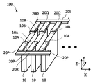
- FIG. 1 is a perspective view showing the configuration of the battery module according to the first embodiment of the present invention.
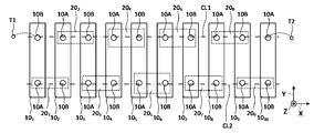
- FIG. 2 is a plan view of the battery module according to the first embodiment of the present invention.
- the battery module 100 according to the first embodiment includes a plurality of batteries 10 and a plurality of connecting members 20 for electrically connecting the batteries 10.
- the battery module 100 includes 10 batteries 10 and 9 connecting members 20 for connecting the 10 batteries 10 in series.
- the reference numerals “10 1 ”, “10 2 ”, ..., “10 10 ” are added to the plurality of batteries 10.
- the number of batteries 10 and the number of connecting members 20 are not particularly limited, and the battery module 100 may include 9 or less or 11 or more batteries 10, and 8 or less or 10 or more connecting members 20. May be provided.
- the number of connecting members 20 is determined by the number of batteries 10 and the connection form.
- Each battery 10 is a secondary battery such as a lithium ion secondary battery.
- each battery 10 may be a primary battery such as a lithium / manganese dioxide battery.
- Each battery 10 has a flat, substantially rectangular parallelepiped shape, and the dimension in the X direction is smaller than the dimension in the Y direction and the dimension in the Z direction.
- positive terminals 10A and negative terminals 10B are provided on the upper surface of each battery 10 so as to be arranged in the Y direction.
- each of the positive terminal 10A and the negative terminal 10B is also simply referred to as a terminal.
- each connecting member 20 is transparently shown by a dotted line.
- the plurality of batteries 10 are arranged so as to be arranged along the X direction.
- 10 pieces of batteries 10 1, 10 2, ..., 10 10 are arranged along the X direction in this order.
- the orientation of the plurality of batteries 10 is adjusted so that the positional relationship between the positive terminal 10A and the negative terminal 10B is opposite to each other between the two adjacent batteries 10.
- the plurality of terminals form two terminal rows CL1 and CL2 along the X direction, and the positive terminals 10A and the negative terminals 10B alternate in each of the terminal rows CL1 and CL2. Line up in.
- Each connecting member 20 is a so-called bus bar and has a substantially rectangular parallelepiped shape extending in the X direction.
- Each connecting member 20 is made of a conductive material such as metal, and in the present embodiment, a plurality of connecting members 20 are made of the same material.
- One end and the other end of each connection member 20 are attached to a pair of terminals adjacent to each other and having different polarities in each of the terminal rows CL1 and CL2.
- one end of each connecting member 20 is attached to the positive terminal 10A of one of the two batteries 10 adjacent to each other, and the other end of each connecting member 20 is the other battery 10. It is attached to the negative terminal 10B.
- the connecting member 20 1 is attached to the positive terminal 10A and the battery 10 and second negative terminal 10B of the battery 10 1, connected to the negative terminal 10B of the positive terminal 10A and the battery 10 3 of the battery 10 2 member 20 2 is attached, the connecting member 20 3 is attached to the negative terminal 10B of the positive terminal 10A and the battery 10 of the battery 10 3.
- the connecting member 20 N is attached to the positive terminal 10A of the battery 10 N (N is an integer of 1 or more and 9 or less) and the negative terminal 10B of the battery 10 N + 1 .
- the lowest potential terminal of the plurality of battery 10 terminals is connected to the external connection terminal T1, and the highest potential terminal of the plurality of battery 10 terminals is connected to the external connection terminal T2.
- the negative terminal 10B of the battery 10 1 is connected to the external connection terminal T1
- the positive terminal 10A of the battery 10 10 is connected to the external connection terminal T2.
- An external circuit such as a DC / DC converter is connected to the external connection terminals T1 and T2.
- the battery module 100 is charged and discharged through the external connection terminals T1 and T2.
- a pair of batteries 10 located at both ends in the arrangement direction (X direction) will be referred to as an end battery 10, and a pair of connecting members 20 attached to the pair of end batteries 10 respectively. It is referred to as an end connecting member 20.
- the battery 10 located in the central portion in the arrangement direction (X direction) is referred to as the central portion battery 10
- the connecting member 20 attached to the central portion battery 10 is referred to as the central portion connecting member 20. ..
- each of the batteries 10 1 and 10 10 corresponds to the end battery 10
- each of the batteries 10 5 and 10 6 corresponds to the central battery 10.
- the connection members 20 1, 20 9 corresponds to the end portion connecting member
- connecting member 20 5 corresponds to the central portion connecting member 20.
- each connecting member 20 The shape and dimensions of each connecting member 20 are set according to the position of each connecting member 20 in the battery module 100.
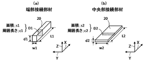
- FIG. 3 is a diagram for explaining the shape and dimensions of the connecting member 20.
- FIG. 3 (a) shows the end connecting member 20, and
- FIG. 3 (b) shows the central connecting member 20.
- the end connecting member 20 of FIG. 3A has a length L1, a thickness d1, a width w1, a cross-sectional area s1, and a peripheral length c1.
- the central portion connecting member 20 of FIG. 3B has a length L2, a thickness d2, a width w2, a cross-sectional area s2, and a peripheral length c2.
- the length of the connecting member 20 means the dimension of the connecting member 20 in the conductive direction.
- the connecting member 20 is attached to a pair of terminals adjacent to each other in the X direction, and a current flows between the pair of terminals, so that the X direction is regarded as the conductive direction.
- the thickness of the connecting member 20 means the dimension of the connecting member 20 in the Z direction
- the width of the connecting member 20 means the dimension of the connecting member 20 in the Y direction.
- the cross-sectional area of the connecting member 20 means the area of the cross section of the connecting member 20 perpendicular to the conductive direction (X direction). In the present embodiment, it is assumed that the cross-sectional area of the connecting member 20 is constant in the conductive direction.
- the area s1 of the cross section D1 perpendicular to the conductive direction (X direction) of the end connecting member 20 is represented by the product (d1 ⁇ w1) of the thickness d1 and the width w1 and is represented by the central connecting member 20.
- the area s2 of the cross section D2 perpendicular to the conductive direction (X direction) is represented by the product (d2 ⁇ w2) of the thickness d2 and the width w2.
- the cross section D1 is an example of the first cross section in the claim, and the cross section D2 is an example of the second cross section in the claim.
- the cross-sectional area of the connecting member 20 is not constant in the conductive direction, the average value of the cross-sectional area of the connecting member 20 in the conductive direction may be regarded as the cross-sectional area of the connecting member 20.
- the peripheral length of the connecting member 20 means the peripheral length of the cross section of the connecting member 20 perpendicular to the conductive direction (X direction). In the present embodiment, it is assumed that the peripheral length of the connecting member 20 is constant in the conductive direction. In this case, the peripheral length c1 of the cross section D1 of the end connecting member 20 is represented by the following formula (1), and the peripheral length c2 of the cross section D2 of the central connecting member 20 is represented by the following formula (2). To.
- the average value of the peripheral length of the connecting member 20 may be regarded as the peripheral length of the connecting member 20.
- the peripheral length c1 of the end connecting member 20 is set smaller than the peripheral length c2 of the central connecting member 20. Further, the cross-sectional area s2 of the central portion connecting member 20 is set to be equal to the cross-sectional area s1 of the end connecting member 20. Specifically, the thickness d1 of the end connecting member 20 is set to be larger than the thickness d2 of the central connecting member 20, and the width w1 of the end connecting member 20 is smaller than the width w2 of the central connecting member 20. Set. The length L1 of the end connecting member 20 is set to be equal to the length L2 of the central connecting member 20.
- “equal” is not limited to the case where they are exactly the same, but also includes the case where they are slightly different within the range in which the same action is exerted.
- each of the connecting members 20 located between the end connecting member 20 and the central connecting member 20 is larger than the end connecting member 20 and is larger than the end connecting member 20. It has a peripheral length smaller than that of the central connecting member 20. Further, the peripheral lengths of the plurality of connecting members 20 are set so as to increase in order from the end connecting member 20 to the central connecting member 20. Specifically, the connecting member 20 1, the connecting member 20 2, the connecting member 20 3, connecting members 20 4, perimeter is set larger in the order of the connection member 20 5, connecting members 20 9, connecting member 20 8, connected member 20 7, the connecting member 20 6, perimeter is set larger in the order of the connection member 20 5.
- each intermediate connecting member 20 is set to be equal to the cross-sectional area of the end connecting member 20 and the cross-sectional area of the central connecting member 20.
- each battery 10 depends on the position of each battery 10 in the battery module 100.
- the end batteries 10 (batteries 10 1 , 10 10 ) are likely to come into contact with the outside air because the other batteries 10 are not arranged on one side or the other side in the X direction. Therefore, it is easy to dissipate heat by heat transfer, heat conduction, radiation, or the like.
- the central battery 10 (batteries 10 5 and 10 6 ) has other batteries 10 arranged on both sides in the X direction, so that it is difficult to come into contact with the outside air. Therefore, unlike the end battery 10, it is difficult to dissipate heat. Since the heat dissipation of the central battery 10 is lower than the heat dissipation of the end battery 10, the temperature of the central battery 10 tends to be higher than the temperature of the end battery 10.
- an intermediate battery 10 between the end battery 10 and the central battery 10
- the internal resistance of the battery 10 depends on the temperature. Specifically, the lower the temperature of the battery 10, the greater the internal resistance of the battery 10. Therefore, if the temperatures of the plurality of batteries 10 vary, the internal resistance of the plurality of batteries 10 also varies. In particular, in a low temperature environment (for example, 10 degrees or less), if there is a temperature variation among the plurality of batteries 10, the variation in the internal resistance of the plurality of batteries 10 tends to be large.
- Variations in the internal resistance of the plurality of batteries 10 cause variations in the voltage between the terminals of the plurality of batteries 10.
- the voltage between terminals means the potential difference between the positive terminal 10A and the negative terminal 10B of each battery 10.
- the charge / discharge control of the battery module 100 is usually performed by using the voltage between the terminals of each battery 10. Therefore, if the voltage between the terminals of the plurality of batteries 10 varies, the charge / discharge control of the battery module 100 cannot be properly performed.
- the upper limit value and the lower limit value of the voltage between the terminals of each battery 10 are predetermined, and the battery module 100 so that the voltage between the terminals of all the batteries 10 falls within the range between the upper limit value and the lower limit value. Charging and discharging is controlled. In that case, when charging the battery module 100, if the terminal voltage of any one of the plurality of batteries 10 reaches the upper limit value, even if the terminal voltage of the other battery 10 does not reach the upper limit value. , The charging of the battery module 100 is stopped. Further, when the battery module 100 is discharged, if the terminal voltage of any one of the plurality of batteries 10 drops to the lower limit value, even if the terminal voltage of the other battery 10 does not drop to the lower limit value. , The discharge of the battery module 100 is stopped. In this case, charging / discharging of some of the batteries 10 is restricted more than necessary, so that the original input / output performance of the battery module 100 cannot be exhibited.
- the temperature variation among the plurality of batteries 10 also causes the variation in the degree of deterioration of the plurality of batteries 10. As described above, since various problems occur due to the temperature variation among the plurality of batteries 10, it is important for the battery module 100 to suppress the temperature variation among the plurality of batteries 10.
- a cooling flow path for providing a blower such as a fan and preferentially supplying cooling air from the cooling device to the battery 10 whose temperature tends to be high It is conceivable to provide. However, if a cooling device or a cooling flow path is provided, the battery module 100 becomes large and the cost increases.
- the Joule heat P generated in the conductor depends on the resistance R and the current I of the conductor, and becomes larger as the resistance R is larger and becomes larger as the current I is larger.
- the plurality of batteries 10 are connected in series via the plurality of connecting members 20, the currents flowing through the plurality of connecting members 20 are equal to each other.
- the resistance of the connecting member 20 is represented by the following equation (4).
- R is the resistance of the connecting member 20
- s is the cross-sectional area of the connecting member 20
- L is the length of the connecting member 20
- ⁇ is the electrical resistivity of the connecting member 20.
- the cross-sectional areas s of the plurality of connecting members 20 are equal to each other, and the lengths L of the plurality of connecting members 20 are equal to each other.
- the electrical resistivity ⁇ of the plurality of connecting members 20 is equal to each other. Since the cross-sectional area s, the length L, and the electrical resistivity ⁇ are equal to each other, the resistances R of the plurality of connecting members 20 are equal to each other. Therefore, as is clear from the above equation (3), the calorific value of the plurality of connecting members 20 is equal to each other.
- the connecting member 20 is affected by the skin effect.
- the skin effect is a phenomenon in which when an alternating current flows through a conductor, the current density of a portion close to the surface of the conductor (called the skin of the conductor) becomes higher than the current density inside the conductor. Therefore, even if the cross-sectional area of the conductor is the same, the larger the surface area of the conductor, the larger the proportion of the skin in the conductor, and the higher the current density of the conductor as a whole. As a result, the larger the surface area of the conductor, the smaller the resistance of the conductor as a whole.
- the peripheral length of the end connecting member 20 is smaller than the peripheral length of the central connecting member 20. Further, the length of the end connecting member 20 is equal to the length of the central connecting member 20. Therefore, the surface area of the end connecting member 20 is smaller than the surface area of the central connecting member 20. As a result, in the AC operation state, the resistance of the end connecting member 20 is larger than the resistance of the central connecting member 20. Therefore, according to the above equation (3), the amount of heat generated by the end connecting member 20 is larger than the amount of heat generated by the central connecting member 20. Further, since the surface area of the end connecting member 20 is larger than the surface area of the central connecting member 20, the heat dissipation of the central connecting member 20 is higher than that of the end connecting member 20.
- the temperature of each battery 10 changes as the heat generated by each connecting member 20 is transferred to each battery 10.
- the amount of heat generated by the end connecting member 20 is larger than the amount of heat generated by the central connecting member 20, and the heat dissipation of the central connecting member 20 is higher than that of the end connecting member 20.
- the amount of heat conduction from the connecting member 20 to the end battery 10 is larger than the amount of heat conduction from the central connecting member 20 to the central battery 10. Therefore, when the temperature of the central battery 10 is higher than the temperature of the end battery 10, the temperature of the end battery 10 approaches the temperature of the central battery 10.
- the peripheral length of the connecting member 20 increases in order from the end connecting member 20 to the central connecting member 20. Therefore, in the AC operation state, the amount of heat generated by the connecting member 20 increases in order from the central connecting member 20 to the end connecting member 20. As described above, with respect to the intermediate battery 10 between the central battery 10 and the end battery 10, the closer to the central battery 10, the higher the temperature of the battery 10 tends to be. Therefore, the temperature difference between the plurality of batteries 10 is reduced by increasing the amount of heat generated by the connecting member 20 in order from the central portion connecting member 20 to the end connecting member 20.
- the peripheral length of the connecting member 20 N and the peripheral length of the connecting member 20 10-N are equal to each other.
- the connection is preferably member 20 equal to the perimeter around the 2 length and connecting members 20 8, it is preferable that the perimeter of the connecting member 20 fourth perimeter and connecting member 20 6 equal to each other.
- the temperatures of the plurality of batteries 10 rise symmetrically between one side and the other side of the battery module 100 whose boundary is the central battery 10. As a result, temperature variation between one side and the other side of the battery module 100 is prevented.
- the cross-sectional areas of the plurality of connecting members 20 are equal to each other, the resistances of the plurality of connecting members 20 are equal to each other in the DC operating state, and the amount of heat generated differs between the plurality of connecting members 20. Does not occur.
- the battery module is in a DC operating state without causing temperature variation due to the difference in the amount of heat generated by the plurality of connecting members 20. 100 can be charged and discharged.
- the DC operating state and the AC operating state may be established at the same time. For example, when a DC current including a ripple component flows through the battery module 100, the battery module 100 is in a DC operating state and an AC operating state.
- the skin depth is an index showing the magnitude of the effect of the skin effect on a conductor. Inside the conductor, there is a portion where a current of 1 / e of the current flowing on the conductor surface flows, and the depth from the conductor surface to that portion is the skin depth. The smaller the skin depth, the greater the effect of the skin effect.
- the skin depth is expressed by the following equation (5).
- d is the skin depth
- ⁇ is the electrical resistivity of the conductor
- ⁇ is the angular frequency
- ⁇ is the absolute magnetic permeability of the conductor.
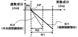
- FIG. 4 is a diagram showing the impedance characteristics of the end connecting member 20 and the central connecting member 20.
- the horizontal axis represents the real number component Zre of impedance
- the vertical axis represents the imaginary component Zim of impedance. The sign of the vertical axis is flipped up and down.
- each connecting member 20 can be measured based on the current response or voltage response when an AC voltage or AC current is applied to the connecting member 20.
- Impedance is represented by the real number component Zre and the imaginary number component Zim as in the following equation (6).
- the impedance of the end connecting member 20 is represented by the impedance Nyquist diagram IC1
- the impedance of the central connecting member 20 is represented by the impedance Nyquist diagram IC2.
- Impedance Nyquist diagrams IC1 and IC2 are drawn by measuring the impedance of the end connecting member 20 and the central connecting member 20 while changing the AC frequency, and sequentially plotting the real number component Zre and the imaginary number component Zim of the impedance. Can be done.
- Impedance in FIG. 4 Nyquist diagrams IC1 and IC2 represent changes in impedance of the end connecting member 20 and the center connecting member 20 in a certain frequency range.
- the imaginary component Zim of the impedance of each connecting member 20 depends on the AC frequency, and the imaginary component Zim increases as the AC frequency increases.
- the AC frequency becomes 0, and the imaginary component Zim of the impedance of the end connecting member 20 and the central connecting member 20 becomes 0.
- R0 the real number component Zre of the impedance of the end connecting member 20 and the central connecting member 20 when the imaginary number component Zim is 0 has a value R0 equal to each other. This means that the resistance of the end connecting member 20 and the resistance of the central connecting member 20 are equal in the DC operating state.
- the imaginary component Zim is larger than 0.
- the real number component Zre becomes larger than R0 due to the influence of the skin effect and the like. From FIG. 4, it can be seen that the larger the imaginary component Zim, the larger the real component Zre. This means that the higher the AC frequency, the higher the resistance.
- the larger the imaginary component Zim that is, the higher the AC frequency, the larger the difference between the real component Zre of the impedance of the end connecting member 20 and the real component Zre of the impedance of the central connecting member 20.
- the higher the AC frequency the larger the difference between the resistance of the end connecting member 20 and the resistance of the central connecting member 20.
- the larger the difference in resistance the larger the difference in heat generation. Therefore, the higher the AC frequency, the larger the difference between the heat generation amount in the end connection member 20 and the heat generation amount in the central connection member 20.
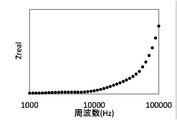
- FIG. 5 is a diagram showing the results of actual measurement of the relationship between the AC frequency and the real number component Zre of impedance in one connecting member 20.
- the horizontal axis represents the frequency and the vertical axis represents the real component Zre of impedance.
- the real number component of the impedance changes in the vicinity of 0.
- the real number component of impedance increases as the AC frequency increases.
- the AC frequency in the AC operating state Is preferably 10 kHz or higher.
- the calorific value Q of each connecting member 20 in the AC operating state is represented by the following equation (9).
- Zre is a real component of impedance.
- Irms is the root mean square of the maximum amplitude of the alternating current and represents the magnitude of the alternating current.
- the temperature rise width ⁇ T (K: Kelvin) of each connecting member 20 is represented by the following equation (11).
- Cv is the heat capacity (J / gK) of each connecting member
- M is the weight (g) of each connecting member 20. It is assumed that the amount of heat radiated from each connecting member 20 is 0.
- the thermal conductivity Qc (W: watt) from the connecting member 20 to the battery 10 is represented by the following formula (12). It is assumed that the temperature rise width ⁇ T is the temperature difference between the connecting member 20 and the battery 10. In the formula (12), D is the distance (m) between the connecting member 20 and the central portion of the battery 10, and K is the thermal conductivity (W / mK) of the battery 10.
- the energy U1 when an alternating current is passed through the battery module 100 for t seconds is represented by the following equation (13).
- the length L1 of the end connecting member 20 is 50 mm, the thickness d1 is 4 mm, the width w1 is 10 mm, the cross-sectional area s1 is 40 mm 2 , and the peripheral length c1 is 28 mm.
- the length L2 of the central portion connecting member 20 is 50 mm, the thickness d2 is 2 mm, the width w2 is 20 mm, the cross-sectional area s2 is 40 mm 2 , and the peripheral length c2 is 44 mm.
- each connecting member 20 is made of copper (Cu).
- the heat capacity Cv of copper is 0.38.
- the weights M of the end connecting member 20 and the central connecting member 20 are equal to each other and weigh 17.92 g.
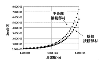
- FIG. 6 is a diagram showing the impedance characteristics of the end connecting member 20 and the central connecting member 20 having the above numerical values.
- the horizontal axis represents the frequency and the vertical axis represents the real component of the impedance.
- the real number component Zre of the impedance of the end connecting member 20 is 7.4 ⁇ 10 -3 ( ⁇ )
- Zre is 5.6 ⁇ 10 -3 ( ⁇ ).
- the temperature rise width ⁇ T when an alternating current is passed through the end connecting member 20 and the central connecting member 20 for 60 seconds is obtained. It is assumed that the maximum amplitude of the alternating current is 50A. In this case, the alternating current Irms is 35.4 A.
- the AC frequency is 100 kHz.
- the temperature rise width ⁇ T is calculated based on the equations (9) to (11)
- the temperature rise width ⁇ T of the end connecting member 20 is 5.2K
- the temperature rise width ⁇ T of the central connecting member 20 is It is 3.9K. That is, it can be seen that in the AC operation state, the temperature rise width of the end connecting member 20 is larger than the temperature rise width of the central connecting member 20.
- the peripheral length of each end connecting member 20 is smaller than the peripheral length of the central connecting member 20, so that the AC operating state Then, the amount of heat generated by each end connecting member 20 is larger than the amount of heat generated by the central connecting member 20. Therefore, even if the temperature of the central battery 10 becomes higher than the temperature of each end battery 10 due to the difference in heat dissipation, the heat conduction between the end connecting member 20 and the end battery 10 and the center The temperature difference between each end battery 10 and the central battery 10 can be reduced by heat conduction between the part connecting member 20 and the central battery 10.
- the temperature difference between each end battery 10 and the central battery 10 can be reduced only by the difference in the shape and dimensions of the connecting member 20 without providing a cooling device, a cooling flow path, or the like.
- the temperature of the intermediate battery 10 tends to converge between the temperature of the end battery 10 and the temperature of the central battery 10 due to the influence of the temperatures of the end battery 10 and the central battery 10. Therefore, the temperature difference between each end battery 10 and the central battery 10 becomes small, so that the temperature variation of the entire battery module 100 is suppressed. As a result, it is possible to suppress the temperature variation among the plurality of batteries 10 while suppressing the increase in size of the battery module 100.
- each end connecting member 20 and the cross-sectional area of the central connecting member 20 are equal to each other, in the DC operating state, each end connecting member 20 and the central connecting member 20 There is no difference in calorific value between them.
- the battery module 100 is charged and discharged without causing temperature variation due to the difference in the amount of heat generated by the plurality of connecting members 20. Can be made to.
- the temperature variation among the plurality of batteries 10 is suppressed by increasing the temperature of each battery 10, so that the average temperature of the plurality of batteries 10 increases.
- the internal resistance of the battery 10 decreases as the temperature increases. Therefore, as the average temperature of the plurality of batteries 10 rises, the resistance of the entire battery module 100 decreases. As a result, the input / output performance of the battery module 100 is improved.
- the peripheral length of the connecting member 20 increases in order from each end connecting member 20 to the central connecting member 20, so that the central connecting member 20 to each end connecting member 20 is in the AC operation state.
- the calorific value increases in order from 20.
- each connecting member 20 has a substantially rectangular parallelepiped shape, but the shape of the connecting member 20 is not limited to this.
- a modified example of the connecting member 20 will be described.
- FIG. 7 is a diagram for explaining a modification 1 of the connecting member 20.
- the connection member according to the first modification will be described focusing on the points different from the connection member 20 of FIG.
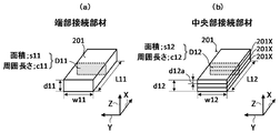
- FIG. 7 (a) shows the end connecting member 201 according to the first modification
- FIG. 7 (b) shows the central connecting member 201 according to the first modification.
- the end connecting member 201 of FIG. 7A has a substantially rectangular parallelepiped shape like the end connecting member 20 of FIG. 3A, and has a length L11, a thickness d11, a width w11, a cross-sectional area s11, and a periphery. It has a length c11.
- the cross-sectional area s11 and the peripheral length c11 are the area and the peripheral length of the cross section D11 perpendicular to the conductive direction (X direction). Section D11 is an example of the first section in the claims.
- the central connecting member 201 of FIG. 7B has a length L12, a thickness d12, a width w12, a cross-sectional area s12, and a peripheral length c12.
- the cross-sectional area s12 and the peripheral length c12 are the area and the peripheral length of the cross section D12 perpendicular to the conductive direction (X direction).
- Section D12 is an example of a second section in the claims.
- the length L12, thickness d12, width w12, and cross-sectional area s12 of the central portion connecting member 201 are equal to the length L11, thickness d11, width w11, and cross-sectional area s11 of the end connecting member 201, respectively.
- the central portion connecting member 201 is divided into a plurality of partial connecting members 201X (three in the example of FIG. 7B) in the Z direction, and the total value of the thickness d12a of the plurality of partial connecting members 201X is the thickness. Is equal to d12.
- Each partial connecting member 201X has a partial cross section perpendicular to the conductive direction (X direction), and a plurality of partial cross sections of the plurality of partial connecting members 201X constitute a cross section D12 of the central connecting member 201.
- the cross-sectional area s12 is the total area of the partial cross sections of the plurality of partial connecting members 201X
- the peripheral length c12 is the total peripheral length of the partial cross sections of the plurality of partial connecting members 201X.
- the partial cross section of the partial connecting member 201X is an example of the third cross section in the claim.
- the cross-sectional area s11 of the end connecting member 201 is equal to the cross-sectional area s12 of the central connecting member 201, while the peripheral length c11 of the end connecting member 201 is larger than the peripheral length c12 of the central connecting member 201. small.
- the peripheral length c11 of the end connecting member 201 is smaller than the peripheral length c12 of the central connecting member 201, the resistance of the end connecting member 201 is reduced by the influence of the skin effect in the AC operation state. It is larger than the resistance of 201. Therefore, the amount of heat generated by the end connecting member 201 is larger than the amount of heat generated by the central connecting member 201. As a result, even if the temperature of the central battery 10 becomes higher than the temperature of the end battery 10, the temperature difference between the end battery 10 and the central battery 10 is obtained by setting the battery module 100 in the AC operation state. Can be reduced.
- the resistance of the end connecting member 201 and the resistance of the central connecting member 201 are reduced in the DC operating state. Become equal. Therefore, the calorific value of the end connecting member 201 and the calorific value of the central connecting member 201 are equal to each other. Therefore, when there is no temperature variation between the plurality of batteries 10, or when the temperature variation is small, the battery module 100 is charged and discharged without causing temperature variation due to the difference in the amount of heat generated by the plurality of connecting members 201. be able to.
- the intermediate connecting member 201 between the central connecting member 201 and the end connecting member 201 has the same cross-sectional area as the end connecting member 201 and the central connecting member 201, and is larger than the end connecting member 201 and is central. It may be divided into a plurality of partial connecting members so as to have a peripheral length smaller than that of the partial connecting member 201. In this case, the number of partial connecting members constituting the intermediate connecting member 201 is set to be smaller than the number of partial connecting members constituting the central connecting member 201. Further, it is preferable that the number of partial connecting members constituting each intermediate connecting member 201 is adjusted so that the peripheral length of the connecting member 201 increases in order from the end connecting member 201 to the central connecting member 201. As a result, temperature variation among the plurality of batteries 10 can be efficiently suppressed.
- the end connecting member 201 of FIG. 7A is not divided into a plurality of partial connecting members, the end connecting member 201 may also be divided into a plurality of partial connecting members. In this case, the number of partial connecting members constituting the end connecting member 201 is set to be smaller than the number of partial connecting members constituting the central connecting member 201.
- FIG. 8 is a diagram for explaining a modification 2 of the connecting member 20.
- the connection member according to the second modification will be described focusing on the difference from the connection member 201 according to the first modification.
- FIG. 8 shows the central portion connecting member 202 according to the second modification.
- the end connecting member 202 according to the second modification has the same shape and dimensions as the end connecting member 201 according to the first modification.
- the central portion connecting member 202 of FIG. 8 has a length L13, a thickness d13, a width w13, a cross-sectional area s13, and a peripheral length c13.
- the cross-sectional area s13 and the peripheral length c13 are the area and the peripheral length of the cross section D13 perpendicular to the conductive direction (X direction).
- Section D13 is an example of the second section in the claims.
- the length L13, thickness d13, width w13, and cross-sectional area s13 of the central portion connecting member 202 are equal to the length, thickness, width, and cross-sectional area of the end connecting member 202, respectively.
- the central portion connecting member 202 is divided into a plurality of (five in the example of FIG. 8) partial connecting members 202X in the Y direction, and the total value of the widths w13a of the plurality of partial connecting members 202X is the central portion connecting member 202. Is equal to the width w13 of.
- Each partial connecting member 202X has a partial cross section perpendicular to the conductive direction (X direction), and a plurality of partial cross sections of the plurality of partial connecting members 202X constitute a cross section D13 of the central connecting member 202.
- the cross-sectional area s13 is the total area of the partial cross sections of the plurality of partial connecting members 202X, and the peripheral length c13 is the total peripheral length of the partial cross sections of the plurality of partial connecting members 202X.
- the partial cross section of the partial connecting member 202X is an example of the third cross section in the claim.
- the cross-sectional area s13 of the central portion connecting member 202 is equal to the cross-sectional area of the end connecting member 202, while the peripheral length c13 of the central portion connecting member 202 is larger than the peripheral length of the end connecting member 202.
- the temperature difference between the end battery 10 and the center battery 10 can be reduced in the AC operation state. Further, in the DC operating state, the battery module 100 can be charged and discharged without causing temperature variation due to the difference in the amount of heat generated by the plurality of connecting members 202.
- FIG. 9 is a diagram for explaining a modification 3 of the connecting member 20.
- the connection member according to the modification 3 will be described focusing on the difference from the connection member 201 according to the modification 1.
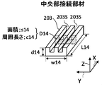
- FIG. 9 shows the central portion connecting member 203 according to the third modification.
- the end connecting member 203 according to the third modification has the same shape and dimensions as the end connecting member 201 according to the first modification.
- the central portion connecting member 203 of FIG. 9 has a length L14, a thickness d14, a width w14, a cross-sectional area s14, and a peripheral length c14.
- the cross-sectional area s14 and the peripheral length c14 are the area and the peripheral length of the cross section D14 perpendicular to the conductive direction (X direction).
- Section D14 is an example of the second section in the claims.
- the length L14, thickness d14, width w14, and cross-sectional area s14 of the central portion connecting member 201 are equal to the length, thickness, width, and cross-sectional area of the end connecting member 203, respectively.
- the central portion connecting member 203 is formed with one or a plurality of slits (groove portions) 203S extending in the conductive direction (X direction) instead of being divided into a plurality of partial connecting members.
- two slits 203S extending in the conductive direction (X direction) are formed on the upper surface of the central portion connecting member 203.
- the slit 203S may be formed so as to intersect the conductive direction diagonally.
- the cross-sectional area s14 of the central portion connecting member 203 is set to be equal to the cross-sectional area of the end connecting member 203.
- the peripheral length of the central portion connecting member 203 is larger than the peripheral length of the end connecting member 203 due to the formation of the slit 203S.
- the temperature difference between the end battery 10 and the center battery 10 can be reduced in the AC operation state. Further, in the DC operating state, the battery module 100 can be charged and discharged without causing temperature variation due to the difference in the amount of heat generated by the plurality of connecting members 202.
- FIG. 10 is a diagram for explaining a modification 4 of the connecting member 20.
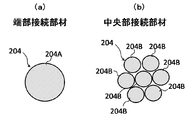
- FIG. 10A shows a cross section of the end connecting member 204 according to the modified example 4
- FIG. 10B shows a cross section of the central connecting member 204 according to the modified example 4.
- the end connecting member 204 in FIG. 10A is composed of one wiring member 204A.
- the central portion connecting member 204 of FIG. 10B includes a plurality of wiring members 204B.
- the total cross-sectional area of the plurality of wiring members 204B is equal to the cross-sectional area of the wiring members 204A.
- the total value of the peripheral lengths of the plurality of wiring members 204B is larger than the peripheral lengths of the plurality of wiring members 204A. That is, the cross-sectional area of the central portion connecting member 204 is equal to the cross-sectional area of the end connecting member 204, while the peripheral length of the central portion connecting member 204 is larger than the peripheral length of the end connecting member 204.
- the wiring member 204B is an example of the partial connection member in the claim, and the cross section of the wiring member 204B is an example of the third cross section in the claim.
- the temperature difference between the end battery 10 and the center battery 10 can be reduced in the AC operation state. Further, in the DC operating state, the battery module 100 can be charged and discharged without causing temperature variation due to the difference in the amount of heat generated by the plurality of connecting members 204.
- the cross-sectional area of the end connecting member and the cross-sectional area of the central connecting member are set to be equal to each other, but the cross-sectional area of the end connecting member and the cross-sectional area of the central connecting member are set to be equal. They may be different from each other.
- the shape of the connecting member is not limited to the above example, and may have various other shapes.
- the connecting member may have a cylindrical shape, a cylindrical shape, or a triangular prism shape.
- FIG. 11 is a diagram showing an example of a battery module 100 in which a plurality of batteries 10 are connected in parallel. The battery module 100 of FIG. 11 will be described focusing on the differences from the battery module 100 of FIGS. 1 and 2.
- the battery module 100 of FIG. 11 the positional relationship between the positive terminals 10A and the negative terminals 10B of the plurality of batteries 10 is equal to each other. Further, the battery module 100 of FIG. 11 includes a plurality of connecting members 20P, a plurality of connecting members 20Q, one connecting member 20R, and one connecting member 20S instead of the plurality of connecting members 20.
- Each of the connecting members 20P and 20Q has a substantially rectangular parallelepiped shape extending in the Y direction
- each of the connecting members 20R and 20S has a substantially rectangular parallelepiped shape extending in the X direction.
- One end of a plurality of connecting members 20P is attached to each of the positive terminals 10A of the plurality of batteries 10.
- One ends of the plurality of connecting members 20Q are attached to the negative terminals 10B of the plurality of batteries 10.
- the other ends of the plurality of connecting members 20P are connected to the connecting member 20R, and the other ends of the plurality of connecting members 20Q are attached to the connecting member 20S.
- a plurality of batteries 10 are mounted in parallel.
- the connecting member 20S is connected to the external connection terminal T1 of FIG. 1, and the connecting member 20R is connected to the external connection terminal T2 of FIG.
- the peripheral length of the central connecting member 20P attached to the central battery 10 is set to be larger than the peripheral length of the end connecting member 20P attached to the end battery 10, and is attached to the central battery 10.
- the peripheral length of the central portion connecting member 20Q is set to be larger than the peripheral length of the end connecting member 20P attached to the end battery 10.
- the cross-sectional area of the central portion connecting member 20P attached to the central portion battery 10 may be set to be equal to the cross-sectional area of the end portion connecting member 20P attached to the end portion battery 10
- the center attached to the central portion battery 10 may be set to be equal to the cross-sectional area.
- the cross-sectional area of the part connecting member 20Q may be set equal to the cross-sectional area of the end connecting member 20Q attached to the end battery 10.
- the Y direction can be regarded as the conductive direction in the connecting members 20P and 20Q
- the area of the cross section perpendicular to the Y direction corresponds to the cross-sectional area of the connecting members 20P and 20Q
- the peripheral length of the cross section Corresponds to the peripheral length of the connecting members 20P and 20Q.
- the temperature difference between the end battery 10 and the central battery 10 can be reduced in the AC operating state.
- the cross-sectional areas of the plurality of connecting members 20P are equal to each other and the cross-sectional areas of the plurality of connecting members 20Q are set to be equal to each other, it is caused by the difference in the amount of heat generated by the plurality of connecting members 201 in the DC operating state.
- the battery module 100 can be charged and discharged without causing temperature variation.
- connecting members 20P and 20Q other connecting members having various shapes may be used as in the examples of FIGS. 7 to 10.
- FIG. 12 is a diagram showing the relationship between the SOC (charged state) of the battery 10 using lithium iron phosphate as the positive electrode material and the OCV (Open Circuit Voltage: open circuit voltage).
- the horizontal axis represents SOC and the vertical axis represents OCV.
- the relationship between SOC and OCV is the same as the relationship shown in FIG.
- the variation in internal resistance among the plurality of batteries 10 is suppressed by suppressing the temperature variation among the plurality of batteries 10. If the variation in the internal resistance is small, the plurality of batteries 10 are charged and discharged substantially evenly, so that the variation in SOC is unlikely to occur. Therefore, in the above embodiment, even when an iron-based material such as lithium iron phosphate or lithium titanate is used as the material of the battery 10, overcharging or overdischarging does not occur and the battery 10 is appropriately used. Charging and discharging can be controlled.
- the thermal conductivity between the connecting member 20 and the battery 10 may be adjusted by adjusting the contact area between the connecting member 20 and the battery 10. Specifically, the larger the contact area between the connecting member 20 and the battery 10, the easier it is for the heat generated by the connecting member 20 to be transferred to the battery 10. Therefore, by adjusting the contact area between the connecting member 20 and the battery 10, it is possible to more efficiently suppress the temperature variation among the plurality of batteries 10. For example, when the temperature difference between the end battery 10 and the central battery 10 tends to be large, the contact area between the end connecting member 20 and the end battery 10 is the contact area between the central connecting member 20 and the central battery 10. Set larger than the area.
- the amount of heat generated by the end connecting member 20 is larger than that of the central connecting member 20, and heat is more easily transferred to the end battery 10 than that of the central battery 10. Thereby, the temperature difference between the end battery 10 and the center battery 10 can be reduced more effectively.
- the plurality of batteries 10 are arranged in a row along one direction (X direction), but the arrangement of the plurality of batteries 10 is not limited to this.
- a plurality of batteries 10 may be arranged so as to form a plurality of rows. Further, a plurality of batteries 10 may be arranged so as to be arranged along a curve. Alternatively, the plurality of batteries 10 may not be arranged in the horizontal direction, but the plurality of batteries 10 may be stacked in the vertical direction (Z direction).
- the peripheral length of the connecting member 20 attached to the battery 10 located at the end in the arrangement direction of the plurality of batteries 10 is the connection attached to the battery located at the center in the arrangement direction of the plurality of batteries 10. It is set to be larger than the peripheral length of the member 20. Thereby, in the AC operation state, the temperature difference between the end battery 10 and the center battery 10 can be reduced. Further, by setting the cross-sectional areas of the plurality of connecting members 20 to be equal to each other, the battery module 100 is filled in the DC operating state without causing temperature variation due to the difference in the amount of heat generated by the plurality of connecting members 201. It can be discharged.
- the cross-sectional area of the end connecting member 20 and the cross-sectional area of the central connecting member 20 are set to be equal to each other, but the present invention is not limited to this, and the end connecting member 20 The cross-sectional area and the cross-sectional area of the central connecting member 20 may be different from each other. However, in order to suppress the difference in the amount of heat generated between the plurality of connecting members 20 in the DC operating state, the ratio of the cross-sectional area of the central portion connecting member 20 to the cross-sectional area of the end connecting member 20 is set to the end connecting member 20.
- the end connecting member 20 and the cross-sectional area of the central connecting member 20 are set different values, temperature variation among the plurality of batteries 10 is suppressed not only in the AC operating state but also in the DC operating state. It is possible to make it.
- the end connection member The cross-sectional area of 20 is set smaller than the cross-sectional area of the central connecting member 20. As described above, in the DC operating state, the smaller the cross-sectional area of the connecting member 20, the larger the resistance of the connecting member 20.
- the amount of heat generated by the end connecting member 20 is larger than the amount of heat generated by the end connecting member 20 even in the DC operating state. Will also grow. As a result, when the temperature of the central battery 10 becomes higher than the temperature of the end battery 10, the temperature of the end battery 10 can be brought close to the temperature of the central battery 10 even in the DC operating state.
- the cross-sectional area of the intermediate connecting member 20 may be appropriately adjusted according to the heat dissipation of each battery 10.
- (E) It is also possible to selectively raise the temperature of the desired battery 10 by changing the mounting positions of the plurality of connecting members 20 having different peripheral lengths. For example, when the degree of deterioration of a plurality of batteries 10 varies due to factors such as individual differences, a connection member 20 that easily generates heat is attached to the battery 10 having a low degree of deterioration, and the battery 10 having a high degree of deterioration does not easily generate heat. Attach the connecting member 20. In this case, the battery 10 having a low degree of deterioration is accelerated in deterioration by increasing the temperature, and the battery 10 having a high degree of deterioration is suppressed in deterioration by suppressing the increase in temperature. Thereby, it is possible to reduce the variation in the degree of deterioration among the plurality of batteries 10.
- the peripheral length of the connecting member 20 increases in order from the end connecting member 20 to the central connecting member 20, but the present invention is not limited to this.
- the temperature of the intermediate battery 10 tends to converge between the temperature of the end battery 10 and the temperature of the central battery 10. Therefore, the shape and dimensions of the intermediate connecting member 20 may be appropriately changed as long as the amount of heat generated by the intermediate connecting member 20 does not become excessive.
- the end battery 10 (batteries 10 1 , 10 10 ) and the external connection terminals T1 and T2 may be electrically connected via the connection member 20, respectively.
- the connecting member 20 that connects the end battery 10 and the external connection terminals T1 and T2 may be regarded as the end connecting member 20.
- each battery 10 has a flat substantially rectangular parallelepiped shape, but the shape of the battery 10 can be changed as appropriate.
- a battery 10 having a cylindrical shape may be used, or a battery 10 having a button shape may be used.
- a plurality of batteries 10 having different shapes may be used in combination.
- the number of batteries 10 and connecting members 20 can be changed as appropriate.
- the number of connecting members 20 is preferably 3 or more, including two end connecting members 20 located at both ends and one central connecting member 20.
- the number of batteries 10 is preferably 4 or more, and the plurality of batteries 10 as in the example of FIG.
- the number of batteries 10 is preferably 3 or more.
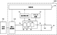
- FIG. 13 is a diagram showing the configuration of the battery module system according to the second embodiment.
- the battery module system 150 according to the second embodiment in addition to the battery module 100 according to the first embodiment, the power conversion unit 51, the temperature detection unit 52, the balance circuit 53, and the AC generation unit 55 , Switches 56A, 56B and a control unit 60.
- the battery module 100 the battery module 100 according to the above various modifications may be used.
- the power conversion unit 51 has a pair of input terminals and an output terminal. One input terminal of the power conversion unit 51 is connected to the external connection terminal T1 of the battery module 100 via the switch 56A, and the other input terminal is connected to the external connection terminal T2 of the battery module 100.
- the output terminal of the power conversion unit 51 is connected to a DC load 70 as an external load.
- the DC load 70 is, for example, an electric device such as a lighting device or a temperature control device.
- the switch 56A When the switch 56A is turned on, the battery module 100 and the power conversion unit 51 are electrically connected, and when the switch 56A is turned off, the battery module 100 and the power conversion unit 51 are electrically disconnected.
- the switch 56A may be provided between the other input terminal of the power conversion unit 51 and the external connection terminal T2 of the battery module 100, and the pair of input terminals of the power conversion unit 51 and the external connection terminal T1 of the battery module 100. , T2 may be provided respectively.
- the switch 56A is an example of the second switch in the claim.
- the power conversion unit 51 includes a DC / DC converter, converts the voltage of the DC power output from the battery module 100 into a value suitable for the DC load 70 in a state where the switch 56A is turned on, and converts the converted DC power. Is given to the DC load 70.
- the temperature detection unit 52 detects the temperature distribution among the plurality of batteries 10 of the battery module 100, and gives the detected temperature distribution to the control unit 60 as temperature distribution information.
- the temperature detection unit 52 includes a plurality of temperature sensors corresponding to the plurality of batteries 10.
- the plurality of temperature sensors each detect the temperatures of the plurality of batteries 10, and the detection results are given to the control unit 60 as temperature distribution information.
- the temperature detection unit 52 may include infrared thermography, and the infrared thermography may generate thermal image data representing the temperature distribution of the plurality of batteries 10 and give the thermal image data to the control unit 60 as temperature distribution information. ..
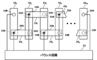
- the balance circuit 53 detects the voltage between the terminals of each battery 10, and based on the detection result, performs a balancing operation for suppressing the variation in the voltage between the terminals among the plurality of batteries 10.
- the balance circuit 53 may balance the inter-terminal voltages of a plurality of batteries 10 by discharging the batteries 10 having a relatively high inter-terminal voltage (passive type), or the inter-terminal voltage is relatively high.
- the inter-terminal voltage of a plurality of batteries 10 may be balanced by regenerating power from the battery 10 having the above to the battery 10 having a relatively low inter-terminal voltage (active type). The relationship between the balance circuit 53 and each battery 10 of the battery module 100 will be described later.
- the AC generation unit 55 includes a DC power supply 551 and a power conversion unit 552 to generate AC power.
- the power conversion unit 552 has a pair of input terminals and a pair of output terminals.
- the positive electrode terminal and the negative electrode terminal of the DC power supply 551 are connected to a pair of input terminals of the power conversion unit 552, respectively.
- One output terminal of the power conversion unit 552 is connected to the external connection terminal T2 of the battery module 100 via the switch 56B, and the other output terminal is connected to the external connection terminal T1 of the battery module 100.
- the switch 56B When the switch 56B is turned on, the battery module 100 and the power conversion unit 552 are electrically connected, and when the switch 56B is turned off, the battery module 100 and the power conversion unit 552 are electrically disconnected.
- the switch 56B may be provided between one output terminal battery of the power conversion unit 51 and the external connection terminal T1 of the battery module 100, and the pair of output terminals of the power conversion unit 552 and the external connection terminal of the battery module 100. It may be provided between T1 and T2 respectively.
- the switch 56 is an example of the first switch in the claim.
- the power conversion unit 552 includes a DC / AC converter, converts DC power from the DC power supply 551 into AC power in a state where the switch 56B is turned on, and supplies the converted AC power to the battery module 100.
- the control unit 60 switches the switches 56A and 56B on and off based on the temperature distribution detected by the temperature detection unit 52. Specifically, the control unit 60 determines the presence or absence of temperature variation among the plurality of batteries 10 based on the temperature distribution detected by the temperature detection unit 52, and switches when there is a temperature variation among the plurality of batteries 10. The switch 56A is turned off and the switch 56B is turned on, and when there is no temperature variation among the plurality of batteries 10, the switch 56A is turned on and the switch 56B is turned off. Further, the control unit 60 controls the power conversion unit 51 so that the DC power is supplied from the battery module 100 to the DC load 70 with the switch 56A turned on and the switch 56B turned off. In this case, the battery module 100 is maintained in the DC operating state. Further, the control unit 60 controls the power conversion unit 552 so that the AC power is supplied from the AC generation unit 55 to the battery module 100 with the switch 56A turned off and the switch 56B turned on. In this case, the battery module 100 is maintained in the AC operating state.
- the function of the control unit 60 may be realized by hardware such as an electronic circuit or by software.
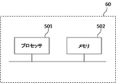
- FIG. 14 is a diagram showing an example in which at least a part of the functions of the control unit 60 are realized by software.
- the control unit 60 includes a processing device (processor) 501 and a storage device (memory) 502.
- the processing device 501 is, for example, a CPU (Central Processing Unit), and various control operations can be realized by reading and executing a program stored in the storage device 502.
- CPU Central Processing Unit
- FIG. 15 is a flowchart of the temperature variation suppression process.
- the switch 56A is turned on and the switch 56B is turned off.
- the control unit 60 operates the power conversion unit 51, while stopping the power conversion unit 552 of the AC generation unit 55.
- DC power is supplied from the battery module 100 to the DC load 70. That is, the battery module 100 is in a DC operating state.
- step S1 of FIG. 15 the control unit 60 determines whether or not there is a temperature variation among the plurality of batteries 10 based on the temperature detection information given from the temperature detection unit 52. For example, the control unit 60 determines whether or not the temperature difference between the central battery 10 and the end battery 10 exceeds a predetermined threshold value. When this temperature difference exceeds the threshold value, the control unit 60 determines that there is a temperature variation among the plurality of batteries 10, and when the temperature difference is equal to or less than the threshold value, the control unit 60 determines that there is a temperature variation between the plurality of batteries 10. Judge that there is no temperature variation.
- the method for determining the presence or absence of temperature variation is not limited to this.
- control unit 60 calculates an average value of the temperatures of the central battery 10 and the surrounding batteries 10 and an average value of the temperatures of the end battery 10 and the surrounding batteries 10, respectively, and calculates the average value of these average values.
- the presence or absence of temperature variation may be determined based on whether or not the difference exceeds a predetermined threshold.
- step S1 if there is no temperature variation among the plurality of batteries 10, the control unit 60 repeats step S1 while maintaining the battery module 100 in the DC operating state. Specifically, the control unit 60 keeps the switch 56A on and the switch 56B off to continue the operation of the power conversion unit 51.
- the cross-sectional areas of the plurality of connecting members 20 are set to be equal to each other. Therefore, in the DC operating state, there is no difference in the amount of heat generated between the plurality of connecting members 20. As a result, when there is no temperature variation between the plurality of batteries 10, electric power can be supplied from the battery module 100 to the DC load 70 while suppressing an increase in the temperature variation.
- step S1 If there is a temperature variation between the plurality of batteries 10 in step S1, the control unit 60 proceeds to step S2 and switches the battery module 100 from the DC operating state to the AC operating state. Specifically, the control unit 60 turns off the switch 56A and turns on the switch 56B. Further, the control unit 60 stops the operation of the power conversion unit 51 and starts the operation of the power conversion unit 552 of the AC generation unit 55.
- the peripheral length of the end connecting member 20 is smaller than the peripheral length of the central connecting member 20, the amount of heat generated by the end connecting member 20 is smaller in the AC operation state. It is larger than the amount of heat generated by the central connection member 20. Due to this difference in calorific value, the temperature difference between the end battery 10 and the center battery 10 can be reduced. As a result, temperature variation among a plurality of batteries can be suppressed.
- step S3 the control unit 60 determines whether or not there is a temperature variation among the plurality of batteries 10 in the same manner as in step S1.
- the control unit 60 repeats step S3 while maintaining the battery module 100 in an AC operating state until there is no temperature variation among the plurality of batteries 10. Specifically, the control unit 60 keeps the switch 56A off and the switch 56B on, and continues the operation of the power conversion unit 552.
- step S3 when the temperature variation among the plurality of batteries 10 disappears, the control unit 60 proceeds to step S4 and switches the battery module 100 from the AC operating state to the DC operating state. Specifically, the control unit 60 turns on the switch 56A and turns off the switch 56B. Further, the control unit 60 stops the operation of the power conversion unit 552 of the AC generation unit 55 and operates the power conversion unit 51. After that, the control unit 60 returns to step S1.
- the switches 56A and 56B are switched on and off based on the temperature distribution among the plurality of batteries 10 of the battery module 100. Specifically, when the temperature varies among the plurality of batteries 10, the battery module 100 is switched to the AC operating state. In the battery module 100, the temperature difference between each end battery 10 and the central battery 10 can be reduced by the difference in the amount of heat generated between each end connecting member 20 and the central connecting member 20, so that the battery It is possible to suppress temperature variation among a plurality of batteries 10 while suppressing an increase in the size of the module 100. On the other hand, when there is no temperature variation among the plurality of batteries 10, the battery module 100 is switched to the DC operating state.
- the battery module 100 since there is no difference in the amount of heat generated between the end connecting member 20 and the central connecting member 20, the battery module 100 does not cause temperature variation due to the difference in the amount of heat generated. Can supply power to the DC load 70. In this way, by appropriately switching the battery module 100 between the AC operating state and the DC operating state, it is possible to supply electric power to the DC load 70 while suppressing temperature variation among the plurality of batteries 10.
- the DC load 70 is connected to the battery module system 150 as an external load, but an AC load such as a motor may be connected instead of the DC load 70.
- a DC / AC converter is used as the power conversion unit 51 instead of the DC / DC converter.
- a power supply source such as a power system or a generator may be connected. In that case, the battery module 100 is charged by supplying electric power to the battery module 100 from the power supply source.
- one of the switches 56A and 56B is turned on and the other is turned off so that the battery module 100 is in either the DC operating state or the AC operating state, but the battery module 100 is DC.
- Both switches 56A and 56B may be turned on so as to be in the operating state and in the AC operating state.
- AC power is supplied from the AC generation unit 55 to the battery module 100
- DC power is supplied from the battery module 100 to the DC load 70 via the power conversion unit 51.
- the AC power from the AC generation unit 55 can continuously supply the DC power to the DC load 70 while suppressing the temperature variation among the plurality of batteries 10.
- the control unit 60 determines the frequency of the AC power generated by the AC generation unit 55 based on the temperature distribution detected by the temperature detection unit 52. You may adjust.
- the control unit 60 determines the degree of temperature variation among the plurality of batteries 10 based on the temperature detection information given from the temperature detection unit 52. Is calculated.
- the degree of temperature variation may be the temperature difference between the central battery 10 and the end battery 10, or the average value of the temperatures of the central battery 10 and the surrounding batteries 10 and the end battery 10 and It may be the difference from the average value of the temperatures of the surrounding batteries 10.
- the control unit 60 determines the AC frequency based on the degree of temperature variation. Specifically, the higher the degree of temperature variation, the higher the AC frequency is determined.
- the control unit 60 sets the power conversion unit 552 so that the AC power of the determined frequency is supplied to the battery module 100 from the AC generating unit 55. Control.
- the influence of the skin effect on each connecting member 20 depends on the AC frequency.
- the higher the AC frequency the greater the influence of the skin effect, and the greater the difference in the amount of heat generated between the end connecting member 20 and the central connecting member 20. Therefore, by adjusting the AC frequency based on the degree of temperature variation, it is possible to effectively suppress the temperature variation among the plurality of batteries 10.
- FIG. 16 is a diagram showing a connection example of the balance circuit 53 and the battery module 100.
- the balance circuit 53, the lowest potential terminal (battery 10 1 of the negative terminal 10B) and the highest potential terminal of the terminals of the battery 10 (positive terminal 10A of the battery 10 10) At the same time, they are connected to a specific position 20A of each connecting member 20.
- the position 20A is set so as to overlap the positive terminal 10A of the battery 10 in a plan view.
- the balance circuit 53 detects the voltage between the terminals of the plurality of batteries 10 based on the lowest potential terminal and the highest potential terminal among the terminals of the plurality of batteries 10 and the potentials of the positions 20A of the plurality of connecting members 20. However, if the detected voltage between terminals varies, a balanced operation is performed.
- the potential of the position 20A of each connecting member 20 can be regarded as equal to the potential of the positive terminal 10A of each battery 10. .. Further, when the cross-sectional areas of the plurality of connecting members 20 are equal to each other, the resistances of the plurality of connecting members 20 in the DC operating state are equal to each other. In this case, the potential difference between the positive terminal 10A and the negative terminal 10B electrically connected by each connecting member 20 is a constant value. Therefore, the potentials of the positive terminal 10A and the negative terminal 10B can be easily derived from the potential of the position 20A of each connecting member 20. Therefore, by detecting the potentials of the terminal having the lowest potential and the potential of the terminal having the highest potential in addition to the potentials at the positions 20A of the plurality of connecting members 20, the voltage between the terminals of all the batteries 10 can be detected.
- the cross-sectional areas of the plurality of connecting members 20 are different from each other, the resistances of the plurality of connecting members 20 are different from each other. Therefore, the potential difference between the positive terminal 10A and the negative terminal 10B electrically connected by each connecting member 20 differs depending on the connecting member 20. As a result, it is difficult to accurately derive the potentials of the positive terminal 10A and the negative terminal 10B from the potential of the position 20A of each connecting member 20, and a detection error of the voltage between terminals is likely to occur. Therefore, even if the voltage between the terminals of the plurality of batteries 10 actually varies, the balance operation may not be performed due to the detection error. Alternatively, even when there is almost no variation in the voltage between the terminals of the plurality of batteries 10, the balance operation may be performed due to the detection error, and as a result, the variation in the voltage between the terminals may become large. is there.
- the balance circuit 53 is only connected to one position 20A of each connecting member 20, and the voltage between terminals of each battery 10 is accurately adjusted. Can be detected. As a result, the balance circuit 53 can properly perform the balance operation while suppressing the increase in cost and the complexity of the configuration.
- the balance circuit 53 is connected to each connection member 20 at a position 20A that overlaps with the positive terminal 10A of the battery 10 in a plan view, but the connection position of the balance circuit 53 is limited to this. Not done.
- the balance circuit 53 may be connected at a position overlapping the negative terminal 10B of the battery 10 in a plan view. Further, if the relative positional relationship between the connection position and the positive terminal 10A and the relative positional relationship between the connection position and the negative terminal 10B are constant, the difference between the potential of the connection position and the potential of the positive terminal 10A. , And the difference between the potential at the connection position and the minus terminal 10B is constant regardless of the connection member 20.
- the potentials of the positive terminal 10A and the negative terminal 10B can be easily derived from the potential of the connection position. Therefore, it is also possible to connect the balance circuit 53 to each connecting member 20 at a position between the positive terminal 10A and the negative terminal 10B, or at a position outside the positive terminal 10A or the negative terminal 10B.
- FIG. 17 is a diagram showing a configuration of the battery module system 150A according to the third embodiment.
- the battery module system 150A includes a capacitor 65 and a switch 56C instead of the AC generator 55 and the switches 56A and 56B in FIG. Further, the battery module system 150A includes a power conversion unit 51A instead of the power conversion unit 51.
- the power conversion unit 51A has a pair of input terminals and an output terminal. One input terminal of the power conversion unit 51 is connected to the external connection terminal T1 of the battery module 100, and the other input terminal is connected to the external connection terminal T2 of the battery module 100.
- the output terminal of the power conversion unit 51A is connected to an AC load 70A as an external load.
- the AC load 70A is, for example, a motor.
- the power conversion unit 552 includes a DC / AC converter, converts the DC power output from the battery module 100 into AC power, and applies the converted AC power to the AC load 70A.
- One end of the capacitor 65 is connected to the external connection terminal T2 of the battery module 100 via the switch 56C, and the other end of the capacitor 65 is connected to the other input terminal of the power conversion unit 51A.
- the capacitor 65 is an example of the high frequency removing unit in the claim
- the switch 56C is an example of the third switch in the claim. When the switch 56C is turned on, the capacitor 65 is electrically connected to the battery module 100, and when the switch 56C is turned off, the capacitor 65 is electrically disconnected from the battery module 100.
- the control unit 60 switches the switch 56C on and off based on the temperature distribution detected by the temperature detection unit 52. Specifically, the control unit 60 determines the presence or absence of temperature variation among the plurality of batteries 10 based on the temperature distribution information from the temperature detection unit 52, and if there is no temperature variation among the plurality of batteries 10, the control unit 60 determines whether or not there is a temperature variation among the plurality of batteries 10. Turn on the switch 56C. In this case, the high frequency component is removed from the alternating current flowing through the battery module 100 by the capacitor 65. As described above, the higher the frequency of the alternating current flowing through the battery module 100, the larger the difference between the calorific value of the end connecting member 20 and the calorific value of the central connecting member 20.
- the larger the high frequency component flowing through the battery module 100 the larger the difference in the amount of heat generated between the plurality of connecting members 20. Therefore, by removing the high frequency component from the alternating current, the difference between the calorific value of the end connecting member 20 and the calorific value of the central connecting member 20 is reduced. As a result, an increase in temperature variation in the plurality of batteries 10 is suppressed.
- the control unit 60 turns off the switch 56C.
- the high frequency component is not removed from the alternating current flowing through the battery module 100.
- the difference between the calorific value of the end connecting member 20 and the calorific value of the central connecting member 20 becomes large, and the temperature of the end battery 10 approaches the temperature of the central battery 10.
- temperature variation among the plurality of batteries 10 can be suppressed.
- the capacitor 65 is used as the high frequency removing section, but another low-pass filter circuit may be used instead of the capacitor 65.
- a low-pass filter circuit including an operational amplifier may be used instead of the capacitor 65.
- a power supply source such as a power system or a generator may be connected.
- the AC power from the power supply source is converted into DC power by the power conversion unit 51A, and the converted DC power is supplied to the battery module 100.
- the battery module 100 is charged.
- the switch 56C is switched on and off based on the voltage distribution information from the temperature detection unit 52. Specifically, when there is no temperature variation among the plurality of batteries 10, the switch 56C is turned on. As a result, the high frequency component is removed from the alternating current flowing through the battery module 100 by the capacitor 65, and the increase in temperature variation in the plurality of batteries 10 is suppressed.
Landscapes
- Engineering & Computer Science (AREA)
- Electrochemistry (AREA)
- General Chemical & Material Sciences (AREA)
- Manufacturing & Machinery (AREA)
- Chemical & Material Sciences (AREA)
- Chemical Kinetics & Catalysis (AREA)
- Power Engineering (AREA)
- Secondary Cells (AREA)
- Electromagnetism (AREA)
- Physics & Mathematics (AREA)
- Battery Mounting, Suspending (AREA)
- Connection Of Batteries Or Terminals (AREA)
- Charge And Discharge Circuits For Batteries Or The Like (AREA)
Abstract
電池モジュール(100)は、複数の電池(10)と、複数の接続部材(20)とを含む。複数の電池(10)は、複数の接続部材(20)によって電気的に接続される。複数の接続部材(20)は、複数の電池(10)のうち両端部に位置する一対の端部電池にそれぞれ取り付けられる一対の端部接続部材と、複数の電池(10)のうち中央部に位置する中央部電池に取り付けられる中央部接続部材とを含む。各端部接続部材の導電方向に対して垂直な第1断面(D1)の周囲長さは、中央部接続部材の導電方向に対して垂直な第2断面(D2)の周囲長さよりも小さく設定される。
Description
この発明は、複数の電池を含む電池モジュール、およびその電池モジュールを備えた電池モジュールシステムに関する。
従来、電気自動車等の電力源として複数の電池を含む電池モジュールが用いられる。電池モジュールは、複数の電池がバスバー等の接続部材を介して直列または並列に接続された構成を有する。
接続部材の形状は、電池モジュールの種々の性能に影響する。例えば、特許文献1に記載されるバッテリモジュールにおいては、平面形状を有する複数のバスバーにより複数のセルが互いに電気的に接続されている。この場合、各バスバーの表面積が比較的大きくなるので、各セルの充放電によって発生される熱を各バスバーから効果的に放散させることが可能となる。また、表面積が大きいほど、表皮効果によって高周波のインピーダンスが小さくなるので、複数のセルの接続経路における電圧降下および発熱を抑制することが可能となる。
上記のような電池モジュールにおいては、複数の電池の放熱性の差に起因して、複数の電池間で温度ばらつきが生じることがある。例えば、電池モジュールの端部に位置する電池は外気と接触しやすいため放熱しやすく、電池モジュールの中央部に位置する電池は外気と接触しにくいため放熱しにくい。それにより、電池モジュールの中央部に位置する電池の温度が、端部に位置する電池の温度よりも高くなることがある。
各電池の内部抵抗は温度に依存するので、複数の電池の温度にばらつきがあると、複数の電池の内部抵抗にもばらつきが生じる。複数の電池の内部抵抗にばらつきがあると、電池モジュールの充放電時に、複数の電池の充電量および放電量を精度良く調整することが困難となる。
複数の電池間における温度ばらつきを抑制するための方法として、温度が高くなりやすい電池に冷却風を優先的に供給することが考えられる。しかしながら、その場合には、冷却風を発生する送風装置および冷却風を所望の電池に導く冷却流路等を別途設ける必要があるので、電池モジュールが大型化するといった問題点がある。
本発明は、上記のような問題点を解決するためになされたものであり、大型化を抑制しつつ複数の電池間における温度ばらつきを抑制することが可能な電池モジュールおよび電池モジュールシステムを得ることを目的とする。
本発明に係る電池モジュールは、複数の電池と、複数の電池を電気的に接続する複数の接続部材と、を備え、複数の接続部材は、複数の電池のうち両端部に位置する一対の端部電池にそれぞれ取り付けられる一対の端部接続部材と、複数の電池のうち中央部に位置する中央部電池に取り付けられる中央部接続部材とを含み、各端部接続部材の導電方向に対して垂直な第1断面の周囲長さが、中央部接続部材の導電方向に対して垂直な第2断面の周囲長さよりも小さい。
本発明に係る電池モジュールによれば、形状および寸法が異なる複数の接続部材を用いることによって各端部電池と中央部電池との温度差を低減することができるので、電池モジュールの大型化を抑制しつつ複数の電池間における温度ばらつきを抑制することができる。
以下、本発明の実施の形態に係る電池モジュールおよび電池モジュールシステムについて図面を参照しながら説明する。以下の図面および説明において、同一または同様の構成要素を示す場合には同一の符号を付すものとする。また、構成要素間の位置関係を明確にするため、互いに直交する3方向をX方向、Y方向およびZ方向と定義し、図中においてこれらのX方向、Y方向およびZ方向を矢印X,Y,Zで表す。以下の実施の形態において、X方向およびY方向は水平面に平行な方向であり、Z方向は水平面に対して垂直な鉛直方向である。
<実施の形態1>
[1]電池モジュールの構成
図1は、本発明の実施の形態1に係る電池モジュールの構成を示す斜視図である。図2は、本発明の実施の形態1に係る電池モジュールの平面図である。図1に示すように、実施の形態1に係る電池モジュール100は、複数の電池10と、これらの電池10を電気的に接続する複数の接続部材20とを含む。具体的には、電池モジュール100は、10個の電池10と、これら10個の電池10を直列に接続する9個の接続部材20とを含む。以下の説明において、複数の電池10を互いに区別する場合、複数の電池10に符号「101」、「102」、・・・、「1010」を付す。また、複数の接続部材20を互いに区別する場合、複数の接続部材20に符号「201」、「202」、・・・、「209」を付す。
[1]電池モジュールの構成
図1は、本発明の実施の形態1に係る電池モジュールの構成を示す斜視図である。図2は、本発明の実施の形態1に係る電池モジュールの平面図である。図1に示すように、実施の形態1に係る電池モジュール100は、複数の電池10と、これらの電池10を電気的に接続する複数の接続部材20とを含む。具体的には、電池モジュール100は、10個の電池10と、これら10個の電池10を直列に接続する9個の接続部材20とを含む。以下の説明において、複数の電池10を互いに区別する場合、複数の電池10に符号「101」、「102」、・・・、「1010」を付す。また、複数の接続部材20を互いに区別する場合、複数の接続部材20に符号「201」、「202」、・・・、「209」を付す。
なお、電池10の数および接続部材20の数は特に限定されず、電池モジュール100が9個以下または11個以上の電池10を備えていてもよく、8個以下または10個以上の接続部材20を備えていてもよい。接続部材20の数は、電池10の数および接続形態によって定まる。
各電池10は、例えばリチウムイオン二次電池等の二次電池である。なお、電池モジュール100を放電用途のみに用いる場合には、各電池10がリチウム/二酸化マンガン電池等の一次電池であってもよい。各電池10は、扁平な略直方体形状を有し、X方向における寸法がY方向における寸法およびZ方向における寸法よりも小さい。図2に示すように、各電池10の上面には、プラス端子10Aおよびマイナス端子10BがY方向に並ぶように設けられる。以下、プラス端子10Aおよびマイナス端子10Bの各々を単に端子とも称する。なお、図2においては、各接続部材20が透過的に点線で示されている。
複数の電池10は、X方向に沿って並ぶように配置される。図1および図2の例では、10個の電池101,102,・・・,1010がこの順でX方向に沿って配列される。複数の電池10の向きは、隣り合う2つの電池10間でプラス端子10Aとマイナス端子10Bとの位置関係が互いに逆になるように調整される。これにより、複数の電池10の上面上で、複数の端子がX方向に沿った2つの端子列CL1,CL2を形成し、端子列CL1,CL2の各々においてプラス端子10Aとマイナス端子10Bとが交互に並ぶ。
各接続部材20はいわゆるバスバーであり、X方向に延びる略直方体形状を有する。各接続部材20は金属等の導電性材料からなり、本実施の形態では複数の接続部材20が同じ材料からなる。各接続部材20の一端部および他端部は、端子列CL1,CL2の各々において互いに隣り合いかつ互いに極性が異なる一対の端子にそれぞれ取り付けられる。具体的には、各接続部材20の一端部が、互いに隣り合う2つの電池10のうち一方の電池10のプラス端子10Aに取り付けられ、各接続部材20の他端部が、他方の電池10のマイナス端子10Bに取り付けられる。
図2の例では、電池101のプラス端子10Aと電池102のマイナス端子10Bに接続部材201が取り付けられ、電池102のプラス端子10Aと電池103のマイナス端子10Bに接続部材202が取り付けられ、電池103のプラス端子10Aと電池10のマイナス端子10Bに接続部材203取り付けられる。他の電池10についても同様に、電池10N(Nは1以上9以下の整数)のプラス端子10Aと電池10N+1のマイナス端子10Bに接続部材20Nが取り付けられる。
複数の電池10の端子のうち最も低電位の端子は外部接続端子T1に接続され、複数の電池10の端子のうち最も高電位の端子は外部接続端子T2に接続される。図2の例では、電池101のマイナス端子10Bが外部接続端子T1に接続され、電池1010のプラス端子10Aが外部接続端子T2に接続される。外部接続端子T1,T2には、DC/DCコンバータ等の外部回路が接続される。外部接続端子T1,T2を通して電池モジュール100の充放電が行われる。
以下、複数の電池10のうち、その配列方向(X方向)において両端部に位置する一対の電池10を端部電池10と称し、一対の端部電池10にそれぞれ取り付けられる一対の接続部材20を端部接続部材20と称す。また、複数の電池10のうち、その配列方向(X方向)において中央部に位置する電池10を中央部電池10と称し、中央部電池10に取り付けられる接続部材20を中央部接続部材20と称す。図1および図2の例では、電池101,1010の各々が端部電池10に該当し、電池105,106の各々が中央部電池10に該当する。また、接続部材201,209が端部接続部材20に該当し、接続部材205が中央部接続部材20に該当する。
各接続部材20の形状および寸法は、電池モジュール100における各接続部材20の位置に応じて設定される。図3は、接続部材20の形状および寸法について説明するための図である。図3(a)には、端部接続部材20が示され、図3(b)には、中央部接続部材20が示される。
図3(a)の端部接続部材20は、長さL1、厚さd1、幅w1、断面積s1、周囲長さc1を有する。図3(b)の中央部接続部材20は、長さL2、厚さd2、幅w2、断面積s2および周囲長さc2を有する。
ここで、接続部材20の長さとは、導電方向における接続部材20の寸法を意味する。本実施の形態では、X方向において互いに隣り合う一対の端子に接続部材20が取り付けられ、この一対の端子の間で電流が流れるので、X方向が導電方向とみなされる。接続部材20の厚さとは、Z方向における接続部材20の寸法を意味し、接続部材20の幅とは、Y方向における接続部材20の寸法を意味する。
接続部材20の断面積とは、導電方向(X方向)に対して垂直な接続部材20の断面の面積を意味する。本実施の形態では、導電方向において、接続部材20の断面積は一定であるとする。この場合、端部接続部材20の導電方向(X方向)に対して垂直な断面D1の面積s1は、厚さd1と幅w1との積(d1×w1)で表され、中央部接続部材20の導電方向(X方向)に対して垂直な断面D2の面積s2は、厚さd2と幅w2との積(d2×w2)で表される。断面D1は、請求項における第1断面の例であり、断面D2は、請求項における第2断面の例である。なお、導電方向において、接続部材20の断面積が一定でない場合には、導電方向における接続部材20の断面積の平均値が、接続部材20の断面積とみなされてもよい。
接続部材20の周囲長さとは、導電方向(X方向)に対して垂直な接続部材20の断面の周囲長さを意味する。本実施の形態では、導電方向において、接続部材20の周囲長さは一定であるとする。この場合、端部接続部材20の断面D1の周囲長さc1は、下式(1)で表され、中央部接続部材20の断面D2の周囲長さc2は、下式(2)で表される。


なお、導電方向において接続部材20の周囲長さが一定でない場合には、接続部材20の周囲長さの平均値が、接続部材20の周囲長さとみなされてもよい。
端部接続部材20の周囲長さc1は、中央部接続部材20の周囲長さc2よりも小さく設定される。また、中央部接続部材20の断面積s2は、端部接続部材20の断面積s1と等しく設定される。具体的には、端部接続部材20の厚さd1が中央部接続部材20の厚さd2よりも大きく設定され、端部接続部材20の幅w1が中央部接続部材20の幅w2よりも小さく設定される。端部接続部材20の長さL1は、中央部接続部材20の長さL2と等しく設定される。ここで、「等しい」とは、完全に一致する場合に限らず、同等の作用が奏される範囲で僅かに異なる場合も含む。
本実施の形態では、端部接続部材20と中央部接続部材20との間に位置する接続部材20(以下、中間接続部材20と称す。)の各々は、端部接続部材20よりも大きくかつ中央部接続部材20よりも小さい周囲長さを有する。また、複数の接続部材20の周囲長さは、端部接続部材20から中央部接続部材20にかけて順に大きくなるように設定される。具体的には、接続部材201、接続部材202、接続部材203、接続部材204、接続部材205の順に周囲長さが大きく設定され、接続部材209、接続部材208、接続部材207、接続部材206、接続部材205の順に周囲長さが大きく設定される。この場合、中央部接続部材20に近いほど、中間接続部材20の厚さが大きくかつ幅が小さく設定され、端部接続部材20に近いほど、中間接続部材20の厚さが小さくかつ幅が大きく設定される。また、各中間接続部材20の断面積は、端部接続部材20の断面積および中央部接続部材20の断面積と等しく設定される。
[2]複数の電池間における温度ばらつき
電池モジュール100の複数の電池10間における温度ばらつきについて説明する。
電池モジュール100の複数の電池10間における温度ばらつきについて説明する。
各電池10の放熱性は、電池モジュール100における各電池10の位置に依存する。例えば、端部電池10(電池101,1010)は、X方向における一方側または他方側に他の電池10が配置されていないので、外気と接触しやすい。そのため、熱伝達、熱伝導、輻射等によって放熱しやすい。一方、中央部電池10(電池105,106)は、X方向における両側に他の電池10が配置されているので、外気と接触しにくい。そのため、端部電池10と異なり、放熱しにくい。端部電池10の放熱性よりも中央部電池10の放熱性が低いため、端部電池10の温度より中央部電池10の温度が高くなりやすい。
端部電池10と中央部電池10との間の電池(以下、中間電池と称す。)10については、中央部電池10に近いほど、温度が高くなりやすく、端部電池10に近いほど、温度が高くなりにくい。これにより、複数の電池10間に温度ばらつきが生じる。
電池10の内部抵抗は温度に依存する。具体的には、電池10の温度が低いほど、電池10の内部抵抗が大きい。そのため、複数の電池10の温度にばらつきがあると、複数の電池10の内部抵抗にもばらつきが生じる。特に、低温環境下(例えば10度以下)では、複数の電池10間に温度ばらつきがあると、複数の電池10の内部抵抗のばらつきが大きくなりやすい。
複数の電池10の内部抵抗のばらつきは、複数の電池10の端子間電圧にばらつきが生じる要因となる。端子間電圧とは、各電池10のプラス端子10Aとマイナス端子10Bとの間の電位差を意味する。電池モジュール100の充放電制御は、通常、各電池10の端子間電圧を用いて行われる。そのため、複数の電池10の端子間電圧にばらつきがあると、電池モジュール100の充放電制御を適切に行うことができない。
例えば、各電池10の端子間電圧の上限値および下限値が予め定められ、全ての電池10の端子間電圧が、その上限値と下限値との間の範囲内に収まるように、電池モジュール100の充放電が制御される。その場合、電池モジュール100の充電時には、複数の電池10のうちいずれか1つの電池10の端子間電圧が上限値に達すると、他の電池10の端子間電圧が上限値に達していなくても、電池モジュール100の充電が停止される。また、電池モジュール100の放電時には、複数の電池10のうちいずれか1つの電池10の端子間電圧が下限値まで低下すると、他の電池10の端子間電圧が下限値まで低下していなくても、電池モジュール100の放電が停止される。この場合、一部の電池10については必要以上に充放電が制限されることになるので、電池モジュール100の本来的な入出力性能を発揮することができない。
各電池10の劣化度も温度による影響を受けるので、複数の電池10間における温度ばらつきは、複数の電池10の劣化度のばらつきの要因にもなる。このように、複数の電池10間における温度ばらつきに起因して種々の問題が生じるため、電池モジュール100では、複数の電池10間における温度ばらつきを抑制することが重要である。
複数の電池10間における温度ばらつきを抑制するための方法として、例えば、ファン等の送風装置を設けるとともに、冷却装置からの冷却風を温度が高くなりやすい電池10に優先的に供給する冷却流路を設けることが考えられる。しかしながら、冷却装置または冷却流路を設けると、電池モジュール100が大型化するとともにコストが増加する。
本実施の形態では、周囲長さが異なる複数の接続部材20が用いられることにより、電池モジュール100の大型化およびコスト増加を抑制しつつ、複数の電池10間における温度ばらつきを抑制することができる。以下、その理由を説明する。
[3]接続部材による温度ばらつきの抑制
導体に電流が流れると、単位時間当たりに下記式(3)で表されるジュール熱Pが発生する。式(3)において、Rは導体の抵抗であり、Iは導体に流れる電流である。
導体に電流が流れると、単位時間当たりに下記式(3)で表されるジュール熱Pが発生する。式(3)において、Rは導体の抵抗であり、Iは導体に流れる電流である。

式(3)で表されるように、導体で発生するジュール熱Pは、導体の抵抗Rおよび電流Iに依存し、抵抗Rが大きいほど大きくなり、かつ電流Iが大きいほど大きくなる。上記のように、複数の電池10は複数の接続部材20を介して直列に接続されているので、複数の接続部材20に流れる電流は互いに等しい。
電池モジュール100に直流電流が流れる状態(以下、直流動作状態と称す。)では、接続部材20の抵抗は、下式(4)で表される。式(4)において、Rは接続部材20の抵抗であり、sは接続部材20の断面積であり、Lは接続部材20の長さであり、ρは接続部材20の電気抵抗率である。

式(4)で表されるように、断面積sが大きいほど抵抗Rが小さくなり、長さLが大きいほど抵抗Rが大きくなる。本実施の形態では、複数の接続部材20の断面積sは互いに等しく、かつ複数の接続部材20の長さLは互いに等しい。また、複数の接続部材20は同じ材料で形成されているので、複数の接続部材20の電気抵抗率ρは互いに等しい。断面積s、長さLおよび電気抵抗率ρがそれぞれ等しいため、複数の接続部材20の抵抗Rは互いに等しい。そのため、上式(3)から明らかなように、複数の接続部材20における発熱量は互いに等しい。
一方、電池モジュール100に交流電流が流れる状態(以下、交流動作状態と称す。)では、接続部材20が表皮効果の影響を受ける。表皮効果とは、交流電流が導体を流れる際に、導体の表面に近い部分(導体の表皮と呼ばれる。)の電流密度が、導体の内部の電流密度よりも高くなる現象である。そのため、導体の断面積が同じであっても、導体の表面積が大きいほど、導体中で表皮が占める割合が大きくなるため、導体全体として電流密度が高くなる。それにより、導体の表面積が大きいほど、導体全体として抵抗が小さくなる。
上記のように、端部接続部材20の周囲長さは、中央部接続部材20の周囲長さよりも小さい。また、端部接続部材20の長さは、中央部接続部材20の長さと等しい。そのため、端部接続部材20の表面積は、中央部接続部材20の表面積よりも小さい。これにより、交流動作状態では、端部接続部材20の抵抗は、中央部接続部材20の抵抗よりも大きい。したがって、上式(3)により、端部接続部材20における発熱量は、中央部接続部材20における発熱量よりも大きい。また、端部接続部材20の表面積は中央部接続部材20の表面積よりも大きいので、中央部接続部材20の放熱性は端部接続部材20の放熱性よりも高い。
各接続部材20で生じた熱が各電池10に伝わることにより、各電池10の温度が変化する。交流動作状態では、端部接続部材20における発熱量が中央部接続部材20における発熱量よりも大きくかつ中央部接続部材20の放熱性が端部接続部材20の放熱性よりも高いので、端部接続部材20から端部電池10への熱伝導量は、中央部接続部材20から中央部電池10への熱伝導量よりも大きい。そのため、中央部電池10の温度が端部電池10の温度よりも高い場合には、端部電池10の温度が中央部電池10の温度に近づく。
また、本実施の形態では、端部接続部材20から中央部接続部材20にかけて順に接続部材20の周囲長さが大きくなる。そのため、交流動作状態では、中央部接続部材20から端部接続部材20にかけて順に接続部材20の発熱量が大きくなる。上記のように、中央部電池10と端部電池10との間の中間電池10については、中央部電池10に近いほど、電池10の温度が高くなりやすい。そのため、中央部接続部材20から端部接続部材20にかけて順に接続部材20の発熱量が大きいことにより、複数の電池10の温度差が低減される。
なお、図1および図2の例において、接続部材20Nの周囲長さと接続部材2010-Nの周囲長さとは互いに等しいことが好ましい。例えば、接続部材202の周囲長さと接続部材208の周囲長さとは互いに等しいことが好ましく、接続部材204の周囲長さと接続部材206の周囲長さとは互いに等しいことが好ましい。この場合、中央部電池10を境界とする電池モジュール100の一方側と他方側との間で、複数の電池10の温度が対称的に上昇する。それにより、電池モジュール100の一方側と他方側との間で温度ばらつきが生じることが防止される。
また、本実施の形態では、複数の接続部材20の断面積が互いに等しいため、直流動作状態では、複数の接続部材20の抵抗が互いに等しくなり、複数の接続部材20間で発熱量に差が生じない。それにより、複数の電池10間に温度ばらつきがない場合または温度ばらつきが小さい場合には、複数の接続部材20の発熱量の差に起因した温度ばらつきを生じさせることなく、直流動作状態で電池モジュール100を充放電させることができる。
なお、直流動作状態と交流動作状態とが同時に成立してもよい。例えば、リップル成分を含む直流電流が電池モジュール100に流れる場合、電池モジュール100は、直流動作状態でありかつ交流動作状態である。
[4]周波数と発熱量との関係
交流動作状態における交流周波数と各接続部材20の発熱量との関係について説明する。導体における表皮効果の影響の大きさを表す指標として、表皮深さがある。導体内部には、導体表面を流れる電流の1/eの電流が流れる部分があり、導体表面からその部分までの深さが表皮深さである。表皮深さが小さいほど、表皮効果の影響は大きい。表皮深さは、下式(5)で表される。式(5)において、dは表皮深さであり、ρは導体の電気抵抗率であり、ωは角周波数であり、μは導体の絶対透磁率である。
交流動作状態における交流周波数と各接続部材20の発熱量との関係について説明する。導体における表皮効果の影響の大きさを表す指標として、表皮深さがある。導体内部には、導体表面を流れる電流の1/eの電流が流れる部分があり、導体表面からその部分までの深さが表皮深さである。表皮深さが小さいほど、表皮効果の影響は大きい。表皮深さは、下式(5)で表される。式(5)において、dは表皮深さであり、ρは導体の電気抵抗率であり、ωは角周波数であり、μは導体の絶対透磁率である。

式(5)で表されるように、角周波数ωが高いほど、表皮深さdが小さい。すなわち、交流動作状態では、交流周波数が高いほど、表皮効果の影響は大きい。
図4は、端部接続部材20および中央部接続部材20のインピーダンス特性を示す図である。図4において、横軸はインピーダンスの実数成分Zreを表し、縦軸はインピーダンスの虚数成分Zimを表す。縦軸の正負は上下に反転されている。
各接続部材20のインピーダンスは、接続部材20に交流電圧または交流電流を与えたときの電流応答または電圧応答に基づいて計測することができる。インピーダンスは、下式(6)のように、実数成分Zreおよび虚数成分Zimにより表される。

位相の遅れを想定した場合、インピーダンスの絶対値を|Z|とし、位相差をφとすると、インピーダンスの実数成分Zreは式(7)で表され、インピーダンスの虚数成分Zimは式(8)で表される。


図4では、端部接続部材20のインピーダンスがインピーダンスナイキスト線図IC1により表され、中央部接続部材20のインピーダンスがインピーダンスナイキスト線図IC2により表される。インピーダンスナイキスト線図IC1,IC2は、交流周波数を変化させながら、端部接続部材20および中央部接続部材20のインピーダンスを計測し、インピーダンスの実数成分Zreおよび虚数成分Zimを順次プロットすることにより描くことができる。図4のインピーダンスナイキスト線図IC1,IC2は、一定の周波数範囲における端部接続部材20および中央部接続部材20のインピーダンスの変化を表す。
各接続部材20のインピーダンスの虚数成分Zimは、交流周波数に依存し、交流周波数が高くなるにつれて、虚数成分Zimが大きくなる。直流動作状態では、交流周波数が0となり、端部接続部材20および中央部接続部材20のインピーダンスの虚数成分Zimは0となる。図4から、虚数成分Zimが0であるときの端部接続部材20および中央部接続部材20のインピーダンスの実数成分Zreは、互いに等しい値R0であることがわかる。これは、直流動作状態では、端部接続部材20の抵抗と中央部接続部材20の抵抗とが等しいことを表す。
交流動作状態では、虚数成分Zimが0より大きい。この場合、表皮効果等の影響により、実数成分ZreがR0より大きくなる。図4から、虚数成分Zimが大きいほど、実数成分Zreが大きいことがわかる。これは、交流周波数が高いほど、抵抗が高くなることを表す。
また、図4から、端部接続部材20のインピーダンスの虚数成分Zimと中央部接続部材20のインピーダンスの虚数成分Zimとが等しい場合、すなわち交流周波数が等しい場合、端部接続部材20のインピーダンスの実数成分Zreは、中央部接続部材20のインピーダンスの実数成分Zreよりも大きいことがわかる。これは、端部接続部材20における表皮効果の影響が、中央部接続部材20における表皮効果の影響よりも大きいため、交流周波数が等しい場合には、端部接続部材20の抵抗が中央部接続部材20の抵抗よりも大きいことを表す。
さらに、図4から、虚数成分Zimが大きいほど、すなわち交流周波数が高いほど、端部接続部材20のインピーダンスの実数成分Zreと中央部接続部材20のインピーダンスの実数成分Zreとの差が大きくなることがわかる。これは、交流周波数が高くなるほど、端部接続部材20の抵抗と中央部接続部材20の抵抗との差が大きくなることを表す。抵抗の差が大きいほど発熱量の差が大きいので、交流周波数が高いほど、端部接続部材20における発熱量と中央部接続部材20の発熱量との差が大きくなる。
図5は、1つの接続部材20における交流周波数とインピーダンスの実数成分Zreとの関係を実測した結果を表す図である。図5において、横軸は周波数を表し、縦軸はインピーダンスの実数成分Zreを表す。図5によると、交流周波数が10kHz未満である場合には、インピーダンスの実数成分は、0付近で推移する。一方、交流周波数が10kHz以上になると、交流周波数が高くなるにつれてインピーダンスの実数成分が増大する。
図5から、交流周波数が10kHz以上である場合には、表皮効果の影響が顕著となることがわかる。そこで、本実施の形態に係る電池モジュール100において、複数の接続部材20間における発熱量の差を利用して複数の電池10間における温度ばらつきを抑制するためには、交流動作状態での交流周波数が10kHz以上であることが好ましい。
[5]温度上昇幅の計算例
各接続部材20における温度上昇幅について、具体的な数式および数値を用いて説明する。
各接続部材20における温度上昇幅について、具体的な数式および数値を用いて説明する。
交流動作状態での各接続部材20における発熱量Qは、下式(9)で表される。式(9)において、Zreは、インピーダンスの実数成分である。Irmsは、交流電流の振幅最大値の二乗平均平方根であり、交流電流の大きさを表す。

各接続部材20にt秒間交流電流を流した場合の消費エネルギーU(J:ジュール)は、下式(10)で表される。

各接続部材20の温度上昇幅ΔT(K:ケルビン)は、下式(11)で表される。式(11)において、Cvは、各接続部材の熱容量(J/gK)であり、Mは、各接続部材20の重量(g)である。なお、各接続部材20からの放熱量は0であるとする。

接続部材20から電池10への熱伝導量Qc(W:ワット)は、下式(12)で表される。なお、温度上昇幅ΔTは、接続部材20と電池10との間の温度差であるとする。式(12)において、Dは、接続部材20と電池10の中心部との間の距離(m)であり、Kは、電池10の熱伝導率(W/mK)である。

電池モジュール100にt秒間交流電流を流した場合のエネルギーU1は、下式(13)で表される。

例えば、端部接続部材20の長さL1を50mmとし、厚さd1を4mmとし、幅w1を10mmとし、断面積s1を40mm2とし、周囲長さc1を28mmとする。また、中央部接続部材20の長さL2を50mmとし、厚さd2を2mmとし、幅w2を20mmとし、断面積s2を40mm2とし、周囲長さc2を44mmとする。各接続部材20は、銅(Cu)からなるとする。銅の熱容量Cvは、0.38である。端部接続部材20および中央部接続部材20の重量Mは、互いに等しく17.92gであるとする。
図6は、上記の数値を有する端部接続部材20および中央部接続部材20のインピーダンス特性を示す図である。図6において、横軸は周波数を表し、縦軸はインピーダンスの実数成分を表す。図6に示すように、周波数が100kHzである場合、端部接続部材20のインピーダンスの実数成分Zreは、7.4×10⁻³(Ω)であり、中央部接続部材20のインピーダンスの実数成分Zreは、5.6×10⁻³(Ω)である。
このような端部接続部材20および中央部接続部材20に、60秒間、交流電流を流す場合の温度上昇幅ΔTを求める。交流電流の最大振幅は50Aであるとする。この場合、交流電流Irmsは、35.4Aである。交流周波数は100kHzとする。式(9)~式(11)に基づいて温度上昇幅ΔTを計算すると、端部接続部材20の温度上昇幅ΔTは、5.2Kであり、中央部接続部材20の温度上昇幅ΔTは、3.9Kである。すなわち、交流動作状態では、端部接続部材20の温度上昇幅が中央部接続部材20の温度上昇幅よりも大きいことがわかる。
[5]効果
以上のように、実施の形態1に係る電池モジュール100においては、各端部接続部材20の周囲長さが中央部接続部材20の周囲長さがよりも小さいので、交流動作状態では、各端部接続部材20における発熱量が中央部接続部材20における発熱量よりも大きくなる。そのため、放熱性の差に起因して中央部電池10の温度が各端部電池10の温度よりも高くなっても、端部接続部材20と端部電池10との間の熱伝導、ならびに中央部接続部材20と中央部電池10との間の熱伝導により、各端部電池10と中央部電池10との温度差を低減することができる。また、冷却装置および冷却流路等を設けることなく、接続部材20の形状および寸法の差のみによって各端部電池10と中央部電池10との温度差を低減することができる。また、中間電池10の温度は、各端部電池10および中央部電池10の温度の影響を受けて、端部電池10の温度と中央部電池10の温度との間に収束する傾向がある。そのため、各端部電池10と中央部電池10との間の温度差が小さくなることにより、電池モジュール100全体の温度ばらつきが抑制される。それにより、電池モジュール100の大型化を抑制しつつ、複数の電池10間における温度ばらつきを抑制することができる。
以上のように、実施の形態1に係る電池モジュール100においては、各端部接続部材20の周囲長さが中央部接続部材20の周囲長さがよりも小さいので、交流動作状態では、各端部接続部材20における発熱量が中央部接続部材20における発熱量よりも大きくなる。そのため、放熱性の差に起因して中央部電池10の温度が各端部電池10の温度よりも高くなっても、端部接続部材20と端部電池10との間の熱伝導、ならびに中央部接続部材20と中央部電池10との間の熱伝導により、各端部電池10と中央部電池10との温度差を低減することができる。また、冷却装置および冷却流路等を設けることなく、接続部材20の形状および寸法の差のみによって各端部電池10と中央部電池10との温度差を低減することができる。また、中間電池10の温度は、各端部電池10および中央部電池10の温度の影響を受けて、端部電池10の温度と中央部電池10の温度との間に収束する傾向がある。そのため、各端部電池10と中央部電池10との間の温度差が小さくなることにより、電池モジュール100全体の温度ばらつきが抑制される。それにより、電池モジュール100の大型化を抑制しつつ、複数の電池10間における温度ばらつきを抑制することができる。
また、実施の形態1では、各端部接続部材20の断面積と中央部接続部材20の断面積とが互い等しいので、直流動作状態では、各端部接続部材20と中央部接続部材20との間で発熱量に差が生じない。それにより、複数の電池10間に温度ばらつきがない場合または温度ばらつきが小さい場合には、複数の接続部材20の発熱量の差に起因した温度ばらつきを生じさせることなく、電池モジュール100を充放電させることができる。
また、本実施の形態では、各電池10の温度が上昇されることによって複数の電池10間における温度ばらつきが抑制されるので、複数の電池10の平均温度は上昇する。上記のように、電池10の内部抵抗は、温度が高くなるにつれて低くなる。そのため、複数の電池10の平均温度が上昇することにより、電池モジュール100全体の抵抗が低くなる。その結果、電池モジュール100の入出力性能が高められる。
さらに、実施の形態1では、各端部接続部材20から中央部接続部材20にかけて順に接続部材20の周囲長さが大きくなるので、交流動作状態では、中央部接続部材20から各端部接続部材20にかけて順に発熱量が大きくなる。それにより、複数の接続部材20から複数の電池10にバランス良く熱が伝達されるので、複数の電池10間における温度ばらつきをより効率よく抑制することができる。
[7]接続部材の変形例
上記実施の形態1では、各接続部材20が略直方体形状を有するが、接続部材20の形状はこれに限定されない。以下、接続部材20の変形例について説明する。
上記実施の形態1では、各接続部材20が略直方体形状を有するが、接続部材20の形状はこれに限定されない。以下、接続部材20の変形例について説明する。
図7は、接続部材20の変形例1について説明するための図である。変形例1に係る接続部材について、図3の接続部材20と異なる点を中心に説明する。図7(a)には、変形例1に係る端部接続部材201が示され、図7(b)には、変形例1に係る中央部接続部材201が示される。
図7(a)の端部接続部材201は、図3(a)の端部接続部材20と同様に略直方体形状を有し、長さL11、厚さd11、幅w11、断面積s11および周囲長さc11を有する。断面積s11および周囲長さc11は、導電方向(X方向)に対して垂直な断面D11の面積および周囲長さである。断面D11は、請求項における第1断面の例である。図7(b)の中央部接続部材201は、長さL12、厚さd12、幅w12、断面積s12および周囲長さc12を有する。断面積s12および周囲長さc12は、導電方向(X方向)に対して垂直な断面D12の面積および周囲長さである。断面D12は、請求項における第2断面の例である。中央部接続部材201の長さL12、厚さd12、幅w12、断面積s12は、端部接続部材201の長さL11、厚さd11、幅w11、断面積s11とそれぞれ等しい。
中央部接続部材201は、Z方向において複数(図7(b)の例では3個)の部分接続部材201Xに分割されており、複数の部分接続部材201Xの厚さd12aの合計値が、厚さd12と等しい。各部分接続部材201Xは、導電方向(X方向)に対して垂直な部分断面を有し、複数の部分接続部材201Xの複数の部分断面が中央部接続部材201の断面D12を構成する。断面積s12は、複数の部分接続部材201Xの部分断面の面積の合計であり、周囲長さc12は、複数の部分接続部材201Xの部分断面の周囲長さの合計である。なお、部分接続部材201Xの部分断面は、請求項における第3断面の例である。この場合、端部接続部材201の断面積s11が中央部接続部材201の断面積s12と等しい一方で、端部接続部材201の周囲長さc11が中央部接続部材201の周囲長さc12よりも小さい。
端部接続部材201の周囲長さc11が中央部接続部材201の周囲長さc12がよりも小さいことにより、交流動作状態では、表皮効果の影響によって端部接続部材201の抵抗が中央部接続部材201の抵抗よりも大きくなる。したがって、端部接続部材201における発熱量が中央部接続部材201における発熱量よりも大きくなる。それにより、中央部電池10の温度が端部電池10の温度よりも高くなっても、電池モジュール100を交流動作状態とすることにより、端部電池10と中央部電池10との間の温度差を低減することができる。
一方、端部接続部材201の断面積s11と中央部接続部材201の断面積s12とが互いに等しいことにより、直流動作状態では、端部接続部材201の抵抗と中央部接続部材201の抵抗とが等しくなる。そのため、端部接続部材201における発熱量と中央部接続部材201における発熱量とが互いに等しくなる。したがって、複数の電池10間に温度ばらつきがない場合または温度ばらつきが小さい場合には、複数の接続部材201の発熱量の差に起因した温度ばらつきを生じさせることなく、電池モジュール100を充放電させることができる。
中央部接続部材201と端部接続部材201との間の中間接続部材201は、端部接続部材201および中央部接続部材201と同じ断面積を有し、かつ端部接続部材201よりも大きく中央部接続部材201よりも小さい周囲長さを有するように、複数の部分接続部材に分割されてもよい。この場合、中間接続部材201を構成する部分接続部材の数は、中央部接続部材201を構成する部分接続部材の数よりも少なく設定される。また、端部接続部材201から中央部接続部材201にかけて順に接続部材201の周囲長さが大きくなるように、各中間接続部材201を構成する部分接続部材の数が調整されることが好ましい。これにより、複数の電池10間における温度ばらつきを効率よく抑制することができる。
なお、図7(a)の端部接続部材201は複数の部分接続部材に分割されていないが、端部接続部材201も複数の部分接続部材に分割されてもよい。この場合、端部接続部材201を構成する部分接続部材の数は、中央部接続部材201を構成する部分接続部材の数よりも少なく設定される。
図8は、接続部材20の変形例2について説明するための図である。変形例2に係る接続部材について、変形例1に係る接続部材201と異なる点を中心に説明する。図8には、変形例2に係る中央部接続部材202が示される。変形例2に係る端部接続部材202は、変形例1に係る端部接続部材201と同じ形状および寸法を有する。
図8の中央部接続部材202は、長さL13、厚さd13、幅w13、断面積s13および周囲長さc13を有する。断面積s13および周囲長さc13は、導電方向(X方向)に対して垂直な断面D13の面積および周囲長さである。断面D13は、請求項における第2断面の例である。中央部接続部材202の長さL13、厚さd13、幅w13、断面積s13は、端部接続部材202の長さ、厚さ、幅、断面積とそれぞれ等しい。
中央部接続部材202は、Y方向において複数(図8の例では5個)の部分接続部材202Xに分割されており、複数の部分接続部材202Xの幅w13aの合計値は、中央部接続部材202の幅w13と等しい。各部分接続部材202Xは、導電方向(X方向)に対して垂直な部分断面を有し、複数の部分接続部材202Xの複数の部分断面が中央部接続部材202の断面D13を構成する。断面積s13は、複数の部分接続部材202Xの部分断面の面積の合計であり、周囲長さc13は、複数の部分接続部材202Xの部分断面の周囲長さの合計である。なお、部分接続部材202Xの部分断面は、請求項における第3断面の例である。この場合、中央部接続部材202の断面積s13が端部接続部材202の断面積と等しい一方で、中央部接続部材202の周囲長さc13は、端部接続部材202の周囲長さよりも大きい。
これにより、変形例1と同様に、交流動作状態では、端部電池10と中央部電池10との間の温度差を低減することができる。また、直流動作状態では、複数の接続部材202の発熱量の差に起因した温度ばらつきを生じさせることなく、電池モジュール100を充放電させることができる。
図9は、接続部材20の変形例3について説明するための図である。変形例3に係る接続部材について、変形例1に係る接続部材201と異なる点を中心に説明する。図9には、変形例3に係る中央部接続部材203が示される。変形例3に係る端部接続部材203は、変形例1に係る端部接続部材201と同じ形状および寸法を有する。
図9の中央部接続部材203は、長さL14、厚さd14、幅w14、断面積s14および周囲長さc14を有する。断面積s14および周囲長さc14は、導電方向(X方向)に対して垂直な断面D14の面積および周囲長さである。断面D14は請求項における第2断面の例である。中央部接続部材201の長さL14、厚さd14、幅w14、断面積s14は、端部接続部材203の長さ、厚さ、幅、断面積とそれぞれ等しい。
中央部接続部材203は、複数の部分接続部材に分割される代わりに、導電方向(X方向)に延びる1または複数のスリット(溝部)203Sが形成されている。図9の例では、導電方向(X方向)に延びる2つのスリット203Sが中央部接続部材203の上面に形成されている。なお、スリット203Sは、導電方向に対して斜交するように形成されてもよい。中央部接続部材203の断面積s14は、端部接続部材203の断面積と等しく設定される。中央部接続部材203の周囲長さは、スリット203Sが形成されることによって端部接続部材203の周囲長さよりも大きい。
これにより、変形例1と同様に、交流動作状態では、端部電池10と中央部電池10との間の温度差を低減することができる。また、直流動作状態では、複数の接続部材202の発熱量の差に起因した温度ばらつきを生じさせることなく、電池モジュール100を充放電させることができる。
接続部材として、導電性を有しかつ可撓性を有する配線部材が用いられてもよい。図10は、接続部材20の変形例4について説明するための図である。図10(a)には、変形例4に係る端部接続部材204の断面が示され、図10(b)には、変形例4に係る中央部接続部材204の断面が示される。
図10(a)の端部接続部材204は、1つの配線部材204Aからなる。一方、図10(b)の中央部接続部材204は、複数の配線部材204Bを含む。複数の配線部材204Bの断面積の合計値は、配線部材204Aの断面積と等しい。一方、複数の配線部材204Bの周囲長さの合計値は、複数の配線部材204Aの周囲長さよりも大きい。すなわち、中央部接続部材204の断面積は、端部接続部材204の断面積と等しい一方で、中央部接続部材204の周囲長さは、端部接続部材204の周囲長さよりも大きい。なお、配線部材204Bは、請求項における部分接続部材の例であり、配線部材204Bの断面は、請求項における第3断面の例である。
これにより、変形例1と同様に、交流動作状態では、端部電池10と中央部電池10との間の温度差を低減することができる。また、直流動作状態では、複数の接続部材204の発熱量の差に起因した温度ばらつきを生じさせることなく、電池モジュール100を充放電させることができる。
上記の変形例1~4では、端部接続部材の断面積と中央部接続部材の断面積とが互いに等しく設定されるが、端部接続部材の断面積と中央部接続部材の断面積とが互いに異なってもよい。また、接続部材の形状は、上記の例に限らず、他の種々の形状を有してもよい。例えば、接続部材が円柱形状、円筒形状、または三角柱形状を有してもよい。
[8]複数の電池の他の接続例
上記実施の形態1では、複数の電池10が複数の接続部材20によって直列に接続されるが、複数の電池10が複数の接続部材によって並列に接続されてもよい。図11は、複数の電池10が並列に接続された電池モジュール100の例を示す図である。図11の電池モジュール100について、図1および図2の電池モジュール100と異なる点を中心に説明する。
上記実施の形態1では、複数の電池10が複数の接続部材20によって直列に接続されるが、複数の電池10が複数の接続部材によって並列に接続されてもよい。図11は、複数の電池10が並列に接続された電池モジュール100の例を示す図である。図11の電池モジュール100について、図1および図2の電池モジュール100と異なる点を中心に説明する。
図11の電池モジュール100においては、複数の電池10のプラス端子10Aおよびマイナス端子10Bの位置関係が互いに等しい。また、図11の電池モジュール100は、複数の接続部材20の代わりに、複数の接続部材20P、複数の接続部材20Q、1つの接続部材20R、および1つの接続部材20Sを含む。接続部材20P,20Qの各々は、Y方向に延びる略直方体形状を有し、接続部材20R、20Sの各々は、X方向に延びる略直方体形状を有する。
複数の電池10のプラス端子10Aに、複数の接続部材20Pの一端がそれぞれ取り付けられる。複数の電池10のマイナス端子10Bに、複数の接続部材20Qの一端がそれぞれ取り付けられる。複数の接続部材20Pの他端は、接続部材20Rに接続され、複数の接続部材20Qの他端は、接続部材20Sに取り付けられる。これにより、複数の電池10が並列に取り付けられる。接続部材20Sは、図1の外部接続端子T1に接続され、接続部材20Rは、図1の外部接続端子T2に接続される。
本例においては、中央部電池10に取り付けられる中央部接続部材20Pの周囲長さが、端部電池10に取り付けられる端部接続部材20Pの周囲長さよりも大きく設定され、中央部電池10に取り付けられる中央部接続部材20Qの周囲長さが、端部電池10に取り付けられる端部接続部材20Pの周囲長さよりも大きく設定される。また、中央部電池10に取り付けられる中央部接続部材20Pの断面積が、端部電池10に取り付けられる端部接続部材20Pの断面積と等しく設定されてもよく、中央部電池10に取り付けられる中央部接続部材20Qの断面積が、端部電池10に取り付けられる端部接続部材20Qの断面積と等しく設定されてもよい。本例では、接続部材20P,20QにおいてY方向を導電方向とみなすことができるので、Y方向に対して垂直な断面の面積が接続部材20P,20Qの断面積に該当し、その断面の周囲長さが接続部材20P,20Qの周囲長さに相当する。
この場合、図1および図2の電池モジュール100と同様に、交流動作状態では、端部電池10と中央部電池10との間の温度差を低減することができる。また、複数の接続部材20Pの断面積が互いに等しくかつ複数の接続部材20Qの断面積が互いに等しく設定された場合には、直流動作状態では、複数の接続部材201の発熱量の差に起因した温度ばらつきを生じさせることなく、電池モジュール100を充放電させることができる。
なお、接続部材20P,20Qの代わりに、図7~図10の例のように、他の種々の形状の接続部材を用いてもよい。
<電池の材料例>
(a)各電池10の正極材料として、リン酸鉄リチウム等の鉄系材料を用いてもよく、または各電池10の負極材料として、チタン酸リチウムを用いてもよい。図12は、正極材料としてリン酸鉄リチウムを用いた電池10のSOC(充電状態)とOCV(Open Circuit Voltage:開回路電圧)との関係を示す図である。図12において、横軸はSOCを表し、縦軸はOCVを表す。負極材料としてチタン酸リチウムを用いた場合においても、SOCとOCVとの関係は、図12に示される関係と同様である。
(a)各電池10の正極材料として、リン酸鉄リチウム等の鉄系材料を用いてもよく、または各電池10の負極材料として、チタン酸リチウムを用いてもよい。図12は、正極材料としてリン酸鉄リチウムを用いた電池10のSOC(充電状態)とOCV(Open Circuit Voltage:開回路電圧)との関係を示す図である。図12において、横軸はSOCを表し、縦軸はOCVを表す。負極材料としてチタン酸リチウムを用いた場合においても、SOCとOCVとの関係は、図12に示される関係と同様である。
図12に示すように、電池10の正極材料としてリン酸鉄リチウムを用いた場合、SOCが10~90%の範囲にあると、SOCが変化してもOCVがほとんど変化しない。そのため、複数の電池10間において、端子間電圧にほとんど差がなくても、SOCに大きなばらつきがある可能性がある。これにより、端子間電圧に基づいて充放電制御を行うと、一部の電池10で過充電または過放電が生じる可能性がある。
それに対し、上記実施の形態に係る電池モジュール100では、複数の電池10間における温度ばらつきが抑制されることによって複数の電池10間における内部抵抗のばらつきが抑制される。内部抵抗のばらつきが小さいと、複数の電池10の充放電が略均等に行われるため、SOCのばらつきが生じにくい。したがって、上記実施の形態では、電池10の材料として、リン酸鉄リチウム等の鉄系材料、またはチタン酸リチウムを用いた場合であっても、過充電または過放電が生じさせることなく、適切に充放電を制御することができる。
<他の変形例>
(a)接続部材20と電池10との接触面積を調整することにより、接続部材20と電池10との間の熱伝導性を調整してもよい。具体的には、接続部材20と電池10との接触面積が大きいほど、接続部材20で発生した熱が電池10に伝わりやすい。そこで、接続部材20と電池10との接触面積を調整することにより、より効率よく複数の電池10間における温度ばらつきを抑制することができる。例えば、端部電池10と中央部電池10との温度差が大きくなりやすい場合は、端部接続部材20と端部電池10との接触面積を中央部接続部材20と中央部電池10との接触面積よりも大きく設定する。その場合、交流動作状態では、中央部接続部材20よりも端部接続部材20で発熱量が大きくなり、かつ中央部電池10に比べて端部電池10に熱が伝わりやすくなる。それにより、端部電池10と中央部電池10との温度差をより効果的に低減することができる。
(a)接続部材20と電池10との接触面積を調整することにより、接続部材20と電池10との間の熱伝導性を調整してもよい。具体的には、接続部材20と電池10との接触面積が大きいほど、接続部材20で発生した熱が電池10に伝わりやすい。そこで、接続部材20と電池10との接触面積を調整することにより、より効率よく複数の電池10間における温度ばらつきを抑制することができる。例えば、端部電池10と中央部電池10との温度差が大きくなりやすい場合は、端部接続部材20と端部電池10との接触面積を中央部接続部材20と中央部電池10との接触面積よりも大きく設定する。その場合、交流動作状態では、中央部接続部材20よりも端部接続部材20で発熱量が大きくなり、かつ中央部電池10に比べて端部電池10に熱が伝わりやすくなる。それにより、端部電池10と中央部電池10との温度差をより効果的に低減することができる。
(b)上記実施の形態では、複数の電池10が一方向(X方向)に沿って一列に並ぶように配置されるが、複数の電池10の配置はこれに限定されない。複数の電池10が複数列をなすように配置されてもよい。また、複数の電池10が曲線に沿って並ぶように配置されてもよい。あるいは、複数の電池10が水平方向に配列されるのではなく、複数の電池10が鉛直方向(Z方向)に積層されてもよい。
これらの場合でも、複数の電池10の配列方向において端部に位置する電池10に取り付けられる接続部材20の周囲長さが、複数の電池10の配列方向において中央部に位置する電池に取り付けられる接続部材20の周囲長さよりも大きく設定される。それにより、交流動作状態では、端部電池10と中央部電池10との間の温度差を低減することができる。また、複数の接続部材20の断面積が互いに等しく設定されることにより、直流動作状態では、複数の接続部材201の発熱量の差に起因した温度ばらつきを生じさせることなく、電池モジュール100を充放電させることができる。
(c)上記実施の形態では、端部接続部材20の断面積と中央部接続部材20の断面積とが互いに等しく設定されるが、本発明はこれに限定されず、端部接続部材20の断面積と中央部接続部材20の断面積とが互いに異なってもよい。ただし、直流動作状態で複数の接続部材20間における発熱量の差を抑制するためには、端部接続部材20の断面積に対する中央部接続部材20の断面積の比率が、端部接続部材20の周囲長さに対する中央部接続部材20の周囲長さの比率よりも大きいことが好ましく、端部接続部材20の断面積と中央部接続部材20の断面積とが互いに等しいことがより好ましい。
一方、端部接続部材20の断面積と中央部接続部材20の断面積とを異なる値に設定することにより、交流動作状態だけでなく直流動作状態でも、複数の電池10間における温度ばらつきを抑制させることが可能である。例えば、端部電池10の放熱性と中央部電池10の放熱性との差が大きく、端部電池10と中央部電池10との間における温度差が大きくなりやすい場合には、端部接続部材20の断面積が中央部接続部材20の断面積よりも小さく設定される。上記のように、直流動作状態では、接続部材20の断面積が小さいほど、接続部材20の抵抗が大きくなる。そのため、端部接続部材20の断面積が中央部接続部材20の断面積よりも小さく設定されることにより、直流動作状態でも端部接続部材20における発熱量が端部接続部材20における発熱量よりも大きくなる。それにより、中央部電池10の温度が端部電池10の温度よりも高くなった際に、直流動作状態でも端部電池10の温度を中央部電池10の温度に近づけることができる。
中間接続部材20についても同様に、各電池10の放熱性等に応じて、断面積が適宜調整されてもよい。
(d)複数の電池モジュール100が配線等からなる複数のモジュール接続部材を介して直列または並列に接続される場合、複数のモジュール接続部材の断面の周囲長さが互いに異なるように設定されてもよい。その場合、交流動作状態では複数のモジュール接続部材における発熱量が互いに異なるので、その発熱量の差によって複数の電池モジュール100の温度を調整することができる。
(e)周囲長さが異なる複数の接続部材20の取付位置を変更することにより、所望の電池10の温度を選択的に上昇させることも可能である。例えば、個体差等の要因によって複数の電池10の劣化度にばらつきが生じた場合、劣化度が低い電池10には発熱しやすい接続部材20を取り付け、劣化度が高い電池10には発熱しにくい接続部材20を取り付ける。この場合、劣化度が低い電池10は、温度が上昇されることによって劣化が促進され、劣化度が高い電池10は、温度の上昇が抑制されることによって、劣化が抑制される。それにより、複数の電池10間における劣化度のばらつきを低減することができる。
(f)上記実施の形態では、端部接続部材20から中央部接続部材20にかけて順に接続部材20の周囲長さが大きくなるが、本発明はこれに限定されない。上記のように、中間電池10の温度は、端部電池10の温度と中央部電池10の温度との間に収束する傾向がある。そのため、中間接続部材20における発熱量が過剰にならない範囲で、中間接続部材20の形状および寸法が適宜変更されてもよい。
(g)端部電池10(電池101,1010)と外部接続端子T1,T2とがそれぞれ接続部材20を介して電気的に接続されてもよい。その場合、端部電池10と外部接続端子T1,T2とを接続する接続部材20が端部接続部材20とみなされてもよい。
(h)上記実施の形態では、各電池10が扁平な略直方体形状を有するが、電池10の形状は適宜変更可能である。例えば、円柱形状を有する電池10が用いられてもよく、またはボタン形状を有する電池10が用いられてもよい。また、異なる形状を有する複数の電池10が組み合わされて用いられてもよい。
(i)上記のように、電池10および接続部材20の数は、適宜変更可能である。ただし、接続部材20の数は、両端に位置する2つの端部接続部材20と1つの中央部接続部材20とを含む3個以上であることが好ましい。また、図1および図2の例のように複数の電池10が直列に接続される場合には電池10の数は4個以上であることが好ましく、図11の例のように複数の電池10が並列に接続される場合には電池10の数は3個以上であることが好ましい。
<実施の形態2>
[1]電池モジュールシステムの構成
実施の形態2に係る電池モジュールシステムについて説明する。図13は、実施の形態2に係る電池モジュールシステムの構成を示す図である。図13に示すように、実施の形態2に係る電池モジュールシステム150は、実施の形態1に係る電池モジュール100に加えて、電力変換部51、温度検出部52、バランス回路53、交流発生部55、スイッチ56A,56Bおよび制御部60を備える。なお、電池モジュール100として、上記の種々の変形例に係る電池モジュール100が用いられてもよい。
[1]電池モジュールシステムの構成
実施の形態2に係る電池モジュールシステムについて説明する。図13は、実施の形態2に係る電池モジュールシステムの構成を示す図である。図13に示すように、実施の形態2に係る電池モジュールシステム150は、実施の形態1に係る電池モジュール100に加えて、電力変換部51、温度検出部52、バランス回路53、交流発生部55、スイッチ56A,56Bおよび制御部60を備える。なお、電池モジュール100として、上記の種々の変形例に係る電池モジュール100が用いられてもよい。
電力変換部51は一対の入力端子および出力端子を有する。電力変換部51の一方の入力端子は、スイッチ56Aを介して電池モジュール100の外部接続端子T1に接続され、他方の入力端子は、電池モジュール100の外部接続端子T2に接続される。電力変換部51の出力端子は、外部負荷としての直流負荷70に接続される。直流負荷70は、例えば、照明機器または温調機器等の電気機器である。
スイッチ56Aがオンされると、電池モジュール100と電力変換部51とが電気的に接続され、スイッチ56Aがオフされると、電池モジュール100と電力変換部51とが電気的に切り離される。スイッチ56Aは、電力変換部51の他方の入力端子と電池モジュール100の外部接続端子T2との間に設けられてもよく、電力変換部51の一対の入力端子と電池モジュール100の外部接続端子T1,T2との間の各々に設けられてもよい。なお、スイッチ56Aは、請求項における第2スイッチの例である。
電力変換部51は、DC/DCコンバータを含み、スイッチ56Aがオンされた状態で、電池モジュール100から出力される直流電力の電圧を直流負荷70に適した値に変換し、変換後の直流電力を直流負荷70に与える。
温度検出部52は、電池モジュール100の複数の電池10間における温度分布を検出し、検出した温度分布を温度分布情報として制御部60に与える。例えば、温度検出部52は、複数の電池10にそれぞれ対応する複数の温度センサを含む。この場合、複数の温度センサが、複数の電池10の温度をそれぞれ検出し、その検出結果が温度分布情報として制御部60に与えられる。また、温度検出部52が赤外線サーモグラフィを含み、その赤外線サーモグラフィが、複数の電池10の温度分布を表す熱画像データを生成し、その熱画像データを温度分布情報として制御部60に与えてもよい。
バランス回路53は、各電池10の端子間電圧を検出し、その検出結果に基づいて、複数の電池10間における端子間電圧のばらつきを抑制するためのバランス動作を実施する。バランス回路53は、バランス動作として、比較的高い端子間電圧を有する電池10を放電させることによって複数の電池10の端子間電圧をバランスさせてもよく(パッシブ型)、あるいは比較的高い端子間電圧を有する電池10から比較的低い端子間電圧を有する電池10に電力を回生させることによって複数の電池10の端子間電圧をバランスさせてもよい(アクティブ型)。バランス回路53と電池モジュール100の各電池10との関係については後述する。
交流発生部55は、直流電源551および電力変換部552を含み、交流電力を発生する。電力変換部552は、一対の入力端子および一対の出力端子を有する。直流電源551の正極端子および負極端子は、電力変換部552の一対の入力端子にそれぞれ接続される。電力変換部552の一方の出力端子は、スイッチ56Bを介して電池モジュール100の外部接続端子T2に接続され、他方の出力端子は、電池モジュール100の外部接続端子T1に接続される。
スイッチ56Bがオンされると、電池モジュール100と電力変換部552とが電気的に接続され、スイッチ56Bがオフされると、電池モジュール100と電力変換部552とが電気的に切り離される。スイッチ56Bは、電力変換部51の一方の出力端子電池と電池モジュール100の外部接続端子T1との間に設けられてもよく、電力変換部552の一対の出力端子と電池モジュール100の外部接続端子T1,T2との間の各々に設けられてもよい。なお、スイッチ56は、請求項における第1スイッチの例である。
電力変換部552はDC/ACコンバータを含み、スイッチ56Bがオンされた状態で、直流電源551からの直流電力を交流電力に変換し、変換後の交流電力を電池モジュール100に与える。
制御部60は、温度検出部52により検出される温度分布に基づいて、スイッチ56A,56Bのオンオフを切り替える。具体的には、制御部60は、温度検出部52により検出される温度分布に基づいて複数の電池10間における温度ばらつきの有無を判定し、複数の電池10間に温度ばらつきがある場合にスイッチ56Aをオフするとともにスイッチ56Bをオンし、複数の電池10間に温度ばらつきがない場合にスイッチ56Aをオンするとともにスイッチ56Bをオフする。また、制御部60は、スイッチ56Aをオンしかつスイッチ56Bをオフした状態で、電池モジュール100から直流負荷70に直流電力が供給されるように、電力変換部51を制御する。この場合、電池モジュール100は直流動作状態に維持される。また、制御部60は、スイッチ56Aをオフしかつスイッチ56Bをオンした状態で、交流発生部55から電池モジュール100に交流電力が供給されるように、電力変換部552を制御する。この場合、電池モジュール100は交流動作状態に維持される。
制御部60の機能は、電子回路などのハードウェアで実現されてもよく、ソフトウェアで実現されてもよい。図14は、制御部60の少なくとも一部の機能がソフトウェアで実現される例を示す図である。図14の例では、制御部60が、処理装置(プロセッサ)501および記憶装置(メモリ)502を備える。処理装置501は、例えばCPU(中央演算処理装置)であり、記憶装置502に記憶されたプログラムを読み出して実行することにより、種々の制御動作を実現することができる。
[2]電池モジュールシステムの動作
本実施の形態に係る電池モジュールシステム150においては、電池モジュール100の複数の電池10間における温度ばらつきを抑制するための温度ばらつき抑制処理が行われる。図15は、温度ばらつき抑制処理のフローチャートである。図15の例では、初期状態として、スイッチ56Aがオンされかつスイッチ56Bがオフされている。また、制御部60は、電力変換部51を動作させる一方で、交流発生部55の電力変換部552を停止させる。これにより、電池モジュール100から直流負荷70に直流電力が供給される。すなわち、電池モジュール100は直流動作状態である。
本実施の形態に係る電池モジュールシステム150においては、電池モジュール100の複数の電池10間における温度ばらつきを抑制するための温度ばらつき抑制処理が行われる。図15は、温度ばらつき抑制処理のフローチャートである。図15の例では、初期状態として、スイッチ56Aがオンされかつスイッチ56Bがオフされている。また、制御部60は、電力変換部51を動作させる一方で、交流発生部55の電力変換部552を停止させる。これにより、電池モジュール100から直流負荷70に直流電力が供給される。すなわち、電池モジュール100は直流動作状態である。
図15のステップS1において、制御部60は、温度検出部52から与えられる温度検出情報に基づいて、複数の電池10間における温度ばらつきの有無を判定する。例えば、制御部60は、中央部電池10と端部電池10との間の温度差が予め定められた閾値を超えているか否かを判定する。この温度差が閾値を超えている場合、制御部60は、複数の電池10間に温度ばらつきがあると判定し、温度差が閾値以下である場合、制御部60は、複数の電池10間に温度ばらつきがないと判定する。なお、温度ばらつきの有無の判定方法は、これに限定されない。例えば、制御部60は、中央部電池10およびその周囲の電池10の温度の平均値と、端部電池10およびその周囲の電池10の温度の平均値とをそれぞれ算出し、これらの平均値の差が予め定められた閾値を超えたか否かに基づいて、温度ばらつきの有無を判定してもよい。
ステップS1において、複数の電池10間に温度ばらつきがない場合、制御部60は、電池モジュール100を直流動作状態に維持しながら、ステップS1を繰り返す。具体的には、制御部60は、スイッチ56Aをオンに維持するとともにスイッチ56Bをオフに維持し、電力変換部51の動作を継続させる。
電池モジュール100においては、複数の接続部材20の断面積が互いに等しく設定されている。そのため、直流動作状態では、複数の接続部材20間で発熱量に差が生じない。それにより、複数の電池10間に温度ばらつきがない場合には、その温度ばらつきの増大を抑制しながら、電池モジュール100から直流負荷70に電力を供給することができる。
ステップS1において、複数の電池10間に温度ばらつきがある場合、制御部60は、ステップS2に進み、電池モジュール100を直流動作状態から交流動作状態に切り替える。具体的には、制御部60は、スイッチ56Aをオフするとともに、スイッチ56Bをオンする。また、制御部60は、電力変換部51の動作を停止させるとともに、交流発生部55の電力変換部552の動作を開始させる。
上記のように、電池モジュール100においては、端部接続部材20の周囲長さが中央部接続部材20の周囲長さがよりも小さいので、交流動作状態では、端部接続部材20における発熱量が中央部接続部材20における発熱量よりも大きくなる。この発熱量の差によって端部電池10と中央部電池10との温度差を低減することができる。その結果、複数の電池間における温度ばらつきを抑制することができる。
次に、ステップS3において、制御部60は、ステップS1と同様にして、複数の電池10間における温度ばらつきの有無を判定する。制御部60は、複数の電池10間における温度ばらつきがなくなるまで、電池モジュール100を交流動作状態に維持しながら、ステップS3を繰り返す。具体的には、制御部60は、スイッチ56Aをオフに維持するとともにスイッチ56Bをオンに維持し、電力変換部552の動作を継続させる。
ステップS3において、複数の電池10間における温度ばらつきがなくなると、制御部60は、ステップS4に進み、電池モジュール100を交流動作状態から直流動作状態に切り替える。具体的には、制御部60は、スイッチ56Aをオンするとともにスイッチ56Bをオフする。また、制御部60は、交流発生部55の電力変換部552の動作を停止させるとともに、電力変換部51を動作させる。その後、制御部60は、ステップS1に戻る。
以上のように、実施の形態2では、電池モジュール100の複数の電池10間における温度分布に基づいて、スイッチ56A,56Bのオンオフが切り替えられる。具体的には、複数の電池10間に温度ばらつきが生じると、電池モジュール100が交流動作状態に切り替えられる。電池モジュール100においては、各端部接続部材20と中央部接続部材20との間の発熱量の差によって各端部電池10と中央部電池10との温度差を低減することができるので、電池モジュール100の大型化を抑制しつつ、複数の電池10間における温度ばらつきを抑制することができる。一方、複数の電池10間に温度ばらつきがない場合には、電池モジュール100が直流動作状態に切り替えられる。電池モジュール100においては、各端部接続部材20と中央部接続部材20との間で発熱量に差が生じないため、その発熱量の差に起因した温度ばらつきを生じさせることなく、電池モジュール100から直流負荷70に電力を供給することができる。このようにして、電池モジュール100を交流動作状態と直流動作状態とに適宜切り替えることにより、複数の電池10間における温度ばらつきを抑制しながら直流負荷70に電力を供給することができる。
なお、実施の形態2では、電池モジュールシステム150に外部負荷として直流負荷70が接続されるが、直流負荷70の代わりにモータ等の交流負荷が接続されてもよい。その場合、電力変換部51として、DC/DCコンバータの代わりに、DC/ACコンバータが用いられる。あるいは、直流負荷70の代わりに、電力系統または発電機等の電力供給源が接続されてもよい。その場合、電力供給源から電池モジュール100に電力が供給されることにより、電池モジュール100が充電される。
また、実施の形態2では、電池モジュール100が直流動作状態および交流動作状態のいずれか一方となるように、スイッチ56A,56Bの一方がオンされかつ他方がオフされるが、電池モジュール100が直流動作状態でかつ交流動作状態となるように、スイッチ56A,56Bが両方オンされてもよい。この場合、交流発生部55から電池モジュール100に交流電力が供給されつつ電池モジュール100から電力変換部51を介して直流負荷70に直流電力が供給される。それにより、交流発生部55からの交流電力によって複数の電池10間における温度ばらつきを抑制しつつ直流負荷70に継続的に直流電力を供給することができる。
[3]交流周波数の調整
電池モジュール100が交流動作状態であるときには、制御部60が、温度検出部52により検出される温度分布に基づいて、交流発生部55により発生される交流電力の周波数を調整してもよい。
電池モジュール100が交流動作状態であるときには、制御部60が、温度検出部52により検出される温度分布に基づいて、交流発生部55により発生される交流電力の周波数を調整してもよい。
例えば、図15のステップS1で、複数の電池10間に温度ばらつきがある場合、制御部60は、温度検出部52から与えられる温度検出情報に基づいて、複数の電池10間における温度ばらつきの度合いを算出する。温度ばらつきの度合いは、中央部電池10と端部電池10との間の温度差であってもよく、あるいは中央部電池10およびその周囲の電池10の温度の平均値と、端部電池10およびその周囲の電池10の温度の平均値との差であってもよい。制御部60は、温度ばらつきの度合いに基づいて、交流周波数を決定する。具体的には、温度ばらつきの度合いが高いほど、交流周波数がより高い値に決定される。制御部60は、ステップS3で電池モジュール100を直流動作状態から交流動作状態に切り替えた後、決定した周波数の交流電力が交流発生部55から電池モジュール100に与えられるように、電力変換部552を制御する。
上記のように、各接続部材20における表皮効果の影響は、交流周波数に依存する。交流周波数が高いほど表皮効果の影響が大きくなり、端部接続部材20と中央部接続部材20との間の発熱量の差が大きくなる。そのため、温度ばらつきの度合いに基づいて交流周波数を調整することにより、複数の電池10間における温度ばらつきを効果的に抑制することができる。
[4]バランス回路
図16は、バランス回路53と電池モジュール100との接続例を示す図である。図16に示すように、バランス回路53は、複数の電池10の端子のうち最も低い電位の端子(電池101のマイナス端子10B)および最も高い電位の端子(電池1010のプラス端子10A)に接続されるとともに、各接続部材20の特定の位置20Aに接続される。本例では、位置20Aは、平面視において電池10のプラス端子10Aと重なるように設定される。バランス回路53は、複数の電池10の端子のうち最も低い電位の端子および最も高い電位の端子、ならびに複数の接続部材20の位置20Aの電位に基づいて、複数の電池10の端子間電圧を検出し、検出した端子間電圧にばらつきがあると、バランス動作を実施する。
図16は、バランス回路53と電池モジュール100との接続例を示す図である。図16に示すように、バランス回路53は、複数の電池10の端子のうち最も低い電位の端子(電池101のマイナス端子10B)および最も高い電位の端子(電池1010のプラス端子10A)に接続されるとともに、各接続部材20の特定の位置20Aに接続される。本例では、位置20Aは、平面視において電池10のプラス端子10Aと重なるように設定される。バランス回路53は、複数の電池10の端子のうち最も低い電位の端子および最も高い電位の端子、ならびに複数の接続部材20の位置20Aの電位に基づいて、複数の電池10の端子間電圧を検出し、検出した端子間電圧にばらつきがあると、バランス動作を実施する。
各接続部材20の位置20Aは、各電池10のプラス端子10Aと近接しているので、各接続部材20の位置20Aの電位は、各電池10のプラス端子10Aの電位と等しいとみなすことができる。また、複数の接続部材20の断面積が互いに等しい場合には、直流動作状態での複数の接続部材20の抵抗は互いに等しい。この場合、各接続部材20によって電気的に接続されるプラス端子10Aとマイナス端子10Bとの間の電位差は、一定の値である。そのため、各接続部材20の位置20Aの電位から、プラス端子10Aおよびマイナス端子10Bの各々の電位を容易に導出可能である。したがって、複数の接続部材20の位置20Aの電位に加えて、最も低い電位の端子および最も高い電位の端子の電位を検出することで、全ての電池10の端子間電圧を検出することができる。
仮に、複数の接続部材20の断面積が互いに異なると、複数の接続部材20の抵抗が互いに異なる。そのため、各接続部材20によって電気的に接続されるプラス端子10Aとマイナス端子10Bとの間の電位差が、接続部材20によって異なる。それにより、各接続部材20の位置20Aの電位からプラス端子10Aおよびマイナス端子10Bの各々の電位を正確に導出することが困難であり、端子間電圧の検出誤差が生じやすい。そのため、実際には複数の電池10の端子間電圧にばらつきがあっても、検出誤差に起因してバランス動作が実施されない可能性がある。あるいは、実際には複数の電池10の端子間電圧にばらつきがほとんどない場合であっても、検出誤差に起因してバランス動作が実施され、その結果として端子間電圧のばらつきが大きくなる可能性がある。
一方、複数の接続部材20の断面積が互いに異なる場合であっても、各接続部材20に対して、プラス端子10Aおよびマイナス端子10Bの各々と近接する位置にバランス回路53を接続することにより、各電池10の端子間電圧を検出することは可能である。しかしながら、その場合には、配線数が多くなるため、コストの増加および構成の複雑化の要因となる。
それに対して、複数の接続部材20の断面積が互いに等しく設定されることにより、バランス回路53が各接続部材20の1つの位置20Aに接続されるだけで、各電池10の端子間電圧を正確に検出することができる。その結果、コストの増加および構成の複雑化を抑制しつつ、バランス回路53がバランス動作を適正に実施することができる。
なお、図16の例では、バランス回路53が、各接続部材20に対して、平面視において電池10のプラス端子10Aと重なる位置20Aに接続されるが、バランス回路53の接続位置はこれに限定されない。例えば、バランス回路53が、平面視において電池10のマイナス端子10Bと重なる位置に接続されてもよい。また、接続位置とプラス端子10Aとの相対的な位置関係、および接続位置とマイナス端子10Bとの相対的な位置関係がそれぞれ一定であれば、接続位置の電位とプラス端子10Aの電位との差、および接続位置の電位とマイナス端子10Bとの差は、接続部材20によらずそれぞれ一定である。したがって、その接続位置の電位から、プラス端子10Aおよびマイナス端子10Bの各々の電位を容易に導出可能である。したがって、各接続部材20に対して、プラス端子10Aとマイナス端子10Bとの間の位置、あるいはプラス端子10Aまたはマイナス端子10Bの外側の位置に、バランス回路53を接続することも可能である。
<実施の形態3>
実施の形態3に係る電池モジュールシステムについて、実施の形態2に係る電池モジュールシステム150と異なる点を中心に説明する。図17は、実施の形態3に係る電池モジュールシステム150Aの構成を示す図である。
実施の形態3に係る電池モジュールシステムについて、実施の形態2に係る電池モジュールシステム150と異なる点を中心に説明する。図17は、実施の形態3に係る電池モジュールシステム150Aの構成を示す図である。
図17に示すように、電池モジュールシステム150Aは、図13の交流発生部55、スイッチ56A,56Bの代わりに、コンデンサ65およびスイッチ56Cを備える。また、電池モジュールシステム150Aは、電力変換部51の代わりに、電力変換部51Aを備える。
電力変換部51Aは、一対の入力端子および出力端子を有する。電力変換部51の一方の入力端子は、電池モジュール100の外部接続端子T1に接続され、他方の入力端子は、電池モジュール100の外部接続端子T2に接続される。電力変換部51Aの出力端子は、外部負荷としての交流負荷70Aに接続される。交流負荷70Aは、例えば、モータである。
電力変換部552はDC/ACコンバータを含み、電池モジュール100から出力される直流電力を交流電力に変換し、変換後の交流電力を交流負荷70Aに与える。
コンデンサ65の一端は、スイッチ56Cを介して、電池モジュール100の外部接続端子T2に接続され、コンデンサ65の他端は、電力変換部51Aの他方の入力端子に接続される。コンデンサ65は、請求項における高周波除去部の例であり、スイッチ56Cは、請求項における第3スイッチの例である。スイッチ56Cがオンされると、コンデンサ65が電池モジュール100に電気的に接続され、スイッチ56Cがオフされると、コンデンサ65が電池モジュール100から電気的に切り離される。
電力変換部51Aによって直流から交流への電力変換が行われると、生成された交流成分の一部が電池モジュール100にも伝わる。そのため、電池モジュール100に交流電流が流れ、複数の接続部材20における発熱量に差が生じる。それにより、複数の電池10間に温度ばらつきがない場合であっても、複数の接続部材20の発熱量の差により、温度ばらつきが生じる可能性がある。
そこで、制御部60は、温度検出部52により検出される温度分布に基づいて、スイッチ56Cのオンオフを切り替える。具体的には、制御部60は、温度検出部52からの温度分布情報に基づいて複数の電池10間における温度ばらつきの有無を判定し、複数の電池10間に温度ばらつきがない場合には、スイッチ56Cをオンする。この場合、電池モジュール100に流れる交流電流から高周波成分がコンデンサ65によって除去される。上記のように、電池モジュール100を流れる交流電流の周波数が高いほど、端部接続部材20の発熱量と中央部接続部材20の発熱量との差が大きくなる。すなわち、電池モジュール100を流れる高周波成分が多いほど、複数の接続部材20における発熱量の差が大きくなる。そのため、交流電流から高周波成分が除去されることにより、端部接続部材20の発熱量と中央部接続部材20の発熱量との差が低減される。それにより、複数の電池10における温度ばらつきの増大が抑制される。
一方、中央部電池10の温度が端部電池10よりも高くなって温度ばらつきが生じると、制御部60はスイッチ56Cをオフする。この場合、電池モジュール100に流れる交流電流から高周波成分が除去されない。それにより、端部接続部材20の発熱量と中央部接続部材20の発熱量との差が大きくなり、端部電池10の温度が中央部電池10の温度に近づく。その結果、複数の電池10間における温度ばらつきを抑制することができる。
なお、実施の形態3では、高周波除去部としてコンデンサ65が用いられるが、コンデンサ65の代わりに他のローパスフィルタ回路が用いられてもよい。例えば、コンデンサ65の代わりにオペアンプを含むローパスフィルタ回路が用いられてもよい。
また、交流負荷70Aの代わりに、電力系統または発電機等の電力供給源が接続されてもよい。その場合、電力供給源からの交流電力が電力変換部51Aによって直流電力に変換され、変換された直流電力が電池モジュール100に供給される。それにより、電池モジュール100が充電される。この場合にも、温度検出部52からの電圧分布情報に基づいてスイッチ56Cのオンオフが切り替えられる。具体的には、複数の電池10間に温度ばらつきがない場合には、スイッチ56Cがオンされる。それにより、電池モジュール100に流れる交流電流から高周波成分がコンデンサ65によって除去され、複数の電池10における温度ばらつきの増大が抑制される。一方、中央部電池10の温度が端部電池10よりも高くなって温度ばらつきが生じると、スイッチ56Cがオフされる。それにより、端部接続部材20の発熱量と中央部接続部材20の発熱量との差が大きくなり、複数の電池10間における温度ばらつきが抑制される。
本願は、様々な例示的な実施の形態が記載されているが、1つまたは複数の実施の形態に記載された様々な特徴、態様、及び機能は特定の実施の形態の適用に限られるのではなく、単独で、または様々な組み合わせで実施の形態に適用可能である。
従って、例示されていない無数の変形例が、本願に開示される技術の範囲内において想定される。例えば、少なくとも1つの構成要素を変形する場合、追加する場合または省略する場合、さらには、少なくとも1つの構成要素を抽出し、他の実施の形態の構成要素と組み合わせる場合が含まれるものとする。
10 電池
10A プラス端子
10B マイナス端子
20,20P,20Q,20R,20S,201,202,203,204 接続部材
51 電力変換部
52 温度検出部
53 バランス回路
55 交流発生部
56A,56B スイッチ
60 制御部
65 コンデンサ
70 直流負荷
70A 交流負荷
100 電池モジュール
150,150A 電池モジュールシステム
201X,202X 部分接続部材
204A,204B 配線部材
551 直流電源
552 電力変換部
D1,D2 断面
T1,T2 外部接続端子
10A プラス端子
10B マイナス端子
20,20P,20Q,20R,20S,201,202,203,204 接続部材
51 電力変換部
52 温度検出部
53 バランス回路
55 交流発生部
56A,56B スイッチ
60 制御部
65 コンデンサ
70 直流負荷
70A 交流負荷
100 電池モジュール
150,150A 電池モジュールシステム
201X,202X 部分接続部材
204A,204B 配線部材
551 直流電源
552 電力変換部
D1,D2 断面
T1,T2 外部接続端子
Claims (13)
- 複数の電池と、
前記複数の電池を電気的に接続する複数の接続部材と、を備え、
前記複数の接続部材は、前記複数の電池のうち両端部に位置する一対の端部電池にそれぞれ取り付けられる一対の端部接続部材と、前記複数の電池のうち中央部に位置する中央部電池に取り付けられる中央部接続部材とを含み、
各前記端部接続部材の導電方向に対して垂直な第1断面の周囲長さが、前記中央部接続部材の導電方向に対して垂直な第2断面の周囲長さよりも小さい、電池モジュール。 - 各前記端部接続部材の前記第1断面の面積は、前記中央部接続部材の前記第2断面の面積と等しい、請求項1に記載の電池モジュール。
- 前記中央部接続部材の前記導電方向における寸法が、各前記端部接続部材の前記導電方向における寸法と等しい、請求項1または2に記載の電池モジュール。
- 前記複数の電池は、前記複数の接続部材を介して互いに直列に接続されている、請求項1~3のいずれか一項に記載の電池モジュール。
- 前記複数の接続部材は、前記端部電池と前記中央部電池との間に位置する中間電池に取り付けられる中間接続部材をさらに含み、
前記中間接続部材の導電方向に対して垂直な断面の周囲長さは、各前記端部接続部材の前記第1断面の周囲長さよりも大きく、前記中央部接続部材の前記第2断面の周囲長さよりも小さい、請求項1~4のいずれか一項に記載の電池モジュール。 - 前記中央部接続部材は、複数の部分接続部材を含み、
前記中央部接続部材の前記第2断面の周囲長さは、前記複数の部分接続部材の前記導電方向に対して垂直な複数の第3断面の周囲長さの合計である、請求項1~5のいずれか一項に記載の電池モジュール。 - 前記中央部接続部材に前記導電方向に延びるスリットが形成されている、請求項1~6のいずれか一項に記載の電池モジュール。
- 請求項1~7のいずれか一項に記載の電池モジュールと、
前記電池モジュールの前記複数の電池の温度分布を検出する温度検出部と、
前記電池モジュールに交流電力を供給する交流発生部と、
オンされることにより前記電池モジュールと前記交流発生部とを電気的に接続し、オフされることにより前記電池モジュールと前記交流発生部とを電気的に切り離す第1スイッチと、
前記温度検出部により検出された温度分布に基づいて、前記第1スイッチのオンオフを切り替える制御部と、
を備える、電池モジュールシステム。 - 前記制御部は、前記温度分布に基づいて前記複数の電池間における温度ばらつきの有無を判定し、前記複数の電池間に温度ばらつきがある場合に前記第1スイッチをオンし、前記複数の電池間に温度ばらつきがない場合に前記第1スイッチをオフする、請求項8に記載の電池モジュールシステム。
- オンされることにより前記電池モジュールと外部負荷とを電気的に接続し、オフされることにより前記電池モジュールと外部負荷とを電気的に切り離す第2スイッチをさらに備え、
前記制御部は、前記温度分布に基づいて、前記第2スイッチのオンオフを切り替える、請求項8または9に記載の電池モジュールシステム。 - 前記制御部は、前記温度検出部により検出された温度分布に基づいて、前記交流発生部から前記電池モジュールに供給される交流電力の周波数を調整する、請求項8~10のいずれか一項に記載の電池モジュールシステム。
- 請求項1~7のいずれか一項に記載の電池モジュールと、
前記電池モジュールの前記複数の電池の温度分布を検出する温度検出部と、
前記電池モジュールに流れる電流から高周波成分を除去する高周波除去部と、
オンされることにより前記電池モジュールと前記高周波除去部とを電気的に接続し、オフされることにより前記電池モジュールと前記高周波除去部とを電気的に切り離す第3スイッチと、
前記温度検出部により検出された温度分布に基づいて、前記第3スイッチのオンオフを切り替える制御部と、
を備える、電池モジュールシステム。 - 前記制御部は、前記温度分布に基づいて前記複数の電池間における温度ばらつきの有無を判定し、前記複数の電池間に温度ばらつきがある場合に前記第3スイッチをオフし、前記複数の電池間に温度ばらつきがない場合に前記第3スイッチをオンする、請求項12に記載の電池モジュールシステム。
Priority Applications (2)
| Application Number | Priority Date | Filing Date | Title |
|---|---|---|---|
| PCT/JP2019/030917 WO2021024384A1 (ja) | 2019-08-06 | 2019-08-06 | 電池モジュールおよび電池モジュールシステム |
| JP2019569503A JP6721139B1 (ja) | 2019-08-06 | 2019-08-06 | 電池モジュールおよび電池モジュールシステム |
Applications Claiming Priority (1)
| Application Number | Priority Date | Filing Date | Title |
|---|---|---|---|
| PCT/JP2019/030917 WO2021024384A1 (ja) | 2019-08-06 | 2019-08-06 | 電池モジュールおよび電池モジュールシステム |
Publications (1)
| Publication Number | Publication Date |
|---|---|
| WO2021024384A1 true WO2021024384A1 (ja) | 2021-02-11 |
Family
ID=71402416
Family Applications (1)
| Application Number | Title | Priority Date | Filing Date |
|---|---|---|---|
| PCT/JP2019/030917 Ceased WO2021024384A1 (ja) | 2019-08-06 | 2019-08-06 | 電池モジュールおよび電池モジュールシステム |
Country Status (2)
| Country | Link |
|---|---|
| JP (1) | JP6721139B1 (ja) |
| WO (1) | WO2021024384A1 (ja) |
Citations (6)
| Publication number | Priority date | Publication date | Assignee | Title |
|---|---|---|---|---|
| JPH0136271B2 (ja) * | 1981-01-08 | 1989-07-31 | Hitachi Ltd | |
| JP2003187767A (ja) * | 2001-12-19 | 2003-07-04 | Nissan Motor Co Ltd | 組電池、組電池モジュール及びそれらを備えた車両 |
| JP2007188715A (ja) * | 2006-01-12 | 2007-07-26 | Nissan Motor Co Ltd | 組電池、電池システムおよび組電池の単位電池配置方法 |
| JP2011023179A (ja) * | 2009-07-14 | 2011-02-03 | Sanyo Electric Co Ltd | 組電池及びこれを備える車両並びに組電池用のバスバー |
| JP2014135180A (ja) * | 2013-01-09 | 2014-07-24 | Mitsubishi Heavy Ind Ltd | 電池モジュール |
| JP2018085235A (ja) * | 2016-11-24 | 2018-05-31 | トヨタ自動車株式会社 | 車載電池パック |
Family Cites Families (5)
| Publication number | Priority date | Publication date | Assignee | Title |
|---|---|---|---|---|
| JP5996151B1 (ja) * | 2015-01-06 | 2016-09-21 | 三菱電機株式会社 | 電池システム |
| JP2017084552A (ja) * | 2015-10-27 | 2017-05-18 | トヨタ自動車株式会社 | 二次電池システム |
| JP6844458B2 (ja) * | 2017-07-12 | 2021-03-17 | トヨタ自動車株式会社 | 組電池 |
| JP2019033002A (ja) * | 2017-08-08 | 2019-02-28 | 矢崎総業株式会社 | バスバモジュール及び電池パック |
| CN112041695B (zh) * | 2018-05-07 | 2023-09-29 | 三菱电机株式会社 | 电池劣化检测装置以及电池温度推测装置 |
-
2019
- 2019-08-06 JP JP2019569503A patent/JP6721139B1/ja not_active Expired - Fee Related
- 2019-08-06 WO PCT/JP2019/030917 patent/WO2021024384A1/ja not_active Ceased
Patent Citations (6)
| Publication number | Priority date | Publication date | Assignee | Title |
|---|---|---|---|---|
| JPH0136271B2 (ja) * | 1981-01-08 | 1989-07-31 | Hitachi Ltd | |
| JP2003187767A (ja) * | 2001-12-19 | 2003-07-04 | Nissan Motor Co Ltd | 組電池、組電池モジュール及びそれらを備えた車両 |
| JP2007188715A (ja) * | 2006-01-12 | 2007-07-26 | Nissan Motor Co Ltd | 組電池、電池システムおよび組電池の単位電池配置方法 |
| JP2011023179A (ja) * | 2009-07-14 | 2011-02-03 | Sanyo Electric Co Ltd | 組電池及びこれを備える車両並びに組電池用のバスバー |
| JP2014135180A (ja) * | 2013-01-09 | 2014-07-24 | Mitsubishi Heavy Ind Ltd | 電池モジュール |
| JP2018085235A (ja) * | 2016-11-24 | 2018-05-31 | トヨタ自動車株式会社 | 車載電池パック |
Also Published As
| Publication number | Publication date |
|---|---|
| JP6721139B1 (ja) | 2020-07-08 |
| JPWO2021024384A1 (ja) | 2021-09-13 |
Similar Documents
| Publication | Publication Date | Title |
|---|---|---|
| JP5833014B2 (ja) | 電源装置 | |
| US9093847B2 (en) | Temperature controlled parallel balancing | |
| JP7479174B2 (ja) | バッテリパック | |
| CN108604715B (zh) | 电池组件和充放电控制方法 | |
| KR101916942B1 (ko) | 전지모듈간 결합구조가 개선된 전지팩 | |
| JP6638727B2 (ja) | 蓄電装置、セルバランス動作方法、及びプログラム | |
| US20150044511A1 (en) | Battery pack | |
| CN101398446A (zh) | 温度补偿电流测量装置及使用该装置的电池组 | |
| TWI530980B (zh) | 開關板及包括此開關板之電池模組和電池組 | |
| JP2009123371A (ja) | 組電池ユニットと複数の組電池ユニットを備える電池電源システム | |
| CN101546845A (zh) | 可再充电锂电池 | |
| CN106471386A (zh) | 估计开路电压的设备和方法 | |
| WO2016190292A1 (ja) | 蓄電装置 | |
| JP5376045B2 (ja) | 電池パック | |
| US11876394B2 (en) | Active cell balancing in batteries using switch mode dividers | |
| JPWO2016185536A1 (ja) | 蓄電装置及び接続制御方法 | |
| JP2011024303A (ja) | 充放電制御装置 | |
| JP2021150076A (ja) | 蓄電装置 | |
| JP6721139B1 (ja) | 電池モジュールおよび電池モジュールシステム | |
| CN104577240B (zh) | 具有测量电池的锂离子蓄能器及其特性的确定方法 | |
| CN109075303A (zh) | 电池 | |
| EP4485679B1 (en) | Battery pack | |
| KR101395600B1 (ko) | 배터리 팩 및 그의 배터리 사용 용량 증대 방법 | |
| JP2015220206A (ja) | 蓄電装置 | |
| JP2012029382A (ja) | 蓄電装置及びエネルギバランス調整方法 |
Legal Events
| Date | Code | Title | Description |
|---|---|---|---|
| ENP | Entry into the national phase |
Ref document number: 2019569503 Country of ref document: JP Kind code of ref document: A |
|
| 121 | Ep: the epo has been informed by wipo that ep was designated in this application |
Ref document number: 19940717 Country of ref document: EP Kind code of ref document: A1 |
|
| NENP | Non-entry into the national phase |
Ref country code: DE |
|
| 122 | Ep: pct application non-entry in european phase |
Ref document number: 19940717 Country of ref document: EP Kind code of ref document: A1 |