WO2021024382A1 - 分割搬送用モジュール、プラント用構造物、およびプラント用構造物の建設方法 - Google Patents
分割搬送用モジュール、プラント用構造物、およびプラント用構造物の建設方法 Download PDFInfo
- Publication number
- WO2021024382A1 WO2021024382A1 PCT/JP2019/030913 JP2019030913W WO2021024382A1 WO 2021024382 A1 WO2021024382 A1 WO 2021024382A1 JP 2019030913 W JP2019030913 W JP 2019030913W WO 2021024382 A1 WO2021024382 A1 WO 2021024382A1
- Authority
- WO
- WIPO (PCT)
- Prior art keywords
- transport module
- plant
- split
- module
- horizontal
- Prior art date
- Legal status (The legal status is an assumption and is not a legal conclusion. Google has not performed a legal analysis and makes no representation as to the accuracy of the status listed.)
- Ceased
Links
Images





Classifications
-
- E—FIXED CONSTRUCTIONS
- E04—BUILDING
- E04B—GENERAL BUILDING CONSTRUCTIONS; WALLS, e.g. PARTITIONS; ROOFS; FLOORS; CEILINGS; INSULATION OR OTHER PROTECTION OF BUILDINGS
- E04B1/00—Constructions in general; Structures which are not restricted either to walls, e.g. partitions, or floors or ceilings or roofs
- E04B1/348—Structures composed of units comprising at least considerable parts of two sides of a room, e.g. box-like or cell-like units closed or in skeleton form
- E04B1/34815—Elements not integrated in a skeleton
- E04B1/3483—Elements not integrated in a skeleton the supporting structure consisting of metal
-
- E—FIXED CONSTRUCTIONS
- E04—BUILDING
- E04G—SCAFFOLDING; FORMS; SHUTTERING; BUILDING IMPLEMENTS OR AIDS, OR THEIR USE; HANDLING BUILDING MATERIALS ON THE SITE; REPAIRING, BREAKING-UP OR OTHER WORK ON EXISTING BUILDINGS
- E04G21/00—Preparing, conveying, or working-up building materials or building elements in situ; Other devices or measures for constructional work
- E04G21/14—Conveying or assembling building elements
- E04G21/142—Means in or on the elements for connecting same to handling apparatus
-
- E—FIXED CONSTRUCTIONS
- E04—BUILDING
- E04B—GENERAL BUILDING CONSTRUCTIONS; WALLS, e.g. PARTITIONS; ROOFS; FLOORS; CEILINGS; INSULATION OR OTHER PROTECTION OF BUILDINGS
- E04B1/00—Constructions in general; Structures which are not restricted either to walls, e.g. partitions, or floors or ceilings or roofs
- E04B1/18—Structures comprising elongated load-supporting parts, e.g. columns, girders, skeletons
- E04B1/24—Structures comprising elongated load-supporting parts, e.g. columns, girders, skeletons the supporting parts consisting of metal
- E04B1/2403—Connection details of the elongated load-supporting parts
-
- E—FIXED CONSTRUCTIONS
- E04—BUILDING
- E04H—BUILDINGS OR LIKE STRUCTURES FOR PARTICULAR PURPOSES; SWIMMING OR SPLASH BATHS OR POOLS; MASTS; FENCING; TENTS OR CANOPIES, IN GENERAL
- E04H5/00—Buildings or groups of buildings for industrial or agricultural purposes
- E04H5/02—Buildings or groups of buildings for industrial purposes, e.g. for power-plants or factories
-
- E—FIXED CONSTRUCTIONS
- E04—BUILDING
- E04B—GENERAL BUILDING CONSTRUCTIONS; WALLS, e.g. PARTITIONS; ROOFS; FLOORS; CEILINGS; INSULATION OR OTHER PROTECTION OF BUILDINGS
- E04B1/00—Constructions in general; Structures which are not restricted either to walls, e.g. partitions, or floors or ceilings or roofs
- E04B1/18—Structures comprising elongated load-supporting parts, e.g. columns, girders, skeletons
- E04B1/24—Structures comprising elongated load-supporting parts, e.g. columns, girders, skeletons the supporting parts consisting of metal
- E04B1/2403—Connection details of the elongated load-supporting parts
- E04B2001/2415—Brackets, gussets, joining plates
-
- E—FIXED CONSTRUCTIONS
- E04—BUILDING
- E04B—GENERAL BUILDING CONSTRUCTIONS; WALLS, e.g. PARTITIONS; ROOFS; FLOORS; CEILINGS; INSULATION OR OTHER PROTECTION OF BUILDINGS
- E04B1/00—Constructions in general; Structures which are not restricted either to walls, e.g. partitions, or floors or ceilings or roofs
- E04B1/18—Structures comprising elongated load-supporting parts, e.g. columns, girders, skeletons
- E04B1/24—Structures comprising elongated load-supporting parts, e.g. columns, girders, skeletons the supporting parts consisting of metal
- E04B1/2403—Connection details of the elongated load-supporting parts
- E04B2001/2418—Details of bolting
-
- E—FIXED CONSTRUCTIONS
- E04—BUILDING
- E04B—GENERAL BUILDING CONSTRUCTIONS; WALLS, e.g. PARTITIONS; ROOFS; FLOORS; CEILINGS; INSULATION OR OTHER PROTECTION OF BUILDINGS
- E04B1/00—Constructions in general; Structures which are not restricted either to walls, e.g. partitions, or floors or ceilings or roofs
- E04B1/18—Structures comprising elongated load-supporting parts, e.g. columns, girders, skeletons
- E04B1/24—Structures comprising elongated load-supporting parts, e.g. columns, girders, skeletons the supporting parts consisting of metal
- E04B1/2403—Connection details of the elongated load-supporting parts
- E04B2001/2448—Connections between open section profiles
-
- E—FIXED CONSTRUCTIONS
- E04—BUILDING
- E04B—GENERAL BUILDING CONSTRUCTIONS; WALLS, e.g. PARTITIONS; ROOFS; FLOORS; CEILINGS; INSULATION OR OTHER PROTECTION OF BUILDINGS
- E04B1/00—Constructions in general; Structures which are not restricted either to walls, e.g. partitions, or floors or ceilings or roofs
- E04B1/18—Structures comprising elongated load-supporting parts, e.g. columns, girders, skeletons
- E04B1/24—Structures comprising elongated load-supporting parts, e.g. columns, girders, skeletons the supporting parts consisting of metal
- E04B1/2403—Connection details of the elongated load-supporting parts
- E04B2001/2457—Beam to beam connections
-
- E—FIXED CONSTRUCTIONS
- E04—BUILDING
- E04B—GENERAL BUILDING CONSTRUCTIONS; WALLS, e.g. PARTITIONS; ROOFS; FLOORS; CEILINGS; INSULATION OR OTHER PROTECTION OF BUILDINGS
- E04B1/00—Constructions in general; Structures which are not restricted either to walls, e.g. partitions, or floors or ceilings or roofs
- E04B1/18—Structures comprising elongated load-supporting parts, e.g. columns, girders, skeletons
- E04B1/24—Structures comprising elongated load-supporting parts, e.g. columns, girders, skeletons the supporting parts consisting of metal
- E04B2001/2496—Shear bracing therefor
Definitions
- the present invention relates to, for example, a split transport module that is split and transported to construct a plant structure such as an oil refining plant, a plant structure formed by stacking the split transport modules, and the plant. Regarding the construction method of the structural structure.
- Such a modular structure can be applied in various plants.
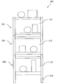
- a module structure is used in an oil refining processing plant, as shown in FIG. 15, it is possible to construct a plant structure 102 by laminating the module structure 106.
- the conditions for transporting the module structure 106 are also different.
- the module structure 106 is loaded on a container ship and transported on a river, then transshipped by a transportation means such as a truck and transported on an expressway to the site. Will be transported to.
- a transportation means such as a truck and transported on an expressway to the site. Will be transported to.
- the modular structure 106 transshipped from a container ship to a means of transportation such as a truck at a port is transported by land to the yard of the construction site of an oil refining plant.
- a means of transportation such as a truck at a port
- each module structure 106 adopts a box type having one hierarchical space 112
- a large number of steel frames is required and the manufacturing cost increases. There was a problem of doing.
- An object of the present invention is to provide an inexpensive split transport module that can be easily transported anywhere, a plant structure using the split transport module, and a method for constructing the plant structure.
- the split transport module of the present invention A module for split transport that is split and transported and stacked at a construction site. Pillars erected in the vertical direction and Equipped with a horizontal section that is erected in the horizontal direction The horizontal portion is characterized in that it directly divides vertically adjacent hierarchical spaces at the time of stacking. As a result, the overall height of the split transfer module can be reduced, and the overall weight can be reduced. Therefore, it is possible to provide an inexpensive divided transport module that can be easily transported anywhere.
- the module for split transfer of the present invention is At least one of the upper end or the lower end of the pillar portion is a free end that is not joined to the horizontal portion, and the height position of the free end is separated from the height position of the boundary of the hierarchical space. It is a feature. As a result, the structural members required for the conventional box-type module can be omitted, the number of steel frames can be reduced, and the manufacturing cost can be suppressed.
- the module for split transfer of the present invention is The split transport module, which is arranged in the lowermost layer when stacked, is characterized in that the column base does not project below the horizontal portion located at the lowermost side. As a result, the size of the divided transport module itself can be made compact, and the center of gravity during transport can be lowered.
- the module for split transfer of the present invention is At the time of transportation, the maximum height of the equipment installed is 3 m or more and 20 m or less. By suppressing the total height of the split transport module in this way, the weight of the split transport module can be reduced and the transport can be facilitated.
- the plant structure of the present invention is a structure for a plant constructed by laminating the above-mentioned divided transport modules.
- the maximum height when the device is installed is 5 m or more and 25 m or less. That is, by suppressing the total height of the split transfer module, such a compact plant structure can be realized.
- the structure for a plant of the present invention is A horizontal plate is formed at the end of the pillar.
- the upper and lower ends of the pillars are vertically joined by connecting the horizontal plates to each other with high-strength bolts.
- the structure for a plant of the present invention is The joint between the upper and lower end portions of the pillar portion is characterized in that a splice plate is arranged so as to straddle the upper and lower flange portions, and the flange portion and the splice plate are joined by connecting them with high-strength bolts. ..
- a splice plate is arranged so as to straddle the upper and lower flange portions, and the flange portion and the splice plate are joined by connecting them with high-strength bolts. ..
- the method for constructing a plant structure of the present invention is This is the method for constructing the above-mentioned plant structure.
- Mounting process of attaching the hanging bracket to the upper end of the pillar It is characterized by including an installation step of installing the divided transport module while simultaneously lifting all the pillars via the hanging metal fittings.
- By adopting the method of attaching the hanging metal fittings and lifting them in this way it is possible to improve the work speed of the work of lifting the divided transport module. Further, by lifting all the pillars at the same time, it is possible to prevent the balance from being lost, such as the shape of the divided transport module being lost.
- the construction method of the structure for a plant of this invention Column base erection process, in which the column base is erected vertically on the foundation, It is characterized by including a brace attachment step of crossing and bridging column base braces between the column bases.
- the lowermost layer of the split transport module can be prevented from having a column base, and the total height of the lowermost layer of the split transport module can be suppressed.
- the proof stress against a horizontal load can be improved by bridging the column base brace.
- the present invention it is possible to provide an inexpensive divided transport module that can be easily transported anywhere, a plant structure using the split transport module, and a method for constructing the plant structure.
- FIG. 1 is a diagram showing an outline of a plant structure according to an embodiment.
- the plant structure 2 is configured by stacking a plurality of divided transport modules 6 on a column base 4.
- FIG. 1 shows only one frame constituting one surface of the plant structure 2 in the beam-to-beam direction, in reality, a plurality of frames shown in FIG. 1 are continuous in the depth direction of FIG. It is provided.
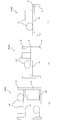
- FIG. 2 is a diagram showing a state in which each of the divided transport modules 6 constituting the plant structure 2 is disassembled.
- each of the divided transport modules 6 is divided and transported, and is laminated at the construction site.
- the pillar portion 8 is erected in the vertical direction and the horizontal is erected in the horizontal direction. It is composed of a frame 10.
- a device 14 is installed on each pillar portion 8.
- the maximum height of each of the divided transport modules 6 in the state where the device 14 is installed is 3 m or more and 20 m or less.
- a hierarchical space 12 is formed as a space surrounded by the pillar portion 8 and the horizontal portion 10 in the plant structure 2 in which the divided transport modules 6 are laminated, and the hierarchical space 12 is formed. Each layer is defined by 12.
- the height of the plant structure 2 in the state where the equipment 14 is installed is 5 m or more and 25 m or less.
- each of the divided transport modules 6 does not adopt the box type in which each of the divided transport modules 6 constitutes one hierarchical space 112 as in the module structure 106 shown in FIG. 15, and as shown in FIG.
- Each of the horizontal portions 10 directly divides the hierarchical spaces 12 adjacent to each other at the time of stacking. In the direct division by the horizontal portion 10, the space formed in the first divided transport module 6a by the column base portion 4 and the space on the third divided transport module 6c are also considered as the hierarchical space 12.
- the upper end or the lower end of the pillar portion 8 constitutes a free end 9 which is not joined to the horizontal portion 10.
- the lower end of the pillar portion 8 is rigidly joined to the horizontal portion 10, but the upper end of the pillar portion 8 protrudes above the horizontal portion 10 and is free. It constitutes the end 9.
- the horizontal portion 10 is located near the center of the second split transport module 6b in the vertical direction, and both the upper end and the lower end of the pillar portion 8 form the free end 9. ing.
- the upper end of the pillar portion 8 is rigidly joined to the horizontal portion 10, but the lower end of the pillar portion 8 protrudes below the horizontal portion 10 and is a free end. 9 is configured.
- the height position of the free end 9 is the boundary of the hierarchical space 12 in the laminated state. It is separated from the height position.
- the joint portion between the pillar portion 8 of the first split transport module 6a and the pillar portion 8 of the second split transport module 6b is located near the center of the hierarchical space 12 on the second floor, and the second split transport module 6b.
- the joint portion between the pillar portion 8 and the pillar portion 8 of the third divided transport module 6c is located near the center of the hierarchical space 12 on the third floor.
- the column base of the first divided transport module 6a arranged in the lowermost layer when laminated does not project below the lower horizontal portion 10. .. That is, the column base portion 4 is not included in the split transport module 6. This is in contrast to the plant structure 102 shown in FIG. 15, in which the column base 114 of the lowermost module structure 106 protrudes. Therefore, in the plant structure 2 according to the embodiment, the column base portion 4 is assembled on-site as described later. Since the column base of the first split transport module 6a does not protrude below the lower horizontal portion 10, the size of the first split transport module 6a itself is made compact and the center of gravity during transport is lowered. be able to.
- each of the divided transport modules 6 is assembled in advance at a steel frame processing factory, and is carried into a container ship with the equipment 14 installed. Then, after being unloaded at the port, it is loaded onto a transportation means such as a truck (not shown).
- the first split transport module 6a, the second split transport module 6b, and the third split transport module 6c loaded on the transportation means such as a truck are used to construct the plant structure 2 in the oil refining plant. It will be transported by land to the site. In this land transportation route, the split transport module 6 loaded on the transportation means such as a truck needs to dive under many cables laid between the towers, and each split transport module 6 is a device 14. Since the height is limited so that the height in the installed state is 3 m or more and 20 m or less, the split transfer module 6 does not get caught in the cable.
- the split transport module 6 transported by land by a transportation means such as a truck is loaded and unloaded in a yard 19 (see FIG. 4) provided near the construction site of the plant structure 2.
- a transportation means such as a truck
- the foundation 20 is arranged in advance, and the column base 4a is erected on the foundation 20 (column base erection step).
- the hanging metal fitting 24 is attached to the upper end of the pillar portion 8 of the first split transport module 6a to be lifted first (attachment step).
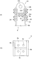
- the pillar portion 8 is formed of H-shaped steel, and a horizontal plate 8a is fixed to the upper end of the pillar portion 8.
- FIG. 3B is a cross-sectional view of the pillar portion 8 as viewed from below.
- bolt holes 8d are formed between the flanges 8b of the horizontal plate 8a with the web 8c interposed therebetween.
- a horizontal plate 24a having a bolt hole 24d formed is fixed below the hanging metal fitting 24.
- the horizontal plate 24a of the hanging bracket 24 is placed on the horizontal plate 8a of the pillar portion 8 by aligning the positions of the bolt holes 24d and 8d.
- the horizontal plates 24a and 8a are connected to each other by high-strength bolts 28.
- the splice plate 30 is arranged so as to straddle the flange 24b of the hanging metal fitting 24 and the flange 8b of the pillar portion 8.
- bolt holes are formed in the flange 24b of the hanging metal fitting 24, the flange 8b of the pillar portion 8, and the splice plate 30, respectively, and the splice plate 30 positions the flanges 24b, 8b and the bolt holes, respectively. It is arranged together.
- the flanges 24b and 8b and the splice plate 30 are joined by high-strength bolts 28. Such work is repeated at the upper ends of all the pillars 8 of the first split transport module 6a.
- heavy machinery 32 is arranged at the construction site of the plant structure 2.
- a wire 32b is hung on the tip of the arm 32a of the heavy machine 32, and a spreader beam 34 is hung below the wire 32b.
- a suspension wire 34b for suspending the beam main body 34a and a holder wire 34c suspended at both ends of the beam main body 34a are attached to the spreader beam 34.
- the first division transport module 6a has an unstable structure in which a free end 9 is configured at the upper end of the pillar portion 8. In this way, by lifting all the hanging metal fittings 24 at the same time, the first division is performed. It is possible to prevent the balance from being lost, such as the shape of the transport module 6a being lost.
- the hanging metal fittings 24 can be lifted in the vertical direction by the respective hanging wires 34b, and the central direction of the first split transport module 6a.
- the force of the force acts on the pillar portion 8 to prevent the pillar portion 8 from tilting.
- the first split transport module 6a is installed on the column base 4a with all the hanging metal fittings 24 being lifted at the same time (installation process).
- the arm 32a is moved onto the column base 4a with the first divided transfer module 6a suspended, and as shown in FIG. 5, all the column portions included in the first divided transfer module 6a. Align the lower end of 8 with the position of the column base 4a.
- the horizontal plate 4f having the bolt holes 4e formed at the upper ends of the column bases 4a was fixed (see FIG. 6), and the bolt holes 8e were also formed at the upper ends of the column portions 8.
- the horizontal plate 8a is fixed. Therefore, when attaching the first divided transport module 6a to the column base 4a, first, as shown in FIG.
- the bolt holes 4e and 8e are aligned and the horizontal plate 8a of the column portion 8 is attached to the column base 4a.
- the horizontal plates 4f and 8f are connected to each other with a high-strength bolt 28.
- the splice plate 30 is placed across the joint between the column base 4a and the column portion 8 and fastened with a high-strength bolt 28. To form a rigid joint (see FIG. 11).
- the brace 36 is crossed between the column bases 4a in an X shape (brace attachment step) to form the column base portion 4.
- the upper end of the brace 36 is connected to the flange 10b of the horizontal portion 10 via the splice plate 30 with a high-strength bolt 28.
- the brace 36 is not necessarily X-shaped, and as shown in FIG. 8B, a compression brace 36'may be used.
- a filler plate 38 is further arranged between the flange of the column base 4a and the splice plate 30.
- the high-strength bolt 28 is removed from the hanging bracket 24 attached to the pillar 8 of the first split transport module 6a, and the hanging bracket 24 is pulled away from the pillar 8 as shown in FIG.
- the hanging metal fitting 24 moves together with the spreader beam 34 while being suspended from the holder wire 34c.
- the heavy machine 32 is operated to move the spreader beam 34 to the yard 19 again, and the hanging metal fitting 24 suspended from the holder wire 34c is attached to the second split transport module 6b integrated in the yard 19.
- the hanging metal fitting 24 is attached in the same manner as in the case of the first divided transfer module 6a described with reference to FIG.
- the arm 32a is moved onto the first divided transport module 6a in a state where the second split transport module 6b is suspended, and as shown in FIG. 11, for the second split transport.
- the lower ends of all the pillars 8 included in the module 6b are aligned with the upper ends of the pillars 8 of the first split transport module 6a.
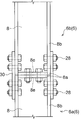
- the bolt holes 8e are aligned with each other and stacked on the horizontal plates 8a of the upper and lower pillar portions 8, and then the horizontal plate 8a Connect each other with high-strength bolts 28.
- the splice plate 30 is arranged so as to straddle the flanges 8b of the upper and lower pillar portions 8, and the upper and lower flanges 8b and the splice plate 30 are connected by high-strength bolts 28.
- Bolt holes are formed in the flanges 8b and the splice plate 30 of the upper and lower pillar portions 8, and the splice plates 30 are brought into contact with the respective flanges 8b by aligning the positions of the bolt holes.
- the splice plate 30 By connecting the horizontal plates 8a to each other with high-strength bolts 28 and further arranging the splice plates 30 so as to straddle the flanges 8b of the upper and lower pillars 8, the pillars 8 of the first split transport module 6a are arranged.
- the pillar portion 8 of the second split transport module 6b is rigidly joined to the top.
- the third split transport module 6c is further laminated on the second split transport module 6b.
- the hanging metal fitting 24 is attached and the upper and lower pillars 8 are joined in the same manner as when the second divided transfer module 6b is attached to the first divided transfer module 6a.
- the third division transfer module 6c is laminated on all the frames existing in the depth direction, the plant structure 2 is completed. After the work, the hanging metal fitting 24 is collected for reuse.
- the total height of the split transport module 6 is low because each of the horizontal portions 10 has a configuration that directly divides the vertically adjacent hierarchical spaces 12 at the time of stacking. Therefore, the total weight can be reduced. Therefore, it is possible to provide an inexpensive divided transport module that can be easily transported anywhere.
- At least one of the upper end or the lower end of the pillar portion 8 constitutes a free end 9 which is not joined to the horizontal portion 10, and the height position of the free end 9 is the height of the boundary of the hierarchical space 12 in a laminated state. It is separated from the position, and a part of the horizontal portion required for the conventional box-type module structure 106 can be omitted. Therefore, the number of steel frames can be reduced and the manufacturing cost can be suppressed.
- the assembly work of the split transport module at the site is minimized and safety is achieved as compared with the case of connecting by welding. It is possible to improve the sex and work speed.
- the first split transport module 6a when the first split transport module 6a is installed on the column base 4a, it is not always necessary to rely on the spreader beam 34.
- a self-propelled trolley such as SPMT (Self-Propelled Modular Transport) having a lift function capable of raising and lowering may be used.
- SPMT Self-Propelled Modular Transport
- the split transport module 6 unloaded from the container ship is loaded onto the SPMT 42.
- the split transport module 6 loaded on the SPMT 42 is transported by land to the construction site of the plant structure 2 in the oil refining processing plant.
- the SPMT 42 loaded with the second split transport module 6b and the SPMT 42 loaded with the third split transport module 6c are on standby in the vicinity of the construction site.
- the installation work of the first split transport module 6a is performed as it is. That is, as shown in FIG. 13 (a), the SPMT 42 loaded with the first divided transport module 6a approaches the plant structure 2'under construction, and as shown in FIG. 13 (b), as it is. Enter the plant structure 2'under construction.
- the first split transport module 6a is lowered by the lift function of the SPMT 42, and the column base is lowered. Install on 4a.
- the column portion 8 is connected to the column base 4a by using the high-strength bolt 28 in the same manner as described with reference to FIG.
- the horizontal plate 8a is used in consideration of stability when connecting the column portion 8 to the column base 4a. It is preferable to use and rigidly join (see FIG. 11).
- the SPMT 42 is removed from the plant structure 2'under construction, and then as shown in FIG. 14 (b).
- the brace 36 is attached to the column base 4a in an X shape.
- the compression brace 36' may be used instead of the brace 36. (See FIG. 8 (b)).
- the second divided transfer module 6b and the third divided transfer module 6c are installed by suspending them using the heavy machine 32 in the same manner as described with reference to FIGS. 10 to 12.
- the split transport module 6 unloaded at the port may be once transported to the construction site by a transport means such as a truck, and then transshipped to the SPMT 42. At this time, the transshipment may be performed by the heavy machine 32.
- the divided transfer module 6 includes three types of the first divided transfer module 6a, the second divided transfer module 6b, and the third divided transfer module 6c is taken as an example.
- the number and types of divided transport modules 6 included in one plant structure 2 are not limited to those described above.
- the column base may protrude below the horizontal portion 10 on the lower side of the first split transport module 6a.
- the maximum height of the first split transport module 6a is suppressed to 3 m or more and 20 m or less, and the protrusion of the column base is suppressed to the minimum.
- the high-strength bolt 28 is used as a member for joining the plates and the like, but for example, a friction joint joint other than the high-strength bolt 28 such as a rivet may be used.
Landscapes
- Engineering & Computer Science (AREA)
- Architecture (AREA)
- Civil Engineering (AREA)
- Structural Engineering (AREA)
- Physics & Mathematics (AREA)
- Electromagnetism (AREA)
- Mechanical Engineering (AREA)
- Conveying And Assembling Of Building Elements In Situ (AREA)
- Packaging Of Annular Or Rod-Shaped Articles, Wearing Apparel, Cassettes, Or The Like (AREA)
Abstract
Description
分割して搬送され、建設現場で積層される分割搬送用モジュールであって、
鉛直方向に立設される柱部と、
水平方向に架設される横架部と
を備え、
前記横架部は、積層時に上下に隣接する階層空間を直接区分することを特徴とする。
これにより、分割搬送用モジュールの全高さが低くなり、全体重量を小さくすることができる。このため、何処においても容易に搬送できる安価な分割搬送用モジュールを提供することができる。
前記柱部の上端または下端の少なくとも一方は、前記横架部に接合されていない自由端であり、前記自由端の高さ位置が前記階層空間の境界の高さ位置と離間していることを特徴とする。
これにより、従来のボックス型モジュールで必要とされていた構造部材を省くことができ、鉄骨数量を削減することができるため、製造コストを抑制することができる。
積層された際に最下層に配置される該分割搬送用モジュールは、最も下側に位置する前記横架部の下方に柱脚が突出していないことを特徴とする。
これにより、分割搬送用モジュール自体のサイズをコンパクトにし、搬送時の重心を低くすることができる。
搬送時において、機器が据え付けられた状態の最高高さが3m以上20m以下であることを特徴とする。
このように、分割搬送用モジュールの全高を抑制することにより、分割搬送用モジュールの重量を軽量化することができ、搬送しやすくすることができる。
上述の分割搬送用モジュールを積層して建設されたプラント用構造物であって、
機器が据え付けられた状態の最高高さが5m以上25m以下であることを特徴とする。
すなわち、分割搬送用モジュールの全高を抑制することにより、このようにコンパクトなプラント用構造物を実現することができる。
前記柱部の端部には、水平プレートが形成され、
上下の前記柱部の端部は、前記水平プレート同士を高力ボルトで繋ぎ合わせることにより上下に接合されていることを特徴とする。
このように、高力ボルトを用いて接合することにより、現場における分割搬送用モジュールの組み立て作業を最小化し、安全性と作業速度を向上させることができる。
上下の前記柱部の端部の繋ぎ目は、上下のフランジ部分を跨いでスプライスプレートが配置され、前記フランジ部分とスプライスプレートを高力ボルトで繋ぎ合わせることにより接合されていることを特徴とする。
これにより、分割搬送用モジュールの繋ぎ目において、的確にモーメントを伝達させるように接合することができる。
上述のプラント用構造物の建設方法であって、
前記柱部の上端に吊金具を取り付ける取付工程、
前記吊金具を介してすべての前記柱部を同時に吊り上げながら前記分割搬送用モジュールを据え付ける据付工程
を含むことを特徴とする。
このように、吊金具を取り付けて吊り上げる方法を採用することにより、分割搬送用モジュールを吊り上げる作業の作業速度を向上させることができる。また、すべての柱部を同時に吊り上げることにより、分割搬送用モジュールの形状が崩れるなど、バランスを崩さないようにすることができる。
基礎上に柱脚を鉛直方向に立設する柱脚立設工程、
前記柱脚間に柱脚ブレースを交差して架け渡すブレース取付工程
を含むことを特徴とする。
これにより、最下層の分割搬送用モジュールが柱脚を備えないようにし、最下層の分割搬送用モジュールの全高を抑制することができる。また、柱脚ブレースを架け渡すことにより、水平荷重に対する耐力を向上させることができる。
2´ 建設中のプラント用構造物
4 柱脚部
4a 柱脚
4e ボルト孔
4f 水平プレート
6 分割搬送用モジュール
6a 第1分割搬送用モジュール
6b 第2分割搬送用モジュール
6c 第3分割搬送用モジュール
8 柱部
8a 水平プレート
8b フランジ
8c ウェブ
8d ボルト孔
8e ボルト孔
9 自由端
10 横架部
10b フランジ
12 階層空間
14 機器
19 ヤード
20 基礎
24 吊金具
24a 水平プレート
24b フランジ
24d ボルト孔
24k 穴部
28 高力ボルト
30 スプライスプレート
32 重機
32a アーム
32b ワイヤ
34 スプレッダビーム
34a ビーム本体
34b 吊ワイヤ
34c ホルダワイヤ
36 ブレース
36´ 圧縮ブレース
38 フィラープレート
42 SPMT
102 プラント用構造物
106 モジュール構造物
112 階層空間
114 柱脚
Claims (9)
- 分割して搬送され、建設現場で積層される分割搬送用モジュールであって、
鉛直方向に立設される柱部と、
水平方向に架設される横架部と
を備え、
前記横架部は、積層時に上下に隣接する階層空間を直接区分することを特徴とする分割搬送用モジュール。 - 前記柱部の上端または下端の少なくとも一方は、前記横架部に接合されていない自由端であり、前記自由端の高さ位置が前記階層空間の境界の高さ位置と離間していることを特徴とする請求項1記載の分割搬送用モジュール。
- 積層された際に最下層に配置される該分割搬送用モジュールは、最も下側に位置する前記横架部の下方に柱脚が突出していないことを特徴とする請求項1または2記載の分割搬送用モジュール。
- 搬送時において、機器が据え付けられた状態の高さが3m以上20m以下であることを特徴とする請求項1~3の何れか一項に記載の分割搬送用モジュール。
- 請求項1~4の何れか一項に記載の分割搬送用モジュールを積層して建設されたプラント用構造物であって、
機器が据え付けられた状態の高さが5m以上25m以下であることを特徴とするプラント用構造物。 - 前記柱部の端部には、水平プレートが形成され、
上下の前記柱部の端部は、前記水平プレート同士を高力ボルトで繋ぎ合わせることにより上下に接合されていることを特徴とする請求項5記載のプラント用構造物。 - 上下の前記柱部の端部の繋ぎ目は、上下のフランジ部分を跨いでスプライスプレートが配置され、前記フランジ部分とスプライスプレートを高力ボルトで繋ぎ合わせることにより接合されていることを特徴とする請求項6記載のプラント用構造物。
- 請求項6または7記載のプラント用構造物の建設方法であって、
前記柱部の上端に吊金具を取り付ける取付工程、
前記吊金具を介してすべての前記柱部を同時に吊り上げながら前記分割搬送用モジュールを据え付ける据付工程
を含むことを特徴とするプラント用構造物の建設方法。 - 基礎上に柱脚を鉛直方向に立設する柱脚立設工程、
前記柱脚間に柱脚ブレースを交差して架け渡すブレース取付工程
を含むことを特徴とする請求項8記載のプラント用構造物の建設方法。
Priority Applications (3)
| Application Number | Priority Date | Filing Date | Title |
|---|---|---|---|
| US17/630,165 US12312799B2 (en) | 2019-08-06 | 2019-08-06 | Module for separate conveyance, structure for plant, and method of constructing structure for plant |
| PCT/JP2019/030913 WO2021024382A1 (ja) | 2019-08-06 | 2019-08-06 | 分割搬送用モジュール、プラント用構造物、およびプラント用構造物の建設方法 |
| SA522431521A SA522431521B1 (ar) | 2019-08-06 | 2022-01-27 | وحدة للنقل المنفصل، هيكل لمصنع وطريقة لبناء هيكل لمصنع |
Applications Claiming Priority (1)
| Application Number | Priority Date | Filing Date | Title |
|---|---|---|---|
| PCT/JP2019/030913 WO2021024382A1 (ja) | 2019-08-06 | 2019-08-06 | 分割搬送用モジュール、プラント用構造物、およびプラント用構造物の建設方法 |
Publications (1)
| Publication Number | Publication Date |
|---|---|
| WO2021024382A1 true WO2021024382A1 (ja) | 2021-02-11 |
Family
ID=74502564
Family Applications (1)
| Application Number | Title | Priority Date | Filing Date |
|---|---|---|---|
| PCT/JP2019/030913 Ceased WO2021024382A1 (ja) | 2019-08-06 | 2019-08-06 | 分割搬送用モジュール、プラント用構造物、およびプラント用構造物の建設方法 |
Country Status (3)
| Country | Link |
|---|---|
| US (1) | US12312799B2 (ja) |
| SA (1) | SA522431521B1 (ja) |
| WO (1) | WO2021024382A1 (ja) |
Citations (4)
| Publication number | Priority date | Publication date | Assignee | Title |
|---|---|---|---|---|
| JPH07102637A (ja) * | 1993-10-08 | 1995-04-18 | Kajima Corp | 鋼管柱と鋼管柱の接合構造 |
| US20120279141A1 (en) * | 2011-05-06 | 2012-11-08 | Epsilon Industries Inc. | Modular building system and method |
| US20140137486A1 (en) * | 2011-06-28 | 2014-05-22 | Dsm Ip Assets B.V. | Modular multi-story production plant and methods for constructing same |
| US20180058060A1 (en) * | 2016-08-29 | 2018-03-01 | Solar Turbines Incorporated | Modular compression plant |
Family Cites Families (37)
| Publication number | Priority date | Publication date | Assignee | Title |
|---|---|---|---|---|
| US3881571A (en) * | 1973-10-19 | 1975-05-06 | Michael Maldwyn Moulton | Building unit for scaffolding or a trestle |
| US5412913A (en) * | 1993-05-28 | 1995-05-09 | Fluor Corporation | Self-aligning beam joint suited for use in modular construction |
| US20030167725A1 (en) * | 2002-03-07 | 2003-09-11 | Long Thomas L. | Method for constructing, transporting, and permanently installing modular building |
| US6829872B2 (en) * | 2002-03-19 | 2004-12-14 | William J. Wahlsteen | Process and device for connecting I-beams |
| US20070094946A1 (en) * | 2005-09-30 | 2007-05-03 | Ohio Transmission Corporation | Modular industrial equipment facility |
| US7607273B2 (en) * | 2006-09-08 | 2009-10-27 | Henderson Andrew G | Building member |
| CA2668216A1 (en) * | 2008-06-03 | 2009-12-03 | Atlantic Bioventure Centre | Modular portable micro-factory system |
| JP4282745B1 (ja) * | 2008-09-29 | 2009-06-24 | 積水化学工業株式会社 | 仮設補強部材付き建物ユニット及びユニット建物並びにユニット建物の構築工法 |
| JP5391836B2 (ja) | 2009-05-29 | 2014-01-15 | 株式会社日立製作所 | モジュール構造物及びプラントの建設工法 |
| US20110056147A1 (en) * | 2009-09-09 | 2011-03-10 | Patrice Beaudet | Load-bearing construction pod and hybrid method of construction using pods |
| AU2011223504B2 (en) * | 2010-03-03 | 2017-05-11 | Modconnect Group Pty Ltd | Improvements in prefabricated modular building units |
| SG11201402089UA (en) * | 2011-12-14 | 2014-06-27 | Marion Invest Ltd | Apparatus, systems and methods for modular construction |
| US10711476B2 (en) * | 2012-02-17 | 2020-07-14 | Future Proof, LLC | Modular utilities unit structure |
| EP2909387A4 (en) * | 2012-10-18 | 2016-11-23 | Merhis Pty Ltd | METHODS, SYSTEMS, AND COMPONENTS FOR MULTI-STAGE BUILDING CONSTRUCTION |
| US8875445B2 (en) * | 2012-10-29 | 2014-11-04 | Stephen Lee Lippert | Light weight modular units for staggered stacked building system |
| US9010037B1 (en) * | 2014-01-16 | 2015-04-21 | Alfredo I. Gonzalez | Intermodal concrete building unit |
| WO2015131334A1 (zh) * | 2014-03-04 | 2015-09-11 | 东莞市石西智能机器制造有限公司 | 一种建筑结构及其施工方法 |
| US9347222B2 (en) * | 2014-07-18 | 2016-05-24 | Herve Bottin | Welded roof for modular building units |
| IL239683B (en) * | 2015-06-29 | 2021-07-29 | Klein Amos | Multi-layer protective system |
| ITUB20169963A1 (it) * | 2016-01-13 | 2017-07-13 | Federico Lestini | Struttura di edificio modulare con relativi impianti integrati |
| US20170328055A1 (en) * | 2016-05-10 | 2017-11-16 | Martin Morales | Military Housing System |
| WO2018075718A1 (en) * | 2016-10-19 | 2018-04-26 | Powersecure, Inc. | Modular power generation facilities using shipping container-based modules |
| US10648169B2 (en) * | 2017-04-26 | 2020-05-12 | New House International Corp. | Packaged container housing structure and construction method |
| US12163328B2 (en) * | 2018-01-23 | 2024-12-10 | Qube Building Systems Inc. | Self-sealing building module with a self-aligning connector |
| US10640969B2 (en) * | 2018-02-17 | 2020-05-05 | BuildXGroup, Inc. | Cube coupling joint |
| EP3821087B1 (en) * | 2018-07-12 | 2025-03-19 | Z-Modular Holding, Inc | Locating pin assembly for a modular frame |
| US10920412B2 (en) * | 2018-12-29 | 2021-02-16 | Hall Labs Llc | Modular building unit and system |
| WO2020205951A1 (en) * | 2019-04-02 | 2020-10-08 | Bechtel Hydrocarbon Technology Solutions, Inc. | Construction system |
| GB2576964B (en) * | 2019-04-17 | 2020-09-09 | Peter Dann Ltd | Modular structure and connection method |
| EP3978711B1 (en) * | 2019-05-29 | 2025-09-03 | IMAC Engineering Co., Ltd. | Plant facility construction method and plant facility |
| US10907342B1 (en) * | 2020-02-07 | 2021-02-02 | Assembly OSM, Inc. | Connection node for modular building structures |
| EP4121609A1 (en) * | 2020-03-16 | 2023-01-25 | Cubit Building Company Ehf. | System for architectural modular building construction |
| KR102136077B1 (ko) * | 2020-03-19 | 2020-07-21 | 주식회사 엔알비 | 모듈을 이용한 이동가능 건축물의 시공방법 |
| US12077961B2 (en) * | 2021-02-11 | 2024-09-03 | United States Gypsum Company | Modular construction including fire-suppressing gasket |
| WO2022241263A2 (en) * | 2021-05-14 | 2022-11-17 | Mitek Holdings, Inc. | Connection of modular building units |
| US12247389B2 (en) * | 2021-09-21 | 2025-03-11 | Blokable, Llc | Hollow structural section connector and methods of use of same |
| US12352034B2 (en) * | 2022-02-25 | 2025-07-08 | United States Gypsum Company | Load bearing wall construction system using hollow structural sections |
-
2019
- 2019-08-06 US US17/630,165 patent/US12312799B2/en active Active
- 2019-08-06 WO PCT/JP2019/030913 patent/WO2021024382A1/ja not_active Ceased
-
2022
- 2022-01-27 SA SA522431521A patent/SA522431521B1/ar unknown
Patent Citations (4)
| Publication number | Priority date | Publication date | Assignee | Title |
|---|---|---|---|---|
| JPH07102637A (ja) * | 1993-10-08 | 1995-04-18 | Kajima Corp | 鋼管柱と鋼管柱の接合構造 |
| US20120279141A1 (en) * | 2011-05-06 | 2012-11-08 | Epsilon Industries Inc. | Modular building system and method |
| US20140137486A1 (en) * | 2011-06-28 | 2014-05-22 | Dsm Ip Assets B.V. | Modular multi-story production plant and methods for constructing same |
| US20180058060A1 (en) * | 2016-08-29 | 2018-03-01 | Solar Turbines Incorporated | Modular compression plant |
Also Published As
| Publication number | Publication date |
|---|---|
| SA522431521B1 (ar) | 2024-05-06 |
| US12312799B2 (en) | 2025-05-27 |
| US20220282474A1 (en) | 2022-09-08 |
Similar Documents
| Publication | Publication Date | Title |
|---|---|---|
| JP5169549B2 (ja) | 大梁ブロック吊上げ工法およびこれに利用されるジャッキアップステージ | |
| KR101194170B1 (ko) | 모듈러 건축물의 접합구조 및 그 시공방법 | |
| WO1994027003A1 (fr) | Procede d'assemblage de modules de zone d'une construction a structure en acier | |
| JP2018035556A (ja) | 屋根構造体の構築方法 | |
| CN106759909B (zh) | 一种下挂上承结构体系及其施工方法 | |
| CN109607399A (zh) | 一种安装屋顶网架的吊装工艺 | |
| CN103964300B (zh) | 顶升式加高设备 | |
| CN112796499A (zh) | 一种可移动可顶升的大承载施工平台及其使用方法 | |
| JP7548869B2 (ja) | 構造物の構築方法 | |
| JP2017031657A (ja) | 天井クレーン支持装置及び荷重受け部材 | |
| WO2021024382A1 (ja) | 分割搬送用モジュール、プラント用構造物、およびプラント用構造物の建設方法 | |
| CN210482352U (zh) | 一种高电压榫卯结构装配式主变基础 | |
| JP6814717B2 (ja) | 水平部材の取り付け方法および建物躯体の構築方法 | |
| JP6969646B2 (ja) | 上部工部材運搬設備および上部工部材運搬方法 | |
| JP2022009519A (ja) | 上部工部材運搬設備および上部工部材運搬方法 | |
| JP3826352B2 (ja) | デッキユニットの組付方法 | |
| JP4056137B2 (ja) | ユニット式建物 | |
| JPH08270081A (ja) | 架構構造物の施工方法 | |
| JP6411832B2 (ja) | 仮設梁接続部材及び構造物構築方法 | |
| CN224032210U (zh) | 逆作法施工空间下钢柱辅助安装装置 | |
| CN113979290B (zh) | 一种用于桥墩模块化施工的三维调节吊具 | |
| JPH0673783A (ja) | 鉄骨鉄筋コンクリート柱と鉄骨梁の施工工法 | |
| CN203922468U (zh) | 一种依附钢平台的单轨吊 | |
| JP2690822B2 (ja) | 低層建築物の鉄骨造建方工法 | |
| CN217129527U (zh) | 一种矿用的竖井结构 |
Legal Events
| Date | Code | Title | Description |
|---|---|---|---|
| 121 | Ep: the epo has been informed by wipo that ep was designated in this application |
Ref document number: 19940888 Country of ref document: EP Kind code of ref document: A1 |
|
| NENP | Non-entry into the national phase |
Ref country code: DE |
|
| 122 | Ep: pct application non-entry in european phase |
Ref document number: 19940888 Country of ref document: EP Kind code of ref document: A1 |
|
| NENP | Non-entry into the national phase |
Ref country code: JP |
|
| WWE | Wipo information: entry into national phase |
Ref document number: 522431521 Country of ref document: SA |
|
| WWG | Wipo information: grant in national office |
Ref document number: 522431521 Country of ref document: SA |
|
| WWG | Wipo information: grant in national office |
Ref document number: 17630165 Country of ref document: US |