WO2021020573A1 - ステープル取り外し装置 - Google Patents
ステープル取り外し装置 Download PDFInfo
- Publication number
- WO2021020573A1 WO2021020573A1 PCT/JP2020/029515 JP2020029515W WO2021020573A1 WO 2021020573 A1 WO2021020573 A1 WO 2021020573A1 JP 2020029515 W JP2020029515 W JP 2020029515W WO 2021020573 A1 WO2021020573 A1 WO 2021020573A1
- Authority
- WO
- WIPO (PCT)
- Prior art keywords
- staple
- removal
- wedge plate
- paper
- crown
- Prior art date
Links
Images


Classifications
-
- B—PERFORMING OPERATIONS; TRANSPORTING
- B25—HAND TOOLS; PORTABLE POWER-DRIVEN TOOLS; MANIPULATORS
- B25C—HAND-HELD NAILING OR STAPLING TOOLS; MANUALLY OPERATED PORTABLE STAPLING TOOLS
- B25C11/00—Nail, spike, and staple extractors
Definitions
- This disclosure relates to a staple removal device.
- Patent Documents 1 and 2 Conventionally, a technique relating to a staple removing device for removing staples from a bundle of paper has been disclosed (Patent Documents 1 and 2). This type of staple removing device removes staples from a bundle of paper by inserting a wedge-shaped plate between the bundle of paper and the crown portion of the staple.
- Patent Document 1 discloses a staple removing device in which a staple removing means is arranged at a position vertically lower than a sheet bundle and is driven by a driving means to remove staples from a vertically lower position. Further, in Patent Document 2, both legs of the staple needle are raised in a predetermined state in the step of raising the leg, and the central main body of the staple needle exposed on the binding paper is defined as the central main body of the staple needle and the surface of the binding paper. Disclosed is a staple removing device for staple needles, which comprises a needle pulling step of inserting a needle pulling standing piece that moves in parallel with an upright fork protruding piece that is inserted between the binding paper and the staple needle so as to be far apart from the staple paper. There is.
- the conventional staple removal device has the following problems. That is, in Patent Document 1, since the staple removing means rotates to remove the staple from the lower position, there is theoretically only one point where the height of the claw is maximum from the mounting table, and the staple to be removed is set as the above point. If it is not set correctly, there is a problem that the claws are not inserted between the crown portion of the staple and the paper surface, resulting in poor removal of the staple.
- Patent Document 2 since the needle pulling upright piece is translated, the removal point of the staple is not a point but a surface, but when the needle pulling upright piece moves in parallel with the mounting table, the tip portion thereof is the crown of the staple. There is a problem that the staple pulling stand cannot be smoothly inserted between the crown portion and the paper surface because it may be caught in the portion.
- the present invention makes it easy to insert the tip of the removing portion between the paper bundle and the crown portion of the staple when removing the staple from the paper bundle, and prevents the removal failure. It is an object of the present invention to provide a staple removal device.
- the first aspect of the present disclosure is a mounting table on which a stack of paper bound by staples is placed, a paper holding portion that holds the bundle of paper placed on the above-mentioned stand, and a position below the above-mentioned stand.
- a removing portion and a motor for moving the removing portion are provided, and the above-mentioned pedestal is provided with an opening from which the tip portion can protrude, and the tip portion is provided at least in front of the second position to the second position.
- the present invention relates to a staple removing device that moves while maintaining a state of protruding from the above-described stand through an opening until the staple is passed through.
- the tip of the removal portion is moved from the front of the second position until it passes through the second position in a state of protruding from the mounting table, the tip of the removal portion is moved between the paper bundle and the staple. It can be easily inserted, and it is possible to prevent the occurrence of removal defects during the removal operation.
- FIG. 5 is a plan view of the inside of the staple removing device when the removing portion according to the first embodiment is in the standby position. It is a top view of the drive part inside the staple removal device which concerns on 1st Embodiment.
- FIG. 11A It is a side view which shows the operation of the staple pulling mechanism which moves to the removal position which concerns on 1st Embodiment. It is a side view of the main part which shows the operation of the staple pulling mechanism shown in FIG. 12A. It is a perspective view which shows the operation of the paper holding mechanism in the standby position which concerns on 1st Embodiment. It is a perspective view which shows the operation of the paper holding mechanism which moves to a pressing position which concerns on 1st Embodiment.
- FIG. 19A is an enlarged view of a main part of the wedge plate and the mounting table shown in FIG. 19A. It is explanatory drawing of the operation of the wedge plate of the staple removal device which moves to the removal position which concerns on 2nd Embodiment. It is an enlarged view of the main part of the wedge plate and the mounting stand shown in FIG. 20A.
- FIG. 22A is an enlarged view of a main part of the wedge plate and the mounting table shown in FIG. 22A. It is explanatory drawing of the operation of the wedge plate of the staple removal device which moves to the removal position which concerns on 3rd Embodiment. It is an enlarged view of the main part of the wedge plate and the mounting stand shown in FIG. 23A. It is a side view of the staple removal device which concerns on 4th Embodiment.
- FIG. 26A is an enlarged view of a main part of the wedge plate and the mounting table shown in FIG. 26A. It is an exploded perspective view of the staple removal device which concerns on modification 1-1. It is a perspective view of the staple removal device which concerns on modification 1-1. It is a side view of the wedge plate which concerns on modification 1-1.
- FIG. 5 is a cross-sectional view taken along the line AA of the removal portion shown in FIG. 45A. It is a side view which shows the operation of the staple removal device. It is a side view which shows the operation of the staple removal device. It is a side view which shows the operation of the staple removal device. It is a side view which shows the operation of the staple removal device. It is a side view which shows the operation of the staple removal device. It is a side view which shows the operation of the staple removal device. It is a side view which shows the operation of the staple removal device. It is a side view which shows the operation of the staple removal device. It is a side view which shows the operation of the staple removal device.
- FIG. 4 is a cross-sectional view taken along the line BB of the wedge plate shown in FIG. 49A.
- FIG. 5 is a cross-sectional view taken along the line CC of the removal portion shown in FIG. 51A. It is a top view of the removal part which concerns on modification 3-4. It is a side view of the removal part which concerns on modification 3-4. It is a bottom view of the removal part which concerns on modification 3-4. It is a DD line sectional view of the removal part shown in FIG. 52A which concerns on modification 3-4. It is a top view of the removal part which concerns on modification 3-5. It is a side view of the removal part which concerns on modification 3-5. It is a bottom view of the removal part which concerns on modification 3-5.
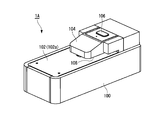
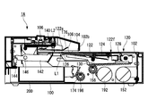
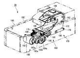
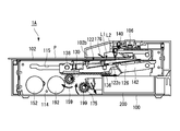
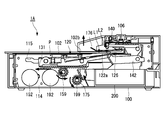
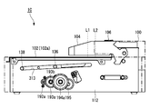
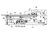
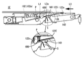
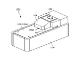
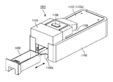
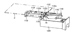
- FIG. 1A is a front perspective view of the staple removing device 1A
- FIG. 1B is a rear perspective view of the staple removing device 1A
- 2A is a right front left rear perspective view of the inside of the staple removing device 1A
- FIG. 2B is a left front right rear perspective view of the inside of the staple removing device 1A.
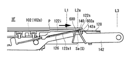
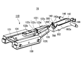
- the staple removing device 1A is a device for automatically removing (removing) staples from a bundle of paper bound by staples, and includes a housing 100 having a substantially rectangular parallelepiped shape and a mounting table 102 on which the bundle of paper is placed. , Located below the mounting table 102 (inside the housing 100 with respect to the mounting table 102), it drives the removing unit 120 and the removing unit 120 for removing staples from the paper bundle mounted on the mounting table 102.
- the first motor 152 and the accommodating portion 200 accommodating the staples removed by the removing unit 120 are provided.
- a cover portion 104 that covers a part of the mounting table 102 is provided above the mounting table 102 (the side on which the paper bundle is placed with respect to the mounting table 102).
- a predetermined gap is formed between the cover portion 104 and the mounting table 102, and a bundle of paper is inserted into this gap.
- An activation switch 106 for operating the staple removal device 1A is provided on the upper surface of the cover portion 104.
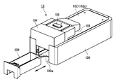
- the side where the accommodating portion 200 is provided is the rear side of the staple removal device 1A, and the opposite side is the front side of the staple removal device 1A.
- the housing 100 is a substantially rectangular parallelepiped box with an opening at the top, and a removing portion 120, a first motor 152, an accommodating portion 200, and the like are provided inside.
- the mounting table 102 is provided so as to cover the opening above the housing 100, and has a mounting surface 102a for mounting a bundle of paper.
- An opening 102b is formed on the mounting surface 102a so that a part of the removing portion 120 can be projected.
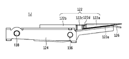
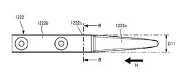
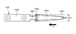
- the removing portion 120 has a predetermined length from the tip portion 122s to the base end portion 122k.
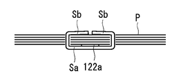
- the removing portion 120 includes a tip portion 122s that can be inserted between the paper bundle and the staple (crown portion Sa), and the wedge plate main body 122a, which is the first portion for removing the staple from the paper bundle, and racks 130 and 131. It has a wedge plate base portion 122f which is a second part driven by the driving force of the first motor 152 received in the above, and a constricted part 122c which is a third part located between the first part and the second part.
- the wedge plate body 122a is composed of an elongated plate-shaped member, and at least the tip portion 122s thereof is formed in a wedge shape so as to be easily inserted between the paper bundle and the staples and to easily pull out the staples from the paper bundle.
- the wedge plate main body 122a has a tapered shape from the base end portion 122k toward the tip end portion 122s. Specifically, in the side view, the plate thickness is gradually reduced from the base end portion 122k toward the tip end portion 122s, and in the top view, the plate width is gradually narrowed toward the tip end portion 122s. It is configured in.
- the wedge plate base 122f supports the wedge plate main body 122a via the constricted portion 122c, and also has a role of receiving the power from the first motor 152 by the racks 130 and 131 and transmitting it to the wedge plate main body 122a.
- the wedge plate base portion 122f includes a blade holder 124 formed of a flat plate having a substantially U-shaped cross section, and a pair of racks 130 and 131 attached to the side surfaces of the blade holder 124.
- a wedge plate main body 122a and an attachment portion 122b extending from the wedge plate base portion 122f are attached to the upper surface of the blade holder 124.
- the racks 130 and 131 are plate-shaped members having substantially the same length as the longitudinal direction of the blade holder 124, and a plurality of teeth (rack) that mesh with the pinion 158, which will be described later, are formed on the lower surface thereof, and the first motor 152. Receives the driving force of.
- a paper bundle insertion port 108 for setting a paper bundle in the cover portion 104 is provided between the mounting table 102 and the cover portion 104.
- the start switch 106 is provided on the upper surface of the cover portion 104 so that the user can easily operate it, and is composed of a button for operating the staple removing device 1A.
- the accommodating portion 200 is a box body having an opening at the upper side, and is configured to be removable with respect to the opening 100a formed on the rear end surface of the housing 100.
- the accommodating portion 200 is arranged in a space portion in the lower rear part of the housing 100 than the central portion.
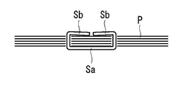
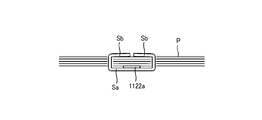
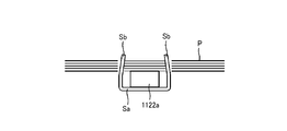
- the staple S in a state in which the paper bundle P is bound will be described with reference to FIG. 17A described later.
- the staple S has a crown portion Sa and a pair of leg portions Sb, Sb formed by bending both ends of the crown portion Sa in the longitudinal direction.
- the paper bundle P penetrates a pair of staples Sb, Sb from the bottom layer of a plurality of stacked sheets toward the top layer, and bends the penetrated legs Sb, Sb inward. It is bound by that.
- the binding position of the staple S is, for example, a corner or an edge of the paper. In the present embodiment, the staple S is removed from such a bundle of paper P.
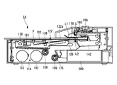
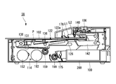
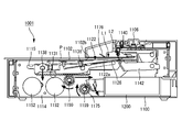
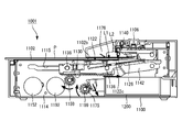
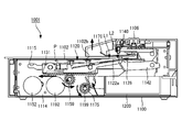
- FIG. 2A is a right front perspective view of the inside of the staple removing device 1A when the removing unit 120 is in the standby position
- FIG. 2B is a left front perspective view of the inside of the staple removing device 1A when the removing unit 120 is in the standby position
- FIG. 2C is a plan view of the inside of the staple removal device 1A when the removal unit 120 is in the standby position
- FIG. 2D is a plan view of the first drive unit 150 and the like inside the staple removal device 1A
- FIG. 2E shows the removal unit 120. It is a side view of the inside of the staple removal device 1A in the standby position.
- FIG. 3 is a side sectional view of the inside of the staple removing device 1A when the removing portion 120 is in the standby position.
- FIG. 4 is an exploded perspective view of the staple removing mechanism 110.
- 5A is a plan view of the removal unit 120
- FIG. 5B is a side view of the removal unit 120
- FIG. 5C is a cross-sectional view of the removal unit 120 along the line AA.
- FIG. 6 is an exploded perspective view of the paper holding mechanism 160.
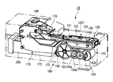
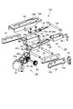
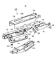
- the staple removing device 1A includes a staple removing mechanism 110 that removes the staple S from the paper bundle P, a paper holding mechanism 160 that presses the paper bundle P placed on the mounting table 102, and the above-mentioned accommodating portion 200. ing.
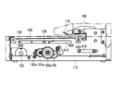
- the staple removing mechanism 110 is arranged inside the housing 100 below the mounting surface 102a of the mounting table 102, and is inserted between the paper bundle P and the staples to form a paper bundle. It has a removing unit 120 for removing staples S from P, a pressing unit 140 (regulating unit), and a first driving unit 150 for driving the removing unit 120.
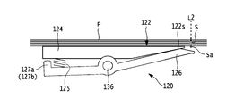
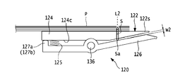
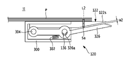
- the removing portion 120 has a wedge plate 122 inserted between the crown portion Sa of the staple S and the paper bundle P, and the wedge plate 122 of the crown portion Sa and the paper bundle P.
- the racks 130 and 131 to be moved between them are provided.
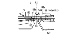
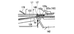
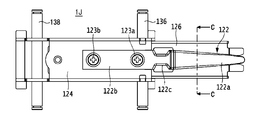
- a blade holder 124 to which the wedge plate 122 is attached a crown holder 126 that supports the crown portion Sa of the staple S, and a holder 128 that regulates the position of the wedge plate 122.
- a blade holder 124 to which the wedge plate 122 is attached a crown holder 126 that supports the crown portion Sa of the staple S
- a holder 128 that regulates the position of the wedge plate 122.
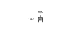
- the wedge plate 122 is composed of an elongated plate-shaped member, and includes a wedge plate main body 122a, a mounting portion 122b, and a constricted portion 122c.
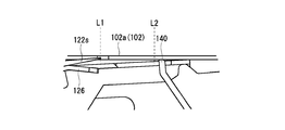
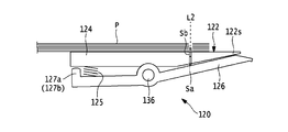
- the tip 122s is configured to be movable along the plane of the mounting table 102 between the standby position L1 and the removal position L2, and when the tip 122s moves to the removal position L2, the tip 122s is the paper bundle P and the staple. It is inserted between and.
- the standby position L1 of the removing unit 120 means a position where the tip portion 122s of the removing unit 120 is stopped before starting the removing operation.
- the removal position L2 of the removal unit 120 means that the removal unit 120 starts the removal operation, the removal unit 120 is inserted between the crown portion Sa of the staple S and the paper bundle P, and the staple S is removed from the paper bundle P. It means the position to start.
- the removal position L2 is a position at least horizontally separated from the standby position L1.
- the mounting portion 122b is integrally formed on the side of the base end portion 122k of the wedge plate main body 122a, and is mounted on the upper surface of the blade holder 124.
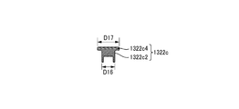
- the constricted portion 122c is a substantially central portion in the longitudinal direction of the wedge plate 122, and is formed between the wedge plate main body 122a and the mounting portion 122b. As shown in FIG. 5A, at least a part of the width dimension D1 of the constricted portion 122c is narrower than the width dimension D2 of the base end portion 122k of the wedge plate main body 122a, and when the staple S separates from the wedge plate 122, The width dimension D3 (see FIG.
- the "width dimension” means the dimension in the width direction of the wedge plate.
- the "width direction” is the left-right direction in this embodiment, and may be a direction perpendicular to the thickness direction (height direction) and the longitudinal direction (movement direction of the wedge plate) of the wedge plate.
- the blade holder 124 is composed of a flat plate having a substantially U-shaped cross section, a mounting portion 122b is mounted on the upper surface, and the blade holder 124 is arranged so as to be overlapped above the crown holder 126.
- the crown holder 126 is arranged below the wedge plate 122 with the blade holder 124 in between, and supports the crown portion Sa of the staple S removed from the paper bundle P.
- the crown holder 126 has a groove portion 126a for preventing contact with the pressing portion 140 when the wedge plate 122 moves from the front to the rear, and a staple S removed from the paper bundle P for dropping the staple S into the accommodating portion 200.
- the opening 126b of the crown holder 126 and the constricted portion 122c of the wedge plate 122 attached to the blade holder 124 are arranged so as to be in the same position in a plan view.
- the groove portion 126a is cut out from the tip end portion of the crown holder 126 to substantially the center portion, and has a width slightly wider than the width of the pressing portion 140.
- the opening 126b is formed at a substantially central portion in the longitudinal direction of the crown holder 126 and continuously on the proximal end side of the groove portion 126a, and has a width at least wider than the length of the crown portion Sa of the staple S.
- a spring 125 is arranged between the lower surface on the other end side of the blade holder 124 and the upper surface on the other end side of the crown holder 126, and the elastic force of the spring 125 causes one end side of the wedge plate 122 and one end side of the crown holder 126. Is urged in the direction of approaching.
- one end side indicates the rear side of the staple removal device 1A
- the other end side indicates the front side of the staple removal device 1A.
- the restricting portions 127a and 127b are integrally formed on the upper surface of the crown holder 126 on the base end side and at both ends in the width direction, and face the blade holder 124 side from the upper surface thereof. Is protruding.
- the regulating portions 127a and 127b come into contact with the lower surface 124c of the blade holder 124 when the tip end side of the crown holder 126 is opened to a preset opening amount (hereinafter referred to as a set value) with respect to the wedge plate 122, and the crown holder 126 It is regulated so that the tip side of is not opened more than the set value.
- the regulating portions 127a and 127b may be formed of a member different from the crown holder 126. Further, the shape of the regulating portions 127a and 127b is, for example, a rectangular shape having a curved upper end, but the shape is not limited to this shape as long as it can abut on the crown holder 126.
- a spring 125 is arranged.
- the load of the spring 125 is set according to the staple S having a smaller wire diameter among the staples S to be used.
- the holder 128 is composed of a flat plate having a substantially U-shaped cross section, and is arranged so as to be overlapped on the upper surface of the blade holder 124.
- the holder 128 has an opening 128a that exposes the wedge plate 122, and a support 128b that regulates the holding portion 140 to be located below the mounting table 102 when at least the removing portion 120 is stopped at the standby position L1. And include.
- a plate-shaped rack 130 having substantially the same length as the longitudinal direction of the blade holder 124 is arranged on the left side of the blade holder 124.
- the rack 130 receives the driving force of the first motor 152.
- a plurality of teeth that mesh with the pinion 158, which will be described later, are formed on the lower surface of the rack 130.
- a plate-shaped rack 131 having substantially the same length as the longitudinal direction of the blade holder 124 is arranged on the right side of the blade holder 124.
- the rack 131 receives the driving force of the first motor 152.
- a plurality of teeth that mesh with the pinion 159, which will be described later, are formed on the lower surface of the rack 131.
- a sensor 134 for detecting the position of the removal unit 120 is provided on the left side of the rack 130, and a flag mounting plate 132 for detecting the position of the removal unit 120 in the front-rear direction is provided. ..
- a first flag 132a for detecting the movement of the wedge plate 122 from the standby position L1 to the removal position L2 is provided at the rear end of the flag mounting plate 132.
- a second flag 132b for detecting the arrival of the wedge plate 122 at the removal position L2 is provided at the front end portion of the flag mounting plate 132.
- the sensor 134 is composed of a transmissive sensor and detects the first flag 132a and the second flag 132b of the rack 130 moving in the front-rear direction.
- the detection signal detected by the sensor 134 is supplied to a control unit (not shown), and the control unit controls the operations of the first motor 152 and the second motor 192 based on the detection signal supplied from the sensor 134.
- the first drive shaft 136 is located substantially in the middle between the tip end side and the base end side of the removal portion 120, and is engaged with the guide groove 113 of the left frame 112 and the guide groove 115 of the right frame 114, respectively.
- the first drive shaft 136 is inserted into the openings formed in each of the flag mounting plate 132, the rack 130, the blade holder 124, the crown holder 126, and the rack 131 from the left side to the right side of the housing 100.
- the spring 125 and the regulating portions 127a and 127b are arranged on the proximal end side of the crown holder 126 with respect to the first drive shaft 136.
- the second drive shaft 138 is located at the base end of the removing portion 120 and is engaged with the guide groove 113 of the left frame 112 and the guide groove 115 of the right frame 114, respectively.
- the second drive shaft 138 is inserted into the openings formed in the flag mounting plate 132, the rack 130, the blade holder 124, and the rack 131 from the left side to the right side of the housing 100.
- the wedge plate 122, the blade holder 124, the crown holder 126, the holder 128, the racks 130, 131, and the flag mounting plate 132 are assembled by the first drive shaft 136 and the second drive shaft 138 to remove the removal unit 120. It is configured so that it can be integrally moved forward and backward as a removing portion 120.
- the holding portion 140 that regulates the movement of the paper bundle P and the staple S in the insertion direction is arranged on the rear side of the crown portion Sa at the removal position L2 and pushed by the wedge plate 122. It is configured so that it can come into contact with the crown portion Sa.
- the width of the pressing portion 140 is selected, for example, to a length that can support the crown portion Sa that moves from the front to the rear by the pushing force of the wedge plate 122 and that can be inserted into the groove portion 126a of the crown holder 126.
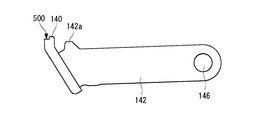
- the presser holder 142 that supports the presser portion 140 is formed of a flat plate processed into a substantially U shape in a top view, and the rear end side of the presser holder 142 is rotatably supported by a shaft 146.
- One end of the tension spring 144 is attached further behind the shaft 146 of the holding holder 142.
- the other end of the tension spring 144 is attached to the left frame 112.
- a convex portion 142a that can come into contact with the support portion 128b of the holder 128 is provided at the upper end portion on the front side of the holding holder 142.
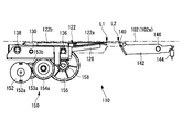
- the first drive unit 150 includes the first motor 152, the gear 153a connected to the output shaft 152a of the first motor 152, and the like in the width direction of the housing 100.
- a pair of pinions 158, 159 provided at both ends of a shaft 156, which are first pinion portions arranged at predetermined intervals to mesh with racks 130 and 131.
- the plurality of gears 153a, 153b, 154a, 154b, and 155 form a reduction mechanism.
- the first motor 152 has an output shaft 152a and a motor body 152b, and is composed of, for example, a DC motor, a DC brushless motor, or the like.
- the driving force of the first motor 152 is transmitted to the removal unit 120 via the reduction mechanism, and the removal unit 120 is moved forward or backward.
- the first motor 152 includes a removing portion 120 when the tip portion 122s of the wedge plate main body 122a (first portion) of the removing portion 120 is in the standby position L1. In the embodiment, it is arranged below the second part.
- the lower part of the removal unit 120 means that at least a part of the first motor 152 including the output shaft 152a is located directly below the removal unit 120.
- the first motor 152 is arranged so that the output shaft 152a is parallel to or substantially parallel to the mounting surface 102a of the mounting table 102, as shown in FIGS. 2D and 3 and the like.
- the output shaft 152a of the first motor 152 is arranged so as to be orthogonal to the moving direction of the wedge plate 122 from the front to the rear (longitudinal direction of the housing 100).
- substantially parallel means to include a range slightly deviated from perfect parallelism. This range may be, for example, within ⁇ 5 °, but may be within ⁇ 10 ° depending on the required accuracy.
- the gears 153a and 153b are two-stage drive gears, and the diameter of the gear 153a is larger than the diameter of the gear 153b.
- the gear 153a is connected to the output shaft 152a of the first motor 152.
- the gear 153b meshes with the gear 154a.
- the gears 154a and 154b are two-stage drive gears, and the diameter of the gear 154a is larger than the diameter of the gear 154b.
- the gear 154a meshes with the gear 153b, and the gear 154b meshes with the gear 155.
- the right end portion of the shaft 156 extending in the width direction of the housing 100 is attached.
- a pinion 159 that meshes with the rack 131 is attached to the right end side of the shaft 156 on the gear 155 side, and a pinion 158 that meshes with the rack 130 is attached to the left end side on the opposite side.
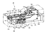
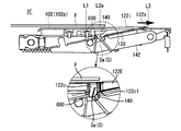
- FIGS. 2A and 6 and the like At least a part of the paper holding mechanism 160 for holding the paper bundle P mounted on the mounting table 102 is located above the mounting table 102 and is configured to be movable. It includes a paper holding portion 170 and a second motor 192 that drives the paper holding portion 170.
- the paper holding portion 170 includes a hold lever 172 to which the parts constituting the paper holding portion are attached, a pair of paper holding racks 174 and 175 extending in the traveling direction at predetermined intervals in the width direction of the housing 100, and a mounting table. It has a paper holding plate 176 which is a holding portion for holding the paper bundle P placed on the 102.
- the hold lever 172 has a pair of flat plates 172a and 172b arranged on the rear side of the housing 100 and arranged at predetermined intervals in the width direction.
- the lower side of the flat plates 172a and 172b is arranged inside the housing 100, and the upper side thereof is arranged so as to be exposed from the mounting table 102 and is covered with the cover portion 104.
- a boss 178 projecting outward is attached to the outer surface of the flat plate 172a.
- One end of the return spring 180 composed of a tension spring is attached to the boss 178, and the other end of the return spring 180 is attached to the left frame 112.
- a boss (not shown) is attached to the outer surface of the flat plate 172b, one end of the return spring 181 is attached to this boss, and the other end of the return spring 181 is attached to the right frame 114.
- the paper holding rack 174 is provided at the lower front end of the flat plate 172a of the hold lever 172.
- the paper retainer rack 174 is substantially fan-shaped and meshes with the paper retainer pinion 198.
- the paper holding rack 175 is provided at the lower front end of the flat plate 172b of the hold lever 172.
- the paper retainer rack 175 has a substantially fan shape and meshes with the paper retainer pinion 199 of the second drive unit 190.
- the paper retainer racks 174 and 175 convert the rotational motion of the paper retainer pinions 198 and 199 into a substantially linear motion.
- the paper holding plate 176 moves toward the mounting surface 102a so that the paper bundle P does not deviate from the removal position L2 of the mounting table 102 during the removal operation of the staple S, so that the mounting table 102 It is configured so that the paper bundle P placed on the paper can be pressed.
- the paper holding plate 176 is attached to the flat plates 172a and 172b so as to be parallel to or substantially parallel to the mounting table 102. Specifically, the left side surface of the paper holding plate 176 is supported by the shaft 186, and the right side surface of the paper holding plate 176 is supported by the shaft 187.
- the second drive unit 190 includes the second motor 192, the gear 193a connected to the output shaft 192a of the second motor 192, and the housing 100.
- the plurality of gears 193a, 193b, 194a, 194b, 195 constitute a reduction mechanism.
- the second motor 192 is arranged below the removal unit 120 when it is located at the standby position L1.
- the second motor 192 has an output shaft 192a and a motor body 192b, and is composed of, for example, a DC motor, a DC brushless motor, or the like.
- the second motor 192 is driven based on an instruction from a control unit (not shown) to transmit the driving force of the second motor 192 to the paper holding unit 170 via the reduction mechanism to operate the paper holding unit 170.
- the second motor 192 is behind the first motor 152, and the tip portion 122s of the wedge plate 122 of the removing portion 120 is in the standby position L1.
- the removal unit 120 in the case is arranged below the second unit in the present embodiment.
- the lower part of the removal unit 120 means that at least a part of the second motor 192 including the output shaft 192a is located directly below the removal unit 120.
- the output shaft 192a of the second motor 192 is arranged so as to be parallel to or substantially parallel to the mounting surface 102a of the mounting table 102, as shown in FIGS. 2D and 3 and the like.
- the output shaft 192a of the motor 192 is arranged so as to be orthogonal to the moving direction of the wedge plate 122 from the front to the rear (longitudinal direction of the housing 100).
- the output shaft 192a of the second motor 192 is arranged so as to face the direction opposite to the output shaft 152a of the first motor 152.
- the output shaft 152a of the first motor 152 is arranged so as to face the right direction
- the output shaft 192a of the second motor 192 is arranged so as to face the opposite side to the left.
- the opposite direction means that the output shafts 152a and 192a are oriented 180 degrees opposite to each other and also include a range slightly deviated from the 180 degrees opposite direction. This range may be, for example, within ⁇ 5 °, but may be within ⁇ 10 ° depending on the required accuracy.
- substantially parallel means a case where the range is slightly deviated from the perfect parallel. This range may be, for example, within ⁇ 5 °, but may be within ⁇ 10 ° depending on the required accuracy.
- the gears 193a and 193b are two-stage drive gears, and the diameter of the gear 193a is larger than the diameter of the gear 193b.
- the gear 193a is connected to the output shaft 192a of the second motor 192.
- the gear 193b meshes with the gear 194a.
- the gears 194a and 194b are two-stage drive gears, and the diameter of the gear 194a is larger than the diameter of the gear 194b.
- the gear 194a meshes with the gear 193b, and the gear 194b meshes with the gear 195.
- the left end portion of the shaft 196 extending in the width direction of the housing 100 is attached.
- a paper holding pinion 198 that meshes with the paper holding rack 174 is attached to the left end side of the shaft 196 on the gear 195 side, and a paper holding pinion 199 that meshes with the paper holding rack 175 is attached to the right end side on the opposite side.
- the accommodating portion 200 is removed by the tip portion 122s of the wedge plate 122 constituting the removing portion 120 in order to be able to accommodate the staple S falling from the paper bundle P. It is located below the removal section 120 when it is at position L2. Further, the accommodating portion 200 is arranged between the flat plates 172a and 172b of the hold lever 172 constituting the paper pressing mechanism 160, and is arranged in an empty space below the pressing holder 142 constituting the staple removing mechanism 110.
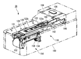
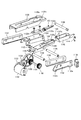
- FIG. 7 is a diagram showing an internal configuration of the staple removing device 1A including the left frame 112, the right frame 114, the front frame 116, and the rear frame 117.
- FIG. 8 is an exploded perspective view of the staple removing device 1A shown in FIG. 7.
- a left frame 112, a right frame 114, a front frame 116, and a rear frame 117 are erected on the outer peripheral portions of the staple pulling mechanism 110 and the paper holding mechanism 160 so as to surround them.
- the left frame 112 is erected on the left side of the staple removal mechanism 110.
- a guide groove 113 extending in the moving direction (longitudinal direction of the housing 100) is formed in the upper portion of the left frame 112 in front of or behind the removing portion 120.
- the guide groove 113 is a first groove 113a for locating the tip portion 122s of the wedge plate 122 of the removing portion 120 waiting at the standby position L1 below the mounting table 102, and the wedge plate 122 of the removing portion 120.
- It includes a second groove 113b for moving the tip portion 122s from the front side of the removal position L2 in a state of protruding from the mounting table 102 until it passes through the removal position L2.
- the position before the removal position L2 includes a position between the standby position L1 and the removal position L2.
- the first groove 113a is formed so that the second drive shaft 138 is closer to the mounting table 102 than the first drive shaft 136 when the tip portion 122s of the removal portion 120 is at least in the standby position L1.
- the first groove 113a extends in parallel along the mounting surface 102a of the mounting table 102 by a predetermined distance from the start end of the moving section of the removing portion 120.
- the second groove 113b is formed at a position slightly lower than the first groove 113a via the stepped portion 113c. That is, the step portion 113c connects the first groove 113a and the second groove 113b.
- the second groove 113b extends in parallel along the mounting surface 102a of the mounting table 102 from the step portion 113c to the end of the moving section of the wedge plate 122.
- the left end portions of the first drive shaft 136 and the second drive shaft 138 of the removal portion 120 are inserted into the guide groove 113.
- the removing portion 120 can be moved along the guide groove 113, and can be moved from the front and the rear along the mounting table 102.
- the right frame 114 is erected on the right side of the staple removal mechanism 110.
- a guide groove 115 extending in the moving direction (longitudinal direction of the housing 100) is formed in the upper part of the right frame 114 in front of or behind the removing portion 120.
- the guide groove 115 is a first groove 115a for locating the tip portion 122s of the wedge plate 122 of the removing portion 120 waiting at the standby position L1 below the mounting table 102, and the wedge plate 122 of the removing portion 120. It includes a second groove 115b for moving the tip portion 122s from the front side of the removal position L2 in a state of protruding from the mounting table 102 until it passes through the removal position L2.
- the second groove 115b is formed so that the second drive shaft 138 is closer to the mounting table 102 than the first drive shaft 136 when the tip portion 122s of the removal portion 120 is at least in the standby position L1.
- the second groove 115b extends in parallel along the mounting surface 102a of the mounting table 102 by a predetermined distance from the start end of the moving section of the removing portion 120.
- the second groove 115b is formed at a position slightly lower than the first groove 115a via the stepped portion 115c.
- the second groove 115b extends in parallel along the mounting surface 102a of the mounting table 102 from the step portion 115c to the end of the moving section of the wedge plate 122.
- the right end portions of the first drive shaft 136 and the second drive shaft 138 of the removal portion 120 are inserted into the guide groove 115.
- the removing portion 120 can move along the guide groove 115, and can move forward and backward along the mounting table 102. That is, the guide groove (guide portion) 115 formed in the frames 112 and 114 (support member) guides the removal portion 120 in a movable manner.
- the front frame 116 is erected on the front side of the staple removal mechanism 110, and the rear frame 117 is erected on the rear side of the paper holding mechanism 160.
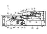
- FIG. 9A is a perspective view showing the operation of the staple removing mechanism 110 at the standby position L1
- FIG. 9B is a perspective view showing the operation of the staple removing mechanism 110 moving to the removal position L2.
- FIG. 10A is a side view of the main part showing the operation of the staple removing mechanism 110 at the standby position L1
- FIG. 10B is a side view of the main part showing the operation of the staple removing mechanism 110 moving to the removal position L2.
- FIG. 11A is a side view showing the operation of the staple removing mechanism 110 at the standby position L1
- FIG. 11B is a side view of a main part showing the operation of the staple removing mechanism 110 of FIG. 11A.
- FIG. 12A is a side view showing the operation of the staple removing mechanism 110 moving to the removal position L2
- FIG. 12B is a side view of a main part showing the operation of the staple removing mechanism 110 of FIG. 12A.
- FIGS. 11 and 12 for convenience, only the left frame 112 side will be described, but the same operation as the left frame 112 side can be adopted for the right frame 114 side on the opposite side.
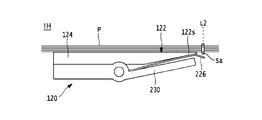
- the wedge plate 122 When the staple removing device 1A is in the standby state, the wedge plate 122 is stopped at the standby position L1 of the housing 100 as shown in FIGS. 9A, 10A and 11A. At this time, the second drive shaft 138 is located in the first groove 113a of the guide groove 113 of the left frame 112, and the first drive shaft 136 is located in the second groove 113b of the guide groove 113 of the left frame 112. Therefore, the mounting portion 122b side of the wedge plate 122 is in a raised state, and the wedge plate main body 122a side including the tip portion 122s of the wedge plate 122 is at a lower position than the mounting portion 122b side. As a result, as shown in FIG.
- the wedge plate main body 122a including the tip portion 122s of the wedge plate 122 is lower than the mounting surface 102a of the mounting base 102. Located in. As a result, when the paper bundle P is placed on the mounting table 102, it is possible to prevent the wedge plate 122 from hitting the paper bundle P and being separated from the mounting table.
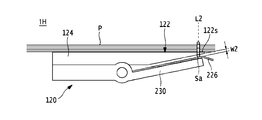
- the first motor 152 When the start switch 106 of the staple removing device 1A is operated, the first motor 152 is driven as shown in FIGS. 9B and 10B, and the driving force of the first motor 152 is the plurality of gears 153a, 153b, 154a, It is transmitted to the pinions 158 and 159 via 154b and 155.
- the pinions 158 and 159 rotate clockwise in FIG. 10B, and the racks 130 and 131 meshing with the pinions 158 and 159 move from the front to the rear along the mounting table 102 so that the wedge plate 122 moves forward. Move backwards from.
- the second drive shaft 138 moves from the first groove 113a of the guide groove 113 of the left frame 112 to the second groove 113b.
- the second drive shaft 138 is parallel to and at the same height as the mounting surface 102a of the mounting base 102 with the first drive shaft 136. Therefore, when the position of the wedge plate 122 on the mounting portion 122b side is lowered, the wedge plate main body 122a side of the wedge plate 122 is lifted (rotated) with the first drive shaft 136 as a fulcrum.
- the upper surface of the wedge plate main body 122a has a structure slightly protruding from the upper surface of the mounting portion 122b, as shown in FIG.
- the tip portion 122s of the wedge plate 122 is the mounting surface of the mounting base 102. It is located above 102a. In other words, the tip portion 122s of the wedge plate 122 rotates with the drive shaft 136 as a fulcrum. In the present embodiment, the wedge plate 122 protrudes from the mounting surface 102a of the mounting table 102 through the opening 102b of the mounting table 102 from the front side of the removing position L2 until it passes through the removal position L2. Move while maintaining. As a result, the tip portion 122s of the wedge plate main body 122a is surely pushed between the paper bundle P and the crown portion Sa.
- FIG. 13A is a perspective view showing the operation of the paper holding mechanism 160 in the standby position
- FIG. 13B is a perspective view showing the operation of the paper holding mechanism 160 moving to the pressing position
- FIG. 14A is a side view of a main part showing the operation of the paper holding mechanism 160 in the standby position
- FIG. 14B is a side view of the main part showing the operation of the paper holding mechanism 160 moving to the pressing position.
- the paper holding plate 176 is stopped at a position at a certain interval from the mounting surface 102a of the mounting table 102.
- the constant interval is an interval at which the lower surface of the paper holding plate 176 does not come into contact with the uppermost layer of the paper bundle P placed on the mounting table 102.
- the second motor 192 When the start switch of the staple removal device 1A is turned on, the second motor 192 is driven. The driving force of the second motor 192 is transmitted to the paper holding pinions 198 and 199 via the gears 193a, 193b, 194a, 194b and 195. Along with this, as shown in FIGS. 13B and 14B, the paper retainer pinions 198 and 199 rotate clockwise, and the paper retainer racks 174 and 175 meshing with the paper retainer pinions 198 and 199 move substantially downward.
- the hold lever 172 rotates counterclockwise with the hold lever shaft 182 as a fulcrum against the elastic force of the return spring 180, and the paper holding plate 176 is placed on the mounting base 102. Moves (descends) in the direction approaching. As a result, the paper bundle P placed on the mounting table 102 is pressed by the paper holding plate 176 with a constant pressing force.
- the second motor 192 is driven in the reverse rotation.
- the paper holding plate 176 moves (rises) in the direction away from the paper bundle P and returns to the standby position shown in FIG. 14A or the like.
- 15A to 15G are side views showing an example of the operation of the staple removing device 1A when the staple S is pulled out from the paper bundle P.
- 16A to 16E are enlarged views of a main part showing an example of the operation of the wedge plate 122 when the staple S is pulled out from the paper bundle P.
- 17A to 17E are diagrams showing the states of the wedge plate 122 and the staple S when the staple S is pulled out from the paper bundle P. In the description of FIG. 15A and the like, for convenience, only the operation on the right side of the staple removing device 1A will be described, but the same operation as on the right side can be adopted for the opposite left side.
- the paper bundle P bound by the staple S is placed on the mounting table 102.
- the user aligns the paper bundle P with the mark indicating the removal position L2 provided on the mounting table 102, and mounts the staple S with the crown portion Sa side facing the mounting table.
- the paper bundle P is bound by staples S.
- the legs Sb and Sb of the staple S penetrate the paper bundle P in the thickness direction of the paper, are bent inward, and bite into the paper surface.
- the first motor 152 is driven.
- the pinion 159 rotates clockwise, so that the removing portion 120 including the rack 131 and the wedge plate 122 moves from the front to the rear.
- the tip portion 122s of the wedge plate main body 122a is positioned below the mounting surface 102a of the mounting base 102, as in the standby position L1. doing.
- the second drive shaft 138 of the removing portion 120 moves to the second groove 115b of the guide groove 115, so that the wedge is shown in FIG. 16B.
- the tip portion 122s of the plate 122 projects from the mounting surface 102a through the opening 102b of the mounting base 102.
- the upper surface of the wedge plate 122 comes into contact with the back surface of the bottom layer of the paper bundle P, and moves from the front to the rear while pressing the paper bundle P.
- the tip of the removing portion 120 waiting at the standby position L1 is located below the mounting table 102, and the tip of the removing portion 120 passes through the removing position from the front of the removing position. It is formed so as to protrude from the mounting table 102.
- the pressing portion 140 rises due to the urging of the tension spring 144, and comes into contact with the crown portion Sa of the paper bundle P that moves from the front to the rear by the pushing force of the wedge plate 122, so that the staple S moves to the rear. regulate.
- the thickness of the wedge plate 122 pushed between the paper bundle P and the crown portion Sa at the removal position is increased in the side view. It gets thicker. Due to the extension of the tension spring 144, the pressing portion 140 is lowered in contact with the wedge plate 122 and the crown portion Sa following the thickness direction of the wedge plate 122. As a result, as shown in FIG. 17C, the crown portion Sa is pushed by the wedge plate 122 in the direction away from the paper bundle P, and the legs Sb and Sb of the staple S bent inward with respect to the paper surface of the paper bundle P. It extends so as to be substantially orthogonal to each other. As shown in FIG.
- the constricted portion 122c of the wedge plate 122 is located at the removal position L2.
- the width dimension D1 of the constricted portion 122c of the wedge plate 122 is narrower than the width dimension D3 between the leg portions Sb and Sb of the staple S that springs back, so that the leg of the staple S The portions Sb and Sb are separated from the side surface of the wedge plate 122, and the staple S falls into the accommodating portion 200.
- the first motor 152 is driven in the reverse rotation.
- the pinion 159 rotates counterclockwise, the removal unit 120 including the rack 131 and the wedge plate 122 moves from the rear to the front along the mounting table 102, and the removal unit 120 moves from the removal position L2 to the standby position. Return to L1.
- the second motor 192 is driven by the reverse rotation.
- the paper holding pinion 199 rotates counterclockwise, and the paper holding rack 175 moves substantially upward, so that the paper holding plate 176 moves away from the mounting table 102 via the hold lever 172. Return to the standby position.
- the wedge plate 122 is configured to move linearly along the mounting table 102, and the tip portion 122s of the wedge plate 122 protrudes from the mounting surface 102a of the mounting table 102. In this state, it is moved from the front of the removal position L2 until it passes through the removal position L2. That is, by providing a certain section in which the tip portion 122s of the wedge plate 122 moves in a state of protruding from the mounting surface 102a, the removal point for removing the staple S can be set as a surface instead of a point.
- the staple S of the paper bundle P in a certain range on the mounting table 102, the staple S can be removed from the paper bundle P, so that the occurrence of defects during the removal operation can be reliably prevented. Can be done. Further, since the staple S may be set in a certain range on the mounting table 102, the burden on the user when setting the paper bundle P on the mounting table 102 can be reduced.
- the tip portion 122s of the wedge plate 122 is moved for a certain section in a state of being projected from the mounting surface 102a of the mounting table 102, the tip portion 122s of the wedge plate 122 is referred to as the paper bundle P. It can be reliably inserted between the crown portion Sa.
- the tip portion 122s of the wedge plate 122 is placed on the mounting surface 102a of the mounting base 102. Since it is positioned downward, it is possible to prevent the paper or the crown portion Sa from being caught by the tip portion 122s of the wedge plate 122 when the paper bundle P is set on the mounting table 102. As a result, it is possible to avoid the occurrence of defects in the paper bundle P due to damage to the paper, and it is possible to improve the operability of the user when the paper bundle P is set on the mounting table 102.
- FIG. 18 is an exploded perspective view of the staple removing device 1B according to the second embodiment.
- a guide groove 213 extending along the mounting surface 102a of the mounting table 102 is formed on the upper part of the left frame 112.
- the guide groove 213 is formed parallel and linearly with respect to the mounting surface 102a from the start end to the end of the moving section including the standby position L1 and the removal position L2 (see FIG. 19B) of the wedge plate 122.
- the right end portions of the first drive shaft 136 and the second drive shaft 138 of the removal portion 120 are inserted into the guide groove 213.
- a guide groove 215 extending along the mounting surface 102a of the mounting table 102 is formed on the upper part of the right frame 114.
- the guide groove 215 is formed parallel and linearly with respect to the mounting surface 102a from the start end to the end of the moving section including the standby position L1 and the removal position L2 of the wedge plate 122.
- the left end portions of the first drive shaft 136 and the second drive shaft 138 of the removal portion 120 are inserted into the guide groove 215. With such a configuration, the removing portion 120 can move forward and backward along the guide grooves 213 and 215 in parallel with the mounting surface 102a of the mounting table 102.
- a step portion 122d is provided between the wedge plate main body 122a and the constricted portion 122c.
- the upper surface of the wedge plate main body 122a projects from the upper surfaces of the mounting portion 122b and the constricted portion 122c via the step portion 122d.
- elongated holes 124a and 124b through which the second drive shaft 138 is inserted are formed.
- the elongated holes 124a and 124b have a long axis extending in the vertical direction.
- the length of the major axis defines the maximum amount of protrusion of the wedge plate 122 that protrudes from the mounting surface 102a of the mounting table 102.
- the front end portion of the blade holder 124 is supported by the second drive shaft 138 and is configured to be movable in the vertical direction along the elongated holes 124a and 124b.
- the tip portion 122s of the wedge plate 122 moves in the vertical direction with the first drive shaft 136 as a fulcrum as the rear end portion of the blade holder 124 moves up and down.
- the wedge plate unit holder 230 is composed of a flat plate formed by bending in a substantially U shape, and is arranged so as to be overlapped on the side surface of the blade holder 124 from below.
- the rack 130 is arranged on the right side of the wedge plate unit holder 230, and the rack 131 is arranged on the left side thereof.
- One end of the wedge plate spring 232 was attached to the attachment portion provided on the lower surface of the front end portion of the blade holder 124, and the other end of the wedge plate spring 232 was provided on the upper surface of the front end portion of the wedge plate unit holder 230. It is attached to the attachment part. The front end of the blade holder 124 and the front end of the wedge plate unit holder 230 are urged to each other in a direction closer to the wedge plate spring 232.
- the spring constant of the wedge plate spring 232 defines the pressing force of the wedge plate 122 projecting upward from the mounting table 102 against the paper bundle P.
- FIG. 19A is an explanatory view of the operation of the wedge plate 122 of the staple removing device 1B at the standby position L1
- FIG. 19B is an enlarged view of a main part of the wedge plate 122 and the mounting table 102 shown in FIG. 19A
- FIG. 20A is an explanatory view of the operation of the wedge plate 122 of the staple removing device 1B that moves to the removal position L2
- FIG. 20B is an enlarged view of a main part of the wedge plate 122 and the mounting table 102 shown in FIG. 20A.
- FIGS. 19A and 20A only the operation on the left side of the staple removing device 1B will be described, but since the operation on the right side is also the same as that on the left side, detailed description thereof will be omitted.
- the tip portion 122s of the wedge plate 122 is located in the standby position L1.
- the upper surface of the wedge plate main body 122a (the tip end side of the wedge plate 122) is pushed down below the mounting table 102 by hitting the back surface of the mounting table 102.
- the rear end portion of the blade holder 124 is pushed up (rotated) along the elongated hole 124b with the first drive shaft 136 as a fulcrum.
- the first motor 152 is driven and the pinion 159 rotates via a plurality of gears 153a and the like.
- the pinion 159 rotates, the removing portion 120 including the rack 131 and the wedge plate 122 moves from the front to the rear, and as shown in FIG. 20B, the stepped portion 122d of the wedge plate 122 is placed on the mounting table 102. It comes off from the back surface of the and moves into the opening 102b.
- the front end portion of the blade holder 124 is pushed down along the elongated hole 124b by the urging of the wedge plate spring 232, while the tip end portion 122s of the wedge plate 122 is pushed up with the first drive shaft 136 as a fulcrum.
- the tip portion 122s of the wedge plate 122 protrudes from the mounting surface 102a of the mounting table 102.
- the tip portion 122s of the wedge plate 122 rotates with the drive shaft 136 as a fulcrum.
- the tip portion 122s of the wedge plate 122 moves from the front side of the removal position L2 until it passes through the removal position L2 in a state of protruding from the mounting surface 102a of the mounting table 102.
- the tip portion 122s of the wedge plate 122 is moved in a fixed section in a state of being projected from the mounting surface 102a of the mounting table 102. Therefore, the tip portion 122s of the wedge plate 122 can be reliably inserted between the paper bundle P and the crown portion Sa. Further, when the tip portion 122s of the wedge plate 122 is in the standby position L1, the tip portion 122s of the wedge plate 122 is positioned below the mounting surface 102a of the mounting table 102, so that the paper bundle P is set on the mounting table 102. At this time, it is possible to prevent the paper or the crown portion Sa from being caught by the tip portion 122s of the wedge plate 122.
- ⁇ Third embodiment> the mechanism for adjusting the moving height of the wedge plate 122 is different from that of the above embodiment. Since the configuration and operation of the other staple removing device 1C are the same as those of the staple removing device 1A of the first embodiment, detailed description of the common parts will be omitted.
- FIG. 21 is a side view of the staple removing device 1C according to the third embodiment.
- a guide groove 313 extending along the mounting surface 102a of the mounting table 102 is formed on the upper part of the left frame 112.
- the guide groove 313 is inclined at a constant angle so as to gradually approach the mounting table 102 from the start end to the end of the moving section of the wedge plate 122. More specifically, in the guide groove 313, the tip portion 122s of the wedge plate 122 is located below the mounting surface 102a of the mounting base 102 when the tip portion 122s of the wedge plate 122 is stopped at the standby position L1. ,
- the tip portion 122s of the wedge plate 122 is formed in a groove shape protruding from the mounting surface 102a of the mounting table 102 when passing through the removal position L2 from the front of the removal position L2.
- the upper part of the right frame 114 is also formed with a guide groove that inclines at a constant angle so as to gradually approach the mounting table 102 from the start end to the end of the moving section of the wedge plate 122. .. Since the guide groove of the right frame 114 is symmetrical with the guide groove 313 of the left frame 112 and has the same configuration, detailed description thereof will be omitted. In this way, in the guide groove 313, the tip of the removing portion 120 waiting at the standby position L1 is located below the mounting table 102, and the tip of the removing portion 120 passes through the removing position from the front of the removing position. It is formed so as to protrude from the mounting table 102.
- FIG. 22A is an explanatory view of the operation of the wedge plate 122 of the staple removing device 1C at the standby position L1
- FIG. 22B is an enlarged view of a main part of the wedge plate 122 and the mounting table 102 shown in FIG. 22A
- FIG. 23A is an explanatory view of the operation of the wedge plate 122 of the staple removing device 1C that moves to the removal position L2
- FIG. 23B is an enlarged view of a main part of the wedge plate 122 and the mounting table 102 shown in FIG. 23A.
- FIGS. 22A and 23A only the operation on the right side of the staple removing device 1C will be described, but since the operation on the left side is also the same as that on the right side, detailed description thereof will be omitted.
- the tip portion 122s of the wedge plate 122 When the staple removing device 1C is in the standby position, as shown in FIGS. 22A and 22B, the tip portion 122s of the wedge plate 122 is located in the standby position L1, and the second drive shaft 138 of the removing portion 120 is the left frame 112. It is located at the starting end of the guide groove 113. In this case, the tip portion 122s of the wedge plate 122 is located below the mounting surface 102a of the mounting table 102. As a result, when the paper bundle P is placed on the mounting table 102, it is possible to prevent the wedge plate 122 from hitting the paper bundle P and causing a problem.
- the first motor 152 When the staple removal device 1C is activated, the first motor 152 is driven as shown in FIGS. 23A and 23B. The driving force of the first motor 152 is transmitted to the pinion 158 via the gear 153a and the like. Along with this, the pinion 158 rotates clockwise to move the rack 130 from the front to the rear, and the wedge plate 122 to move from the front to the rear along the guide groove 313 of the left frame 112. The wedge plate 122 gradually moves toward the mounting table 102 along the guide groove 313, and the tip portion 122s protrudes from the mounting table 102. In another embodiment 2, the tip portion 122s of the wedge plate 122 protrudes from the mounting surface 102a of the mounting table 102 from the front of the removing position L2, and maintains the protruding state until it passes through the removing position L2.
- the tip portion 122s of the wedge plate 122 is moved in a fixed section in a state of protruding from the mounting surface 102a of the mounting table 102. Therefore, the tip portion 122s of the wedge plate 122 can be reliably inserted between the paper bundle P and the crown portion Sa. Further, when the tip portion 122s of the wedge plate 122 is in the standby position L1, the tip portion 122s of the wedge plate 122 is positioned below the mounting surface 102a of the mounting table 102, so that the paper bundle P is set on the mounting table 102. At this time, it is possible to prevent the paper or the crown portion Sa from being caught by the tip portion 122s of the wedge plate 122.
- FIG. 24 is an exploded perspective view of the staple removing device 1D according to the fourth embodiment.
- Guide pin mounting portions 410, 411 to which the guide pins 420, 421 are mounted are provided on the lower surface of the mounting table 102 on the rear end side.
- the guide pin mounting portions 410 and 411 are arranged at predetermined intervals in the width direction, specifically, at substantially the same interval as between the left frame 112 and the right frame 114.
- the guide pin mounting portion 410 is formed with a pin opening 410a
- the guide pin mounting portion 411 is formed with a pin opening 411a.
- the pin openings 410a and 411a are formed of elongated holes having a long axis extending in the vertical direction.
- Shaft mounting portions 408 and 409 through which the fulcrum shaft 418 is inserted are provided on the lower surface on the rear end side of the mounting base 102.
- the shaft mounting portions 408 and 409 are arranged at predetermined intervals in the width direction, specifically, at substantially the same interval as between the left frame 112 and the right frame 114.
- the shaft mounting portion 408 is formed with a shaft opening 408a
- the shaft mounting portion 409 is formed with a shaft opening 409a.
- a recess 112d in which the mounting base spring 416 is arranged is provided at a position facing the guide pin mounting portion 410 on the rear end side of the left frame 112.
- a recess 114d in which the mounting base spring 417 is arranged is provided at a position facing the guide pin mounting portion 411 on the rear end side of the right frame 114.
- the guide grooves 413 formed in the left frame 112 and the guide grooves 415 formed in the right frame 114 have the same configurations and functions as those of the guide grooves 213 and 215 of the second embodiment. Omit.
- the guide pin 420 is inserted into the pin opening 410a on the front end side of the mounting table 102 from the outside, and is attached to the opening 112e of the left frame 112 arranged inside the guide pin 420.
- the guide pin 421 is inserted into the pin opening 411a on the front end side of the mounting table 102 from the outside, and is attached to the opening 114e of the right frame 114 arranged inside the guide pin 421.
- a mounting table spring 416 is arranged between the recess 112d of the left frame 112 and the lower surface of the mounting table 102.
- the mounting base spring 417 is arranged between the recess 114d of the right frame 114 and the lower surface of the mounting base 102.
- the fulcrum shaft 418 is inserted through the opening 112f of the left frame 112, the shaft openings 408a and 409a of the mounting table 102, and the opening 114f of the right frame 114.
- the mounting table 102 can move in the vertical direction along the pin openings 410a and 411a on the rear end side with the fulcrum shaft 418 on the front end side as the fulcrum. That is, the mounting table 102 moves in the vertical direction relative to the tip portion 122s of the wedge plate 122 with the fulcrum shaft 418 as the fulcrum within the range of the length of the elongated holes of the pin openings 410a and 411a.
- FIG. 25A is an explanatory view of the operation of the wedge plate 122 of the staple removing device 1D at the standby position L1
- FIG. 25B is an enlarged view of a main part of the wedge plate 122 and the mounting table 102 shown in FIG. 25A
- FIG. 26A is an explanatory view of the operation of the wedge plate 122 of the staple removing device 1D that moves to the removal position L2
- FIG. 26B is an enlarged view of a main part of the wedge plate 122 and the mounting table 102 shown in FIG. 26A.
- FIGS. 25A and 26A only the operation on the right side of the staple removing device 1C will be described, but since the operation on the left side is also the same as that on the right side, detailed description thereof will be omitted.
- the paper retainer plate 176 of the paper retainer mechanism 160 is stopped at the standby position at a certain interval from the mounting table 102.
- the mounting table 102 is urged upward by the mounting table spring 416, so that the tip portion 122s of the wedge plate 122 is located below the mounting table 102.
- the second motor 192 is driven, and the paper holding plate 176 descends toward the mounting table 102 via the gear 153a or the like, and is placed on the mounting table 102.
- the paper bundle P is pressed by the paper holding plate 176.
- the mounting table 102 is pressed by the paper holding plate 176 via the paper bundle P, so that the mounting table spring 416 is compressed and the mounting table 102 has an elongated pin opening. It is pushed down along the portion 410a (see FIG. 24) and the like. As a result, the tip portion 122s of the wedge plate 122 protrudes from the mounting surface 102a of the mounting table 102.
- the mounting table 102 is restricted from moving downward by contacting the flanges formed at the upper ends of the left frame 112 and the right frame 114. Therefore, by adjusting the height of the flange, the maximum amount of protrusion of the tip portion 122s of the wedge plate 122 can be adjusted. Further, the spring constants and sizes of the mounting base springs 416 and 417 may be adjusted.
- the tip portion 122s of the wedge plate 122 is moved in a fixed section in a state of being projected from the mounting surface 102a of the mounting table 102. Therefore, the tip portion 122s of the wedge plate 122 can be reliably inserted between the paper bundle P and the crown portion Sa. Further, when the tip portion 122s of the wedge plate 122 is in the standby position L1, the tip portion 122s of the wedge plate 122 is positioned below the mounting surface 102a of the mounting table 102, so that the paper bundle P is set on the mounting table 102. At this time, it is possible to prevent the paper or the crown portion Sa from being caught by the tip portion 122s of the wedge plate 122.
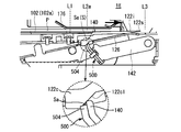
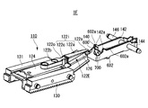
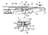
- ⁇ Modification 1-1> In the staple removing device 1E according to the modified example 1-1, an embodiment shown in FIG. 1A or the like is provided in that a crown support portion 500 for supporting the crown portion Sa is provided between the staple plate S and the wedge plate 122E when the staple S is removed. Is different from.
- the components that are substantially the same as the staple removing device 1A and the like are designated by the same reference numerals, so that duplicate description will be omitted.
- FIG. 27A is an exploded perspective view of the staple removing device 1E according to the modified example 1-1
- FIG. 27B is a perspective view of the staple removing device 1E.
- FIG. 28 is a side view of the wedge plate 122E according to the modified example 1-1.
- FIG. 29A is a side view of the crown support portion 500 and the pressing portion 140 according to the modified example 1-1
- FIG. 29B is a diagram illustrating a state in which the crown portion Sa is supported by the crown supporting portion 500 and the pressing portion 140.
- the staple removing device 1E can place the paper bundle P bound by the staples S including the crown portion Sa and the pair of leg portions Sb with the crown portion Sa facing downward.
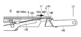
- the mounting table 102 (see FIG. 1A) and the tip portion 122s are removed from the standby position (first position) L1 along the mounting table 102 via the removal start position (second position) L2a (third position). It is movable to L3, and when it moves from the standby position L1 to the removal start position L2a, it is inserted between the paper bundle P and the staple S, and further moves from the removal start position L2a toward the removal completion position L3.
- An inclined portion 122i that starts pulling out the staple S from the bundle P, and a crown portion Sa of the staple S that is pulled out from the paper bundle P by the inclined portion 122i and is engaged (hooked or wound) with the inclined portion 122i.
- the pressing portion (regulating portion) 140 that regulates the movement of the staple S together with the inclined portion 122i in the direction of the removing completion position L3 by contacting the staple S from the removal complete position L3 side, and the pressing portion 140 restrict the movement of the staple S.
- a crown support portion 500 located below the crown portion Sa of the staple S is provided.
- the standby position L1 is the position of the tip portion 122s at the initial position where the inclined portion 122i is stopped before starting the removal operation.
- the removal start position L2a is a position where the tip portion 122s of the inclined portion 122i is inserted between the paper bundle P on the mounting table 102 and the staple S (crown portion Sa), in other words, on the mounting table 102. This is the position of the staple S (crown portion Sa) of the paper bundle P placed on the paper bundle P.
- the removal completion position L3 is the position of the tip portion 122s of the inclined portion 122i when the staple S is completely removed from the paper bundle P by the inclined portion 122i (the staple S is completely separated from the paper bundle P).
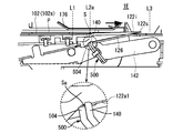
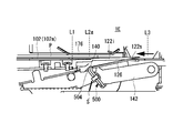
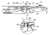
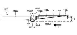
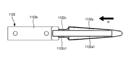
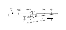
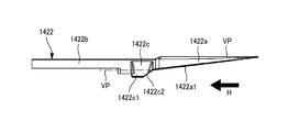
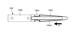
- the wedge plate 122E includes an inclined portion 122i and a mounting portion 122b.
- the inclined portion 122i has a wedge plate main body 122a and a constricted portion 122c, includes a base end portion 122o and a tip portion 122s, and is inclined so that the thickness becomes thinner from the base end portion 122o to the tip end portion 122s.
- the inclined surface 122ac has a first inclined surface 122a1 and a second inclined surface 122c1.
- the inclined portion 122i is located between the removal start position L2a and the removal completion position L3, and faces the inclined surface 122ac while the tip portion 122s moves from the removal start position L2a to the removal completion position L3.
- the first inclined surface 122a1 is a surface inclined at an angle ⁇ 1 with respect to a virtual surface (horizontal plane) VP parallel to the upper surface of the wedge plate main body 122a.
- the second inclined surface 122c1 is a surface inclined at an angle ⁇ 2 with respect to the virtual surface (horizontal plane) VP parallel to the upper surface of the wedge plate main body 122a.
- the first inclined surface 122a1 and the second inclined surface 122c1 are each composed of continuous surfaces, but are not necessarily limited to continuous surfaces, and are intermittent surfaces, specifically, a plurality of surfaces having different angles. It can also be configured with an inclined surface of.
- the second inclined surface 122c1 of the constricted portion 122c with respect to the virtual surface VP is larger than the first inclined surface 122a1 of the wedge plate main body 122a with respect to the virtual surface VP.
- the angle ⁇ 2 formed by the virtual surface VP and the second inclined surface 122c1 is configured to be larger than the angle ⁇ 1 formed by the virtual surface VP and the first inclined surface 122a1 of the wedge plate main body 122a.
- the angle ⁇ 1 of the first inclined surface 122a1 of the wedge plate body 122a is small and long in the front-rear direction. Is set longer.
- the leg portion Sb of the staple S is completely or almost pulled out from the paper bundle P, and the load applied to the constricted portion 122c is small, so that the first of the constricted portions 122c
- the angle ⁇ 2 of the inclined surface 122a1 is set to be large and short in the front-rear direction.
- the first inclined surface 122a1 and the second inclined surface 122c1 are formed by different inclination angles. Therefore, as shown in FIG. 27A, the first inclined surface 122a1 has the first inclined surface.
- the crown portion Sa is supported by the linear crown holder 126 arranged along the 122a1.
- the crown holder 126 cannot support the crown portion Sa on the second inclined surface 122c1.
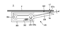
- the crown support portion 500 is provided so that a stable posture can be maintained on the inclined portion 122i until the staple S pulled out from the paper bundle P falls into the accommodating portion 200. ing.
- the crown support portion 500 is arranged at a position adjacent to the removal start position L2a side (left side in the drawing in FIG. 30A) with respect to the pressing portion 140, and is a crown portion of the staple S. Sa can be supported from the lower side.
- the crown support portion 500 has a mounting portion 502 fixed to the pressing portion 140 and a support portion 504 capable of contacting the crown portion Sa of the staple S.
- the mounting portion 502 is composed of a flat plate having a substantially rectangular shape in a plan view, and is mounted on the front surface of the holding portion 140 on the removal start position L2a side by a screw or the like. In the present embodiment, the mounting portion 502 is mounted in contact with the pressing portion 140, but the present invention is not limited to this. For example, if the gap is less than the thickness of the crown portion Sa (diameter of the staple S), the mounting portion 502 may be arranged apart from the pressing portion 140.
- the support portion 504 projects convexly from the upper end portion of the mounting portion 502 toward the wedge plate 122E side, and the tip end side thereof is configured in a tapered shape.
- the tip end side of the support portion 504 By forming the tip end side of the support portion 504 into a tapered shape, the tip end side can be supported in a state of being abutted against the crown portion Sa, so that the posture of the staple S can be stabilized.
- the shape of the tip side of the support portion 504 may be, for example, a configuration in which a plurality of tapered shapes are provided along the longitudinal direction of the crown portion Sa, or an arc shape or a rectangular shape. You may.
- the support portion 504 may be arranged at a predetermined interval with respect to the crown portion Sa while the pressing portion 140 restricts the staple S from moving to the removal completion position L3 side as the inclined portion 122i advances. .. That is, when the posture of the staple S during the removal operation is unstable, for example, when only one leg Sb of the staple S caught on the inclined portion 122i comes off and the staple S rotates, the tip side of the support portion 504 becomes a crown. It may be configured so as to abut against the portion Sa so that the posture of the staple S can be stabilized.
- the predetermined interval is an interval at which at least the tip end side of the support portion 504 can contact and support the crown portion Sa even when the staple S caught on the inclined portion 122i is in an unstable posture. is there.
- the tip portion of the support portion 504 enables the crown portion Sa to be supported between the support portion 504 and the inclined portion 122i, and holds the crown portion Sa that is about to move to the removal completion position L3 side on the front surface of the holding portion 140.
- the crown portion Sa is formed at a position lower than the tip surface 140a of the pressing portion 140 by at least the thickness T1 of the crown portion Sa.
- the length of the support portion 504 in the front-rear direction is composed of the thickness T2 or more of the crown portion Sa.
- the tip side of the support portion 504 of the crown support portion 500, the front surface of the pressing portion 140, and the lower surface of the inclined portion 122i (first inclined surface 122a1) are formed by the crown portion Sa when the staple S is removed. Can be reliably supported.
- the length of the support portion 504 in the front-rear direction is not limited to the thickness T2 or more of the crown portion Sa, and may be less than the thickness T2 of the crown portion Sa as long as a part of the crown portion Sa can be supported.
- a position regulating portion 506 projecting toward the pressing portion 140 is provided.
- the position regulating portion 506 engages with the lower end portion of the pressing portion 140, and functions as a positioning portion when the mounting portion 502 and the supporting portion 504 are attached to the pressing portion 140.
- FIG. 29C is a side view of the case where the crown support portion 500 and the pressing portion 140 are composed of one component. As shown in FIG. 29C, the upper end side of the pressing portion 140 is cut out so as to have a tapered shape shown in FIG. 27A, for example, so that the crown supporting portion 500 can function as supporting the crown portion Sa.
- FIGS. 30A to 30F are side views showing the operation of the staple removing device 1E when the staple S is pulled out from the paper bundle P.
- the paper bundle P When the paper bundle P is placed on the mounting table 102 by the user and the start switch 106 (see FIG. 1A) of the staple removing device 1E is pressed, the paper bundle P is moved by the paper holding plate 176 as shown in FIG. 30A. It is pressed and the paper bundle P is pressed against the mounting table 102.
- the pressing portion 140 abuts on the surface on the removal complete position L3 side of the crown portion Sa that moves from the front to the rear by the pushing force of the inclined portion 122i, and the staple S moves to the rear removal complete position L3 side together with the wedge plate body 122a. Regulate what you do. That is, the holding portion 140 does not move the staple S from the removal start position L2a to the removal completion position L3 side due to the sliding operation of the wedge plate main body 122a inserted between the staple S and the paper bundle P during the removal operation. As described above, the crown portion Sa is pressed from the removal completion position L3 side. Further, in this modification, the support portion 504 of the crown support portion 500 abuts on the lower surface of the crown portion Sa, so that the posture stability of the staple S is ensured.
- the thickness of the inclined portion 122i including the first inclined surface 122a1 inserted between the paper bundle P and the crown portion Sa becomes thicker, as shown in FIG. 30C, the pressing portion 140 and the crown portion 140 and the crown.
- the support portion 500 is lowered by the tension spring 144 following the thickness direction of the inclined portion 122i in a state of being in contact with the inclined portion 122i and the crown portion Sa.
- the crown portion Sa is supported by the support portion 504 and the pressing portion 140 of the crown support portion 500.
- the staple S when the staple S is located on the second inclined surface 122c1 of the inclined portion 122i, the staple S is not supported by the crown holder 126, but the crown portion is provided by the support portion 504 and the holding portion 140 of the crown support portion 500. The state in which Sa is supported is maintained, and tilting, rotation, etc. of the staple S are prevented.
- the tip portion 122s moves to the removal completion position L3 as the wedge plate 122E advances and the staple S is located at the constricted portion 122c having the thickest thickness in the inclined portion 122i, the second portion Similar to the inclined surface 122c1, the staple S is not supported by the crown holder 126, but the crown portion Sa is supported by the support portion 504 and the pressing portion 140 of the crown support portion 500, and the posture stability of the staple S is ensured. ..
- the wedge plate 122E including the inclined portion 122i moves from the rear to the front of the removal completion position L3 along the mounting table 102 and returns to the standby position L1.
- the staple S moves forward with respect to the crown support portion 500, so that the crown portion Sa is disengaged from the support of the support portion 504.
- the staple S falls into the accommodating portion 200.
- the crown portion Sa of the staple S can be supported by the crown support portion 500 until just before the staple S falls, so that the posture stability of the staple S can be ensured until just before the staple S is dropped.
- the staple S can be reliably dropped into the accommodating portion 200, and the staple S can be prevented from scattering into the staple removing device 1E.
- the staple contact portion for peeling the staple S remaining on the inclined portion 122i of the wedge plate 122E from the inclined portion 122i when the staple S is removed from the paper bundle P It differs from the embodiment shown in FIG. 1A and the like in that 600 is provided.
- the components that are substantially the same as the staple removing device 1A and the like are designated by the same reference numerals, so that duplicate description will be omitted.
- the duplicate description is omitted by assigning the same reference numerals to the components common to the modified example 1-1. ..
- FIG. 31A is an exploded perspective view of the staple removing device 1F according to the modified example 1-2
- FIG. 31B is a perspective view of the staple removing device 1F
- FIG. 32 is a side view of the staple contact portion 600 (contact portion) and the pressing portion 140 according to the modified example 1-2.
- the staple removing device 1F includes a mounting table 102 on which a paper bundle P bound by staples S including a crown portion Sa and a pair of leg portions Sb is placed, and a tip portion 122s. Is movable along the mounting table 102 between the standby position (first position) L1 and the removal completion position (third position) L3 via the removal start position (second position) L2a, and the tip portion 122s. Is inserted between the paper bundle P and the staple S when it moves from the standby position L1 to the removal start position L2a, and further moves from the removal start position L2a toward the removal completion position L3 to move the paper bundle P to the staple S.
- the first portion is located between the inclined portion 122i including the wedge plate main body 122a for starting the pulling out and the standby position L1 and the removal start position L2a, and while the tip portion 122s moves from the removal completion position L3 to the removal start position L2a.
- a staple contact portion 600 that faces the inclined surface 122a1 and is pulled out from the paper bundle P by the inclined portion 122i and abuts on the crown portion Sa of the staple S that is engaged with the inclined portion 122i from the standby position L1 side is provided.
- the staple removing device 1F keeps the staple contact portion 600 within a predetermined value from the first inclined surface 122a1 and the second inclined surface 122c1 while the tip portion 122s moves from the removal completion position L3 to the removal start position L2a.
- a holding member (holding portion) 602 that movably supports the staple contact portion 600 so as to hold the staple contact portion 600 is provided.
- the staple removal device 1F is located between the removal start position L2a and the removal completion position L3, and faces the inclined surface 122ac while the tip portion 122s moves from the removal start position L2a to the removal completion position L3.
- the staple S is pulled out from the paper bundle P by the inclined portion 122i and abuts on the crown portion Sa of the staple S engaged with the inclined portion 122i from the removal complete position L3 side, so that the staple S is brought into contact with the inclined portion 122i in the removal complete position L3 direction.
- a holding unit (regulating unit) 140 for restricting movement is provided.
- the staple contact portions 600 are arranged to face each other in front of the standby position L1 side of the pressing portion 140 with a predetermined interval, and are arranged from the front upper end portion of the holding member 602 to the inclined portion 122i side. It projects convexly toward.
- the staple contact portion 600 is urged toward the inclined portion 122i by the tension spring 604 so that the staple plate 122E can come into contact with the lower surface of the inclined portion 122i. As shown in FIG.
- the staple contact portion 600 is inclined in a direction approaching the pressing portion 140 side toward the inclined portion 122i side (upper side), and the staple contact portion 600 is retracted when the wedge plate 122E is retracted. It is configured so that the staple S remaining engaged with the 600 can maintain the engaged state with the crown portion Sa until it separates from the inclined portion 122i.
- the staple contact portion 600 does not necessarily have to be tilted, and may be extended in the vertical (vertical) direction, for example.
- the height of the staple contact portion 600 is set to a position slightly lower than that of the pressing portion 140, for example, in consideration of the inclination angle of the first inclined surface 122a1 on the lower surface side of the inclined portion 122i.
- the width of the staple contact portion 600 is selected to be a length that can be contacted with the crown portion Sa that moves from the rear to the front as the wedge plate 122E retracts and can be inserted into the groove portion 126a of the crown holder 126. Will be done.
- the holding member 602 is formed of a flat plate processed into a substantially U shape in a top view, and is arranged so as to abut against the outside of the holding holder 142.
- the rear end side of the holding member 602 is rotatably supported by a shaft 146.
- One end of the tension spring 604 is attached further behind the shaft 146 of the holding member 602.
- the other end of the tension spring 604 is attached, for example, to the left frame 112 (see FIG. 8).
- a pair of convex portions 602a that can come into contact with the support portion 128b of the holder 128 are provided at the front upper end portion of the holding member 602.
- the area surrounded by the pressing portion 140, the staple contact portion 600, and the holding member 602 is formed when the staple S peeled off from the inclined portion 122i by the staple contact portion 600 falls.
- the opening 700 is located above the accommodating portion 200 (see FIG. 3).
- the staple S pulled out from the paper bundle P by advancing the wedge plate 122E falls into the accommodating portion 200 through the opening 700 without being caught by the inclined portion 122i. .. That is, the staple S falls into the accommodating portion 200 without using the staple contact portion 600.
- FIGS. 33A to 33G are side views showing the operation of the staple removing device 1F when the staple S is pulled out from the paper bundle P.
- the convex portion 142a of the holding holder 142 and the convex portion 602a of the holding member 602 come off from the holder 128, and the holding portion 140 and the staple contact with each other.
- the portion 600 is urged toward the upper inclined portion 122i by the tension springs 144 and 604.
- the pressing portion 140 abuts on the rear surface on the removal complete position L3 side of the crown portion Sa that moves from the front to the rear by the pushing force of the wedge plate 122E, and the staple S together with the wedge plate main body 122a is on the rear removal complete position L3 side. Regulate moving to.
- the staple contact portion 600 abuts on the first inclined surface 122a1 on the lower surface side of the inclined portion 122i.
- the pressing portion 140 and the staple contact portion 600 are pulled.
- the springs 144 and 604 lower the inclined portion 122i in contact with the inclined portion 122i and the crown portion Sa in the thickness direction of the inclined portion 122i.
- the leg portion Sb rises with respect to the paper bundle P and is pulled out from the paper bundle P, and as shown in FIG. 33D, the tip portion 122s of the inclined portion 122i
- the staple S is moved to the removal completion position L3 and the staple S is located at the constricted portion 122c which is the thickest portion of the inclined portion 122i, the removal of the staple S from the paper bundle P is completed.
- the staple S remains caught on the side surface of the inclined portion 122i due to the springback of the leg portion Sb, and does not fall into the accommodating portion 200.
- the wedge plate 122E including the inclined portion 122i in the state where the staple S is caught moves from the rear removal completion position L3 to the front standby position L1 along the mounting table 102.
- the staple contact portion 600 located in front of the staple S is in the standby position on the crown portion Sa of the staple S that is pulled out from the paper bundle P by the wedge plate 122E and remains engaged with the constricted portion 122c, for example. Contact from the L1 side.
- the removal completion position L3 It may be configured to abut in a part of the section between the removal start position L2a.
- the staple S is held by the constricted portion 122c of the inclined portion 122i by the springback of the legs Sb and Sb of the staple S expanded by inserting the wedge plate 122E. It became easy to attach, and the staple S sometimes did not fall from the inclined portion 122i. In the same case, even when the center of the inclined portion 122i in the left-right direction and the center of the crown portion Sa in the longitudinal direction are set to be misaligned, the staple S is irregularly deformed and the wedge plate 122E is set. In some cases, the staple S did not fall from.
- the staple S pulled out from the paper bundle P remains on the inclined portion 122i, the crown portion Sa is caught on the staple contact portion 600 when the wedge plate 122E is retracted. Therefore, the staple S can be reliably peeled off from the inclined portion 122i and removed. As a result, clogging of the staple S can be prevented, and the occurrence of defects during the removal operation can be suppressed.
- the staple contact portion 600 is necessarily brought into contact with the lower surface of the inclined portion 122i.
- the staple contact portion 600 may be arranged at a predetermined interval (predetermined value) with respect to the lower surface of the inclined portion 122i.
- the predetermined interval is, for example, an interval at which the staple contact portion 600 can be hooked on the crown portion Sa of the staple S remaining on the inclined portion 122i when the wedge plate 122E returns to the standby position L1.
- the staple removing device 1G according to the modified example 1-3 is configured by combining the crown support portion 500 of the modified example 1-1 and the staple contact portion 600 of the modified example 1-2. It has substantially the same functional configuration as the staple removing device 1A according to the embodiment shown in FIG. 1A and the like, the staple removing device 1E according to the modified example 1-1, and the staple removing device 1F according to the modified example 1-2. Duplicate explanations will be omitted by assigning the same reference numerals to the components.
- FIG. 34A is an exploded perspective view of the staple removing device 1G according to the modified example 1-3
- FIG. 34B is a perspective view of the staple removing device 1G.
- the staple removing device 1G holds the mounting base 102, the wedge plate 122E including the inclined portion 122i, the holding portion 140, the crown support portion 500, and the staple contact portion 600.
- the crown support portion 500 is located below the crown portion Sa of the staple S while the pressing portion 140 regulates the movement of the staple S.
- the crown support portion 500 has a mounting portion 502 fixed to the pressing portion 140 and a support portion 504 capable of contacting the crown portion of the staple S.
- the mounting portion 502 is formed of a flat plate having a substantially rectangular shape in a plan view, and is mounted on the front surface of the holding portion 140 by a screw or the like.
- the support portion 504 projects convexly from the upper end portion of the mounting portion 502 toward the inclined portion 122iE side, and the tip end side thereof is formed in a tapered shape.
- the staple contact portion 600 is located between the standby position L1 and the removal start position L2a, and while the tip portion 122s moves from the removal completion position L3 to the removal start position L2a. It faces the first inclined surface 122a1 and is pulled out from the paper bundle P by the inclined portion 122i, and comes into contact with the crown portion Sa of the staple S engaged with the inclined portion 122i from the standby position L1 side.
- the staple contact portion 600 is arranged to face the holding portion 140 and the crown support portion 500 at predetermined intervals, and protrudes from the front upper end portion of the holding member 602 toward the inclined portion 122i side.
- the area surrounded by the crown support portion 500, the staple contact portion 600, and the holding member 602 is an opening 700 through which the staple S peeled off from the inclined portion 122i at the staple contact portion 600 passes when falling. ..
- the tip end side of the crown holder 126 is in contact with the lower surface of the wedge plate 122 due to the bias of the spring 125, and the tip end portion of the wedge plate 122.
- the 122s and the tip end side of the crown holder 126 are in a closed state.
- the crown portion Sa of the staple S is inserted between the wedge plate 122 and the crown holder 126, as shown in FIG. 35B.
- the tip end side of the crown holder 126 is pushed away from the wedge plate 122 against the elastic force of the spring 125, and is opened by the opening amount W1 with respect to the tip end portion 122s of the wedge plate 122.
- the removing portion 120 further moves from the front to the rear, as shown in FIG. 35C, the thickness of the wedge plate 122 between the paper bundle P and the crown portion Sa gradually increases, and the leg portion Sb of the staple S becomes thicker. Stands away from the paper surface of the paper bundle P.
- the load of the spring 125 is set according to the staple S having a small wire diameter, the staple S can be slid while being sandwiched between the wedge plate 122 and the crown holder 126, and can be slid together with the wedge plate 122 from the front. It does not move backwards.
- 36A to 36C are schematic views showing an operation example of the removing unit 120 when the staple S is removed from the paper bundle P bound by the (thick) staple S having a large wire diameter.
- the wedge plate 122 and the blade holder 124 are shown integrally for convenience.
- the tip end side of the crown holder 126 is in contact with the lower surface of the wedge plate 122 due to the urging of the spring 125, and the tip end portion 122s of the wedge plate 122 and the tip end side of the crown holder 126 are closed. Is.
- the crown portion Sa of the staple S is inserted between the wedge plate 122 and the crown holder 126, as shown in FIG. 36B.
- the tip end side of the crown holder 126 is pushed in a direction away from the wedge plate 122 against the elastic force of the spring 125, and is opened by the opening amount W2 with respect to the tip end portion 122s of the wedge plate 122.
- the opening amount W2 corresponds to the preset value set in advance, and is an opening amount that can be held with an optimum load without opening the crown holder 126 too much when, for example, a staple S having a large wire diameter is inserted.
- the regulating portions 127a and 127b are in contact with the lower surface 124c of the blade holder 124, and the tip side of the crown holder 126 is not opened by the opening amount W2 or more. Is regulated by.
- the load of the spring 125 is set according to the staple S having a small wire diameter, and the crown holder 126 is prevented from opening more than the set value by using the regulating portions 127a and 127b. It is configured in.
- the crown holder 126 can prevent the crown holder 126 from opening more than the set value by the regulating portions 127a and 127b, and the crown portion Sa can be prevented by the constant load of the crown holder 126.
- the crown portion Sa can be pressed by the optimum load by the crown holder 126 by the spring 125 set according to the staple S having a small wire diameter. As a result, it is possible to prevent defective removal such as the paper being torn due to the crown portion Sa being dragged by moving from the front to the rear of the wedge plate 122 or the like. Therefore, according to the present embodiment, even when various types of staples S such as staples S having a large wire diameter and staples S having a small wire diameter are used, the staples S can be reliably removed from the paper bundle P. .. Further, since it is not necessary to change the removal operation or the removal mechanism according to the type of staple S, it is possible to improve the efficiency of the removal operation and reduce the cost of the apparatus.
- ⁇ Modification 2-1> the configuration of the crown holder 226 and the like are different from the configuration and the like of the crown holder 126 of the first embodiment. Since other configurations and operations of the staple removing device 1H of the modified example 2-1 are the same as those of the first embodiment, detailed description thereof will be omitted.
- FIG. 37A to 37C are schematic views of a removing portion 120 including a crown holder 226 of the staple removing device 1H according to the modified example 2-1.
- the wedge plate 122 and the blade holder 124 are shown integrally for convenience. Further, in the following, it is assumed that the staple S having a large wire diameter is used and the opening amount W2 is set to the wire diameter of the staple S used.
- the removing portion 120 constituting the staple removing device 1H includes a wedge plate 122, a blade holder 124, a crown holder 226, and a crown holder stopper 230.
- the crown holder 226 is composed of, for example, a leaf spring, and holds the crown portion Sa inserted between the wedge plate 122 and the crown holder 226.
- the base end portion of the crown holder 226 is attached to a substantially central portion of the crown holder stopper 230.
- the tip end side of the crown holder 226 is urged toward the wedge plate 122 side and is pressed against the lower surface of the wedge plate 122.
- the load of the crown holder 226 is set according to the staple S having a smaller wire diameter among the staples S to be used.
- the crown holder stopper 230 is arranged below the crown holder 226, and regulates the opening amount of the crown holder 226 so that the crown holder 226 does not open more than the set value with respect to the wedge plate 122.
- the tip end side of the crown holder 226 is arranged at a certain distance from the lower surface of the wedge plate 122 facing the crown holder 226.
- the constant interval is an interval obtained by adding the thickness of the crown holder 226 and the wire diameter of the crown portion Sa.
- the base end side of the crown holder stopper 230 is in contact with the lower surface of the blade holder 124.
- the tip end side of the crown holder 226 is pressed against the lower surface of the wedge plate 122 before the wedge plate 122 of the removal portion 120 reaches the removal position L2.
- the tip portion 122s of the wedge plate 122 is inserted between the paper bundle P and the crown portion Sa of the staple S. ..
- the crown holder 226 moves in a direction away from the lower surface of the wedge plate 122 against the elastic force, and opens by an opening amount W2 according to the wire diameter of the crown portion Sa.
- the tip end side of the crown holder 226 does not open more than the opening amount W2.
- the opening amount of the crown holder 226 is regulated by the crown holder stopper 230, so that the open state is maintained by the opening amount W2. ..
- the modification 2-1 can also exert the same effect as that of the first embodiment. That is, according to the modification 2-1 even when various types of staples S such as a staple S having a large wire diameter and a staple S having a small wire diameter are used, the staple S is surely removed from the paper bundle P. Can be done.
- ⁇ Modification 2-2> the configuration of the crown holder 326 and the like are different from the configuration and the like of the crown holder 126 of the first embodiment. Since other configurations and operations of the staple removing device 1I of the modified example 2-2 are the same as those of the first embodiment, detailed description thereof will be omitted.
- FIGStructure example of removal unit 120 including crown holder 326 and the like] 38A to 38C are schematic views of a removing portion 120 including a crown holder 326 of the staple removing device 1I according to the modified example 2-2.
- a staple S having a large wire diameter is used, and the opening amount W2 is set corresponding to the wire diameter of the staple S used.
- the removing unit 120 constituting the staple removing device 1I includes a wedge plate 122, a wedge plate holder 300, and a crown holder 326.
- the wedge plate holder 300 is a box body whose rear side is open, and accommodates each of the proximal end side of the wedge plate 122 and the proximal end side of the crown holder 326.
- a compression spring 302 is arranged between a portion of the crown holder 326 near the first drive shaft 136 and the inner bottom surface of the wedge plate holder 300.
- the load of the compression spring 302 is set according to the staple S having a smaller wire diameter among the staples S used.
- the crown holder 326 is urged toward the wedge plate 122 by the compression spring 302 and pressed against the lower surface of the wedge plate 122.
- a shaft opening 326a through which the first drive shaft 136 is inserted is formed at a substantially intermediate position in the longitudinal direction of the crown holder 326.
- the shaft opening 326a is composed of an elongated hole having a long axis in the vertical direction. As a result, the crown holder 326 can move vertically with respect to the first drive shaft 136 along the shaft opening 326a.
- a fulcrum shaft 304 is inserted through the base end of the crown holder 326, and both ends of the fulcrum shaft 304 are supported on the left and right side surfaces inside the wedge plate holder 300.
- the tip end side of the crown holder 226 is pressed against the lower surface of the wedge plate 122 until the wedge plate 122 of the removing portion 120 reaches the removal position L2.
- the opening amount of the crown holder 326 is regulated by the shaft opening 326a and the first drive shaft 136, so that the opening amount W2 is opened. The state is maintained.
- the same effect as that of the first embodiment can be obtained. That is, according to the modified example 2-2, even when various types of staples S such as a staple S having a large wire diameter or a staple S having a small wire diameter are used, the staple S is surely removed from the paper bundle P. Can be done.
- ⁇ Modification 2-3> the configuration of the wedge plate 122 and the like are different from the configuration and the like of the wedge plate 122 of the first embodiment. Since other configurations and operations of the staple removing device 1J of the modified example 2-3 are the same as those of the first embodiment, detailed description thereof will be omitted.
- FIG. 39 is an exploded perspective view of the removal unit 120 of the staple removing device 1J according to the modified example 2-3.
- 40A is a plan view of the removal unit 120 of the staple removal device 1J according to the modified example 2-3
- FIG. 40B is a side view of the removal unit 120 shown in FIG. 40A
- FIG. 40C is a CC of the removal unit 120 shown in FIG. 40A. It is sectional drawing along the line.
- the removal unit 120 constituting the staple removal device 1J includes a wedge plate 122, a blade holder 124, and a crown holder 126.
- the wedge plate 122 has a wedge plate main body 122a, a mounting portion 122b, a constricted portion 122c, and a convex portion 122e.
- the convex portion 122e is provided on the lower surface of the wedge plate 122, and prevents the crown portion Sa from skidding when the crown portion Sa of the staple S inserted between the wedge plate 122 and the crown holder 126 is held.
- the convex portion 122e is composed of linear protrusions extending along the longitudinal direction of the wedge plate main body 122a, and is arranged at a substantially central portion in the width direction of the crown holder 126.
- the gap D between the lower surface of the convex portion 122e and the upper surface of the crown holder 126 is selected to be equal to or smaller than the wire diameter of the staple S to be used.
- the tip end side of the convex portion 122e is formed so that the thickness of the side surface gradually decreases toward the tip end side so as not to collide with the crown portion Sa inserted between the wedge plate 122 and the crown holder 126.
- the cross-sectional shape of the convex portion 122e is not limited to a rectangular shape, and may be a shape such as a semicircular shape.
- FIG. 41A and 41B are enlarged views of a main part of the wedge plate 122, the staple S, and the crown holder 126 when the staple S is removed from the paper bundle P.
- the tip portion 122s of the wedge plate 122 is inserted between the paper bundle P and the crown portion Sa of the staple S, as shown in FIG. 41A. At this point, the crown portion Sa is held by the lower surface of the wedge plate 122.
- the crown portion Sa can be made to bite into the opening edges 126a1 and 126a2 at both ends of the convex portion 122e of the wedge plate 122 and the groove portion 126a of the crown holder 126, so that the wedge portion Sa can be made to bite into the wedge. It is possible to reliably prevent the crown portion Sa from skidding when the plate 122 is moved from the front to the rear. As a result, it is possible to prevent defective removal such as one leg Sb of the staple S coming off the paper bundle P first.
- the side surface of the wedge plate 122 may be formed by an inclined surface whose width in the left-right direction narrows from above to below instead of the constricted portion 122c. At this time, the width of the wedge plate 122 in the left-right direction is formed so as to be narrower than the width dimension D3 between the legs Sb and Sb of the staple S.
- FIG. 42A is a front perspective view of the staple removing device 1001
- FIG. 42B is a rear perspective view of the staple removing device 1001.
- FIG. 43A is a perspective view of the inside of the staple removing device 1001 as viewed from the right side
- FIG. 43B is a perspective view of the inside of the staple removing device 1001 as viewed from the left side.
- FIG. 44 is an exploded perspective view of the removal unit 1122 and its peripheral parts.
- 45A is a plan view of the removal unit 1122
- FIG. 45B is a side view of the removal unit 1122
- FIG. 45C is a bottom view of the removal unit
- FIG. 45D is a sectional view taken along line AA of the removal unit 1122 shown in FIG. 46A.
- the staple removing device 1001 is a device for automatically removing (removing) staples from a bundle of paper bound by staples, and as shown in FIGS. 42 and 43, the housing 1100 having a substantially rectangular shape and a crown.
- a cover portion 1104 that covers a part of the mounting portion 1102 is provided above the mounting portion 1102 (the side on which the paper bundle is mounted with respect to the mounting portion 1102).
- a predetermined gap (paper bundle insertion port) 1108 is formed between the cover portion 1104 and the mounting portion 1102, and the paper bundle is inserted (set) in this gap.
- An activation switch 1106 for operating the staple removal device 1001 is provided on the upper surface of the cover portion 1104.
- the side where the accommodating portion 1200 is provided is the rear side of the staple removal device 1001, and the opposite side is the front side of the staple removal device 1001.
- the housing 1100 is a substantially rectangular parallelepiped box with an opening at the top, and is provided with a removing portion 1120, a housing portion 1200, and the like inside.
- the mounting portion 1102 is provided so as to cover the opening above the housing 1100, and has a mounting surface 1102a for mounting a bundle of paper.
- An opening 1102b is formed on the mounting surface 1102a so that a part of the removing portion 1120 can be projected.
- the accommodating portion 1200 is a box body having an opening at the upper side, and is configured to be removable with respect to the opening 1100a formed on the rear end surface of the housing 1100.
- the removing portion 1122 includes a wedge plate (first inclined portion) 1122a that is inserted between the paper bundle P and the crown portion Sa to remove staples S from the paper bundle P, and a mounting portion 1122b that is attached to the plate holder 1124. It is located between the wedge plate 1122a and the plate holder 1124, and includes a staple dropping portion 1122c for dropping the staple S removed from the paper bundle P by the wedge plate 1122a into the accommodating portion 1200.
- a wedge plate (first inclined portion) 1122a that is inserted between the paper bundle P and the crown portion Sa to remove staples S from the paper bundle P
- a mounting portion 1122b that is attached to the plate holder 1124. It is located between the wedge plate 1122a and the plate holder 1124, and includes a staple dropping portion 1122c for dropping the staple S removed from the paper bundle P by the wedge plate 1122a into the accommodating portion 1200.
- the wedge plate 1122a includes a tip portion 1122s and a base end portion 1122k, and the thickness of the wedge plate 1122a is continuously increased from the tip portion 1122s toward the base end portion 1122k in the first direction H. It is formed.
- the thickness T11 of the base end portion of the wedge plate 1122a is formed so as to be the thickest in the wedge plate 1122a.
- the thickness T11 is preferably equal to or greater than the length of the leg portion Sb of the staple S.
- the width of the wedge plate 1122a is formed in a tapered shape from the base end portion 1122k toward the tip end portion 1122s. That is, the width of the wedge plate 1122a is formed so as to gradually narrow from the base end portion 1122k toward the tip end portion 1122s.
- the width D11 of the base end portion of the wedge plate 1122a is the widest in the wedge plate 1122a, and has a size equal to or close to the width of the crown portion Sa.
- the shape of the wedge plate 1122a in the thickness direction and the width direction into a wedge shape as described above, when the wedge plate 1122a is inserted between the paper bundle P and the staple S and advances, the staple S is released from the paper bundle P. It is designed to be removed.
- the staple drop portion 1122c is located on the downstream side of the wedge plate 1122a in the first direction H. Specifically, one end of the staple drop portion 1122c (the tip end portion of the staple drop portion 1122c) is continuous with the base end portion of the wedge plate 1122a, and the other end portion (base end portion of the staple drop portion 1122c). Is provided between the wedge plate 1122a and the mounting portion 1122b so as to be continuous with the tip portion of the mounting portion 1122b.
- the staple drop portion 1122c has a width D11 at the base end portion of the wedge plate 1122a, that is, a narrow portion 1122c1 having a width D12 narrower than the maximum width D11 in the wedge plate 1122a. In the form of this modification, as shown in FIG.
- the width of the narrow portion 1122c1 is formed to be the same or substantially the same width D12 from the uppermost portion to the lowermost portion in the thickness direction. Therefore, when the entire removal portion 1122 is viewed in a plane, the portion corresponding to the staple dropping portion 1122c constitutes the recess of the removal portion 1122.
- the width of the staple drop portion 1122c narrower than the maximum width D11 of the wedge plate 1122a in this way, the staple S that is hugging and sticking to the wedge plate 1122a is the staple drop portion in the process of moving the wedge plate 1122a. When it is located at 1122c, it will fall away.
- the width D12 of the narrow portion 1122c1 is removed from the paper bundle P by the wedge plate 1122a, and the distance D13 between the pair of legs Sb and Sb of the staple S is removed. It is preferably narrower than (see FIG. 48E).
- the staple drop portion 1122c may have an inclination 1122c2 that is continuous with the lower surface of the base end portion of the wedge plate 1122a and is formed so as to increase in thickness in the first direction H.
- the inclination 1122c2 of the staple drop portion 1122c with respect to the virtual surface VP is a virtual surface. It is larger than the inclination 1122a1 of the wedge plate 1122a with respect to VP.
- the angle ⁇ 2 formed by the virtual surface VP and the inclination 1122c2 is configured to be larger than the angle ⁇ 1 formed by the virtual surface VP and the inclination 1122a1 of the wedge plate 1122a.
- the leg portion Sb of the staple S is raised by the inclination 1122a1 of the wedge plate 1122a, and then the staple S gradually moves from the paper bundle P. Be pulled out.
- the staple S approaches the vicinity of the base end portion of the wedge plate 1122a, the leg portion Sb of the staple S is completely removed from the paper bundle P, or is in a state immediately before being removed. A large load is applied to the wedge plate 1122a in this series of operations.
- the leg portion Sb of the staple S has already been pulled out from the paper bundle P or is in a state immediately before being pulled out, so that the load received by the staple drop portion 1122c is , It becomes smaller than the load received by the staple plate 1122a. Therefore, by reducing the inclination 1122a1 of the wedge plate 1122a to which a large load is applied so that the load is gradually applied to the wedge plate 1122a and increasing the inclination 1122c2 of the staple dropping portion 1122c which does not apply a large load, the staples are stapled. The S is surely guided downward, and the length of the staple drop portion 1122c in the front-rear direction is shortened.
- the plate holder 1124 is formed of a flat plate having a substantially U-shaped cross section, and a mounting portion 1122b is mounted on the upper surface thereof, and is arranged so as to be overlapped above the crown holder 1126.
- the crown holder 1126 is arranged below the wedge plate 1122a with the plate holder 1124 sandwiched between them, and supports the crown portion Sa of the staple S removed from the paper bundle P.
- the crown holder 1126 includes a groove portion 1126a for preventing contact with the pressing portion 1140 when the removing portion 1122 advances, and an opening 1126b for dropping the staple S removed from the paper bundle P into the accommodating portion 1200. including.
- the opening 1126b of the crown holder 1126 and the staple dropping portion 1122c of the removing portion 1122 attached to the plate holder 1124 are arranged so as to be at the same position in a plan view.
- the groove portion 1126a is cut out from the tip end portion of the crown holder 1126 to substantially the center portion, and has a width slightly wider than the width of the pressing portion 1140.
- the opening 1126b is formed at a substantially central portion in the longitudinal direction of the crown holder 1126 and continuously on the proximal end side of the groove portion 1126a, and has a width wider than the length of the crown portion Sa of the staple S, for example.
- a spring 1125 is arranged between the lower surface on the other end side of the plate holder 1124 and the upper surface on the other end side of the crown holder 1126, and the elastic force of the spring 1125 causes one end (tip) side of the removing portion 1122 and the crown holder 1126.
- One end (tip) side of the is urged in the approaching direction.
- the holder 1128 is composed of a flat plate having a substantially U-shaped cross section, and is arranged so as to be overlapped on the upper surface of the plate holder 1124.
- the holder 1128 is a holding portion when the opening 1128a for exposing the removing portion 1122 and at least the removing portion 1122 are stopped at the standby position (the position where the removing portion 1122 is stopped before starting the removing operation) L1. It includes a support portion 1128b that regulates the 1140 so that it is located below the tip portion 1122s of the wedge plate 1122a.
- a plate-shaped rack 1130 having a length substantially the same as the longitudinal direction of the plate holder 1124 is arranged on the left side of the plate holder 1124.
- the rack 1130 receives the driving force of the first motor 1152.
- a plurality of teeth that mesh with the pinion 1158, which will be described later, are formed on the lower surface of the rack 1130.
- a plate-shaped rack 1131 having substantially the same length as the longitudinal direction of the plate holder 1124 is arranged on the right side of the plate holder 1124.
- the rack 1131 receives the driving force of the first motor 1152.
- a plurality of teeth that mesh with the pinion 1159, which will be described later, are formed on the lower surface of the rack 1131.
- a sensor 1134 for detecting the position of the removal unit 1122 and a flag mounting plate 1132 for detecting the position of the removal unit 1122 in the front-rear direction are provided.
- the removal position (removal portion 1122 starts the removal operation, is inserted between the crown portion Sa of the staple S and the paper bundle P, and the staple is inserted from the standby position L1 of the wedge plate 1122a.
- a first flag 1132a is provided to detect the movement of S to the position (position where S is removed from the paper bundle P) L2.
- a second flag 1132b for detecting the arrival of the wedge plate 1122a at the removal position L2 is provided at the front end portion of the flag mounting plate 1132.
- the sensor 1134 is composed of a transmissive sensor and detects the first flag 1132a and the second flag 1132b of the flag mounting plate 1132 that moves in the front-rear direction.
- the detection signal detected by the sensor 1134 is supplied to a control unit (not shown), and the control unit controls the operations of the first motor 1152 and the second motor 1192 based on the detection signal supplied from the sensor 1134.
- the first drive shaft 1136 is inserted into the openings formed in the flag mounting plate 1132, the rack 1130, the plate holder 1124, the crown holder 1126, and the rack 1131 from the left side to the right side of the housing 1100.
- the second drive shaft 1138 is inserted into the openings formed in the flag mounting plate 1132, the rack 1130, the plate holder 1124, and the rack 1131 from the left side to the right side of the housing 1100.
- the holding portion 1140 that regulates the movement of the paper bundle P and the staple S in the insertion direction is arranged on the rear side of the crown portion Sa at the removal position L2, and is configured to be able to come into contact with the crown portion Sa pushed by the wedge plate 1122a. Will be done.
- the width of the pressing portion 1140 is selected, for example, to a length that can support the crown portion Sa that moves from the front to the rear by the pushing force of the wedge plate 1122a and that can be inserted into the groove portion 1126a of the crown holder 1126.
- the presser holder 1142 that supports the presser portion 1140 is formed of a flat plate that is processed into a substantially U shape when viewed from above, and the rear end side of the presser holder 1142 is rotatably supported by a shaft 1146.
- One end of the tension spring 1144 is attached further behind the shaft 1146 of the holding holder 1142.
- the other end of the tension spring 1144 is attached to a frame (not shown).
- a convex portion 1142a capable of contacting the support portion 1128b of the holder 1128 is provided at the rear upper end portion of the holding holder 1142.
- the first motor 1152 is composed of, for example, a DC motor, a DC brushless motor, or the like.
- the first motor 1152 is driven based on an instruction from a control unit (not shown) to transmit the driving force of the first motor 1152 to the removing unit 1120 via a reduction mechanism such as gears 1153, 1154, 1155, and remove the first motor 1152.
- the unit 1120 is moved forward or backward.
- the paper holding portion 1170 holds the paper bundle P mounted on the mounting portion 1102, and as shown in FIG. 43, at least a part thereof is located above the mounting portion 1102 and the mounting portion 1102. It is configured to be movable towards.
- the paper holding portion 1170 is driven by the second motor 192.
- the paper holding portion 1170 includes a paper holding plate 1176 that holds the paper bundle P placed on the mounting portion 1102, a hold lever 1172 that supports the paper holding plate 1176, and a pair of paper holding racks 1174 that are attached to the hold lever 1172. , 1175 and.
- the hold lever 1172 is arranged on the rear side of the housing 1100, and the upper side thereof is arranged so as to be exposed from the mounting portion 1102 and is covered with the cover portion 1104.
- the paper holding racks 1174 and 1175 are provided at the lower front end of the hold lever 1172.
- the paper holding racks 1174 and 1175 are substantially fan-shaped and mesh with the paper holding pinions 1198 and 1199.
- the paper retainer racks 1174 and 1175 convert the rotational motion of the paper retainer pinions 1198 and 1199 into a substantially linear motion.
- the paper holding plate 1176 is placed by moving the paper bundle P toward the mounting surface 1102a so that the paper bundle P does not deviate from the removing position L2 of the mounting portion 1102 during the removal operation of the staple S.
- the paper bundle P placed on the unit 1102 is pressed.
- the paper holding plate 1176 is attached to the hold lever 1172 so as to be parallel to or substantially parallel to the mounting portion 1102.
- the second motor 1192 is composed of, for example, a DC motor, a DC brushless motor, or the like.
- the second motor 1192 is driven based on an instruction from a control unit (not shown) to transmit the driving force of the second motor 1192 to the paper holding unit 1170 via a reduction mechanism such as gears 1193, 1194, 1195.
- the paper retainer 1170 is operated.
- FIGS. 46A to 46G are side views showing an example of the operation of the staple removing device 1001 when the staple S is removed from the paper bundle P.
- 47A to 47E are perspective views showing the operation of the wedge plate 1122a and the staple S when the staple S is removed from the paper bundle P.
- 48A to 48E are diagrams showing the states of the wedge plate 1122a and the staple S when the staple S is removed from the paper bundle P.
- the paper bundle P bound by the staple S is inserted into the paper bundle insertion slot 1108 at the binding portion (at this time, binding).
- the portion is placed on the mounting surface 1102a (aligning the portions with a predetermined position).
- the user aligns the paper bundle P with the mark indicating the removal position L2 provided on the mounting surface 1102a and mounts the paper bundle P.
- the second motor 1192 is driven, and as shown in FIG. 46B, the paper holding plate 1176 moves (descends) in the direction approaching the mounting portion 1102. To do.
- the paper holding plate 1176 moves to a predetermined position, the paper bundle P is pressed by the paper holding plate 1176 with a constant pressing force.
- the first motor 1152 is driven and the pinion 1159 rotates clockwise.
- the removing portion 1120 including the rack 1131 and the wedge plate 1122a moves forward (moves from the front to the rear with respect to the housing 1100).
- the second drive shaft 1138 of the removing portion 1120 moves along the guide groove 1115, so that the tip portion of the removing portion 1122, that is, the tip portion 1122s of the wedge plate 1122a is moved as shown in FIG. 46C. It protrudes from the mounting surface 1102a through the opening 1102b of the mounting portion 1102.
- the removal unit 1122 advances while its upper surface is in contact with the back surface of the bottom layer of the paper bundle P.
- the wedge plate 1122a When the tip of the removing portion 1122 moves to the removing position L2, the wedge plate 1122a is inserted between the crown portion Sa and the paper bundle P as shown in FIG. 46C.
- the convex portion 1142a of the holding holder 1142 comes off from the supporting portion 1128b of the holder 1128.
- the pressing portion 1140 rises due to the urging of the tension spring 1144, and comes into contact with the crown portion Sa of the paper bundle P that moves from the front to the rear by the pushing force of the wedge plate 1122a, so that the staple S moves forward. regulate.
- FIG. 46D a side view of the wedge plate 1122a inserted between the paper bundle P and the crown portion Sa at the removal position L2.
- the staples are gradually pulled out from the paper bundle P as the thickness of the paper becomes thicker. Due to the extension of the tension spring 1144, the pressing portion 1140 lowers following the thickness direction of the wedge plate 1122a in a state of being in contact with the wedge plate 1122a and the crown portion Sa. As a result, as shown in FIGS.
- the crown portion Sa is pushed by the wedge plate 1122a in the direction away from the paper bundle P, and the legs Sb and Sb of the staple S bent inward are the paper of the paper bundle P. It is in a state where it is raised so as to be substantially orthogonal to the surface.
- FIG. 46E when the thickness of the wedge plate 1122a in the side view at the removal position L2 becomes thicker, the legs Sb and Sb of the staple S are pulled out from the paper bundle P as shown in FIGS. 47D and 48D. Is done. However, since the legs Sb and Sb are caught on the side surface of the wedge plate 1122a due to the springback of the staple S, the staple S does not fall at this stage.
- the staple dropping portion 1122c is located at the removing position L2, and the removed staple S is also located at the staple dropping portion 1122c.
- the legs Sb and Sb of the staple S are separated from the side surface of the wedge plate 1122a, and the staple S falls into the accommodating portion 1200.
- the first motor 1152 rotates in the reverse direction, and the pinion 1159 also rotates in the counterclockwise direction.
- the removing unit 1122 moves backward (moves from the rear to the front with respect to the housing 1100) along the mounting surface 1102a, and the removing unit 1120 returns to the standby position L1.
- the second motor 1192 rotates in the reverse direction and the paper holding pinion 1199 rotates counterclockwise, so that the paper holding rack 1175 moves substantially upward.
- the paper holding rack 1175 moves upward, the paper holding plate 1176 moves away from the mounting portion 1102 via the hold lever 1172 and returns to the standby position.
- the staple S removed from the paper bundle P is located at the staple dropping portion 1122c by advancing the removing portion 1122 (wedge plate 1122a).
- the staple S pulled out from the paper bundle P can be dropped into the accommodating portion 1200 without the staple S hugging and sticking to the wedge plate 1122a.
- the user does not need to manually remove the staple S from the wedge plate 1122a or separately provide a mechanism for dropping the staple S from the wedge plate 1122a, and the staple S can be removed from the paper bundle P.
- the load received by the staple drop portion 1122c (inclination 1122c2) is smaller than the load received by the inclination 1122c2 of the wedge plate 1122a, so that the inclination of the staple drop portion 1122c is larger than the inclination 1122a1 of the wedge plate 1122a. can do. Since the length of the staple drop portion 1122c in the front-rear direction can be shortened by this amount, it is possible to prevent the overall length (size) of the wedge plate 1122a from being increased. As a result, one staple removing device 1 can handle a plurality of types of staple S removing operations such as the size of the staple S diameter and the length of the leg portion Sb.
- the modified example 3-2 is different from the staple dropped portion 1122c of the modified example 3-1 in that the cross section of the staple dropping portion 1222c is formed in a tapered shape.
- the same names and symbols will be used for the parts common to the staple removing device 1001 according to the modified example 3-1 and detailed description thereof will be omitted.
- FIG. 49A is a plan view of the removal unit 1222 according to the modified example 3-2
- FIG. 49B is a side view
- FIG. 49C is a bottom view
- FIG. 49D is a sectional view taken along line BB of the removal unit 1222 shown in FIG. 49A.
- FIG. 50 is a diagram showing the states of the wedge plate 1222a and the staples S when the staples S are removed from the paper bundle P.
- the removing portion (first inclined portion) 1222 includes a wedge plate 1222a for removing staples S from the paper bundle P and a mounting portion 1222b attached to the plate holder 1124 (see FIG. 43A). It is located between the wedge plate 1222a and the mounting portion 1222b, and includes a staple dropping portion 1222c for dropping the staple S removed from the paper bundle P by the wedge plate 1222a into the accommodating portion 1200.
- the staple drop portion 1222c is located on the downstream side of the wedge plate 1222a in the first direction H. As shown in FIG. 49C, the width of the staple dropping portion 1222c is formed so as to gradually narrow from the uppermost portion to the lowermost portion in the thickness direction, and the left and right side surfaces of the staple dropping portion 1222c serve as inclined surfaces. There is.
- the staple drop portion 1222c has a narrow portion 1222c1 having a width D14 narrower than the maximum width D11 of the wedge plate 1222a.
- the narrow portion 1222c1 is located at least at the bottom of the staple dropping portion 1222c in the thickness direction of the staple dropping portion 1222c.
- the uppermost width D15 of the staple drop portion 1222c is the same as or substantially the same as the maximum width D11 of the wedge plate 1222a.
- the staple dropping portion 1222c has a 1-inclined 1222c2 that is continuous with the lower surface of the base end portion of the wedge plate 1222a and is formed so as to increase in thickness in the first direction H.
- the inclination 1222c2 with respect to the virtual surface VP is larger than the inclination 1222a1 of the wedge plate 1222a with respect to the virtual surface VP.
- the staple dropping portion 1222c according to the modified example 3-2 is formed in a tapered shape so that the width in the thickness direction gradually narrows from the uppermost portion to the lowermost portion, as shown in FIG. 50.
- the staple S located at the staple dropping portion 1222c separates from the staple dropping portion 1222c and falls into the accommodating portion 1200.
- Modification 3-3 is different from the staple drop portion 1122c of the modification example 3-1 in that the cross section of the staple drop portion 1322c is formed in a substantially T shape.
- the same names and symbols are used for the parts common to the staple removing device 1001 according to the modified example 3-1 and detailed description thereof will be omitted.
- FIG. 51A is a plan view of the removing portion 1322 according to the modified example 3-1;
- FIG. 51B is a side view,
- FIG. 51C is a bottom view, and
- FIG. 51D is a sectional view taken along line CC of the removing portion 1322 shown in FIG. 51A.
- the removing portion 1322 according to the modified example 3-1 includes a wedge plate 1322a for removing staples S from the paper bundle P and a mounting portion 1322b attached to the plate holder 1124 (see FIG. 2A). And a staple drop portion 1322c located between the wedge plate 1322a and the mounting portion 1322b for dropping the staple S removed from the paper bundle P by the wedge plate 1322a into the accommodating portion 1200.
- the staple drop portion 1322c is located on the downstream side of the wedge plate 1322a in the first direction H, and the width is stepwise from the uppermost part to the lowermost part in the thickness direction (two steps in the present embodiment).
- the present invention is not limited to this, and it is formed so as to be narrowed in three or more stages (may be formed in a stepped shape).
- the staple drop portion 1322c has a substantially T-shaped cross section, is composed of a wide portion 1322c4 having the widest uppermost portion, and has a width narrower than the wide portion 1322c4 from the vicinity of the uppermost portion to the lowermost portion. It is composed of a narrow portion 1322c5.
- the width D16 of the narrow portion 1322c5 is at least narrower than the distance D13 (see FIG. 48E) between the legs Sb and Sb of the staple S removed from the paper bundle P.
- the width D17 of the wide portion 1322c4 is the same as or substantially the same as the maximum width D11 of the wedge plate 1222a.
- the staple dropping portion 1322c has an inclined 1322c2 which is continuous with the lower surface of the base end portion of the wedge plate 1322a and is formed so as to increase in thickness in the first direction H.
- the inclination 1322c2 with respect to the virtual surface VP is larger than the inclination 1322a1 of the wedge plate 1322a with respect to the virtual surface VP.
- the staple dropping portion 1322c according to the modified example 3-1 has a substantially T-shaped cross section
- the staple S located at the staple dropping portion 1222c is formed by the narrow portion 1322c5. It will fall away from the 1222c and into the accommodation 1200.
- Modification 3-4 is different from the staple drop portion 1122c of the above-mentioned modification 3-1 in that the cross section of the staple drop portion 1422c is formed in a curved shape.
- the same names and symbols are used for the parts common to the staple removing device 1001 according to the modified example 3-1 and detailed description thereof will be omitted.
- FIG. 52A is a plan view of the removal section 1422 according to the modified example 3-4
- FIG. 52B is a side view
- FIG. 52C is a bottom view
- FIG. 52D is a sectional view taken along line DD of the removal section 1422 shown in FIG. 52A.
- the removing portion 1422 includes a wedge plate 1422a for removing staples S from the paper bundle P and a mounting portion 1422b attached to the plate holder 1124 (see FIG. 43A).
- a staple drop portion 1422 c which is located between the wedge plate 1422a and the mounting portion 1422 b and for dropping the staple S removed from the paper bundle P by the wedge plate 1422 a into the accommodating portion 1200 (see FIG. 44).
- the staple drop portion 1422c is located on the downstream side of the wedge plate 1422a in the first direction H, and is formed so that the width becomes narrower in a curved shape from the uppermost portion to the lowermost portion in the thickness direction.
- the uppermost width D19 of the staple drop portion 1422c is the same as or substantially the same as the maximum width D11 of the wedge plate 1422a, but is formed in a curved shape from the uppermost portion to the lowermost portion, and is the narrowest narrow portion.
- the width D18 of 1422c1 is configured to be at least narrower than the distance D13 between the legs Sb and Sb of the staple S removed from the paper bundle P.
- the staple dropping portion 1422c has an inclination 1422c2 which is continuous with the lower surface of the base end portion of the wedge plate 1422a and is formed so as to increase in thickness in the first direction H.
- the slope 1422c2 with respect to the virtual surface VP is larger than the slope 1422a1 of the wedge plate 1422a with respect to the virtual surface VP.
- the width is formed so as to be narrowed in a curved shape from the uppermost portion to the lowermost portion, so that the staple S located at the staple dropping portion 1222c has a width.
- the narrow portion 1422c1 separates from the staple dropping portion 1222c and falls into the accommodating portion 1200.
- the modified example 3-5 is different from the staple dropping portion 1122c of the first embodiment in that the inclination 1522c2 of the staple dropping portion 1522c is formed so as to be flush with the inclination 1522a1 of the wedge plate 1522a.
- the same names and symbols are used for the parts common to the staple removing device 1 according to the modified example 3-1 and detailed description thereof will be omitted.
- FIG. 53A is a plan view of the removal portion 1522 according to the modified example 3-5
- FIG. 53B is a side view
- FIG. 53C is a bottom view.
- the removing portion 1522 includes a wedge plate 1522a for removing staples S from the paper bundle P and a mounting portion 1522b attached to the plate holder 1124 (see FIG. 43A). And a staple drop portion 1522c located between the wedge plate 1522a and the mounting portion 1522b, for dropping the staple S removed from the paper bundle P by the wedge plate 1522a into the accommodating portion 1200.
- the staple drop portion 1522c is located on the downstream side of the wedge plate 1522a in the first direction H, and has an inclination 1522c2 formed so as to continuously increase in thickness toward the first direction H.
- the slope 1522c2 of the staple drop portion 1522c is the same as or substantially the same as (continuously) the slope 1522a1 of the wedge plate 1522a, and the slope 1522c2 is formed on the same plane as the slope 1522a1 of the wedge plate 1522a.
- the staple dropping portion 1522c has a narrow portion 1522c1 having a width D20 narrower than the maximum width D11 in the wedge plate 1522a.
- the width D20 of the narrow portion 1522c1 is formed so as to be narrower than the distance D13 (see FIG.
- the narrow portion 1522c1 of the staple drop portion 1522c is formed with the same or substantially the same width D20 from the uppermost portion to the lowermost portion in the thickness direction.
- the leg portion Sb of the staple S is caused by the inclination 1522a1 of the wedge plate 1522a by moving the wedge plate 1522a forward as in the modified example 3-1.
- the staple S can be subsequently dropped into the accommodating portion 1200 by the staple dropping portion 1522c.
- the staple S can be removed from the paper bundle P without adding a mechanism for dropping the staple S from the wedge plate 1522a.
- the removal portion 1522 can be easily molded and the cost can be suppressed.
- the staple removing device 1A or the like according to the above embodiment can be mounted on an image forming device that forms an image on paper.
- the staple removing device 1A or the like according to the present embodiment may be arranged at a position adjacent to the operation panel of the image forming apparatus, or may be inside the image forming apparatus or a post-processing apparatus connected to the image forming apparatus. It may be placed inside the.
- a stack of paper bound by staples including a crown and a pair of legs is located on a mounting table on which the crown portion is facing downward and a mounting table described above, and includes a base end portion and a tip portion.
- An inclined portion having an inclined surface inclined so that the thickness becomes thinner from the base end portion to the tip portion, and the tip portion passes through the first position to the second position along the above-mentioned pedestal. Then, it can be moved to the third position, and when it moves from the first position to the second position, it is inserted between the bundle of paper and the staple, and further, from the second position toward the third position.
- a staple removal device including a crown support located below the crown.
- the crown support portion is urged toward the inclined portion side so that when the tip portion moves from the second position to the third position, the crown portion can be brought into contact with the crown portion from below.
- the said A staple removing device including a contact portion that is pulled out from the bundle of paper by an inclined portion and comes into contact with the crown portion of the staple that is engaged with the inclined portion from the first position side.
- a holding portion that supports the staple contact portion so as to hold the contact portion within a predetermined value from the inclined surface while the tip portion moves from the third position to the second position is provided.
- a removing portion for removing the staple from the bundle of paper by being inserted between the staple portion and the crown portion of the staple, and a motor for moving the removing portion are provided.
- the removing portion holds the crown portion of the staple that is removed from the paper bundle by the removing portion, and is configured such that one end side can be opened and closed relative to the tip portion of the removing portion. Staple removal device with.
- the removing portion has a rotating shaft between one end side and the other end side of the holding portion, and the holding portion has one end side with respect to the tip portion of the removing portion with the rotating shaft as a fulcrum.
- the staple removing device according to any one of (2-1) to (2-3) that opens and closes.
- a staple removing device for removing staples from a bundle of paper created by binding a plurality of sheets of paper using staples (needle) having a crown and a pair of legs has been used.
- a general staple removing device after pressing the paper in the vicinity of the staple with a pressing member, the staple is removed from the staple by inserting a wedge plate between the bundle of paper and the crown portion of the staple.
- the load on the paper surface of the pair of legs that penetrate the staple paper bundle and are bent inward may not be uniform. If the staples are removed from the bundle of paper in this state, one leg will come out of the bundle of paper first, and the other leg will remain in the bundle of paper, and the staples cannot be removed from the bundle of paper. There was a case that it ended up.
- Japanese Patent Application Laid-Open No. 5-16161 describes a manual stapler provided with a nail holding portion that overlaps the needle pulling portion at the end of the bottom plate and holds a nail during the needle pulling operation.
- Japanese Patent Application Laid-Open No. 08-141935 describes a staple removing device provided with a leaf spring for holding the staples that have entered between the staple plates in parallel and pulling them out without any trouble.
- staples with various wire diameters are used depending on the number of sheets to be bound and the like. For example, a staple having a large wire diameter is used when binding 30 to 50 sheets, and a staple having a small wire diameter is used when binding 2 to 3 sheets.
- the conventional staple removing device has the following problems.
- an object of the present invention is to provide a staple removing device capable of removing staples having various wire diameters from a bundle of paper.
- the removing portion and the holding portion are configured according to the wire diameter of the staple to be used.
- the amount of opening between the staples and the staples can be set, and staples of various wire diameters can be removed from the stack of paper.
- a removing portion for removing staples and an accommodating portion located below the removing portion for accommodating the removed staples are provided, and the removing portion drops the staples removed from the paper bundle onto the accommodating portion.
- the removing portion is an inclined portion including a tip portion and a base end portion, and is a first inclined portion formed so as to continuously or intermittently increase in thickness from the tip portion toward the base end portion in the first direction.
- the first inclined portion is configured to be inserted from the tip portion between the crown portion and the paper bundle, and is inserted between the crown portion and the paper bundle.
- the staple removing device according to (3-1) which removes the staples from the bundle of paper.
- the first inclined portion has a first inclined portion formed so as to increase in thickness in the first direction.
- the staple drop portion is formed so as to increase in thickness in the first direction, and has a second inclination that is larger than the first inclination, according to any one of (3-2) to (3-9). Staple removal device.
- the binding member removing device disclosed in Japanese Patent No. 40778728 is inserted between the first insertion member inserted between the front surface of the paper bundle and the crown portion of the staple, and the back surface of the paper bundle and the leg portion of the staple.
- the staple portion is raised by inserting the second insertion member between the paper bundle and the leg portion, and then the first insertion member is inserted between the paper bundle and the crown portion. Pull out the staples from the stack of paper by inserting them into. The pulled out staples fall freely and are collected in the collection box.
- the staple leg pulled out from the paper bundle is held by the first insertion member due to the restoring force of the leg (the force that the leg tries to close inward (springback)), and the first insertion is performed.
- the staples did not fall because they did not separate from the members. In this case, it was necessary for the user to manually remove the staple from the first insertion member or to separately provide a mechanism for removing the staple from the first insertion member.
- the removing portion is provided with a staple dropping portion for dropping the removed staples into the accommodating portion, so that the user manually removes the staples attached to the removing portion. It is not necessary to separately provide a mechanism for dropping the staples from the removing portion, and the staples can be dropped from the removing portion.
Landscapes
- Engineering & Computer Science (AREA)
- Mechanical Engineering (AREA)
- Portable Nailing Machines And Staplers (AREA)
Abstract
ステープル取り外し装置(1A)は、ステープルにより綴じられた用紙束が載置される載置台(102)と、載置台(102)の下方に位置し、載置台(102)に載置される用紙束からステープルを除去する除去部(120)であって、用紙束とステープルとの間に挿入可能な先端部(122s)を含み、先端部(122s)が待機位置(L1)と除去位置(L2)との間を載置台(102)に沿って移動可能に構成され、先端部(122s)が除去位置(L2)に移動するとき、先端部(122s)が用紙束とステープルとの間に挿入される除去部(120)と、除去部(120)を移動させる第1モータ(152)とを備え、先端部(122s)は、除去位置(L2)の手前から除去位置(L2)を通過するまでの間、開口部(102b)を介して載置台(102)から突出した状態を維持しつつ移動する。
Description
本開示は、ステープル取り外し装置に関する。
従来より、用紙束からステープルを取り外すステープル取り外し装置に関する技術が開示されている(特許文献1、2)。この種のステープル取り外し装置は、用紙束とステープルのクラウン部との間に楔状の板を挿入することで用紙束からステープルを取り外すものである。
特許文献1には、ステープル除去手段が、シート束に対して鉛直方向下方位置に配置され、駆動手段により駆動され、鉛直方向下方位置からステープルを除去するステープル除去装置が開示されている。また、特許文献2には、脚部起立工程でステープル針の両脚部を所定の状態に起立させ、綴り用紙に露出するステープル針の中央本体部を、ステープル針の中央本体部と綴り用紙の面との距離を大きく離すように、綴り用紙とステープル針との間に挿入起立フォーク突出片と平行移動する針抜き起立片を挿入する針抜き工程を具備するステープル針用ステープル取り外し装置が開示されている。
しかしながら、従来におけるステープル取り外し装置では以下のような問題がある。すなわち、特許文献1では、ステープル除去手段が回転して下方位置からステープルを除去するため、載置台から爪の高さが最大となるポイントが理論上1点しかなく、除去するステープルを上記ポイントに正確にセットしない場合には、爪がステープルのクラウン部と用紙面との間に挿入されず、ステープルの除去不良が発生してしまうという問題がある。
また、特許文献2では、針抜き起立片を平行移動させるのでステープルの除去ポイントが点ではなく面となるが、針抜き起立片が載置台と平行に移動する際にその先端部がステープルのクラウン部に引っ掛かってしまう場合があり、針抜き起立片をクラウン部と用紙面との間に円滑に挿入できないという問題がある。
そこで、本発明は、上記課題を解決するために、用紙束からステープルを除去する際に、除去部の先端を用紙束とステープルのクラウン部との間に挿入し易くし、除去不良を防止するステープル取り外し装置を提供することを目的とする。
本開示の第1の態様は、ステープルにより綴じられた用紙束が載置される載置台と、前記載置台に載置された前記用紙束を押さえる紙押さえ部と、前記載置台の下方に位置し、前記載置台に載置される前記用紙束から前記ステープルを除去する除去部であって、前記用紙束と前記ステープルとの間に挿入可能な先端部を含み、前記先端部が第1位置と第2位置との間を前記載置台に沿って移動可能に構成され、前記先端部が前記第2位置に移動するとき、前記先端部が前記用紙束と前記ステープルとの間に挿入される除去部と、前記除去部を移動させるモータと、を備え、前記載置台は、前記先端部が突出可能な開口が設けられ、前記先端部は、少なくとも前記第2位置の手前から前記第2位置を通過するまでの間、開口を介して前記載置台から突出した状態を維持しつつ移動するステープル取り外し装置に関する。
本開示によれば、除去部の先端部を載置台から突出した状態で第2位置の手前から第2位置を通過するまで移動させるので、除去部の先端部を用紙束とステープルとの間に挿入し易くすることができ、除去動作時における除去不良の発生を防止することができる。
以下に図面を参照しながら、本開示の好適な実施の形態について詳細に説明する。
<第1の実施形態>
[ステープル取り外し装置1Aの外観構成例]
図1Aはステープル取り外し装置1Aの前方斜視図、図1Bはステープル取り外し装置1Aの後方斜視図である。また、図2Aはステープル取り外し装置1Aの内部の右前左後方斜視図、図2Bはステープル取り外し装置1Aの内部の左前右後方斜視図である。
[ステープル取り外し装置1Aの外観構成例]
図1Aはステープル取り外し装置1Aの前方斜視図、図1Bはステープル取り外し装置1Aの後方斜視図である。また、図2Aはステープル取り外し装置1Aの内部の右前左後方斜視図、図2Bはステープル取り外し装置1Aの内部の左前右後方斜視図である。
ステープル取り外し装置1Aは、ステープルにより綴られた用紙束からステープルを自動で除去する(取り外す)ための装置であり、略直方体状をなす筐体100と、用紙束が載置される載置台102と、載置台102の下方(載置台102に対して筐体100の内部側)に位置し、載置台102に載置された用紙束からステープルを除去する除去部120と、除去部120を駆動する第1モータ152と、除去部120により除去されたステープルを収容する収容部200とを備える。
載置台102の上方(載置台102に対して用紙束が載置される側)には、載置台102の一部を覆うカバー部104が設けられている。カバー部104と載置台102との間には所定の隙間が形成されており、この隙間に用紙束が挿入される。カバー部104の上面には、ステープル取り外し装置1Aを動作させる起動スイッチ106が設けられる。なお、本実施の形態において、収容部200が設けられる側をステープル取り外し装置1Aの後側とし、その反対側をステープル取り外し装置1Aの前側とする。
筐体100は、上方が開口した略直方体状の箱体であり、内部に除去部120、第1モータ152、収容部200などが設けられる。
載置台102は、筐体100上方の開口部を覆うようにして設けられており、用紙束を載置するための載置面102aを有する。載置面102aには、除去部120の一部が突出可能なように開口部102bが形成されている。
除去部120は、先端部122sから基端部122kにかけて所定の長さを有する。除去部120は、用紙束とステープル(のクラウン部Sa)との間に挿入可能な先端部122sを含み、用紙束からステープルを除去する第1部である楔板本体122aと、ラック130,131で受けた第1モータ152の駆動力で駆動する第2部である楔板基部122fと、第1部と第2部との間に位置する第3部であるくびれ部122cとを有する。
楔板本体122aは、細長の板状部材で構成されており、少なくともその先端部122sは、用紙束とステープルとの間に挿入しやすく、かつ用紙束からステープルを引き抜きやすくするために楔状に形成されている。本実施の形態では、楔板本体122aは、基端部122kから先端部122sに向かって先細り形状となっている。具体的には、側面視において、基端部122kから先端部122sに向かって板厚が徐々に薄くなるように構成され、上面視においても先端部122sに向かって板幅が徐々に狭くなるように構成されている。
楔板基部122fは、くびれ部122cを介して楔板本体122aを支持するとともに、第1モータ152からの動力を、ラック130,131で受けてそれを楔板本体122aに伝達する役割を有する。楔板基部122fは、図4等に示すように、断面略U字状をなす平板により構成されたブレードホルダ124と、ブレードホルダ124の側面に取り付けられた一対のラック130,131とを備える。ブレードホルダ124の上面には楔板本体122a、楔板基部122fから延びた取付部122bが取り付けられる。ラック130,131は、ブレードホルダ124の長手方向と略同一の長さを有する板状の部材であり、下面には後述するピニオン158に噛み合う複数の歯(ラック)が形成され、第1モータ152の駆動力を受ける。
載置台102とカバー部104との間には、用紙束をカバー部104内にセットするための用紙束挿入口108が設けられている。起動スイッチ106は、ユーザーが操作し易いようにカバー部104の上面に設けられ、ステープル取り外し装置1Aを動作させるボタンで構成される。収容部200は、上方が開口された箱体であって、筐体100の後端面に形成された開口部100aに対して挿抜可能に構成されている。収容部200は、筐体100における中央部よりも後方下部の空間部に配置される。
ここで、便宜上、後述する図17Aを参照して用紙束Pを綴じた状態のステープルSについて説明する。ステープルSは、クラウン部Saと、クラウン部Saの長手方向の両端部を折り曲げて形成される一対の脚部Sb,Sbとを有する。用紙束Pは、ステープルSの一対の脚部Sb,Sbを積層された複数枚の用紙の最下層の用紙から最上層の用紙に向けて貫通させ、貫通した脚部Sb,Sbを内側に折り曲げることで綴じ処理される。ステープルSの綴じ位置は、例えば用紙の角部や縁部である。本実施の形態では、このような用紙束PからステープルSを除去する。
[ステープル取り外し装置1Aの内部構成例]
次に、ステープル取り外し装置1Aの内部構成について説明する。図2Aは除去部120が待機位置にある場合のステープル取り外し装置1Aの内部の右前方斜視図、図2Bは除去部120が待機位置にある場合のステープル取り外し装置1Aの内部の左前方斜視図、図2Cは除去部120が待機位置にある場合のステープル取り外し装置1Aの内部の平面図、図2Dはステープル取り外し装置1Aの内部の第1駆動部150等の平面図、図2Eは除去部120が待機位置にある場合のステープル取り外し装置1Aの内部の側面図である。図3は、除去部120が待機位置にある場合のステープル取り外し装置1Aの内部の側面断面図である。図4は、ステープル抜き機構110の分解斜視図である。図5Aは除去部120の平面図、図5Bは除去部120の側面図、図5Cは除去部120のA-A線に沿った断面図である。図6は、紙押さえ機構160の分解斜視図である。
次に、ステープル取り外し装置1Aの内部構成について説明する。図2Aは除去部120が待機位置にある場合のステープル取り外し装置1Aの内部の右前方斜視図、図2Bは除去部120が待機位置にある場合のステープル取り外し装置1Aの内部の左前方斜視図、図2Cは除去部120が待機位置にある場合のステープル取り外し装置1Aの内部の平面図、図2Dはステープル取り外し装置1Aの内部の第1駆動部150等の平面図、図2Eは除去部120が待機位置にある場合のステープル取り外し装置1Aの内部の側面図である。図3は、除去部120が待機位置にある場合のステープル取り外し装置1Aの内部の側面断面図である。図4は、ステープル抜き機構110の分解斜視図である。図5Aは除去部120の平面図、図5Bは除去部120の側面図、図5Cは除去部120のA-A線に沿った断面図である。図6は、紙押さえ機構160の分解斜視図である。
ステープル取り外し装置1Aは、用紙束PからステープルSを除去するステープル抜き機構110と、載置台102上に載置された用紙束Pを押さえ付ける紙押さえ機構160と、上述した収容部200とを備えている。
[ステープル抜き機構110の構成例]
ステープル抜き機構110は、図3等に示すように、載置台102の載置面102aの下方の筐体100の内部に配置され、用紙束Pとステープルとの間に挿入されることで用紙束PからステープルSを除去する除去部120と、押さえ部140(規制部)と、除去部120を駆動する第1駆動部150とを有する。
ステープル抜き機構110は、図3等に示すように、載置台102の載置面102aの下方の筐体100の内部に配置され、用紙束Pとステープルとの間に挿入されることで用紙束PからステープルSを除去する除去部120と、押さえ部140(規制部)と、除去部120を駆動する第1駆動部150とを有する。
除去部120は、図5、図9等に示すように、ステープルSのクラウン部Saと用紙束Pとの間に挿入される楔板122と、楔板122をクラウン部Saと用紙束Pの間に移動させるラック130,131を備える。
本実施例では、除去部120の構成の一例として、楔板122が取り付けられるブレードホルダ124と、ステープルSのクラウン部Saを支持するクラウンホルダ126と、楔板122の位置を規制するホルダ128とを備える。
楔板122は、図4及び図5A~図5C等に示すように、細長の板状部材で構成され、楔板本体122aと取付部122bとくびれ部122cとを含む。先端部122sが待機位置L1と除去位置L2との間を載置台102の平面に沿って移動可能に構成され、先端部122sが除去位置L2に移動するとき、先端部122sが用紙束Pとステープルとの間に挿入される。
本実施の形態において、除去部120の待機位置L1とは、除去部120の先端部122sが除去動作を開始する前に停止している位置を意味する。除去部120の除去位置L2とは、除去部120が除去動作を開始し、除去部120がステープルSのクラウン部Saと用紙束Pとの間に挿入され、ステープルSが用紙束Pから除去が開始される位置を意味している。除去位置L2は、待機位置L1から、少なくとも水平方向に離れた位置である。
取付部122bは、楔板本体122aの基端部122kの側に一体形成され、ブレードホルダ124の上面に取り付けられている。くびれ部122cは、楔板122の長手方向の略中央部であって、楔板本体122aと取付部122bとの間に形成されている。図5Aに示すように、くびれ部122cの少なくとも一部の幅寸法D1は、楔板本体122aの基端部122kの幅寸法D2よりも狭く、かつ、ステープルSが楔板122から離れる際に、ステープルSの脚部Sb,Sbが内側に折れ曲がっていた状態に戻ろうとするスプリングバックによるステープルSの脚部Sb,Sb間の幅寸法D3(図17E参照)よりも狭くなるように構成される。ここで、「幅寸法」は楔板の幅方向の寸法を意味する。「幅方向」は、本実施例では左右方向であり、楔板の厚さ方向(高さ方向)と長手方向(楔板の移動方向)に垂直な方向であってもよい。
ブレードホルダ124は、図4等に示すように、断面略U字状をなす平板により構成され、上面に取付部122bが取り付けられ、クラウンホルダ126の上方に重ねて配置される。
クラウンホルダ126は、図4等に示すように、ブレードホルダ124を挟んで楔板122の下方に配置され、用紙束Pから除去されるステープルSのクラウン部Saを支持する。クラウンホルダ126は、楔板122が前方から後方に移動する際に押さえ部140との接触を防止するための溝部126aと、用紙束Pから除去されたステープルSを収容部200に落下させるための開口部126bとを含む。クラウンホルダ126の開口部126bとブレードホルダ124に取り付けられる楔板122のくびれ部122cとが平面視で同一位置となるように、配置される。溝部126aは、クラウンホルダ126の先端部から略中央部に亘って切り欠かれ、押さえ部140の幅よりも若干広い幅を有する。開口部126bは、クラウンホルダ126の長手方向の略中央部であってかつ溝部126aの基端側に連続して形成され、少なくともステープルSのクラウン部Saの長さよりも広い幅を有する。
ブレードホルダ124の他端側の下面とクラウンホルダ126の他端側の上面との間には、バネ125が配置され、バネ125の弾性力により楔板122の一端側とクラウンホルダ126の一端側とが近づく方向に付勢される。本実施例では、一端側はステープル取り外し装置1Aの後方を示し、他端側はステープル取り外し装置1Aの前方を示すものである。
規制部127a,127bは、図4及び図5Cに示すように、クラウンホルダ126の基端側上面であって幅方向の両端部のそれぞれに一体に形成され、その上面からブレードホルダ124側に向かって突出している。規制部127a,127bは、クラウンホルダ126の先端側が楔板122に対して予め設定された開き量(以下、設定値という)まで開いたときにブレードホルダ124の下面124cに当接し、クラウンホルダ126の先端側が設定値以上開かないように規制する。なお、規制部127a,127bは、クラウンホルダ126とは別部材で構成することもできる。また、規制部127a,127bの形状は例えば上端が湾曲した矩形状であるが、クラウンホルダ126に当接可能であればこの形状に限定されることはない。
クラウンホルダ126の基端部上面126dとブレードホルダ124の基端側下面124cとの間には、楔板122の先端部122sとクラウンホルダ126の先端側とを相対的に近づく方向に付勢するバネ125が配置されている。本実施形態において、バネ125の荷重は、使用するステープルSのうち、線径の小さいステープルSに合わせて設定される。これは、バネ125の荷重が大きい場合、ステープルSがクラウンホルダ126と楔板122とにより強い荷重で挟まれた状態となり、楔板122の前方から後方に移動と共に引きずられ、これにより、用紙の破れ、ステープル貫通孔が拡大等してしまう場合があるからである。なお、線径の大きなステープルSを除去する場合、クラウンホルダ126による押さえの荷重が不足することも考えられるが、規制部127a,127bによりクラウンホルダ126の開き量を線径の大きなステープルSに合わせることで最適な押さえの荷重を得ることができる。
ホルダ128は、断面略U字状をなす平板により構成され、ブレードホルダ124の上面に重ねて配置される。ホルダ128は、楔板122を露出させる開口部128aと、少なくとも除去部120が待機位置L1で停止しているときに押さえ部140が載置台102よりも下方に位置するように規制する支持部128bとを含む。
ブレードホルダ124の左側には、図2B及び図4に示すように、ブレードホルダ124の長手方向と略同一の長さを有する板状のラック130が配置されている。ラック130は、第1モータ152の駆動力を受ける。ラック130の下面には、後述するピニオン158に噛み合う複数の歯が形成されている。
ブレードホルダ124の右側には、図2A及び図4に示すように、ブレードホルダ124の長手方向と略同一の長さを有する板状のラック131が配置されている。ラック131は、第1モータ152の駆動力を受ける。ラック131の下面には、後述するピニオン159に噛み合う複数の歯が形成されている。
ラック130の左側には、図4に示すように、除去部120の位置を検出するセンサ134が設けられ、除去部120の前後方向の位置を検出するためのフラグ取付板132が設けられている。フラグ取付板132の後端部には、楔板122の待機位置L1から除去位置L2への移動を検知するための第1フラグ132aが設けられている。フラグ取付板132の前端部には、楔板122の除去位置L2への到達を検知するための第2フラグ132bが設けられている。センサ134は、透過型センサで構成され、前後方向に移動するラック130の第1フラグ132a及び第2フラグ132bを検知する。センサ134により検知された検知信号は、図示しない制御部に供給され、制御部は、センサ134から供給された検知信号に基づいて第1モータ152及び第2モータ192の動作を制御する。
第1駆動軸136は、除去部120の先端側と基端側との間の略中間に位置し、左フレーム112のガイド溝113及び右フレーム114のガイド溝115のそれぞれに係合される。第1駆動軸136は、筐体100の左側から右側に向かって、フラグ取付板132、ラック130、ブレードホルダ124、クラウンホルダ126、ラック131のそれぞれに形成された開口部に挿入される。バネ125及び規制部127a,127bは、第1駆動軸136よりもクラウンホルダ126の基端側に配置されている。
第2駆動軸138は、除去部120の基端部に位置し、左フレーム112のガイド溝113及び右フレーム114のガイド溝115のそれぞれに係合される。第2駆動軸138は、筐体100の左側から右側に向かって、フラグ取付板132、ラック130、ブレードホルダ124、ラック131のそれぞれに形成された開口部に挿入される。
このように、第1駆動軸136及び第2駆動軸138によって、楔板122、ブレードホルダ124、クラウンホルダ126、ホルダ128、ラック130,131及びフラグ取付板132が組み付けられることで除去部120が構成され、除去部120として一体的に前方及び後方に移動できるようになっている。
用紙束P及びステープルSの挿入方向への移動を規制する押さえ部140は、図3及び図4に示すように、除去位置L2にあるクラウン部Saの後方側に配置され、楔板122によって押し込まれるクラウン部Saに当接可能に構成される。押さえ部140の幅は、例えば、楔板122の押し込み力で前方から後方に移動するクラウン部Saを支持可能で、かつクラウンホルダ126の溝部126aに挿入可能な長さに選定される。
押さえ部140を支持する押さえホルダ142は、上面視で略U字状に加工された平板で構成され、押さえホルダ142の後端側が軸146によって回動可能に支持されている。押さえホルダ142の軸146よりもさらに後方には、引張りばね144の一端部が取り付けられている。引張りばね144の他端部は、左フレーム112に取り付けられている。押さえホルダ142の前側上端部には、ホルダ128の支持部128bに当接可能な凸部142aが設けられている。
第1駆動部150は、図2A、図2D及び図4に示すように、第1モータ152と、第1モータ152の出力軸152aに接続されるギア153a等と、筐体100の幅方向に、ラック130、131と噛み合う所定の間隔を空けて配置される第1ピニオン部である、軸156の両端に夫々設けられた一対のピニオン158,159とを有する。なお、複数のギア153a,153b,154a,154b,155は、減速機構を構成している。
第1モータ152は、出力軸152aとモータ本体152bを有し、例えばDCモータやDCブラシレスモータ等から構成される。第1モータ152は、図示しない制御部からの指示に基づいて駆動することで、減速機構を介して第1モータ152の駆動力を除去部120に伝達し、除去部120を前方又は後方に移動させる。第1モータ152は、図2C、図2D及び図3等に示すように、除去部120の楔板本体122a(第1部)の先端部122sが待機位置L1にある場合における除去部120、本実施の形態では第2部の下方に配置されている。なお、除去部120の下方とは、出力軸152aを含めた第1モータ152の少なくとも一部が除去部120の直下に位置していることを意味する。
第1モータ152は、出力軸152aが、図2D及び図3等に示すように、載置台102の載置面102aと平行又は略平行となるように配置される。
また、第1モータ152の出力軸152aは楔板122の前方から後方への移動方向(筐体100の長手方向)に直交するように配置されている。
本実施の形態において、出力軸152aが載置台102の載置面102aと平行であるとは、完全に平行である場合を意味する。また、略平行とは完全な平行から若干外れた範囲も含むことを意味する。この範囲は、例えば、±5°以内の範囲としうるが、要求される精度によっては、±10°以内の範囲としてもよい。
図2A、図2C、図2D及び図2Eに示すように、ギア153a,153bは、2段駆動ギアであり、ギア153aの径はギア153bの径よりも大きく構成される。ギア153aは、第1モータ152の出力軸152aに接続されている。ギア153bは、ギア154aに噛み合っている。ギア154a,154bは、2段駆動ギアであり、ギア154aの径はギア154bの径よりも大きく構成される。ギア154aはギア153bに噛み合い、ギア154bはギア155に噛み合っている。ギア155の中心には筐体100の幅方向に延びる軸156の右端部が取り付けられている。軸156のギア155側の右端側にはラック131に噛み合うピニオン159が取り付けられ、その反対側の左端側にはラック130に噛み合うピニオン158が取り付けられている。
[紙押さえ機構160の構成例]
載置台102に載置された用紙束Pを押さえる紙押さえ機構160は、図2A及び図6等に示すように、少なくとも一部が、載置台102の上方に位置し、移動可能に構成された紙押さえ部170と、紙押さえ部170を駆動する第2モータ192とを備えている。
載置台102に載置された用紙束Pを押さえる紙押さえ機構160は、図2A及び図6等に示すように、少なくとも一部が、載置台102の上方に位置し、移動可能に構成された紙押さえ部170と、紙押さえ部170を駆動する第2モータ192とを備えている。
紙押さえ部170は、紙押さえ部を構成する部品が取り付けられるホールドレバー172と、筐体100の幅方向に所定の間隔を空けて進行方向に延びる一対の紙押さえラック174,175と、載置台102に載置された用紙束Pを押さえる押さえ部である紙押さえ板176とを有する。
ホールドレバー172は、図2A、図2E及び図6等に示すように、筐体100の後方側に配置され、幅方向に所定の間隔を空けて配置された一対の平板172a,172bを有する。平板172a,172bの下部側は筐体100の内部に配置され、その上部側は載置台102から露出するように配置され、カバー部104で覆われている。平板172aの外面には、外側に突出するボス178が取り付けられている。ボス178には、引張りばねで構成されるリターンバネ180の一端部が取り付けられ、リターンバネ180の他端部は左フレーム112に取り付けられている。同様に、平板172bの外面には図示しないボスが取り付けられ、このボスにはリターンバネ181の一端部が取り付けられ、リターンバネ181の他端部が右フレーム114に取り付けられている。
紙押さえラック174は、ホールドレバー172の平板172aの下方前端部に設けられる。紙押さえラック174は、略扇状からなり、紙押さえピニオン198に噛み合っている。紙押さえラック175は、ホールドレバー172の平板172bの下方前端部に設けられる。紙押さえラック175は、略扇状からなり、第2駆動部190の紙押さえピニオン199に噛み合っている。紙押さえラック174,175は、紙押さえピニオン198,199の回転動作を略直線状の動作に変換する。
紙押さえ板176は、ステープルSの除去動作中に用紙束Pが載置台102の除去位置L2からズレないようにするために、載置面102aの方向に向けて移動することで、載置台102上に載置される用紙束Pを押圧可能に構成されている。紙押さえ板176は、載置台102に対して平行または略平行となるように平板172a,172bに取り付けられている。具体的には、紙押さえ板176の左側面が軸186により支持され、紙押さえ板176の右側面が軸187により支持される。
第2駆動部190は、図2B、図2C、図2D及び図6に示すように、第2モータ192と、第2モータ192の出力軸192aに接続されるギア193a等と、筐体100の幅方向に、紙押さえラック174,175と噛み合うように所定の間隔を空けて配置される第2ピニオン部である、軸196の両端に夫々設けられた、一対の紙押さえピニオン198,199とを有する。なお、複数のギア193a,193b,194a,194b,195は、減速機構を構成している。第2モータ192は、除去部120が待機位置L1に位置する際の下方に配置される。
第2モータ192は、出力軸192aとモータ本体192bを有し、例えばDCモータやDCブラシレスモータ等から構成される。第2モータ192は、図示しない制御部からの指示に基づいて駆動することで、減速機構を介して第2モータ192の駆動力を紙押さえ部170に伝達し、紙押さえ部170を動作させる。第2モータ192は、図2C、図2D及び図3等に示すように、第1モータ152よりも後方であって、かつ、除去部120の楔板122の先端部122sが待機位置L1にある場合における除去部120、本実施の形態では第2部の下方に配置されている。なお、除去部120の下方とは、出力軸192aを含めた第2モータ192の少なくとも一部が除去部120の直下に位置していることを意味する。
第2モータ192の出力軸192aは、図2D及び図3等に示すように、載置台102の載置面102aと平行又は略平行となるように配置される。
また、モータ192の出力軸192aは楔板122の前方から後方への移動方向(筐体100の長手方向)に直交するように配置されている。
また、第2モータ192の出力軸192aは、第1モータ152の出力軸152aとは反対方向を向くように配置されている。具体的には、第1モータ152の出力軸152aは右方向を向くように配置され、第2モータ192の出力軸192aはその反対側の左方向を向くように配置される。反対方向とは、出力軸152aと192aとが、180度反対方向を向いている場合に加え、180度反対方向から若干外れた範囲を向いている場合を含むことを意味する。この範囲は、例えば、±5°以内の範囲としうるが、要求される精度によっては、±10°以内の範囲としてもよい。
本実施の形態において、出力軸192aが載置台102の載置面102aと平行であるとは、完全に平行である場合を意味する。また、略平行とは完全な平行から若干外れた範囲である場合を意味する。この範囲は、例えば、±5°以内の範囲としうるが、要求される精度によっては、±10°以内の範囲としてもよい。
図2B、図2C、図2D、図2E及び図6に示すように、ギア193a,193bは、2段駆動ギアであり、ギア193aの径はギア193bの径よりも大きく構成される。ギア193aは、第2モータ192の出力軸192aに接続されている。ギア193bは、ギア194aに噛み合っている。ギア194a,194bは、2段駆動ギアであり、ギア194aの径はギア194bの径よりも大きく構成される。ギア194aはギア193bに噛み合い、ギア194bはギア195に噛み合っている。ギア195の中心には筐体100の幅方向に延びる軸196の左端部が取り付けられている。軸196のギア195側の左端側には紙押さえラック174に噛み合う紙押さえピニオン198が取り付けられ、その反対側の右端側には紙押さえラック175に噛み合う紙押さえピニオン199が取り付けられている。
[収容部200の構成例]
収容部200は、図2A、図2B及び図3等に示すように、用紙束Pから落下するステープルSを収容可能とするために、除去部120を構成する楔板122の先端部122sが除去位置L2にある場合の除去部120の下方に位置する。また、収容部200は、紙押さえ機構160を構成するホールドレバー172の平板172a,172b間であって、ステープル抜き機構110を構成する押さえホルダ142の下方の空いた空間部に配置される。
収容部200は、図2A、図2B及び図3等に示すように、用紙束Pから落下するステープルSを収容可能とするために、除去部120を構成する楔板122の先端部122sが除去位置L2にある場合の除去部120の下方に位置する。また、収容部200は、紙押さえ機構160を構成するホールドレバー172の平板172a,172b間であって、ステープル抜き機構110を構成する押さえホルダ142の下方の空いた空間部に配置される。
[左フレーム112等の構成例]
図7は、左フレーム112、右フレーム114、前フレーム116及び後フレーム117を含むステープル取り外し装置1Aの内部構成を示す図である。図8は、図7に示すステープル取り外し装置1Aの分解斜視図である。
図7は、左フレーム112、右フレーム114、前フレーム116及び後フレーム117を含むステープル取り外し装置1Aの内部構成を示す図である。図8は、図7に示すステープル取り外し装置1Aの分解斜視図である。
ステープル抜き機構110及び紙押さえ機構160の外周部には、これらを囲むように左フレーム112、右フレーム114、前フレーム116及び後フレーム117が立設されている。
左フレーム112は、ステープル抜き機構110の左側に立設される。左フレーム112の上部には、除去部120の前方又は後方に移動方向(筐体100の長手方向)に沿って延びるガイド溝113が形成されている。ガイド溝113は、待機位置L1で待機している除去部120の楔板122の先端部122sを載置台102よりも下方に位置させるための第1溝113aと、除去部120の楔板122の先端部122sを除去位置L2の手前から除去位置L2を通過するまで載置台102から突出させた状態で移動させるための第2溝113bとを含む。なお、除去位置L2の手前とは、待機位置L1と除去位置L2との間の位置を含む。
第1溝113aは、除去部120の先端部122sが少なくとも待機位置L1にあるとき第2駆動軸138が第1駆動軸136よりも載置台102に近い位置となる形状で形成される。第1溝113aは、除去部120の移動区間の始端から所定の距離だけ載置台102の載置面102aに沿うように平行に延びる。第2溝113bは、段差部113cを介して第1溝113aよりも若干低い位置に形成されている。すなわち、段差部113cは、第1溝113aと第2溝113bを接続している。第2溝113bは、段差部113cから楔板122の移動区間の終端までの間、載置台102の載置面102aに沿うように平行に延びる。ガイド溝113には、除去部120の第1駆動軸136及び第2駆動軸138の左端部が挿通される。これにより、除去部120は、ガイド溝113に沿って移動可能となり、載置台102に沿って前方から及び後方に移動できるようになっている。
右フレーム114は、ステープル抜き機構110の右側に立設される。右フレーム114の上部には除去部120の前方又は後方に移動方向(筐体100の長手方向)に沿って延びるガイド溝115が形成されている。ガイド溝115は、待機位置L1で待機している除去部120の楔板122の先端部122sを載置台102よりも下方に位置させるための第1溝115aと、除去部120の楔板122の先端部122sを除去位置L2の手前から除去位置L2を通過するまで載置台102から突出させた状態で移動させるための第2溝115bとを含む。
第2溝115bは、除去部120の先端部122sが少なくとも待機位置L1にあるとき第2駆動軸138が第1駆動軸136よりも載置台102に近い位置となる形状で形成される。第2溝115bは、除去部120の移動区間の始端から所定の距離だけ載置台102の載置面102aに沿うように平行に延びる。第2溝115bは、段差部115cを介して第1溝115aよりも若干低い位置に形成されている。第2溝115bは、段差部115cから楔板122の移動区間の終端までの間、載置台102の載置面102aに沿うように平行に延びる。ガイド溝115には、除去部120の第1駆動軸136及び第2駆動軸138の右端部が挿通される。これにより、除去部120は、ガイド溝115に沿って移動可能となり、載置台102に沿って前方及び後方に移動できるようになっている。すなわち、フレーム112、114(支持部材)に形成されたガイド溝(案内部)115は、除去部120を移動可能に案内する。
前フレーム116は、ステープル抜き機構110の前方側に立設され、後フレーム117は、紙押さえ機構160の後方側に立設されている。
[ステープル抜き機構110の動作例]
次に、用紙束PからステープルSを除去する場合における、ステープル抜き機構110の動作の一例について説明する。
次に、用紙束PからステープルSを除去する場合における、ステープル抜き機構110の動作の一例について説明する。
図9Aは待機位置L1にいるステープル抜き機構110の動作を示す斜視図、図9Bは除去位置L2に移動するステープル抜き機構110の動作を示す斜視図である。図10Aは待機位置L1にいるステープル抜き機構110の動作を示す要部側面図、図10Bは除去位置L2に移動するステープル抜き機構110の動作を示す要部側面図である。図11Aは待機位置L1にいるステープル抜き機構110の動作を示す側面図、図11Bは図11Aのステープル抜き機構110の動作を示す要部側面図である。図12Aは除去位置L2に移動するステープル抜き機構110の動作を示す側面図、図12Bは図12Aのステープル抜き機構110の動作を示す要部側面図である。なお、図11及び図12では、便宜上、左フレーム112側についてのみ説明するが、その反対側の右フレーム114側も左フレーム112側と同様の動作を採用できるものとする。
ステープル取り外し装置1Aが待機状態である場合、図9A、図10A及び図11Aに示すように、楔板122は、筐体100の待機位置L1で停止している。このとき、第2駆動軸138は左フレーム112のガイド溝113の第1溝113aに位置し、第1駆動軸136は左フレーム112のガイド溝113の第2溝113bに位置している。そのため、楔板122の取付部122b側が持ち上がった状態となり、楔板122の先端部122sを含む楔板本体122a側が取付部122b側よりも低い位置となる。これにより、図11Bに示すように、除去部120の先端部122sが待機位置L1にいる場合、楔板122の先端部122sを含む楔板本体122aが載置台102の載置面102aよりも下方に位置する。これにより、用紙束Pを載置台102上に載置する際に、楔板122が用紙束Pに当たって載置台から離れてしまう不具合が生じてしまうことを防止できる。
ステープル取り外し装置1Aの起動スイッチ106が操作されると、図9B及び図10Bに示すように、第1モータ152が駆動され、第1モータ152の駆動力は、複数のギア153a,153b,154a,154b,155を介してピニオン158,159に伝達される。これに伴い、ピニオン158,159が図10Bにおいて時計回りに回転し、ピニオン158,159に噛み合っているラック130,131が載置台102に沿って前方から後方に移動することで楔板122が前方から後方に移動する。
このとき、第2駆動軸138は、図12Aに示すように、左フレーム112のガイド溝113の第1溝113aから第2溝113bに移動する。第2駆動軸138は、第1駆動軸136とは載置台102の載置面102aに対して平行でかつ同一高さとなる。そのため、楔板122の取付部122b側の位置が下がることで、楔板122の楔板本体122a側が第1駆動軸136を支点として持ち上がる(回動する)。ここで、楔板本体122aの上面は、取付部122bの上面よりも若干突出した構造となっているので、図12Bに示すように、楔板122の先端部122sは載置台102の載置面102aよりも上方に位置する。言い換えると、楔板122の先端部122sは、駆動軸136を支点として回動する。本実施の形態では、楔板122は、除去位置L2の手前から除去位置L2を通過するまでの間、載置台102の開口部102bを介して載置台102の載置面102aから突出した状態を維持しつつ移動する。これにより、楔板本体122aの先端部122sが用紙束Pとクラウン部Saとの間に確実に押し込まれる。
[紙押さえ機構160の動作例]
次に、用紙束PからステープルSを除去する場合における、紙押さえ機構160の動作の一例について説明する。
次に、用紙束PからステープルSを除去する場合における、紙押さえ機構160の動作の一例について説明する。
図13Aは待機位置にいる紙押さえ機構160の動作を示す斜視図、図13Bは押圧位置に移動する紙押さえ機構160の動作を示す斜視図である。図14Aは待機位置にいる紙押さえ機構160の動作を示す要部側面図、図14Bは押圧位置に移動する紙押さえ機構160の動作を示す要部側面図である。
図13A及び図14Aに示すように、ステープル取り外し装置1Aが待機位置である場合、紙押さえ板176は、載置台102の載置面102aから一定間隔を空けた位置で停止している。一定間隔とは、載置台102上に載置される用紙束Pの最上層の用紙に、紙押さえ板176の下面が接触しない間隔である。
ステープル取り外し装置1Aの起動スイッチがオンされると、第2モータ192が駆動される。第2モータ192の駆動力は、ギア193a,193b,194a,194b,195を介して紙押さえピニオン198,199に伝達される。これに伴い、図13B及び図14Bに示すように、紙押さえピニオン198,199が時計回りに回転し、紙押さえピニオン198,199に噛み合っている紙押さえラック174,175が略下方に移動する。紙押さえラック174,175が略下方に移動すると、ホールドレバー172は、リターンバネ180の弾性力に抗してホールドレバー軸182を支点として反時計回りに回転し、紙押さえ板176が載置台102に近づく方向に移動(下降)する。これにより、載置台102上に載置される用紙束Pが紙押さえ板176により一定の押圧力にて押圧される。
用紙束PからのステープルSの除去動作が終了すると、第2モータ192が逆回転で駆動される。これにより、紙押さえ板176は、用紙束Pから離れる方向に移動(上昇)し、図14A等に示した待機位置に戻る。
[ステープル取り外し装置1Aの動作例]
次に、用紙束PからステープルSを引き抜く場合におけるステープル取り外し装置1Aの動作等について説明する。なお、ステープル抜き機構110及び紙押さえ機構160の動作については、図9A及び図13A等と同様であるため、詳細な説明は省略する。
次に、用紙束PからステープルSを引き抜く場合におけるステープル取り外し装置1Aの動作等について説明する。なお、ステープル抜き機構110及び紙押さえ機構160の動作については、図9A及び図13A等と同様であるため、詳細な説明は省略する。
図15A~図15Gは、用紙束PからステープルSを引き抜く場合におけるステープル取り外し装置1Aの動作の一例を示す側面図である。図16A~図16Eは、用紙束PからステープルSを引き抜く場合における楔板122の動作の一例を示す要部拡大図である。図17A~図17Eは、用紙束PからステープルSを引き抜く場合における楔板122及びステープルSの状態を示す図である。なお、図15A等の説明では、便宜上ステープル取り外し装置1Aの右側の動作についてのみ説明するが、その反対の左側についても右側と同様の動作を採用することができるものとする。
図15Aに示すように、用紙束PからステープルSを除去する場合には、まず、ステープルSにより綴じられた用紙束Pが載置台102上に載置される。ユーザーは、載置台102上に設けられた除去位置L2を示す目印に用紙束Pを位置合わせして、ステープルSのクラウン部Sa側を載台に向けて載置する。図17Aに示すように、用紙束PはステープルSにより綴じられている。ステープルSの脚部Sb,Sbは、用紙束Pを用紙の厚み方向に貫通して内側に折り曲げられ、用紙面に食い込んでいる。
次に、ユーザーによりステープル取り外し装置1Aの起動スイッチ106が押されると、第2モータ192駆動が開始される。これにより、図15Bに示すように、紙押さえ板176が載置台102に近づく方向に移動(下降)し、用紙束Pが紙押さえ板176により一定の押圧力で押圧される。
続けて、第2モータ192の駆動開始から所定時間経過後、第1モータ152が駆動される。これにより、ピニオン159が時計回りに回転することで、ラック131及び楔板122を含む除去部120が前方から後方に移動する。除去部120の前方から後方に移動開始時においては、待機位置L1と同様に、図16Aに示すように、楔板本体122aの先端部122sが載置台102の載置面102aよりも下方に位置している。
除去部120の先端側が除去位置L2の手前に前方から後方に移動すると、除去部120の第2駆動軸138がガイド溝115の第2溝115bに移動するため、図16Bに示すように、楔板122の先端部122sが載置台102の開口部102bを介して載置面102aから突出する。楔板122は、その上面が用紙束Pの最下層の用紙の裏面に接触し、用紙束Pを押圧した状態で前方から後方に移動する。このように、ガイド溝115は待機位置L1で待機している除去部120の先端部が載置台102よりも下方に位置し、除去部120の先端部を除去位置の手前から除去位置を通過するまで載置台102から突出させるように、形成されている。
楔板122の先端側が除去位置L2まで移動すると、図15C及び図16Cに示すように、クラウン部Saと用紙束Pとの間に押し込まれる。このとき、図17Bに示すように、ステープルSの脚部Sb,Sbが、用紙束Pの用紙面に食い込んだ状態から、用紙束Pの用紙面に略平行な状態となる。この状態で楔板122がさらに前方から後方に移動していくと、図16Dに示すように、押さえホルダ142の凸部142aがホルダ128の支持部128bから外れる。これにより、押さえ部140が引張りばね144の付勢により上昇し、楔板122の押し込み力で前方から後方に移動する用紙束Pのクラウン部Saに当接して、ステープルSの後方への移動を規制する。
楔板122の先端側が除去位置L2を通過すると、図15D及び図16Eに示すように、除去位置での用紙束Pとクラウン部Saとの間に押し込まれる楔板122の側面視での厚みが厚くなる。押さえ部140は、引張りばね144の伸長により、楔板122及びクラウン部Saに当接した状態で楔板122の厚さ方向に追従して下がる。これにより、図17Cに示すように、クラウン部Saが楔板122によって用紙束Pから離れる方向に押され、内側に折れ曲がっていたステープルSの脚部Sb,Sbが用紙束Pの用紙面に対して略直交するように延びる。図15Eに示すように、除去位置L2での楔板122の側面視での厚みがさらに厚くなると、図17Dに示すように、ステープルSの脚部Sb,Sbが用紙束Pから引き抜かれる。しかし、ステープルSのスプリングバックにより脚部Sb,Sbが楔板122の側面に引っかかった状態となるため、この段階ではステープルSは落下しない。
図15Fに示すように、楔板122が移動範囲の終端位置まで前方から後方に移動すると、楔板122のくびれ部122cが除去位置L2に位置する。これにより、図17Eに示すように、楔板122のくびれ部122cの幅寸法D1がスプリングバックするステープルSの脚部Sb,Sb間の幅寸法D3よりも狭くなっているため、ステープルSの脚部Sb,Sbが楔板122の側面から離れ、ステープルSが収容部200内に落下する。
図15Gに示すように、用紙束PからステープルSの除去が完了すると、第1モータ152が逆回転で駆動される。これに伴い、ピニオン159が反時計回りに逆回転し、ラック131及び楔板122を含む除去部120が載置台102に沿って後方から前方に移動し、除去部120が除去位置L2から待機位置L1に戻る。また、第1モータ152の逆回転時から所定時間経過後、第2モータ192が逆回転で駆動される。これに伴い、紙押さえピニオン199が反時計回りに回転し、紙押さえラック175が略上方に移動することで、ホールドレバー172を介して紙押さえ板176が載置台102から離れる方向に移動して待機位置に戻る。
以上説明したように、本実施の形態によれば、楔板122を載置台102に沿って直線的に移動する構成とし、楔板122の先端部122sを載置台102の載置面102aから突出した状態で除去位置L2の手前から除去位置L2を通過するまで移動させる。つまり、楔板122の先端部122sが載置面102aから突出した状態で移動する一定区間を設けることで、ステープルSを除去する除去ポイントを点ではなく面とすることができる。これにより、用紙束PのステープルSを載置台102上の一定範囲にセットすることでステープルSを用紙束Pからの除去が可能となるので、除去動作時における不良の発生を確実に防止することができる。また、ステープルSを載置台102上の一定範囲にセットすればよいので、用紙束Pを載置台102上にセットする際のユーザーの負担を軽減することができる。
また、本実施の形態によれば、楔板122の先端部122sを載置台102の載置面102aから突出させた状態で一定区間移動させるので、楔板122の先端部122sを用紙束Pとクラウン部Saとの間に確実に挿入させることができる。
さらに、本実施の形態によれば、ステープル取り外し装置1Aが待機位置で楔板122の先端部122sが待機位置L1にいる場合、楔板122の先端部122sを載置台102の載置面102aの下方に位置させるので、用紙束Pを載置台102上にセットする際に、楔板122の先端部122sに用紙又はクラウン部Saが引っ掛かってしまうことを防止できる。これにより、用紙が損傷等することによる用紙束Pの不良の発生を回避できると共に、用紙束Pの載置台102上へのセット時におけるユーザーの操作性の向上を図ることができる。
<第2の実施形態>
第2実施形態では、楔板122の移動中の高さを調整する機構が上記第1の実施形態とは相違している。なお、その他のステープル取り外し装置1Bの構成及び動作等は、上記第1の実施形態のステープル取り外し装置1Aと共通しているため、共通する部分の詳細な説明は省略する。
第2実施形態では、楔板122の移動中の高さを調整する機構が上記第1の実施形態とは相違している。なお、その他のステープル取り外し装置1Bの構成及び動作等は、上記第1の実施形態のステープル取り外し装置1Aと共通しているため、共通する部分の詳細な説明は省略する。
[ステープル取り外し装置1Bの構成例]
図18は、第2の実施形態に係るステープル取り外し装置1Bの分解斜視図である。
図18は、第2の実施形態に係るステープル取り外し装置1Bの分解斜視図である。
左フレーム112の上部には、載置台102の載置面102aに沿って延びるガイド溝213が形成されている。ガイド溝213は、楔板122の待機位置L1及び除去位置L2(図19B参照)を含む移動区間の始端から終端に亘って、載置面102aに対して平行かつ直線状に形成されている。ガイド溝213には、除去部120の第1駆動軸136及び第2駆動軸138の右端部が挿通される。
同様に、右フレーム114の上部には、載置台102の載置面102aに沿って延びるガイド溝215が形成されている。ガイド溝215は、楔板122の待機位置L1及び除去位置L2を含む移動区間の始端から終端に亘って、載置面102aに対して平行かつ直線状に形成されている。ガイド溝215には、除去部120の第1駆動軸136及び第2駆動軸138の左端部が挿通される。このような構成により、除去部120は、ガイド溝213,215に沿って載置台102の載置面102aに対して平行に前方及び後方に移動できるようになっている。
図5Bに示すように、楔板本体122aとくびれ部122cとの間には、段差部122dが設けられている。楔板本体122aの上面は、取付部122b及びくびれ部122cの各上面よりも段差部122dを介して突出している。
ブレードホルダ124の前端部には、第2駆動軸138が挿通される長孔124a,124bが形成されている。長孔124a,124bは上下方向に延びる長軸を有する。長軸の長さは、載置台102の載置面102aから突出する楔板122の最大突出量を規定する。ブレードホルダ124の前端部は、第2駆動軸138によって支持され、長孔124a,124bに沿って上下方向に移動可能に構成される。これにより、楔板122の先端部122sは、ブレードホルダ124の後端部の上下動に伴って、第1駆動軸136を支点として上下方向に移動する。
楔板ユニットホルダ230は、略U字状に折り曲げ形成された平板で構成され、ブレードホルダ124の下方からその側面に重ねて配置される。楔板ユニットホルダ230の右側にはラック130が配置され、その左側にはラック131が配置されている。
ブレードホルダ124の前端部の下面に設けられた取付部には楔板スプリング232の一端部が取り付けられ、楔板スプリング232の他端部は楔板ユニットホルダ230の前端部の上面に設けられた取付部に取り付けられている。ブレードホルダ124の前端部と楔板ユニットホルダ230の前端部とは、楔板スプリング232により近づく方向に互いに付勢される。楔板スプリング232のバネ定数は、載置台102から上方に突出する楔板122の用紙束Pに対する押し付け力を規定する。
[ステープル取り外し装置1Bの動作例]
図19Aは待機位置L1にいるステープル取り外し装置1Bの楔板122の動作の説明図、図19Bは図19Aに示す楔板122及び載置台102の要部拡大図である。図20Aは除去位置L2に移動するステープル取り外し装置1Bの楔板122の動作の説明図、図20Bは図20Aに示す楔板122及び載置台102の要部拡大図である。なお、図19A及び図20Aでは、ステープル取り外し装置1Bの左側の動作についてのみ説明するが、右側の動作も左側と共通するため、詳細な説明は省略する。
図19Aは待機位置L1にいるステープル取り外し装置1Bの楔板122の動作の説明図、図19Bは図19Aに示す楔板122及び載置台102の要部拡大図である。図20Aは除去位置L2に移動するステープル取り外し装置1Bの楔板122の動作の説明図、図20Bは図20Aに示す楔板122及び載置台102の要部拡大図である。なお、図19A及び図20Aでは、ステープル取り外し装置1Bの左側の動作についてのみ説明するが、右側の動作も左側と共通するため、詳細な説明は省略する。
図19A及び図19Bに示すように、ステープル取り外し装置1Bが待機位置である場合、楔板122の先端部122sは待機位置L1に位置する。この場合、楔板本体122a(楔板122の先端側)の上面は、載置台102の裏面に当たることで載置台102の下方に押し下げられる。これに伴い、ブレードホルダ124の後端部は、第1駆動軸136を支点として長孔124bに沿って押し上げられる(回動する)。
ステープル取り外し装置1Bが起動されると、第1モータ152が駆動され、複数のギア153a等を介してピニオン159が回転する。図20Aに示すように、ピニオン159が回転すると、ラック131及び楔板122を含む除去部120が前方から後方に移動し、図20Bに示すように、楔板122の段差部122dが載置台102の裏面から外れ、開口部102b内に移動する。これに伴い、ブレードホルダ124の前端部が楔板スプリング232の付勢により長孔124bに沿って押し下げられる一方で、第1駆動軸136を支点として楔板122の先端部122sが押し上げられる。これにより、楔板122の先端部122sが、載置台102の載置面102aから突出する。言い換えると、楔板122の先端部122sは、駆動軸136を支点として回動する。第1の実施形態では、楔板122の先端部122sは載置台102の載置面102aから突出した状態で、除去位置L2の手前から除去位置L2を通過するまで移動する。
以上説明したように、第2の実施形態によれば、上記第1の実施形態と同様に、楔板122の先端部122sを載置台102の載置面102aから突出させた状態で一定区間移動させるので、楔板122の先端部122sを用紙束Pとクラウン部Saとの間に確実に挿入させることができる。また、楔板122の先端部122sが待機位置L1にいる場合、楔板122の先端部122sを載置台102の載置面102aの下方に位置させるので、用紙束Pを載置台102上にセットする際に、楔板122の先端部122sにより用紙又はクラウン部Saが引っ掛かってしまうことを防止できる。
<第3の実施形態>
第3の実施形態では、楔板122の移動中の高さを調整する機構が上記実施形態とは相違している。なお、その他のステープル取り外し装置1Cの構成及び動作等は、上記第1の実施形態のステープル取り外し装置1Aと共通しているため、共通する部分の詳細な説明は省略する。
第3の実施形態では、楔板122の移動中の高さを調整する機構が上記実施形態とは相違している。なお、その他のステープル取り外し装置1Cの構成及び動作等は、上記第1の実施形態のステープル取り外し装置1Aと共通しているため、共通する部分の詳細な説明は省略する。
[ステープル取り外し装置1Cの構成例]
図21は、第3の実施形態に係るステープル取り外し装置1Cの側面図である。
図21は、第3の実施形態に係るステープル取り外し装置1Cの側面図である。
左フレーム112の上部には、載置台102の載置面102aに沿って延びるガイド溝313が形成されている。ガイド溝313は、楔板122の移動区間の始端から終端に向かって載置台102に徐々に近づくように一定の角度で傾斜している。より具体的には、ガイド溝313は、楔板122の先端部122sが待機位置L1で停止しているときに楔板122の先端部122sが載置台102の載置面102aの下方に位置し、楔板122の先端部122sが除去位置L2の手前から除去位置L2を通過するときに載置台102の載置面102aから突出する溝形状で形成される。
右フレーム114の上部にも、左フレーム112と同様に、楔板122の移動区間の始端から終端に向かって載置台102に徐々に近づくように一定の角度で傾斜するガイド溝が形成されている。右フレーム114のガイド溝は、左フレーム112のガイド溝313と対称で構成が共通するため、詳細な説明は省略する。このように、ガイド溝313は待機位置L1で待機している除去部120の先端部が載置台102よりも下方に位置し、除去部120の先端部を除去位置の手前から除去位置を通過するまで載置台102から突出させるように、形成されている。
[ステープル取り外し装置1Cの動作例]
図22Aは待機位置L1にいるステープル取り外し装置1Cの楔板122の動作の説明図、図22Bは図22Aに示す楔板122及び載置台102の要部拡大図である。図23Aは除去位置L2に移動するステープル取り外し装置1Cの楔板122の動作の説明図、図23Bは図23Aに示す楔板122及び載置台102の要部拡大図である。なお、図22A及び図23Aでは、ステープル取り外し装置1Cの右側の動作についてのみ説明するが、左側の動作も右側と共通するため、詳細な説明は省略する。
図22Aは待機位置L1にいるステープル取り外し装置1Cの楔板122の動作の説明図、図22Bは図22Aに示す楔板122及び載置台102の要部拡大図である。図23Aは除去位置L2に移動するステープル取り外し装置1Cの楔板122の動作の説明図、図23Bは図23Aに示す楔板122及び載置台102の要部拡大図である。なお、図22A及び図23Aでは、ステープル取り外し装置1Cの右側の動作についてのみ説明するが、左側の動作も右側と共通するため、詳細な説明は省略する。
ステープル取り外し装置1Cが待機位置である場合、図22A及び図22Bに示すように、楔板122の先端部122sは待機位置L1に位置し、除去部120の第2駆動軸138は左フレーム112のガイド溝113の始端に位置している。この場合、楔板122の先端部122sは、載置台102の載置面102aよりも下方に位置する。これにより、用紙束Pを載置台102上に載置する際に、楔板122が用紙束Pに当たって不具合が生じてしまうことを防止できる。
ステープル取り外し装置1Cが起動されると、図23A及び図23Bに示すように、第1モータ152が駆動される。第1モータ152の駆動力は、ギア153a等を介してピニオン158に伝達される。これに伴い、ピニオン158が時計回りに回転することでラック130が前方から後方に移動し、楔板122が左フレーム112のガイド溝313に沿って前方から後方に移動する。楔板122は、ガイド溝313に沿って徐々に載置台102に近づく方向に移動していき、先端部122sが載置台102から突出する。他の実施形態2では、楔板122の先端部122sは、除去位置L2の手前から載置台102の載置面102aから突出し、除去位置L2を通過するまで突出した状態を維持する。
以上説明したように、第3の実施形態によれば、上記第1の実施形態と同様に、楔板122の先端部122sを載置台102の載置面102aから突出させた状態で一定区間移動させるので、楔板122の先端部122sを用紙束Pとクラウン部Saとの間に確実に挿入させることができる。また、楔板122の先端部122sが待機位置L1にいる場合、楔板122の先端部122sを載置台102の載置面102aの下方に位置させるので、用紙束Pを載置台102上にセットする際に、楔板122の先端部122sにより用紙又はクラウン部Saが引っ掛かってしまうことを防止できる。
<第4の実施形態>
[ステープル取り外し装置1Dの構成例]
第4の実施形態では、楔板122の移動中の高さを調整する機構が上記第1の実施形態とは相違している。なお、その他のステープル取り外し装置1Dの構成及び動作等は、上記第1の実施形態のステープル取り外し装置1Aと共通しているため、共通する部分についての詳細な説明は省略する。
[ステープル取り外し装置1Dの構成例]
第4の実施形態では、楔板122の移動中の高さを調整する機構が上記第1の実施形態とは相違している。なお、その他のステープル取り外し装置1Dの構成及び動作等は、上記第1の実施形態のステープル取り外し装置1Aと共通しているため、共通する部分についての詳細な説明は省略する。
図24は、第4の実施形態に係るステープル取り外し装置1Dの分解斜視図である。
載置台102の後端側の下面には、ガイドピン420,421が取り付けられるガイドピン取付部410,411が設けられている。ガイドピン取付部410,411は、幅方向に所定の間隔、具体的には左フレーム112及び右フレーム114間と略同一の間隔を空けて配置される。ガイドピン取付部410にはピン用開口部410aが形成され、ガイドピン取付部411にはピン用開口部411aが形成されている。ピン用開口部410a,411aは、上下方向に延びる長軸を有する長孔で構成される。
載置台102の後端側の下面には、支点軸418が挿通される軸取付部408,409が設けられている。軸取付部408,409は、幅方向に所定の間隔、具体的には左フレーム112及び右フレーム114間と略同一の間隔を空けて配置される。軸取付部408には軸用開口部408aが形成され、軸取付部409には軸用開口部409aが形成されている。
左フレーム112の後端側のガイドピン取付部410に対向する位置には、載置台スプリング416が配置される凹部112dが設けられている。右フレーム114の後端側のガイドピン取付部411に対向する位置には、載置台スプリング417が配置される凹部114dが設けられている。なお、左フレーム112に形成されるガイド溝413、右フレーム114に形成されるガイド溝415は、第2の実施形態のガイド溝213,215と同様の構成及び機能であるため、詳細な説明は省略する。
ガイドピン420は、載置台102の前端側のピン用開口部410aに外側から挿入され、その内側に配置される左フレーム112の開口部112eに装着される。ガイドピン421は、載置台102の前端側のピン用開口部411aに外側から挿入され、その内側に配置される右フレーム114の開口部114eに装着される。
左フレーム112の凹部112dと載置台102の下面との間には、載置台スプリング416が配置される。同様に、右フレーム114の凹部114dと載置台102の下面との間には、載置台スプリング417が配置される。これにより、載置台102は、載置台スプリング416,417によって上方に付勢され、紙押さえ板176の押圧の状態に応じて上下方向に移動可能となっている。
左フレーム112の開口部112f、載置台102の軸用開口部408a,409a及び右フレーム114の開口部114fには、支点軸418が挿通される。
このような構成により、載置台102は、前端側の支点軸418を支点とし、後端側のピン用開口部410a,411aに沿って上下方向に移動可能となっている。すなわち、載置台102は、ピン用開口部410a,411aの長孔の長さの範囲で支点軸418を支点として、楔板122の先端部122sに対して相対的に上下方向に移動する。
[ステープル取り外し装置1Dの動作例]
図25Aは待機位置L1にいるステープル取り外し装置1Dの楔板122の動作の説明図であり、図25Bは図25Aに示す楔板122及び載置台102の要部拡大図である。図26Aは除去位置L2に移動するステープル取り外し装置1Dの楔板122の動作の説明図であり、図26Bは図26Aに示す楔板122及び載置台102の要部拡大図である。図25A及び図26Aでは、ステープル取り外し装置1Cの右側の動作についてのみ説明するが、左側の動作も右側と共通するため、詳細な説明は省略する。
図25Aは待機位置L1にいるステープル取り外し装置1Dの楔板122の動作の説明図であり、図25Bは図25Aに示す楔板122及び載置台102の要部拡大図である。図26Aは除去位置L2に移動するステープル取り外し装置1Dの楔板122の動作の説明図であり、図26Bは図26Aに示す楔板122及び載置台102の要部拡大図である。図25A及び図26Aでは、ステープル取り外し装置1Cの右側の動作についてのみ説明するが、左側の動作も右側と共通するため、詳細な説明は省略する。
ステープル取り外し装置1Dが待機位置である場合、図25Aに示すように、紙押さえ機構160の紙押さえ板176は、載置台102と一定の間隔を空けた待機位置で停止している。載置台102は、図25Bに示すように、載置台スプリング416によって上方に付勢されているので、楔板122の先端部122sは載置台102よりも下方に位置している。
ステープル取り外し装置1Dが起動された場合、図26Aに示すように、第2モータ192が駆動され、ギア153a等を介して紙押さえ板176が載置台102に向かって下降し、載置台102上の用紙束Pが紙押さえ板176によって押圧される。これに伴い、図26Bに示すように、載置台102が用紙束Pを介して紙押さえ板176により押圧されることで、載置台スプリング416が圧縮し、載置台102が長孔のピン用開口部410a(図24参照)等に沿って押し下げられる。これにより、楔板122の先端部122sが載置台102の載置面102aから突出する。なお、載置台102は、左フレーム112及び右フレーム114の上端部に形成されたフランジに当接することで、下方への移動が規制される。そのため、フランジの高さを調整することで、楔板122の先端部122sの最大突出量を調整できる。また、載置台スプリング416,417のバネ係数や大きさを調整してもよい。
以上説明したように、第4の実施形態によれば、上記第1の実施形態と同様に、楔板122の先端部122sを載置台102の載置面102aから突出させた状態で一定区間移動させるので、楔板122の先端部122sを用紙束Pとクラウン部Saとの間に確実に挿入させることができる。また、楔板122の先端部122sが待機位置L1にいる場合、楔板122の先端部122sを載置台102の載置面102aの下方に位置させるので、用紙束Pを載置台102上にセットする際に、楔板122の先端部122sにより用紙又はクラウン部Saが引っ掛かってしまうことを防止できる。
<変形例1-1>
変形例1-1に係るステープル取り外し装置1Eでは、ステープルSの除去時に楔板122Eとの間でクラウン部Saを支持するためのクラウン支持部500を設ける点において、図1A等に示す実施形態等と相違している。なお、ステープル取り外し装置1A等と実質的に同一の構成要素については、同一の符号を付することにより重複説明を省略する。
変形例1-1に係るステープル取り外し装置1Eでは、ステープルSの除去時に楔板122Eとの間でクラウン部Saを支持するためのクラウン支持部500を設ける点において、図1A等に示す実施形態等と相違している。なお、ステープル取り外し装置1A等と実質的に同一の構成要素については、同一の符号を付することにより重複説明を省略する。
[ステープル取り外し装置1Eの構成例]
図27Aは変形例1-1に係るステープル取り外し装置1Eの分解斜視図、図27Bはステープル取り外し装置1Eの斜視図である。図28は、変形例1-1に係る楔板122Eの側面図である。図29Aは変形例1-1に係るクラウン支持部500及び押さえ部140の側面図、図29Bはクラウン支持部500及び押さえ部140によってクラウン部Saを支持する状態を説明する図である。
図27Aは変形例1-1に係るステープル取り外し装置1Eの分解斜視図、図27Bはステープル取り外し装置1Eの斜視図である。図28は、変形例1-1に係る楔板122Eの側面図である。図29Aは変形例1-1に係るクラウン支持部500及び押さえ部140の側面図、図29Bはクラウン支持部500及び押さえ部140によってクラウン部Saを支持する状態を説明する図である。
ステープル取り外し装置1Eは、図27A及び図30A等に示すように、クラウン部Saと一対の脚部Sbを含むステープルSにより綴じられた用紙束Pを、クラウン部Saを下向きにして載置可能な載置台102(図1A参照)と、先端部122sが載置台102に沿って待機位置(第1位置)L1から除去開始位置(第2位置)L2aを経由して除去完了位置(第3位置)L3に移動可能であり、待機位置L1から除去開始位置L2aに移動したとき用紙束PとステープルSとの間に挿入され、さらに除去開始位置L2aから除去完了位置L3に向けて移動することで用紙束PからステープルSの引き抜きを開始する傾斜部122iと、傾斜部122iによって用紙束Pから引き抜かれ、傾斜部122iに係合している(引っ掛かっている、巻き付いている)ステープルSのクラウン部Saに除去完了位置L3側から当接することでステープルSが傾斜部122iとともに除去完了位置L3方向に移動するのを規制する押さえ部(規制部)140と、押さえ部140がステープルSの移動を規制する間、ステープルSのクラウン部Saの下方に位置するクラウン支持部500とを備える。
変形例1-1において、待機位置L1とは、傾斜部122iが除去動作を開始する前に停止している初期位置における先端部122sの位置である。除去開始位置L2aとは、載置台102上の用紙束PとステープルS(クラウン部Sa)との間に傾斜部122iの先端部122sが挿入される位置であり、換言すれば、載置台102上に載置された用紙束PのステープルS(クラウン部Sa)の位置である。除去完了位置L3とは、傾斜部122iにより用紙束PからステープルSが完全に除去された(用紙束PからステープルSが完全に離脱した)ときの傾斜部122iの先端部122sの位置である。
楔板122Eは、図27A及び図28に示すように、傾斜部122iと、取付部122bとを備える。傾斜部122iは、楔板本体122a及びくびれ部122cを有するとともに、基端部122oと先端部122sを含み、基端部122oから先端部122sに行くほど厚みが薄くなるように傾斜した傾斜面122acを有する。傾斜面122acは第1傾斜面122a1及び第2傾斜面122c1を有する。傾斜部122iは、除去開始位置L2aと除去完了位置L3との間に位置し、先端部122sが除去開始位置L2aから除去完了位置L3に移動する間、傾斜面122acに対向する。第1傾斜面122a1は、楔板本体122aの上面に平行となる仮想面(水平面)VPに対して角θ1で傾斜する面である。第2傾斜面122c1は、楔板本体122aの上面に平行となる仮想面(水平面)VPに対して角θ2で傾斜する面である。なお、第1傾斜面122a1及び第2傾斜面122c1はそれぞれ連続した面で構成されるが、必ずしも連続した面に限定されることはなく、断続的な面、具体的には異なる角度からなる複数の傾斜面で構成することもできる。
ここで、仮想面VPに対するくびれ部122cの第2傾斜面122c1は、仮想面VPに対する楔板本体122aの第1傾斜面122a1よりも大きい。換言すると、仮想面VPと第2傾斜面122c1とのなす角θ2は、仮想面VPと楔板本体122aの第1傾斜面122a1とのなす角θ1より大きくなるように構成される。
この理由は、以下の通りである。ステープルSの脚部Sbを起こして用紙束PからステープルSを引き抜くまでは楔板本体122aに大きな負荷がかかるため、楔板本体122aの第1傾斜面122a1の角θ1は小さくかつ前後方向の長さが長く設定される。これに対し、くびれ部122cでは、ステープルSの脚部Sbが用紙束Pから完全に抜かれているか、又はほぼ抜かれた状態であり、くびれ部122cにかかる負荷は小さいため、くびれ部122cの第1傾斜面122a1の角θ2は大きくかつ前後方向の長さが短く設定される。
ところで、図28に示す傾斜部122iでは、第1傾斜面122a1及び第2傾斜面122c1が異なる傾斜角度で構成されるため、図27Aに示すように、第1傾斜面122a1では、第1傾斜面122a1に沿うようにして配置された直線状のクラウンホルダ126によってクラウン部Saを支持する構成となる。しかし、第2傾斜面122c1は第1傾斜面122a1と傾斜角度が異なるため、第2傾斜面122c1では、クラウンホルダ126でクラウン部Saを支持することができない。すなわち、クラウンホルダ126の第2傾斜面122c1に対応する部位では、第2傾斜面122c1が第1傾斜面122a1よりも下方に突出するため、これを避ける開口部126cを設ける必要がある。そのため、クラウンホルダ126の支持がない開口部126cでは、用紙束Pから引き抜かれたステープルSの姿勢が不安定となり(例えば回転してしまう場合がある)、ステープルSが収容部200に落下せずに、ステープル取り外し装置1E内に飛散してしまう場合があった。また、ステープルSが傾斜部122iに引っ掛かった状態で残ってしまう場合もあった。そこで、他の実施形態4では、用紙束Pから引き抜かれたステープルSが収容部200に落下するまでの間、傾斜部122i上で安定した姿勢を維持していられるよう、クラウン支持部500を設けている。
クラウン支持部500は、図27A、図27B及び図29Aに示すように、押さえ部140に対して除去開始位置L2a側(図30Aにおける図面左側)の隣接した位置に配置され、ステープルSのクラウン部Saを下方側から支持可能に構成される。クラウン支持部500は、押さえ部140に固定される取付部502と、ステープルSのクラウン部Saに当接可能な支持部504とを有する。
取付部502は、平面視略矩形状の平板で構成され、ねじ等によって押さえ部140の除去開始位置L2a側の前面に取り付けられる。なお、本実施形態では、取付部502を押さえ部140に接触させた状態で取り付けているが、これに限定されることはない。例えば、クラウン部Saの厚み(ステープルSの直径)未満の隙間であれば、取付部502を押さえ部140から離間して配置するようにしても良い。
支持部504は、取付部502の上端部から楔板122E側に凸状に突出しており、その先端側が先細り形状で構成される。支持部504の先端側を先細り形状とすることで、先端側をクラウン部Saに突き当てた状態で支持できるので、ステープルSの姿勢の安定化を図ることができる。なお、支持部504の先端側の形状としては、先細り形状以外にも、例えば、クラウン部Saの長手方向に沿って複数の先細り形状を設ける構成としても良いし、円弧状、又は矩形状で構成しても良い。また、押さえ部140によってステープルSが傾斜部122iの前進とともに除去完了位置L3側に移動するのを規制する間、支持部504をクラウン部Saに対して所定の間隔を空けて配置しても良い。つまり、除去動作中のステープルSの姿勢が不安定、例えば傾斜部122iに引っ掛かっているステープルSの一方の脚部Sbのみが抜けてステープルSが回転等した際に、支持部504の先端側がクラウン部Saに突き当たるように構成し、ステープルSの姿勢の安定化を図ることができるようにしても良い。なお、所定の間隔とは、傾斜部122iに引っ掛かっているステープルSが不安定な姿勢となった場合でも、少なくとも支持部504の先端側がクラウン部Saに接触して支持することが可能な間隔である。
支持部504の先端部は、図29Bに示すように、傾斜部122iとの間でクラウン部Saを支持可能とすると共に除去完了位置L3側に移動しようとするクラウン部Saを押さえ部140の前面で規制するために、押さえ部140の先端面140aから少なくともクラウン部Saの厚みT1分低い位置に形成される。また、支持部504の前後方向の長さは、クラウン部Saの厚みT2以上で構成される。このような構成より、クラウン支持部500の支持部504の先端側と、押さえ部140の前面と、傾斜部122iの下面(第1傾斜面122a1)とで、ステープルSの除去時においてクラウン部Saを確実に支持できるようになっている。なお、支持部504の前後方向の長さは、クラウン部Saの厚みT2以上に限定されることはなく、クラウン部Saの一部を支持できればクラウン部Saの厚みT2未満であっても良い。
取付部502の下端部には、押さえ部140側に突出する位置規制部506が設けられる。位置規制部506は、押さえ部140の下端部に係合し、取付部502及び支持部504を押さえ部140に対して取り付ける際の位置合わせ部として機能する。
なお、本変形例では、クラウン支持部500と押さえ部140とを別部材で構成した例について説明したが、これに限定されることはない。例えば、クラウン支持部500と押さえ部140とを一部品(一体)で構成するようにしても良い。図29Cは、クラウン支持部500と押さえ部140とを一部品で構成した場合の側面図である。図29Cに示すように、押さえ部140の上端側を、例えば図27Aに示した先細り形状となるように切り欠くことで、クラウン部Saを支持するクラウン支持部500として機能させることができる。
[ステープル取り外し装置1Eの動作例]
次に、用紙束PからステープルSを引き抜く場合におけるステープル取り外し装置1Eの動作について説明する。図30A~図30Fは、用紙束PからステープルSを引き抜く場合におけるステープル取り外し装置1Eの動作を示す側面図である。
次に、用紙束PからステープルSを引き抜く場合におけるステープル取り外し装置1Eの動作について説明する。図30A~図30Fは、用紙束PからステープルSを引き抜く場合におけるステープル取り外し装置1Eの動作を示す側面図である。
ユーザーにより、載置台102上に用紙束Pが載置され、ステープル取り外し装置1Eの起動スイッチ106(図1A参照)が押されると、図30Aに示すように、用紙束Pが紙押さえ板176によって押圧され、用紙束Pが載置台102に押し付けられる。
続けて、図30Bに示すように、傾斜部122iを含む楔板122Eが待機位置L1から除去開始位置L2aに向かって移動すると、先端部122sの上面が用紙束Pの最下層の用紙の裏面に接触し、用紙束Pを押圧した状態で前方から後方に移動することで先端部122sがクラウン部Saと用紙束Pとの間に押し込まれる。
さらに、傾斜部122iが除去開始位置L2aから除去完了位置L3に向けて移動すると、用紙束PからステープルSの引き抜きが開始される。これにより、傾斜部122iの前進に伴って、ステープルSの脚部Sbが用紙束Pの最上層の面に対して徐々に起き上がる。また、図30Bに示すように、押さえホルダ142の凸部142aがホルダ128から外れ、押さえ部140及びクラウン支持部500が引張りばね144(図27A参照)により傾斜部122i側(上方)に付勢される。押さえ部140は、傾斜部122iの押し込み力で前方から後方に移動するクラウン部Saの除去完了位置L3側の面に当接し、楔板本体122aと共にステープルSが後方の除去完了位置L3側に移動するのを規制する。つまり、押さえ部140は、除去動作中に、ステープルSと用紙束Pとの間に挿入された楔板本体122aの摺動動作によってステープルSが除去開始位置L2aから除去完了位置L3側に移動しないように、クラウン部Saを除去完了位置L3側から押さえる。また、本変形例では、クラウン支持部500の支持部504がクラウン部Saの下面に突き当たることで、ステープルSの姿勢の安定性が確保される。
楔板122Eの前進に伴って用紙束Pとクラウン部Saとの間に挿入された第1傾斜面122a1を含む傾斜部122iの厚みが厚くなると、図30Cに示すように、押さえ部140及びクラウン支持部500は、引張りばね144により、傾斜部122i及びクラウン部Saに当接した状態で傾斜部122iの厚さ方向に追従して下がる。この場合、クラウン支持部500の支持部504及び押さえ部140によってクラウン部Saが支持される。
図30Dに示すように、ステープルSが傾斜部122iの第2傾斜面122c1に位置すると、ステープルSのクラウンホルダ126による支持はなくなるが、クラウン支持部500の支持部504及び押さえ部140によってクラウン部Saが支持された状態が維持され、ステープルSの傾き、回転等が防止される。
図30Eに示すように、楔板122Eの前進に伴って先端部122sが除去完了位置L3まで移動し、ステープルSが傾斜部122iの中で最も厚みが厚くなるくびれ部122cに位置すると、第2傾斜面122c1と同様に、ステープルSのクラウンホルダ126による支持はなくなるが、クラウン支持部500の支持部504及び押さえ部140によってクラウン部Saが支持され、ステープルSの姿勢の安定性が確保される。
最後に、傾斜部122iを含む楔板122Eが載置台102に沿って除去完了位置L3の後方から前方に移動して待機位置L1に戻る。図30Fに示すように、傾斜部122iの後退に伴って、ステープルSがクラウン支持部500に対して前方に移動することで、クラウン部Saが支持部504の支持から外れる。これにより、ステープルSが収容部200内に落下する。
変形例1-1によれば、ステープルSのクラウン部SaをステープルSが落下する直前までクラウン支持部500によって支持できるので、ステープルSを落下させる直前までステープルSの姿勢の安定性を確保できる。これにより、ステープルSを確実に収容部200内に落下させることができ、ステープルSのステープル取り外し装置1E内への飛散を防止できる。
<変形例1-2>
変形例1-2に係るステープル取り外し装置1Fでは、ステープルSの用紙束Pからの除去時に楔板122Eの傾斜部122iに残ってしまったステープルSを傾斜部122iから引き剥がすためのステープル当接部600を設ける点において、図1A等に示す実施形態等と相違している。なお、ステープル取り外し装置1A等と実質的に同一の構成要素については、同一の符号を付することにより重複説明を省略する。また、変形例1-2では、変形例1-1で説明した楔板122Eを用いるため、変形例1-1と共通する構成要素については、同一の符号を付することにより重複説明を省略する。
変形例1-2に係るステープル取り外し装置1Fでは、ステープルSの用紙束Pからの除去時に楔板122Eの傾斜部122iに残ってしまったステープルSを傾斜部122iから引き剥がすためのステープル当接部600を設ける点において、図1A等に示す実施形態等と相違している。なお、ステープル取り外し装置1A等と実質的に同一の構成要素については、同一の符号を付することにより重複説明を省略する。また、変形例1-2では、変形例1-1で説明した楔板122Eを用いるため、変形例1-1と共通する構成要素については、同一の符号を付することにより重複説明を省略する。
[ステープル取り外し装置1Fの構成例]
図31Aは変形例1-2に係るステープル取り外し装置1Fの分解斜視図、図31Bはステープル取り外し装置1Fの斜視図である。図32は、変形例1-2に係るステープル当接部600(当接部)及び押さえ部140の側面図である。
図31Aは変形例1-2に係るステープル取り外し装置1Fの分解斜視図、図31Bはステープル取り外し装置1Fの斜視図である。図32は、変形例1-2に係るステープル当接部600(当接部)及び押さえ部140の側面図である。
ステープル取り外し装置1Fは、図31A及び図33A等に示すように、クラウン部Saと一対の脚部Sbを含むステープルSにより綴じられた用紙束Pが載置される載置台102と、先端部122sが載置台102に沿って待機位置(第1位置)L1と除去完了位置(第3位置)L3との間を除去開始位置(第2位置)L2aを経由して移動可能であり、先端部122sが待機位置L1から除去開始位置L2aに移動したとき用紙束PとステープルSとの間に挿入され、さらに除去開始位置L2aから除去完了位置L3に向けて移動することで用紙束PからステープルSの引き抜きを開始する楔板本体122aを含む傾斜部122iと、待機位置L1と除去開始位置L2aとの間に位置し、先端部122sが除去完了位置L3から除去開始位置L2aへ移動する間、第1傾斜面122a1と対向し、傾斜部122iによって用紙束Pから引き抜かれ、傾斜部122iに係合しているステープルSのクラウン部Saに待機位置L1側から当接するステープル当接部600とを備える。
また、ステープル取り外し装置1Fは、先端部122sが除去完了位置L3から除去開始位置L2aへ移動する間、ステープル当接部600を第1傾斜面122a1及び第2傾斜面122c1から所定値以内の距離に保持するようにステープル当接部600を移動可能に支持する保持部材(保持部)602とを備える。さらに、ステープル取り外し装置1Fは、除去開始位置L2aと除去完了位置L3との間に位置し、先端部122sが除去開始位置L2aから除去完了位置L3に移動する間、傾斜面122acに対向するとともに、傾斜部122iによって用紙束Pから引き抜かれ、傾斜部122iに係合しているステープルSのクラウン部Saに除去完了位置L3側から当接することでステープルSが傾斜部122iとともに除去完了位置L3方向に移動するのを規制する押さえ部(規制部)140を備える。
ステープル当接部600は、図31A等に示すように、押さえ部140の待機位置L1側の前方に所定の間隔を空けて対向して配置され、保持部材602の前側上端部から傾斜部122i側に向かって凸状に突出している。ステープル当接部600は、楔板122Eが前方から後方及び後方から前方に移動する際に、傾斜部122iの下面に当接可能なように引張りばね604によって傾斜部122i側に付勢される。ステープル当接部600は、図32に示すように、傾斜部122i側(上側)に向かうにつれて押さえ部140側に接近する方向に傾斜しており、楔板122Eの後退させる際にステープル当接部600に係合して残ってしまったステープルSが傾斜部122iから離れるまでクラウン部Saとの係合状態を維持できるように構成される。なお、ステープル当接部600は必ずしも傾斜させる必要はなく、例えば鉛直(垂直)方向に延在させるようにしても良い。
ステープル当接部600の高さは、例えば、傾斜部122iの下面側の第1傾斜面122a1の傾斜角度を考慮して、押さえ部140よりも若干低く位置に設定される。ステープル当接部600の幅は、例えば、楔板122Eの後退に伴って後方から前方に移動するクラウン部Saに当接可能で、かつ、クラウンホルダ126の溝部126aに挿入可能な長さに選定される。
保持部材602は、図31A等に示すように、上面視で略U字状に加工された平板で構成され、押さえホルダ142の外側に突き合わせた状態で配置される。保持部材602の後端側は、軸146によって回動可能に支持されている。保持部材602の軸146よりもさらに後方には、引張りばね604の一端部が取り付けられている。引張りばね604の他端部は、例えば左フレーム112(図8参照)に取り付けられている。保持部材602の前側上端部には、ホルダ128の支持部128bに当接可能な一対の凸部602aが設けられている。
図31A及び図32に示すように、押さえ部140、ステープル当接部600及び保持部材602で囲まれた領域は、ステープル当接部600により傾斜部122iから引き剥がされたステープルSが落下する際に通過する開口部700となっている。開口部700は、収容部200(図3参照)の上方に位置している。なお、通常のステープルSの除去動作の場合、楔板122Eの前進により用紙束Pから引き抜かれたステープルSは、傾斜部122iに引っ掛かることなく、開口部700を介して収容部200内に落下する。つまり、ステープル当接部600が利用されることなく、ステープルSが収容部200内に落下する。
[ステープル取り外し装置1Fの動作例]
次に、用紙束PからステープルSを引き抜く場合におけるステープル取り外し装置1Fの動作について説明する。図33A~図33Gは、用紙束PからステープルSを引き抜く場合におけるステープル取り外し装置1Fの動作を示す側面図である。
次に、用紙束PからステープルSを引き抜く場合におけるステープル取り外し装置1Fの動作について説明する。図33A~図33Gは、用紙束PからステープルSを引き抜く場合におけるステープル取り外し装置1Fの動作を示す側面図である。
図33Aに示すように、ユーザーにより、載置台102上に用紙束Pが載置され、ステープル取り外し装置1Fの起動スイッチ106が押されると、用紙束Pが紙押さえ板176により押圧され、用紙束Pが載置台102に押し付けられる。
続けて、図33Bに示すように、傾斜部122iを含む楔板122Eが待機位置L1から除去開始位置L2aに移動すると、先端部122sの上面が用紙束Pの最下層の用紙の裏面に接触し、用紙束Pを押圧した状態で前方から後方に移動することで先端部122sがクラウン部Saと用紙束Pとの間に押し込まれる。
楔板122Eがさらに前方から後方に移動していくと、図33Cに示すように、押さえホルダ142の凸部142a及び保持部材602の凸部602aがホルダ128から外れ、押さえ部140及びステープル当接部600が引張りばね144,604により上方の傾斜部122i側に付勢される。これにより、押さえ部140が楔板122Eの押し込み力で前方から後方に移動するクラウン部Saの除去完了位置L3側の後面に当接し、楔板本体122aと共にステープルSが後方の除去完了位置L3側に移動するのを規制する。また、ステープル当接部600は傾斜部122iの下面側の第1傾斜面122a1に当接する。
楔板122Eの前進に伴って用紙束Pとクラウン部Saとの間に挿入された第1傾斜面122a1を含む傾斜部122iの厚みが厚くなると、押さえ部140及びステープル当接部600は、引張りばね144,604により、傾斜部122i及びクラウン部Saに当接した状態で傾斜部122iの厚さ方向に追従して下がる。
ステープルSが傾斜部122iの第2傾斜面122c1に位置すると、脚部Sbが用紙束Pに対して起き上がって用紙束Pから引き抜かれ、図33Dに示すように、傾斜部122iの先端部122sが除去完了位置L3まで移動し、ステープルSが傾斜部122iの最厚部であるくびれ部122cに位置すると、ステープルSの用紙束Pからの引き抜きが完了する。しかし、本変形例では、脚部SbのスプリングバックによりステープルSが傾斜部122iの側面に引っ掛かって残っており、収容部200内に落下していない。
図33Eに示すように、ステープルSが引っ掛かった状態の傾斜部122iを含む楔板122Eが載置台102に沿って後方の除去完了位置L3から前方の待機位置L1に向かって移動する。このとき、楔板122Eによって用紙束Pから引き抜かれ、例えばくびれ部122cに係合して残っているステープルSのクラウン部Saに、ステープルSよりも前方に位置するステープル当接部600が待機位置L1側から当接する。傾斜部122iに巻付いたステープルSを取り外す際に、除去部120が除去完了位置L3から除去開始位置L2aに移動する間、常にステープル当接部600に当接させる必要はなく、除去完了位置L3から除去開始位置L2aの間の一部の区間で当接する構成であっても良い。
図33Fに示すように、楔板122Eがさらに前方に移動していくと、ステープル当接部600に引っ掛かっていたステープルSが傾斜部122iのくびれ部122cから引き剥がされる。さらに楔板122Eが後退すると、図33Gに示すように、ステープルSが傾斜部122iのくびれ部122cから完全に離れ、つまり、ステープルSの傾斜部122iに対する係合状態が解除され、開口部700内に落下し、その下方に配置された収容部200(図3参照)内に収容される。
従来、ステープルSの種類及び用紙束Pの厚みの組み合わせによっては、楔板122Eの挿入により広げたステープルSの脚部Sb,Sbのスプリングバックによって、ステープルSが傾斜部122iのくびれ部122cに抱き付き易くなり、傾斜部122iからステープルSが落下しない場合があった。同様のケースは、傾斜部122iの左右方向の中心とクラウン部Saの長手方向の中心との位置がずれてセットされている場合にも、ステープルSに不規則な変形が発生し、楔板122EからステープルSが落下しない場合があった。
これに対し、変形例1-2によれば、用紙束Pから引き抜いたステープルSが傾斜部122iに残ってしまった場合でも、楔板122Eの後退時にクラウン部Saがステープル当接部600に引っ掛かるように構成するので、ステープルSを傾斜部122iから確実に引き剥がして除去することができる。これにより、ステープルSの詰まりを防止でき、除去動作時の不良の発生を抑制することができる。
なお、上述した例では、ステープルSの除去動作時にステープル当接部600を傾斜部122iの下面に当接させる構成について説明したが、必ずしもステープル当接部600を傾斜部122iの下面に当接させる必要はない。例えば、楔板122Eが前進及び後退する際に、ステープル当接部600を傾斜部122iの下面に対して所定の間隔(所定値)を空けて配置するようにしても良い。所定の間隔とは、例えば楔板122Eが待機位置L1に戻る際に、傾斜部122iに残っているステープルSのクラウン部Saに、ステープル当接部600を引っ掛けることが可能な間隔である。
<変形例1-3>
変形例1-3に係るステープル取り外し装置1Gでは、変形例1-1のクラウン支持部500と、変形例1-2のステープル当接部600とを組み合わせて構成している。なお、図1A等に示す実施形態に係るステープル取り外し装置1A、変形例1-1に係るステープル取り外し装置1E及び変形例1-2に係るステープル取り外し装置1F等と実質的に同一の機能構成を有する構成要素については、同一の符号を付することにより重複説明を省略する。
変形例1-3に係るステープル取り外し装置1Gでは、変形例1-1のクラウン支持部500と、変形例1-2のステープル当接部600とを組み合わせて構成している。なお、図1A等に示す実施形態に係るステープル取り外し装置1A、変形例1-1に係るステープル取り外し装置1E及び変形例1-2に係るステープル取り外し装置1F等と実質的に同一の機能構成を有する構成要素については、同一の符号を付することにより重複説明を省略する。
[ステープル取り外し装置1Gの構成例]
図34Aは変形例1-3に係るステープル取り外し装置1Gの分解斜視図、図34Bはステープル取り外し装置1Gの斜視図である。
図34Aは変形例1-3に係るステープル取り外し装置1Gの分解斜視図、図34Bはステープル取り外し装置1Gの斜視図である。
ステープル取り外し装置1Gは、図34A及び図34Bに示すように、載置台102と、傾斜部122iを含む楔板122Eと、押さえ部140と、クラウン支持部500と、ステープル当接部600と、保持部材602とを主として備える。
クラウン支持部500は、図33C及び図34Aに示すように、押さえ部140がステープルSの移動を規制する間、ステープルSのクラウン部Saの下方に位置する。クラウン支持部500は、押さえ部140に固定される取付部502と、ステープルSのクラウン部に当接可能な支持部504とを有する。取付部502は、平面視略矩形状の平板で構成され、ねじ等によって押さえ部140の前面に取り付けられる。支持部504は、取付部502の上端部から傾斜部122iE側に凸状に突出しており、その先端側が先細り形状で構成される。
ステープル当接部600は、図33C及び図34Aに示すように、待機位置L1と除去開始位置L2aとの間に位置し、先端部122sが除去完了位置L3から除去開始位置L2aへ移動する間、第1傾斜面122a1と対向し、傾斜部122iによって用紙束Pから引き抜かれ、傾斜部122iに係合しているステープルSのクラウン部Saに待機位置L1側から当接する。ステープル当接部600は、押さえ部140及びクラウン支持部500の前方に所定の間隔を空けて対向配置され、保持部材602の前側上端部から傾斜部122i側に向かって凸状に突出している。クラウン支持部500、ステープル当接部600及び保持部材602で囲まれた領域は、ステープル当接部600で傾斜部122iから引き剥がしたステープルSが落下する際に通過する開口部700となっている。
[ステープルSの線径に応じた除去部120の動作例]
図1A等に示す第1の実施形態において、線径の小さい(細い)ステープルSを使用する場合について説明する。なお、本動作例は他の実施形態や変形例での適用を除外するものではなく、これらの実施形態や変形例においても適用しうる。図35A~図35Cは、線径の小さい(細い)ステープルSにより綴じられた用紙束PからそのステープルSを除去する場合の除去部120の動作例を示す概略図である。なお、図35A等では、楔板122とブレードホルダ124とを便宜上一体的に図示している。
図1A等に示す第1の実施形態において、線径の小さい(細い)ステープルSを使用する場合について説明する。なお、本動作例は他の実施形態や変形例での適用を除外するものではなく、これらの実施形態や変形例においても適用しうる。図35A~図35Cは、線径の小さい(細い)ステープルSにより綴じられた用紙束PからそのステープルSを除去する場合の除去部120の動作例を示す概略図である。なお、図35A等では、楔板122とブレードホルダ124とを便宜上一体的に図示している。
図35Aに示すように、楔板122が除去位置L2に到達する前では、クラウンホルダ126の先端側はバネ125の付勢により楔板122の下面に当接しており、楔板122の先端部122sとクラウンホルダ126の先端側とは閉じた状態である。
除去部120が前方から後方に移動して除去位置L2に到達すると、図35Bに示すように、楔板122とクラウンホルダ126との間にステープルSのクラウン部Saが挿入される。このとき、クラウンホルダ126の先端側は、バネ125の弾性力に抗して楔板122から離れる方向に押され、楔板122の先端部122sに対して開き量W1だけ開く。
続けて、除去部120がさらに前方から後方に移動すると、図35Cに示すように、用紙束Pとクラウン部Saとの間の楔板122の厚みが徐々に厚くなり、ステープルSの脚部Sbが用紙束Pの用紙面から離れることで立った状態となる。このとき、バネ125の荷重は線径が小さいステープルSに合わせて設定されるので、ステープルSが楔板122とクラウンホルダ126とに挟まれた状態でスライド可能であり、楔板122と共に前方から後方に移動することはない。
次に、線径の大きいステープルSを使用する場合について説明する。図36A~図36Cは、線径の大きい(太い)ステープルSにより綴じられた用紙束PからステープルSを除去する場合の除去部120の動作例を示す概略図である。なお、図36A等では、楔板122とブレードホルダ124とを便宜上一体的に図示している。
図36Aに示すように、クラウンホルダ126の先端側はバネ125の付勢により楔板122の下面に当接しており、楔板122の先端部122sとクラウンホルダ126の先端側とは閉じた状態である。
除去部120が前方から後方に移動して除去位置L2に到達すると、図36Bに示すように、楔板122とクラウンホルダ126との間にステープルSのクラウン部Saが挿入される。このとき、クラウンホルダ126の先端側は、バネ125の弾性力に抗して楔板122から離れる方向に押され、楔板122の先端部122sに対して開き量W2だけ開く。開き量W2は、予め設定された上記設定値に相当し、例えば線径の大きいステープルSが挿入されたときにクラウンホルダ126が開き過ぎずに最適な荷重で保持可能な開き量である。
本実施形態では、クラウンホルダ126が設定値である開き量W2だけ開くと、規制部127a,127bがブレードホルダ124の下面124cに当接し、クラウンホルダ126の先端側が開き量W2以上、開かないように規制される。
続けて、除去部120がさらに前方から後方に移動すると、図36Cに示すように、用紙束Pとクラウン部Saとの間の楔板122の厚みが徐々に厚くなり、ステープルSの脚部Sbが用紙束Pの用紙面から離れることで立った状態となる。このとき、規制部127a,127bがブレードホルダ124の下面124cに当接した状態が維持されているので、クラウンホルダ126の先端側が開き量W2以上に開くことはなく、クラウンホルダ126によりステープルSを押さえることが可能となる。
以上説明したように、本実施の形態によれば、バネ125の荷重を線径の小さいステープルSに合わせて設定し、規制部127a,127bを用いてクラウンホルダ126が設定値以上に開かないように構成している。これらにより、例えば、線径の大きいステープルSを使用した場合でも、規制部127a,127bによりクラウンホルダ126が設定値以上に開いてしまうことを防止でき、クラウンホルダ126による一定の荷重でクラウン部Saを押さえることができる。これにより、除去動作時にステープルSの一方の脚部Sbが用紙束Pから先に抜けてしまうことを防止でき、除去不良を防止できる。また、線径の小さいステープルSを使用した場合でも、線径の小さいステープルSに合わせて設定されたバネ125によりクラウンホルダ126による最適な荷重でクラウン部Saを押さえることができる。これにより、クラウン部Saが楔板122等の前方から後方に移動により引きずられて用紙が破れる等の除去不良を防止できる。したがって、本実施形態によれば、線径の大きいステープルS及び線径の小さいステープルS等の様々な種類のステープルSを使用した場合でも、ステープルSを用紙束Pから確実に除去することができる。また、ステープルSの種類に応じて除去動作を変更したり、除去機構を変更する必要がないため、除去動作の効率化、装置の低コスト化を図ることができる。
<変形例2-1>
変形例2-1では、クラウンホルダ226の構成等が上記第1の実施形態のクラウンホルダ126の構成等とは相違している。なお、変形例2-1のステープル取り外し装置1Hのその他の構成及び動作等については、上記第1の実施形態と共通するため、詳細な説明は省略する。
変形例2-1では、クラウンホルダ226の構成等が上記第1の実施形態のクラウンホルダ126の構成等とは相違している。なお、変形例2-1のステープル取り外し装置1Hのその他の構成及び動作等については、上記第1の実施形態と共通するため、詳細な説明は省略する。
[クラウンホルダ226等を含む除去部120の構成例]
図37A~図37Cは、変形例2-1に係るステープル取り外し装置1Hのクラウンホルダ226を含む除去部120の概略図である。なお、図37A等では、楔板122とブレードホルダ124とを便宜上一体的に図示している。また、以下では、線径の大きいステープルSを使用し、開き量W2が使用するステープルSの線径に設定されているものとする。
図37A~図37Cは、変形例2-1に係るステープル取り外し装置1Hのクラウンホルダ226を含む除去部120の概略図である。なお、図37A等では、楔板122とブレードホルダ124とを便宜上一体的に図示している。また、以下では、線径の大きいステープルSを使用し、開き量W2が使用するステープルSの線径に設定されているものとする。
ステープル取り外し装置1Hを構成する除去部120は、楔板122と、ブレードホルダ124と、クラウンホルダ226と、クラウンホルダストッパ230とを備えている。
クラウンホルダ226は、例えば板バネで構成され、楔板122とクラウンホルダ226との間に挿入されるクラウン部Saを保持する。クラウンホルダ226の基端部は、クラウンホルダストッパ230の略中央部に取り付けられている。クラウンホルダ226の先端側は、楔板122側に付勢され、楔板122の下面に押し当てられている。本変形例において、クラウンホルダ226の荷重は、使用するステープルSのうち、線径の小さいステープルSに合わせて設定される。
クラウンホルダストッパ230は、クラウンホルダ226の下方に配置され、クラウンホルダ226が楔板122に対して設定値以上に開かないようにクラウンホルダ226の開き量を規制する。クラウンホルダ226の先端側は対向する楔板122の下面とは一定の間隔を空けて配置される。一定の間隔とは、クラウンホルダ226の厚みとクラウン部Saの線径とを加算して得られる間隔である。クラウンホルダストッパ230の基端側は、ブレードホルダ124の下面に当接している。
[クラウンホルダ226等を含む除去部120の動作例]
次に、変形例2-1に係るステープル取り外し装置1Hのクラウンホルダ226を含む除去部120の動作例について図37A~図37Cを参照して説明する。
次に、変形例2-1に係るステープル取り外し装置1Hのクラウンホルダ226を含む除去部120の動作例について図37A~図37Cを参照して説明する。
図37Aに示すように、除去部120の楔板122が除去位置L2に到達する前は、クラウンホルダ226の先端側が楔板122の下面に押し当てられている。
図37Bに示すように、楔板122が前方から後方に移動して除去位置L2に到達すると、楔板122の先端部122sが用紙束PとステープルSのクラウン部Saとの間に挿入される。このとき、クラウンホルダ226は、その弾性力に抗して楔板122の下面から離れる方向に移動し、クラウン部Saの線径に応じた開き量W2だけ開く。変形例2-1では、クラウンホルダストッパ230の基端側がブレードホルダ124の下面に当接して規制されるので、クラウンホルダ226の先端側が開き量W2以上開くことはない。
図37Cに示すように、楔板122がさらに前方から後方に移動しても、クラウンホルダ226の開き量がクラウンホルダストッパ230によって規制されているので、開き量W2だけ開いた状態が維持される。
以上説明したように、変形例2-1によっても、上記第1の実施形態と同様の作用効果を奏することができる。すなわち、変形例2-1によれば、線径の大きいステープルS及び線径の小さいステープルS等の様々な種類のステープルSを使用する場合でも、ステープルSを用紙束Pから確実に除去することができる。
<変形例2-2>
変形例2-2では、クラウンホルダ326の構成等が上記第1の実施形態のクラウンホルダ126の構成等とは相違している。なお、変形例2-2のステープル取り外し装置1Iのその他の構成及び動作等については、上記第1の実施形態と共通するため、詳細な説明は省略する。
変形例2-2では、クラウンホルダ326の構成等が上記第1の実施形態のクラウンホルダ126の構成等とは相違している。なお、変形例2-2のステープル取り外し装置1Iのその他の構成及び動作等については、上記第1の実施形態と共通するため、詳細な説明は省略する。
[クラウンホルダ326等を含む除去部120の構成例]
図38A~図38Cは、変形例2-2に係るステープル取り外し装置1Iのクラウンホルダ326を含む除去部120の概略図である。なお、以下では、例えば線径の大きいステープルSを使用し、開き量W2が使用するステープルSの線径に対応して設定されているものとする。
図38A~図38Cは、変形例2-2に係るステープル取り外し装置1Iのクラウンホルダ326を含む除去部120の概略図である。なお、以下では、例えば線径の大きいステープルSを使用し、開き量W2が使用するステープルSの線径に対応して設定されているものとする。
ステープル取り外し装置1Iを構成する除去部120は、楔板122と、楔板ホルダ300と、クラウンホルダ326とを備えている。
楔板ホルダ300は、後方側が開口された箱体であって、楔板122の基端側及びクラウンホルダ326の基端側のそれぞれを収容する。
クラウンホルダ326の第1駆動軸136の近傍の部位と楔板ホルダ300の内側の底面との間には、圧縮バネ302が配置されている。圧縮バネ302の荷重は、使用されるステープルSのうち線径の小さいステープルSに合わせて設定される。
クラウンホルダ326は、圧縮バネ302により楔板122側に付勢され、楔板122の下面に押し当てられている。クラウンホルダ326の長手方向の略中間位置には、第1駆動軸136が挿通される軸開口部326aが形成されている。軸開口部326aは、上下方向に長軸を有する長孔で構成される。これにより、クラウンホルダ326は、第1駆動軸136に対して軸開口部326aに沿って上下方向に移動可能となっている。クラウンホルダ326の基端部には支点軸304が挿通され、支点軸304の両端部のそれぞれが楔板ホルダ300の内側の左右側面に支持されている。
次に、ステープル取り外し装置1Iを構成する除去部120のクラウンホルダ326の動作について図38A~図38Cを参照して説明する。
図38Aに示すように、除去部120の楔板122が除去位置L2に到達するまでは、クラウンホルダ226の先端側が楔板122の下面に押し当てられている。
図38Bに示すように、楔板122が前方から後方に移動して除去位置L2を通過すると、楔板122の先端部122sが用紙束PとステープルSのクラウン部Saとの間に挿入される。このとき、クラウンホルダ326は、圧縮バネ302の弾性力に抗して楔板122の下面から離れる方向に移動する。変形例2-2では、クラウンホルダ326が開き量W2だけ開いたときにクラウンホルダ326の軸開口部326aの上端開口縁が第1駆動軸136に当接し、クラウンホルダ326の下方への移動が規制される。これにより、クラウンホルダ326が、楔板122に対して開き量W2以上、開くことはない。
図38Cに示すように、楔板122がさらに前方から後方に移動しても、クラウンホルダ326の開き量が軸開口部326a及び第1駆動軸136によって規制されているので、開き量W2だけ開いた状態が維持される。
以上説明したように、変形例2-2によっても、上記第1の実施形態と同様の作用効果を奏することができる。すなわち、変形例2-2によれば、線径の大きいステープルS又は線径の小さいステープルS等の様々な種類のステープルSを使用する場合でも、ステープルSを用紙束Pから確実に除去することができる。
<変形例2-3>
変形例2-3では、楔板122の構成等が上記第1の実施形態の楔板122の構成等とは相違している。なお、変形例2-3のステープル取り外し装置1Jのその他の構成及び動作等については、上記第1の実施形態と共通するため、詳細な説明は省略する。
変形例2-3では、楔板122の構成等が上記第1の実施形態の楔板122の構成等とは相違している。なお、変形例2-3のステープル取り外し装置1Jのその他の構成及び動作等については、上記第1の実施形態と共通するため、詳細な説明は省略する。
[除去部120の構成例]
図39は、変形例2-3に係るステープル取り外し装置1Jの除去部120の分解斜視図である。図40Aは変形例2-3に係るステープル取り外し装置1Jの除去部120の平面図、図40Bは図40Aに示す除去部120の側面図、図40Cは図40Aに示す除去部120のC-C線に沿った断面図である。
図39は、変形例2-3に係るステープル取り外し装置1Jの除去部120の分解斜視図である。図40Aは変形例2-3に係るステープル取り外し装置1Jの除去部120の平面図、図40Bは図40Aに示す除去部120の側面図、図40Cは図40Aに示す除去部120のC-C線に沿った断面図である。
ステープル取り外し装置1Jを構成する除去部120は、楔板122と、ブレードホルダ124と、クラウンホルダ126とを備えている。楔板122は、楔板本体122aと、取付部122bと、くびれ部122cと、凸部122eとを有している。
凸部122eは、楔板122の下面に設けられ、楔板122とクラウンホルダ126との間に挿入されるステープルSのクラウン部Saを保持した際にクラウン部Saの横滑りを防止する。凸部122eは、楔板本体122aの長手方向に沿って延びる線状の突起で構成されると共に、クラウンホルダ126の幅方向の略中央部に配置される。凸部122eの下面とクラウンホルダ126の上面との間の隙間Dは、使用するステープルSの線径以下に選定される。凸部122eの先端側は、楔板122とクラウンホルダ126との間に挿入されるクラウン部Saに衝突しないように、側面の厚みが先端側に向かって徐々に薄くなるように形成される。なお、凸部122eの断面形状は、矩形状に限定されることはなく、例えば半円形状等の形状であってもよい。
[楔板122を含む除去部120の動作例]
図41A及び図41Bは、用紙束PからステープルSを除去する際の楔板122、ステープルS及びクラウンホルダ126の要部拡大図である。
図41A及び図41Bは、用紙束PからステープルSを除去する際の楔板122、ステープルS及びクラウンホルダ126の要部拡大図である。
除去部120の楔板122が除去位置L2に到達すると、図41Aに示すように、楔板122の先端部122sが用紙束PとステープルSのクラウン部Saとの間に挿入される。この時点では、クラウン部Saは楔板122の下面で保持されている。
楔板122がさらに前方から後方に移動すると、図41Bに示しように、楔板122の凸部122eもクラウン部Saとの間に侵入し、クラウン部Saに当接する。これにより、クラウンホルダ126の溝部126aの両端の開口縁126a1,126a2と、凸部122eとの3点がクラウン部Saに食い込んだ状態となり、楔板122及びクラウンホルダ126の前方から後方への移動時におけるクラウン部Saの横滑りが防止される。
以上説明したように、変形例2-3によれば、楔板122の凸部122e、クラウンホルダ126の溝部126aの両端の開口縁126a1,126a2にクラウン部Saを食い込ませることができるので、楔板122の前方から後方への移動時におけるクラウン部Saの横滑りを確実に防止できる。これにより、ステープルSの一方の脚部Sbが用紙束Pから先に抜けてしまう等の除去不良を防止できる。
なお、本発明の技術範囲は、上述した実施形態に限定されるものではなく、本発明の趣旨を逸脱しない範囲において、上述した実施形態に種々の変更を加えたものを含む。例えば、楔板122の側面を、くびれ部122cに代えて、上方から下方に向かって左右方向の幅が狭くなる傾斜面により構成してもよい。このとき、楔板122の左右方向の幅は、ステープルSの脚部Sb,Sb間の幅寸法D3よりも狭くなるように形成する。
<変形例3-1>[ステープル取り外し装置1の構成例]
図42Aはステープル取り外し装置1001の前方斜視図、図42Bはステープル取り外し装置1001の後方斜視図である。また、図43Aはステープル取り外し装置1001の内部を右側から見た斜視図、図43Bはステープル取り外し装置1001の内部を左側から見た斜視図である。図44は、除去部1122及びその周辺部品の分解斜視図である。図45Aは除去部1122の平面図、図45Bは除去部1122の側面図、図45Cは除去部の底面図、図45Dは図46Aに示す除去部1122のA-A線断面図である。
図42Aはステープル取り外し装置1001の前方斜視図、図42Bはステープル取り外し装置1001の後方斜視図である。また、図43Aはステープル取り外し装置1001の内部を右側から見た斜視図、図43Bはステープル取り外し装置1001の内部を左側から見た斜視図である。図44は、除去部1122及びその周辺部品の分解斜視図である。図45Aは除去部1122の平面図、図45Bは除去部1122の側面図、図45Cは除去部の底面図、図45Dは図46Aに示す除去部1122のA-A線断面図である。
ステープル取り外し装置1001は、ステープルにより綴られた用紙束からステープルを自動で除去する(取り外す)ための装置であり、図42及び図43に示すように、略直方体状をなす筐体1100と、クラウン部と脚部とからなるステープルにより綴じられた用紙束をクラウン部が下側になるように載置可能な載置部1102と、用紙束が載置部1102に載置された状態において用紙束の下方(載置部1102に対して筐体1100の内部側)に位置し、クラウン部と用紙束の間に挿入可能に構成され、クラウン部と用紙束との間に挿入されることで用紙束からステープルを除去する除去部1122と、除去部1122の下方に位置し、除去したステープルを収容する収容部1200とを備える。
載置部1102の上方(載置部1102に対して用紙束が載置される側)には、載置部1102の一部を覆うカバー部1104が設けられている。カバー部1104と載置部1102との間には所定の隙間(用紙束挿入口)1108が形成されており、この隙間に用紙束が挿入(セット)される。カバー部1104の上面には、ステープル取り外し装置1001を動作させる起動スイッチ1106が設けられる。なお、本実施の形態において、収容部1200が設けられる側をステープル取り外し装置1001の後側とし、その反対側をステープル取り外し装置1001の前側とする。
筐体1100は、上方が開口した略直方体状の箱体であり、内部に除去部1120、収容部1200などが設けられる。
載置部1102は、筐体1100上方の開口を覆うようにして設けられており、用紙束を載置するための載置面1102aを有する。載置面1102aには、除去部1120の一部が突出可能なように開口部1102bが形成されている。
収容部1200は、上方が開口した箱体であって、筐体1100の後端面に形成された開口部1100aに対して挿抜可能に構成されている。
除去部1122は、用紙束Pとクラウン部Saとの間に挿入され、用紙束PからステープルSを除去する楔板(第1傾斜部)1122aと、プレートホルダ1124に取り付けられる取付部1122bと、楔板1122aとプレートホルダ1124との間に位置し、楔板1122aにより用紙束Pから除去したステープルSを収容部1200に落下させるためのステープル落し部1122cとを備える。
楔板1122aは、図45A及び図45Bに示すように、先端部1122sと基端部1122kとを含み、先端部1122sから基端部1122kに向かう第1方向Hにかけて連続的に厚みが増すように形成される。本変形例の形態では、楔板1122aの基端部の厚さT11が、楔板1122aの中で最も厚くなるように形成される。厚さT11は、ステープルSの脚部Sbの長さと同等か、それ以上にすることが好ましい。
また、楔板1122aを平面的に(上方から)見たときに、楔板1122aの幅は、基端部1122kから先端部1122sに向かって先細り形状に形成される。すなわち、楔板1122aの幅が、基端部1122kから先端部1122sに向かって徐々に狭くなるように形成される。本変形例の形態では、楔板1122aの基端部の幅D11は、楔板1122aの中で最も広くなっており、クラウン部Saの幅と同等か、それに近い寸法になっている。
楔板1122aの厚さ方向及び幅方向の形状を上記のように楔状にすることで、楔板1122aが用紙束PとステープルSとの間に挿入されて前進すると、用紙束PからステープルSが除去されるようになっている。
ステープル落し部1122cは、第1方向Hにおける楔板1122aの下流側に位置する。具体的には、ステープル落し部1122cは、一方の端部(ステープル落し部1122cの先端部)が楔板1122aの基端部と連続し、他方の端部(ステープル落し部1122cの基端部)が取付部1122bの先端部と連続するようにして、楔板1122aと取付部1122bとの間に設けられる。ステープル落し部1122cは、楔板1122aの基端部の幅D11,すなわち、楔板1122aにおける最大の幅D11よりも狭い幅D12の幅狭部1122c1を有する。本変形例の形態では、図45Cに示すように、幅狭部1122c1の幅が、厚さ方向における最上部から最下部にかけて同一又は略同一の幅D12で形成される。したがって、除去部1122全体を平面的に見たときに、ステープル落し部1122cに相当する部分が除去部1122の凹部を構成することになる。このように、ステープル落し部1122cの幅を楔板1122aの最大幅D11よりも狭くすることで、楔板1122aが移動する過程で、楔板1122aに抱き付いてくっついていたステープルSがステープル落し部1122cに位置したときに、離れて落下するようになる。ステープルSをステープル落し部1122cでより確実に落下させるためには、幅狭部1122c1の幅D12を楔板1122aにより用紙束Pから除去されたステープルSの一対の脚部Sb、Sb間の間隔D13(図48E参照)よりも狭くすることが好ましい。
ステープル落し部1122cは、楔板1122aの基端部下面に連続し、第1方向Hにかけて厚みが増すよう形成される傾斜1122c2を有してもよい。ステープル落し部1122cに傾斜1122c2を設けることで、用紙束Pから除去されるステープルSを収容部1200により落下させやすくなる。
本変形例の形態では、図45Bに示すように、楔板1122aの上面に平行となる面を仮想面(水平面)VPとしたとき、仮想面VPに対するステープル落し部1122cの傾斜1122c2は、仮想面VPに対する楔板1122aの傾斜1122a1よりも大きい。言い換えると、仮想面VPと傾斜1122c2とのなす角θ2は、仮想面VPと楔板1122aの傾斜1122a1とのなす角θ1より大きくなるように構成される。この理由は、以下の通りである。楔板1122aがクラウン部Saと用紙束Pとの間に挿入されて前進すると、楔板1122aの傾斜1122a1によって、ステープルSの脚部Sbが起こされ、その後、ステープルSが用紙束Pから徐々に抜かれる。そしてステープルSが楔板1122aの基端部付近にさしかかると、ステープルSの脚部Sbが用紙束Pから完全に抜かれるか、又は抜かれる直前の状態となる。この一連の動作において楔板1122aには大きな負荷がかかる。これに対し、ステープル落し部1122cにステープルSが位置する時点では、ステープルSの脚部Sbがすでに用紙束Pから抜かれているか、抜かれる直前の状態にあるため、ステープル落し部1122cが受ける負荷は、楔板1122aが受ける負荷よりも小さくなる。そこで、大きな負荷がかかる楔板1122aの傾斜1122a1を小さくし、楔板1122aに対して徐々に負荷が掛かるようにするとともに、大きな負荷のかからないステープル落し部1122cの傾斜1122c2を大きくすることで、ステープルSを下方に確実に誘導するとともに、ステープル落し部1122cの前後方向の長さが短くなるようにしている。
プレートホルダ1124は、図44に示すように、断面略U字状をなす平板により構成され、上面に取付部1122bが取り付けられ、クラウンホルダ1126の上方に重ねて配置される。
クラウンホルダ1126は、プレートホルダ1124を挟んで楔板1122aの下方に配置され、用紙束Pから除去されるステープルSのクラウン部Saを支持する。クラウンホルダ1126は、除去部1122が前進する際に押さえ部1140との接触を防止するための溝部1126aと、用紙束Pから除去されたステープルSを収容部1200に落下させるための開口部1126bとを含む。クラウンホルダ1126の開口部1126bとプレートホルダ1124に取り付けられる除去部1122のステープル落し部1122cとは、平面視で同一位置となるように配置される。溝部1126aは、クラウンホルダ1126の先端部から略中央部に亘って切り欠かれ、押さえ部1140の幅よりも若干広い幅を有する。開口部1126bは、クラウンホルダ1126の長手方向の略中央部であってかつ溝部1126aの基端側に連続して形成され、例えばステープルSのクラウン部Saの長さよりも広い幅を有する。
プレートホルダ1124の他端側の下面とクラウンホルダ1126の他端側の上面との間には、バネ1125が配置され、バネ1125の弾性力により除去部1122の一端(先端)側とクラウンホルダ1126の一端(先端)側が近づく方向に付勢される。
ホルダ1128は、断面略U字状をなす平板により構成され、プレートホルダ1124の上面に重ねて配置される。ホルダ1128は、除去部1122を露出させる開口部1128aと、少なくとも除去部1122が待機位置(除去部1122が除去動作を開始する前に停止している位置)L1で停止しているときに押さえ部1140が楔板1122aの先端部1122sよりも下方に位置するように規制する支持部1128bとを含む。
プレートホルダ1124の左側には、図43B及び図44に示すように、プレートホルダ1124の長手方向と略同一の長さを有する板状のラック1130が配置されている。ラック1130は、第1モータ1152の駆動力を受ける。ラック1130の下面には、後述するピニオン1158に噛み合う複数の歯が形成されている。
プレートホルダ1124の右側には、図43A及び図44に示すように、プレートホルダ1124の長手方向と略同一の長さを有する板状のラック1131が配置されている。ラック1131は、第1モータ1152の駆動力を受ける。ラック1131の下面には、後述するピニオン1159に噛み合う複数の歯が形成されている。
ラック1130の左側には、除去部1122の位置を検出するセンサ1134と、除去部1122の前後方向の位置を検出するためのフラグ取付板1132が設けられている。フラグ取付板1132の後端部には、楔板1122aの待機位置L1から除去位置(除去部1122が除去動作を開始し、ステープルSのクラウン部Saと用紙束Pとの間に挿入され、ステープルSが用紙束Pから除去される位置)L2への移動を検知するための第1フラグ1132aが設けられている。フラグ取付板1132の前端部には、楔板1122aの除去位置L2への到達を検知するための第2フラグ1132bが設けられている。センサ1134は、透過型センサで構成され、前後方向に移動するフラグ取付板1132の第1フラグ1132a及び第2フラグ1132bを検知する。センサ1134により検知された検知信号は、図示しない制御部に供給され、制御部は、センサ1134から供給された検知信号に基づいて第1モータ1152及び第2モータ1192の動作を制御する。
第1駆動軸1136は、筐体1100の左側から右側に向かって、フラグ取付板1132、ラック1130、プレートホルダ1124、クラウンホルダ1126、ラック1131のそれぞれに形成された開口部に挿入される。
第2駆動軸1138は、筐体1100の左側から右側に向かって、フラグ取付板1132、ラック1130、プレートホルダ1124、ラック1131のそれぞれに形成された開口部に挿入される。
用紙束P及びステープルSの挿入方向への移動を規制する押さえ部1140は、除去位置L2にあるクラウン部Saの後方側に配置され、楔板1122aによって押し込まれるクラウン部Saに当接可能に構成される。押さえ部1140の幅は、例えば、楔板1122aの押し込み力で前方から後方に移動するクラウン部Saを支持可能で、かつクラウンホルダ1126の溝部1126aに挿入可能な長さに選定される。
押さえ部1140を支持する押さえホルダ1142は、上面視で略U字状に加工された平板で構成され、押さえホルダ1142の後端側が軸1146によって回動可能に支持される。押さえホルダ1142の軸1146よりもさらに後方には、引張りばね1144の一端部が取り付けられている。引張りばね1144の他端部は、図示しないフレームに取り付けられている。押さえホルダ1142の後側上端部には、ホルダ1128の支持部1128bに当接可能な凸部1142aが設けられている。
第1モータ1152は、例えばDCモータやDCブラシレスモータ等で構成される。第1モータ1152は、図示しない制御部からの指示に基づいて駆動することで、ギア1153,1154,1155等の減速機構を介して第1モータ1152の駆動力を除去部1120に伝達し、除去部1120を前方又は後方に移動させる。
紙押さえ部1170は、載置部1102に載置された用紙束Pを押さえるものであり、図43に示すように、少なくとも一部が、載置部1102の上方に位置し、載置部1102に向けて移動可能に構成される。紙押さえ部1170は第2モータ192によって駆動される。
紙押さえ部1170は、載置部1102に載置された用紙束Pを押さえる紙押さえ板1176と、紙押さえ板1176を支持するホールドレバー1172と、ホールドレバー1172に取り付けられる一対の紙押さえラック1174,1175とを有している。
ホールドレバー1172は、筐体1100の後方側に配置されると共に、その上部側は載置部1102から露出するように配置され、カバー部1104で覆われている。
紙押さえラック1174,1175は、ホールドレバー1172の下方前端部に設けられる。紙押さえラック1174,1175は、略扇状からなり、紙押さえピニオン1198,1199に噛み合っている。紙押さえラック1174,1175は、紙押さえピニオン1198,1199の回転動作を略直線状の動作に変換する。
紙押さえ板1176は、ステープルSの除去動作中に用紙束Pが載置部1102の除去位置L2からズレないようにするために、載置面1102aの方向に向けて移動することで、載置部1102に載置される用紙束Pを押圧する。紙押さえ板1176は、載置部1102に対して平行または略平行となるようにホールドレバー1172に取り付けられている。
第2モータ1192は、例えばDCモータやDCブラシレスモータ等で構成される。第2モータ1192は、図示しない制御部からの指示に基づいて駆動することで、ギア1193,1194,1195等の減速機構を介して第2モータ1192の駆動力を紙押さえ部1170に伝達し、紙押さえ部1170を動作させる。
[ステープル取り外し装置1の動作例]
次に、用紙束PからステープルSを除去する場合におけるステープル取り外し装置1001の動作等について説明する。
次に、用紙束PからステープルSを除去する場合におけるステープル取り外し装置1001の動作等について説明する。
図46A~図46Gは、用紙束PからステープルSを除去する場合におけるステープル取り外し装置1001の動作の一例を示す側面図である。図47A~図47Eは、用紙束PからステープルSを除去する場合における楔板1122a及びステープルSの動作を示す斜視図である。図48A~図48Eは、用紙束PからステープルSを除去する場合における楔板1122a及びステープルSの状態を示す図である。
図46Aに示すように、用紙束PからステープルSを除去する場合、まず、ステープルSにより綴じられた用紙束Pを、綴じ部を用紙束挿入口1108に挿入するようにして(このとき、綴じ部を所定の位置に合わせる)載置面1102aに載置する。このとき、ユーザーは、載置面1102a上に設けられた除去位置L2を示す目印に用紙束Pを位置合わせして載置する。
次に、ユーザーによりステープル取り外し装置1001の起動スイッチ1106が押されると、第2モータ1192が駆動し、図46Bに示すように、紙押さえ板1176が載置部1102に近づく方向に移動(下降)する。紙押さえ板1176が所定位置まで移動すると、用紙束Pが紙押さえ板1176により一定の押圧力で押圧される。
続けて、第2モータ1192の駆動開始から所定時間経過後、第1モータ1152が駆動され、ピニオン1159が時計回りに回転する。ピニオン1159が回転すると、ラック1131及び楔板1122aを含む除去部1120が前進(筐体1100に対して前方から後方に移動)する。
除去部1122が前進すると、除去部1120の第2駆動軸1138がガイド溝1115に沿って移動するため、図46Cに示すように、除去部1122の先端部、すなわち楔板1122aの先端部1122sが載置部1102の開口部1102bを介して載置面1102aから突出する。除去部1122は、その上面が用紙束Pの最下層の用紙の裏面に接触しながら前進する。
除去部1122の先端部が除去位置L2まで移動すると、図46Cに示すように、楔板1122aはクラウン部Saと用紙束Pとの間に挿入される。楔板1122aがさらに前進すると、押さえホルダ1142の凸部1142aがホルダ1128の支持部1128bから外れる。これにより、押さえ部1140が引張りばね1144の付勢により上昇し、楔板1122aの押し込み力で前方から後方に移動する用紙束Pのクラウン部Saに当接して、ステープルSの前方への移動を規制する。
楔板1122aの先端部が除去位置L2を通過してさらに前進すると、図46Dに示すように、除去位置L2での用紙束Pとクラウン部Saとの間に挿入される楔板1122aの側面視での厚みが厚くなり、用紙束Pからステープルが徐々に抜かれていく。押さえ部1140は、引張りばね1144の伸長により、楔板1122a及びクラウン部Saに当接した状態で楔板1122aの厚さ方向に追従して下がる。これにより、図47C及び図48Cに示すように、クラウン部Saが楔板1122aによって用紙束Pから離れる方向に押され、内側に折れ曲がっていたステープルSの脚部Sb,Sbが用紙束Pの用紙面に対して略直交するように起きた状態となる。図46Eに示すように、除去位置L2での楔板1122aの側面視での厚みがさらに厚くなると、図47D及び図48Dに示すように、ステープルSの脚部Sb,Sbが用紙束Pから引き抜かれる。しかし、ステープルSのスプリングバックにより脚部Sb,Sbが楔板1122aの側面に引っかかった状態となるため、この段階ではステープルSは落下しない。
図46Fに示すように、楔板1122aが移動範囲の終端位置まで移動すると、ステープル落し部1122cが除去位置L2に位置し、除去したステープルSもステープル落し部1122cに位置するようになる。これにより、ステープルSの脚部Sb,Sbが楔板1122aの側面から離れ、ステープルSが収容部1200内に落下する。
図46Gに示すように、用紙束PからステープルSの除去が完了すると、第1モータ1152が逆回転し、ピニオン1159も反時計回りに逆回転する。ピニオン1159が逆回転すると、除去部1122が載置面1102aに沿って後進(筐体1100に対して後方から前方に移動)し、除去部1120が待機位置L1に戻る。また、第1モータ1152の逆回転時から所定時間経過後、第2モータ1192が逆回転し、紙押さえピニオン1199が反時計回りに回転することで紙押さえラック1175が略上方に移動する。紙押さえラック1175が上方に移動すると、ホールドレバー1172を介して紙押さえ板1176が載置部1102から離れる方向に移動して待機位置に戻る。
以上説明したように、変形例3-1によれば、除去部1122(楔板1122a)を前進させることで、用紙束Pから除去したステープルSが、ステープル落し部1122cに位置するようになるので、ステープルSが楔板1122aに抱きついてくっつくことなく、用紙束Pから抜いたステープルSを収容部1200に落下させることができる。その結果、ユーザーが手動でステープルSを楔板1122aから除去したり、ステープルSを楔板1122aから落下させるための機構を別途設けたりする必要がなく、ステープルSを用紙束Pから除去できる。
また、によれば、ステープル落し部1122c(の傾斜1122c2)が受ける負荷は楔板1122aの傾斜1122c2が受ける負荷よりも小さいため、ステープル落し部1122cの傾斜を、楔板1122aの傾斜1122a1よりも大きくすることができる。この分ステープル落し部1122cの前後方向の長さが短くすることができるため、楔板1122aの全長(サイズ)を大型化させることを防止できる。これにより、ステープルSの径の大小、脚部Sbの長短等の複数種のステープルSの除去動作を1台のステープル取り外し装置1で対応できる。
<変形例3-2>
変形例3-2では、ステープル落し部1222cの断面をテーパー状に形成する点において上記変形例3-1のステープル落し部1122cとは異なる。なお、以下の説明では、変形例3-1に係るステープル取り外し装置1001と共通する部分については、同一の名称及び符号を使用し、詳細な説明は省略する。
変形例3-2では、ステープル落し部1222cの断面をテーパー状に形成する点において上記変形例3-1のステープル落し部1122cとは異なる。なお、以下の説明では、変形例3-1に係るステープル取り外し装置1001と共通する部分については、同一の名称及び符号を使用し、詳細な説明は省略する。
図49Aは変形例3-2に係る除去部1222の平面図、図49Bは側面図、図49Cは底面図、図49Dは図49Aに示す除去部1222のB-B線断面図である。図50は、用紙束PからステープルSを除去する場合における楔板1222a及びステープルSの状態を示す図である。
除去部(第1傾斜部)1222は、図49A~図49Cに示すように、用紙束PからステープルSを除去する楔板1222aと、プレートホルダ1124(図43A参照)に取り付けられる取付部1222bと、楔板1222aと取付部1222bとの間に位置し、楔板1222aにより用紙束Pから除去したステープルSを収容部1200に落下させるためのステープル落し部1222cとを備える。
ステープル落し部1222cは、第1方向Hにおける楔板1222aの下流側に位置する。ステープル落し部1222cの幅は、図49Cに示すように、厚さ方向における最上部から最下部にかけて徐々に狭くなるように形成されており、ステープル落し部1222cの左右の側面が傾斜面となっている。ステープル落し部1222cは、楔板1222aの最大の幅D11よりも狭い幅D14の幅狭部1222c1を有する。幅狭部1222c1は、ステープル落し部1222cの厚さ方向において少なくともステープル落し部1222cの最下部に位置する。ステープル落し部1222cの最上部の幅D15は、楔板1222aの最大の幅D11と同一又は略同一である。また、ステープル落し部1222cは、図49Bに示すように、楔板1222aの基端部下面に連続し、第1方向Hにかけて厚みが増すよう形成される1傾斜1222c2を有する。仮想面VPに対する傾斜1222c2は、仮想面VPに対する楔板1222aの傾斜1222a1よりも大きい。
以上説明したように、変形例3-2に係るステープル落し部1222cでは、厚さ方向における幅が最上部から最下部にかけて徐々に狭くなるようにテーパー状に形成されるため、図50に示すように、ステープル落し部1222cに位置したステープルSはステープル落し部1222cから離れ、収容部1200内に落下する。
<変形例3-3>
変形例3-3では、ステープル落し部1322cの断面を略T字状に形成する点において上記変形例3-1のステープル落し部1122cとは異なる。なお、変形例3-1に係るステープル取り外し装置1001と共通する部分については、同一の名称及び符号を使用し、詳細な説明は省略する。
変形例3-3では、ステープル落し部1322cの断面を略T字状に形成する点において上記変形例3-1のステープル落し部1122cとは異なる。なお、変形例3-1に係るステープル取り外し装置1001と共通する部分については、同一の名称及び符号を使用し、詳細な説明は省略する。
図51Aは変形例3-1に係る除去部1322の平面図、図51Bは側面図、図51Cは底面図、図51Dは図51Aに示す除去部1322のC-C線断面図である。
変形例3-1に係る除去部1322は、図51A及び図51Bに示すように、用紙束PからステープルSを除去する楔板1322aと、プレートホルダ1124(図2A参照)に取り付けられる取付部1322bと、楔板1322aと取付部1322bとの間に位置し、楔板1322aにより用紙束Pから除去したステープルSを収容部1200に落下させるためのステープル落し部1322cとを備える。
ステープル落し部1322cは、図51Cに示すように、第1方向Hにおける楔板1322aの下流側に位置し、幅が厚さ方向における最上部から最下部にかけて段階的(本実施の形態では2段階であるが、これに限定されず、3段階以上であっても(階段状に形成しても)良い)に狭くなるように形成される。より具体的には、ステープル落し部1322cは、断面略T字状からなり、最上部が最も幅が広い幅広部1322c4で構成され、最上部近傍から最下部にかけて幅広部1322c4よりも幅が狭い幅狭部1322c5で構成される。幅狭部1322c5の幅D16は、少なくとも用紙束Pから除去されるステープルSの脚部Sb,Sb間の間隔D13(図48E参照)よりも狭い。幅広部1322c4の幅D17は、楔板1222aの最大の幅D11と同一又は略同一である。また、ステープル落し部1322cは、楔板1322aの基端部下面に連続し、第1方向Hにかけて厚みが増すよう形成される傾斜1322c2を有する。仮想面VPに対する傾斜1322c2は、仮想面VPに対する楔板1322aの傾斜1322a1よりも大きい。
以上説明したように、変形例3-1に係るステープル落し部1322cでは、幅が断面略T字状に形成されるため、ステープル落し部1222cに位置したステープルSは幅狭部1322c5によってステープル落し部1222cのから離れ、収容部1200内に落下することになる。
<変形例3-4>
変形例3-4では、ステープル落し部1422cの断面を湾曲状に形成する点において上記変形例3-1のステープル落し部1122cとは異なる。なお、変形例3-1に係るステープル取り外し装置1001と共通する部分については、同一の名称及び符号を使用し、詳細な説明は省略する。
変形例3-4では、ステープル落し部1422cの断面を湾曲状に形成する点において上記変形例3-1のステープル落し部1122cとは異なる。なお、変形例3-1に係るステープル取り外し装置1001と共通する部分については、同一の名称及び符号を使用し、詳細な説明は省略する。
図52Aは変形例3-4に係る除去部1422の平面図、図52Bは側面図、図52Cは底面図、図52Dは図52Aに示す除去部1422のD-D線断面図である。
変形例3-4に係る除去部1422は、図52A~図52Cに示すように、用紙束PからステープルSを除去する楔板1422aと、プレートホルダ1124(図43A参照)に取り付けられる取付部1422bと、楔板1422aと取付部1422bとの間に位置し、楔板1422aにより用紙束Pから除去したステープルSを収容部1200(図44参照)に落下させるためのステープル落し部1422cとを備える。
ステープル落し部1422cは、第1方向Hにおける楔板1422aの下流側に位置し、幅が厚さ方向における最上部から最下部にかけて湾曲状に狭くなるように形成される。ステープル落し部1422cの最上部の幅D19は、楔板1422aの最大の幅D11と同一又は略同一であるが、最上部から最下部に向けて湾曲状に形成され、最も幅の狭い幅狭部1422c1の幅D18は少なくとも用紙束Pから除去されるステープルSの脚部Sb,Sb間の間隔D13よりも狭くなるように構成される。また、ステープル落し部1422cは、楔板1422aの基端部下面に連続し、第1方向Hにかけて厚みが増すよう形成される傾斜1422c2を有する。仮想面VPに対する傾斜1422c2は、仮想面VPに対する楔板1422aの傾斜1422a1よりも大きい。
以上説明したように、変形例3-4に係るステープル落し部1422cでは、幅が最上部から最下部にかけて湾曲状に狭くなるように形成されるため、ステープル落し部1222cに位置したステープルSは幅狭部1422c1によってステープル落し部1222cのから離れ、収容部1200内に落下することになる。
<変形例3-5>
変形例3-5では、ステープル落し部1522cの傾斜1522c2を楔板1522aの傾斜1522a1と同一平面となるように形成する点において上記第1の実施の形態のステープル落し部1122cとは異なる。なお、変形例3-1に係るステープル取り外し装置1と共通する部分については、同一の名称及び符号を使用し、詳細な説明は省略する。
変形例3-5では、ステープル落し部1522cの傾斜1522c2を楔板1522aの傾斜1522a1と同一平面となるように形成する点において上記第1の実施の形態のステープル落し部1122cとは異なる。なお、変形例3-1に係るステープル取り外し装置1と共通する部分については、同一の名称及び符号を使用し、詳細な説明は省略する。
図53Aは変形例3-5に係る除去部1522の平面図、図53Bは側面図、図53Cは底面図である。
変形例3-5に係る除去部1522は、図53A及び図53Bに示すように、用紙束PからステープルSを除去する楔板1522aと、プレートホルダ1124(図43A参照)に取り付けられる取付部1522bと、楔板1522aと取付部1522bとの間に位置し、楔板1522aにより用紙束Pから除去したステープルSを収容部1200に落下させるためのステープル落し部1522cとを備える。
ステープル落し部1522cは、第1方向Hにおける楔板1522aの下流側に位置し、第1方向Hにかけて連続的に厚みが増すよう形成される傾斜1522c2を有する。ステープル落し部1522cの傾斜1522c2は楔板1522aの傾斜1522a1と同一又は略同一であり(連続し)、傾斜1522c2が楔板1522aの傾斜1522a1と同一の平面上に形成される。また、ステープル落し部1522cは、楔板1522aにおける最大の幅D11よりも狭い幅D20の幅狭部1522c1を有する。幅狭部1522c1の幅D20は、楔板1522aにより用紙束Pから除去したステープルSの一対の脚部Sb,Sbの間隔D13(図48E参照)よりも狭くなるように形成される。また、ステープル落し部1522cの幅狭部1522c1は、厚さ方向における最上部から最下部にかけて同一又は略同一の幅D20で形成される。
以上説明したように、変形例3-5によれば、上記変形例3-1と同様に、楔板1522aを前方に移動させることで、楔板1522aの傾斜1522a1によりステープルSの脚部Sb,Sbを用紙束Pから抜いた状態とし、続けてステープル落し部1522cによりこのステープルSを収容部1200に落下させることができる。これにより、ステープルSを楔板1522aから落下させる機構を追加することなく、ステープルSを用紙束Pから除去できる。また、楔板1522aの傾斜1522a1と、ステープル落し部1522cの傾斜1522cc1を同一または略同一にすることで、除去部1522の成型が容易になりコストを抑えることができる。
以上、添付図面を参照しながら本開示の好適な実施の形態について詳細に説明したが、本開示の技術的範囲はかかる例に限定されることはない。本開示の技術分野における通常の知識を有する者であれば、特許請求の範囲に記載された技術的思想の範疇内において、各種の変更例または修正例に想到し得る技術的思想は本開示の技術的範囲に属するものとする。
例えば、上記実施形態に係るステープル取り外し装置1A等を用紙に画像を形成する画像形成装置に搭載することもできる。この場合、本実施の形態に係るステープル取り外し装置1A等を、画像形成装置の操作パネルの隣接した位置に配置してもよいし、画像形成装置の内部又は画像形成装置に連結される後処理装置の内部に配置してもよい。
本開示の技術的範囲は、詳述されている実施形態と変形例との組み合わせ、あるいは変形例どうしの組み合わせに限定されることはない。本開示の技術分野における通常の知識を有する者であれば、特許請求の範囲に記載された技術的思想の範疇内において、実施の形態に詳述されていない実施形態と変形例との組み合わせ、あるいは複数の変形例の組み合わせにて想到し得る技術的思想は本開示の技術的範囲に属するものとする。
なお、以下のような態様も本開示の技術的範囲に属する。
(1-1)
クラウン部と一対の脚部を含むステープルにより綴じられた用紙束を、前記クラウン部を下向きにして載置可能な載置台と、前記載置台の下方に位置し、基端部と先端部を含み、前記基端部から前記先端部に行くほど厚みが薄くなるように傾斜した傾斜面を有する傾斜部であって、前記先端部は、前記載置台に沿って第1位置から第2位置を経由して第3位置に移動可能であり、前記第1位置から前記第2位置に移動したとき前記用紙束と前記ステープルとの間に挿入され、さらに前記第2位置から前記第3位置に向けて移動することで前記用紙束から前記ステープルの引き抜きを開始する傾斜部と、前記第2位置と前記第3位置との間に位置し、前記先端部が第2位置から第3位置に移動する間、前記傾斜面に対向するとともに、前記傾斜部によって前記用紙束から引き抜かれ、前記傾斜部に係合している前記ステープルの前記クラウン部に前記第3位置側から当接し、これにより前記ステープルが前記傾斜部とともに前記第3位置方向に移動するのを規制する規制部と、前記規制部に前記第2位置側で隣接し、前記規制部が前記ステープルの移動を規制する間、前記ステープルの前記クラウン部の下方に位置するクラウン支持部とを備えるステープル取り外し装置。
(1-2)
前記クラウン支持部は、前記先端部が前記第2位置から前記第3位置に移動する際に、前記クラウン部に下方から当接可能なように前記傾斜部側に付勢される、上記(1-1)に記載のステープル取り外し装置。
前記クラウン支持部は、前記先端部が前記第2位置から前記第3位置に移動する際に、前記クラウン部に下方から当接可能なように前記傾斜部側に付勢される、上記(1-1)に記載のステープル取り外し装置。
(1-3)
前記クラウン支持部は、前記クラウン部側が先細り形状である、上記(1-1)又は(1-2)に記載のステープル取り外し装置。
前記クラウン支持部は、前記クラウン部側が先細り形状である、上記(1-1)又は(1-2)に記載のステープル取り外し装置。
(1-4)
前記クラウン支持部と前記規制部とは一体で構成される、上記(1-1)から(1-3)の何れか一つに記載のステープル取り外し装置。
前記クラウン支持部と前記規制部とは一体で構成される、上記(1-1)から(1-3)の何れか一つに記載のステープル取り外し装置。
(1-5)
クラウン部と一対の脚部を含むステープルにより綴じられた用紙束が載置される載置台と、基端部と先端部を含み、前記基端部から前記先端部に行くほど厚みが薄くなるように傾斜する傾斜面を有する傾斜部であって、前記先端部が前記載置台に沿って第1位置と第3位置との間を第2位置を経由して移動可能であり、前記先端部が前記第1位置から前記第2位置に移動したとき前記用紙束と前記ステープルとの間に挿入され、さらに前記第2位置から前記第3位置に向けて移動することで前記用紙束から前記ステープルの引き抜きを開始する傾斜部と、前記第1位置と前記第2位置との間に位置し、前記先端部が前記第3位置から前記第2位置へ移動する間、前記傾斜面と対向し、前記傾斜部によって前記用紙束から引き抜かれ、前記傾斜部に係合している前記ステープルの前記クラウン部に前記第1位置側から当接する当接部と
を備えるステープル取り外し装置。
(1-6)
前記先端部が前記第3位置から前記第2位置へ移動する間、前記当接部を前記傾斜面から所定値以内の距離に保持するように前記ステープル当接部を支持する保持部とを備える上記(1-5)に記載のステープル取り外し装置。
前記先端部が前記第3位置から前記第2位置へ移動する間、前記当接部を前記傾斜面から所定値以内の距離に保持するように前記ステープル当接部を支持する保持部とを備える上記(1-5)に記載のステープル取り外し装置。
(1-7)
前記保持部は、前記当接部を前記傾斜部に当接可能なように前記傾斜部側に付勢される、上記(1-6)に記載のステープル取り外し装置。
前記保持部は、前記当接部を前記傾斜部に当接可能なように前記傾斜部側に付勢される、上記(1-6)に記載のステープル取り外し装置。
(1-8)
前記第2位置と前記第3位置との間に位置し、前記先端部が第2位置から第3位置に移動する間、前記傾斜面に対向するとともに、前記傾斜部によって前記用紙束から引き抜かれ、前記傾斜部に係合している前記ステープルの前記クラウン部に前記第3位置側から当接し、これにより前記ステープルが前記傾斜部とともに前記第3位置方向に移動するのを規制する規制部を備え、前記当接部は、前記規制部に前記第2位置側に対向して設けられ、前記傾斜部側に向かうにつれて前記規制部に近づく方向に傾斜する、上記(1-5)から(1-7)の何れか一つに記載のステープル取り外し装置。
前記第2位置と前記第3位置との間に位置し、前記先端部が第2位置から第3位置に移動する間、前記傾斜面に対向するとともに、前記傾斜部によって前記用紙束から引き抜かれ、前記傾斜部に係合している前記ステープルの前記クラウン部に前記第3位置側から当接し、これにより前記ステープルが前記傾斜部とともに前記第3位置方向に移動するのを規制する規制部を備え、前記当接部は、前記規制部に前記第2位置側に対向して設けられ、前記傾斜部側に向かうにつれて前記規制部に近づく方向に傾斜する、上記(1-5)から(1-7)の何れか一つに記載のステープル取り外し装置。
(1-9)
前記当接部と前記規制部との間には、前記当接部により前記傾斜部から引き剥がされた前記ステープルが落下する開口部が設けられる、上記(1-8)に記載のステープル取り外し装置。
前記当接部と前記規制部との間には、前記当接部により前記傾斜部から引き剥がされた前記ステープルが落下する開口部が設けられる、上記(1-8)に記載のステープル取り外し装置。
(2-1)
ステープルにより綴じられた用紙束が載置される載置台と、前記載置台の下方に位置し、前記用紙束と前記ステープルとの間に挿入可能な先端部を含み、前記先端部が前記用紙束と前記ステープルのクラウン部との間に挿入されることで前記用紙束から前記ステープルを除去する除去部と、前記除去部を移動させるモータとを備え、
前記除去部は、前記除去部により前記用紙束から除去される前記ステープルの前記クラウン部を保持すると共に、一端側が前記除去部の前記先端部に対して相対的に開閉可能に構成される保持部を有するステープル取り外し装置。
ステープルにより綴じられた用紙束が載置される載置台と、前記載置台の下方に位置し、前記用紙束と前記ステープルとの間に挿入可能な先端部を含み、前記先端部が前記用紙束と前記ステープルのクラウン部との間に挿入されることで前記用紙束から前記ステープルを除去する除去部と、前記除去部を移動させるモータとを備え、
前記除去部は、前記除去部により前記用紙束から除去される前記ステープルの前記クラウン部を保持すると共に、一端側が前記除去部の前記先端部に対して相対的に開閉可能に構成される保持部を有するステープル取り外し装置。
(2-2)
前記除去部は、前記除去部の前記先端部と前記保持部の一端側とが近づく方向に付勢する付勢部を有する(2-1)に記載のステープル取り外し装置。
前記除去部は、前記除去部の前記先端部と前記保持部の一端側とが近づく方向に付勢する付勢部を有する(2-1)に記載のステープル取り外し装置。
(2-3)
前記除去部は、前記除去部の前記先端部と前記保持部の一端側との間の開き量を規制する規制部を有する(2-1)又は(2-2)に記載のステープル取り外し装置。
前記除去部は、前記除去部の前記先端部と前記保持部の一端側との間の開き量を規制する規制部を有する(2-1)又は(2-2)に記載のステープル取り外し装置。
(2-4)
前記除去部は、前記保持部の一端側と他端側との間に回動軸を有し、前記保持部は、一端側が前記回動軸を支点として前記除去部の前記先端部に対して開閉する(2-1)から(2-3)の何れか一つに記載のステープル取り外し装置。
前記除去部は、前記保持部の一端側と他端側との間に回動軸を有し、前記保持部は、一端側が前記回動軸を支点として前記除去部の前記先端部に対して開閉する(2-1)から(2-3)の何れか一つに記載のステープル取り外し装置。
(2-5)
前記付勢部及び前記規制部は、前記回動軸よりも前記保持部の他端側に配置されている(2-4)に記載のステープル取り外し装置。
前記付勢部及び前記規制部は、前記回動軸よりも前記保持部の他端側に配置されている(2-4)に記載のステープル取り外し装置。
(2-6)
前記規制部は、前記回動軸を支点とした回動により前記除去部に当接することで前記開き量を規制する(2-4)又は(2-5)に記載のステープル取り外し装置。
前記規制部は、前記回動軸を支点とした回動により前記除去部に当接することで前記開き量を規制する(2-4)又は(2-5)に記載のステープル取り外し装置。
従来から、クラウン部と一対の脚部を有するステープル(針)を用いて複数枚の用紙を綴じることで作成した用紙束からステープルを取り外すステープル取り外し装置が利用されている。一般的なステープル取り外し装置では、ステープル近傍の用紙を押さえ部材により押さえた後、用紙束とステープルのクラウン部との間に楔板を挿入することによりステープルを用紙束から取り外している。
ここで、用紙束においては、ステープルの用紙束を貫通して内側に折り曲げられる一対の脚部の用紙面に対する荷重が均一でない場合がある。この状態で、用紙束からステープルを除去すると、一方の脚部が用紙束から先に抜け、他方の脚部が用紙束に残ってしまい、ステープルを用紙束から除去できない、除去不良が発生してしまう場合があった。
このような課題を解決するために、日本国実開平5-16161号公報、日本国特開平08-141935号に記載の技術が提案されている。日本国実開平5-16161号公報には、針抜き動作時に底板の末端部の針抜き部に重なって釘を挟持する釘挟持部を備えた手動型ステープラが記載されている。また、日本国特開平08-141935号には、楔板との間に入り込んできたステープルを平行に押さえ、支障なく抜くための板ばねを備えたステープル抜き装置が記載されている。
ところで、ステープルにより用紙束を綴じる場合には、綴じる用紙枚数等に応じて様々な線径のステープルが使用される。例えば、30~50枚を綴じる場合には線径の大きいステープルが使用され、2~3枚を綴じる場合には線径の小さいステープルが使用される。これらの種々の用紙束からステープルを除去する場合、従来におけるステープル取り外し装置では以下のような問題がある。
具体的には、線径の大きなステープルで綴じた用紙束からステープルを除去する場合、ステープルの一方の脚部が先に抜けることを防止するため、クラウン部を保持する保持部により一定以上の荷重でクラウン部を押さえる必要がある。これに対し、線径の小さいステープルで綴じた用紙束からステープルを除去する場合、保持部により高い荷重で用紙束を押さえると、楔板と保持部とによりステープルが強固に挟まれるため、楔板の前方への移動と共にステープルが引きずられてしまい、用紙が破れる等の除去不良が発生する場合がある。日本国実開平5-16161号公報及び日本国特開平08-141935号に開示の技術では、上述した2つの問題点を同時に解決することが困難であるという問題がある。
そこで、本発明は、上記課題を解決するために、様々な線径のステープルを用紙束から除去することが可能なステープル取り外し装置を提供することを目的とする。
上記(2-1)の態様によれば、保持部の一端側が除去部の先端部に対して相対的に開閉可能に構成されるので、使用するステープルの線径に応じて除去部と保持部との間の開き量を設定でき、様々な線径のステープルを用紙束から除去することが可能となる。
(3-1)
クラウン部と脚部とからなるステープルにより綴じられた用紙束を、前記クラウン部が下側になるように載置可能な載置部と、前記用紙束が前記載置部に載置された状態において前記用紙束の下方に位置する除去部であって、前記クラウン部と前記用紙束の間に挿入可能に構成され、前記クラウン部と前記用紙束との間に挿入されることで前記用紙束から前記ステープルを除去する除去部と、前記除去部の下方に位置し、除去した前記ステープルを収容する収容部とを備え、前記除去部は、前記用紙束から除去した前記ステープルを前記収容部に落下させるためのステープル落し部を有するステープル取り外し装置。
クラウン部と脚部とからなるステープルにより綴じられた用紙束を、前記クラウン部が下側になるように載置可能な載置部と、前記用紙束が前記載置部に載置された状態において前記用紙束の下方に位置する除去部であって、前記クラウン部と前記用紙束の間に挿入可能に構成され、前記クラウン部と前記用紙束との間に挿入されることで前記用紙束から前記ステープルを除去する除去部と、前記除去部の下方に位置し、除去した前記ステープルを収容する収容部とを備え、前記除去部は、前記用紙束から除去した前記ステープルを前記収容部に落下させるためのステープル落し部を有するステープル取り外し装置。
(3-2)
前記除去部は、先端部と基端部を含む傾斜部であって、前記先端部から前記基端部に向かう第1方向にかけて連続的又は断続的に厚みが増すよう形成される第1傾斜部を有し、前記第1傾斜部は、前記クラウン部と前記用紙束との間に前記先端部から挿入されるように構成され、前記クラウン部と前記用紙束との間に挿入されることで前記用紙束から前記ステープルを除去する(3-1)に記載のステープル取り外し装置。
前記除去部は、先端部と基端部を含む傾斜部であって、前記先端部から前記基端部に向かう第1方向にかけて連続的又は断続的に厚みが増すよう形成される第1傾斜部を有し、前記第1傾斜部は、前記クラウン部と前記用紙束との間に前記先端部から挿入されるように構成され、前記クラウン部と前記用紙束との間に挿入されることで前記用紙束から前記ステープルを除去する(3-1)に記載のステープル取り外し装置。
(3-3)
前記ステープル落し部は、前記第1方向における前記第1傾斜部の下流側に位置する(3-2)に記載のステープル取り外し装置。
前記ステープル落し部は、前記第1方向における前記第1傾斜部の下流側に位置する(3-2)に記載のステープル取り外し装置。
(3-4)
前記ステープル落し部は、前記第1傾斜部の最大幅寸法よりも狭い幅寸法の幅狭部を有する(3-3)に記載のステープル取り外し装置。
前記ステープル落し部は、前記第1傾斜部の最大幅寸法よりも狭い幅寸法の幅狭部を有する(3-3)に記載のステープル取り外し装置。
(3-5)
前記幅狭部は、幅寸法が、前記厚さ方向における最上部から前記最下部にかけて同一又は略同一である(3-4)に記載のステープル取り外し装置。
前記幅狭部は、幅寸法が、前記厚さ方向における最上部から前記最下部にかけて同一又は略同一である(3-4)に記載のステープル取り外し装置。
(3-6)
前記幅狭部は、前記ステープル落し部の厚さ方向において少なくとも前記ステープル落し部の最下部に位置する(3-4)に記載のステープル取り外し装置。
前記幅狭部は、前記ステープル落し部の厚さ方向において少なくとも前記ステープル落し部の最下部に位置する(3-4)に記載のステープル取り外し装置。
(3-7)
前記ステープル落し部は、幅寸法が、前記厚さ方向における最上部から前記最下部にかけて徐々に狭くなる(3-1)から(3-3)のいずれかに記載のステープル取り外し装置。
前記ステープル落し部は、幅寸法が、前記厚さ方向における最上部から前記最下部にかけて徐々に狭くなる(3-1)から(3-3)のいずれかに記載のステープル取り外し装置。
(3-8)
前記ステープル落し部は、幅寸法が、前記厚さ方向における最上部から前記最下部にかけて段階的に狭くなる(3-1)から(3-3)のいずれかに記載のステープル取り外し装置。
前記ステープル落し部は、幅寸法が、前記厚さ方向における最上部から前記最下部にかけて段階的に狭くなる(3-1)から(3-3)のいずれかに記載のステープル取り外し装置。
(3-9)
前記ステープル落し部は、幅寸法が、前記厚さ方向における最上部から前記最下部にかけて湾曲状に狭くなる(3-1)から(3-3)のいずれかに記載のステープル取り外し装置。
前記ステープル落し部は、幅寸法が、前記厚さ方向における最上部から前記最下部にかけて湾曲状に狭くなる(3-1)から(3-3)のいずれかに記載のステープル取り外し装置。
(3-10)
前記第1傾斜部は、前記第1方向にかけて厚みが増すように形成される第1傾斜を有し、
前記ステープル落し部は、前記第1方向にかけて厚みが増すように形成され、前記第1傾斜よりも傾斜が大きい第2傾斜を有する(3-2)から(3-9)のいずれかに記載のステープル取り外し装置。
前記第1傾斜部は、前記第1方向にかけて厚みが増すように形成される第1傾斜を有し、
前記ステープル落し部は、前記第1方向にかけて厚みが増すように形成され、前記第1傾斜よりも傾斜が大きい第2傾斜を有する(3-2)から(3-9)のいずれかに記載のステープル取り外し装置。
従来より、用紙束からステープルを取り外すステープル取り外し装置が開示されている(日本国特許第4078728号)。この種のステープル取り外し装置は、用紙束とステープルとの間に楔状の板を挿入することで用紙束からステープルを取り外すものである。
日本国特許第4078728号に開示される綴じ部材除去装置は、用紙束表面とステープルのクラウン部との間に挿入される第1挿入部材と、用紙束裏面とステープルの脚部との間に挿入される第2挿入部材とを備え、第2挿入部材を用紙束と脚部との間に挿入することによりステープルの脚部を起こした後、第1挿入部材を用紙束とクラウン部との間に挿入することによりステープルを用紙束から引き抜く。引き抜かれたステープルは自由落下して回収ボックス内に回収される。
しかしながら、用紙束から引き抜いたステープルの脚部が、脚部の復元力(脚部が内側に閉じようとする力(スプリングバック))により第1挿入部材に抱き付いた状態となって第1挿入部材から離れず、ステープルが落下しない場合があった。この場合、ユーザーが手動でステープルを第1挿入部材から取り外すか、ステープルを第1挿入部材から取り外すための機構を別途設ける必要があった。
そこで、用紙束とステープルとの間に除去部を挿入して用紙束からステープルを除去する場合において、除去したステープルが除去部から落下しやすいようにしたステープル取り外し装置を提供することを目的とした。
上記(3-1)に係るステープル取り外し装置によれば、除去部に、除去したステープルを収容部に落下させるためのステープル落し部を備えたため、ユーザーが手動で除去部に付いているステープルを除去したり、ステープルを除去部から落下させる機構を別途設ける必要がなく、ステープルを除去部から落下させることができる。
上記(3-1)に係るステープル取り外し装置によれば、除去部に、除去したステープルを収容部に落下させるためのステープル落し部を備えたため、ユーザーが手動で除去部に付いているステープルを除去したり、ステープルを除去部から落下させる機構を別途設ける必要がなく、ステープルを除去部から落下させることができる。
本出願は、2019年8月1日出願の日本特許出願2019-142574および日本特許出願2019-142575、2019年10月7日出願の日本特許出願2019-184850、2020年7月10日出願の日本特許出願2020-119478に基づくものであり、その内容はここに参照として組み込まれる。
1A,1B,1C,1D,1E,1F,1G,1H,1I,1J ステープル取り外し装置
102 載置台
112 左フレーム(支持部材)
113 ガイド溝(案内部)
113a 第1溝
113b 第2溝
114 右フレーム(支持部材)
115 ガイド溝(案内部)
115a 第1溝
115b 第2溝
120 除去部
122 楔板
122E 楔板
122ac 傾斜面
122a 楔板本体
122c くびれ部
122i 傾斜部
140 押さえ部(規制部)
152 第1モータ(モータ)
500 クラウン支持部(支持部)
600 ステープル当接部(当接部)
602 保持部材(保持部)
L1 待機位置(第1位置)
L2 除去位置(第2位置)
L2a 除去開始位置(第2位置)
L3 除去完了位置(第3位置)
S ステープル
P 用紙束
125 バネ(付勢部)
126,226,326 クラウンホルダ(保持部)
127a,127b 規制部
136 第1駆動軸(回動軸)
152 第1モータ(モータ)
176 紙押さえ板(紙押さえ部)
W1,W2 開き量
1001 ステープル取り外し装置
1102 載置部
1122,1222,1322,1422,1522 除去部
1122a,1222a,1322a,1422a,1522a 楔板(第1傾斜部)
1122a1,1222a1,1322a1,1422a1,1522a1 除去部の傾斜
1122b,1222b,1322b,1422b,1522b 取付部
1122c,1222c,1322c,1422c,1522c ステープル落し部
1122c1,1222c1,1322c5,1422c1,1522c1 幅狭部
1122c2,1222c2,1322c2,1422c2,1522c2 ステープル落し部の傾斜
1122s 先端部
1122k 基端部
1200 収容部
Sa クラウン部
Sb 脚部
Claims (8)
- ステープルにより綴じられた用紙束が載置される載置台と、
前記載置台に載置された前記用紙束を押さえる紙押さえ部と、
前記載置台の下方に位置し、前記載置台に載置される前記用紙束から前記ステープルを除去する除去部であって、前記用紙束と前記ステープルとの間に挿入可能な先端部を含み、前記先端部が第1位置と第2位置との間を前記載置台に沿って移動可能に構成され、前記先端部が前記第2位置に移動するとき、前記先端部が前記用紙束と前記ステープルとの間に挿入される除去部と、
前記除去部を移動させるモータと、
を備え、
前記載置台は、前記先端部が突出可能な開口が設けられ、
前記先端部は、少なくとも前記第2位置の手前から前記第2位置を通過するまでの間、前記開口を介して前記載置台から突出した状態を維持しつつ移動する
ステープル取り外し装置。 - 前記除去部の先端部は、前記第1位置にあるとき、前記載置台の下方に位置する
請求項1に記載のステープル取り外し装置。 - 前記除去部の移動方向に沿って設けられ、前記除去部を前記載置台に沿って移動可能に案内する案内部を有する支持部材を備え、
前記除去部は、
前記除去部の先端部側に設けられ、前記案内部に係合する第1軸と、
前記案内部の基端部側に設けられ、前記案内部に係合する第2軸と、
を有し、
前記案内部は、前記除去部が前記第1位置にあるとき、前記第2軸が前記第1軸よりも前記載置台に対して近い位置となる形状で形成されている
請求項1又は2に記載のステープル取り外し装置。 - 前記案内部は、前記除去部の先端部が少なくとも前記第2位置の手前から前記第2位置を通過するまでの間、前記第1軸及び前記第2軸が前記載置台に対して平行に移動可能な形状で形成されている
請求項3に記載のステープル取り外し装置。 - 前記除去部の移動方向に沿って設けられ、前記除去部を前記載置台に沿って移動可能に案内するガイド溝を有する支持部材を備え、
前記ガイド溝は、前記第1位置で待機している前記除去部の先端部が前記載置台よりも下方に位置し、前記除去部の先端部を前記第2位置の手前から前記第2位置を通過するまで前記載置台から突出させるように、形成されることを特徴とする請求項1又は2に記載のステープル取り外し装置。 - 前記ガイド溝は、前記第1位置で待機している前記除去部の先端部を載置台よりも下方に位置させるための第1溝と、前記除去部の先端部を第2位置の手前から除去位置を通過するまで載置台から突出させた状態で移動させるための第2溝と、を含むことを特徴とする請求項5に記載のステープル取り外し装置。
- 前記除去部の移動方向に沿って設けられ、前記除去部を前記載置台に沿って移動可能に案内する案内部を有する支持部材を備え、
前記除去部は、
前記除去部の先端部側に設けられ、前記案内部に係合する第1軸と、
前記案内部の基端部側に設けられ、前記案内部に係合する第2軸と、
を有し、
前記先端部は、前記第1軸を支点として回動することによって、前記載置台から突出することを特徴とする請求項1又は2に記載のステープル取り外し装置。 - 前記モータの出力軸に少なくとも1以上のギアを介して接続され、幅方向に所定の間隔を空けて配置される一対のピニオンと、
前記幅方向に前記所定の間隔を空けて進行方向に延びる一対のラックであって、前記一対のピニオンに係合するラックと
を有する請求項1から7の何れか一項に記載のステープル取り外し装置。
Priority Applications (3)
| Application Number | Priority Date | Filing Date | Title |
|---|---|---|---|
| EP20847961.8A EP4008485A4 (en) | 2019-08-01 | 2020-07-31 | STAPLE REMOVER |
| CN202080055482.4A CN114174000A (zh) | 2019-08-01 | 2020-07-31 | 订书钉拆卸装置 |
| US17/631,411 US20220274237A1 (en) | 2019-08-01 | 2020-07-31 | Staple removal device |
Applications Claiming Priority (8)
| Application Number | Priority Date | Filing Date | Title |
|---|---|---|---|
| JP2019142575A JP7207221B2 (ja) | 2019-08-01 | 2019-08-01 | ステープル取り外し装置 |
| JP2019142574 | 2019-08-01 | ||
| JP2019-142575 | 2019-08-01 | ||
| JP2019-142574 | 2019-08-01 | ||
| JP2019-184850 | 2019-10-07 | ||
| JP2019184850A JP7351174B2 (ja) | 2019-10-07 | 2019-10-07 | ステープル取り外し装置 |
| JP2020119478A JP2021024076A (ja) | 2019-08-01 | 2020-07-10 | ステープル取り外し装置 |
| JP2020-119478 | 2020-07-10 |
Publications (1)
| Publication Number | Publication Date |
|---|---|
| WO2021020573A1 true WO2021020573A1 (ja) | 2021-02-04 |
Family
ID=74228279
Family Applications (1)
| Application Number | Title | Priority Date | Filing Date |
|---|---|---|---|
| PCT/JP2020/029515 WO2021020573A1 (ja) | 2019-08-01 | 2020-07-31 | ステープル取り外し装置 |
Country Status (1)
| Country | Link |
|---|---|
| WO (1) | WO2021020573A1 (ja) |
Citations (9)
| Publication number | Priority date | Publication date | Assignee | Title |
|---|---|---|---|---|
| JPH0516161A (ja) | 1991-07-12 | 1993-01-26 | Nachi Fujikoshi Corp | 摩擦材等の振動圧縮成形法及び装置 |
| JPH08141935A (ja) | 1994-11-09 | 1996-06-04 | 淳 ▲高▼橋 | ステープル抜き取り装置 |
| JP4078728B2 (ja) | 1998-09-29 | 2008-04-23 | コニカミノルタビジネステクノロジーズ株式会社 | 綴じ部材除去装置 |
| CN104589284A (zh) * | 2014-12-04 | 2015-05-06 | 同济大学 | 可回收利用订书钉的起钉器和订书机合为一体的装置 |
| JP2019022923A (ja) * | 2017-06-16 | 2019-02-14 | グラドコジャパン株式会社 | ステープル除去装置及び周辺機器または画像形成装置 |
| JP2019142574A (ja) | 2018-02-23 | 2019-08-29 | 東洋製罐株式会社 | 缶とその製造方法 |
| JP2019142575A (ja) | 2018-02-23 | 2019-08-29 | 凸版印刷株式会社 | 包装体 |
| JP2019184850A (ja) | 2018-04-11 | 2019-10-24 | 京セラドキュメントソリューションズ株式会社 | 帯電装置及び画像形成装置 |
| JP2020119478A (ja) | 2019-01-28 | 2020-08-06 | 株式会社MeDeRu | 色感出力装置 |
-
2020
- 2020-07-31 WO PCT/JP2020/029515 patent/WO2021020573A1/ja unknown
Patent Citations (9)
| Publication number | Priority date | Publication date | Assignee | Title |
|---|---|---|---|---|
| JPH0516161A (ja) | 1991-07-12 | 1993-01-26 | Nachi Fujikoshi Corp | 摩擦材等の振動圧縮成形法及び装置 |
| JPH08141935A (ja) | 1994-11-09 | 1996-06-04 | 淳 ▲高▼橋 | ステープル抜き取り装置 |
| JP4078728B2 (ja) | 1998-09-29 | 2008-04-23 | コニカミノルタビジネステクノロジーズ株式会社 | 綴じ部材除去装置 |
| CN104589284A (zh) * | 2014-12-04 | 2015-05-06 | 同济大学 | 可回收利用订书钉的起钉器和订书机合为一体的装置 |
| JP2019022923A (ja) * | 2017-06-16 | 2019-02-14 | グラドコジャパン株式会社 | ステープル除去装置及び周辺機器または画像形成装置 |
| JP2019142574A (ja) | 2018-02-23 | 2019-08-29 | 東洋製罐株式会社 | 缶とその製造方法 |
| JP2019142575A (ja) | 2018-02-23 | 2019-08-29 | 凸版印刷株式会社 | 包装体 |
| JP2019184850A (ja) | 2018-04-11 | 2019-10-24 | 京セラドキュメントソリューションズ株式会社 | 帯電装置及び画像形成装置 |
| JP2020119478A (ja) | 2019-01-28 | 2020-08-06 | 株式会社MeDeRu | 色感出力装置 |
Similar Documents
| Publication | Publication Date | Title |
|---|---|---|
| US5560529A (en) | Cartridge for electric stapler | |
| EP2196289A1 (en) | Staple refill, stapler and cartridge | |
| JP2008110468A (ja) | 穴あけ綴じ用具 | |
| WO2021020573A1 (ja) | ステープル取り外し装置 | |
| WO2021020572A1 (ja) | ステープル取り外し装置 | |
| WO2007055298A1 (en) | Stapler | |
| EP4008485A1 (en) | Staple removal device | |
| JP2021024076A (ja) | ステープル取り外し装置 | |
| US7014084B2 (en) | Stapling apparatus with interconnected feeding and clinching | |
| TWI833978B (zh) | 訂書針移除裝置 | |
| JP4117457B2 (ja) | 電動ホッチキスにおけるテーブルのロック機構 | |
| JP3355514B2 (ja) | ステープラ及びステープルカートリッジ | |
| US6974068B2 (en) | Stapler device | |
| JP7207221B2 (ja) | ステープル取り外し装置 | |
| JP5216172B1 (ja) | 穿孔機能付きファイル | |
| JP4042156B2 (ja) | ステープル用リフィル | |
| TW200418616A (en) | Stapler | |
| US6918524B1 (en) | Staple attracting member for attracting jammed staples | |
| JP2005022079A (ja) | 電動ステープラ | |
| JP2008162741A (ja) | 用紙処理装置 | |
| TWI833977B (zh) | 訂書針移除裝置 | |
| JP2008044060A (ja) | ステープラ及びステープルの搬送方法 | |
| JP5696801B2 (ja) | 片巻き装置 | |
| JP5696802B2 (ja) | 片巻き装置 | |
| JP2021058969A (ja) | ステープル取り外し装置 |
Legal Events
| Date | Code | Title | Description |
|---|---|---|---|
| 121 | Ep: the epo has been informed by wipo that ep was designated in this application |
Ref document number: 20847961 Country of ref document: EP Kind code of ref document: A1 |
|
| NENP | Non-entry into the national phase |
Ref country code: DE |
|
| ENP | Entry into the national phase |
Ref document number: 2020847961 Country of ref document: EP Effective date: 20220301 |