WO2021020139A1 - 二次電池、電池パック、電子機器、電動工具、電動式航空機及び電動車両 - Google Patents
二次電池、電池パック、電子機器、電動工具、電動式航空機及び電動車両 Download PDFInfo
- Publication number
- WO2021020139A1 WO2021020139A1 PCT/JP2020/027613 JP2020027613W WO2021020139A1 WO 2021020139 A1 WO2021020139 A1 WO 2021020139A1 JP 2020027613 W JP2020027613 W JP 2020027613W WO 2021020139 A1 WO2021020139 A1 WO 2021020139A1
- Authority
- WO
- WIPO (PCT)
- Prior art keywords
- negative electrode
- positive electrode
- active material
- current collector
- secondary battery
- Prior art date
- Legal status (The legal status is an assumption and is not a legal conclusion. Google has not performed a legal analysis and makes no representation as to the accuracy of the status listed.)
- Ceased
Links
Images






Classifications
-
- H—ELECTRICITY
- H01—ELECTRIC ELEMENTS
- H01M—PROCESSES OR MEANS, e.g. BATTERIES, FOR THE DIRECT CONVERSION OF CHEMICAL ENERGY INTO ELECTRICAL ENERGY
- H01M10/00—Secondary cells; Manufacture thereof
- H01M10/05—Accumulators with non-aqueous electrolyte
- H01M10/058—Construction or manufacture
- H01M10/0587—Construction or manufacture of accumulators having only wound construction elements, i.e. wound positive electrodes, wound negative electrodes and wound separators
-
- H—ELECTRICITY
- H01—ELECTRIC ELEMENTS
- H01M—PROCESSES OR MEANS, e.g. BATTERIES, FOR THE DIRECT CONVERSION OF CHEMICAL ENERGY INTO ELECTRICAL ENERGY
- H01M10/00—Secondary cells; Manufacture thereof
- H01M10/04—Construction or manufacture in general
- H01M10/0422—Cells or battery with cylindrical casing
-
- B—PERFORMING OPERATIONS; TRANSPORTING
- B60—VEHICLES IN GENERAL
- B60L—PROPULSION OF ELECTRICALLY-PROPELLED VEHICLES; SUPPLYING ELECTRIC POWER FOR AUXILIARY EQUIPMENT OF ELECTRICALLY-PROPELLED VEHICLES; ELECTRODYNAMIC BRAKE SYSTEMS FOR VEHICLES IN GENERAL; MAGNETIC SUSPENSION OR LEVITATION FOR VEHICLES; MONITORING OPERATING VARIABLES OF ELECTRICALLY-PROPELLED VEHICLES; ELECTRIC SAFETY DEVICES FOR ELECTRICALLY-PROPELLED VEHICLES
- B60L50/00—Electric propulsion with power supplied within the vehicle
- B60L50/50—Electric propulsion with power supplied within the vehicle using propulsion power supplied by batteries or fuel cells
- B60L50/60—Electric propulsion with power supplied within the vehicle using propulsion power supplied by batteries or fuel cells using power supplied by batteries
- B60L50/64—Constructional details of batteries specially adapted for electric vehicles
-
- B—PERFORMING OPERATIONS; TRANSPORTING
- B60—VEHICLES IN GENERAL
- B60L—PROPULSION OF ELECTRICALLY-PROPELLED VEHICLES; SUPPLYING ELECTRIC POWER FOR AUXILIARY EQUIPMENT OF ELECTRICALLY-PROPELLED VEHICLES; ELECTRODYNAMIC BRAKE SYSTEMS FOR VEHICLES IN GENERAL; MAGNETIC SUSPENSION OR LEVITATION FOR VEHICLES; MONITORING OPERATING VARIABLES OF ELECTRICALLY-PROPELLED VEHICLES; ELECTRIC SAFETY DEVICES FOR ELECTRICALLY-PROPELLED VEHICLES
- B60L58/00—Methods or circuit arrangements for monitoring or controlling batteries or fuel cells, specially adapted for electric vehicles
- B60L58/10—Methods or circuit arrangements for monitoring or controlling batteries or fuel cells, specially adapted for electric vehicles for monitoring or controlling batteries
- B60L58/12—Methods or circuit arrangements for monitoring or controlling batteries or fuel cells, specially adapted for electric vehicles for monitoring or controlling batteries responding to state of charge [SoC]
-
- H—ELECTRICITY
- H01—ELECTRIC ELEMENTS
- H01M—PROCESSES OR MEANS, e.g. BATTERIES, FOR THE DIRECT CONVERSION OF CHEMICAL ENERGY INTO ELECTRICAL ENERGY
- H01M10/00—Secondary cells; Manufacture thereof
- H01M10/05—Accumulators with non-aqueous electrolyte
- H01M10/052—Li-accumulators
-
- H—ELECTRICITY
- H01—ELECTRIC ELEMENTS
- H01M—PROCESSES OR MEANS, e.g. BATTERIES, FOR THE DIRECT CONVERSION OF CHEMICAL ENERGY INTO ELECTRICAL ENERGY
- H01M10/00—Secondary cells; Manufacture thereof
- H01M10/05—Accumulators with non-aqueous electrolyte
- H01M10/052—Li-accumulators
- H01M10/0525—Rocking-chair batteries, i.e. batteries with lithium insertion or intercalation in both electrodes; Lithium-ion batteries
-
- H—ELECTRICITY
- H01—ELECTRIC ELEMENTS
- H01M—PROCESSES OR MEANS, e.g. BATTERIES, FOR THE DIRECT CONVERSION OF CHEMICAL ENERGY INTO ELECTRICAL ENERGY
- H01M4/00—Electrodes
- H01M4/02—Electrodes composed of, or comprising, active material
- H01M4/13—Electrodes for accumulators with non-aqueous electrolyte, e.g. for lithium-accumulators; Processes of manufacture thereof
-
- H—ELECTRICITY
- H01—ELECTRIC ELEMENTS
- H01M—PROCESSES OR MEANS, e.g. BATTERIES, FOR THE DIRECT CONVERSION OF CHEMICAL ENERGY INTO ELECTRICAL ENERGY
- H01M50/00—Constructional details or processes of manufacture of the non-active parts of electrochemical cells other than fuel cells, e.g. hybrid cells
- H01M50/20—Mountings; Secondary casings or frames; Racks, modules or packs; Suspension devices; Shock absorbers; Transport or carrying devices; Holders
- H01M50/204—Racks, modules or packs for multiple batteries or multiple cells
- H01M50/207—Racks, modules or packs for multiple batteries or multiple cells characterised by their shape
- H01M50/213—Racks, modules or packs for multiple batteries or multiple cells characterised by their shape adapted for cells having curved cross-section, e.g. round or elliptic
-
- H—ELECTRICITY
- H01—ELECTRIC ELEMENTS
- H01M—PROCESSES OR MEANS, e.g. BATTERIES, FOR THE DIRECT CONVERSION OF CHEMICAL ENERGY INTO ELECTRICAL ENERGY
- H01M50/00—Constructional details or processes of manufacture of the non-active parts of electrochemical cells other than fuel cells, e.g. hybrid cells
- H01M50/20—Mountings; Secondary casings or frames; Racks, modules or packs; Suspension devices; Shock absorbers; Transport or carrying devices; Holders
- H01M50/249—Mountings; Secondary casings or frames; Racks, modules or packs; Suspension devices; Shock absorbers; Transport or carrying devices; Holders specially adapted for aircraft or vehicles, e.g. cars or trains
-
- H—ELECTRICITY
- H01—ELECTRIC ELEMENTS
- H01M—PROCESSES OR MEANS, e.g. BATTERIES, FOR THE DIRECT CONVERSION OF CHEMICAL ENERGY INTO ELECTRICAL ENERGY
- H01M50/00—Constructional details or processes of manufacture of the non-active parts of electrochemical cells other than fuel cells, e.g. hybrid cells
- H01M50/50—Current conducting connections for cells or batteries
- H01M50/502—Interconnectors for connecting terminals of adjacent batteries; Interconnectors for connecting cells outside a battery casing
- H01M50/503—Interconnectors for connecting terminals of adjacent batteries; Interconnectors for connecting cells outside a battery casing characterised by the shape of the interconnectors
-
- H—ELECTRICITY
- H01—ELECTRIC ELEMENTS
- H01M—PROCESSES OR MEANS, e.g. BATTERIES, FOR THE DIRECT CONVERSION OF CHEMICAL ENERGY INTO ELECTRICAL ENERGY
- H01M50/00—Constructional details or processes of manufacture of the non-active parts of electrochemical cells other than fuel cells, e.g. hybrid cells
- H01M50/50—Current conducting connections for cells or batteries
- H01M50/502—Interconnectors for connecting terminals of adjacent batteries; Interconnectors for connecting cells outside a battery casing
- H01M50/514—Methods for interconnecting adjacent batteries or cells
- H01M50/516—Methods for interconnecting adjacent batteries or cells by welding, soldering or brazing
-
- H—ELECTRICITY
- H01—ELECTRIC ELEMENTS
- H01M—PROCESSES OR MEANS, e.g. BATTERIES, FOR THE DIRECT CONVERSION OF CHEMICAL ENERGY INTO ELECTRICAL ENERGY
- H01M50/00—Constructional details or processes of manufacture of the non-active parts of electrochemical cells other than fuel cells, e.g. hybrid cells
- H01M50/50—Current conducting connections for cells or batteries
- H01M50/528—Fixed electrical connections, i.e. not intended for disconnection
-
- H—ELECTRICITY
- H01—ELECTRIC ELEMENTS
- H01M—PROCESSES OR MEANS, e.g. BATTERIES, FOR THE DIRECT CONVERSION OF CHEMICAL ENERGY INTO ELECTRICAL ENERGY
- H01M50/00—Constructional details or processes of manufacture of the non-active parts of electrochemical cells other than fuel cells, e.g. hybrid cells
- H01M50/50—Current conducting connections for cells or batteries
- H01M50/531—Electrode connections inside a battery casing
- H01M50/533—Electrode connections inside a battery casing characterised by the shape of the leads or tabs
-
- H—ELECTRICITY
- H01—ELECTRIC ELEMENTS
- H01M—PROCESSES OR MEANS, e.g. BATTERIES, FOR THE DIRECT CONVERSION OF CHEMICAL ENERGY INTO ELECTRICAL ENERGY
- H01M50/00—Constructional details or processes of manufacture of the non-active parts of electrochemical cells other than fuel cells, e.g. hybrid cells
- H01M50/50—Current conducting connections for cells or batteries
- H01M50/531—Electrode connections inside a battery casing
- H01M50/536—Electrode connections inside a battery casing characterised by the method of fixing the leads to the electrodes, e.g. by welding
-
- H—ELECTRICITY
- H01—ELECTRIC ELEMENTS
- H01M—PROCESSES OR MEANS, e.g. BATTERIES, FOR THE DIRECT CONVERSION OF CHEMICAL ENERGY INTO ELECTRICAL ENERGY
- H01M50/00—Constructional details or processes of manufacture of the non-active parts of electrochemical cells other than fuel cells, e.g. hybrid cells
- H01M50/50—Current conducting connections for cells or batteries
- H01M50/531—Electrode connections inside a battery casing
- H01M50/538—Connection of several leads or tabs of wound or folded electrode stacks
-
- H—ELECTRICITY
- H02—GENERATION; CONVERSION OR DISTRIBUTION OF ELECTRIC POWER
- H02J—ELECTRIC POWER NETWORKS; CIRCUIT ARRANGEMENTS OR SYSTEMS FOR SUPPLYING OR DISTRIBUTING ELECTRIC POWER; SYSTEMS FOR STORING ELECTRIC ENERGY
- H02J7/00—Circuit arrangements for charging or discharging batteries or for supplying loads from batteries
-
- H—ELECTRICITY
- H01—ELECTRIC ELEMENTS
- H01M—PROCESSES OR MEANS, e.g. BATTERIES, FOR THE DIRECT CONVERSION OF CHEMICAL ENERGY INTO ELECTRICAL ENERGY
- H01M2220/00—Batteries for particular applications
- H01M2220/20—Batteries in motive systems, e.g. vehicle, ship, plane
-
- Y—GENERAL TAGGING OF NEW TECHNOLOGICAL DEVELOPMENTS; GENERAL TAGGING OF CROSS-SECTIONAL TECHNOLOGIES SPANNING OVER SEVERAL SECTIONS OF THE IPC; TECHNICAL SUBJECTS COVERED BY FORMER USPC CROSS-REFERENCE ART COLLECTIONS [XRACs] AND DIGESTS
- Y02—TECHNOLOGIES OR APPLICATIONS FOR MITIGATION OR ADAPTATION AGAINST CLIMATE CHANGE
- Y02E—REDUCTION OF GREENHOUSE GAS [GHG] EMISSIONS, RELATED TO ENERGY GENERATION, TRANSMISSION OR DISTRIBUTION
- Y02E60/00—Enabling technologies; Technologies with a potential or indirect contribution to GHG emissions mitigation
- Y02E60/10—Energy storage using batteries
-
- Y—GENERAL TAGGING OF NEW TECHNOLOGICAL DEVELOPMENTS; GENERAL TAGGING OF CROSS-SECTIONAL TECHNOLOGIES SPANNING OVER SEVERAL SECTIONS OF THE IPC; TECHNICAL SUBJECTS COVERED BY FORMER USPC CROSS-REFERENCE ART COLLECTIONS [XRACs] AND DIGESTS
- Y02—TECHNOLOGIES OR APPLICATIONS FOR MITIGATION OR ADAPTATION AGAINST CLIMATE CHANGE
- Y02P—CLIMATE CHANGE MITIGATION TECHNOLOGIES IN THE PRODUCTION OR PROCESSING OF GOODS
- Y02P70/00—Climate change mitigation technologies in the production process for final industrial or consumer products
- Y02P70/50—Manufacturing or production processes characterised by the final manufactured product
-
- Y—GENERAL TAGGING OF NEW TECHNOLOGICAL DEVELOPMENTS; GENERAL TAGGING OF CROSS-SECTIONAL TECHNOLOGIES SPANNING OVER SEVERAL SECTIONS OF THE IPC; TECHNICAL SUBJECTS COVERED BY FORMER USPC CROSS-REFERENCE ART COLLECTIONS [XRACs] AND DIGESTS
- Y02—TECHNOLOGIES OR APPLICATIONS FOR MITIGATION OR ADAPTATION AGAINST CLIMATE CHANGE
- Y02T—CLIMATE CHANGE MITIGATION TECHNOLOGIES RELATED TO TRANSPORTATION
- Y02T10/00—Road transport of goods or passengers
- Y02T10/60—Other road transportation technologies with climate change mitigation effect
- Y02T10/70—Energy storage systems for electromobility, e.g. batteries
Definitions
- the present invention relates to a secondary battery, a battery pack, an electronic device, an electric tool, an electric aircraft, and an electric vehicle.
- Lithium-ion batteries have been widely used in automobiles and machines, and high-output batteries are required.
- High-rate discharge has been proposed as one of the methods for producing this high output.
- High-rate discharge is a discharge in which a relatively large current flows, and at that time, the magnitude of the internal resistance of the battery becomes a problem.
- the main factor of the internal resistance of the battery is, for example, the contact resistance between the positive electrode foil or the negative electrode foil and the current collector plate.
- Patent Document 1 describes the structure and manufacturing method of a cylindrical lithium ion secondary battery, which has lower internal resistance than conventional batteries and is excellent in high-rate discharge characteristics.
- the active material is applied to the end portion of the spiral electrode body in which the positive electrode plate and the negative electrode plate, in which the active material is coated on the current collector of the strip-shaped electrode, are wound via a separator.
- An unwelded current collector exposed portion is provided, and by providing eight radial bending auxiliary grooves in advance at the end, wrinkles are suppressed in the tapping process, and the current collector exposed portion and the current collector plate are provided. Welding with can be performed reliably.
- Patent Document 2 discloses a battery having a square tabless structure. It is described that laser welding can be reliably performed by surface contact between the current collector plate and the electrode end (current collector). A structure having a bending / extending portion at an electrode end (current collector) is disclosed. It is disclosed that the presence of the bending / extending portion makes surface contact with the current collector plate, and line welding can be performed during laser welding to improve the connection strength.
- Patent Document 2 is not a configuration in which an auxiliary groove is provided, and does not mention a problem of laser welding when the auxiliary groove is provided.
- an object of the present invention is to provide a highly reliable battery that ensures the bonding between the positive electrode current collector plate and the positive electrode foil and the negative electrode current collector plate and the negative electrode foil and has a small increase in internal resistance in the used state of the battery. To do.
- an electrode winding body having a wound structure in which a band-shaped positive electrode and a band-shaped negative electrode are laminated via a separator, and a positive electrode current collector plate and a negative electrode current collector plate are housed in an outer can.
- the positive electrode has a coated portion coated with a positive electrode active material layer and a non-coated portion of the positive electrode active material on a strip-shaped positive electrode foil.
- the negative electrode has a coated portion coated with a negative electrode active material layer and a negative electrode active material uncoated portion on a strip-shaped negative electrode foil. The positive electrode active material uncoated portion is joined to the positive electrode current collector plate at one of the ends of the electrode winding body.
- the negative electrode active material uncoated portion is joined to the negative electrode current collector plate at the other end of the electrode winding body.
- One or both of the positive electrode active material uncoated portion and the negative electrode active material uncoated portion are formed on a flat surface formed by bending toward the central axis of the wound structure and overlapping with each other. Has a groove and This is a secondary battery in which a flat surface and a welding point or a group of welding points of the positive electrode current collector plate and / or the negative electrode current collector plate exist in a region of the flat surface where no groove is formed.
- the present invention includes the above-mentioned secondary battery and A control unit that controls the secondary battery and It is a battery pack having an exterior containing a secondary battery.
- the present invention is an electronic device having the above-mentioned secondary battery or the above-mentioned battery pack.
- the present invention is a power tool having the above-mentioned battery pack and using the battery pack as a power source.
- the present invention includes the above-mentioned battery pack and With multiple rotors, A motor that rotates each rotor and Support shafts that support the rotor and motor, respectively, A motor control unit that controls the rotation of the motor, Equipped with multiple power supply lines that supply power to each pair of motors It is an electric aircraft in which multiple battery packs are connected to each power supply line.
- the present invention includes the above-mentioned battery pack and A converter that receives power from the battery pack and converts it into vehicle driving force, It is an electric vehicle having a control device that performs information processing on vehicle control based on information on the battery pack
- the internal resistance of the battery can be reduced, or a high output battery can be realized. It should be noted that the contents of the present invention are not limitedly interpreted by the effects exemplified in the present specification.
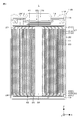
- FIG. 1 is a schematic cross-sectional view of a battery according to an embodiment.
- FIG. 2 is a diagram illustrating an example of the arrangement relationship between the positive electrode, the negative electrode, and the separator in the electrode winding body.
- FIG. 3A is a plan view of the positive electrode current collector plate
- FIG. 3B is a plan view of the negative electrode current collector plate.
- 4A to 4F are diagrams illustrating a battery assembly process according to the embodiment.
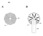
- 5A and 5B are a plan view of the end portion of the first embodiment and a plan view showing the position of the welding point group.
- 6A and 6B are a plan view of the end portion of the comparative example and a plan view showing the position of the welding point group.
- FIG. 7A and 7B are a plan view of the end portion of the second embodiment and a plan view showing the position of the welding point group.
- FIG. 8 is a plan view of the end portion of the third embodiment and a plan view showing the position of the welding point group.
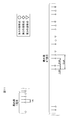
- FIG. 9 is a schematic diagram used for explaining the welding pitch of the second embodiment.
- FIG. 10 is a schematic diagram used for explaining the welding pitch of the third embodiment.
- FIG. 11 is a partially enlarged view of FIG.
- FIG. 12 is a schematic diagram used for explaining the welding pitch of the comparative example.
- FIG. 13 is a connection diagram used for explaining a battery pack as an application example of the present invention.
- FIG. 14 is a connection diagram used for explaining a power tool as an application example of the present invention.
- FIG. 15 is a connection diagram used for explaining an unmanned aerial vehicle as an application example of the present invention.
- FIG. 16 is a connection diagram used for explaining an electric vehicle as an application example of the present invention.
- a cylindrical lithium ion battery will be described as an example of the secondary battery.
- a battery other than the lithium ion battery or a battery other than the cylindrical shape may be used.
- FIG. 1 is a schematic cross-sectional view of the lithium ion battery 1.
- the lithium ion battery 1 is, for example, a cylindrical lithium ion battery 1 in which an electrode winding body 20 is housed inside an outer can 11.
- the lithium ion battery 1 includes, for example, a pair of insulating plates 12 and 13 and an electrode winding body 20 inside a cylindrical outer can 11.
- the lithium ion battery 1 may further include, for example, any one or more of the thermal resistance (PTC) element and the reinforcing member inside the outer can 11.
- PTC thermal resistance
- the outer can 11 is mainly a member for accommodating the electrode winding body 20.
- the outer can 11 is, for example, a cylindrical container in which one end is open and the other end is closed. That is, the outer can 11 has an open end portion (open end portion 11N).
- the outer can 11 contains any one or more of metal materials such as iron, aluminum and alloys thereof. However, the surface of the outer can 11 may be plated with any one or more of metal materials such as nickel.
- Each of the insulating plates 12 and 13 is, for example, a dish-shaped plate having a surface perpendicular to the winding axis of the electrode winding body 20, that is, a surface perpendicular to the Z axis in FIG. Further, the insulating plates 12 and 13 are arranged so as to sandwich the electrode winding body 20 with each other, for example.
- the battery lid 14 and the safety valve mechanism 30 are crimped to the open end portion 11N of the outer can 11 via the gasket 15.
- the battery lid 14 is the "lid member” of the embodiment of the present invention
- the gasket 15 is the “sealing member” of the embodiment of the present invention.
- the outer can 11 is sealed in a state where the electrode winding body 20 and the like are housed inside the outer can 11. Therefore, a structure (caulking structure 11R) in which the battery lid 14 and the safety valve mechanism 30 are crimped via the gasket 15 is formed at the open end portion 11N of the outer can 11. That is, the bent portion 11P is a so-called crimp portion, and the caulking structure 11R is a so-called crimp structure.
- the battery lid 14 is a member that mainly closes the open end 11N of the outer can 11 when the electrode winding body 20 or the like is housed inside the outer can 11.
- the battery lid 14 contains, for example, the same material as the material for forming the outer can 11.
- the central region of the battery lid 14 projects, for example, in the + Z direction. As a result, the region (peripheral region) of the battery lid 14 other than the central region is in contact with, for example, the safety valve mechanism 30.
- the gasket 15 is a member that is mainly interposed between the outer can 11 (bent portion 11P) and the battery lid 14 to seal the gap between the bent portion 11P and the battery lid 14.
- the surface of the gasket 15 may be coated with, for example, asphalt.
- the gasket 15 contains, for example, any one or more of the insulating materials.
- the type of the insulating material is not particularly limited, but is, for example, a polymer material such as polybutylene terephthalate (PBT) and polyp-mouth pyrene (PP). Above all, the insulating material is preferably polybutylene terephthalate. This is because the gap between the bent portion 11P and the battery lid 14 is sufficiently sealed while the outer can 11 and the battery lid 14 are electrically separated from each other.
- the safety valve mechanism 30 mainly releases the internal pressure of the outer can 11 by releasing the sealed state of the outer can 11 as necessary when the internal pressure (internal pressure) of the outer can 11 rises.
- the cause of the increase in the internal pressure of the outer can 11 is, for example, a gas generated due to a decomposition reaction of the electrolytic solution during charging / discharging.
- a band-shaped positive electrode 21 and a band-shaped negative electrode 22 are spirally wound with a separator 23 sandwiched between them, and are housed in an outer can 11 in a state of being impregnated with an electrolytic solution.
- the positive electrode 21 has a positive electrode active material layer 21B formed on one side or both sides of the positive electrode foil 21A, and the material of the positive electrode foil 21A is, for example, a metal foil made of aluminum or an aluminum alloy.
- the negative electrode 22 has a negative electrode active material layer 22B formed on one side or both sides of the negative electrode foil 22A, and the material of the negative electrode foil 22A is, for example, a metal foil made of nickel, a nickel alloy, copper, or a copper alloy.
- the separator 23 is a porous and insulating film that electrically insulates the positive electrode 21 and the negative electrode 22 while allowing the movement of substances such as ions and electrolytes.
- the positive electrode active material layer 21B and the negative electrode active material layer 22B each cover many parts of the positive electrode foil 21A and the negative electrode foil 22A, respectively, but both intentionally cover the periphery of one end in the minor axis direction of the band. Absent.
- the portion where the active material layers 21B and 22B are not coated is hereinafter appropriately referred to as an active material uncoated portion.
- the electrode winding body 20 is wound by stacking the positive electrode uncoated portion 21C and the negative electrode active material uncoated portion 22C via a separator 23 so as to face in opposite directions. ..
- FIG. 2 shows an example of the structure before winding in which the positive electrode 21, the negative electrode 22, and the separator 23 are laminated.
- the width of the active material uncoated portion 21C (upper shaded portion in FIG. 2) of the positive electrode is A
- the length of the portion where the active material uncoated portion 21C of the positive electrode protrudes from one end in the width direction of the separator 23 is C
- the length is D.
- the positive electrode active material uncoated portion 21C is made of, for example, aluminum and the negative electrode active material uncoated portion 22C is made of, for example, copper
- the positive electrode active material uncoated portion 21C is generally more negative electrode active material non-coated portion 21C. Softer than the covering portion 22C (low Young rate). Therefore, in one embodiment, A> B and C> D are more preferable.
- the positive electrode active material uncoated portion 21C and the negative electrode active material uncoated portion 22C are bent at the same pressure from both electrode sides at the same time. At that time, the height measured from the tip of the separator 23 of the bent portion may be about the same for the positive electrode 21 and the negative electrode 22.
- the active material uncoated portions 21C and 22C are bent and appropriately overlap each other, the active material uncoated portions 21C and 22C and the current collector plates 24 and 25 can be easily joined by laser welding.
- Joining in one embodiment means that they are joined by laser welding, but the joining method is not limited to laser welding.
- the insulating layer 101 (FIG. 2). The gray part) is covered.
- the lithium ion battery 1 is designed so that the width of the positive electrode active material layer 21B is shorter than the width of the negative electrode active material layer 22B. Therefore, when the insulating layer 101 is not provided, Li metal or the like may be deposited on the portion of the positive electrode non-coated portion 21C facing the negative electrode active material layer 22B during charging / discharging, or the battery 1 is impacted. At that time, the impact is not absorbed at all, and the active material uncoated portion 21C of the positive electrode may bend and come into contact with the negative electrode 22 to cause a short circuit.
- the insulating layer 101 is arranged to avoid these problems.
- the through hole 26 is a hole for inserting the winding core for assembling the electrode winding body 20 and the electrode rod for welding. Since the electrode winding body 20 is wound so that the active material uncoated portion 21C of the positive electrode and the active material uncoated portion 22C of the negative electrode face in opposite directions, one of the ends of the electrode winding body 20 ( The positive electrode active material uncoated portion 21C gathers at the end portion 41), and the negative electrode active material uncoated portion 22C gathers at the other end (end portion 42) of the electrode winding body 20.
- the active material uncoated portions 21C and 22C are bent so that the end portions 41 and 42 are flat surfaces.
- the bending direction is from the outer edges 27 and 28 of the ends 41 and 42 toward the through hole 26, and the active material uncoated portions on the adjacent circumferences are overlapped and bent in a wound state.
- the "flat surface” includes not only a completely flat surface but also a surface having some unevenness and surface roughness to the extent that the active material uncoated portion and the current collector plate can be joined. ..
- the central axis of the electrode winding body 20 has a through hole 26, and the grooves include a groove 43 that passes through the central axis and a groove 44 that does not pass through the central axis.
- the groove 43 passing through the central axis is a groove extending from the outer edges 27 and 28 of the ends 41 and 42 to the through hole 26 having the central axis, and the groove 44 not passing through the central axis is on the outer peripheral portion and reaches the through hole 26. Is a non-extending groove.
- the groove 43 remains in the flat surface even after the active material uncoated portions 21C and 22C are bent, and the portion without the groove 43 is joined (welded or the like) to the positive electrode current collector plate 24 or the negative electrode current collector plate 25. ing. In addition to the flat surface, the groove 43 may be joined to a part of the current collector plates 24 and 25.
- the detailed configuration of the electrode winding body 20, that is, the detailed configurations of the positive electrode 21, the negative electrode 22, the separator 23, and the electrolytic solution will be described later.
- the positive electrode current collector plate 24 and the negative electrode current collector plate 25 are arranged at the ends 41 and 42, and the active material of the positive electrode and the negative electrode existing at the ends 41 and 42 is not coated.
- the internal resistance of the battery is kept low by welding the portions 21C and 22C at multiple points. The fact that the ends 41 and 42 are bent to form a flat surface also contributes to lowering the resistance.
- FIGS. 3A and 3B show an example of a current collector plate.
- FIG. 3A is a positive electrode current collector plate 24, and FIG. 3B is a negative electrode current collector plate 25.
- the material of the positive current collector plate 24 is, for example, a metal plate made of aluminum or an aluminum alloy alone or a composite material
- the material of the negative electrode current collector plate 25 is, for example, a nickel, a nickel alloy, a copper or a copper alloy single unit or a composite material. It is a metal plate made of wood.
- the shape of the positive electrode current collector plate 24 is a flat fan-shaped fan-shaped portion 31 with a rectangular strip-shaped portion 32 attached. There is a hole 35 near the center of the fan-shaped portion 31, and the position of the hole 35 is a position corresponding to the through hole 26.
- the portion shown by the diagonal line in FIG. 3A is the insulating portion 32A to which the insulating tape is attached or the insulating material is applied to the strip-shaped portion 32, and the portion below the shaded portion in the drawing is to the sealing plate which also serves as an external terminal.
- the connection portion 32B In the case of a battery structure in which the through hole 26 does not have a metal center pin (not shown), the band-shaped portion 32 is unlikely to come into contact with the negative electrode potential portion, so that even if the insulating portion 32A is not provided. good. In that case, the width between the positive electrode 21 and the negative electrode 22 can be increased by an amount corresponding to the thickness of the insulating portion 32A to increase the charge / discharge capacity.
- the shape of the negative electrode current collector plate 25 is almost the same as that of the positive electrode current collector plate 24, but the strip-shaped portion is different.
- the strip-shaped portion 34 of the negative electrode foil in FIG. 3B is shorter than the strip-shaped portion 32 of the positive electrode foil, and has no portion corresponding to the insulating portion 32A.
- the band-shaped portion 34 has a round projection portion (projection) 37 indicated by a plurality of circles. During resistance welding, the current concentrates on the protrusions, the protrusions melt, and the strip-shaped portion 34 is welded to the bottom of the outer can 11.
- the negative electrode current collector plate 25 has a hole 36 near the center of the fan-shaped portion 33, and the position of the hole 36 is a position corresponding to the through hole 26. Since the fan-shaped portion 31 of the positive electrode current collector plate 24 and the fan-shaped portion 33 of the negative electrode current collector plate 25 have a fan shape, they cover a part of the ends 41 and 42. The reason for not covering the whole is to allow the electrolytic solution to smoothly permeate the electrode winding body 20 when assembling the battery 1, or to remove the gas generated when the battery becomes abnormally high temperature or overcharged. This is to make it easier to release to.
- the positive electrode active material layer 21B contains, as the positive electrode active material, any one or more of the positive electrode materials capable of occluding and releasing lithium. However, the positive electrode active material layer 21B may further contain any one or more of other materials such as a positive electrode binder and a positive electrode conductive agent.
- the positive electrode material is preferably a lithium-containing compound, and more specifically, a lithium-containing composite oxide, a lithium-containing phosphoric acid compound, or the like.
- the lithium-containing composite oxide is an oxide containing lithium and one or more other elements (elements other than lithium) as constituent elements, and is, for example, any one of a layered rock salt type and a spinel type. It has a crystal structure.
- the lithium-containing phosphoric acid compound is a phosphoric acid compound containing lithium and one or more other elements as constituent elements, and has a crystal structure such as an olivine type.
- the positive electrode binder contains, for example, any one or more of synthetic rubber and polymer compounds.
- the synthetic rubber is, for example, styrene-butadiene rubber, fluorine-based rubber, ethylene propylene diene and the like.
- the polymer compounds are, for example, polyvinylidene fluoride and polyimide.
- the positive electrode conductive agent contains, for example, any one or more of carbon materials and the like.
- the carbon material is, for example, graphite, carbon black, acetylene black, ketjen black and the like.
- the positive electrode conductive agent may be a metal material, a conductive polymer, or the like as long as it is a conductive material.
- the surface of the negative electrode foil 22A is preferably roughened. This is because the so-called anchor effect improves the adhesion of the negative electrode active material layer 22B to the negative electrode foil 22A.
- the surface of the negative electrode foil 22A may be roughened at least in the region facing the negative electrode active material layer 22B.
- the roughening method is, for example, a method of forming fine particles by using an electrolytic treatment. In the electrolytic treatment, fine particles are formed on the surface of the negative electrode foil 22A by an electrolytic method in the electrolytic cell, so that the surface of the negative electrode foil 22A is provided with irregularities.
- the copper foil produced by the electrolytic method is generally called an electrolytic copper foil.
- the negative electrode active material layer 22B contains any one or more of the negative electrode materials capable of occluding and releasing lithium as the negative electrode active material. However, the negative electrode active material layer 22B may further contain any one or more of other materials such as a negative electrode binder and a negative electrode conductive agent.
- the negative electrode material is, for example, a carbon material. This is because a high energy density can be stably obtained because the change in the crystal structure during the occlusion and release of lithium is very small. Further, since the carbon material also functions as a negative electrode conductive agent, the conductivity of the negative electrode active material layer 22B is improved.
- the carbon material is, for example, graphitizable carbon, non-graphitizable carbon, graphite and the like.
- the interplanar spacing of the (002) plane in graphitizable carbon is preferably 0.37 nm or more, and the interplanar spacing of the (002) plane in graphite is preferably 0.34 nm or less.
- the carbon material is, for example, pyrolytic carbons, cokes, glassy carbon fibers, calcined organic polymer compound, activated carbon, carbon blacks and the like. These cokes include pitch coke, needle coke, petroleum coke and the like.
- the organic polymer compound calcined product is obtained by calcining (carbonizing) a polymer compound such as a phenol resin and a furan resin at an appropriate temperature.
- the carbon material may be low crystalline carbon heat-treated at a temperature of about 1000 ° C. or lower, or amorphous carbon.
- the shape of the carbon material may be any of fibrous, spherical, granular and scaly.
- the open circuit voltage that is, the battery voltage
- the same positive electrode activity is compared with the case where the open circuit voltage at the time of full charge is 4.20 V. Even if a substance is used, the amount of lithium released per unit mass increases, so the amounts of the positive electrode active material and the negative electrode active material are adjusted accordingly. As a result, a high energy density can be obtained.
- the separator 23 is interposed between the positive electrode 21 and the negative electrode 22, and allows lithium ions to pass through while preventing a short circuit of current due to contact between the positive electrode 21 and the negative electrode 22.
- the separator 23 is, for example, any one type or two or more types of porous membranes such as synthetic resin and ceramic, and may be a laminated film of two or more types of porous membranes.
- Synthetic resins include, for example, polytetrafluoroethylene, polypropylene and polyethylene.
- the separator 23 may include, for example, the above-mentioned porous film (base material layer) and a polymer compound layer provided on one side or both sides of the base material layer. This is because the adhesion of the separator 23 to each of the positive electrode 21 and the negative electrode 22 is improved, so that the distortion of the electrode winding body 20 is suppressed. As a result, the decomposition reaction of the electrolytic solution is suppressed, and the leakage of the electrolytic solution impregnated in the base material layer is also suppressed. Therefore, the resistance is less likely to increase even if charging and discharging are repeated, and battery swelling is suppressed. Will be done.
- the polymer compound layer contains a polymer compound such as polyvinylidene fluoride. This is because it has excellent physical strength and is electrochemically stable. However, the polymer compound may be other than polyvinylidene fluoride.
- a solution in which the polymer compound is dissolved in an organic solvent or the like is applied to the base material layer, and then the base material layer is dried. After immersing the base material layer in the solution, the base material layer may be dried.
- the polymer compound layer may contain any one or more of insulating particles such as inorganic particles.
- the types of inorganic particles are, for example, aluminum oxide and aluminum nitride.
- the electrolyte contains a solvent and an electrolyte salt. However, the electrolytic solution may further contain any one or more of other materials such as additives.
- the solvent contains any one or more of non-aqueous solvents such as organic solvents.
- the electrolytic solution containing a non-aqueous solvent is a so-called non-aqueous electrolytic solution.
- Non-aqueous solvents are, for example, cyclic carbonates, chain carbonates, lactones, chain carboxylic acid esters and nitriles (mononitriles).
- the electrolyte salt contains, for example, any one or more of salts such as lithium salt.
- the electrolyte salt may contain, for example, a salt other than the lithium salt.
- the salt other than lithium is, for example, a salt of a light metal other than lithium.
- Lithium salts include, for example, lithium hexafluorophosphate (LiPF 6 ), lithium tetrafluoroborate (LiBF 4 ), lithium perchlorate (LiClO 4 ), lithium hexafluorophosphate (LiAsF 6 ), and tetraphenyl.
- Lithium borate LiB (C 6 H 5 ) 4
- lithium methanesulfonate LiCH 3 SO 3
- lithium trifluoromethanesulfonate LiCF 3 SO 3
- lithium tetrachloroaluminate LiAlCl 4
- LiCl lithium chloride
- LiBr lithium bromide
- any one or more of lithium hexafluorophosphate, lithium tetrafluoroborate, lithium perchlorate and lithium hexafluoride is preferable, and lithium hexafluorophosphate is more preferable. ..
- the content of the electrolyte salt is not particularly limited, but is preferably 0.3 mol / kg to 3 mol / kg with respect to the solvent.
- the positive electrode active material was applied to the surface of the strip-shaped positive electrode foil 21A to form the positive electrode
- the negative electrode active material was applied to the surface of the band-shaped negative electrode foil 22A to form the negative electrode 22.
- the active material uncoated portions 21C and 22C in which the positive electrode active material and the negative electrode active material are not coated are prepared at one end of the positive electrode 21 and the negative electrode 22 in the lateral direction, and the active material uncoated portions 21C, A notch was made in a part of 22C, which corresponds to the beginning of winding when winding.
- the positive electrode 21 and the negative electrode 22 were subjected to steps such as drying. Then, the active material uncoated portion 21C of the positive electrode and the active material uncoated portion 22C of the negative electrode are overlapped with each other via the separator 23 so as to be in opposite directions, so that a through hole 26 is formed on the central axis, and a notch is prepared.
- the electrode winding body 20 as shown in FIG. 4A was produced by winding in a spiral shape so that is arranged near the central axis.
- FIG. 4B by pressing the end of a thin flat plate (for example, 0.5 mm in thickness) perpendicular to the ends 41 and 42, the ends 41 and 42 are locally bent and the groove 43 is formed.
- a groove 43 extending from the through hole 26 in the radial direction toward the central axis was produced.
- the number and arrangement of the grooves 43 shown in FIG. 4B are merely examples.
- FIG. 4C the same pressure is simultaneously applied from both poles in a direction substantially perpendicular to the ends 41 and 42, and the positive electrode active material uncoated portion 21C and the negative electrode active material uncoated portion 22C are bent.
- the ends 41 and 42 were formed so as to be a flat surface.
- the strips 32 and 34 of the current collector plates 24 and 25 are bent, and the insulating plates 12 and 13 (or insulating tape) are attached to the positive electrode current collector plate 24 and the negative electrode current collector plate 25.
- the electrode winding body 20 assembled as described above was inserted into the outer can 11 shown in 4E, and the bottom of the outer can 11 was welded. After the electrolytic solution was injected into the outer can 11, it was sealed with the gasket 15 and the battery lid 14 as shown in FIG. 4F.
- the uncoated portion of the active material is bent to flatten the exposed core body (foil).
- Welding of the exposed core body (foil) and the current collector plate, which are flat surfaces, is performed by laser welding. It is necessary to reduce the cell resistance in order to discharge efficiently. In order to reduce the resistance, it is necessary to improve the adhesion between the current collector plate and the exposed core body (foil) and stabilize the welding. In order to improve the adhesion, it is necessary to have a pressing condition that eliminates deformation and gaps of the object to be welded while pressing on a flatter surface with firm pressure.
- the first embodiment of the present invention by performing welding in the region where the groove 43 does not exist, it is possible to perform welding in a state where gaps are less likely to occur and the pressing stress is more stable. Therefore, the resistance can be lowered. In addition, since heat is generated extremely in places where there are gaps during welding, melt-off (perforations), spatter, etc. are likely to occur, and there is a risk of metal contamination. Therefore, welding to places where there is no groove 43 is possible. It is possible to supply batteries with high quality and reliability. Further, in the second embodiment of the present invention, a more efficient high is achieved by securing an area where the second and third welding point groups (welding points) can be provided for the purpose of collecting efficiency on the outer peripheral side. It has become possible to make batteries with output (high rate characteristics).
- Example 1 As shown in FIG. 5A, at the end 41, eight grooves 43 passing through the central axis are formed at equiangular intervals.
- the case where the fan-shaped portion 31 of the positive electrode current collector plate 24 is laser-welded to the end portion 41 will be described, but the same applies to the case where the fan-shaped portion 33 of the negative electrode current collector plate 25 is laser-welded to the end portion 42. ..
- the strips of the positive electrode current collector plate 24 and the negative electrode current collector plate 25 are bent portions and are not welded.
- the material of the positive electrode current collector plate 24 was Al alloy, and the material of the negative electrode current collector plate 25 was Cu alloy.
- the size of the battery was 21700 (diameter 21 (mm), length 70 (mm)).
- the portion of the end portion 41 having no groove 43 and the positive electrode current collector plate 24 were laser welded.
- FIG. 5B shows the result of laser welding, and the welding point group is formed radially.
- black circles ( ⁇ ) represent good welding points (welding points). In the case of Example 1, an unstable welding portion did not occur.
- Example 1 by laser welding at a position avoiding the groove 43, the adhesion of the welded surface is enhanced, it is easy to secure a welding state in which gaps are unlikely to occur, and stable welding becomes possible. Therefore, a high output (high rate characteristic) battery with low internal resistance can be realized.
- Example 2 is shown in FIGS. 7A and 7B.
- the fan-shaped portion 31 of the positive electrode current collector plate 24 was laser-welded to the end portion 41 shown in FIG. 7A (similar to FIGS. 5A and 6A).
- the portion of the end portion 41 having no groove 43 and the positive electrode current collector plate 24 were laser welded to form a first group of welding points indicated by white circles.
- the first group of welding points is arranged radially from the vicinity of the central hole to the vicinity of the outermost circumference at a position approximately intermediate between the adjacent grooves 43.
- a second welding point group (welding points are indicated by diamond marks ( ⁇ )) was formed in a region that does not overlap with both the arrangement of the first welding point group and the groove 43.
- the second welding point group was formed in the radial direction of the end portion 41 in a region excluding the vicinity of the innermost circumference, for example, a region on the outer peripheral side from the vicinity of the intermediate position. Further, the second welding point group was formed in the radial direction adjacent to one side (the region on the left side when viewed from the drawing) of the arrangement of the first welding point group.
- FIG. 8 shows Example 3.
- a third welding point group (welding points are indicated by triangular marks ( ⁇ )) is added to the second embodiment.
- the third welding point group is a region that does not overlap both the arrangement of the first and second welding point groups and the groove 43, and is a region excluding the region near the innermost circumference in the radial direction of the end portion 41, for example. It is formed on the outer peripheral side from the vicinity of the intermediate position in the radial direction of the end portion 41. Further, the third welding point group was formed in the radial direction adjacent to one side (the region on the right side in the drawing) of the first welding point group in which the second welding point group was not formed. Therefore, a second welding point group and a third welding point group exist adjacent to both sides of the first welding point group on the outer peripheral side from the vicinity of the intermediate position in the radial direction of the end portion 41.
- the adhesion of the welded surface is enhanced and it is easy to secure a welded state in which a gap is unlikely to occur, and the welding position is stable. Welding is possible. Furthermore, the interval between welding points (called welding pitch) can be reduced, and the difference in peripheral length of welding pitch is eliminated to improve current collection efficiency, realizing a high output (high rate characteristic) battery with lower internal resistance. can do.
- FIG. 9 is a developed view of the first and second welding point groups.
- a range of 360 ° clockwise starting from the point S is defined as one circumference of the electrode winding body 20.
- Only the first welding point group exists in the vicinity of the innermost circumference such as the innermost circumference (first lap) and the innermost circumference (second lap).
- the intermediate laps for example, the 23rd lap and the 24th lap
- the first welding point group and the second welding point group exist up to the outermost circumference (for example, the 47th lap).
- the welding pitch can be made smaller as compared with the case of only the first welding point group, and the welding pitch differs between the inner peripheral side and the outer peripheral side. It is possible to suppress this (difference in circumference).
- FIGS. 10 and 11 are development views of the first, second and third welding point groups. Only the first welding point group exists in the vicinity of the innermost circumference such as the innermost circumference (first lap) and the innermost circumference (second lap). Then, in the intermediate laps (for example, the 23rd lap and the 24th lap), there are a first welding point group, a second welding point group, and a third welding point group. After that, the first welding point group, the second welding point group, and the third welding point group exist up to the outermost circumference (for example, the 47th lap).
- the difference in the peripheral length of the welding pitch can be suppressed by the second and third welding point groups. Since the third welding point group is added to the third embodiment, the difference in peripheral length can be further suppressed as compared with the second embodiment. As shown in FIG. 11, in the third embodiment, when the welding pitch on the innermost circumference (first lap) is 1A, the welding pitch on the outermost circumference (for example, the 47th lap) is 1.3A to 2.8A.
- the welding pitch becomes large. That is, at the outermost circumference (for example, the 47th lap), it is about 5.5A. As described above, in the second and third embodiments, the welding pitch can be reduced and the difference in peripheral length can be suppressed. When the welding pitch is large, the electron transfer distance from the active material to the current collector plate increases, and the current collection efficiency on the winding end side (outer peripheral side) decreases.
- the welding pitch is reduced, the peripheral length difference is reduced as much as possible, and the current collection efficiency is improved. It is possible to realize a high output (high rate characteristic) battery with lower internal resistance.
- Table 1 shows the results of battery evaluation.
- Example 1 in which the welding point group is only the first welding point group, Example 2 in which the first and second welding point groups are formed, and Example 3 in which the first, second and third welding point groups are formed.
- the resistance ACR (m ⁇ ), DC resistance DCR (m ⁇ ), and load discharge rate at AC 1 kHz were measured for each of the above.
- the DC resistance is obtained by calculating the slope of the voltage when the discharge current is increased from 0 (A) to 100 (A) in 5 seconds.
- the load discharge rate after charging 3.5 (h) with a constant current 2 (A), the battery is discharged at a current value of 40 (A), a cutoff voltage of 2.0 (V), and an ambient temperature of 23 ° C. It is obtained by dividing the discharge capacity (mAh) until the surface temperature of the battery reaches 75 ° C. by the charge capacity (mAh).
- the DC resistance it is 10.5 (m ⁇ ) in the case of only the first welding point group, and 9.5 (m ⁇ ) in the case of Example 2 in which the first and second welding point groups are formed.
- the value is 9 (m ⁇ ).
- the 40A load discharge rate is 80 (%) in the case of only the first welding point group, and 95 (%) in the case of Example 2 in which the first and second welding point groups are formed.
- the value is 100 (%). From the results in Table 1, it can be seen that the present invention can improve the current collecting efficiency and realize a high output (high rate characteristic) battery with lower internal resistance.
- FIG. 13 is a block diagram showing a circuit configuration example when the battery according to the embodiment of the present invention (hereinafter, appropriately referred to as a secondary battery) is applied to the battery pack 330.
- the battery pack 300 includes a switch unit 304 including an assembled battery 301, an exterior, a charge control switch 302a, and a discharge control switch 303a, a current detection resistor 307, a temperature detection element 308, and a control unit 310.
- the battery pack 300 includes a positive electrode terminal 321 and a negative electrode terminal 322, and at the time of charging, the positive electrode terminal 321 and the negative electrode terminal 322 are connected to the positive electrode terminal and the negative electrode terminal of the charger, respectively, and charging is performed. Further, when using an electronic device, the positive electrode terminal 321 and the negative electrode terminal 322 are connected to the positive electrode terminal and the negative electrode terminal of the electronic device, respectively, and discharge is performed.
- the assembled battery 301 is formed by connecting a plurality of secondary batteries 301a in series and / or in parallel.
- the secondary battery 301a is the secondary battery of the present invention.
- FIG. 13 the case where the six secondary batteries 301a are connected in two parallels and three series (2P3S) is shown as an example, but in addition, n parallel m series (n and m are integers). In addition, any connection method may be used.
- the switch unit 304 includes a charge control switch 302a and a diode 302b, and a discharge control switch 303a and a diode 303b, and is controlled by the control unit 310.
- the diode 302b has a polarity opposite to the charging current flowing from the positive electrode terminal 321 toward the assembled battery 301 and a forward polarity with respect to the discharging current flowing from the negative electrode terminal 322 toward the assembled battery 301.
- the diode 303b has polarities in the forward direction with respect to the charge current and in the reverse direction with respect to the discharge current.
- the switch portion 304 is provided on the + side, but it may be provided on the ⁇ side.
- the charge control switch 302a is turned off when the battery voltage reaches the overcharge detection voltage, and is controlled by the charge / discharge control unit so that the charge current does not flow in the current path of the assembled battery 301. After the charge control switch 302a is turned off, only discharging is possible via the diode 302b. Further, it is controlled by the control unit 310 so as to be turned off when a large current flows during charging and cut off the charging current flowing in the current path of the assembled battery 301.
- the discharge control switch 303a is turned off when the battery voltage becomes the over-discharge detection voltage, and is controlled by the control unit 310 so that the discharge current does not flow in the current path of the assembled battery 301. After the discharge control switch 303a is turned off, only charging is possible via the diode 303b. Further, it is controlled by the control unit 310 so as to be turned off when a large current flows during discharging and to cut off the discharging current flowing in the current path of the assembled battery 301.
- the temperature detection element 308 is, for example, a thermistor, which is provided in the vicinity of the assembled battery 301, measures the temperature of the assembled battery 301, and supplies the measured temperature to the control unit 310.
- the voltage detection unit 311 measures the voltage of the assembled battery 301 and each of the secondary batteries 301a constituting the assembled battery 301, A / D converts the measured voltage, and supplies the measured voltage to the control unit 310.
- the current measuring unit 313 measures the current using the current detection resistor 307, and supplies the measured current to the control unit 310.
- the switch control unit 314 controls the charge control switch 302a and the discharge control switch 303a of the switch unit 304 based on the voltage and current input from the voltage detection unit 311 and the current measurement unit 313.
- the switch control unit 314 sends a control signal to the switch unit 304 when any voltage of the secondary battery 301a becomes equal to or lower than the overcharge detection voltage or the overdischarge detection voltage, or when a large current suddenly flows. By sending, overcharge, overdischarge, and overcurrent charge / discharge are prevented.
- the overcharge detection voltage is defined as, for example, 4.20V ⁇ 0.05V
- the overdischarge detection voltage is defined as, for example, 2.4V ⁇ 0.1V. ..
- the charge / discharge switch a semiconductor switch such as a MOSFET can be used.
- the parasitic diode of the MOSFET functions as the diodes 302b and 303b.
- the switch control unit 314 supplies control signals DO and CO to the respective gates of the charge control switch 302a and the discharge control switch 303a, respectively.
- the charge control switch 302a and the discharge control switch 303a are of the P channel type, they are turned on by a gate potential lower than a predetermined value by a predetermined value or more. That is, in the normal charging / discharging operation, the control signals CO and DO are set to the low level, and the charging control switch 302a and the discharging control switch 303a are turned on.
- control signals CO and DO are set to a high level, and the charge control switch 302a and the discharge control switch 303a are turned off.
- the memory 317 is composed of a RAM or a ROM, for example, an EPROM (Erasable Programmable Read Only Memory) which is a non-volatile memory.
- EPROM Erasable Programmable Read Only Memory
- the numerical value calculated by the control unit 310, the internal resistance value of the battery in the initial state of each secondary battery 301a measured at the stage of the manufacturing process, and the like are stored in advance, and can be rewritten as appropriate. .. Further, by storing the fully charged capacity of the secondary battery 301a, for example, the remaining capacity can be calculated together with the control unit 310.
- the temperature detection unit 318 measures the temperature using the temperature detection element 308, performs charge / discharge control when abnormal heat generation occurs, and corrects the calculation of the remaining capacity.
- Examples of power storage systems etc.
- the battery according to the embodiment of the present invention described above can be mounted on or used to supply electric power to a device such as an electronic device, an electric vehicle, an electric aircraft, or a power storage device.
- Electronic devices include, for example, notebook computers, smartphones, tablet terminals, PDAs (Personal Digital Assistants), mobile phones, wearable terminals, cordless phone handsets, video movies, digital still cameras, electronic books, electronic dictionaries, music players, radios, etc. Headphones, game machines, navigation systems, memory cards, pacemakers, hearing aids, power tools, electric shavers, refrigerators, air conditioners, TVs, stereos, water heaters, microwave ovens, dishwashers, washing machines, dryers, lighting equipment, toys, medical care Equipment, robots, road conditioners, traffic lights, etc. can be mentioned.
- Examples of electric vehicles include railroad vehicles, golf carts, electric carts, electric vehicles (including hybrid vehicles), etc., which are used as drive power sources or auxiliary power sources.
- Examples of the power storage device include a power storage power source for buildings such as houses or power generation equipment.
- the electric screwdriver 431 contains a motor 433 such as a DC motor in the main body. The rotation of the motor 433 is transmitted to the shaft 434, and the shaft 434 drives a screw into the object.
- the electric screwdriver 431 is provided with a trigger switch 432 operated by the user.
- the battery pack 430 and the motor control unit 435 are housed in the lower housing of the handle of the electric screwdriver 431.
- the battery pack 300 can be used as the battery pack 430.
- the motor control unit 435 controls the motor 433.
- Each part of the electric screwdriver 431 other than the motor 433 may be controlled by the motor control unit 435.
- the battery pack 430 and the electric screwdriver 431 are engaged with each other by engaging members provided therein.
- each of the battery pack 430 and the motor control unit 435 is provided with a microcomputer. Battery power is supplied from the battery pack 430 to the motor control unit 435, and information on the battery pack 430 is communicated between both microcomputers.
- the battery pack 430 is detachable from, for example, the electric screwdriver 431.
- the battery pack 430 may be built in the electric screwdriver 431.
- the battery pack 430 is attached to the charging device at the time of charging.
- a part of the battery pack 430 may be exposed to the outside of the electric screwdriver 431 so that the exposed portion can be visually recognized by the user.
- an LED may be provided on the exposed portion of the battery pack 430 so that the user can confirm whether the LED emits light or turns off.
- the motor control unit 435 controls, for example, the rotation / stop of the motor 433 and the rotation direction. Further, the power supply to the load is cut off at the time of over-discharging.
- the trigger switch 432 is inserted between the motor 433 and the motor control unit 435, for example, and when the user pushes the trigger switch 432, power is supplied to the motor 433 and the motor 433 rotates. When the user returns the trigger switch 432, the rotation of the motor 433 is stopped.
- FIG. 15 is a plan view of an unmanned aerial vehicle.
- the airframe is composed of a cylindrical or square tubular body portion as a central portion and support shafts 442a to 442f fixed to the upper part of the body portion.
- the body portion has a hexagonal tubular shape, and six support shafts 442a to 442f extend radially from the center of the body portion at equiangular intervals.
- the body portion and the support shafts 442a to 442f are made of a lightweight and high-strength material.
- Motors 443a to 443f as drive sources for rotary blades are attached to the tips of the support shafts 442a to 442f, respectively.
- Rotor blades 444a to 444f are attached to the rotating shafts of the motors 443a to 443f.
- the circuit unit 445 including the motor control circuit for controlling each motor is attached to the central portion (upper part of the body portion) where the support shafts 442a to 442f intersect.
- the battery section as a power source is located at the lower position of the fuselage section.
- the battery section has three battery packs to supply power to a pair of motors and rotor blades having a 180 degree facing distance.
- Each battery pack has, for example, a lithium ion secondary battery and a battery control circuit that controls charging and discharging.
- the battery pack 300 can be used as the battery pack.
- the motor 443a and the rotary blade 444a and the motor 443d and the rotary blade 444d form a pair.
- FIG. 16 schematically shows an example of the configuration of a hybrid vehicle adopting the series hybrid system to which the present invention is applied.
- the series hybrid system is a vehicle that runs on a power driving force converter using the electric power generated by a generator powered by an engine or the electric power temporarily stored in a battery.
- the hybrid vehicle 600 includes an engine 601, a generator 602, a power driving force converter 603, a drive wheel 604a, a drive wheel 604b, a wheel 605a, a wheel 605b, a battery 608, a vehicle control device 609, various sensors 610, and a charging port 611. Is installed.
- the battery pack 300 of the present invention described above is applied to the battery 608.
- the hybrid vehicle 600 travels by using the electric power driving force conversion device 603 as a power source.
- An example of the power driving force conversion device 603 is a motor.
- the electric power of the battery 608 operates the electric power driving force conversion device 603, and the rotational force of the electric power driving force conversion device 603 is transmitted to the drive wheels 604a and 604b.
- DC-AC DC-AC
- AC-DC conversion AC-DC conversion
- the power driving force conversion device 603 can be applied to both an AC motor and a DC motor.
- the various sensors 610 control the engine speed via the vehicle control device 609, and control the opening degree (throttle opening degree) of a throttle valve (not shown).
- the various sensors 610 include a speed sensor, an acceleration sensor, an engine speed sensor, and the like.
- the rotational force of the engine 601 is transmitted to the generator 602, and the electric power generated by the generator 602 by the rotational force can be stored in the battery 608.
- the resistance force at the time of deceleration is applied to the power driving force conversion device 603 as a rotational force, and the regenerative power generated by the power driving force conversion device 603 by this rotational force is the battery 608. Accumulate in.
- the battery 608 By connecting the battery 608 to an external power source of the hybrid vehicle 600, it is possible to receive electric power from the external power source using the charging port 611 as an input port and store the received electric power.
- an information processing device that performs information processing related to vehicle control based on information related to the secondary battery may be provided.
- an information processing device for example, there is an information processing device that displays the remaining battery level based on information on the remaining battery level.
- the present invention is also effective for a parallel hybrid vehicle in which the outputs of the engine and the motor are used as drive sources, and the three methods of traveling only by the engine, traveling only by the motor, and traveling by the engine and the motor are appropriately switched and used. Applicable. Further, the present invention can be effectively applied to a so-called electric vehicle that travels by being driven only by a drive motor without using an engine.
- Negative electrode current collector plate 26 ... through hole, 27, 28 ... outer edge, 41, 42 ... end, 43 ... groove
Landscapes
- Chemical & Material Sciences (AREA)
- Engineering & Computer Science (AREA)
- Chemical Kinetics & Catalysis (AREA)
- Electrochemistry (AREA)
- General Chemical & Material Sciences (AREA)
- Manufacturing & Machinery (AREA)
- Materials Engineering (AREA)
- Power Engineering (AREA)
- Life Sciences & Earth Sciences (AREA)
- Sustainable Development (AREA)
- Sustainable Energy (AREA)
- Transportation (AREA)
- Mechanical Engineering (AREA)
- Aviation & Aerospace Engineering (AREA)
- Secondary Cells (AREA)
- Connection Of Batteries Or Terminals (AREA)
- Battery Electrode And Active Subsutance (AREA)
Priority Applications (4)
| Application Number | Priority Date | Filing Date | Title |
|---|---|---|---|
| CN202410368242.XA CN118156634A (zh) | 2019-07-30 | 2020-07-16 | 二次电池、电池组 |
| CN202080055593.5A CN114207870B (zh) | 2019-07-30 | 2020-07-16 | 二次电池、电池组、电子设备、电动工具、电动式航空器以及电动车辆 |
| JP2021536925A JP7298691B2 (ja) | 2019-07-30 | 2020-07-16 | 二次電池、電池パック、電子機器、電動工具、電動式航空機及び電動車両 |
| US17/565,066 US12308395B2 (en) | 2019-07-30 | 2021-12-29 | Secondary battery, battery pack, electronic device, electric tool, electric aircraft, and electric vehicle |
Applications Claiming Priority (2)
| Application Number | Priority Date | Filing Date | Title |
|---|---|---|---|
| JP2019139816 | 2019-07-30 | ||
| JP2019-139816 | 2019-07-30 |
Related Child Applications (1)
| Application Number | Title | Priority Date | Filing Date |
|---|---|---|---|
| US17/565,066 Continuation US12308395B2 (en) | 2019-07-30 | 2021-12-29 | Secondary battery, battery pack, electronic device, electric tool, electric aircraft, and electric vehicle |
Publications (1)
| Publication Number | Publication Date |
|---|---|
| WO2021020139A1 true WO2021020139A1 (ja) | 2021-02-04 |
Family
ID=74229620
Family Applications (1)
| Application Number | Title | Priority Date | Filing Date |
|---|---|---|---|
| PCT/JP2020/027613 Ceased WO2021020139A1 (ja) | 2019-07-30 | 2020-07-16 | 二次電池、電池パック、電子機器、電動工具、電動式航空機及び電動車両 |
Country Status (4)
| Country | Link |
|---|---|
| US (1) | US12308395B2 (https=) |
| JP (1) | JP7298691B2 (https=) |
| CN (2) | CN118156634A (https=) |
| WO (1) | WO2021020139A1 (https=) |
Cited By (7)
| Publication number | Priority date | Publication date | Assignee | Title |
|---|---|---|---|---|
| CN114975846A (zh) * | 2021-02-19 | 2022-08-30 | 株式会社Lg新能源 | 电极组件、电池以及包括其的电池组和车辆 |
| CN116190760A (zh) * | 2021-11-26 | 2023-05-30 | 泰星能源解决方案有限公司 | 电池 |
| JPWO2023162530A1 (https=) * | 2022-02-22 | 2023-08-31 | ||
| CN116724459A (zh) * | 2021-09-30 | 2023-09-08 | 宁德时代新能源科技股份有限公司 | 电池单体、电池、用电设备及电池单体的制造方法和设备 |
| WO2025142919A1 (ja) * | 2023-12-28 | 2025-07-03 | パナソニックIpマネジメント株式会社 | 蓄電装置 |
| US12537229B2 (en) | 2021-02-19 | 2026-01-27 | Lg Energy Solution, Ltd. | Riveting structure of electrode terminal, and cylindrical battery cell, battery pack and vehicle including the same |
| US12609362B2 (en) | 2021-01-19 | 2026-04-21 | Lg Energy Solution, Ltd. | Battery, and battery pack and vehicle comprising the same |
Families Citing this family (4)
| Publication number | Priority date | Publication date | Assignee | Title |
|---|---|---|---|---|
| CN113740751B (zh) * | 2020-05-27 | 2024-08-16 | 台达电子企业管理(上海)有限公司 | 电池内阻检测装置与方法 |
| CN220821862U (zh) * | 2023-09-15 | 2024-04-19 | 中创新航科技集团股份有限公司 | 一种电池以及电池包 |
| KR20250053625A (ko) * | 2023-10-13 | 2025-04-22 | 주식회사 엘지에너지솔루션 | 원통형 배터리 셀 및 이에 적용되는 집전체, 그리고 이를 포함하는 배터리 팩 및 자동차 |
| CN222927734U (zh) * | 2024-06-13 | 2025-05-30 | 惠州亿纬动力电池有限公司 | 极耳焊接结构及电池 |
Citations (4)
| Publication number | Priority date | Publication date | Assignee | Title |
|---|---|---|---|---|
| JP2003203620A (ja) * | 2002-01-08 | 2003-07-18 | Matsushita Electric Ind Co Ltd | リチウムイオン電池とその注液法 |
| JP2006040902A (ja) * | 2004-07-28 | 2006-02-09 | Samsung Sdi Co Ltd | 二次電池及びこの二次電池の製造方法 |
| JP2007265846A (ja) * | 2006-03-29 | 2007-10-11 | Sanyo Electric Co Ltd | 円筒形電池およびその製造方法 |
| WO2013001821A1 (ja) * | 2011-06-28 | 2013-01-03 | 日本ケミコン株式会社 | 蓄電デバイスおよび蓄電デバイスの製造方法 |
Family Cites Families (11)
| Publication number | Priority date | Publication date | Assignee | Title |
|---|---|---|---|---|
| JP3334683B2 (ja) * | 1999-06-28 | 2002-10-15 | エヌイーシートーキン株式会社 | 非水電解液二次電池およびその製造方法 |
| JP3912574B2 (ja) | 2000-12-04 | 2007-05-09 | 株式会社ユアサ開発 | 密閉形電池 |
| CN1309105C (zh) * | 2003-12-24 | 2007-04-04 | 松下电器产业株式会社 | 卷式电化学元件用极板组和电池 |
| JP2007335156A (ja) * | 2006-06-13 | 2007-12-27 | Honda Motor Co Ltd | 蓄電素子 |
| JP2008166030A (ja) | 2006-12-27 | 2008-07-17 | Sanyo Electric Co Ltd | 渦巻電極体の製造方法及びこれを用いた密閉型電池の製造方法 |
| WO2009096160A1 (ja) * | 2008-01-28 | 2009-08-06 | Panasonic Corporation | 二次電池用集電端子板、二次電池および二次電池の製造方法 |
| JP2011238375A (ja) * | 2010-05-06 | 2011-11-24 | Hitachi Vehicle Energy Ltd | 二次電池およびその製造方法 |
| JP6819107B2 (ja) * | 2016-07-12 | 2021-01-27 | 株式会社村田製作所 | 電池、電池パック、電子機器、電動車両、蓄電装置および電力システム |
| DE202018006912U1 (de) * | 2017-04-14 | 2024-05-16 | Lg Energy Solution, Ltd. | Sekundärbatterie und Herstellung |
| JP6763345B2 (ja) * | 2017-05-31 | 2020-09-30 | 株式会社村田製作所 | 二次電池、電池パック、電動車両、電力貯蔵システム、電動工具および電子機器 |
| EP4307461A4 (en) * | 2021-11-19 | 2025-10-29 | Lg Energy Solution Ltd | ELECTRODE ASSEMBLY, BATTERY, AND BATTERY BLOCK AND VEHICLE INCLUDING THEM |
-
2020
- 2020-07-16 WO PCT/JP2020/027613 patent/WO2021020139A1/ja not_active Ceased
- 2020-07-16 CN CN202410368242.XA patent/CN118156634A/zh active Pending
- 2020-07-16 CN CN202080055593.5A patent/CN114207870B/zh active Active
- 2020-07-16 JP JP2021536925A patent/JP7298691B2/ja active Active
-
2021
- 2021-12-29 US US17/565,066 patent/US12308395B2/en active Active
Patent Citations (4)
| Publication number | Priority date | Publication date | Assignee | Title |
|---|---|---|---|---|
| JP2003203620A (ja) * | 2002-01-08 | 2003-07-18 | Matsushita Electric Ind Co Ltd | リチウムイオン電池とその注液法 |
| JP2006040902A (ja) * | 2004-07-28 | 2006-02-09 | Samsung Sdi Co Ltd | 二次電池及びこの二次電池の製造方法 |
| JP2007265846A (ja) * | 2006-03-29 | 2007-10-11 | Sanyo Electric Co Ltd | 円筒形電池およびその製造方法 |
| WO2013001821A1 (ja) * | 2011-06-28 | 2013-01-03 | 日本ケミコン株式会社 | 蓄電デバイスおよび蓄電デバイスの製造方法 |
Cited By (12)
| Publication number | Priority date | Publication date | Assignee | Title |
|---|---|---|---|---|
| US12609362B2 (en) | 2021-01-19 | 2026-04-21 | Lg Energy Solution, Ltd. | Battery, and battery pack and vehicle comprising the same |
| CN114975846A (zh) * | 2021-02-19 | 2022-08-30 | 株式会社Lg新能源 | 电极组件、电池以及包括其的电池组和车辆 |
| JP2023553926A (ja) * | 2021-02-19 | 2023-12-26 | エルジー エナジー ソリューション リミテッド | 電極組立体、バッテリー、それを含むバッテリーパック及び自動車 |
| JP7675188B2 (ja) | 2021-02-19 | 2025-05-12 | エルジー エナジー ソリューション リミテッド | 電極組立体、バッテリー、それを含むバッテリーパック及び自動車 |
| EP4270628A4 (en) * | 2021-02-19 | 2025-06-25 | LG Energy Solution, Ltd. | ELECTRODE ASSEMBLY AND BATTERY, AND BATTERY PACK AND VEHICLE COMPRISING THE SAME |
| US12537229B2 (en) | 2021-02-19 | 2026-01-27 | Lg Energy Solution, Ltd. | Riveting structure of electrode terminal, and cylindrical battery cell, battery pack and vehicle including the same |
| CN116724459A (zh) * | 2021-09-30 | 2023-09-08 | 宁德时代新能源科技股份有限公司 | 电池单体、电池、用电设备及电池单体的制造方法和设备 |
| CN116190760A (zh) * | 2021-11-26 | 2023-05-30 | 泰星能源解决方案有限公司 | 电池 |
| JPWO2023162530A1 (https=) * | 2022-02-22 | 2023-08-31 | ||
| WO2023162530A1 (ja) * | 2022-02-22 | 2023-08-31 | 株式会社村田製作所 | 二次電池、電池パック、電子機器、電動工具、電動式航空機、および電動車両 |
| JP7718574B2 (ja) | 2022-02-22 | 2025-08-05 | 株式会社村田製作所 | 二次電池、電池パック、電子機器、電動工具、電動式航空機、および電動車両 |
| WO2025142919A1 (ja) * | 2023-12-28 | 2025-07-03 | パナソニックIpマネジメント株式会社 | 蓄電装置 |
Also Published As
| Publication number | Publication date |
|---|---|
| CN114207870A (zh) | 2022-03-18 |
| US20220123372A1 (en) | 2022-04-21 |
| CN118156634A (zh) | 2024-06-07 |
| JP7298691B2 (ja) | 2023-06-27 |
| US12308395B2 (en) | 2025-05-20 |
| JPWO2021020139A1 (https=) | 2021-02-04 |
| CN114207870B (zh) | 2024-03-29 |
Similar Documents
| Publication | Publication Date | Title |
|---|---|---|
| JP7355109B2 (ja) | 二次電池、電池パック、電子機器、電動工具、電動式航空機及び電動車両 | |
| JP7287467B2 (ja) | 二次電池、電池パック、電子機器、電動工具、電動式航空機及び電動車両 | |
| JP7298691B2 (ja) | 二次電池、電池パック、電子機器、電動工具、電動式航空機及び電動車両 | |
| JP7563533B2 (ja) | 二次電池 | |
| JP7074263B2 (ja) | 二次電池、電池パック、電子機器、電動工具、電動式航空機及び電動車両 | |
| JP7363900B2 (ja) | 二次電池、電池パック、電子機器、電動工具、電動式航空機及び電動車両 | |
| JP7151903B2 (ja) | 二次電池、電池パック、電子機器、電動工具、電動式航空機及び電動車両 | |
| JP7302663B2 (ja) | 二次電池、電池パック、電子機器、電動工具、電動式航空機及び電動車両 | |
| JP7103525B2 (ja) | 二次電池、電池パック、電子機器、電動工具、電動式航空機及び電動車両 | |
| WO2021149554A1 (ja) | 二次電池、電子機器及び電動工具 | |
| US20240405290A1 (en) | Secondary battery, battery pack, electronic equipment, electric tool, electric aircraft, and electric vehicle | |
| WO2022054642A1 (ja) | 二次電池、電子機器及び電動工具 | |
| WO2021153231A1 (ja) | 二次電池、電子機器及び電動工具 | |
| WO2023162530A1 (ja) | 二次電池、電池パック、電子機器、電動工具、電動式航空機、および電動車両 |
Legal Events
| Date | Code | Title | Description |
|---|---|---|---|
| 121 | Ep: the epo has been informed by wipo that ep was designated in this application |
Ref document number: 20846398 Country of ref document: EP Kind code of ref document: A1 |
|
| ENP | Entry into the national phase |
Ref document number: 2021536925 Country of ref document: JP Kind code of ref document: A |
|
| NENP | Non-entry into the national phase |
Ref country code: DE |
|
| 122 | Ep: pct application non-entry in european phase |
Ref document number: 20846398 Country of ref document: EP Kind code of ref document: A1 |