WO2021019824A1 - 加熱調理器 - Google Patents
加熱調理器 Download PDFInfo
- Publication number
- WO2021019824A1 WO2021019824A1 PCT/JP2020/011444 JP2020011444W WO2021019824A1 WO 2021019824 A1 WO2021019824 A1 WO 2021019824A1 JP 2020011444 W JP2020011444 W JP 2020011444W WO 2021019824 A1 WO2021019824 A1 WO 2021019824A1
- Authority
- WO
- WIPO (PCT)
- Prior art keywords
- cooking chamber
- cooking
- hole portion
- blower
- heater
- Prior art date
Links
- 238000010438 heat treatment Methods 0.000 title claims abstract description 70
- 238000010411 cooking Methods 0.000 claims abstract description 175
- 238000005192 partition Methods 0.000 claims description 58
- 230000002093 peripheral effect Effects 0.000 claims description 4
- 230000000284 resting effect Effects 0.000 claims 1
- 238000000034 method Methods 0.000 description 17
- 238000007664 blowing Methods 0.000 description 13
- 230000004308 accommodation Effects 0.000 description 12
- 238000010586 diagram Methods 0.000 description 7
- 230000006870 function Effects 0.000 description 7
- 239000000463 material Substances 0.000 description 3
- 239000002184 metal Substances 0.000 description 3
- 238000004904 shortening Methods 0.000 description 2
- 239000000919 ceramic Substances 0.000 description 1
- 238000004140 cleaning Methods 0.000 description 1
- 230000000694 effects Effects 0.000 description 1
- 235000013305 food Nutrition 0.000 description 1
- 239000011521 glass Substances 0.000 description 1
- 230000001678 irradiating effect Effects 0.000 description 1
- 239000004973 liquid crystal related substance Substances 0.000 description 1
Images


Classifications
-
- F—MECHANICAL ENGINEERING; LIGHTING; HEATING; WEAPONS; BLASTING
- F24—HEATING; RANGES; VENTILATING
- F24C—DOMESTIC STOVES OR RANGES ; DETAILS OF DOMESTIC STOVES OR RANGES, OF GENERAL APPLICATION
- F24C15/00—Details
- F24C15/32—Arrangements of ducts for hot gases, e.g. in or around baking ovens
- F24C15/322—Arrangements of ducts for hot gases, e.g. in or around baking ovens with forced circulation
- F24C15/325—Arrangements of ducts for hot gases, e.g. in or around baking ovens with forced circulation electrically-heated
-
- F—MECHANICAL ENGINEERING; LIGHTING; HEATING; WEAPONS; BLASTING
- F24—HEATING; RANGES; VENTILATING
- F24C—DOMESTIC STOVES OR RANGES ; DETAILS OF DOMESTIC STOVES OR RANGES, OF GENERAL APPLICATION
- F24C15/00—Details
- F24C15/02—Doors specially adapted for stoves or ranges
-
- F—MECHANICAL ENGINEERING; LIGHTING; HEATING; WEAPONS; BLASTING
- F24—HEATING; RANGES; VENTILATING
- F24C—DOMESTIC STOVES OR RANGES ; DETAILS OF DOMESTIC STOVES OR RANGES, OF GENERAL APPLICATION
- F24C15/00—Details
- F24C15/16—Shelves, racks or trays inside ovens; Supports therefor
-
- H—ELECTRICITY
- H05—ELECTRIC TECHNIQUES NOT OTHERWISE PROVIDED FOR
- H05B—ELECTRIC HEATING; ELECTRIC LIGHT SOURCES NOT OTHERWISE PROVIDED FOR; CIRCUIT ARRANGEMENTS FOR ELECTRIC LIGHT SOURCES, IN GENERAL
- H05B6/00—Heating by electric, magnetic or electromagnetic fields
- H05B6/64—Heating using microwaves
- H05B6/647—Aspects related to microwave heating combined with other heating techniques
- H05B6/6473—Aspects related to microwave heating combined with other heating techniques combined with convection heating
-
- H—ELECTRICITY
- H05—ELECTRIC TECHNIQUES NOT OTHERWISE PROVIDED FOR
- H05B—ELECTRIC HEATING; ELECTRIC LIGHT SOURCES NOT OTHERWISE PROVIDED FOR; CIRCUIT ARRANGEMENTS FOR ELECTRIC LIGHT SOURCES, IN GENERAL
- H05B6/00—Heating by electric, magnetic or electromagnetic fields
- H05B6/64—Heating using microwaves
- H05B6/647—Aspects related to microwave heating combined with other heating techniques
- H05B6/6482—Aspects related to microwave heating combined with other heating techniques combined with radiant heating, e.g. infrared heating
- H05B6/6485—Aspects related to microwave heating combined with other heating techniques combined with radiant heating, e.g. infrared heating further combined with convection heating
Definitions
- the present invention relates to a cooking device.
- Patent Document 1 discloses a drawer-type cooking cooker.
- the drawer type cooking cooker disclosed in Patent Document 1 includes a cooking cooker main body and a drawer body.
- the cooking cooker body has a cooking chamber.
- the drawer can be pulled out from the state of being housed in the cooking chamber toward the outside of the cooking cooker body.
- the heating function of the drawer-type cooking cooker disclosed in Patent Document 1 includes a microwave heating function and a high-speed hot air heating function.
- the microwave heating function is a function of irradiating a microwave to an object to be heated.
- the high-speed hot air heating function is a function of blowing hot air from the ceiling outlet and the side outlet toward the object to be heated and sucking the hot air from the side suction port.
- the ceiling outlet is formed on the top wall of the cooking room.
- the side outlet is formed on the left side wall of the cooking chamber.
- the side suction port is formed on the side wall on the back side of the cooking chamber.
- an object of the present invention is to provide a cooking cooker capable of shortening the time required to heat a predetermined area in a cooking chamber with hot air.
- the cooking cooker of the present invention includes a cooking room, a blower, and a first heater.
- the cooking room accommodates the object to be heated.
- the blower supplies hot air to the cooking chamber.
- the first heater is located in the cooking chamber and heats the object to be heated.
- the blower portion has a suction hole portion on a predetermined side of the cooking chamber and a blowout hole portion located on the predetermined side. The blower sucks the air in the cooking chamber through the suction hole and blows the air toward the first heater through the blowout hole.
- the time required to heat a predetermined area in the cooking chamber with hot air can be shortened.
- FIG. 1 It is a perspective view which shows the appearance of the drawer type cooking apparatus which concerns on Embodiment 1 of this invention. It is a right side view which shows the drawer type cooking cooker which concerns on Embodiment 1. It is a top view which shows the drawer type cooking cooker which concerns on Embodiment 1. It is a figure which shows the schematic cross section of the cooking chamber which concerns on Embodiment 1. FIG. It is a figure which shows the schematic cross section of the cooking chamber which concerns on Embodiment 1. FIG. It is a figure which shows the schematic cross section of the blower part which concerns on Embodiment 1. FIG. It is a figure which shows the partition member which concerns on Embodiment 1. FIG. It is a block diagram which shows the structure of the drawer type cooking apparatus which concerns on Embodiment 1.
- FIG. It is a perspective view which shows the appearance of the cabinet to which the drawer type cooking cooker which concerns on Embodiment 1 is attached. It is a figure which shows the cross section of the cooking chamber cut in the plane orthogonal to the front-rear direction in the drawer-type cooking apparatus which concerns on Embodiment 1.
- FIG. It is a figure which shows the schematic cross section of the blower part which concerns on Embodiment 1.
- FIG. It is a figure which shows the schematic cross section of the blower part which concerns on Embodiment 1.
- FIG. An example of the processing of the control unit according to the first embodiment will be described. It is a figure which shows the partition member and the 1st heater which concerns on Embodiment 2 of this invention.
- FIG. It is a figure which shows the cross section of the cooking chamber cut in the plane orthogonal to the left-right direction in the drawer-type cooking apparatus which concerns on Embodiment 2.
- FIG. It is a figure which shows the partition member and the 1st heater which concerns on Embodiment 3 of this invention.
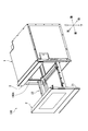
- FIG. 1 is a perspective view showing the appearance of the drawer type cooking cooker 100 according to the first embodiment.
- FIG. 2 is a right side view showing the drawer type cooking cooker 100 according to the first embodiment.
- FIG. 3 is a top view showing the drawer type cooking cooker 100 according to the first embodiment. More specifically, FIGS. 1 to 3 show a drawer type cooking cooker 100 in a state in which the drawer body 2 is pulled out. Further, FIG. 1 shows the appearance of the drawer-type cooking cooker 100 as viewed from above diagonally to the right.
- the drawer type cooking cooker 100 is an example of a cooking cooker.
- the drawer type cooking cooker 100 heats and cooks the object H to be heated.
- the object to be heated H is, for example, a food product.
- the drawer type cooking cooker 100 includes a heating cabinet 1, a drawer body 2, and an operation panel 3.
- the side on which the operation panel 3 of the drawer-type cooking cooker 100 is arranged is defined as the front side of the drawer-type cooking cooker 100, and the opposite side is defined as the rear side of the drawer-type cooking cooker 100.
- the right side when the drawer type cooking cooker 100 is viewed from the front side is defined as the right side of the drawer type cooking cooker 100
- the opposite side is defined as the left side of the drawer type cooking cooker 100.
- the side on which the operation panel 3 is arranged is the upper side of the drawer-type cooker 100
- the opposite side is the drawer-type cooker 100. Defined as the lower side. It should be noted that these orientations do not limit the orientation when the drawer type cooking cooker of the present invention is used.
- the heating chamber 1 is a box-shaped member. Specifically, the heating chamber 1 has a right outer wall 1G, a left outer wall 1H, a top outer wall 1J, a bottom outer wall 1F, and a back outer wall 1K.
- the heating cabinet 1 has a cooking chamber 100A inside.
- the cooking room 100A has a storage space 120 for accommodating the object to be heated H.
- the accommodation space 120 has a predetermined volume as a space capable of accommodating the object to be heated H.
- the cooking chamber 100A has a right wall 1A, a left wall 1B, a top wall 1C, a bottom wall 1D, and a back wall 1E.
- the shape of the cooking chamber 100A is, for example, a substantially rectangular parallelepiped.
- the material of the right wall 1A, the left wall 1B, the top wall 1C, the bottom wall 1D, and the back wall 1E is, for example, metal.
- the front side of the cooking chamber 100A is opened for taking in and out the object to be heated H.
- the heating chamber 1 further has a space between the bottom wall 1D and the bottom outer wall 1F.
- the heating chamber 1 further has a space between the right wall 1A and the right outer wall 1G.
- the heating chamber 1 further has a space between the left wall 1B and the left outer wall 1H.
- the heating chamber 1 further has a space between the top wall 1C and the top wall 1J.
- the heating chamber 1 further has a space between the back wall 1E and the back outer wall 1K.
- the operation panel 3 has an operation unit and a display unit.
- the operation unit accepts operations from the user.
- the operation unit includes various keys.
- the display unit displays various types of information.
- the display unit includes a liquid crystal panel.
- the operation panel 3 is located at the upper part of the front surface of the heating chamber 1.
- the drawer body 2 can be freely drawn with respect to the cooking chamber 100A. Specifically, the drawer body 2 can be pulled out and pulled in from the heating chamber 1. Specifically, the drawer body 2 has a door portion 21, a mounting portion 22, and a support portion 23. The door portion 21 can open and close the opening on the front side of the cooking chamber 100A.
- the door portion 21 is a substantially rectangular plate-shaped member.
- the door portion 21 has a front surface 21A and a rear surface 21B.
- the door portion 21 opens the opening on the front side of the cooking chamber 100A in a state where the drawer 2 is pulled out from the cooking chamber 100A.
- the door portion 21 closes the opening on the front side of the cooking chamber 100A in a state where the drawer 2 is pulled into the cooking chamber 100A. In the state where the drawer 2 is drawn into the cooking chamber 100A, the distance between the top wall 1C and the bottom wall 1D is shorter than the distance between the back wall 1E and the rear surface 21B.
- the mounting portion 22 can mount the object to be heated H.
- the mounting portion 22 is, for example, a plate-shaped member made of ceramics or glass.
- the support portion 23 is fixed to the rear surface 21B of the door portion 21 and supports the peripheral edge portion of the mounting portion 22 so that the mounting portion 22 is maintained horizontally.
- the material of the support portion 23 includes metal.
- the drawer body 2 further includes a pair of slide members 24 and a support member 25 in addition to the door portion 21, the support portion 23, and the mounting portion 22.
- the pair of slide members 24 regulate the moving direction of the drawer body 2 in the front-rear direction. In other words, the pair of slide members 24 determine the moving direction of the drawer body 2 in the front-rear direction.
- the pair of slide members 24 are fixed to the rear surface 21B of the door portion 21.
- the pair of slide members 24 has a right side slide member 241 and a left side slide member 242.
- Each of the right side slide member 241 and the left side slide member 242 is a member whose longitudinal direction is the front-rear direction.
- the right side slide member 241 and the left side slide member 242 face each other in the left-right direction.
- One end of the right slide member 241 is attached to the right edge of the rear surface 21B of the door 21.
- One end of the left slide member 242 is attached to the left edge of the rear surface 21B of the door 21.
- the heating chamber 1 further has a right side slide rail 11 and a left side slide rail 12.
- the right slide rail 11 is fixed in the space between the right wall 1A and the right outer wall 1G.
- the left slide rail 12 is fixed in the space between the left wall 1B and the left outer wall 1H.
- Each of the right side slide rail 11 and the left side slide rail 12 is a member whose longitudinal direction is the front-rear direction.
- the right side slide member 241 is slidably supported by the right side slide rail 11.
- the left side slide member 242 is slidably supported by the left side slide rail 12.
- the support member 25 supports the door portion 21. Specifically, the support member 25 regulates the moving direction of the drawer body 2 in the front-rear direction. In other words, the support member 25 determines the moving direction of the drawer body 2 in the front-rear direction. One end of the support member 25 is attached to the central portion of the rear surface 21B of the door portion 21 in the left-right direction and below the mounting portion 22.
- the support member 25 is a member whose longitudinal direction is the front-rear direction.
- the support member 25 has a rack portion.
- the rack portion has a plurality of teeth.
- the heating chamber 1 further has a drive mechanism 4.
- the drive mechanism 4 is housed in the space between the bottom wall 1D and the bottom outer wall 1F.
- the drive mechanism 4 has a drive motor 41, a pinion, and a drive rail 42.
- the drive rail 42 is fixed in the space between the bottom wall 1D and the bottom outer wall 1F.
- the drive rail 42 is a member whose longitudinal direction is the front-rear direction.
- the support member 25 is slidably supported by the drive rail 42.
- the pinion is attached to the tip of the drive motor 41.
- the pinion meshes with the rack portion of the support member 25. Then, as the pinion rotates, the support member 25 moves in the front-rear direction.
- the drive mechanism 4 may drive at least one of the support member 25, the right side slide member 241 and the left side slide member 242.
- the drive mechanism 4 may be located on the side of the cooking chamber 100A.
- FIGS. 1 to 5 are views showing a schematic cross section of the cooking chamber 100A according to the first embodiment. Specifically, FIG. 4 shows a cross section of the cooking chamber 100A cut along a plane orthogonal to the front-rear direction. FIG. 5 shows a cross section of the cooking chamber 100A cut along a plane orthogonal to the left-right direction.
- the drawer type cooking cooker 100 further includes a blower unit 14.
- the blower unit 14 supplies hot air F1 into the cooking chamber 100A.
- the blower portion 14 has a suction hole portion 14D and a blowout hole portion 14C.
- the suction hole portion 14D is located on a predetermined side of the cooking chamber 100A.
- the blowout hole portion 14C is located on a predetermined side of the cooking chamber 100A.
- the suction hole portion 14D is located in a predetermined direction D1 with respect to the accommodation space 120.
- the outlet hole portion 14C is located in the predetermined direction D1 with respect to the accommodation space 120.
- the predetermined direction D1 is, for example, along the upward direction in the vertical direction.
- the blower portion 14 is located above the accommodation space 120 via the top wall 1C.
- the suction hole portion 14D is located above the accommodation space 120.
- the outlet hole portion 14C is located above the accommodation space 120.
- the air blowing unit 14 sucks the air in the cooking chamber 100A through the suction hole 14D and blows the air into the cooking chamber 100A through the blowing hole 14C. Specifically, the blower unit 14 sucks the hot air F1 from the predetermined area EA in the accommodation space 120 and blows the hot air F1 to the predetermined area EA in the accommodation space 120.
- the predetermined area EA is, for example, a central area in the accommodation space 120.
- the central portion of the object to be heated H is arranged in the predetermined region EA.
- the suction hole portion 14D and the blowout hole portion 14C are located on the predetermined side of the cooking chamber 100A, the distance between the suction hole portion 14D and the blowout hole portion 14C is shortened. .. As a result, the circulation path of the hot air F1 is also shortened. Therefore, the time required to heat the predetermined region EA in the cooking chamber 100A by the hot air F1 can be shortened.
- the suction hole portion 14D and the blowout hole portion 14C are located above the accommodation space 120. Since the distance between the top wall 1C and the bottom wall 1D is short, the distance between the suction hole portion 14D and the predetermined region EA and the distance between the blowout hole portion 14C and the predetermined region EA are short. Therefore, the predetermined region EA in the cooking chamber 100A can be heated in a shorter time. In addition, the upper surface of the mounting portion 22 of the drawer body 2 can be heated in a shorter time.
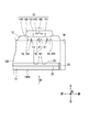
- FIG. 6A is a diagram showing a schematic cross section of the blower portion 14.
- the blower unit 14 further includes a heating chamber 14A, a second heater 141, a centrifugal fan 142, a drive unit 143, and a partition member 14B.
- the heating chamber 14A is, for example, a box-shaped member.
- the heating chamber 14A has a right wall 14A1, a left wall 14A2, a rear wall 14A3, and a front wall 14A4.
- the second heater 141 and the centrifugal fan 142 are housed in the heating chamber 14A.
- the second heater 141 heats the air in the heating chamber 14A to generate hot air F1.
- the shape of the second heater 141 is a ring when viewed from the upper side to the lower side.
- the second heater 141 is arranged along the outer circumference of the centrifugal fan 142.
- the drive unit 143 is located outside the heating chamber 14A.
- the drive unit 143 energizes the second heater 141 and drives the centrifugal fan 142.
- the drive unit 143 includes, for example, a motor and an energizing unit.
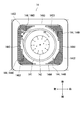
- FIG. 6B is a diagram showing a partition member 14B according to the first embodiment.
- the partition member 14B is located above the accommodation space 120. Specifically, the partition member 14B is located between the heating chamber 14A and the cooking chamber 100A.
- the partition member 14B is, for example, a metal plate-shaped member.
- the shape of the partition member 14B is, for example, a square when viewed from the lower side to the upper side.
- the partition member 14B is arranged at a substantially central portion of the top wall 1C.
- the suction hole portion 14D and the blowout hole portion 14C are arranged in the partition member 14B. Therefore, the suction hole portion 14D and the blowout hole portion 14C can be easily arranged above the accommodation space 120.
- the suction hole portion 14D is, for example, an aggregate of a plurality of punch holes 14Da.
- the blowout hole portion 14C is also, for example, an aggregate of a plurality of punch holes 14Ca.
- the punch hole 14Da is an example of a suction hole.
- the punch hole 14Ca is an example of a blowout hole.
- Each of the punch hole 14Da and the punch hole 14Ca is, for example, circular.
- the diameter of each of the punch hole 14Da and the punch hole 14Ca is, for example, 3.4 mm.
- the size of each of the punch hole 14Da and the punch hole 14Ca is small. As a result, it is possible to prevent tools and the like from being caught in each of the suction hole portion 14D and the blowout hole portion 14C when cleaning the inside of the cooking chamber 100A.
- the outlet hole portion 14C surrounds the suction hole portion 14D.
- the suction hole portion 14D is located at the central portion of the partition member 14B.
- the shape of the aggregate of the plurality of punch holes 14Da of the suction hole portion 14D is, for example, circular.
- the outlet hole portion 14C is formed along the outer circumference of the suction hole portion 14D.
- the shape of the aggregate of the plurality of punch holes 14Ca of the blowout hole portion 14C is, for example, an annular shape.
- the centrifugal fan 142 faces the cooking chamber 100A via the partition member 14B.
- the suction hole portion 14D faces the centrifugal fan 142.
- the blower unit 14 sucks the hot air F1 in the cooking chamber 100A into the heating chamber 14A through the suction hole portion 14D by the centrifugal fan 142.
- the hot air F1 sucked into the heating chamber 14A is heated by the second heater 141.
- the blower unit 14 blows the hot air F1 in the heating chamber 14A into the cooking chamber 100A through the blowout hole portion 14C by the centrifugal fan 142.
- the hot air F1 blown into the cooking chamber 100A moves downward.
- the hot air F1 that has reached the peripheral region of the predetermined region EA in the cooking chamber 100A moves toward, for example, the central region of the predetermined region EA, reverses the moving direction, and moves upward.
- the hot air F1 moving upward moves in the cooking chamber 100A.
- the hot air F1 is sucked into the heating chamber 14A again from the suction hole portion 14D. In this way, the blower unit 14 circulates the hot air F1 between the heating chamber 14A and the predetermined region EA in the cooking chamber 100A.
- the blowing hole portion 14C surrounds the suction hole portion 14D, the predetermined region EA in the cooking chamber 100A can be heated more uniformly.
- the upper surface of the mounting portion 22 of the drawer body 2 can be heated more uniformly.
- the drawer type cooking cooker 100 further includes a grill portion 16.
- the grill portion 16 has a first heater 161 and an energizing portion 162.
- the first heater 161 is located in the cooking chamber 100A and heats the object to be heated H.
- the first heater 161 is located in the upper part of the cooking chamber 100A.
- the first heater 161 has a substantially U-shape when viewed from the lower side to the upper side. In the first embodiment, three grill portions 16 are arranged.
- the first heater 161 is, for example, a sheathed heater. It is preferable that the position of the blowout hole portion 14C and the position of the first heater 161 overlap in the predetermined direction D1.
- the energizing portion 162 is located outside the left wall 1B.
- the energizing unit 162 energizes the first heater 161.
- the energized first heater 161 generates heat.
- the blower unit 14 sucks the hot air F1 in the cooking chamber 100A into the heating chamber 14A through the suction hole portion 14D by the centrifugal fan 142.
- the hot air F1 sucked into the heating chamber 14A is heated by the second heater 141.
- the blower unit 14 blows the hot air F1 in the heating chamber 14A into the cooking chamber 100A through the blowing hole portion 14C by the centrifugal fan 142.
- the hot air F1 blown into the cooking chamber 100A moves downward.
- the hot air F1 moving in the cooking chamber 100A is heated by the first heater 161. After that, the hot air F1 reaches a predetermined region EA in the cooking chamber 100A.
- the hot air F1 is heated not only by the second heater 141 but also by the first heater 161.
- the predetermined region EA in the cooking chamber 100A can be heated in a shorter time.
- the upper surface of the mounting portion 22 of the drawer body 2 can be heated in a shorter time.
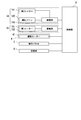
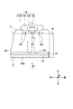
- FIG. 7 is a block diagram showing the configuration of the drawer type cooking cooker 100 according to the first embodiment. As shown in FIG. 7, the drawer type cooking cooker 100 further includes a control unit 5 and a storage unit 6.
- the drawer type cooking cooker 100 has a "first hot air circulation heating mode", a “second hot air circulation heating mode”, and a “grill heating mode” as cooking modes.
- the "first hot air circulation heating mode” is a mode in which the heated object H is cooked by directly blowing the hot air F1 onto the upper surface of the heated object H.
- the “second hot air circulation heating mode” is a mode in which hot air F1 is circulated in the cooking chamber 100A to preheat a predetermined region EA in the cooking chamber 100A in a short time.
- the "grill heating mode” is a mode in which the heated object H is mainly cooked by conducting the heat generated by the first heater 161 to the heated object H.
- the control unit 5 is a hardware circuit including a processor such as a CPU (Central Processing Unit).
- the control unit 5 controls the second heater 141, the drive unit 143, the energizing unit 162, the drive motor 41, the operation panel 3, and the storage unit 6 by executing the control program stored in the storage unit 6.
- a processor such as a CPU (Central Processing Unit).
- the control unit 5 controls the second heater 141, the drive unit 143, the energizing unit 162, the drive motor 41, the operation panel 3, and the storage unit 6 by executing the control program stored in the storage unit 6.
- the storage unit 6 is composed of a RAM (Random Access Memory) and a ROM (Read Only Memory).
- the storage unit 6 stores a control program for controlling the operation of each part of the drawer-type cooking cooker 100.
- the storage unit 6 stores the setting information input by operating the operation panel 3.
- FIG. 8 is a diagram showing the appearance of a cabinet 200 to which the drawer-type cooking cooker 100 according to the present embodiment is mounted.
- the drawer type cooking cooker 100 is installed by being built in the cabinet 200.
- the cabinet 200 has an upper wall 200A, a lower wall 200B, a right wall 200C, a left wall 200D, and a rear wall 200E.
- the upper wall 200A, the lower wall 200B, the right wall 200C, the left wall 200D and the rear wall 200E form an accommodating portion 200F.
- the accommodating portion 200F is a rectangular parallelepiped space in which the drawer type cooking cooker 100 is attached.
- control unit 5 controls the rotation speed of the centrifugal fan 142.
- control unit 5 controls the drive unit 143 so as to increase or decrease the rotation speed of the centrifugal fan 142.
- FIG. 9 is a view showing a cross section of a cooking chamber 100A cut along a plane orthogonal to the front-rear direction.
- the drive unit 143 drives the centrifugal fan 142 so that the rotation speed of the centrifugal fan 142 is slower than the rotation speed of the centrifugal fan 142 shown in FIG.
- the reach distance indicates, for example, the distance that the hot air F1 reaches the position farthest from the partition member 14B.
- control unit 5 controls the rotation direction of the centrifugal fan 142. Specifically, the control unit 5 controls the drive unit 143 so that the rotation direction of the centrifugal fan 142 is clockwise R1 or counterclockwise R2.
- the blower portion 14 will be described in detail with reference to FIGS. 10A and 10B. As shown in FIGS. 10A and 10B, the blower portion 14 further includes a plurality of partition plates 144. Each of the plurality of partition plates 144 stands upright from the upper surface of the partition member 14B.
- the plurality of partition plates 144 includes a first partition plate 144A, a second partition plate 144B, a third partition plate 144C, and a fourth partition plate 144D.
- the first partition plate 144A is located in the rear right region of the first partition plate 144A.
- the second partition plate 144B is located in the front right region of the first partition plate 144A.
- the third partition plate 144C is located in the front left region of the first partition plate 144A.
- the fourth partition plate 144D is located in the rear left region of the first partition plate 144A.
- the first partition plate 144A has a first plate and a second plate.
- the first plate is arranged parallel to the rear wall 14A3 at a predetermined distance from the rear wall 14A3.
- the right end portion of the first plate is connected to the right wall 14A1.
- the second plate is arranged parallel to the right wall 14A1 at a predetermined interval from the right wall 14A1.
- the left end portion of the first plate and the rear end portion of the second plate are connected. That is, the shape of the first partition plate 144A is substantially L-shaped when viewed from the upper side to the lower side.
- the second partition plate 144B is arranged in parallel with the right wall 14A1 at a predetermined distance from the right wall 14A1. Then, the front end portion of the second partition plate 144B is connected to the front wall 14A4.
- the third partition plate 144C has a first plate and a second plate.
- the first plate is arranged parallel to the front wall 14A4 at a predetermined distance from the front wall 14A4.
- the left end portion of the first plate is connected to the left wall 14A2.
- the second plate is arranged parallel to the left wall 14A2 at a predetermined distance from the left wall 14A2.
- the right end portion of the first plate and the front end portion of the second plate are connected. That is, the shape of the third partition plate 144C is substantially L-shaped when viewed from the upper side to the lower side.
- the fourth partition plate 144D is arranged parallel to the left wall 14A2 at a predetermined distance from the left wall 14A2. Then, the rear end portion of the fourth partition plate 144D is connected to the rear wall 14A3.
- the control unit 5 controls the drive unit 143 so that the rotation direction of the centrifugal fan 142 is clockwise R1.
- the blower unit 14 sucks the hot air F1 in the cooking chamber 100A into the heating chamber 14A through the suction hole portion 14D by the centrifugal fan 142.
- the hot air F1 sucked into the heating chamber 14A is heated by the second heater 141.
- the blower unit 14 blows the hot air F1 in the heating chamber 14A into the cooking chamber 100A through the outlet hole portion 14C by the centrifugal fan 142.
- the hot air F1 is blown into the cooking chamber 100A from the four corners of the partition member 14B.
- it is blown into the cooking chamber 100A from a plurality of punch holes 14Ca located in the first region 14C1, the second region 14C2, the third region 14C3, and the fourth region 14C4.
- the first region 14C1, the second region 14C2, the third region 14C3, and the fourth region 14C4 are clocks of the first partition plate 144A, the second partition plate 144B, the third partition plate 144C, and the fourth partition plate 144D, respectively. It is located on the opposite side of the rotation R1.
- the control unit 5 controls the drive unit 143 so that the rotation direction of the centrifugal fan 142 is counterclockwise R2.
- the blower unit 14 sucks the hot air F1 in the cooking chamber 100A into the heating chamber 14A through the suction hole portion 14D by the centrifugal fan 142.
- the hot air F1 sucked into the heating chamber 14A is heated by the second heater 141.
- the blower unit 14 blows the hot air F1 in the heating chamber 14A into the cooking chamber 100A through the outlet hole portion 14C by the centrifugal fan 142.
- the hot air F1 is blown into the cooking chamber 100A mainly from the right side region and the left side region of the partition member 14B.
- the hot air F1 is blown into the cooking chamber 100A from a plurality of punch holes 14Ca located in the fifth region 14C5, the sixth region 14C6, the seventh region 14C7, and the eighth region 14C8.
- the fifth region 14C5 and the sixth region 14C6 are surrounded by the first partition plate 144A and the third partition plate 144C, respectively.
- the rotation direction of the centrifugal fan 142 is controlled. As a result, since the blowing direction and the blowing region of the hot air F1 can be changed, it is possible to reduce the local heating of the object H to be heated, and the uneven heating of the object H to be heated is reduced. be able to.
- FIG. 11 is a flowchart showing an example of processing by the control unit 5.
- the process of the control unit 5 includes steps S101 to S108.
- the control unit 5 controls the blower unit 14 based on the "first hot air circulation heating mode" input on the operation panel 3 and the information of the object to be heated H.
- the storage unit 6 stores in advance the control method of the blower unit 14. Specifically, in the control method, the information of the object to be heated H, the rotation direction of the blower unit 14, the rotation speed of the blower unit 14, and the predetermined time are associated with each other.
- step S101 the control unit 5 determines the rotation direction of the centrifugal fan 142. If the control unit 5 determines that it is clockwise R1, the process proceeds to step S102. On the other hand, if the control unit 5 determines that it is counterclockwise R2, the process proceeds to step S103.
- step S102 the drive unit 143 drives the centrifugal fan 142 clockwise R1. Then, the process proceeds to step S104.
- step S103 the drive unit 143 drives the centrifugal fan 142 in a counterclockwise direction R2. Then, the process proceeds to step S104.
- step S104 the control unit 5 determines the rotation speed of the centrifugal fan 142. If the control unit 5 determines that the speed is the first speed, the process proceeds to step S105. On the other hand, when the control unit 5 determines that the speed is the second speed, the process proceeds to step S106. The second speed is slower than the first speed.
- step S105 the drive unit 143 drives the centrifugal fan 142 at the first speed. Then, the process proceeds to step S107.
- step S106 the drive unit 143 drives the centrifugal fan 142 at the second speed. Then, the process proceeds to step S107.
- step S107 the control unit 5 determines whether or not a predetermined time has elapsed. If the control unit 5 determines that the predetermined time has not elapsed, the process returns to step S107. On the other hand, when the control unit 5 determines that the predetermined time has elapsed, the process proceeds to step S108.
- step S108 the control unit 5 determines whether or not to end. If the control unit 5 determines that the process has not ended, the process returns to step S101. On the other hand, when the control unit 5 determines that it is finished, the process is finished.
- the rotation direction and the rotation speed of the centrifugal fan 142 are controlled. As a result, a desired region in the cooking chamber 100A can be effectively heated.
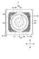
- FIG. 12 is a diagram showing a partition member 214B and a first heater 261 according to the second embodiment.
- the arrangement region of the plurality of punch holes 14Ca and the shape of the first heater 261 are different from those of the first embodiment.
- the blower unit 14 has a heating chamber 14A, a centrifugal fan 142, a drive unit 143, a partition member 214B, and a second heater 141.
- the outlet hole portion 214C surrounds the suction hole portion 214D.
- the suction hole portion 214D is located at the central portion of the partition member 214B.
- the shape of the aggregate of the plurality of punch holes 214Da of the suction hole portion 124D is, for example, circular.
- the outlet hole portion 214C is formed along the outer circumference of the suction hole portion 214D.
- the shape of the aggregate of the plurality of punch holes 214Ca of the blowout hole portion 214C is, for example, a square ring.
- the grill portion 216 has a first heater 261 and an energizing portion 262.
- the first heater 261 has a substantially square ring shape when viewed from the lower side to the upper side. Specifically, when viewed from the lower side to the upper side, it is preferable that the position of the blowout hole portion 214C and the position of the first heater 261 overlap. More specifically, when viewed from the lower side to the upper side, the positions of at least a part of the punch holes 214Ca among the plurality of punch holes 214Ca overlap with the positions of the first heater 261. Then, the control unit 5 controls the energizing unit 262 so that the first heater 261 reaches a predetermined temperature.
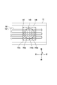
- FIG. 13 shows a cross section of the cooking chamber 100A cut along a plane orthogonal to the left-right direction.
- the blower unit 14 sucks the hot air F1 in the cooking chamber 100A into the heating chamber 14A through the plurality of punch holes 214Ca by the centrifugal fan 142.
- the blower unit 14 blows hot air F1 in the heating chamber 14A toward the first heater 261 through a plurality of punch holes 214Ca by a centrifugal fan 142.
- At least a part of the hot air F1 hits the first heater 261.
- the blowing direction of at least a part of the hot air F1 changes, and the hot air F1 is dispersed.
- the drawer type cooking cooker 100 of the present invention at least a part of the hot air F1 hits the first heater 261 and is heated. As a result, the hot air F1 is dispersed, and uneven heating of the object to be heated H can be reduced.
- FIG. 14 is a diagram showing a partition member 314B and a first heater 361 according to the third embodiment.
- the third embodiment is different from the first embodiment in that the blowout hole portion 314C is an aggregate of a large number of punch holes 14Ca.
- the blower unit 14 includes a heating chamber 14A, a centrifugal fan 142, a drive unit 143, a partition member 314B, and a second heater 141.
- the outlet hole portion 314C surrounds the suction hole portion 314D. Specifically, the suction hole portion 314D is located at the central portion of the partition member 314B.
- the shape of the aggregate of a large number of punch holes 314Da of the suction hole portion 314D is, for example, circular.
- the outlet hole portion 314C is formed along the outer circumference of the suction hole portion 314D.
- the shape of the aggregate of a large number of punch holes 314Ca of the blowout hole portion 314C is, for example, an annular shape. Then, the control unit 5 controls the energizing unit 162 so that the first heater 361 reaches a predetermined temperature.
- the grill portion 316 has a first heater 361 and an energizing portion 362.
- the first heater 361 has a substantially U shape when viewed from the lower side to the upper side. More specifically, when viewed from the lower side to the upper side, it is preferable that the position of the outlet hole portion 314C and the position of the suction hole portion 314D and the position of the first heater 361 overlap. More specifically, when viewed from the lower side to the upper side, the positions of at least a part of the punch holes 314Ca among the plurality of punch holes 314Ca and the positions of the first heater 361 overlap. Further, when viewed from the lower side to the upper side, the positions of at least a part of the punch holes 314Da among the plurality of punch holes 314Da and the positions of the first heater 361 overlap.
- FIG. 15 shows a cross section of the cooking chamber 100A cut along a plane orthogonal to the left-right direction.
- the blower unit 14 sucks the hot air F1 in the cooking chamber 100A into the heating chamber 14A through a large number of punch holes 314Ca by the centrifugal fan 142.
- the first heater 361 At least a part of the hot air F1 hits the first heater 361.
- the blower unit 14 blows the hot air F1 in the heating chamber 14A toward the first heater 361 through a large number of punch holes 314Ca by the centrifugal fan 142.
- At least a part of the hot air F1 hits the first heater 361.
- the blowing direction of at least a part of the hot air F1 changes, and the hot air F1 is dispersed.
- the drawer type cooking cooker 100 of the present invention at least a part of the hot air F1 hits the first heater 361 and is heated.
- the hot air F1 is dispersed, and uneven heating of the object to be heated H can be reduced.
- the temperature of the hot air F1 can be maintained at a high temperature, and the object to be heated H can be cooked satisfactorily.
- FIG. 16 shows a cross section of the cooking chamber 100A cut along a plane orthogonal to the front-rear direction.
- the shape of the support portion 423 of the drawer body 402 is different from that of the first embodiment.
- the drawer body 402 has a door portion 21, a mounting portion 422, and a support portion 423.
- the support portion 423 is an example of a side wall portion.
- the support portion 423 is erected on the peripheral edge portion of the mounting portion 422.
- the upper end of the support portion 423 has a protruding portion 423a projecting outward of the mounting portion 422.
- the upper end of the support portion 423 is preferably inclined toward the mounting portion 422.
- the blowout hole portion 14C is located inside the support portion 423. Therefore, it is possible to prevent the hot air F1 from turning to the outside of the drawer body 402, and it is possible to increase the thermal efficiency with respect to the object to be heated H.
- the blower unit 14 sucks the hot air F1 in the cooking chamber 100A into the heating chamber 14A through the suction hole portion 314D by the centrifugal fan 142.
- the blower unit 14 blows the hot air F1 in the heating chamber 14A into the cooking chamber 100A through the blowing hole portion 314C by the centrifugal fan 142.
- the hot air F1 blown into the cooking chamber 100A moves downward.
- the hot air F1 moving in the cooking chamber 100A is heated by the first heater 161.
- the air blown toward the first heater 161 is guided to the central portion of the mounting portion 422 by the protruding portion 423a. After that, the hot air F1 reaches a predetermined region EA in the cooking chamber 100A.
- the upper surface of the mounting portion 422 of the drawer body 402 can be heated in a shorter time.
- FIG. 1 to 16 The embodiment of the present invention has been described above with reference to the drawings (FIGS. 1 to 16). However, the present invention is not limited to the above-described embodiment, and can be implemented in various embodiments without departing from the gist thereof.
- the drawings are schematically shown mainly for each component for easy understanding, and the thickness, length, number, etc. of each component shown are different from the actual ones for the convenience of drawing creation. .. Further, the material, shape, dimensions, etc. of each component shown in the above embodiment are merely examples, and are not particularly limited, and various changes can be made without substantially deviating from the effects of the present invention. is there.
- the drawer type cooking cooker 100 includes a blower unit 14, but the present invention is not limited thereto.
- the drawer type cooking cooker 100 may further include a blowing unit different from the blowing unit 14.
- the drawer type cooking cooker 100 may include a microwave supply unit that supplies microwaves into the cooking room 100A.
- each of the blow-out hole portion 14C and the suction hole portion 14D is an aggregate of a plurality of punch holes 14Ca and 14Da. Not limited.
- each of the blowout hole portion 14C and the suction hole portion 14D may be one opening, a plurality of slit holes, or a net shape.
- the predetermined direction D1 is along the upward direction in the vertical direction, but the present invention is not limited thereto.
- it may be along the horizontal direction.
- the suction hole portion 14D and the blowout hole portion 14C may be arranged on the right wall 1A, the left wall 1B, and the back wall 1E.
- the drawer type cooking cooker 100 includes a drawer body 2, but the present invention is not limited thereto.
- the bottom wall 1D may be provided with a rotary table without the drawer body 2.
- the present invention is useful, for example, in the field of cookers.
Landscapes
- Engineering & Computer Science (AREA)
- Chemical & Material Sciences (AREA)
- Combustion & Propulsion (AREA)
- Mechanical Engineering (AREA)
- General Engineering & Computer Science (AREA)
- Physics & Mathematics (AREA)
- Electromagnetism (AREA)
- Baking, Grill, Roasting (AREA)
- Electric Stoves And Ranges (AREA)
Abstract
Description
図1~図3を参照して、実施形態1に係る引出し式加熱調理器100について説明する。図1は、実施形態1に係る引出し式加熱調理器100の外観を示す斜視図である。図2は、実施形態1に係る引出し式加熱調理器100を示す右側面図である。図3は、実施形態1に係る引出し式加熱調理器100を示す上面図である。詳しくは、図1~図3は、引出し体2を引出した状態の引出し式加熱調理器100を示す。また、図1は、引出し式加熱調理器100を右斜め前の上方から視た外観を示す。引出し式加熱調理器100は、加熱調理器の一例である。
次に、図12を参照して、実施形態2に係る引出し式加熱調理器100について説明する。図12は、実施形態2に係る仕切り部材214B及び第1ヒーター261を示す図である。実施形態2では、複数のパンチ孔14Caの配置領域と第1ヒーター261の形状とが実施形態1と相違する。
次に、図14を参照して、実施形態3に係る引出し式加熱調理器100について説明する。図14は、実施形態3に係る仕切り部材314B及び第1ヒーター361を示す図である。実施形態3では、吹出孔部314Cが多数のパンチ孔14Caの集合体である点で実施形態1と相違する。
次に、図16を参照して、実施形態4に係る引出し式加熱調理器100について説明する。図16は、前後方向に直交する面で切断した加熱調理室100Aの断面を示す。実施形態4では、引出し体402の支持部423の形状が実施形態1と相違する。
14 送風部
14B 仕切り部材
14C 吹出孔部
14D 吸込孔部
141 第2ヒーター
142 遠心ファン
100 引出し式加熱調理器
100A 加熱調理室
120 収容空間
Claims (10)
- 被加熱物を収容する加熱調理室と、
前記加熱調理室内に熱風を供給する送風部と、
前記加熱調理室内に位置して、前記被加熱物を加熱する第1ヒーターと
を備え、
前記送風部は、
前記加熱調理室の所定側に位置する吸込孔部と、
前記所定側に位置する吹出孔部と
を有し、
前記送風部は、
前記吸込孔部を通して前記加熱調理室内の空気を吸込むとともに、前記吹出孔部を通して空気を前記第1ヒーターに向かって吹出す、加熱調理器。 - 前記加熱調理室は、前記被加熱物を収容する収容空間を有し、
前記吸込孔部は、前記加熱調理室に対して所定方向に位置し、
前記吹出孔部は、前記加熱調理室に対して前記所定方向に位置し、
前記吹出孔部の少なくとも一部の位置と前記第1ヒーターの位置とが前記所定方向に重なる、請求項1に記載の加熱調理器。 - 前記吹出孔部は、前記吸込孔部を囲む、請求項1又は請求項2に記載の加熱調理器。
- 前記吸込孔部は、複数の吸込孔を有し、
前記吹出孔部は、複数の吹出孔を有する、請求項1から請求項3のいずれか1項に記載の加熱調理器。 - 前記送風部は、仕切り部材を更に有し、
前記吸込孔部及び前記吹出孔部は、前記仕切り部材に配置される、請求項1から請求項4のいずれか1項に記載の加熱調理器。 - 前記仕切り部材は、前記加熱調理室の天壁に配置される、請求項5に記載の加熱調理器。
- 前記送風部は、前記仕切り部材を介して前記加熱調理室に対向する遠心ファンを更に有し、
前記吸込孔部は、前記遠心ファンに対向する、請求項5又は請求項6に記載の加熱調理器。 - 前記送風部を制御する制御部を更に備え、
前記制御部は、前記遠心ファンの回転速度を制御する、請求項7に記載の加熱調理器。 - 前記送風部を制御する制御部を更に備え、
前記制御部は、前記遠心ファンの回転方向を制御する、請求項7に記載の加熱調理器。 - 前記加熱調理室に対して引出し自在である引出し体を更に備え、
前記引出し体は、
前記被加熱物を載置する載置部と、
前記載置部の周縁部に立設された側壁部と
を有し、
前記吹出孔部は、前記側壁部よりも内側に配置され、
前記側壁部の上端は、前記載置部の外側に向かって突出する突出部を有する、請求項1から請求項9のいずれか1項に記載の加熱調理器。
Priority Applications (5)
| Application Number | Priority Date | Filing Date | Title |
|---|---|---|---|
| EP20846282.0A EP4006419A4 (en) | 2019-07-31 | 2020-03-16 | HEATING STOVE |
| US17/631,376 US20220325903A1 (en) | 2019-07-31 | 2020-03-16 | Heating cooking apparatus |
| CA3165750A CA3165750A1 (en) | 2019-07-31 | 2020-03-16 | Heating cooking apparatus |
| JP2021536606A JPWO2021019824A1 (ja) | 2019-07-31 | 2020-03-16 | |
| CN202080053409.3A CN114174724A (zh) | 2019-07-31 | 2020-03-16 | 加热烹调器 |
Applications Claiming Priority (2)
| Application Number | Priority Date | Filing Date | Title |
|---|---|---|---|
| JP2019141448 | 2019-07-31 | ||
| JP2019-141448 | 2019-07-31 |
Publications (1)
| Publication Number | Publication Date |
|---|---|
| WO2021019824A1 true WO2021019824A1 (ja) | 2021-02-04 |
Family
ID=74228798
Family Applications (1)
| Application Number | Title | Priority Date | Filing Date |
|---|---|---|---|
| PCT/JP2020/011444 WO2021019824A1 (ja) | 2019-07-31 | 2020-03-16 | 加熱調理器 |
Country Status (6)
| Country | Link |
|---|---|
| US (1) | US20220325903A1 (ja) |
| EP (1) | EP4006419A4 (ja) |
| JP (1) | JPWO2021019824A1 (ja) |
| CN (1) | CN114174724A (ja) |
| CA (1) | CA3165750A1 (ja) |
| WO (1) | WO2021019824A1 (ja) |
Citations (4)
| Publication number | Priority date | Publication date | Assignee | Title |
|---|---|---|---|---|
| JPS56149804U (ja) * | 1980-04-10 | 1981-11-10 | ||
| JP2008229152A (ja) * | 2007-03-22 | 2008-10-02 | Toshiba Corp | 複合加熱調理器 |
| JP2016056981A (ja) * | 2014-09-08 | 2016-04-21 | シャープ株式会社 | 加熱調理器 |
| JP2018179381A (ja) * | 2017-04-11 | 2018-11-15 | 日立アプライアンス株式会社 | 加熱調理器 |
Family Cites Families (12)
| Publication number | Priority date | Publication date | Assignee | Title |
|---|---|---|---|---|
| US2957067A (en) * | 1958-08-14 | 1960-10-18 | Philco Corp | Appliance units |
| JPS6116637Y2 (ja) * | 1980-05-28 | 1986-05-22 | ||
| JPS57166427A (en) * | 1981-04-03 | 1982-10-13 | Matsushita Electric Ind Co Ltd | Heating cooker |
| JPS61143623A (ja) * | 1984-12-18 | 1986-07-01 | Matsushita Electric Ind Co Ltd | 高周波加熱装置 |
| DE19828640A1 (de) * | 1998-06-26 | 1999-12-30 | Bsh Bosch Siemens Hausgeraete | Backofen mit eigenbeheiztem Gargutträger |
| KR100367584B1 (ko) * | 1999-06-28 | 2003-01-10 | 엘지전자 주식회사 | 전자 레인지의 히팅장치 |
| JP4472412B2 (ja) * | 2004-04-22 | 2010-06-02 | パナソニック株式会社 | 加熱調理器 |
| JP6312294B2 (ja) * | 2012-12-19 | 2018-04-18 | アイリスオーヤマ株式会社 | 加熱調理器 |
| JP2015010743A (ja) * | 2013-06-27 | 2015-01-19 | シャープ株式会社 | 加熱調理装置 |
| CN203642276U (zh) * | 2013-12-11 | 2014-06-11 | 广东美的厨房电器制造有限公司 | 微波炉抽屉和微波炉 |
| WO2016031737A1 (ja) * | 2014-08-29 | 2016-03-03 | シャープ株式会社 | 加熱調理器 |
| CN208909889U (zh) * | 2018-06-28 | 2019-05-31 | 佛山市顺德区美的电热电器制造有限公司 | 烘焙器具 |
-
2020
- 2020-03-16 CA CA3165750A patent/CA3165750A1/en active Pending
- 2020-03-16 EP EP20846282.0A patent/EP4006419A4/en active Pending
- 2020-03-16 US US17/631,376 patent/US20220325903A1/en active Pending
- 2020-03-16 WO PCT/JP2020/011444 patent/WO2021019824A1/ja unknown
- 2020-03-16 CN CN202080053409.3A patent/CN114174724A/zh active Pending
- 2020-03-16 JP JP2021536606A patent/JPWO2021019824A1/ja active Pending
Patent Citations (4)
| Publication number | Priority date | Publication date | Assignee | Title |
|---|---|---|---|---|
| JPS56149804U (ja) * | 1980-04-10 | 1981-11-10 | ||
| JP2008229152A (ja) * | 2007-03-22 | 2008-10-02 | Toshiba Corp | 複合加熱調理器 |
| JP2016056981A (ja) * | 2014-09-08 | 2016-04-21 | シャープ株式会社 | 加熱調理器 |
| JP2018179381A (ja) * | 2017-04-11 | 2018-11-15 | 日立アプライアンス株式会社 | 加熱調理器 |
Non-Patent Citations (1)
| Title |
|---|
| See also references of EP4006419A4 * |
Also Published As
| Publication number | Publication date |
|---|---|
| EP4006419A4 (en) | 2022-09-14 |
| CA3165750A1 (en) | 2021-02-04 |
| CN114174724A (zh) | 2022-03-11 |
| EP4006419A1 (en) | 2022-06-01 |
| JPWO2021019824A1 (ja) | 2021-02-04 |
| US20220325903A1 (en) | 2022-10-13 |
Similar Documents
| Publication | Publication Date | Title |
|---|---|---|
| WO2021019825A1 (ja) | 加熱調理器 | |
| WO2021019824A1 (ja) | 加熱調理器 | |
| WO2021157560A1 (ja) | 加熱調理器 | |
| WO2021020390A1 (ja) | 加熱調理器 | |
| WO2021020389A1 (ja) | 加熱調理器 | |
| US11825586B2 (en) | Heating cooking apparatus | |
| WO2022154117A1 (ja) | 加熱調理器 | |
| WO2021033687A1 (ja) | 引出し式加熱調理器 | |
| WO2021157559A1 (ja) | 加熱調理器 | |
| WO2022113998A1 (ja) | 加熱調理器 | |
| WO2021020345A1 (ja) | 加熱調理器 | |
| WO2022124299A1 (ja) | 加熱調理器 | |
| WO2021020343A1 (ja) | 加熱調理器 | |
| WO2021060344A1 (ja) | 加熱調理器及びビルトイン式加熱調理システム | |
| JPH08200684A (ja) | 加熱調理器 | |
| JP2000039153A (ja) | 加熱調理器 | |
| JP2003185141A (ja) | 加熱調理装置 |
Legal Events
| Date | Code | Title | Description |
|---|---|---|---|
| 121 | Ep: the epo has been informed by wipo that ep was designated in this application |
Ref document number: 20846282 Country of ref document: EP Kind code of ref document: A1 |
|
| ENP | Entry into the national phase |
Ref document number: 2021536606 Country of ref document: JP Kind code of ref document: A |
|
| ENP | Entry into the national phase |
Ref document number: 3165750 Country of ref document: CA |
|
| NENP | Non-entry into the national phase |
Ref country code: DE |
|
| ENP | Entry into the national phase |
Ref document number: 2020846282 Country of ref document: EP Effective date: 20220228 |