WO2022154117A1 - 加熱調理器 - Google Patents
加熱調理器 Download PDFInfo
- Publication number
- WO2022154117A1 WO2022154117A1 PCT/JP2022/001366 JP2022001366W WO2022154117A1 WO 2022154117 A1 WO2022154117 A1 WO 2022154117A1 JP 2022001366 W JP2022001366 W JP 2022001366W WO 2022154117 A1 WO2022154117 A1 WO 2022154117A1
- Authority
- WO
- WIPO (PCT)
- Prior art keywords
- heater
- cooking
- cooking chamber
- temperature
- control unit
- Prior art date
Links
- 238000010411 cooking Methods 0.000 claims abstract description 240
- 238000000034 method Methods 0.000 claims description 21
- 238000001514 detection method Methods 0.000 claims description 13
- 238000005192 partition Methods 0.000 description 26
- 238000010438 heat treatment Methods 0.000 description 22
- 230000002093 peripheral effect Effects 0.000 description 16
- 230000004308 accommodation Effects 0.000 description 15
- 238000007664 blowing Methods 0.000 description 8
- 238000010586 diagram Methods 0.000 description 7
- 230000006870 function Effects 0.000 description 7
- 239000000463 material Substances 0.000 description 5
- 238000009423 ventilation Methods 0.000 description 5
- 239000002184 metal Substances 0.000 description 4
- 238000013021 overheating Methods 0.000 description 4
- 206010037660 Pyrexia Diseases 0.000 description 3
- 238000004140 cleaning Methods 0.000 description 2
- 238000004904 shortening Methods 0.000 description 2
- 229920003002 synthetic resin Polymers 0.000 description 2
- 239000000057 synthetic resin Substances 0.000 description 2
- 239000000919 ceramic Substances 0.000 description 1
- 230000000694 effects Effects 0.000 description 1
- 239000011521 glass Substances 0.000 description 1
- 238000009413 insulation Methods 0.000 description 1
- 230000001678 irradiating effect Effects 0.000 description 1
- 239000004973 liquid crystal related substance Substances 0.000 description 1
- 229910052755 nonmetal Inorganic materials 0.000 description 1
- -1 polybutylene terephthalate Polymers 0.000 description 1
- 229920001707 polybutylene terephthalate Polymers 0.000 description 1
Images


Classifications
-
- F—MECHANICAL ENGINEERING; LIGHTING; HEATING; WEAPONS; BLASTING
- F24—HEATING; RANGES; VENTILATING
- F24C—DOMESTIC STOVES OR RANGES ; DETAILS OF DOMESTIC STOVES OR RANGES, OF GENERAL APPLICATION
- F24C15/00—Details
- F24C15/32—Arrangements of ducts for hot gases, e.g. in or around baking ovens
- F24C15/322—Arrangements of ducts for hot gases, e.g. in or around baking ovens with forced circulation
- F24C15/325—Arrangements of ducts for hot gases, e.g. in or around baking ovens with forced circulation electrically-heated
-
- F—MECHANICAL ENGINEERING; LIGHTING; HEATING; WEAPONS; BLASTING
- F24—HEATING; RANGES; VENTILATING
- F24C—DOMESTIC STOVES OR RANGES ; DETAILS OF DOMESTIC STOVES OR RANGES, OF GENERAL APPLICATION
- F24C7/00—Stoves or ranges heated by electric energy
- F24C7/08—Arrangement or mounting of control or safety devices
- F24C7/087—Arrangement or mounting of control or safety devices of electric circuits regulating heat
Definitions
- the present invention relates to a cooking device.
- Patent Document 1 discloses a drawer-type cooking cooker.
- the drawer-type cooker disclosed in Patent Document 1 includes a cooker main body and a drawer.
- the cooking cooker body has a cooking chamber.
- the drawer can be pulled out from the state of being housed in the cooking chamber toward the outside of the cooking cooker body.
- the heating function of the drawer-type cooking cooker disclosed in Patent Document 1 includes a microwave heating function and a high-speed hot air heating function.
- the microwave heating function is a function of irradiating a microwave to an object to be heated.
- the high-speed hot air heating function is a function of blowing hot air from the ceiling outlet and the side outlet toward the object to be heated and sucking the hot air from the side suction port.
- the ceiling outlet is formed on the top wall of the cooking room.
- the side outlet is formed on the left side wall of the cooking chamber.
- the side suction port is formed on the side wall on the back side of the cooking chamber.
- the object to be heated may be cooked after preheat-treating the cooking chamber.
- the drawer type cooking cooker there is room for further shortening the cooking period for cooking the object to be cooked in the preheat-treated cooking chamber.
- an object of the present invention is to provide a cooking cooker capable of shortening the cooking period for cooking an object to be cooked in a cooking chamber.
- the cooking cooker includes a cooking room, a first heater, a first fan, a second heater, a second fan, and a control unit.
- the cooking room accommodates the object to be heated.
- the first heater heats the first air.
- the first fan blows the first air heated by the first heater into the cooking chamber.
- the second heater heats the second air.
- the second fan blows the second air heated by the second heater into the cooking chamber.
- the control unit controls the first heater, the first fan, the second heater, and the second fan.
- the control unit stops energization of the first heater and energizes the second heater before notifying the end of the preheat treatment.
- the preheat treatment indicates a treatment in which the temperature in the cooking chamber exceeds the threshold temperature at least once before the object to be heated is housed in the cooking chamber.
- the cooking period for cooking the object to be heated in the cooking room can be shortened.
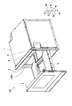
- FIG. 1 is a perspective view showing a drawer type cooking cooker 100.
- FIG. 2 is a right side view showing the drawer type cooking cooker 100.
- FIG. 3 is a top view showing a drawer type cooking cooker 100.
- FIGS. 1 to 3 show a drawer type cooking cooker 100 in a state in which the drawer body 2 is pulled out.
- FIG. 1 shows the appearance of the drawer-type cooking cooker 100 as viewed from above diagonally to the right.
- the drawer type cooking cooker 100 is an example of a "cooking cooker".
- the drawer type cooker 100 heats and cooks the object H to be heated.
- the object to be heated H is, for example, food.
- the drawer-type cooking cooker 100 includes a heating cabinet 1, a drawer 2, an operation panel 3, and a cooking chamber 100A.
- the side on which the operation panel 3 of the drawer-type cooker 100 is arranged is defined as the front side of the drawer-type cooker 100, and the opposite side (rear side) is defined as the rear side of the drawer-type cooker 100. do.
- the right side when the drawer type cooking cooker 100 is viewed from the front side is defined as the right side of the drawer type cooking cooker 100
- the opposite side is defined as the left side of the drawer type cooking cooker 100.
- the side on which the operation panel 3 is arranged is the upper side of the drawer-type cooking cooker 100
- the opposite side (bottom side) is the drawer-type heating. It is defined as the lower side of the cooker 100. It should be noted that these orientations do not limit the orientation when the drawer type cooking cooker 100 of the present invention is used.
- the heating chamber 1 is a box-shaped member. Specifically, the heating chamber 1 has a right outer wall 1G, a left outer wall 1H, a top outer wall 1J, a bottom outer wall 1F, and a back outer wall 1K. Then, the heating chamber 1 accommodates the cooking chamber 100A.
- the drawer 2 is capable of placing the object H to be heated and pulling it out in the first direction D1 with respect to the cooking chamber 100A.
- the first direction D1 is the forward direction.
- the third direction D3 intersects with the first direction D1.
- the third direction D3 is orthogonal to the first direction D1.
- the third direction D3 is the upward direction.
- the drawer 2 has a lid portion 21, a mounting portion 22, and a support portion 23.
- the cooking room 100A has a storage space 120 for accommodating the object to be heated H.
- the shape of the cooking chamber 100A is, for example, a substantially rectangular cuboid.
- the cooking chamber 100A includes a pair of side wall portions 10, a back wall 1E, and an opening 100B.
- the back wall 1E intersects the first direction D1.
- the opening 100B faces the back wall 1E.
- the opening 100B opens toward the first direction D1.
- the opening 100B communicates with the outside of the cooking chamber 100A.
- the pair of side wall portions 10 face each other in the second direction D2.
- the second direction D2 is the left direction.
- the pair of side wall portions 10 includes a right wall 1A and a left wall 1B.
- the cooking chamber 100A further includes a top wall 1C and a bottom wall 1D.
- the material of the right wall 1A, the left wall 1B, the top wall 1C, the bottom wall 1D, and the back wall 1E is, for example, metal.
- the heating cabinet 1 further has a space R between it and the cooking chamber 100A. Specifically, the heating chamber 1 further has a space R between the bottom wall 1D and the bottom outer wall 1F. The heating chamber 1 further has a space R between the right wall 1A and the right outer wall 1G. The heating chamber 1 further has a space R between the left wall 1B and the left outer wall 1H. The heating chamber 1 further has a space R between the top wall 1C and the top wall 1J. The heating chamber 1 further has a space R between the back wall 1E and the back outer wall 1K.
- the drawer type cooking cooker 100 further includes a pair of rail members 11. Specifically, one rail member of the pair of rail members 11 includes the right rail member 111, and the other rail member of the pair of rail members 11 includes the left rail member 112.
- the right rail member 111 and the left rail member 112 face each other in the left-right direction.
- Each of the right rail member 111 and the left rail member 112 is arranged in the heating chamber 1. Specifically, each of the right rail member 111 and the left rail member 112 is arranged between the heating chamber 1 and the cooking chamber 100A. More specifically, the right rail member 111 is fixed to the right wall 1A in the space R between the right wall 1A and the right outer wall 1G. The left rail member 112 is fixed to the left wall 1B in the space R between the left wall 1B and the left outer wall 1H. Specifically, each of the right rail member 111 and the left rail member 112 extends in the first direction D1.
- the drawer type cooking cooker 100 further includes a pair of slide members 24.
- one slide member of the pair of slide members 24 includes a right side slide member 241 and the other slide member of the pair of slide members 24 includes a left side slide member 242.
- the right slide member 241 and the left slide member 242 face each other in the left-right direction.
- Each of the right side slide member 241 and the left side slide member 242 is arranged on the lid portion 21. Specifically, one end of the right slide member 241 is attached to the right edge of the lid 21. One end of the left slide member 242 is attached to the left edge of the lid 21. Specifically, each of the right side slide member 241 and the left side slide member 242 extends from the lid portion 21 in the direction opposite to the first direction D1.
- the right side slide member 241 is slidably supported by the right side rail member 111.
- the left slide member 242 is slidably supported by the left rail member 112.
- the drawer type cooking cooker 100 further includes a support member 25.
- the support member 25 supports the lid portion 21.
- One end of the support member 25 is attached to the central portion of the lid portion 21 in the left-right direction and below the mounting portion 22.
- the support member 25 is a plate-shaped member extending from the lid portion 21 in the direction opposite to the first direction D1.
- the support member 25 has a rack portion.
- the rack portion has a plurality of teeth.
- the support member 25 may be a single plate-shaped member or a plurality of plate-shaped members.
- the drawer type cooking cooker 100 further has a drive mechanism 4.
- the drive mechanism 4 drives the support member 25.
- the drive mechanism 4 is located below the cooking chamber 100A. Specifically, the drive mechanism 4 is housed in the space R between the bottom wall 1D and the bottom outer wall 1F.
- the drive mechanism 4 has, for example, a drive motor 41, a pinion, and a drive rail 42.
- the drive rail 42 is fixed in the space R between the bottom wall 1D and the bottom outer wall 1F.
- the drive rail 42 is a member whose longitudinal direction is the front-rear direction.
- the support member 25 is slidably supported by the drive rail 42.
- the pinion is attached to the tip of the drive motor 41.
- the pinion meshes with the rack portion of the support member 25. Then, as the pinion rotates, the support member 25 moves in the front-rear direction.
- the drive mechanism 4 may drive at least one of the support member 25, the right side slide member 241 and the left side slide member 242. When driving the right side slide member 241 and the left side slide member 242, the drive mechanism 4 may be located laterally from the cooking chamber 100A.
- the operation panel 3 accepts operations from the user.
- the operation includes, for example, a cooking method for cooking the object H to be heated, or information that the lid portion 21 moves between the closed position and the open position.
- the operation panel 3 has a display unit, a storage unit 6, and a control unit 5.
- the display unit displays various types of information.
- the display unit includes a liquid crystal panel.
- the storage unit 6 is composed of a RAM (Random Access Memory) and a ROM (Read Only Memory).
- the storage unit 6 stores a control program for controlling the operation of each part of the drawer-type cooking cooker 100.
- the storage unit 6 stores the setting information input by operating the display unit.
- the control unit 5 is a hardware circuit including a processor such as a CPU (Central Processing Unit).
- the control unit 5 executes the control program stored in the storage unit 6.
- FIG. 4 is an exploded perspective view showing the drawer 2 according to the present embodiment.
- the lid portion 21 has a plate-shaped member 211 and a cover member 212.
- the lid 21 opens and closes the opening 100B of the cooking chamber 100A. Specifically, the lid portion 21 moves between the closed position and the open position.
- the closing position indicates a position where the plate-shaped member 211 closes the opening 100B.
- the opening position is located in the first direction D1 from the closing position, and indicates a position where the plate-shaped member 211 opens the opening 100B.
- the cover member 212 covers the entire front surface of the plate-shaped member 211 on the first direction D1 side. Specifically, the cover member 212 is located outside the cooking chamber 100A when the plate-shaped member 211 is located at the closed position.
- the material of the cover member 212 is a synthetic resin. Synthetic resins include, for example, polybutylene terephthalate.
- the mounting portion 22 can mount the object to be heated H. Specifically, the mounting portion 22 has a mounting surface on which the object to be heated H is placed.
- the material of the mounting portion 22 is made of non-metal, and is preferably made of ceramics or glass, for example.
- the support portion 23 is attached to the lid portion 21 and supports the peripheral edge portion of the mounting portion 22 so that the mounting portion 22 is maintained horizontally.
- the support portion 23 has a bottom plate portion 23A and a pair of wall portions 20.
- the material of the support portion 23 is, for example, metal.
- the bottom plate portion 23A has a rectangular opening 23A1.
- the rectangular opening 23A1 is located at a substantially central portion of the bottom plate portion 23A.
- One wall portion of the pair of wall portions 20 includes the right plate portion 23C, and the other wall portion of the pair of wall portions 20 includes the left plate portion 23D.
- Each of the right side plate portion 23C and the left side plate portion 23D extends along the first direction D1.
- the right plate portion 23C and the left plate portion 23D face each other in the left-right direction.
- the right side plate portion 23C and the left side plate portion 23D extend upward from the peripheral edge portion of the bottom plate portion 23A.
- the position of the upper end of the right side plate portion 23C and the left side plate portion 23D is higher than the position of the upper end of the right side rail member 111 and the left side rail member 112.
- the mounting portion 22 is fitted between the lid portion 21, the right side plate portion 23C, and the left side plate portion 23D.
- the peripheral edge of the mounting portion 22 is fixed to the upper surface of the peripheral edge of the bottom plate portion 23A.
- the support portion 23 further includes a pair of rollers 23E and a pair of rollers 23F.
- the pair of rollers 23E and the pair of rollers 23F rotate with the movement of the drawer body 2.
- one roller of the pair of rollers 23E includes the right roller 23E1
- the other roller of the pair of rollers 23E includes the left roller 23E2.
- the right roller 23E1 and the left roller 23E2 rotate along a rotation axis along the second direction D2.
- the right roller 23E1 is attached to the rear end of the right plate 23C.
- the left roller 23E2 is attached to the rear end of the left plate 23D.
- the right roller 23E1 and the left roller 23E2 come into contact with the bottom wall 1D.
- one roller of the pair of rollers 23F includes the right roller 23F1
- the other roller of the pair of rollers 23F includes the left roller 23F2.
- the right roller 23F1 and the left roller 23F2 rotate along a rotation axis along the third direction D3.
- the right roller 23F1 is attached to the rear end of the right plate 23C.
- the left roller 23F2 is attached to the rear end of the left plate 23D.
- the right roller 23F1 comes into contact with the right wall 1A.
- the left roller 23F2 comes into contact with the left wall 1B.
- the plate-shaped member 211 when the plate-shaped member 211 is located at the closed position, the mounting portion 22 and the supporting portion 23 are housed in the cooking chamber 100A.
- the plate-shaped member 211 when the plate-shaped member 211 is located in the open position, the pair of rollers 23E and the pair of rollers 23F are housed in the cooking chamber 100A, and the mounting portion 22 and the supporting portion 23 are in the cooking chamber 100A. It is pulled out from the inside.
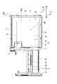
- FIG. 5 is a schematic cross-sectional view showing a cooking chamber 100A according to the present embodiment. Specifically, FIG. 5 shows a cross section of the cooking chamber 100A cut along a plane orthogonal to the left-right direction.
- the drawer type cooking cooker 100 further includes a first blower unit 14.
- the first blower unit 14 circulates the first air F1 between the inside of the cooking chamber 100A and the inside of the first blower chamber 14A.
- the first blower portion 14 has a first suction hole portion 14D, a first blowout hole portion 14C, and a first partition member 14B.
- the first suction hole portion 14D is located in the third direction D3 with respect to the accommodation space 120.
- the first outlet hole portion 14C is located in the third direction D3 with respect to the accommodation space 120. More specifically, the first blower portion 14 is located above the cooking chamber 100A via the top wall 1C.
- the first suction hole portion 14D is located above the cooking chamber 100A.
- the first outlet hole portion 14C is located above the cooking chamber 100A.
- the first blower portion 14 sucks the first air F1 in the cooking chamber 100A through the first suction hole portion 14D, and blows out the first air F1 into the cooking chamber 100A through the first blowing hole portion 14C. Specifically, the first blower unit 14 sucks in the first air F1 from the predetermined region EA in the accommodation space 120 and blows out the first air F1 to the predetermined region EA in the accommodation space 120.
- the predetermined area EA is, for example, a central area in the accommodation space 120. In the predetermined region EA, for example, the central portion of the object to be heated H is arranged.
- the first suction hole portion 14D and the first outlet hole portion 14C are located in the same third direction D3 with respect to the accommodation space 120, the first suction hole portion 14D and the first blowout hole portion 14C are located in the same third direction D3 with respect to the accommodation space 120.
- the distance between the hole portion 14D and the first blowout hole portion 14C is shortened.
- the circulation path of the first air F1 is also shortened. Therefore, the predetermined region EA in the cooking chamber 100A can be heated in a short time.
- first suction hole portion 14D and the first outlet hole portion 14C are located above the cooking chamber 100A.
- the distance between the top wall 1C and the bottom wall 1D is a short rectangular cuboid-shaped cooking chamber 100A and the predetermined area EA is the central area in the accommodation space 120, the first suction hole portion 14D and the predetermined area The distance between the EA and the distance between the first outlet hole portion 14C and the predetermined region EA are shortened. As a result, the predetermined area EA in the cooking chamber 100A can be heated in a shorter time by the first blower unit 14.
- the first blower unit 14 further includes a first blower chamber 14A, a first heater 141, a first centrifugal fan 142, a first drive unit 143, and a first energization unit 144.
- the first centrifugal fan 142 is an example of a “first fan”.
- the first blower chamber 14A is, for example, a box-shaped member.
- the first centrifugal fan 142 has a plurality of blades.
- the first heater 141 and the first centrifugal fan 142 are housed in the first blower chamber 14A.
- the first heater 141 is arranged above the cooking chamber 100A.
- the first heater 141 heats the first air F1 in the first ventilation chamber 14A.
- the shape of the first heater 141 is an annulus when viewed from the upper side to the lower side.
- the first heater 141 is arranged along the outer circumference of the first centrifugal fan 142.
- the first centrifugal fan 142 blows the first air F1 heated by the first heater 141 into the cooking chamber 100A. Therefore, the predetermined region EA in the cooking chamber 100A can be heated in a short time.
- the first drive unit 143 is located outside the first blower chamber 14A.
- the first drive unit 143 is connected to an external power source.
- the first drive unit 143 drives the first centrifugal fan 142.
- the first drive unit 143 includes, for example, a motor.
- the first drive unit 143 is controlled by the control unit 5.
- the first energizing unit 144 is located outside the first blower chamber 14A.
- the first energizing unit 144 is connected to an external power source.
- the first energizing unit 144 energizes the first heater 141.
- the energized first heater 141 generates heat.
- the first drive unit 143 is controlled by the control unit 5.
- the first energizing unit 144 includes, for example, a switch.
- FIG. 6 is a diagram showing a first partition member 14B according to the present embodiment.
- the first partition member 14B is located above the accommodation space 120. Specifically, the first partition member 14B is located between the first blower chamber 14A and the cooking chamber 100A.
- the first partition member 14B is, for example, a metal plate-shaped member.
- the shape of the first partition member 14B is, for example, a square when viewed from the upper side to the lower side.
- the first partition member 14B is arranged at a substantially central portion of the top wall 1C.
- the first suction hole portion 14D and the first outlet hole portion 14C are arranged in the first partition member 14B. Therefore, the first suction hole portion 14D and the first outlet hole portion 14C can be easily arranged above the accommodation space 120.
- the first suction hole portion 14D is, for example, an aggregate of a plurality of punch holes.
- the first outlet hole portion 14C is also, for example, an aggregate of a plurality of punch holes.
- Punch holes are an example of suction holes and blow holes.
- the punch holes are, for example, circular.
- the diameter of each punch hole of the first suction hole portion 14D and the first outlet hole portion 14C is, for example, 3.4 mm. Therefore, the sizes of the first suction hole portion 14D and the first outlet hole portion 14C are small. As a result, when cleaning the inside of the cooking chamber 100A, it is possible to prevent tools and the like from being caught in each of the first suction hole portion 14D and the first outlet hole portion 14C.
- the first outlet hole portion 14C surrounds the first suction hole portion 14D.
- the first suction hole portion 14D is located at the central portion of the first partition member 14B.
- the shape of the aggregate of the plurality of punched holes of the first suction hole portion 14D is, for example, circular.
- the first outlet hole portion 14C is formed along the outer circumference of the first suction hole portion 14D.
- the shape of the aggregate of the plurality of punched holes of the first blowout hole portion 14C is, for example, an annular shape.
- the first centrifugal fan 142 faces the cooking chamber 100A via the first partition member 14B.
- the first suction hole portion 14D faces the first centrifugal fan 142.
- the first driving unit 143 drives the first centrifugal fan 142, and the first energizing unit 144 energizes the first heater 141.
- the first centrifugal fan 142 sucks the first air F1 in the cooking chamber 100A into the first air blowing chamber 14A through the first suction hole portion 14D.
- the first air F1 sucked into the first ventilation chamber 14A is heated by the first heater 141.
- the first centrifugal fan 142 blows the first air F1 in the first blower chamber 14A into the cooking chamber 100A through the first blowout hole portion 14C.
- the first air F1 blown into the cooking chamber 100A moves downward. After that, the first air F1 that has reached the peripheral region of the predetermined region EA in the cooking chamber 100A moves toward, for example, the central region of the predetermined region EA, reverses the moving direction, and moves upward. .. That is, the predetermined region EA is arranged below the first heater 141 and the first centrifugal fan 142. The first air F1 moving upward moves in the cooking chamber 100A. After that, the first air F1 is sucked into the first air chamber 14A again from the first suction hole portion 14D. In this way, the first blower unit 14 circulates the first air F1 between the first blower chamber 14A and the predetermined region EA in the cooking chamber 100A.
- the predetermined region EA in the cooking chamber 100A can be heated more uniformly.
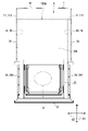
- FIG. 7 is a diagram showing a schematic cross section of the cooking chamber 100A according to the present embodiment. Specifically, FIG. 7 shows a cross section of the cooking chamber 100A cut along a plane orthogonal to the left-right direction.
- the drawer type cooking cooker 100 further includes a second blower unit 13.
- the second blower unit 13 circulates the second air F2 between the inside of the cooking chamber 100A and the inside of the second blower chamber 13A.
- the second blower portion 13 has a second suction hole portion 13D, a second blowout hole portion 13C, and a second partition member 13B.
- the second suction hole portion 13D is located in the direction opposite to the first direction D1 with respect to the accommodation space 120.
- the second outlet hole portion 13C is located in the direction opposite to the first direction D1 with respect to the accommodation space 120.
- the second blower portion 13 is located on the rear side of the cooking chamber 100A via the back wall 1E.
- the rear side of the cooking room 100A is an example of "a predetermined side of the cooking room 100A".
- the second suction hole portion 13D is located on the rear side of the cooking chamber 100A.
- the second outlet 13C is located on the rear side of the cooking chamber 100A.
- the second air blower 13 sucks the second air F2 in the cooking chamber 100A through the second suction hole 13D, and blows the second air F2 into the cooking chamber 100A through the second blowing hole 13C. Specifically, the second blower unit 13 sucks in the second air F2 from the central portion in the cooking chamber 100A and blows out the second air F2 to the peripheral portion in the cooking chamber 100A.
- the second blower unit 13 further includes a second blower chamber 13A, a second heater 131, a second centrifugal fan 132, a second drive unit 133, and a second energizing unit 134.
- the second centrifugal fan 132 is an example of a “second fan”.
- the second blower chamber 13A is, for example, a box-shaped member.
- the second centrifugal fan 132 has a plurality of blades.
- the second heater 131 and the second centrifugal fan 132 are housed in the second blower chamber 13A.
- the second heater 131 is arranged on the rear side of the cooking chamber 100A.
- the second heater 131 heats the second air F2 in the second ventilation chamber 13A.
- the shape of the second heater 131 is an annulus when viewed from the front side to the rear side.
- the second heater 131 is arranged along the outer circumference of the second centrifugal fan 132. As a result, the second centrifugal fan 132 blows the second air F2 heated by the second heater 131 into the cooking chamber 100A. Therefore, the entire cooking chamber 100A can be heated in a short time.
- the second drive unit 133 is located outside the second blower chamber 13A.
- the second drive unit 133 is connected to an external power source.
- the second drive unit 133 drives the second centrifugal fan 132.
- the second drive unit 133 includes, for example, a motor. Then, the second drive unit 133 is controlled by the control unit 5.
- the second energizing unit 134 is located outside the second blower chamber 13A.
- the second energizing unit 134 is connected to an external power source.
- the second energizing unit 134 energizes the second heater 131.
- the energized second heater 131 generates heat.
- the second energizing unit 134 is controlled by the control unit 5.
- the second energizing unit 134 includes, for example, a switch.
- the number of blades of the second centrifugal fan 132 is smaller than the number of blades of the first centrifugal fan 142.
- the size of the second centrifugal fan 132 is larger than the size of the first centrifugal fan 142.
- the size of the diameter of the second centrifugal fan 132 is larger than the size of the diameter of the first centrifugal fan 142.
- the thickness along the rotation axis of the second centrifugal fan 132 is larger than the thickness along the rotation axis of the first centrifugal fan 142. Therefore, the size of the second blower chamber 13A is larger than the size of the first blower chamber 14A.
- the thickness of the second blower chamber 13A along the rotation axis is larger than the thickness of the first blower chamber 14A along the rotation axis.
- the first blower unit 14 can heat the predetermined region EA in the cooking chamber 100A in a short time, and the second blower unit 13 can heat the entire cooking chamber 100A.
- FIG. 8 is a diagram showing a second partition member 13B according to the present embodiment.
- the second partition member 13B is located on the rear side of the accommodation space 120. Specifically, the second partition member 13B is located between the second blower chamber 13A and the cooking chamber 100A.
- the second partition member 13B is, for example, a metal plate-shaped member.
- the shape of the second partition member 13B is, for example, a rectangle when viewed from the front side to the rear side.
- the second partition member 13B is arranged on substantially the entire surface of the back wall 1E.
- the second suction hole portion 13D and the second outlet hole portion 13C are arranged in the second partition member 13B. Therefore, the second suction hole portion 13D and the second outlet hole portion 13C can be easily arranged behind the accommodation space 120.
- the second suction hole portion 13D is, for example, an aggregate of a plurality of punch holes.
- the second outlet hole portion 13C is also, for example, an aggregate of a plurality of punch holes.
- Punch holes are an example of suction holes and blow holes.
- the punch holes are, for example, circular.
- the diameter of each punch hole of the second suction hole portion 13D and the second outlet hole portion 13C is, for example, 3.4 mm. Therefore, the sizes of the second suction hole portion 13D and the second outlet hole portion 13C are small. As a result, when cleaning the inside of the cooking chamber 100A, it is possible to prevent tools and the like from being caught in each of the second suction hole portion 13D and the second outlet hole portion 13C.
- the second outlet hole portion 13C is arranged along the outer circumference of the second partition member 13B.
- the distance between the second blow-out hole portion 13C and the second suction hole portion 13D is longer than the distance between the first blow-out hole portion 14C and the first suction hole portion 14D.
- the second suction hole portion 13D is located at the central portion of the second partition member 13B.
- the shape of the aggregate of the plurality of punched holes of the second suction hole portion 13D is, for example, circular.
- the second outlet hole portion 13C is located at the peripheral edge portion along the edge of the back wall 1E.
- the second peripheral air outlet 13C includes a first peripheral air outlet 13C1A, a second peripheral air outlet 13C1B, a third peripheral air outlet 13C1C, and a fourth peripheral air outlet 13C1D. ..
- the first peripheral edge blowing hole portion 13C1A is located in the upper right region of the back wall 1E.
- the second peripheral blowout hole portion 13C1B is located in the lower right region of the back wall 1E.
- the third peripheral edge blowout hole portion 13C1C is located in the lower left region of the back wall 1E.
- the fourth peripheral blowout hole portion 13C1D is located in the upper left region of the back wall 1E.
- the distance between the outlet and the suction hole is, for example, the distance between the center of the suction hole and the outlet farthest from the center of the suction hole.
- the second centrifugal fan 132 faces the cooking chamber 100A via the second partition member 13B.
- the second suction hole portion 13D faces the second centrifugal fan 132.
- the second drive unit 133 drives the second centrifugal fan 132, and the second energization unit 134 energizes the second heater 131.
- the second centrifugal fan 132 sucks the second air F2 in the cooking chamber 100A into the second ventilation chamber 13A through the second suction hole portion 13D.
- the second air F2 sucked into the second ventilation chamber 13A is heated by the second heater 131.
- the second centrifugal fan 132 blows the second air F2 in the second blower chamber 13A into the cooking chamber 100A through the second blowout hole portion 13C.
- the second air F2 blown into the cooking chamber 100A moves forward mainly along the right wall 1A and the left wall 1B. After that, the second air F2 that has reached the rear surface of the lid portion 21 reverses the moving direction and moves toward the rear. The second air F2 that moves toward the rear moves in the cooking chamber 100A. After that, the second air F2 is sucked into the second air chamber 13A again from the second suction hole portion 13D. In this way, the second blower unit 13 circulates the second air F2 between the inside of the second blower chamber 13A and the inside of the cooking chamber 100A.
- the second blowing hole portion 13C is arranged along the outer circumference of the second partition member 13B, so that the second blowing portion 13 causes the inside of the cooking chamber 100A. The whole of can be heated more uniformly.
- the drawer-type cooking cooker 100 further includes a grill portion 16.
- the grill portion 16 has a cooking heater 161 and an energizing portion 162.
- the cooking heater 161 is an example of a “third heater”.
- the cooking heater 161 is located in the third direction D3 with respect to the accommodation space 120 and heats the object to be heated H.
- the cooking heater 161 is arranged in the upper part of the cooking chamber 100A.
- the heat to be heated can be cooked by conducting the heat generated by the heating heater 161 to the object to be heated H.
- the cooking heater 161 has a substantially U-shape when viewed from the upper side to the lower side. In this embodiment, three grill portions 16 are arranged.
- the cooking heater 161 is, for example, a sheathed heater.
- the energizing unit 162 is located outside the left wall 1B.
- the energizing unit 162 is connected to an external power source.
- the energizing unit 162 energizes the cooking heater 161.
- the energized cooking heater 161 generates heat.
- the energizing unit 162 is controlled by the control unit 5.
- the energizing unit 162 includes, for example, a switch.
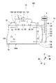
- FIG. 9 is a block diagram showing a configuration of a drawer type cooking cooker 100 according to the present embodiment.
- the control unit 5 further includes a thermistor 51.
- the thermistor 51 is an example of a “temperature detection unit”.
- the thermistor 51 detects the temperature inside the cooking chamber 100A.
- the thermistor 51 may be arranged in the cooking chamber 100A or in the first air blowing chamber 14A.
- the thermistor 51 is connected to the control unit 5.
- the thermistor 51 outputs the detection result to the control unit 5 at predetermined time intervals. Specifically, the control unit 5 calculates the temperature of the air in the predetermined region EA in the cooking chamber 100A based on the detection result of the thermistor 51.
- the control unit 5 executes the first drive unit 143, the second drive unit 133, the first energization unit 144, the second energization unit 134, the energization unit 162, and the drive motor. 41, the operation panel 3, and the storage unit 6 are controlled. Specifically, the control unit 5 controls the first drive unit 143, the second drive unit 133, the first energization unit 144, the second energization unit 134, and the energization unit 162 based on the detection result of the thermistor 51. do. As a result, the control unit 5 can control the first drive unit 143, the second drive unit 133, the first energization unit 144, the second energization unit 134, and the energization unit 162 at an appropriate timing.
- FIG. 10 is a diagram showing a schematic cross section of the cooking chamber 100A according to the present embodiment. Specifically, FIG. 10 shows a cross section of a cooking chamber 100A that performs a "cooking process".
- "cooking process” indicates that the object to be heated H is cooked in a state where the temperature in the cooking chamber 100A is substantially the same as the threshold temperature.
- the threshold temperature is set by the user or calculated by the control unit 5 based on the type of the object to be heated H, a table, or the like.
- the second drive unit 133 drives the second centrifugal fan 132.
- the second energizing unit 134 energizes the second heater 131 and stops the energization of the second heater 131.
- the energizing unit 162 energizes the cooking heater 161. As a result, the heat generated by the heating heater 161 is conducted to the object H to be heated, thereby cooking the object H to be heated.
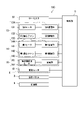
- FIG. 11 is a time chart executed by the control unit 5 according to the present embodiment.
- the horizontal axis represents time.
- the vertical axis indicates which of the ON state and the OFF state of the first drive unit 143, the second drive unit 133, the first energization unit 144, and the second energization unit 134, respectively. Indicates whether the state is.
- the ON state indicates an energized state or a driving state.
- the OFF state indicates a non-energized state or a non-driving state.
- FIG. 12 is a graph showing the relationship between the temperature and time of the predetermined region EA included in the cooking chamber 100A according to the present embodiment.
- the horizontal axis represents time
- the vertical axis represents temperature
- the temperature change of the predetermined region EA contained in the cooking chamber 100A is indicated by the solid line LA.
- the temperature is a temperature calculated based on the detection result of the thermistor 51.
- the temperature in the cooking chamber 100A exceeds the threshold temperature TT at least once before the object H to be heated is accommodated in the cooking chamber 100A.
- the "preheat treatment” indicates a process in which the temperature of the predetermined region EA in the cooking chamber 100A exceeds the threshold temperature TT before the object H to be heated is housed in the cooking chamber 100A.
- the temperature of the predetermined region EA in the cooking chamber 100A becomes substantially the same as the threshold temperature TT, and then the threshold temperature TT is reached from the time t1 to the first predetermined period.
- the first predetermined period ⁇ t1 indicates a period for the temperature of the first heater 141 to drop below the first predetermined temperature.
- the first predetermined temperature is an example of "predetermined temperature”.
- the first predetermined temperature indicates a temperature for suppressing overheating of the first blower chamber 14A.
- the first predetermined period ⁇ t1 and the first predetermined temperature are preset by the manufacturer or the like.
- the second heater 131 is energized at the time t1 when the temperature of the predetermined region EA in the cooking chamber 100A becomes substantially the same as the threshold temperature TT, and the time t1 to the first predetermined period ⁇ t1 The above has passed. As a result, the temperature of the second heater 131 rises.
- the user inputs to the operation panel 3 that the "preheat treatment” is to be executed.
- the control unit 5 accepts to execute the "preheat treatment”
- the first drive unit 143, the second drive unit 133, the first energization unit 144, and the second energization unit 134 are based on the detection result of the thermistor 51. And control.
- the control unit 5 drives the first drive unit 143 and energizes the first energization unit 144.
- the first blower unit 14 circulates the first air F1 between the first blower chamber 14A and the predetermined region EA in the cooking chamber 100A. As a result, the temperature of the predetermined region EA in the cooking chamber 100A rises.
- control unit 5 drives the first drive unit 143 and energizes the first energization unit 144, whether the temperature in the cooking chamber 100A is equal to or higher than the threshold temperature TT based on the detection result of the thermistor 51. Judge whether or not.
- the control unit 5 determines that the temperature of the predetermined region EA in the cooking chamber 100A is not equal to or higher than the threshold temperature TT, the control unit 5 drives the first drive unit 143 and continues to energize the first energization unit 144.
- the control unit 5 determines that the temperature of the predetermined region EA in the cooking chamber 100A is equal to or higher than the threshold temperature TT, the control unit 5 stops the driving of the first driving unit 143 and energizes the second energizing unit 134. .. As a result, the temperature of the predetermined region EA in the cooking chamber 100A exceeds the threshold temperature TT.
- the control unit 5 stops the energization of the first energizing unit 144 and stops the driving of the first driving unit 143 at t2 when the first predetermined period ⁇ t1 elapses from t1 when the second energizing unit 134 is energized. ..
- control unit 5 stops the energization of the first energizing unit 144, and drives the second driving unit 133 at t4 when the third predetermined period ⁇ t3 elapses from t1 when the second energizing unit 134 is energized. do.
- the third predetermined period ⁇ t3 is longer than the first predetermined period ⁇ t1.
- the third predetermined period ⁇ t3 indicates a period for the temperature of the second heater 131 to rise above the second predetermined temperature.
- the second predetermined temperature indicates a temperature for suppressing overheating of the second blower chamber 13A.
- the third predetermined period ⁇ t3 and the second predetermined temperature are preset by the manufacturer or the like. In other words, as shown in FIG. 7, the second blower unit 13 circulates the second air F2 between the inside of the second blower chamber 13A and the inside of the cooking chamber 100A. As a result, the overall temperature in the cooking chamber 100A becomes substantially the same as the threshold temperature TT.
- control unit 5 stops the energization of the first energizing unit 144, and notifies the end of the preheat treatment at t3 when the first predetermined period ⁇ t1 or more elapses from t2 when the second energizing unit 134 is energized. ..
- the control unit 5 stops the energization of the first heater 141 and energizes the second heater 131 before notifying the end of the preheat treatment.
- the control unit 5 notifies the end of the preheat treatment by voice or video.
- the cooking chamber 100A executes a "cooking process".
- the control unit 5 stops the energization of the first heater 141 and energizes the second heater 131 before notifying the end of the preheat treatment, so that the temperature of the second heater 131 has risen. Then, the heat-treated object H can be started to be cooked. As a result, the cooking period for cooking the object to be heated H can be shortened. For example, it is possible to start cooking the object to be heated H in a state where the overall temperature in the cooking chamber 100A has risen.
- control unit 5 stops the energization of the first energizing unit 144, and drives the first driving unit 143 at t2 when the first predetermined period ⁇ t1 elapses from t1 when the second energizing unit 134 is energized. Since it is stopped, the temperature of the first heater 141 drops below the first predetermined temperature. As a result, overheating of the first blower chamber 14A can be suppressed.
- the control unit 5 stops the energization of the first energizing unit 144 and notifies the end of the preheat treatment at t3 when the second predetermined period ⁇ t2 elapses from t1 when the second energizing unit 134 is energized. do.
- the second predetermined period ⁇ t2 indicates a period for the temperature in the cooking chamber 100A to drop to substantially the same temperature as the threshold temperature TT.
- the length of the second predetermined period ⁇ t2 is preferably not less than or equal to the length of the first predetermined period ⁇ t1 and not more than or equal to the length of the third predetermined period ⁇ t3.
- the second predetermined period ⁇ t2 is preset by the manufacturer or the like. As a result, it is possible to start cooking the object to be heated H in a state where the temperature in the cooking chamber 100A rises in a short time.
- control unit 5 drives the second drive unit 133 after notifying the end of the preheat treatment.
- the determination of the threshold temperature TT at the time of notification can be stabilized.
- overheating of the second heater 131 can be suppressed.
- the "heat insulation treatment” is further executed.
- the “heat retention treatment” indicates that after the “preheat treatment” is performed, the temperature in the cooking chamber 100A is maintained so as to be substantially the same as the threshold temperature TT.
- the control unit 5 controls the second energizing unit 134. More specifically, the control unit 5 energizes the second energizing unit 134 or stops the energization of the second energizing unit 134. As a result, the user does not have to house the object to be heated H in the cooking chamber 100A immediately after being notified of the end of the preheat treatment.
- the drawer type heating cooker 100 if the lid portion 21 is pulled out while the "cooking process”, the "preheat treatment”, and the “heat retention process” are being executed, the first energizing unit 144 And the energization of the second energizing unit 134 is stopped. As a result, it is possible to suppress the outflow of hot air toward the user who has opened the inside of the cooking chamber 100A.
- FIG. 13 is a flow chart for explaining a cooking method by the drawer type cooking cooker 100.
- step S101 the control unit 5 drives the first centrifugal fan 142 and energizes the first heater 141.
- step S102 the control unit 5 determines whether or not the temperature in the cooking chamber 100A is equal to or higher than the threshold temperature TT.
- the control unit 5 determines in step S102 that the temperature in the cooking chamber 100A is not equal to or higher than the threshold temperature TT, the process returns to step S102.
- step S102 determines in step S102 that the temperature in the cooking chamber 100A is equal to or higher than the threshold temperature TT.
- step S103 the control unit 5 stops energization of the first heater 141 and energizes the second heater 131.
- step S104 the control unit 5 stops driving the first centrifugal fan 142.
- step S105 the control unit 5 notifies the end of the preheat treatment.
- step S106 the control unit 5 drives the second centrifugal fan 132.
- step S107 the control unit 5 determines whether or not the object to be heated H is housed in the cooking chamber 100A. If the control unit 5 determines in step S107 that the object H to be heated is not housed in the cooking chamber 100A, the process proceeds to step S108. On the other hand, when the control unit 5 determines in step S107 that the object H to be heated is housed in the cooking chamber 100A, the process proceeds to step S109.
- step S108 the control unit 5 repeats energizing the second heater 131 and stopping the energization of the second heater 131. The process returns to step S106.
- step S109 the control unit 5 executes the "cooking process”. Then, the cooking method is completed.
- the cooking process is executed after the preheat treatment is executed, the cooking period for cooking the object H to be heated can be shortened.
- FIG. 14 is a diagram showing the appearance of a cabinet 200 to which the drawer-type cooking cooker 100 according to the present embodiment is mounted.
- the drawer type cooking cooker 100 is installed and installed in the cabinet 200.
- the cabinet 200 has an upper wall 200A, a lower wall 200B, a right wall 200C, a left wall 200D, and a rear wall 200E.
- the upper wall 200A, the lower wall 200B, the right wall 200C, the left wall 200D and the rear wall 200E form an accommodating portion 200F.
- the accommodating portion 200F is a rectangular cuboid space in which the drawer-type cooking cooker 100 is fitted.
- the drawer type cooking cooker 100 includes a first blower portion 14, a second blower portion 13, and a grill portion 16, and the present invention includes the first blower portion 14, the second blower portion 13, and the grill portion 16.
- the drawer type cooking cooker 100 may further include a microwave supply unit.
- control unit 5 notifies the end of the preheat treatment at t3 when the second predetermined period ⁇ t2 elapses from the time t1, but this is the present invention. Not limited to.
- the control unit 5 may notify the end of the preheat treatment based on the detection result of the thermistor 51.
- the present invention provides a cooking cooker and has industrial applicability.
- Control unit 131 2nd heater 132 2nd centrifugal fan 141 1st heater 142 1st centrifugal fan 100 Drawer type cooking cooker 100A Cooking room EA Predetermined area F1 1st air F2 2nd air TT Threshold temperature
Landscapes
- Engineering & Computer Science (AREA)
- Chemical & Material Sciences (AREA)
- Combustion & Propulsion (AREA)
- Mechanical Engineering (AREA)
- General Engineering & Computer Science (AREA)
- Electric Stoves And Ranges (AREA)
- Baking, Grill, Roasting (AREA)
Abstract
Description
131 第2ヒータ
132 第2遠心ファン
141 第1ヒータ
142 第1遠心ファン
100 引出し式加熱調理器
100A 加熱調理室
EA 所定領域
F1 第1空気
F2 第2空気
TT 閾値温度
Claims (9)
- 被加熱物を収容する加熱調理室と、
第1空気を加熱する第1ヒータと、
前記第1ヒータで加熱された前記第1空気を前記加熱調理室内に送風する第1ファンと、
第2空気を加熱する第2ヒータと、
前記第2ヒータで加熱された前記第2空気を前記加熱調理室内に送風する第2ファンと、
前記第1ヒータ、前記第1ファン、前記第2ヒータ及び前記第2ファンを制御する制御部と
を備え、
前記制御部は、予熱処理の終了を報知する前に、前記第1ヒータの通電を停止するとともに、前記第2ヒータに通電し、
前記予熱処理は、前記加熱調理室内に前記被加熱物が収容される前に、前記加熱調理室内の温度が少なくとも一度、閾値温度を超える処理を示す、加熱調理器。 - 前記制御部は、前記第1ヒータの通電を停止するとともに、前記第2ヒータに通電した時から第1所定期間が経過した時に、前記第1ファンの駆動を停止し、
前記第1所定期間は、前記第1ヒータの温度が所定温度以下に低下するための期間を示す、請求項1に記載の加熱調理器。 - 前記制御部は、前記第1ヒータの通電を停止するとともに、前記第2ヒータに通電した時から第2所定期間が経過した時に、前記予熱処理の終了を報知し、
前記第2所定期間は、前記加熱調理室内の温度が前記閾値温度と略同じ温度まで低下するための期間を示す、請求項1又は請求項2に記載の加熱調理器。 - 前記制御部は、前記予熱処理の終了を報知した後に、前記第2ファンを駆動する、請求項1から請求項3のいずれか1項に記載の加熱調理器。
- 前記第1ヒータは、前記加熱調理室の上方に配置され、
前記第2ヒータは、前記加熱調理室の所定側に配置され、
前記加熱調理室の上方と前記加熱調理室の所定側とは異なる、請求項1から請求項4のいずれか1項に記載の加熱調理器。 - 前記予熱処理は、前記加熱調理室内に含まれる所定領域の温度が少なくとも一度、前記閾値温度を超える処理を示し、
前記所定領域は、前記第1ヒータ及び前記第1ファンの下方に配置される、請求項1から請求項5のいずれか1項に記載の加熱調理器。 - 前記加熱調理室内の温度を検知する温度検知部を更に備え、
前記制御部は、前記温度検知部の検知結果に基づいて、前記第1ヒータ、前記第1ファン、前記第2ヒータ及び前記第2ファンを制御する、請求項1から請求項6のいずれか1項に記載の加熱調理器。 - 前記加熱調理室内に配置された第3ヒータを更に備え、
前記制御部は、前記温度検知部の検知結果に基づいて、前記第3ヒータを制御する、請求項7に記載の加熱調理器。 - 前記被加熱物を載置し、前記加熱調理室に対して引出可能な引出体を更に備え、
前記制御部は、前記引出体が引出された場合には、前記第1ヒータの通電及び前記第2ヒータの通電を停止する、請求項1から請求項8のいずれか1項に記載の加熱調理器。
Priority Applications (4)
| Application Number | Priority Date | Filing Date | Title |
|---|---|---|---|
| CA3204757A CA3204757A1 (en) | 2021-01-18 | 2022-01-17 | Heating cooking apparatus |
| US18/272,125 US20240142114A1 (en) | 2021-01-18 | 2022-01-17 | Heating cooking apparatus |
| JP2022575663A JPWO2022154117A1 (ja) | 2021-01-18 | 2022-01-17 | |
| EP22739522.5A EP4279816A4 (en) | 2021-01-18 | 2022-01-17 | STOVE |
Applications Claiming Priority (2)
| Application Number | Priority Date | Filing Date | Title |
|---|---|---|---|
| JP2021-005933 | 2021-01-18 | ||
| JP2021005933 | 2021-01-18 |
Publications (1)
| Publication Number | Publication Date |
|---|---|
| WO2022154117A1 true WO2022154117A1 (ja) | 2022-07-21 |
Family
ID=82448198
Family Applications (1)
| Application Number | Title | Priority Date | Filing Date |
|---|---|---|---|
| PCT/JP2022/001366 WO2022154117A1 (ja) | 2021-01-18 | 2022-01-17 | 加熱調理器 |
Country Status (5)
| Country | Link |
|---|---|
| US (1) | US20240142114A1 (ja) |
| EP (1) | EP4279816A4 (ja) |
| JP (1) | JPWO2022154117A1 (ja) |
| CA (1) | CA3204757A1 (ja) |
| WO (1) | WO2022154117A1 (ja) |
Citations (2)
| Publication number | Priority date | Publication date | Assignee | Title |
|---|---|---|---|---|
| JPH05172343A (ja) * | 1991-12-25 | 1993-07-09 | Mitsubishi Electric Corp | 加熱調理器 |
| JP2020118401A (ja) * | 2019-01-25 | 2020-08-06 | 株式会社ハーマン | 加熱調理器 |
Family Cites Families (2)
| Publication number | Priority date | Publication date | Assignee | Title |
|---|---|---|---|---|
| US8242413B2 (en) * | 2006-11-29 | 2012-08-14 | Lg Electronics Inc. | Method of controlling oven |
| JP6692972B1 (ja) * | 2019-07-31 | 2020-05-13 | シャープ株式会社 | 加熱調理器 |
-
2022
- 2022-01-17 JP JP2022575663A patent/JPWO2022154117A1/ja active Pending
- 2022-01-17 WO PCT/JP2022/001366 patent/WO2022154117A1/ja active Application Filing
- 2022-01-17 EP EP22739522.5A patent/EP4279816A4/en active Pending
- 2022-01-17 CA CA3204757A patent/CA3204757A1/en active Pending
- 2022-01-17 US US18/272,125 patent/US20240142114A1/en active Pending
Patent Citations (2)
| Publication number | Priority date | Publication date | Assignee | Title |
|---|---|---|---|---|
| JPH05172343A (ja) * | 1991-12-25 | 1993-07-09 | Mitsubishi Electric Corp | 加熱調理器 |
| JP2020118401A (ja) * | 2019-01-25 | 2020-08-06 | 株式会社ハーマン | 加熱調理器 |
Non-Patent Citations (1)
| Title |
|---|
| See also references of EP4279816A4 * |
Also Published As
| Publication number | Publication date |
|---|---|
| CA3204757A1 (en) | 2022-07-21 |
| US20240142114A1 (en) | 2024-05-02 |
| JPWO2022154117A1 (ja) | 2022-07-21 |
| EP4279816A4 (en) | 2024-05-22 |
| EP4279816A1 (en) | 2023-11-22 |
Similar Documents
| Publication | Publication Date | Title |
|---|---|---|
| CN105829803B (zh) | 加热烹调器 | |
| WO2021019825A1 (ja) | 加熱調理器 | |
| WO2022154117A1 (ja) | 加熱調理器 | |
| US20230067149A1 (en) | Heating cooking apparatus | |
| WO2021020390A1 (ja) | 加熱調理器 | |
| JP2021124267A (ja) | 加熱調理器 | |
| EP4006419A1 (en) | Heating cooker | |
| WO2022149588A1 (ja) | 加熱調理器 | |
| WO2021033687A1 (ja) | 引出し式加熱調理器 | |
| WO2021020389A1 (ja) | 加熱調理器 | |
| WO2021157559A1 (ja) | 加熱調理器 | |
| WO2022124299A1 (ja) | 加熱調理器 | |
| WO2021020345A1 (ja) | 加熱調理器 | |
| WO2022113998A1 (ja) | 加熱調理器 | |
| WO2021020343A1 (ja) | 加熱調理器 | |
| JP2009287832A (ja) | 加熱調理器 |
Legal Events
| Date | Code | Title | Description |
|---|---|---|---|
| 121 | Ep: the epo has been informed by wipo that ep was designated in this application |
Ref document number: 22739522 Country of ref document: EP Kind code of ref document: A1 |
|
| ENP | Entry into the national phase |
Ref document number: 2022575663 Country of ref document: JP Kind code of ref document: A |
|
| ENP | Entry into the national phase |
Ref document number: 3204757 Country of ref document: CA |
|
| WWE | Wipo information: entry into national phase |
Ref document number: 18272125 Country of ref document: US |
|
| NENP | Non-entry into the national phase |
Ref country code: DE |
|
| ENP | Entry into the national phase |
Ref document number: 2022739522 Country of ref document: EP Effective date: 20230818 |