WO2021010197A1 - 保護カバー部材及びこれを備える部材供給用シート - Google Patents
保護カバー部材及びこれを備える部材供給用シート Download PDFInfo
- Publication number
- WO2021010197A1 WO2021010197A1 PCT/JP2020/026307 JP2020026307W WO2021010197A1 WO 2021010197 A1 WO2021010197 A1 WO 2021010197A1 JP 2020026307 W JP2020026307 W JP 2020026307W WO 2021010197 A1 WO2021010197 A1 WO 2021010197A1
- Authority
- WO
- WIPO (PCT)
- Prior art keywords
- cover member
- protective cover
- film
- adhesive layer
- protective
- Prior art date
Links
Images


Classifications
-
- B—PERFORMING OPERATIONS; TRANSPORTING
- B81—MICROSTRUCTURAL TECHNOLOGY
- B81C—PROCESSES OR APPARATUS SPECIALLY ADAPTED FOR THE MANUFACTURE OR TREATMENT OF MICROSTRUCTURAL DEVICES OR SYSTEMS
- B81C1/00—Manufacture or treatment of devices or systems in or on a substrate
- B81C1/00777—Preserve existing structures from alteration, e.g. temporary protection during manufacturing
- B81C1/00825—Protect against mechanical threats, e.g. against shocks, or residues
-
- B—PERFORMING OPERATIONS; TRANSPORTING
- B32—LAYERED PRODUCTS
- B32B—LAYERED PRODUCTS, i.e. PRODUCTS BUILT-UP OF STRATA OF FLAT OR NON-FLAT, e.g. CELLULAR OR HONEYCOMB, FORM
- B32B27/00—Layered products comprising a layer of synthetic resin
-
- B—PERFORMING OPERATIONS; TRANSPORTING
- B32—LAYERED PRODUCTS
- B32B—LAYERED PRODUCTS, i.e. PRODUCTS BUILT-UP OF STRATA OF FLAT OR NON-FLAT, e.g. CELLULAR OR HONEYCOMB, FORM
- B32B27/00—Layered products comprising a layer of synthetic resin
- B32B27/06—Layered products comprising a layer of synthetic resin as the main or only constituent of a layer, which is next to another layer of the same or of a different material
- B32B27/08—Layered products comprising a layer of synthetic resin as the main or only constituent of a layer, which is next to another layer of the same or of a different material of synthetic resin
-
- B—PERFORMING OPERATIONS; TRANSPORTING
- B32—LAYERED PRODUCTS
- B32B—LAYERED PRODUCTS, i.e. PRODUCTS BUILT-UP OF STRATA OF FLAT OR NON-FLAT, e.g. CELLULAR OR HONEYCOMB, FORM
- B32B15/00—Layered products comprising a layer of metal
- B32B15/18—Layered products comprising a layer of metal comprising iron or steel
-
- B—PERFORMING OPERATIONS; TRANSPORTING
- B32—LAYERED PRODUCTS
- B32B—LAYERED PRODUCTS, i.e. PRODUCTS BUILT-UP OF STRATA OF FLAT OR NON-FLAT, e.g. CELLULAR OR HONEYCOMB, FORM
- B32B15/00—Layered products comprising a layer of metal
- B32B15/20—Layered products comprising a layer of metal comprising aluminium or copper
-
- B—PERFORMING OPERATIONS; TRANSPORTING
- B32—LAYERED PRODUCTS
- B32B—LAYERED PRODUCTS, i.e. PRODUCTS BUILT-UP OF STRATA OF FLAT OR NON-FLAT, e.g. CELLULAR OR HONEYCOMB, FORM
- B32B25/00—Layered products comprising a layer of natural or synthetic rubber
- B32B25/20—Layered products comprising a layer of natural or synthetic rubber comprising silicone rubber
-
- B—PERFORMING OPERATIONS; TRANSPORTING
- B32—LAYERED PRODUCTS
- B32B—LAYERED PRODUCTS, i.e. PRODUCTS BUILT-UP OF STRATA OF FLAT OR NON-FLAT, e.g. CELLULAR OR HONEYCOMB, FORM
- B32B27/00—Layered products comprising a layer of synthetic resin
- B32B27/28—Layered products comprising a layer of synthetic resin comprising synthetic resins not wholly covered by any one of the sub-groups B32B27/30 - B32B27/42
- B32B27/281—Layered products comprising a layer of synthetic resin comprising synthetic resins not wholly covered by any one of the sub-groups B32B27/30 - B32B27/42 comprising polyimides
-
- B—PERFORMING OPERATIONS; TRANSPORTING
- B32—LAYERED PRODUCTS
- B32B—LAYERED PRODUCTS, i.e. PRODUCTS BUILT-UP OF STRATA OF FLAT OR NON-FLAT, e.g. CELLULAR OR HONEYCOMB, FORM
- B32B27/00—Layered products comprising a layer of synthetic resin
- B32B27/28—Layered products comprising a layer of synthetic resin comprising synthetic resins not wholly covered by any one of the sub-groups B32B27/30 - B32B27/42
- B32B27/286—Layered products comprising a layer of synthetic resin comprising synthetic resins not wholly covered by any one of the sub-groups B32B27/30 - B32B27/42 comprising polysulphones; polysulfides
-
- B—PERFORMING OPERATIONS; TRANSPORTING
- B32—LAYERED PRODUCTS
- B32B—LAYERED PRODUCTS, i.e. PRODUCTS BUILT-UP OF STRATA OF FLAT OR NON-FLAT, e.g. CELLULAR OR HONEYCOMB, FORM
- B32B27/00—Layered products comprising a layer of synthetic resin
- B32B27/28—Layered products comprising a layer of synthetic resin comprising synthetic resins not wholly covered by any one of the sub-groups B32B27/30 - B32B27/42
- B32B27/288—Layered products comprising a layer of synthetic resin comprising synthetic resins not wholly covered by any one of the sub-groups B32B27/30 - B32B27/42 comprising polyketones
-
- B—PERFORMING OPERATIONS; TRANSPORTING
- B32—LAYERED PRODUCTS
- B32B—LAYERED PRODUCTS, i.e. PRODUCTS BUILT-UP OF STRATA OF FLAT OR NON-FLAT, e.g. CELLULAR OR HONEYCOMB, FORM
- B32B27/00—Layered products comprising a layer of synthetic resin
- B32B27/30—Layered products comprising a layer of synthetic resin comprising vinyl (co)polymers; comprising acrylic (co)polymers
- B32B27/304—Layered products comprising a layer of synthetic resin comprising vinyl (co)polymers; comprising acrylic (co)polymers comprising vinyl halide (co)polymers, e.g. PVC, PVDC, PVF, PVDF
-
- B—PERFORMING OPERATIONS; TRANSPORTING
- B32—LAYERED PRODUCTS
- B32B—LAYERED PRODUCTS, i.e. PRODUCTS BUILT-UP OF STRATA OF FLAT OR NON-FLAT, e.g. CELLULAR OR HONEYCOMB, FORM
- B32B27/00—Layered products comprising a layer of synthetic resin
- B32B27/32—Layered products comprising a layer of synthetic resin comprising polyolefins
- B32B27/322—Layered products comprising a layer of synthetic resin comprising polyolefins comprising halogenated polyolefins, e.g. PTFE
-
- B—PERFORMING OPERATIONS; TRANSPORTING
- B32—LAYERED PRODUCTS
- B32B—LAYERED PRODUCTS, i.e. PRODUCTS BUILT-UP OF STRATA OF FLAT OR NON-FLAT, e.g. CELLULAR OR HONEYCOMB, FORM
- B32B27/00—Layered products comprising a layer of synthetic resin
- B32B27/36—Layered products comprising a layer of synthetic resin comprising polyesters
- B32B27/365—Layered products comprising a layer of synthetic resin comprising polyesters comprising polycarbonates
-
- B—PERFORMING OPERATIONS; TRANSPORTING
- B32—LAYERED PRODUCTS
- B32B—LAYERED PRODUCTS, i.e. PRODUCTS BUILT-UP OF STRATA OF FLAT OR NON-FLAT, e.g. CELLULAR OR HONEYCOMB, FORM
- B32B3/00—Layered products comprising a layer with external or internal discontinuities or unevennesses, or a layer of non-planar form; Layered products having particular features of form
- B32B3/02—Layered products comprising a layer with external or internal discontinuities or unevennesses, or a layer of non-planar form; Layered products having particular features of form characterised by features of form at particular places, e.g. in edge regions
- B32B3/04—Layered products comprising a layer with external or internal discontinuities or unevennesses, or a layer of non-planar form; Layered products having particular features of form characterised by features of form at particular places, e.g. in edge regions characterised by at least one layer folded at the edge, e.g. over another layer ; characterised by at least one layer enveloping or enclosing a material
-
- B—PERFORMING OPERATIONS; TRANSPORTING
- B32—LAYERED PRODUCTS
- B32B—LAYERED PRODUCTS, i.e. PRODUCTS BUILT-UP OF STRATA OF FLAT OR NON-FLAT, e.g. CELLULAR OR HONEYCOMB, FORM
- B32B3/00—Layered products comprising a layer with external or internal discontinuities or unevennesses, or a layer of non-planar form; Layered products having particular features of form
- B32B3/26—Layered products comprising a layer with external or internal discontinuities or unevennesses, or a layer of non-planar form; Layered products having particular features of form characterised by a particular shape of the outline of the cross-section of a continuous layer; characterised by a layer with cavities or internal voids ; characterised by an apertured layer
- B32B3/30—Layered products comprising a layer with external or internal discontinuities or unevennesses, or a layer of non-planar form; Layered products having particular features of form characterised by a particular shape of the outline of the cross-section of a continuous layer; characterised by a layer with cavities or internal voids ; characterised by an apertured layer characterised by a layer formed with recesses or projections, e.g. hollows, grooves, protuberances, ribs
-
- B—PERFORMING OPERATIONS; TRANSPORTING
- B32—LAYERED PRODUCTS
- B32B—LAYERED PRODUCTS, i.e. PRODUCTS BUILT-UP OF STRATA OF FLAT OR NON-FLAT, e.g. CELLULAR OR HONEYCOMB, FORM
- B32B5/00—Layered products characterised by the non- homogeneity or physical structure, i.e. comprising a fibrous, filamentary, particulate or foam layer; Layered products characterised by having a layer differing constitutionally or physically in different parts
- B32B5/02—Layered products characterised by the non- homogeneity or physical structure, i.e. comprising a fibrous, filamentary, particulate or foam layer; Layered products characterised by having a layer differing constitutionally or physically in different parts characterised by structural features of a fibrous or filamentary layer
- B32B5/022—Non-woven fabric
-
- B—PERFORMING OPERATIONS; TRANSPORTING
- B32—LAYERED PRODUCTS
- B32B—LAYERED PRODUCTS, i.e. PRODUCTS BUILT-UP OF STRATA OF FLAT OR NON-FLAT, e.g. CELLULAR OR HONEYCOMB, FORM
- B32B5/00—Layered products characterised by the non- homogeneity or physical structure, i.e. comprising a fibrous, filamentary, particulate or foam layer; Layered products characterised by having a layer differing constitutionally or physically in different parts
- B32B5/02—Layered products characterised by the non- homogeneity or physical structure, i.e. comprising a fibrous, filamentary, particulate or foam layer; Layered products characterised by having a layer differing constitutionally or physically in different parts characterised by structural features of a fibrous or filamentary layer
- B32B5/024—Woven fabric
-
- B—PERFORMING OPERATIONS; TRANSPORTING
- B32—LAYERED PRODUCTS
- B32B—LAYERED PRODUCTS, i.e. PRODUCTS BUILT-UP OF STRATA OF FLAT OR NON-FLAT, e.g. CELLULAR OR HONEYCOMB, FORM
- B32B5/00—Layered products characterised by the non- homogeneity or physical structure, i.e. comprising a fibrous, filamentary, particulate or foam layer; Layered products characterised by having a layer differing constitutionally or physically in different parts
- B32B5/18—Layered products characterised by the non- homogeneity or physical structure, i.e. comprising a fibrous, filamentary, particulate or foam layer; Layered products characterised by having a layer differing constitutionally or physically in different parts characterised by features of a layer of foamed material
-
- B—PERFORMING OPERATIONS; TRANSPORTING
- B32—LAYERED PRODUCTS
- B32B—LAYERED PRODUCTS, i.e. PRODUCTS BUILT-UP OF STRATA OF FLAT OR NON-FLAT, e.g. CELLULAR OR HONEYCOMB, FORM
- B32B7/00—Layered products characterised by the relation between layers; Layered products characterised by the relative orientation of features between layers, or by the relative values of a measurable parameter between layers, i.e. products comprising layers having different physical, chemical or physicochemical properties; Layered products characterised by the interconnection of layers
- B32B7/04—Interconnection of layers
- B32B7/12—Interconnection of layers using interposed adhesives or interposed materials with bonding properties
-
- B—PERFORMING OPERATIONS; TRANSPORTING
- B65—CONVEYING; PACKING; STORING; HANDLING THIN OR FILAMENTARY MATERIAL
- B65D—CONTAINERS FOR STORAGE OR TRANSPORT OF ARTICLES OR MATERIALS, e.g. BAGS, BARRELS, BOTTLES, BOXES, CANS, CARTONS, CRATES, DRUMS, JARS, TANKS, HOPPERS, FORWARDING CONTAINERS; ACCESSORIES, CLOSURES, OR FITTINGS THEREFOR; PACKAGING ELEMENTS; PACKAGES
- B65D43/00—Lids or covers for rigid or semi-rigid containers
-
- C—CHEMISTRY; METALLURGY
- C09—DYES; PAINTS; POLISHES; NATURAL RESINS; ADHESIVES; COMPOSITIONS NOT OTHERWISE PROVIDED FOR; APPLICATIONS OF MATERIALS NOT OTHERWISE PROVIDED FOR
- C09J—ADHESIVES; NON-MECHANICAL ASPECTS OF ADHESIVE PROCESSES IN GENERAL; ADHESIVE PROCESSES NOT PROVIDED FOR ELSEWHERE; USE OF MATERIALS AS ADHESIVES
- C09J7/00—Adhesives in the form of films or foils
- C09J7/20—Adhesives in the form of films or foils characterised by their carriers
-
- C—CHEMISTRY; METALLURGY
- C09—DYES; PAINTS; POLISHES; NATURAL RESINS; ADHESIVES; COMPOSITIONS NOT OTHERWISE PROVIDED FOR; APPLICATIONS OF MATERIALS NOT OTHERWISE PROVIDED FOR
- C09J—ADHESIVES; NON-MECHANICAL ASPECTS OF ADHESIVE PROCESSES IN GENERAL; ADHESIVE PROCESSES NOT PROVIDED FOR ELSEWHERE; USE OF MATERIALS AS ADHESIVES
- C09J7/00—Adhesives in the form of films or foils
- C09J7/40—Adhesives in the form of films or foils characterised by release liners
-
- G—PHYSICS
- G09—EDUCATION; CRYPTOGRAPHY; DISPLAY; ADVERTISING; SEALS
- G09F—DISPLAYING; ADVERTISING; SIGNS; LABELS OR NAME-PLATES; SEALS
- G09F9/00—Indicating arrangements for variable information in which the information is built-up on a support by selection or combination of individual elements
-
- H—ELECTRICITY
- H04—ELECTRIC COMMUNICATION TECHNIQUE
- H04R—LOUDSPEAKERS, MICROPHONES, GRAMOPHONE PICK-UPS OR LIKE ACOUSTIC ELECTROMECHANICAL TRANSDUCERS; DEAF-AID SETS; PUBLIC ADDRESS SYSTEMS
- H04R19/00—Electrostatic transducers
- H04R19/005—Electrostatic transducers using semiconductor materials
-
- H—ELECTRICITY
- H05—ELECTRIC TECHNIQUES NOT OTHERWISE PROVIDED FOR
- H05K—PRINTED CIRCUITS; CASINGS OR CONSTRUCTIONAL DETAILS OF ELECTRIC APPARATUS; MANUFACTURE OF ASSEMBLAGES OF ELECTRICAL COMPONENTS
- H05K3/00—Apparatus or processes for manufacturing printed circuits
- H05K3/30—Assembling printed circuits with electric components, e.g. with resistor
- H05K3/32—Assembling printed circuits with electric components, e.g. with resistor electrically connecting electric components or wires to printed circuits
- H05K3/34—Assembling printed circuits with electric components, e.g. with resistor electrically connecting electric components or wires to printed circuits by soldering
-
- B—PERFORMING OPERATIONS; TRANSPORTING
- B32—LAYERED PRODUCTS
- B32B—LAYERED PRODUCTS, i.e. PRODUCTS BUILT-UP OF STRATA OF FLAT OR NON-FLAT, e.g. CELLULAR OR HONEYCOMB, FORM
- B32B2266/00—Composition of foam
- B32B2266/02—Organic
- B32B2266/0214—Materials belonging to B32B27/00
-
- B—PERFORMING OPERATIONS; TRANSPORTING
- B32—LAYERED PRODUCTS
- B32B—LAYERED PRODUCTS, i.e. PRODUCTS BUILT-UP OF STRATA OF FLAT OR NON-FLAT, e.g. CELLULAR OR HONEYCOMB, FORM
- B32B2266/00—Composition of foam
- B32B2266/04—Inorganic
- B32B2266/045—Metal
-
- B—PERFORMING OPERATIONS; TRANSPORTING
- B32—LAYERED PRODUCTS
- B32B—LAYERED PRODUCTS, i.e. PRODUCTS BUILT-UP OF STRATA OF FLAT OR NON-FLAT, e.g. CELLULAR OR HONEYCOMB, FORM
- B32B2305/00—Condition, form or state of the layers or laminate
- B32B2305/02—Cellular or porous
- B32B2305/026—Porous
-
- B—PERFORMING OPERATIONS; TRANSPORTING
- B32—LAYERED PRODUCTS
- B32B—LAYERED PRODUCTS, i.e. PRODUCTS BUILT-UP OF STRATA OF FLAT OR NON-FLAT, e.g. CELLULAR OR HONEYCOMB, FORM
- B32B2307/00—Properties of the layers or laminate
- B32B2307/30—Properties of the layers or laminate having particular thermal properties
- B32B2307/306—Resistant to heat
-
- B—PERFORMING OPERATIONS; TRANSPORTING
- B32—LAYERED PRODUCTS
- B32B—LAYERED PRODUCTS, i.e. PRODUCTS BUILT-UP OF STRATA OF FLAT OR NON-FLAT, e.g. CELLULAR OR HONEYCOMB, FORM
- B32B2307/00—Properties of the layers or laminate
- B32B2307/50—Properties of the layers or laminate having particular mechanical properties
- B32B2307/584—Scratch resistance
-
- B—PERFORMING OPERATIONS; TRANSPORTING
- B32—LAYERED PRODUCTS
- B32B—LAYERED PRODUCTS, i.e. PRODUCTS BUILT-UP OF STRATA OF FLAT OR NON-FLAT, e.g. CELLULAR OR HONEYCOMB, FORM
- B32B2307/00—Properties of the layers or laminate
- B32B2307/70—Other properties
- B32B2307/724—Permeability to gases, adsorption
-
- B—PERFORMING OPERATIONS; TRANSPORTING
- B32—LAYERED PRODUCTS
- B32B—LAYERED PRODUCTS, i.e. PRODUCTS BUILT-UP OF STRATA OF FLAT OR NON-FLAT, e.g. CELLULAR OR HONEYCOMB, FORM
- B32B2435/00—Closures, end caps, stoppers
-
- B—PERFORMING OPERATIONS; TRANSPORTING
- B81—MICROSTRUCTURAL TECHNOLOGY
- B81B—MICROSTRUCTURAL DEVICES OR SYSTEMS, e.g. MICROMECHANICAL DEVICES
- B81B7/00—Microstructural systems; Auxiliary parts of microstructural devices or systems
- B81B7/0032—Packages or encapsulation
- B81B7/0035—Packages or encapsulation for maintaining a controlled atmosphere inside of the chamber containing the MEMS
- B81B7/0038—Packages or encapsulation for maintaining a controlled atmosphere inside of the chamber containing the MEMS using materials for controlling the level of pressure, contaminants or moisture inside of the package, e.g. getters
-
- H—ELECTRICITY
- H04—ELECTRIC COMMUNICATION TECHNIQUE
- H04R—LOUDSPEAKERS, MICROPHONES, GRAMOPHONE PICK-UPS OR LIKE ACOUSTIC ELECTROMECHANICAL TRANSDUCERS; DEAF-AID SETS; PUBLIC ADDRESS SYSTEMS
- H04R2201/00—Details of transducers, loudspeakers or microphones covered by H04R1/00 but not provided for in any of its subgroups
- H04R2201/003—Mems transducers or their use
Definitions
- the present invention relates to a protective cover member arranged on the surface of an object having a surface having an opening to prevent foreign matter from entering the opening, and a member supply sheet for supplying the member.
- Patent Document 1 contains a porous membrane containing polytetrafluoroethylene (hereinafter referred to as "PTFE") as a main component, allowing sound to pass through, and blocking foreign substances such as water droplets from passing through.
- PTFE polytetrafluoroethylene
- a member comprising a heat resistant double-sided pressure-sensitive adhesive sheet arranged in a restricted area on at least one main surface of the porous membrane to secure the quality membrane to another component.
- the object of the present disclosure is to provide a protective cover member that can be removed while suppressing damage to an object.
- a protective cover member that is arranged on the surface of an object having a surface having an opening to prevent foreign matter from entering the opening.
- a protective film having a shape that covers the opening when the protective cover member is arranged on the surface,
- the base film bonded to the protective film and It is composed of a laminated body including a first adhesive layer for fixing the protective cover member to the surface.
- the outer peripheral surface of the protective cover member has a step in the stacking direction of the laminated body.
- this disclosure is: A base sheet and one or more protective cover members arranged on the base sheet are provided.
- the protective cover member is a member supply sheet, which is the first protective cover member. I will provide a.
- the first protective cover member has a first portion including a protective film and a base film, which protrudes outward as compared with the second portion at a position farther from the surface of the object on which the member is arranged.
- This member can be removed by grasping the first portion protruding outward. As a result, the member can be gripped more reliably, and damage to the member during gripping is suppressed.
- the base film bonded to the protective film suppresses damage to the protective film during removal. Therefore, it is possible to remove the object while suppressing damage.
- FIG. 1A is a cross-sectional view schematically showing an example of the first protective cover member.
- FIG. 1B is a plan view of the protective cover member of FIG. 1A as viewed from the side of the first adhesive layer 5.
- FIG. 2A is a cross-sectional view schematically showing another example of the first protective cover member.
- FIG. 2B is a plan view of the protective cover member of FIG. 2A as viewed from the side of the first adhesive layer 5.
- FIG. 3A is a cross-sectional view schematically showing another example of the first protective cover member.
- FIG. 3B is a plan view of the protective cover member of FIG. 3A as viewed from the side of the first adhesive layer 5.
- FIG. 4A is a cross-sectional view schematically showing still another example of the first protective cover member.
- FIG. 1B is a plan view of the protective cover member of FIG. 1A as viewed from the side of the first adhesive layer 5.
- FIG. 2A is a cross-sectional view schematically showing another example
- FIG. 4B is a plan view of the protective cover member of FIG. 4A as viewed from the side of the first adhesive layer 5.
- FIG. 5A is a cross-sectional view schematically showing another example of the first protective cover member.
- FIG. 5B is a plan view of the protective cover member of FIG. 5A as viewed from the side of the first adhesive layer 5.
- FIG. 6 is a process diagram schematically showing an example of the mode of use of the first protective cover member.
- FIG. 7A is a cross-sectional view schematically showing an example of the second protective cover member.
- FIG. 7B is a plan view of the protective cover member of FIG. 7A as viewed from the side of the third adhesive layer 52.
- FIG. 8A is a cross-sectional view schematically showing another example of the second protective cover member.
- FIG. 8A is a cross-sectional view schematically showing another example of the second protective cover member.
- FIG. 8B is a plan view of the protective cover member of FIG. 8A as viewed from the side of the third adhesive layer 52.
- FIG. 9A is a cross-sectional view schematically showing another example of the second protective cover member.
- 9B is a plan view of the protective cover member of FIG. 9A as viewed from the side of the third adhesive layer 52.
- FIG. 10 is a plan view schematically showing still another example of the second protective cover member.
- FIG. 11 is a plan view schematically showing another example of the second protective cover member.
- FIG. 12 is a plan view schematically showing another example of the second protective cover member.
- FIG. 13 is a cross-sectional view schematically showing another example of the second protective cover member.
- FIG. 14 is a cross-sectional view schematically showing another example of the second protective cover member.
- FIG. 15 is a process diagram schematically showing an example of the mode of use of the second protective cover member.
- FIG. 16 is a perspective view schematically showing an example of a member supply sheet of the present invention.
- FIG. 17A is a cross-sectional view schematically showing the protective cover member produced in Comparative Example 2.
- FIG. 17B is a plan view of the protective cover member of FIG. 17A as viewed from the side of the adhesive layer 104.
- FIGS. 1A and 1B An example of the first protective cover member is shown in FIGS. 1A and 1B.
- FIG. 1B is a plan view of the protective cover member 1 (1A) of FIG. 1A as viewed from the first adhesive layer 5 side (arrangement surface side with respect to the object).
- FIG. 1A shows a cross section AA of FIG. 1B.
- the protective cover member 1A is a member that is arranged on the surface of an object having a surface having an opening to prevent foreign matter from entering the opening.
- the protective cover member 1A is composed of a laminate including a protective film 2, a base film 3, and a first adhesive layer 5.
- the protective film 2 has a shape that covers the opening when the protective cover member 1A is arranged on the surface.
- the base film 3 is bonded to the protective film 2 by the second adhesive layer 4.
- the first adhesive layer 5 is provided on the surface of the base film 3 opposite to the protective film 2 side.
- the base film 3 is located between the protective film 2 and the first adhesive layer 5.
- the base film 3 reinforces the protective film 2 when the protective cover member 1A is removed from the surface.
- the protective cover member 1A is fixed to the above surface by the first adhesive layer 5.
- the outer peripheral surface 6 of the protective cover member 1A has a step 7 in the laminating direction of the laminated body including the protective film 2, the base film 3, and the first adhesive layer 5.
- the protective cover member 1A includes a first portion 8A that is on the side away from the surface of the step 7 when the protective cover member 1A is arranged on the surface, and a second portion 8A that is closer to the surface than the step 7. It has a portion 8B and.
- the first portion 8A protrudes outward from the second portion 8B at the step 7.
- the protective film 2 and the base film 3 are located in the first portion 8A.
- the first adhesive layer 5 is located in the second portion 8B.
- the outside means the direction away from the center of the protective cover member when viewed in the stacking direction of the laminated body (hereinafter, referred to as "stacking direction"). Further, the inward means a direction approaching the center of the protective cover member when viewed in the stacking direction. “Viewing in the stacking direction” means viewing along the stacking direction.
- the outer peripheral surface 6 of the protective cover member 1A has a step 7 formed in a part of the circumferential direction.
- the step 7 linearly connects two points (P, Q) on the outer circumference 9 of the first portion 8A when viewed in the stacking direction (FIG. 1B).
- the outer circumference 9 is a circle when viewed in the stacking direction, and the step 7 connects the points (P, Q) on the circle as strings.
- the central angle ⁇ of the point (P, Q) is about 90 °.
- the step 7 may connect points (P, Q) in a non-linear shape, for example, in a curved shape or a zigzag shape when viewed in the stacking direction. Further, the central angle ⁇ is not limited to 90 °. Modifications of the protective cover member 1 having a different shape or number of steps 7 are shown in FIGS. 2A and 2B, and FIGS. 3A and 3B.
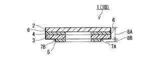
- the protective cover member 1B of FIGS. 2A and 2B has the same configuration as the protective cover member 1A except that the number of steps 7 is different.
- the outer peripheral surface 6 of the protective cover member 1B has two steps 7A and 7B.
- the steps 7A and 7B are formed in a part of the peripheral surface 6 in the circumferential direction.
- the steps 7A and 7B face each other with the center of the protective cover member 1B in between when viewed in the stacking direction.
- the protective cover member 1B can be removed by grasping the first portion 8A protruding outward at the step 7A and / or the first portion 8A protruding outward at the step 7B.
- FIG. 2B is a plan view of the protective cover member 1B of FIG. 2A as viewed from the first adhesive layer 5 side in the stacking direction.
- FIG. 2A shows a cross section AA of FIG. 2B.
- the protective cover member 1C shown in FIGS. 3A and 3B has the same configuration as the protective cover member 1A except that the shape of the step 7 is different.
- the step 7 of the protective cover member 1C is two line segments (R, S) extending inward from each of the two points (P, Q) on the outer circumference 9 of the first portion 8A when viewed in the stacking direction. It has a shape composed of.
- Each of the line segments (R and S) corresponds to a part of the side extending from one vertex T of the polygon.
- the polygon is a square or a rectangle, and the angle ⁇ PTQ at which the line segments (R, S) intersect is about 90 °.
- FIG. 3B is a plan view of the protective cover member 1C of FIG. 3A as viewed from the first adhesive layer 5 side in the stacking direction.
- FIG. 3A shows a cross section AA of FIG. 3B.
- the shapes of the protective cover members 1A, 1B, and 1C are circular when viewed in the stacking direction.
- the shape of the protective cover member 1 is not limited to the above example, and may be, for example, a polygon including a square and a rectangle, and an ellipse when viewed in the stacking direction.
- the polygon may be a regular polygon such as an equilateral triangle, a regular pentagon, a regular hexagon, a regular heptagon, and a regular octagon.
- the corners of the polygon may be rounded.
- FIGS. 4A and 4B An example of the protective cover member 1 having a rectangular shape is shown in FIGS. 4A and 4B.
- the protective cover member 1D of FIGS. 4A and 4B has the same configuration as the protective cover member 1A except that the shape seen in the stacking direction is rectangular.
- the step 7 of the protective cover member 1D extends linearly parallel to the short side of the outer circumference 9 of the rectangular first portion 8A when viewed in the stacking direction.
- the shape of the step 7 is not limited to this example.
- the step 7 may extend linearly non-parallel to the short side of the outer circumference 9 or may extend non-linearly (for example, curved) when viewed in the stacking direction, for example.
- the shape of the first portion 8A of the protective cover members 1A, 1B, 1C is a circle when viewed in the stacking direction, and the step 7 is such that the outer circumference 10 of the second portion 8B is inward of the outer circumference 9 of the first portion 8A. It is formed by retreating. Even when the shape of the first portion 8A is an ellipse or a regular polygon when viewed in the stacking direction, the step 7 means that the outer circumference 10 of the second portion 8B recedes inward from the outer circumference 9 of the first portion 8A. It may be formed by. In these aspects, since the width of the second portion 8B (the width seen in the stacking direction) is narrowed in the portion retracted inward, the removal by grasping the first portion 8A can be performed more reliably and stably. ..
- FIGS. 5A and 5B An example of the protective cover member 1 different from the above is shown in FIGS. 5A and 5B.
- the protective cover member 1E of FIGS. 5A and 5B has the same configuration as the protective cover member 1A except that the shape of the step 7 is different.
- the outer circumference 10 of the second portion 8B of the protective cover member 1E is a circle when viewed in the stacking direction, and the step 7 connects two points (P, Q) on the circle as an arc.
- the step 7 is formed by the outer circumference 9 of the first portion 8A projecting outward from the outer circumference 10 of the second portion 8B.
- the step 7 means that the outer circumference 9 of the first portion 8A protrudes outward from the outer circumference 10 of the second portion 8B. It may be formed by.
- the outer peripheral surface 6 may have a step 7 formed over the entire section in the circumferential direction.
- the depth D 1 of the region protruding outward in the first portion 8A is, for example, 0.1 to 20 mm, 0.5 to 20 mm, 1 to 15 mm, and further may be 1 to 10 mm.
- the depth D 1 corresponds to the maximum distance between the outer circumference 9 of the first portion 8A and the outer circumference 10 of the second portion 8B in the above region when viewed in the stacking direction.
- the maximum width (width seen in the stacking direction) W 1 of the above region is, for example, 0.1 to 20 mm, and 0.5 to 0.5. It may be 20 mm, 1 to 15 mm, and further 1 to 10 mm.
- the depth D 1 and the width W 1 may be larger values depending on the type of the object on which the protective cover member 1 is arranged.
- the protective cover member 1 can be removed from the object more reliably while suppressing damage.
- the degree of curl increases as the depth D 1 and / or the width W 1 , especially the depth D 1 , increases. Shows a tendency to increase.
- the ratio W 1 / D 1 of the width W 1 to the depth D 1 of the region protruding outward in the first portion 8A is, for example, 0.1 to 10, 0.5 to 8.0, and further 1. It may be 0 to 5.0.
- the ratio W 1 / D 1 is in the above range, the protective cover member 1 is more reliably removed from the object while suppressing damage.
- the area of the region protruding outward in the first portion 8A (the area seen in the stacking direction, the same applies hereinafter) is, for example, 3 to 50% and 5 to 40%, where the area of the first portion 8A is 100%. It may be.
- the first portion 8A has two or more of the above regions, the total area of each region may be within the above range.
- the protective cover member 1 can be more reliably removed from the object while suppressing damage.
- the protective film 2 may be non-breathable in the thickness direction or may have breathability in the thickness direction.
- the arrangement of the protective cover member 1 can ensure air permeability between the protective film 2 and the opening while preventing foreign matter from entering the opening.
- By ensuring the air permeability for example, it is possible to adjust the pressure through the opening of the object and mitigate the fluctuation of the pressure.
- mitigating pressure fluctuations is shown below.
- a heat treatment such as solder reflow may be performed in a state where the semiconductor element is arranged so as to cover one of the through holes provided in the circuit board.
- the protective cover member 1 By arranging the protective cover member 1 so as to cover the other opening, it is possible to suppress the invasion of foreign matter into the element through the through hole during the heat treatment.
- the protective film 2 has air permeability in the thickness direction, the pressure increase in the through hole due to heating is alleviated, and damage to the element due to the pressure increase can be prevented.
- semiconductor devices are micromechanical systems such as microphones, pressure sensors, and acceleration sensors (hereinafter referred to as “MEMS”). These elements have an opening capable of ventilating or passing sound, and the opening can be arranged on the circuit board so as to face the through hole.
- the air permeability of the protective film 2 having air permeability in the thickness direction was determined in accordance with the air permeability measurement method B (Garley type method) specified in Japanese Industrial Standards (hereinafter referred to as "JIS") L1096. Displayed by air permeability (hereinafter referred to as "Garley air permeability”), for example, 100 seconds / 100 mL or less.
- Examples of materials constituting the protective film 2 are metals, resins, and composite materials thereof.
- resins that can form the protective film 2 include polyolefins such as polyethylene and polypropylene, polyesters such as polyethylene terephthalate (PET), silicone resins, polycarbonates, polyimides, polyamideimides, polyphenylene sulfides, polyetheretherketones (PEEK), and fluoropolymers. It is a resin.
- fluororesins are PTFE, tetrafluoroethylene-perfluoroalkyl vinyl ether copolymer (PFA), tetrafluoroethylene-hexafluoropropylene copolymer (FEP), and tetrafluoroethylene-ethylene copolymer (ETFE). .
- the resin is not limited to the above example.
- Examples of metals that can form the protective film 2 are stainless steel and aluminum.
- the protective film 2 may be made of a heat-resistant material.
- heat resistant materials are metals and heat resistant resins.
- the thermostable resin typically has a melting point of 150 ° C. or higher.
- the melting point of the heat-resistant resin may be 160 ° C. or higher, 200 ° C. or higher, 250 ° C. or higher, 260 ° C. or higher, and further 300 ° C. or higher.
- heat-resistant resins are silicone resins, polyimides, polyamide-imides, polyphenylene sulfides, PEEKs and fluororesins.
- the fluororesin may be PTFE. PTFE is particularly excellent in heat resistance.
- the protective film 2 having air permeability in the thickness direction may include a stretched porous film.
- the stretched porous membrane may be a fluororesin stretched porous membrane, particularly a PTFE stretched porous membrane.
- the PTFE-stretched porous membrane is usually formed by stretching a paste extruded or cast membrane containing PTFE particles.
- the PTFE stretched porous membrane is composed of fine fibrils of PTFE, and may have nodes in which PTFE is in an aggregated state as compared with fibrils. According to the PTFE stretched porous membrane, it is possible to achieve both the performance of preventing the invasion of foreign substances and the air permeability at a high level.
- a known stretched porous film can be used as the protective film 2.
- the protective film 2 having air permeability in the thickness direction may include a perforated film in which a plurality of through holes connecting both main surfaces are formed.
- the perforated membrane may be a membrane having a non-porous substrate structure, for example, a non-porous membrane in which a plurality of through holes are provided.
- the perforated membrane may not have a ventilation path in the thickness direction other than the plurality of through holes.
- the through hole may extend in the thickness direction of the perforation membrane, or may be a straight hole extending linearly in the thickness direction.
- the shape of the through-hole opening may be circular or elliptical when viewed perpendicular to the main surface of the perforated membrane.
- the perforated membrane can be formed, for example, by laser processing the raw film, or by drilling by ion beam irradiation and subsequent chemical etching.
- the protective film 2 having breathability in the thickness direction may include a non-woven fabric, a woven fabric, a mesh, and a net.
- the protective film 2 is not limited to the above example.
- the shape of the protective film 2 of the protective cover members 1A to 1C and 1E is a circle when viewed in the stacking direction.
- the shape of the protective film 2 of the protective cover member 1D is rectangular when viewed in the stacking direction.
- the shape of the protective film 2 is not limited to the above example, and may be, for example, a polygon including a square and a rectangle, and an ellipse when viewed in the stacking direction.
- the polygon may be a regular polygon.
- the corners of the polygon may be rounded.
- the thickness of the protective film 2 is, for example, 1 to 100 ⁇ m.
- the area of the protective film 2 is, for example, 175 mm 2 or less.
- the protective cover member 1 in which the area of the protective film 2 is within the range is suitable for arrangement in, for example, a MEMS or a circuit board which usually has a small-diameter opening.
- the lower limit of the area of the protective film 2 is, for example, 0.20 mm 2 or more.
- the area of the protective film 2 may be a larger value depending on the type of the object on which the protective cover member 1 is arranged.
- Examples of materials constituting the base film 3 are metals, resins, and composite materials thereof. Specific examples of the materials that can form the base film 3 are the same as those of the materials that can form the protective film 2. The material constituting the protective film 2 and the material constituting the base film 3 may be different from each other.
- the base film 3 may be made of a heat-resistant material. In this case, depending on the material of the other layer constituting the protective cover member 1, it is possible to more reliably cope with the treatment under high temperature such as solder reflow. Specific examples of the heat-resistant material are as described above in the description of the protective film 2.
- the base film 3 of the protective cover members 1A to 1E has an outer circumference that coincides with the outer circumference of the protective film 2 when viewed in the laminating direction. Further, the base film 3 of the protective cover members 1A to 1E has a shape corresponding to the peripheral edge portion of the protective film 2 when viewed in the laminating direction.
- the protective cover members 1A to 1C and 1E have a ring shape, and the protective cover member 1D has a frame shape.
- the surface of the protective film 2 on the base film 3 side is exposed in the region where the base film 3 is not in contact.
- the protective film 2 has air permeability in the thickness direction, the region can be used as the air permeability region of the protective cover member 1.
- the shape of the base film 3 is not limited to the above example.
- the area of the ventilation area is, for example, 20 mm 2 or less.
- the protective cover member having an area of the ventilation region within the range is suitable for arrangement in, for example, a MEMS or a circuit board which usually has a small-diameter opening.
- the lower limit of the area of the ventilation region is, for example, 0.008 mm 2 or more.
- the area of the ventilation region may be a larger range depending on the type of the object on which the protective cover member 1 is arranged.
- the thickness of the base film 3 is, for example, 5 to 200 ⁇ m.
- the base film 3 of the protective cover members 1A to 1E is located between the protective film 2 and the first adhesive layer 5.
- the position of the base film 3 is not limited to this example.
- the base film 3 may be arranged on the upper surface of the protective film 2.
- the upper surface means a surface farther from the object when the protective cover member is arranged on the surface of the object.
- the lower surface means a surface closer to the object when the protective cover member is arranged on the surface of the object.
- the base film 3 may have higher strength than the protective film 2. In this case, damage to the protective film 2 when the protective cover member 1 is removed can be more reliably suppressed.
- the strength can be evaluated as, for example, tensile breaking strength or cohesive breaking strength.
- the protective film 2 of the protective cover members 1A to 1E and the base film 3 are joined by a second adhesive layer 4.
- the second adhesive layer 4 is, for example, an adhesive or an adhesive coating layer.
- the pressure-sensitive adhesive are an acrylic pressure-sensitive adhesive, a silicone-based pressure-sensitive adhesive, a urethane-based pressure-sensitive adhesive, an epoxy-based pressure-sensitive adhesive, and a rubber-based pressure-sensitive adhesive.
- an acrylic pressure-sensitive adhesive or a silicone-based pressure-sensitive adhesive particularly a silicone-based pressure-sensitive adhesive, which has excellent heat resistance.
- the acrylic pressure-sensitive adhesive is, for example, a pressure-sensitive adhesive disclosed in JP-A-2005-105212.
- the silicone-based pressure-sensitive adhesive is, for example, a pressure-sensitive adhesive disclosed in JP-A-2003-313516 (including those disclosed as comparative examples).
- the second adhesive layer 4 may be a single layer or may have a laminated structure including two or more adhesive layers.
- the second adhesive layer 4 may be a double-sided adhesive tape.
- the double-sided adhesive tape may be a base material-containing tape having a base material and adhesive layers provided on both surfaces of the base material, or may be a base material-less tape containing no base material.
- the second adhesive layer 4 is further formed by applying a single-sided adhesive tape having an adhesive layer provided on one side of the base material and the base material and an adhesive on the surface of the base material opposite to the adhesive layer side. It may have a laminated structure with an adhesive layer.
- the base material and the pressure-sensitive adhesive layer of the adhesive tape may be used as the base material film 3 and the second pressure-sensitive adhesive layer 4, respectively.
- the base film 3 does not have to be the layer contained in the adhesive tape.
- the base material of the adhesive tape is, for example, a film, non-woven fabric or foam of resin, metal or a composite material thereof.
- the base material of the adhesive tape may be composed of a heat resistant material. In this case, depending on the material of the other layer constituting the protective cover member 1, it is possible to more reliably cope with the treatment under high temperature such as solder reflow. Specific examples of the heat-resistant material are as described above in the description of the protective film 2.
- the shape of the second adhesive layer 4 of the protective cover members 1A to 1E is the same as the shape of the base film 3 when viewed in the laminating direction.
- the shape of the second adhesive layer 4 is not limited to this example.
- the protective film 2 and the base film 3 may be bonded by a second adhesive layer 4 having a dot-like, lattice-like, or wavy shape when viewed in the stacking direction.
- the method of joining the protective film 2 and the base film 3 is not limited to the above example.
- the protective film 2 and the base film 3 may be bonded by various welding methods such as heat welding and ultrasonic welding without passing through the second adhesive layer 4.
- the outwardly protruding region of the first portion 8A is separated from the surface of the object (hereinafter, the direction is referred to as “the direction”. It can be bent (curled) (described as "upper").
- the first portion 8A may have a configuration in which the region protruding outward at the step 7 can be curled upward by heating. By curling upward, the protective cover member 1 can be removed more reliably.
- the upward curl can be generated, for example, by selecting the protective film 2 and / or the base film 3 as follows.
- the method of generating curl is not limited to these examples.
- a protective film 2 having a relatively small coefficient of thermal expansion and a base film 3 having a relatively large coefficient of thermal expansion are selected. The difference in the coefficient of thermal expansion between the two bonded layers causes curl.
- a film having holes and / or through holes is selected.
- a specific example of the membrane is a membrane having air permeability in the thickness direction. Membranes with pores and / or through holes tend to shrink due to heat. The shrinkage causes curl.
- the first portion 8A is a circle, an ellipse, or a regular polygon when viewed in the stacking direction, and a step 7 is formed by the outer circumference 10 of the second portion 8B retracting inward from the outer circumference 9 of the first portion. If it is, curling is likely to occur. Further, when the step 7 extends linearly when viewed in the stacking direction, curl is likely to occur.
- the protective cover member 1 when the member 1 is fixed to the surface of a stainless steel plate and heat-treated from 25 ° C. to 260 ° C. at a heating rate of 1 ° C./sec, it occurs in an outwardly protruding region in the first portion 8A.
- the degree of curl may be 110% or more, 130% or more, 200% or more, 250% or more, 300% or more, 350% or more, 400% or more, and further 450% or more, expressed by the curl rate. It may be.
- the protective cover member 1 is fixed to the stainless steel plate by the first adhesive layer 5.
- the upper surface and / or lower surface of the outwardly protruding region in the first portion 8A is preferably non-adhesive. In this case, it is possible to prevent the jig or hand for removing the protective cover member 1 from adhering to the region, and the protective cover member 1 can be removed more reliably and stably.
- the first adhesive layer 5 may have the same structure as the second adhesive layer 4 except for its shape.
- the first adhesive layer 5 may be composed of a double-sided adhesive tape, and further, the adhesive is applied to the single-sided adhesive tape and the surface of the base material on the opposite side of the tape to the adhesive layer side. It may have a laminated structure with an adhesive layer.
- the further adhesive layer may be located on the protective film 2 side or on the placement surface side with respect to the object.
- the side of the first adhesive layer 5 in contact with the object may be a weakly adhesive surface. In this case, the protective cover member 1 can be removed with a smaller force.
- the first adhesive layer 5 of the protective cover members 1A to 1E is located in the second portion 8B.
- the position of the first adhesive layer 5 is not limited to this example.
- the first adhesive layer 5 may be located closer to the object than the second portion 8B when the protective cover member 1 is arranged on the surface of the object.
- the first adhesive layer 5 of the protective cover members 1A to 1E has a shape that surrounds the opening of the object when viewed in the stacking direction when the protective cover member 1 is arranged on the surface of the object.
- the shape of the first adhesive layer 5 is not limited to the above example as long as the protective cover member 1 can be fixed to the object.
- the thickness of the first adhesive layer 5 is, for example, 10 to 200 ⁇ m.
- the area of the protective cover member 1 is, for example, 175 mm 2 or less.
- the protective cover member 1 having an area within the range is suitable for arrangement in, for example, a MEMS or a circuit board which usually has a small-diameter opening.
- the lower limit of the area of the protective cover member 1 is, for example, 0.20 mm 2 or more.
- the area of the protective cover member 1 may be a larger value depending on the type of the object to be arranged. The smaller the area of the protective cover member 1, the more difficult it is to remove. Therefore, the effect of the present invention becomes particularly remarkable when the area of the protective cover member 1 is within the above range.
- the protective cover member 1 may include any layer other than those described above as long as the effects of the present invention can be obtained.
- the object on which the protective cover member 1 can be placed is, for example, the circuit board described above.
- the object may be a semiconductor element such as MEMS.
- the MEMS may be a non-sealing device having ventilation holes on the surface of the package.
- the pore size of the MEMS vent is usually small.
- Examples of non-sealed MEMS are various sensors that detect atmospheric pressure, humidity, gas, airflow, etc., and electroacoustic conversion elements such as speakers and microphones.
- the object is not limited to the above example.
- the surface of the object on which the protective cover member 1 can be placed is typically the surface of the object.
- the surface may be a flat surface or a curved surface.
- the opening of the object may be an opening of a recess or an opening of a through hole.
- the treatment of the object on which the protective cover member 1 is arranged may be a treatment under a high temperature or a low temperature.
- the protective cover member 1 can be manufactured, for example, by shaping and laminating the protective film 2, the base film 3, and the first adhesive layer 5.
- the protective cover member 1 can be supplied in a state of being arranged on a release sheet such as a release paper or a release liner.
- a plurality of protective cover members 1 may be arranged on the release sheet.
- An adhesive layer (for example, the first adhesive layer 5) included in the protective cover member 1 may be used for arrangement on the release sheet.
- a weak adhesive layer may be provided on the surface of the release sheet on which the protective cover member 1 is arranged, and the protective cover member 1 may be arranged via the weak adhesive layer.
- a member supply sheet in which the release sheet is a base sheet will be described later.
- FIG. 6 shows an example of the mode in which the protective cover member 1 is used.
- the protective cover member 1 is arranged on the surface 33 of the object 31 having the opening 32 so that the protective film 2 covers the opening 32.
- the protective cover member 1 is usually arranged so that the first adhesive layer 5 does not cover the opening 32 when viewed in the stacking direction.
- a predetermined process is performed on the object 31 on which the protective cover member 1 is arranged (FIG. 6 (b)). After the treatment, the protective cover member 1 is removed from the surface 33 (FIG. 6 (c)).
- the mode in which the protective cover member 1 is used is not limited to the above example.
- the protective cover member 1 does not necessarily have to be removed and may remain on the surface 33. It is also possible to distribute or use the object 31 while remaining on the surface 33.
- the protective cover member 1 can be removed at any time after the distribution and / or use of the object.
- a protective cover member that is arranged on the surface of an object having a surface having an opening to prevent foreign matter from entering the opening.
- a part of the surface to be arranged on the object is a low adhesive surface and / or a non-adhesive surface. Therefore, the member can be removed while suppressing damage by smoother peeling from the object triggered by the low adhesive surface and / or the non-adhesive surface. Therefore, it is possible to remove the object while suppressing damage.
- the layers and members included in the second protective cover member are designated by the same reference numerals and duplicated description will be omitted.
- FIGS. 7A and 7B An example of the second protective cover member is shown in FIGS. 7A and 7B.
- FIG. 7B is a plan view of the protective cover member 51 (51A) of FIG. 7A as viewed from the third adhesive layer 52 side (arrangement surface 60 side to the object).
- FIG. 7A shows a cross section AA of FIG. 7B.
- the protective cover member 51A is a member that is arranged on the surface of an object having a surface having an opening to prevent foreign matter from entering the opening.
- the protective cover member 51A is composed of a laminated body including the protective film 2 and the third adhesive layer 52.
- the protective film 2 has a shape that covers the opening when the protective cover member 51A is arranged on the surface.
- the protective film 2 and the third adhesive layer 52 are bonded to each other.
- the protective cover member 51A is fixed to the above surface by the third adhesive layer 52.
- a part (part 61) of the arrangement surface 60 of the protective cover member 51A is a low adhesive surface and / or a non-adhesive surface, preferably a non-adhesive surface.
- the low adhesive surface means a surface having lower adhesiveness than the other portion 62 of the arrangement surface 60.
- the portion 61 of the protective cover member 51A may be a treated surface of the third adhesive layer 52 having reduced adhesiveness.
- the treated surface may be a deactivated surface that has lost its adhesiveness.
- the treated surface of the adhesive layer can be formed by, for example, the following method. However, the method of forming the treated surface is not limited to the examples shown below.
- the portion of the adhesive layer to be treated is plasma-treated. The plasma treatment deteriorates the adhesive contained in the portion, whereby a treated surface is formed.
- the pressure-sensitive adhesive polymer contained in the portion of the pressure-sensitive adhesive layer to be treated is subjected to further polymerization treatment such as graft polymerization or copolymerization to modify the portion.
- the adhesive layer is impregnated with an ultraviolet absorber and / or a heat foaming agent, and the portion to be treated is irradiated with ultraviolet rays and / or heat is applied to denature the portion.
- An adhesive lowering agent is brought into contact with the portion of the adhesive layer to be treated.
- the tackiness reducing agent is a solution containing, for example, a silicone compound when the pressure-sensitive adhesive layer is acrylic. The contact can be carried out, for example, by coating or spraying.
- the portion 61 of the protective cover member 51A includes a line 64 connecting a part EF of the outer peripheral 63 of the arrangement surface 60 and both ends (E, F) of the section EF when viewed in the stacking direction of the laminated body. Surrounded by.
- the line 64 constitutes the boundary between the portion 61 and the portion 62.
- the outer circumference 63 is a circle when viewed in the stacking direction, and the straight line 64 connects both ends (E, F) as strings.
- the central angles ⁇ of both ends (E, F) are about 90 °.
- the protective cover member 51A and its arrangement surface 60 have one portion 61.
- the protective cover member 51A and the arrangement surface 60 may have two or more portions 61.
- the line 64 may be a non-straight line, for example, a curved line, or both ends (E, F) may be connected in a zigzag shape.
- the central angle ⁇ is not limited to 90 °.
- the maximum width (width seen in the stacking direction) W 2 of the portion 61 is, for example, 0.1 to 20 mm, 0.5 to 20 mm, 1 to 15 mm, and further 1 to 10 mm.
- the depth D 2 of the portion 61 is, for example, 0.1 to 20 mm, and may be 0.5 to 20 mm, 1 to 15 mm, and further 1 to 10 mm. Depth D 2 corresponds to the maximum distance between the outer circumference 63 and the line 64 when viewed in the stacking direction. However, the width W 2 and the depth D 2 may be larger values depending on the type of the object on which the protective cover member 51A is arranged.
- the protective cover member 51 can be removed from the object more reliably while suppressing damage. Further, with respect to the portion 61, in the protective cover member 51 in which the curl described later is generated by the treatment at a high temperature, the degree of curl (curl rate) increases as the depth D 2 and / or the width W 2 , especially the depth D 2 , increases. Shows a tendency to increase.
- the ratio W 2 / D 2 of the width W 2 relative to the depth D 2 of the portion 61 is, for example, 0.1 to 10, 0.5-8.0, or may be a 1.0-5.0 ..
- the ratio W 2 / D 2 is in the above range, the protective cover member 51 can be removed from the object more reliably while suppressing damage.
- the area of the portion 61 (the area seen in the stacking direction, the same applies hereinafter) is, for example, 3 to 50%, and may be 5 to 40%, where the area of the arrangement surface 60 is 100%.
- the arrangement surface 60 has two or more portions 61, the total area of each portion 61 may be within the above range.
- the area of the portion 61 is within these ranges, the removal from the object is more reliable while suppressing damage to the protective cover member 51.
- the third adhesive layer 52 may have the same structure as the first adhesive layer 5 and / or the second adhesive layer 4 of the first protective cover member 1 as long as it has the portion 61.
- the arrangement surface of the first adhesive layer 5 in the first protective cover member 1 may have a portion 61.
- the surface of the protective film 2 on the third adhesive layer 52 side is exposed in the region where the third adhesive layer 52 is not in contact.
- the region can be used as the air permeability region of the protective cover member 51A.
- the area of the ventilation area is, for example, 20 mm 2 or less.
- the protective cover member having an area of the ventilation region within the range is suitable for arrangement in, for example, a MEMS or a circuit board which usually has a small-diameter opening.
- the lower limit of the area of the ventilation region is, for example, 0.008 mm 2 or more.
- the area of the ventilation region may be a larger range depending on the type of the object on which the protective cover member 51A is arranged.
- the aspect of the portion 61 is not limited to the above example as long as it has a low adhesive surface and / or a non-adhesive surface. Examples of different aspects of the portion 61 are shown in FIGS. 8A-11.
- the protective cover member 51 (51B) of FIGS. 8A and 8B is protected except that the portion 61 is formed by the member 53 arranged on the main surface 65 of the third adhesive layer 52 opposite to the protective film 2 side. It has the same configuration as the cover member 51A.
- the member 53 has a low adhesive surface and / or a non-adhesive surface on the surface constituting the arrangement surface 60 in a state of being arranged on the main surface 65. An adhesive layer may not be formed on the surface of the member 53 that constitutes the arrangement surface 60.
- the member 53 may be made of a low-adhesive and / or non-adhesive material.
- the low-adhesive material means that the material has a low adhesiveness as compared with the material constituting the other portion 62 of the arrangement surface 60.
- the member 53 is, for example, a film.
- the film constituting the member 53 may have the same configuration as the base film 3 of the first protective cover member 1 except for its shape.
- the member 53 may be made of a heat-resistant material. Specific examples of the heat-resistant material are as described above in the description of the protective film 2.
- the thickness of the member 53 is, for example, 5 to 100 ⁇ m.
- the third adhesive layer 52 is arranged so as to overlap a part region 66 of the protective film 2.
- a member 54 different from the third adhesive layer 52 is arranged so as to overlap with the other part 67 of the protective film 2, and the same as the protective cover member 51A except that the portion 61 is composed of the member 54. It has the structure of.
- the arrangement surface 60 of FIGS. 9A and 9B is composed of a third adhesive layer 52 and a member 54. However, the arrangement surface 60 may be composed of a third adhesive layer 52, a member 54, and other additional members.
- the member 54 may have the same configuration as the member 53.
- the thickness of the member 54 is, for example, 5 to 100 ⁇ m.
- the thickness of the member 54 may be the same as the thickness of the third adhesive layer 52.
- the protective cover member 51 (51D) of FIG. 10 has the same configuration as the protective cover member 51A except that the number and arrangement of the portions 61 are different.
- the arrangement surface 60 of the protective cover member 51D has two portions 61 (61A, 61B).
- the shapes of the respective portions 61A and 61B are the same as those of the portion 61 of the protective cover member 51A.
- the portions 61A and 61B face each other with the center of the protective cover member 51D interposed therebetween.
- the protective cover member 51D can be removed more smoothly from either the portion 61A side or the portion 61B side.
- the protective cover member 51 (51E) of FIG. 11 has the same configuration as the protective cover member 51A except that the shape of the portion 61 is different.
- the portion 61 of the protective cover member 51E extends inward from each of a part EF of the outer circumference 63 of the arrangement surface 60 and both ends (E, F) of the section EF when viewed in the stacking direction. It is surrounded by a line 64 connecting both ends (E, F) composed of two intersecting line segments (H, G).
- Each line segment (H, G) corresponds to a part of an edge extending from one vertex I of the polygon.
- the polygon is a square or a rectangle, and the angle ⁇ EIF where the line segments (H, G) intersect is about 90 °.
- the polygon is not limited to a square and a rectangle, and the angle ⁇ EIF does not have to be 90 °.
- the shape of the protective cover members 51A to 51E is a circle when viewed in the stacking direction.
- the shape of the protective cover member 51 is not limited to the above example, and may be, for example, a polygon including a square and a rectangle, and an ellipse when viewed in the stacking direction.
- the polygon may be a regular polygon such as an equilateral triangle, a regular pentagon, a regular hexagon, a regular heptagon, and a regular octagon.
- the corners of the polygon may be rounded.
- FIG. 12 shows an example of the protective cover member 51 having a rectangular shape.
- the protective cover member 51F of FIG. 12 has the same configuration as the protective cover member 51A except that the shape seen in the stacking direction is rectangular.
- the portion 61 of the protective cover member 51F is rectangular when viewed in the stacking direction.
- the straight line 64 extends in the direction of the short side of the protective cover member 51F when viewed in the stacking direction.
- the shape of the portion 61 is not limited to this example. Further, the line 64 may be a straight line non-parallel to the short side or a non-straight line (for example, a curved line) when viewed in the stacking direction.
- the protective cover member 51 may include any layer other than those described above as long as the effects of the present invention can be obtained.
- FIG. 13 shows an example of the protective cover member 51 having a layer other than the above.
- the laminated body of the protective cover member 51G of FIG. 13 further includes a base film 55 and a fourth adhesive layer 56.
- the base film 55 is bonded to the protective film 2 by the fourth adhesive layer 56.
- a third adhesive layer 52 is provided on the surface of the base film 55 opposite to the protective film 2 side.
- the base film 55 is located between the protective film 2 and the third adhesive layer 52.
- the base film 55 reinforces the protective film 2 when the protective cover member 51 is removed from the surface of the object.
- FIG. 14 shows another example of the protective cover member 51 having a layer other than the above.
- the protective cover member 51H of FIG. 14 is the same as the protective cover member 51G except that the portion 61 is formed by the member 53 arranged on the main surface 65 on the side opposite to the base film 55 side of the third adhesive layer 52. It has the structure of.
- the possible configurations of the member 53 are as described above.
- the base film 55 may have the same structure as the base film 3.
- the fourth adhesive layer 56 may have the same structure as the second adhesive layer 4.
- the area of the protective cover member 51 may have the same range as that of the first protective cover member 1. However, the area of the protective cover member 51 may be a larger value than the above range depending on the type of the object to be arranged. It should be noted that the smaller the area of the protective cover member 51, the more difficult it is to remove, which is the same as that of the first protective cover member 1.
- the portion 61 is bent upward by, for example, processing at a high temperature, depending on the combination of the protective film 2 and the base film 55, as in the case of the protective cover member 1. Can be curled). In other words, the protective cover member 51 may have a structure in which the portion 61 can be curled upward. By curling upward, the protective cover member 51 can be removed more reliably.
- the example of the combination of the protective film 2 and the base film 55 is the same as the example of the combination of the protective film 2 and the base film 3 in the protective cover member 1.
- the degree of curl that can occur in the portion 61 when the member 51 is fixed to the surface of a stainless steel plate and heat-treated from 25 ° C. to 260 ° C. at a heating rate of 1 ° C./sec depends on the curl rate. It may be displayed as 110% or more, 130% or more, 200% or more, 250% or more, and further 290% or more.
- the protective cover member 51 is fixed to the stainless steel plate by the third adhesive layer 52.
- the surface of the object and the object on which the protective cover member 51 can be arranged, and the processing of the object on which the protective cover member 51 is arranged are the same as those of the first protective cover member 1.
- the protective cover member 51 can be manufactured, for example, by shaping and laminating the protective film 2 and the third adhesive layer 52, and forming a portion 61 on the arrangement surface 60.
- the protective cover member 51 can be supplied in a state of being arranged on a release sheet such as a release paper or a release liner, similarly to the first protective cover member 1.
- the specific aspect is the same as in the case of the first protective cover member 1.
- FIG. 15 shows an example of the mode in which the protective cover member 51 is used.
- a protective cover member 51 is arranged on the surface 33 of the object 31 having the opening 32 so that the protective film 2 covers the opening 32.
- the protective cover member 51 is usually arranged so that the third adhesive layer 52 does not cover the opening 32 when viewed in the stacking direction.
- a predetermined process is performed on the object 31 on which the protective cover member 51 is arranged (FIG. 15 (b)).
- the protective cover member 51 is removed from the surface 33 (FIG. 15 (c)). The removal can be performed from the portion 61 side of the arrangement surface 60 of the protective cover member 51.
- the mode in which the protective cover member 51 is used is not limited to the above example, as in the case of the first protective cover member 1.
- This disclosure discloses the second protective cover member shown in each of the following items ⁇ to ⁇ .
- a protective cover member that is arranged on the surface of an object having a surface having an opening to prevent foreign matter from entering the opening.
- a protective cover member in which a part of the surface of the protective cover member arranged on the surface is a low-adhesive surface and / or a non-adhesive surface.
- the adhesive layer is arranged so as to overlap a part of the area of the protective film, and a further member different from the adhesive layer is arranged so as to overlap with another part of the protective film.
- Item 2 The protective cover member according to Item ⁇ , wherein a part of the arrangement surface is composed of the further member.
- FIG. 16 An example of the member supply sheet of the present invention is shown in FIG.
- the member supply sheet 11 of FIG. 16 includes a base sheet 12 and a plurality of protective cover members 1 arranged on the base sheet 12.
- the member supply sheet 11 is a sheet for supplying the protective cover member 1. According to the member supply sheet 11, for example, the protective cover member 1 can be efficiently supplied to the step of arranging the protective cover member 1 on the surface of the object.
- two or more protective cover members 1 are arranged on the base sheet 12.
- the number of the protective cover member 1 arranged on the base sheet 12 may be one.
- Examples of materials constituting the base sheet 12 are paper, metal, resin, and composite materials thereof.
- the metal is, for example, stainless steel and aluminum.
- the resin is, for example, polyester such as PET, polyethylene, and polyolefin such as polypropylene.
- the material constituting the base sheet 12 is not limited to the above example.
- the protective cover member 1 may be arranged on the base sheet 12 via an adhesive layer (for example, the first adhesive layer 5) included in the member 1. At this time, the surface on which the protective cover member 1 is arranged on the base sheet 12 may be subjected to a mold release treatment for improving the releasability from the base sheet 12.
- the mold release treatment can be carried out by a known method.
- the protective cover member 1 may be arranged on the base sheet 12 via an adhesive layer provided on the arrangement surface of the protective cover member 1 in the base sheet 12, typically a weak adhesive layer.
- the thickness of the base sheet 12 is, for example, 1 to 200 ⁇ m.
- the member supply sheet 11 and the base material sheet 12 in FIG. 16 are strip-shaped.
- the plurality of protective cover members 1 are arranged in series on the strip-shaped base sheet 12 in one direction (the direction in which the base sheet 12 extends).
- the shape of the member supply sheet 11, the shape of the base sheet 12, and the form of arrangement of the protective cover member 1 on the base sheet 12 are not limited to this example.
- a single-wafer-shaped member supply sheet 11 and / or a base sheet 12 having various shapes such as polygons including rectangles and squares, circles, and ellipses may be used.
- the plurality of protective cover members 1 may be arranged in a staggered pattern when viewed perpendicular to the arrangement surface, or the center of the protective cover member 1 may be an intersection (lattice point) of a virtual lattice on the arrangement surface. It may be regularly arranged so as to be located at. Examples of grids are square grids, orthorhombic grids, and rhombic grids.
- the strip-shaped member supply sheet 11 may be a winding body (reel) wound around a winding core.
- the center of the protective cover member 1 can be defined as the center of gravity of the shape of the member 1 when viewed perpendicularly to the surface of the base sheet 12.
- the member supply sheet 11 can be manufactured by arranging the protective cover member 1 on the base sheet 12.
- the protective cover member arranged on the base material sheet 12 may be a second protective cover member 51 instead of the first protective cover member 1.
- the mode that the member supply sheet of the present invention can take is the same regardless of whether the protective cover member to be arranged is the first protective cover member 1 or the second protective cover member 51. Further, both the first protective cover member 1 and the second protective cover member 51 may be arranged on the base sheet 12.
- the member supply sheet of the present invention includes a base sheet 12 and one or more first protective cover members 1 and / or second protective cover members 51 arranged on the base sheet 12.
- the measurement temperature was 25 ⁇ 5 ° C. and the measurement humidity was 65 ⁇ 20% RH.
- the coefficient of linear expansion ⁇ (160-200 ° C.) of the protective film and the base film was evaluated by thermomechanical analysis (TMA) using a thermal analyzer (NETZSCH, TMA4000SA).
- TMA thermomechanical analysis
- the shape of the test piece was a rectangle having a width of 4 mm and a length of 25 mm.
- the prepared test piece was attached to the above thermal analyzer and heated from 25 ° C. to 260 ° C. at a heating rate of 10 ° C./min while applying a constant tensile load (0.5 gf) in the length direction of the test piece. From the TMA curve (horizontal axis: temperature, vertical axis: length of test piece), the coefficient of linear expansion was calculated by the following formula.
- T 1 160 ° C
- T 2 200 ° C
- L 0 is the initial length of the test piece
- L 1 is the length of the test piece at temperature T 1
- L 2 is the length of the test piece at temperature T 2 . Is.
- the air permeability in the thickness direction of the protective film was determined as the Garley air permeability in accordance with the air permeability measurement method B (Garley type method) specified in JIS L1096.
- the curl rate is such that a part of the area or part of the member bends (curls) in the direction away from the surface of the object (upward).
- the produced protective cover member was fixed to the surface of the stainless steel plate via an adhesive layer exposed on the surface opposite to the protective film.
- the protective cover member together with the stainless steel plate was housed in a static reflow furnace (SAR500A manufactured by Okuhara Electric Co., Ltd.) and heat-treated from 25 ° C. to 260 ° C. at a heating rate of 1 ° C./sec.
- SAR500A manufactured by Okuhara Electric Co., Ltd.
- the degree of curling of the above-mentioned part or part before and after the heat treatment was observed from the side of the protective cover member using a digital microscope (manufactured by Nikon, PMFSC).
- the peeling workability of the protective cover member was evaluated as follows.
- the produced protective cover member was fixed to the surface of the polychlorinated biphenyl plate via an adhesive layer exposed on the surface opposite to the protective film.
- the protective cover member together with the polychlorinated biphenyl plate was housed in a static reflow furnace (SAR500A manufactured by Okuhara Electric Co., Ltd.) and heat-treated from 25 ° C. to 260 ° C. at a heating rate of 1 ° C./sec.
- the protective cover member of Comparative Example 1 does not have the first portion 8A and the portion 61, it was peeled off by gripping the side surface of the member.
- the protective cover member of Comparative Example 2 was attempted to be peeled off by gripping an outwardly protruding portion of the protective film.
- a PTFE stretched porous film A was prepared as follows. 100 parts by weight of PTFE fine powder (manufactured by Daikin Industries, Ltd., Polyflon PTFE F-104) and 20 parts by weight of n-dodecane (manufactured by Japan Energy) as a molding aid are uniformly mixed, and the obtained mixture is mixed using a cylinder. After compression, lamb extrusion was performed to form a sheet-like mixture. Next, the formed sheet-like mixture was rolled through a pair of metal rolls to a thickness of 0.15 mm, and the molding aid was further removed by heating at 150 ° C. to form a strip-shaped PTFE sheet molded body.
- PTFE fine powder manufactured by Daikin Industries, Ltd., Polyflon PTFE F-104
- n-dodecane manufactured by Japan Energy
- the formed sheet molded body was stretched in the longitudinal direction at a stretching temperature of 360 ° C. and a stretching ratio of 10 times, and then stretched in the width direction at a stretching temperature of 150 ° C. and a stretching ratio of 10 times to obtain a PTFE stretched porous film A.
- the thickness of the PTFE stretched porous membrane A was 25 ⁇ m
- the air permeability in the thickness direction was 0.2 seconds / 100 mL in terms of Garley air permeability
- the coefficient of linear expansion was -393 ⁇ 10 -6 / ° C.
- a PTFE-stretched porous film B was prepared as follows. PTFE dispersion (40% by weight of PTFE powder, 0.2 ⁇ m average particle size of PTFE powder, 6 parts by weight of nonionic surfactant with respect to 100 parts by weight of PTFE) and fluorine-based surfactant (manufactured by DIC) , Megafuck F-142D) was added in an amount of 1 part by weight based on 100 parts by weight of PTFE. Next, a long polyimide film (thickness 125 ⁇ m) was immersed in the PTFE dispersion and pulled up to form a coating film of the PTFE dispersion on the film.
- the thickness of the coating film was set to 20 ⁇ m by the measuring bar.
- the coating film is heated at 100 ° C. for 1 minute and then at 390 ° C. for 1 minute to evaporate and remove the water contained in the dispersion, and the remaining PTFE particles are bound to each other to form a PTFE film.
- the PTFE film (thickness 25 ⁇ m) was peeled off from the polyimide film.
- the obtained PTFE film was stretched with a tenter at a stretching ratio of 2 times in the width direction. Further, the PTFE film was rolled at a rolling magnification of 2.5 times in the longitudinal direction.
- a PTFE-stretched porous membrane B was obtained.
- the set temperature of the roll in the roll rolling apparatus was 170 ° C.
- the stretching temperature was 170 ° C.
- the thickness of the PTFE stretched porous membrane B was 10 ⁇ m, the air permeability in the thickness direction was 100 seconds / 100 mL in terms of Garley air permeability, and the coefficient of linear expansion was ⁇ 750 ⁇ 10 -6 / ° C.
- a polyimide film (manufactured by Toray DuPont, Kapton) was prepared as a base film.
- the thickness of the base film was 25 ⁇ m, and the coefficient of linear expansion was 14 ⁇ 10 -6 / ° C.
- Example 1 The PTFE-stretched porous film A and the base film were joined with a silicone pressure-sensitive adhesive (manufactured by Dow Toray, SH4280, which is a peroxide-curable type, 1.2 parts by weight of peroxide) to form a laminate.
- the curing conditions of the silicone adhesive were 200 ° C. and 3 minutes.
- the thickness of the adhesive layer (second adhesive layer 4) made of the silicone adhesive was 25 ⁇ m.
- the laminate was cut into rectangles having a width of 10 mm and a length of 100 mm to form the first portion 8A.
- a double-sided adhesive tape manufactured by Nitto Denko, No.
- Example 2 The laminate prepared in the same manner as in Example 1 was cut into a rectangle having a width of 5 mm and a length of 50 mm to form the first portion 8A.
- a double-sided adhesive tape manufactured by Nitto Denko, No. 585, thickness 50 ⁇ m
- the joining of the first adhesive layer 5 was carried out so that one short side and both long sides coincide with each other between the first portion 8A and the first adhesive layer 5.
- the rectangular protective cover member shown in FIGS. 4A and 4B (the width W 1 of the region protruding outward in the first portion 8A is 5 mm, the depth D 1 is 5 mm, and the area A 1 is 25 mm 2 ). Obtained.
- Example 3 The laminate prepared in the same manner as in Example 1 was cut into a rectangle having a width of 2.5 mm and a length of 25 mm to form the first portion 8A.
- a double-sided adhesive tape manufactured by Nitto Denko, No. 585, thickness 50 ⁇ m
- the joining of the first adhesive layer 5 was carried out so that one short side and both long sides coincide with each other between the first portion 8A and the first adhesive layer 5.
- the rectangular protective cover member shown in FIGS. 4A and 4B (the width W 1 of the region protruding outward in the first portion 8A is 2.5 mm, the depth D 1 is 0.5 mm, and the area A 1 is 1.25 mm 2 ) was obtained.
- Example 4 The laminate prepared in the same manner as in Example 1 was cut into a rectangle having a width of 1.0 mm and a length of 10 mm to form the first portion 8A.
- a double-sided adhesive tape manufactured by Nitto Denko, No. 585, thickness 50 ⁇ m
- the joining of the first adhesive layer 5 was carried out so that one short side and both long sides coincide with each other between the first portion 8A and the first adhesive layer 5.
- the rectangular protective cover member shown in FIGS. 4A and 4B (the width W 1 of the region protruding outward in the first portion 8A is 1.0 mm, the depth D 1 is 0.5 mm, and the area A 1 is 0.5 mm 2 ) was obtained.
- Example 1 The laminate prepared in the same manner as in Example 1 was cut into rectangles having a width of 10 mm and a length of 100 mm. Next, a double-sided adhesive tape (manufactured by Nitto Denko, No. 585, thickness 50 ⁇ m) cut out into a rectangle having a width of 10 mm and a length of 100 mm was bonded to the base film as an adhesive layer. The bonding of the adhesive layers was carried out so that the outer periphery of the laminated body and the outer periphery of the adhesive layer coincide with each other when viewed in the laminating direction of the laminated body. In this way, a rectangular protective cover member having no outwardly protruding region was obtained.
- a double-sided adhesive tape manufactured by Nitto Denko, No. 585, thickness 50 ⁇ m
- Example 2 The laminate prepared in the same manner as in Example 1 was cut into rectangles having a width of 10 mm and a length of 100 mm. Next, a double-sided adhesive tape (manufactured by Nitto Denko, No. 585, thickness 50 ⁇ m) cut out into a rectangle having a width of 10 mm and a length of 100 mm was bonded to the base film as a third adhesive layer 52. The joining of the third adhesive layer 52 was carried out so that the outer periphery of the laminated body and the outer periphery of the third adhesive layer 52 coincided with each other when viewed in the laminating direction of the laminated body.
- a double-sided adhesive tape manufactured by Nitto Denko, No. 585, thickness 50 ⁇ m
- a further polyimide film manufactured by Toray DuPont, Kapton, thickness 25 ⁇ m
- the arrangement was carried out so that the three sides of the polyimide film, one short side of the third adhesive layer 52, and the long sides of both coincide with each other.
- the rectangular protective cover member shown in FIG. 14 (the width W 2 of the portion 61 is 10 mm and the depth D 2) is formed on the adhesive surface 60 by the polyimide film which is the member 53. 10 mm and the area A 2 was 100 mm 2 ).
- PTFE stretched porous film A width 10 mm and length 120 mm
- the silicone adhesive used in Example 1 was joined to obtain a laminate.
- the curing conditions of the silicone adhesive were the same as in Example 1.
- the thickness of the pressure-sensitive adhesive layer 102 made of the silicone pressure-sensitive adhesive was 25 ⁇ m. The joining was carried out so that the long sides and the centers of the base film 103 and the protective film 101 coincided with each other when viewed in the laminating direction of the laminated body.
- a double-sided adhesive tape manufactured by Nitto Denko, No. 585, thickness 50 ⁇ m
- the bonding of the adhesive layer 104 was carried out so that the outer circumference of the base film 103 and the outer circumference of the adhesive layer 104 coincide with each other when viewed in the stacking direction.
- the protective cover member 100 having the protective film 101 having a portion 105 protruding outward from the outer periphery of the base film 103 and the adhesive layers 102 and 104 when viewed in the laminating direction was obtained (FIGS. 17A and 17B). reference).
- the width W 3 of the protruding portion 105 of the protective film 101 was 10 mm
- the depth D 3 was 10 mm
- the area A 3 was 100 mm 2 .
- Example 5 The rectangular protective cover member shown in FIGS. 4A and 4B (outer in the first portion 8A) is the same as in Example 1 except that the PTFE stretched porous film B is used instead of the PTFE stretched porous film A as the protective film.
- the width W 1 of the region protruding into the area was 10 mm, the depth D 1 was 10 mm, and the area A 1 was 100 mm 2 ).
- peeling workability could be ensured with the protective cover members of the examples and the modified examples.
- the peeling workability was better as the curl rate was larger.
- the protective cover member of the present invention can be used, for example, for manufacturing a circuit board including a semiconductor element such as MEMS.
Abstract
本発明の保護カバー部材は、開口を有する面を持つ対象物の当該面に配置されて、上記開口への異物の侵入を防ぐ部材であって、保護カバー部材が上記面に配置されたときに当該開口を覆う形状を有する保護膜と、保護膜に接合された基材フィルムと、保護カバー部材を上記面に固定する第1粘着層とを含む積層体から構成され、保護カバー部材の外周面は積層体の積層方向に段差を有し、保護カバー部材が上記面に配置されたときに段差よりも上記面から離れた側にある保護カバー部材の第1部分が、段差において、段差よりも上記面に近い側にある保護カバー部材の第2部分に比べて外方に突出しており、保護膜及び基材フィルムは第1部分に位置する。本発明の保護カバー部材では、対象物の損傷を抑えながら除去することが可能となる。
Description
本発明は、開口を有する面を持つ対象物の当該面に配置されて上記開口への異物の侵入を防ぐ保護カバー部材と、当該部材を供給するための部材供給用シートとに関する。
開口を有する面を持つ対象物の当該面に配置されて上記開口への異物の侵入を防ぐ保護カバー部材が知られている。特許文献1には、ポリテトラフルオロエチレン(以下、「PTFE」と記載)を主成分とし、音が通過することを許容しつつ水滴等の異物が通過することを阻止する多孔質膜と、多孔質膜を別部品に固定するために多孔質膜の少なくとも一方の主面上の制限された領域に配置された耐熱性両面粘着シートと、を備える部材が開示されている。
製品としての対象物の使用時だけではなく、対象物の製造時や他の物品への組み込み時に開口への異物の侵入を防ぐ要請がある。この要請に応えるために、製品と同様に、保護カバー部材の配置が考えられる。ただし、配置した保護カバー部材は、製品とは異なり、(1)対象物の製造時や組み込み時に保護カバー部材が劣化する、(2)要求される保護カバー部材の性能が製品としての対象物の使用時とは異なる、及び(3)製品としての対象物の使用時には保護カバー部材は不要である、等の理由により、製造又は組み込み後に除去することが適切な場合がある。この除去は、治具や手で保護カバー部材を掴むことで機械的に実施することが考えられる。しかし、従来の部材では、除去について何も考慮されていない。このため、掴む際に破損した保護カバー部材の破片が開口に侵入して対象物が損傷したり、治具が保護カバー部材を適切に掴めずに対象物の面を傷つけたりすることがある。
本開示は、対象物の損傷を抑えながら除去することが可能な保護カバー部材の提供を目的とする。
本開示は、
開口を有する面を持つ対象物の前記面に配置されて、前記開口への異物の侵入を防ぐ保護カバー部材であって、
前記保護カバー部材が前記面に配置されたときに前記開口を覆う形状を有する保護膜と、
前記保護膜に接合された基材フィルムと、
前記保護カバー部材を前記面に固定する第1粘着層と、を含む積層体から構成され、
前記保護カバー部材の外周面は、前記積層体の積層方向に段差を有し、
前記保護カバー部材が前記面に配置されたときに前記段差よりも前記面から離れた側にある前記保護カバー部材の第1部分が、前記段差において、前記段差よりも前記面に近い側にある前記保護カバー部材の第2部分に比べて外方に突出しており、
前記保護膜及び前記基材フィルムは、前記第1部分に位置する、
保護カバー部材(第1保護カバー部材)、
を提供する。
別の側面から、本開示は、
基材シートと、前記基材シート上に配置された1又は2以上の保護カバー部材と、を備え、
前記保護カバー部材は、上記第1保護カバー部材である部材供給用シート、
を提供する。
基材シートと、前記基材シート上に配置された1又は2以上の保護カバー部材と、を備え、
前記保護カバー部材は、上記第1保護カバー部材である部材供給用シート、
を提供する。
第1保護カバー部材は、当該部材が配置された対象物の面からより離れた位置において、第2部分に比べて外方に突出した、保護膜及び基材フィルムを含む第1部分を有する。この部材では、外方に突出した第1部分を掴むことによる除去が可能となる。これにより、より確実に部材を掴めると共に、掴む際の部材の破損が抑制される。また、保護膜に接合された基材フィルムにより、除去の際の保護膜の損傷が抑制される。したがって、対象物の損傷を抑えながら除去することが可能となる。
以下、実施形態について、図面を参照しながら説明する。本発明は、以下の実施形態に限定されない。
[第1保護カバー部材]
第1保護カバー部材の一例を図1A及び図1Bに示す。図1Bは、図1Aの保護カバー部材1(1A)を第1粘着層5側(対象物への配置面側)から見た平面図である。図1Aには、図1Bの断面A-Aが示されている。保護カバー部材1Aは、開口を有する面を持つ対象物の当該面に配置されて上記開口への異物の侵入を防ぐ部材である。保護カバー部材1Aは、保護膜2と、基材フィルム3と、第1粘着層5とを含む積層体から構成される。保護膜2は、保護カバー部材1Aが上記面に配置されたときに上記開口を覆う形状を有する。基材フィルム3は、第2粘着層4によって保護膜2に接合されている。基材フィルム3における保護膜2側とは反対側の面には、第1粘着層5が設けられている。基材フィルム3は、保護膜2と第1粘着層5との間に位置している。基材フィルム3により、上記面から保護カバー部材1Aを除去する際に保護膜2が補強される。保護カバー部材1Aは、第1粘着層5により、上記面に固定される。
第1保護カバー部材の一例を図1A及び図1Bに示す。図1Bは、図1Aの保護カバー部材1(1A)を第1粘着層5側(対象物への配置面側)から見た平面図である。図1Aには、図1Bの断面A-Aが示されている。保護カバー部材1Aは、開口を有する面を持つ対象物の当該面に配置されて上記開口への異物の侵入を防ぐ部材である。保護カバー部材1Aは、保護膜2と、基材フィルム3と、第1粘着層5とを含む積層体から構成される。保護膜2は、保護カバー部材1Aが上記面に配置されたときに上記開口を覆う形状を有する。基材フィルム3は、第2粘着層4によって保護膜2に接合されている。基材フィルム3における保護膜2側とは反対側の面には、第1粘着層5が設けられている。基材フィルム3は、保護膜2と第1粘着層5との間に位置している。基材フィルム3により、上記面から保護カバー部材1Aを除去する際に保護膜2が補強される。保護カバー部材1Aは、第1粘着層5により、上記面に固定される。
保護カバー部材1Aの外周面6は、保護膜2、基材フィルム3及び第1粘着層5を含む積層体の積層方向に段差7を有している。保護カバー部材1Aは、保護カバー部材1Aが上記面に配置されたときに段差7よりも当該面から離れた側にある第1部分8Aと、段差7よりも当該面に近い側にある第2部分8Bとを有している。第1部分8Aは、段差7において、第2部分8Bよりも外方に突出している。保護膜2及び基材フィルム3は、第1部分8Aに位置する。第1粘着層5は、第2部分8Bに位置する。なお、本明細書において外方とは、積層体の積層方向(以下、「積層方向」と記載)に見て、保護カバー部材の中心から離れる方向を意味する。また、内方とは、積層方向に見て、保護カバー部材の中心に近づく方向を意味する。「積層方向に見る」とは、積層方向に沿って見ることを意味する。
保護カバー部材1Aの外周面6は、周方向の一部の区間に形成された段差7を有する。段差7は、積層方向に見て(図1B)、第1部分8Aの外周9上の2つの点(P,Q)を直線状に結んでいる。外周9は積層方向に見て円であり、段差7は、当該円上の点(P,Q)を弦として結んでいる。点(P,Q)の中心角αは、約90°である。ただし、段差7の形状及び数は、この例に限定されない。段差7は、積層方向に見て点(P,Q)を非直線状に、例えば曲線状又はジグザグ状に、結んでいてもよい。また、中心角αは90°に限定されない。段差7の形状又は数が異なる保護カバー部材1の変形例を、図2A及び図2B、並びに図3A及び図3Bに示す。
図2A及び図2Bの保護カバー部材1Bは、段差7の数が異なる以外は、保護カバー部材1Aと同様の構成を有する。保護カバー部材1Bの外周面6は、2つの段差7A,7Bを有する。各々の段差7A,7Bは、外周面6の周方向の一部の区間に形成されている。段差7A,7Bは、積層方向に見て、保護カバー部材1Bの中心を挟んで対向している。保護カバー部材1Bでは、段差7Aにおいて外方に突出した第1部分8A及び/又は段差7Bにおいて外方に突出した第1部分8Aを掴むことによる除去が可能である。なお、図2Bは、図2Aの保護カバー部材1Bを、第1粘着層5側から積層方向に見た平面図である。図2Aには、図2Bの断面A-Aが示されている。
図3A及び図3Bに示す保護カバー部材1Cは、段差7の形状が異なる以外は、保護カバー部材1Aと同様の構成を有する。保護カバー部材1Cの段差7は、積層方向に見て、第1部分8Aの外周9上の2つの点(P,Q)の各々から内方に延びて交わる2つの線分(R,S)により構成される形状を有する。線分(R,S)は、それぞれ、多角形の1つの頂点Tから延びる辺の一部に相当する。多角形は正方形又は矩形であり、線分(R,S)の交わる角度∠PTQは約90°である。ただし、多角形は正方形及び矩形に限定されず、角度∠PTQは90°でなくてもよい。なお、図3Bは、図3Aの保護カバー部材1Cを、第1粘着層5側から積層方向に見た平面図である。図3Aには、図3Bの断面A-Aが示されている。
保護カバー部材1A,1B,1Cの形状は、積層方向に見て円である。ただし、保護カバー部材1の形状は、上記例に限定されず、例えば、積層方向に見て、正方形及び長方形を含む多角形、並びに楕円であってもよい。多角形は、正三角形、正五角形、正六角形、正七角形及び正八角形等の正多角形であってもよい。多角形の角は、丸められていてもよい。
長方形の形状を有する保護カバー部材1の一例を、図4A及び図4Bに示す。図4A及び図4Bの保護カバー部材1Dは、積層方向に見た形状が長方形である以外は、保護カバー部材1Aと同様の構成を有する。なお、保護カバー部材1Dの段差7は、積層方向に見て、長方形である第1部分8Aの外周9の短辺に平行に直線状に延びている。段差7の形状は、この例に限定されない。段差7は、例えば、積層方向に見て、外周9の短辺に非平行に直線状に延びていても、非直線状(例えば曲線状)に延びていてもよい。
保護カバー部材1A,1B,1Cの第1部分8Aの形状は、積層方向に見て円であり、段差7は、第2部分8Bの外周10が第1部分8Aの外周9よりも内方に後退することにより形成されている。第1部分8Aの形状が積層方向に見て楕円又は正多角形である場合にも、段差7は、第2部分8Bの外周10が第1部分8Aの外周9よりも内方に後退することにより形成されていてもよい。これらの態様では、内方に後退した部分において第2部分8Bの幅(積層方向に見た幅)が狭くなっているため、第1部分8Aを掴むことによる除去をより確実かつ安定に実施できる。
保護カバー部材1の上記とは別の一例を、図5A及び図5Bに示す。図5A及び図5Bの保護カバー部材1Eは、段差7の形状が異なる以外は、保護カバー部材1Aと同様の構成を有する。保護カバー部材1Eの第2部分8Bの外周10は、積層方向に見て円であり、段差7は、当該円上の2点(P,Q)を弧として結んでいる。段差7は、第1部分8Aの外周9が第2部分8Bの外周10よりも外方に突出することにより形成されている。第2部分8Bの形状が積層方向に見て楕円又は正多角形である場合にも、段差7は、第1部分8Aの外周9が第2部分8Bの外周10よりも外方に突出することにより形成されていてもよい。
外周面6は、周方向の全区間にわたって形成された段差7を有していてもよい。
第1部分8Aにおいて外方に突出している領域の奥行D1は、例えば0.1~20mmであり、0.5~20mm、1~15mm、更には1~10mmであってもよい。奥行D1は、積層方向に見て、上記領域における第1部分8Aの外周9と第2部分8Bの外周10との間の最大の距離に相当する。外周面6の周方向の一部の区間に形成された段差7について、上記領域の最大の幅(積層方向に見た幅)W1は、例えば0.1~20mmであり、0.5~20mm、1~15mm、更には1~10mmであってもよい。ただし、奥行D1及び幅W1は、保護カバー部材1が配置される対象物の種類によっては、より大きな値であっても構わない。なお、奥行D1及び/又は幅W1、特に奥行D1、が上記範囲にある場合には、保護カバー部材1の損傷を抑制しながらの対象物からの除去がより確実となる。また、上記領域について、高温下での処理によって後述のカールが生じる保護カバー部材1では、奥行D1及び/又は幅W1、特に奥行D1、が大きくなるほど、カールの程度(カール率)が増大する傾向を示す。
第1部分8Aにおいて外方に突出している領域の奥行D1に対する幅W1の比W1/D1は、例えば0.1~10であり、0.5~8.0、更には1.0~5.0であってもよい。比W1/D1が上記範囲にある場合には、保護カバー部材1の損傷を抑制しながらの対象物からの除去がより確実となる。
第1部分8Aにおいて外方に突出している領域の面積(積層方向に見た面積、以下同じ)は、第1部分8Aの面積を100%として、例えば3~50%であり、5~40%であってもよい。第1部分8Aが2以上の上記領域を有する場合は、各領域の面積の合計が上記範囲にあってもよい。上記領域の面積がこれらの範囲にある場合、保護カバー部材1の損傷を抑制しながらの対象物からの除去がより確実となる。
保護膜2は、厚さ方向に非通気性であっても、厚さ方向の通気性を有していてもよい。保護膜2が厚さ方向の通気性を有する場合、保護カバー部材1の配置により、対象物の開口への異物の侵入を防ぎながら当該開口との間の通気性を確保できる。通気性の確保により、例えば、対象物の開口を介した圧力の調整や圧力の変動の緩和が可能となる。圧力の変動を緩和する一例を以下に示す。回路基板に設けられた貫通孔の一方の開口を覆うように半導体素子を配置した状態で、ハンダリフロー等の加熱処理を施すことがある。ここで、他方の開口を覆うように保護カバー部材1を配置することで、加熱処理時における貫通孔を介した素子への異物の侵入を抑制できる。保護膜2が厚さ方向の通気性を有すると、加熱による貫通孔内の圧力上昇が緩和されて、圧力上昇による素子の損傷を防ぐことができる。半導体素子の例は、マイクロフォン、圧力センサ、加速度センサ等の微小機械システム(以下、「MEMS」と記載)である。これらの素子は、通気又は通音可能な開口を有しており、当該開口が上記貫通孔に面するように回路基板に配置しうる。
厚さ方向の通気性を有する保護膜2の当該通気度は、日本工業規格(以下、「JIS」と記載)L1096に定められた通気性測定B法(ガーレー形法)に準拠して求めた空気透過度(以下、「ガーレー通気度」と記載)により表示して、例えば100秒/100mL以下である。
保護膜2を構成する材料の例は、金属、樹脂及びこれらの複合材料である。
保護膜2を構成しうる樹脂の例は、ポリエチレン、ポリプロピレン等のポリオレフィン、ポリエチレンテレフタレート(PET)等のポリエステル、シリコーン樹脂、ポリカーボネート、ポリイミド、ポリアミドイミド、ポリフェニレンサルファイド、ポリエーテルエーテルケトン(PEEK)、フッ素樹脂である。フッ素樹脂の例は、PTFE、テトラフルオロエチレン-パーフルオロアルキルビニルエーテル共重合体(PFA)、テトラフルオロエチレン-ヘキサフルオロプロピレン共重合体(FEP)、テトラフルオロエチレン-エチレン共重合体(ETFE)である。ただし、樹脂は上記例に限定されない。
保護膜2を構成しうる金属の例は、ステンレス及びアルミニウムである。
保護膜2は、耐熱性材料から構成されてもよい。この場合、保護カバー部材1を構成する他の層の材料によっては、ハンダリフロー等の高温下での処理に対してより確実な対応が可能である。耐熱性材料の例は、金属及び耐熱性樹脂である。耐熱性樹脂は、典型的には、150℃以上の融点を有する。耐熱性樹脂の融点は、160℃以上、200℃以上、250℃以上、260℃以上、更には300℃以上であってもよい。耐熱性樹脂の例は、シリコーン樹脂、ポリイミド、ポリアミドイミド、ポリフェニレンサルファイド、PEEK及びフッ素樹脂である。フッ素樹脂は、PTFEであってもよい。PTFEは、耐熱性に特に優れている。
厚さ方向の通気性を有する保護膜2は、延伸多孔質膜を含んでいてもよい。延伸多孔質膜は、フッ素樹脂の延伸多孔質膜、特にPTFE延伸多孔質膜、であってもよい。PTFE延伸多孔質膜は、通常、PTFE粒子を含むペースト押出物又はキャスト膜を延伸して形成される。PTFE延伸多孔質膜は、PTFEの微細なフィブリルにより構成され、フィブリルに比べてPTFEが凝集した状態にあるノードを有することもある。PTFE延伸多孔質膜によれば、異物の侵入を防ぐ性能及び通気性を高いレベルで両立させることが可能である。保護膜2には、公知の延伸多孔質膜を使用できる。
厚さ方向の通気性を有する保護膜2は、双方の主面を接続する複数の貫通孔が形成された穿孔膜を含んでいてもよい。穿孔膜は、非多孔質の基質構造を有する原膜、例えば無孔膜、に複数の貫通孔が設けられた膜であってもよい。穿孔膜は、上記複数の貫通孔以外に、厚さ方向の通気経路を有していなくてもよい。貫通孔は、穿孔膜の厚さ方向に延びていてもよく、厚さ方向に直線状に延びるストレート孔であってもよい。貫通孔の開口の形状は、穿孔膜の主面に垂直に見て、円又は楕円であってもよい。穿孔膜は、例えば、原膜に対するレーザー加工、又は、イオンビーム照射及びこれに続く化学エッチングによる孔開け加工により形成できる。
厚さ方向の通気性を有する保護膜2は、不織布、織布、メッシュ、ネットを含んでいてもよい。
保護膜2は、上記例に限定されない。
保護カバー部材1A~1C,1Eの保護膜2の形状は、積層方向に見て円である。保護カバー部材1Dの保護膜2の形状は、積層方向に見て長方形である。ただし、保護膜2の形状は上記例に限定されず、例えば、積層方向に見て、正方形及び長方形を含む多角形、並びに楕円であってもよい。多角形は、正多角形であってもよい。多角形の角は、丸められていてもよい。
保護膜2の厚さは、例えば、1~100μmである。
保護膜2の面積は、例えば、175mm2以下である。保護膜2の面積が当該範囲にある保護カバー部材1は、例えば、小径の開口を通常有するMEMSや回路基板への配置に適している。保護膜2の面積の下限は、例えば、0.20mm2以上である。ただし、保護膜2の面積は、保護カバー部材1が配置される対象物の種類によっては、より大きな値であってもよい。
基材フィルム3を構成する材料の例は、金属、樹脂及びこれらの複合材料である。基材フィルム3を構成しうる材料の具体例は、保護膜2を構成しうる材料の具体例と同じである。保護膜2を構成する材料と、基材フィルム3を構成する材料とは、互いに異なっていてもよい。
基材フィルム3は、耐熱性材料から構成されていてもよい。この場合、保護カバー部材1を構成する他の層の材料によっては、ハンダリフロー等の高温下での処理に対してより確実な対応が可能である。耐熱性材料の具体例は、保護膜2の説明において上述したとおりである。
保護カバー部材1A~1Eの基材フィルム3は、積層方向に見て、保護膜2の外周に一致する外周を有している。また、保護カバー部材1A~1Eの基材フィルム3は、積層方向に見て、保護膜2の周縁部に対応する形状を有している。保護カバー部材1A~1C,1Eについてリング状であり、保護カバー部材1Dについて額縁状である。保護膜2の基材フィルム3側の面は、基材フィルム3が接していない領域において露出している。保護膜2が厚さ方向の通気性を有する場合には、当該領域を保護カバー部材1の通気領域とすることができる。ただし、基材フィルム3の形状は、上記例に限定されない。
通気領域の面積は、例えば、20mm2以下である。通気領域の面積が当該範囲にある保護カバー部材は、例えば、小径の開口を通常有するMEMSや回路基板への配置に適している。通気領域の面積の下限は、例えば、0.008mm2以上である。ただし、通気領域の面積は、保護カバー部材1が配置される対象物の種類によっては、より大きな範囲であってもよい。
基材フィルム3の厚さは、例えば、5~200μmである。
保護カバー部材1A~1Eの基材フィルム3は、保護膜2と第1粘着層5との間に位置している。ただし、基材フィルム3の位置は、この例に限定されない。基材フィルム3は、保護膜2の上面に配置されていてもよい。なお、上面とは、保護カバー部材を対象物の面に配置したときに、対象物からより遠い側の面を意味する。下面とは、保護カバー部材を対象物の面に配置したときに、対象物により近い側の面を意味する。
基材フィルム3は、保護膜2に比べて高い強度を有していてもよい。この場合、保護カバー部材1を除去する際の保護膜2の破損をより確実に抑制できる。強度は、例えば、引張破断強度又は凝集破壊強度として評価できる。
保護カバー部材1A~1Eの保護膜2と基材フィルム3とは、第2粘着層4により接合されている。第2粘着層4は、例えば、粘着剤又は接着剤の塗布層である。粘着剤の例は、アクリル系粘着剤、シリコーン系粘着剤、ウレタン系粘着剤、エポキシ系粘着剤及びゴム系粘着剤である。高温下での保護カバー部材1の使用を考慮する必要がある場合には、耐熱性に優れるアクリル系粘着剤又はシリコーン系粘着剤、特にシリコーン系粘着剤、を選択することが好ましい。
アクリル系粘着剤は、例えば、特開2005-105212号公報に開示の粘着剤である。シリコーン系粘着剤は、例えば、特開2003-313516号公報に開示の粘着剤(比較例として開示のものを含む)である。
第2粘着層4は、単層であっても、2以上の粘着層を含む積層構造を有していてもよい。
第2粘着層4は、両面粘着テープであってもよい。両面粘着テープは、基材と、基材の双方の面に設けられた粘着層とを有する基材含有テープであってもよいし、基材を含まない基材レステープであってもよい。第2粘着層4は、基材及び基材の片面に設けられた粘着層を有する片面粘着テープと、基材における上記粘着層側とは反対側の面に粘着剤を塗布してなる更なる粘着層との積層構造を有していてもよい。
粘着テープの基材及び粘着層を、それぞれ、基材フィルム3及び第2粘着層4として使用してもよい。基材フィルム3は、粘着テープに含まれる層ではなくてもよい。
粘着テープの基材は、例えば、樹脂、金属又はこれらの複合材料のフィルム、不織布又はフォームである。粘着テープの基材は、耐熱性材料から構成されてもよい。この場合、保護カバー部材1を構成する他の層の材料によっては、ハンダリフロー等の高温下での処理に対してより確実な対応が可能である。耐熱性材料の具体例は、保護膜2の説明において上述したとおりである。
保護カバー部材1A~1Eの第2粘着層4の形状は、積層方向に見て、基材フィルム3の形状と同じである。ただし、第2粘着層4の形状は、この例に限定されない。例えば、積層方向に見てドット状、格子状又は波状の形状を有する第2粘着層4により、保護膜2と基材フィルム3とが接合されていてもよい。
保護膜2と基材フィルム3との接合方法は、上記例に限定されない。保護膜2と基材フィルム3とは、第2粘着層4を介することなく、加熱溶着及び超音波溶着等の各種の溶着法により接合されていてもよい。
保護膜2及び基材フィルム3の組み合わせによっては、例えば、高温下での処理により、第1部分8Aにおける外方に突出している領域を、対象物の面から離れる方向(以下、当該方向を「上方」と記載)に撓ませる(カールさせる)ことができる。言い換えると、第1部分8Aは、段差7において外方に突出している領域が加熱により上方にカールしうる構成を有していてもよい。上方へのカールにより、保護カバー部材1の除去をより確実に実施できる。
上方へのカールは、例えば、保護膜2及び/又は基材フィルム3を以下のように選択して生じさせることができる。ただし、カールを生じさせる手法は、これらの例に限定されない。
(1)熱膨張係数が相対的に小さな保護膜2と、熱膨張係数が相対的に大きな基材フィルム3とを選択する。接合された2つの層の間の熱膨張係数の相違により、カールが生じる。
(2)保護膜2として、空孔及び/又は貫通孔を有する膜を選択する。当該膜の具体例は、厚さ方向の通気性を有する膜である。空孔及び/又は貫通孔を有する膜は、熱により収縮しやすい。当該収縮により、カールが生じる。
(1)熱膨張係数が相対的に小さな保護膜2と、熱膨張係数が相対的に大きな基材フィルム3とを選択する。接合された2つの層の間の熱膨張係数の相違により、カールが生じる。
(2)保護膜2として、空孔及び/又は貫通孔を有する膜を選択する。当該膜の具体例は、厚さ方向の通気性を有する膜である。空孔及び/又は貫通孔を有する膜は、熱により収縮しやすい。当該収縮により、カールが生じる。
第1部分8Aが、積層方向に見て、円、楕円又は正多角形であり、段差7が、第2部分8Bの外周10が第1部分の外周9よりも内方に後退することにより形成されている場合に、カールが生じやすくなる。また、段差7が、積層方向に見て直線状に延びている場合に、カールが生じやすくなる。
保護カバー部材1について、当該部材1をステンレス板の表面に固定し、25℃から260℃まで昇温速度1℃/秒で加熱処理したときに第1部分8Aにおける外方に突出した領域に生じるカールの程度は、カール率により表示して、110%以上であってもよく、130%以上、200%以上、250%以上、300%以上、350%以上、400%以上、更には450%以上であってもよい。カール率は、ステンレス板の上記表面を基準とした上記領域の最大高さ(加熱処理前をH0とし、加熱処理後をH1とする)から、式:カール率(%)=H1/H0×100により求められる。なお、保護カバー部材1のステンレス板への固定は、第1粘着層5により行う。
第1部分8Aにおける外方に突出している領域の上面及び/又は下面は、非粘着性であることが好ましい。この場合、保護カバー部材1を除去する治具や手と当該領域との接着を防止でき、保護カバー部材1の除去をより確実かつ安定して実施できる。
第1粘着層5は、その形状を除き、第2粘着層4と同様の構成を有しうる。例えば、第1粘着層5は、両面粘着テープにより構成されていてもよく、片面粘着テープと、当該テープにおける粘着層側とは反対側の基材の面に粘着剤を塗布してなる更なる粘着層との積層構造を有していてもよい。この場合、更なる粘着層は、保護膜2側に位置していても、対象物への配置面側に位置していてもよい。ただし、第1粘着層5は、対象物に接する側が弱粘着性の面であってもよい。この場合、保護カバー部材1の除去をより小さな力で実施できる。
保護カバー部材1A~1Eの第1粘着層5は、第2部分8Bに位置する。ただし、第1粘着層5の位置は、この例に限定されない。第1粘着層5は、保護カバー部材1を対象物の面に配置したときに、第2部分8Bよりも対象物に近い位置にあってもよい。
保護カバー部材1A~1Eの第1粘着層5は、保護カバー部材1を対象物の面に配置したときに、積層方向に見て、対象物の開口を囲む形状を有する。ただし、第1粘着層5の形状は、保護カバー部材1を対象物に固定できる限り、上記例に限定されない。
第1粘着層5の厚さは、例えば、10~200μmである。
保護カバー部材1の面積は、例えば、175mm2以下である。面積が当該範囲にある保護カバー部材1は、例えば、小径の開口を通常有するMEMSや回路基板への配置に適している。保護カバー部材1の面積の下限は、例えば、0.20mm2以上である。ただし、保護カバー部材1の面積は、配置される対象物の種類によっては、より大きな値であってもよい。なお、保護カバー部材1の面積が小さいほど、除去は困難である。このため、保護カバー部材1の面積が上記範囲にある場合に、本発明の効果は特に顕著となる。
保護カバー部材1は、本発明の効果が得られる限り、上述した以外の任意の層を備えていてもよい。
保護カバー部材1が配置されうる対象物は、例えば、上述の回路基板である。対象物は、MEMS等の半導体素子であってもよい。MEMSは、パッケージの表面に通気孔を有する非密閉系の素子であってもよい。MEMSの通気孔の孔径は、通常、小径である。非密閉系MEMSの例は、気圧、湿度、ガス、エアフロー等を検出する各種のセンサー及びスピーカーやマイクロフォン等の電気音響変換素子である。ただし、対象物は、上記例に限定されない。
保護カバー部材1が配置されうる対象物の面は、典型的には、対象物の表面である。面は、平面であっても曲面であってもよい。また、対象物の開口は、凹部の開口であっても、貫通孔の開口であってもよい。
保護カバー部材1が配置された対象物の処理は、高温下又は低温下の処理であってもよい。
保護カバー部材1は、例えば、保護膜2、基材フィルム3及び第1粘着層5の形状加工及び積層により製造できる。
保護カバー部材1は、剥離紙や剥離ライナー等の剥離シート上に配置した状態で供給できる。剥離シートには、複数の保護カバー部材1が配置されていてもよい。剥離シートへの配置には、保護カバー部材1が備える粘着層(例えば、第1粘着層5)を利用してもよい。また、剥離シートにおける保護カバー部材1を配置する面に弱粘着層を設け、当該弱粘着層を介して保護カバー部材1を配置してもよい。剥離シートが基材シートである部材供給用シートについては、後述する。
保護カバー部材1を使用する態様の一例を図6に示す。
図6(a)に示すように、開口32を有する対象物31の表面33に、開口32を保護膜2が覆うように保護カバー部材1を配置する。保護カバー部材1は、通常、積層方向に見て、第1粘着層5が開口32にかからないように配置される。次に、保護カバー部材1が配置された対象物31に対して所定の処理が実施される(図6(b))。処理後、保護カバー部材1は表面33から除去される(図6(c))。
保護カバー部材1を使用する態様は、上記例に限定されない。例えば、処理後、保護カバー部材1は必ずしも除去しなくてもよく、表面33に残留させてもよい。表面33に残留させたまま対象物31を流通させたり、使用することも可能である。保護カバー部材1は、対象物の流通及び/又は使用後における任意のタイミングで除去することができる。
[第2保護カバー部材]
上記とは別の側面から、本開示は、
開口を有する面を持つ対象物の前記面に配置されて、前記開口への異物の侵入を防ぐ保護カバー部材であって、
前記保護カバー部材が前記面に配置されたときに前記開口を覆う形状を有する保護膜と、
前記保護カバー部材を前記面に固定する粘着層(第3粘着層)と、を含む積層体から構成され、
前記保護カバー部材における前記面への配置面の一部が低粘着面及び/又は非粘着面である、保護カバー部材(第2保護カバー部材)、
を提供する。
上記とは別の側面から、本開示は、
開口を有する面を持つ対象物の前記面に配置されて、前記開口への異物の侵入を防ぐ保護カバー部材であって、
前記保護カバー部材が前記面に配置されたときに前記開口を覆う形状を有する保護膜と、
前記保護カバー部材を前記面に固定する粘着層(第3粘着層)と、を含む積層体から構成され、
前記保護カバー部材における前記面への配置面の一部が低粘着面及び/又は非粘着面である、保護カバー部材(第2保護カバー部材)、
を提供する。
第2保護カバー部材では、対象物への配置面の一部が低粘着面及び/又は非粘着面である。このため、低粘着面及び/又は非粘着面をきっかけとする、よりスムーズな対象物からの剥離によって、破損を抑えながら当該部材を除去できる。したがって、対象物の損傷を抑えながら除去することが可能となる。
以下、第2保護カバー部材の実施形態を説明する。なお、第2保護カバー部材に含まれる層や部材のうち、第1保護カバー部材1と共通する層や部材については、同じ符号を付して重複する説明を省略する。
第2保護カバー部材の一例を図7A及び図7Bに示す。図7Bは、図7Aの保護カバー部材51(51A)を第3粘着層52側(対象物への配置面60側)から見た平面図である。図7Aには、図7Bの断面A-Aが示されている。保護カバー部材51Aは、開口を有する面を持つ対象物の当該面に配置されて上記開口への異物の侵入を防ぐ部材である。保護カバー部材51Aは、保護膜2と、第3粘着層52とを含む積層体から構成される。保護膜2は、保護カバー部材51Aが上記面に配置されたときに上記開口を覆う形状を有する。保護膜2と第3粘着層52とは、互いに接合している。保護カバー部材51Aは、第3粘着層52により、上記面に固定される。
保護カバー部材51Aにおける配置面60の一部(部分61)は、低粘着面及び/又は非粘着面であり、好ましくは、非粘着面である。なお、低粘着面とは、配置面60の他の部分62に比べて、粘着性の低い面を意味する。
保護カバー部材51Aの部分61は、第3粘着層52における粘着性を低下させた処理面であってもよい。処理面は、粘着性を喪失させた失活面であってもよい。粘着層の処理面は、例えば、以下の方法により形成できる。ただし、処理面を形成する方法は、以下に示す例に限定されない。
[I]粘着層における処理面としたい部分をプラズマ処理する。プラズマ処理により当該部分に含まれる粘着剤が劣化し、これにより、処理面が形成される。
[II]粘着層における処理面としたい部分に含まれる粘着剤ポリマーに対してグラフト重合や共重合等の更なる重合処理を実施して、当該部分を変性させる。
[III]粘着層に紫外線吸収剤及び/又は熱発泡剤を含ませておき、処理面としたい部分に紫外線を照射及び/又は熱を印加して、当該部分を変性させる。
[IV]粘着層における処理面としたい部分に粘着性低下剤を接触させる。粘着性低下剤は、粘着剤層がアクリル系である場合、例えば、シリコーン化合物を含む溶液である。接触は、例えば、塗布や噴霧により実施できる。
保護カバー部材51Aの部分61は、積層体の積層方向に見て、配置面60の外周63の一部の区間E-Fと、区間E-Fの両端(E,F)を結ぶ線64とにより囲まれている。線64は、部分61と部分62との境界を構成する。外周63は積層方向に見て円であり、直線である線64は、両端(E,F)を弦として結んでいる。両端(E,F)の中心角αは、約90°である。保護カバー部材51A及びその配置面60は、1つの部分61を有する。ただし、部分61の形状、数及び配置、外周63における両端(E,F)の位置、並びに線64の態様等は、上記例に限定されない。保護カバー部材51A及び配置面60は、2以上の部分61を有していてもよい。線64は、非直線、例えば曲線、であってもよいし、両端(E,F)をジグザグ状に結んでいてもよい。中心角αは90°に限定されない。
部分61の最大の幅(積層方向に見た幅)W2は、例えば0.1~20mmであり、0.5~20mm、1~15mm、更には1~10mmであってもよい。部分61の奥行D2は、例えば0.1~20mmであり、0.5~20mm、1~15mm、更には1~10mmであってもよい。奥行D2は、積層方向に見て、外周63と線64との間の最大の距離に相当する。ただし、幅W2及び奥行D2は、保護カバー部材51Aが配置される対象物の種類によっては、より大きな値であっても構わない。なお、奥行D2及び/又は幅W2、特に奥行D2、が上記範囲にある場合には、保護カバー部材51の損傷を抑制しながらの対象物からの除去がより確実となる。また、部分61について、高温下での処理によって後述のカールが生じる保護カバー部材51では、奥行D2及び/又は幅W2、特に奥行D2、が大きくなるほど、カールの程度(カール率)が増大する傾向を示す。
部分61の奥行D2に対する幅W2の比W2/D2は、例えば0.1~10であり、0.5~8.0、更には1.0~5.0であってもよい。比W2/D2が上記範囲にある場合には、保護カバー部材51の損傷を抑制しながらの対象物からの除去がより確実となる。
部分61の面積(積層方向に見た面積、以下同じ)は、配置面60の面積を100%として、例えば3~50%であり、5~40%であってもよい。配置面60が2以上の部分61を有する場合は、各部分61の面積の合計が上記範囲にあってもよい。部分61の面積がこれらの範囲にある場合、保護カバー部材51の損傷を抑制しながらの対象物からの除去がより確実となる。
第3粘着層52は、部分61を有する限り、第1保護カバー部材1の第1粘着層5及び/又は第2粘着層4と同様の構成を有しうる。なお、第1保護カバー部材1における第1粘着層5の配置面が部分61を有していてもよい。
保護膜2の第3粘着層52側の面は、第3粘着層52が接していない領域において露出している。保護膜2が厚さ方向の通気性を有する場合には、当該領域を保護カバー部材51Aの通気領域とすることができる。通気領域の面積は、例えば、20mm2以下である。通気領域の面積が当該範囲にある保護カバー部材は、例えば、小径の開口を通常有するMEMSや回路基板への配置に適している。通気領域の面積の下限は、例えば、0.008mm2以上である。ただし、通気領域の面積は、保護カバー部材51Aが配置される対象物の種類によっては、より大きな範囲であってもよい。
部分61の態様は、低粘着面及び/又は非粘着面である限り、上記例に限定されない。部分61の態様が異なる例を、図8A~図11に示す。
図8A及び図8Bの保護カバー部材51(51B)は、第3粘着層52における保護膜2側とは反対側の主面65に配置された部材53により部分61が構成される以外は、保護カバー部材51Aと同様の構成を有する。
部材53は、主面65に配置された状態で、配置面60を構成する面に低粘着面及び/又は非粘着面を有する。部材53における配置面60を構成する面には、粘着層が形成されていなくてもよい。部材53は、低粘着性及び/又は非粘着性の材料により構成されていてもよい。低粘着性の材料とは、配置面60の他の部分62を構成する材料に比べて、低い粘着性を持つことを意味する。部材53は、例えばフィルムである。部材53を構成するフィルムは、その形状を除き、第1保護カバー部材1の基材フィルム3と同様の構成を有しうる。部材53は、耐熱性材料から構成されていてもよい。耐熱性材料の具体例は、保護膜2の説明において上述したとおりである。部材53の厚さは、例えば5~100μmである。
図9A及び図9Bの保護カバー部材51(51C)は、保護膜2の主面に見たときに、保護膜2の一部の領域66と重複して第3粘着層52が配置されており、保護膜2の他の一部の領域67と重複して第3粘着層52とは異なる部材54が配置されており、部分61が部材54により構成される以外は、保護カバー部材51Aと同様の構成を有する。図9A及び図9Bの配置面60は、第3粘着層52及び部材54により構成されている。ただし、配置面60は、第3粘着層52、部材54及び他の更なる部材により構成されていてもよい。
部材54は、部材53と同様の構成を有しうる。部材54の厚さは、例えば5~100μmである。部材54の厚さは、第3粘着層52の厚さと同じであってもよい。
図10の保護カバー部材51(51D)は、部分61の数及び配置が異なる以外は、保護カバー部材51Aと同様の構成を有する。保護カバー部材51Dの配置面60は、2つの部分61(61A,61B)を有する。各々の部分61A,61Bの形状は、保護カバー部材51Aの部分61と同じである。部分61A,61Bは、保護カバー部材51Dの中心を挟んで対向している。保護カバー部材51Dは、部分61A側及び部分61B側のいずれの側からも、よりスムーズな除去が可能である。
図11の保護カバー部材51(51E)は、部分61の形状が異なる以外は、保護カバー部材51Aと同様の構成を有する。保護カバー部材51Eの部分61は、積層方向に見て、配置面60の外周63の一部の区間E-Fと、区間E-Fの両端(E,F)の各々から内方に延びて交わる2つの線分(H,G)により構成された両端(E,F)を結ぶ線64と、により囲まれている。線分(H,G)は、それぞれ、多角形の1つの頂点Iから延びる辺の一部に相当する。多角形は正方形又は矩形であり、線分(H,G)の交わる角度∠EIFは約90°である。ただし、多角形は正方形及び矩形に限定されず、角度∠EIFは90°でなくてもよい。
保護カバー部材51A~51Eの形状は、積層方向に見て円である。ただし、保護カバー部材51の形状は、上記例に限定されず、例えば、積層方向に見て、正方形及び長方形を含む多角形、並びに楕円であってもよい。多角形は、正三角形、正五角形、正六角形、正七角形及び正八角形等の正多角形であってもよい。多角形の角は、丸められていてもよい。
長方形の形状を有する保護カバー部材51の一例を、図12に示す。図12の保護カバー部材51Fは、積層方向に見た形状が長方形である以外は、保護カバー部材51Aと同様の構成を有する。保護カバー部材51Fの部分61は、積層方向に見て、長方形である。直線である線64は、積層方向に見て、保護カバー部材51Fの短辺の方向に延びている。部分61の形状は、この例に限定されない。また、線64は、積層方向に見て、上記短辺に非平行な直線であっても、非直線(例えば曲線)であってもよい。
保護カバー部材51は、本発明の効果が得られる限り、上述した以外の任意の層を備えていてもよい。
上述した以外の層を備える保護カバー部材51の一例を図13に示す。図13の保護カバー部材51Gの積層体は、基材フィルム55及び第4粘着層56を更に含む。基材フィルム55は、第4粘着層56によって保護膜2に接合されている。基材フィルム55における保護膜2側とは反対側の面には、第3粘着層52が設けられている。基材フィルム55は、保護膜2と第3粘着層52との間に位置している。基材フィルム55により、対象物の面から保護カバー部材51を除去する際に保護膜2が補強される。
上述した以外の層を備える保護カバー部材51の別の一例を図14に示す。図14の保護カバー部材51Hは、第3粘着層52における基材フィルム55側とは反対側の主面65に配置された部材53により部分61が構成される以外は、保護カバー部材51Gと同様の構成を有する。部材53のとりうる構成は、上述のとおりである。
基材フィルム55は、基材フィルム3と同様の構成を有しうる。第4粘着層56は、第2粘着層4と同様の構成を有しうる。
保護カバー部材51の面積は、第1保護カバー部材1と同じ範囲をとりうる。ただし、保護カバー部材51の面積は、配置される対象物の種類によっては、上記範囲に比べて大きな値であってもよい。なお、保護カバー部材51の面積が小さいほど除去が困難である点は、第1保護カバー部材1と同じである。
基材フィルム55を備える保護カバー部材51では、保護カバー部材1と同様に、保護膜2及び基材フィルム55の組み合わせによっては、例えば、高温下での処理により、部分61を上方に撓ませる(カール)させることができる。言い換えると、保護カバー部材51は、部分61が上方にカールしうる構成を有していてもよい。上方へのカールにより、保護カバー部材51の除去をより確実に実施できる。保護膜2及び基材フィルム55の組み合わせの例は、保護カバー部材1における保護膜2及び基材フィルム3の組み合わせの例と同じである。
保護カバー部材51について、当該部材51をステンレス板の表面に固定し、25℃から260℃まで昇温速度1℃/秒で加熱処理したときに部分61に生じうるカールの程度は、カール率により表示して、110%以上であってもよく、130%以上、200%以上、250%以上、更には290%以上であってもよい。カール率は、ステンレス板の上記表面を基準とした部分61の最大高さ(加熱処理前をH0とし、加熱処理後をH1とする)から、式:カール率(%)=H1/H0×100により求められる。なお、保護カバー部材51のステンレス板への固定は、第3粘着層52により行う。
保護カバー部材51が配置されうる対象物及び対象物の面、並びに保護カバー部材51が配置された対象物の処理等は、第1保護カバー部材1と同様である。
保護カバー部材51は、例えば、保護膜2及び第3粘着層52の形状加工及び積層、並びに配置面60における部分61の形成により製造できる。
保護カバー部材51は、第1保護カバー部材1と同様に、剥離紙や剥離ライナー等の剥離シート上に配置した状態で供給できる。その具体的な態様は、第1保護カバー部材1の場合と同様である。
保護カバー部材51を使用する態様の一例を図15に示す。
図15(a)に示すように、開口32を有する対象物31の表面33に、開口32を保護膜2が覆うように保護カバー部材51を配置する。保護カバー部材51は、通常、積層方向に見て、第3粘着層52が開口32にかからないように配置される。次に、保護カバー部材51が配置された対象物31に対して所定の処理が実施される(図15(b))。処理後、保護カバー部材51は表面33から除去される(図15(c))。除去は、保護カバー部材51の配置面60における部分61側から実施できる。
保護カバー部材51を使用する態様は、第1保護カバー部材1と同様に、上記例に限定されない。
本開示は、以下の各項α~ζに示す第2保護カバー部材を開示する。
[α]
開口を有する面を持つ対象物の前記面に配置されて、前記開口への異物の侵入を防ぐ保護カバー部材であって、
前記保護カバー部材が前記面に配置されたときに前記開口を覆う形状を有する保護膜と、
前記保護カバー部材を前記面に固定する粘着層(第3粘着層)と、を含む積層体から構成され、
前記保護カバー部材における前記面への配置面の一部が低粘着面及び/又は非粘着面である、保護カバー部材。
開口を有する面を持つ対象物の前記面に配置されて、前記開口への異物の侵入を防ぐ保護カバー部材であって、
前記保護カバー部材が前記面に配置されたときに前記開口を覆う形状を有する保護膜と、
前記保護カバー部材を前記面に固定する粘着層(第3粘着層)と、を含む積層体から構成され、
前記保護カバー部材における前記面への配置面の一部が低粘着面及び/又は非粘着面である、保護カバー部材。
[β]
前記配置面の一部は、前記粘着層における粘着性を低下させた処理面である、項αに記載の保護カバー部材。
前記配置面の一部は、前記粘着層における粘着性を低下させた処理面である、項αに記載の保護カバー部材。
[γ]
前記配置面の一部は、前記粘着層における前記保護膜側とは反対側の主面に配置された更なる部材により構成される、項αに記載の保護カバー部材。
前記配置面の一部は、前記粘着層における前記保護膜側とは反対側の主面に配置された更なる部材により構成される、項αに記載の保護カバー部材。
[δ]
前記保護膜の主面に垂直に見たときに、
前記保護膜の一部の領域と重複して前記粘着層が配置されており、前記保護膜の他の一部の領域と重複して、前記粘着層とは異なる更なる部材が配置されており、
前記配置面の一部は、前記更なる部材により構成される、項αに記載の保護カバー部材。
前記保護膜の主面に垂直に見たときに、
前記保護膜の一部の領域と重複して前記粘着層が配置されており、前記保護膜の他の一部の領域と重複して、前記粘着層とは異なる更なる部材が配置されており、
前記配置面の一部は、前記更なる部材により構成される、項αに記載の保護カバー部材。
[ε]
前記更なる部材がフィルムである、項γ又はδに記載の保護カバー部材。
前記更なる部材がフィルムである、項γ又はδに記載の保護カバー部材。
[ζ]
前記配置面の一部は、前記積層体の積層方向に見て、前記配置面の外周の一部の区間と当該区間の両端を結ぶ線とにより囲まれている、項α~εのいずれかに記載の保護カバー部材。
前記配置面の一部は、前記積層体の積層方向に見て、前記配置面の外周の一部の区間と当該区間の両端を結ぶ線とにより囲まれている、項α~εのいずれかに記載の保護カバー部材。
[部材供給用シート]
本発明の部材供給用シートの一例を図16に示す。図16の部材供給用シート11は、基材シート12と、基材シート12上に配置された複数の保護カバー部材1とを備える。部材供給用シート11は、保護カバー部材1を供給するためのシートである。部材供給用シート11によれば、例えば、対象物の面に配置する工程に対して、保護カバー部材1を効率的に供給できる。
本発明の部材供給用シートの一例を図16に示す。図16の部材供給用シート11は、基材シート12と、基材シート12上に配置された複数の保護カバー部材1とを備える。部材供給用シート11は、保護カバー部材1を供給するためのシートである。部材供給用シート11によれば、例えば、対象物の面に配置する工程に対して、保護カバー部材1を効率的に供給できる。
図16の例では、基材シート12上に2以上の保護カバー部材1が配置されている。基材シート12上に配置された保護カバー部材1の数は、1つであってもよい。
基材シート12を構成する材料の例は、紙、金属、樹脂及びこれらの複合材料である。金属は、例えば、ステンレス及びアルミニウムである。樹脂は、例えば、PET等のポリエステル、ポリエチレン及びポリプロピレン等のポリオレフィンである。ただし、基材シート12を構成する材料は、上記例に限定されない。
保護カバー部材1は、当該部材1が備える粘着層(例えば、第1粘着層5)を介して基材シート12に配置されていてもよい。このとき、基材シート12における保護カバー部材1の配置面には、基材シート12からの離型性を向上させる離型処理が施されていてもよい。離型処理は、公知の方法により実施できる。
保護カバー部材1は、基材シート12における保護カバー部材1の配置面に設けられた粘着層、典型的には弱粘着層、を介して基材シート12上に配置されていてもよい。
基材シート12の厚さは、例えば、1~200μmである。
図16の部材供給用シート11及び基材シート12は帯状である。複数の保護カバー部材1は、帯状の基材シート12上に一方向(基材シート12の延びる方向)に直列して配置されている。ただし、部材供給用シート11の形状、基材シート12の形状及び基材シート12における保護カバー部材1の配置の形態は、この例に限定されない。例えば、長方形及び正方形を含む多角形、円又は楕円等の各種の形状を有する枚葉状の部材供給用シート11及び/又は基材シート12であってもよい。この場合、複数の保護カバー部材1は、配置面に垂直に見て、千鳥状に配置されていてもよいし、保護カバー部材1の中心が配置面上の仮想の格子の交点(格子点)に位置するように規則的に配置されていてもよい。格子の例は、正方格子、斜方格子、菱形格子である。帯状の部材供給用シート11は、巻芯に巻回した巻回体(リール)としてもよい。なお、保護カバー部材1の中心は、基材シート12の表面に垂直に見たときの当該部材1の形状の重心として定めることができる。
部材供給用シート11は、基材シート12上に保護カバー部材1を配置して製造できる。
基材シート12上に配置された保護カバー部材は、第1保護カバー部材1に代わって、第2保護カバー部材51であってもよい。本発明の部材供給用シートがとりうる態様は、配置される保護カバー部材が第1保護カバー部材1の場合も、第2保護カバー部材51の場合も同じである。また、基材シート12上には、第1保護カバー部材1及び第2保護カバー部材51の双方が配置されていてもよい。本発明の部材供給用シートは、基材シート12と、基材シート12上に配置された1又は2以上の第1保護カバー部材1及び/又は第2保護カバー部材51とを備える。
以下、実施例により、本発明を更に詳細に説明する。本発明は、以下の実施例に示す態様に限定されない。
本実施例において作製又は使用した保護膜、基材フィルム、粘着層及び保護カバー部材の評価法を説明する。
[厚さ]
保護膜、基材フィルム及び粘着層の厚さは、3箇所の測定ポイントについてダイヤル式シックネスゲージ(ミツトヨ製、測定端子径Φ=10mm)により測定した値の平均値として求めた。測定温度は25±5℃、測定湿度は65±20%RHとした。
保護膜、基材フィルム及び粘着層の厚さは、3箇所の測定ポイントについてダイヤル式シックネスゲージ(ミツトヨ製、測定端子径Φ=10mm)により測定した値の平均値として求めた。測定温度は25±5℃、測定湿度は65±20%RHとした。
[寸法]
保護カバー部材の寸法(奥行D1、D2及びD3並びに幅W1、W2及びW3)は、測定投影機(ミツトヨ製、PJ-H30)により測定し、確認した。測定温度は25±5℃、測定湿度は65±20%RHとした。また、面積A1、A2及びA3を、確認した各奥行及び各幅から算出した(面積A=奥行D×幅W)。
保護カバー部材の寸法(奥行D1、D2及びD3並びに幅W1、W2及びW3)は、測定投影機(ミツトヨ製、PJ-H30)により測定し、確認した。測定温度は25±5℃、測定湿度は65±20%RHとした。また、面積A1、A2及びA3を、確認した各奥行及び各幅から算出した(面積A=奥行D×幅W)。
[線膨張係数]
保護膜及び基材フィルムの線膨張係数α(160-200℃)は、熱分析装置(NETZSCH製、TMA4000SA)を用いた熱機械分析(TMA)により評価した。試験片の形状は、幅4mm×長さ25mmの長方形とした。準備した試験片を上記熱分析装置に取り付け、一定の引張荷重(0.5gf)を試験片の長さ方向に加えながら25℃から260℃まで昇温速度10℃/分で加熱して得たTMA曲線(横軸:温度、縦軸:試験片の長さ)から、以下の式により、線膨張係数を算出した。試験片を取り付けるチャック間の距離は20mmとした。また、保護膜及び基材フィルムのMD及びTDのそれぞれの方向を試験片の長さ方向として求めた線膨張係数の平均値を、保護膜及び基材フィルムの線膨張係数αとした。下記式におけるT1は160℃、T2は200℃、L0は試験片の初期長さ、L1は温度T1における試験片の長さ、L2は温度T2における試験片の長さである。
保護膜及び基材フィルムの線膨張係数α(160-200℃)は、熱分析装置(NETZSCH製、TMA4000SA)を用いた熱機械分析(TMA)により評価した。試験片の形状は、幅4mm×長さ25mmの長方形とした。準備した試験片を上記熱分析装置に取り付け、一定の引張荷重(0.5gf)を試験片の長さ方向に加えながら25℃から260℃まで昇温速度10℃/分で加熱して得たTMA曲線(横軸:温度、縦軸:試験片の長さ)から、以下の式により、線膨張係数を算出した。試験片を取り付けるチャック間の距離は20mmとした。また、保護膜及び基材フィルムのMD及びTDのそれぞれの方向を試験片の長さ方向として求めた線膨張係数の平均値を、保護膜及び基材フィルムの線膨張係数αとした。下記式におけるT1は160℃、T2は200℃、L0は試験片の初期長さ、L1は温度T1における試験片の長さ、L2は温度T2における試験片の長さである。

[通気度]
保護膜の厚さ方向の通気度は、JIS L1096に定められた通気性測定B法(ガーレー形法)に準拠して、ガーレー通気度として求めた。
保護膜の厚さ方向の通気度は、JIS L1096に定められた通気性測定B法(ガーレー形法)に準拠して、ガーレー通気度として求めた。
[カール率]
対象物の面に配置した保護カバー部材を加熱処理したときに、当該部材の一部の領域又は部分が対象物の面から離れる方向(上方)に撓む(カールする)程度であるカール率は、以下のように評価した。
対象物の面に配置した保護カバー部材を加熱処理したときに、当該部材の一部の領域又は部分が対象物の面から離れる方向(上方)に撓む(カールする)程度であるカール率は、以下のように評価した。
作製した保護カバー部材を、保護膜とは反対側の面において露出している粘着層を介してステンレス板の表面に固定した。次に、ステンレス板ごと保護カバー部材を静止型リフロー炉(奥原電気製、SAR500A)に収容し、25℃から260℃まで昇温速度1℃/秒で加熱処理した。加熱処理の前後における上記一部の領域又は部分のカールの程度を、保護カバー部材の側方より、デジタルマイクロスコープ(ニコン製、PMFSC)を用いて観察した。得られたマイクロスコープ像から、ステンレス板の上記表面を基準とした保護カバー部材のカール領域(カール部分)の最大高さ(加熱処理前:H0、加熱処理後:H1)を求め、以下の式により、保護カバー部材のカール率を算出した。なお、比較例1,2の保護カバー部材では、上記加熱処理によって上方に撓んだ領域及び部分は生じなかった。このため、比較例1,2の保護カバー部材のカール率は、H0=H1である100%とした。
カール率(%)=H1/H0×100
カール率(%)=H1/H0×100
[剥離作業性]
保護カバー部材の剥離作業性は、以下のように評価した。作製した保護カバー部材を、保護膜とは反対側の面において露出している粘着層を介して、ポリ塩化ビフェニル板の表面に固定した。次に、ポリ塩化ビフェニル板ごと保護カバー部材を静止型リフロー炉(奥原電気製、SAR500A)に収容し、25℃から260℃まで昇温速度1℃/秒で加熱処理した。次に、25℃まで自然冷却した後、先端部の幅が1mmである金属製のピンセットにより保護カバー部材を把持してポリ塩化ビフェニル板から剥離して除去する剥離作業を実施し、当該作業によってポリ塩化ビフェニルの固定面に傷が生じたかを目視により確認した。傷が生じなかった場合を可(〇)、傷が生じた場合を不可(×)とした。なお、実施例1~5の保護カバー部材は、第1部分8Aにおける外方に突出した領域を把持することで剥離した。実施例6の保護カバー部材は、保護膜及び部分61を把持することで剥離した。比較例1の保護カバー部材は、第1部分8A及び部分61を有さないため、部材の側面を把持することで剥離した。比較例2の保護カバー部材は、保護膜における外方に突出した部分を把持することで剥離を試みた。
保護カバー部材の剥離作業性は、以下のように評価した。作製した保護カバー部材を、保護膜とは反対側の面において露出している粘着層を介して、ポリ塩化ビフェニル板の表面に固定した。次に、ポリ塩化ビフェニル板ごと保護カバー部材を静止型リフロー炉(奥原電気製、SAR500A)に収容し、25℃から260℃まで昇温速度1℃/秒で加熱処理した。次に、25℃まで自然冷却した後、先端部の幅が1mmである金属製のピンセットにより保護カバー部材を把持してポリ塩化ビフェニル板から剥離して除去する剥離作業を実施し、当該作業によってポリ塩化ビフェニルの固定面に傷が生じたかを目視により確認した。傷が生じなかった場合を可(〇)、傷が生じた場合を不可(×)とした。なお、実施例1~5の保護カバー部材は、第1部分8Aにおける外方に突出した領域を把持することで剥離した。実施例6の保護カバー部材は、保護膜及び部分61を把持することで剥離した。比較例1の保護カバー部材は、第1部分8A及び部分61を有さないため、部材の側面を把持することで剥離した。比較例2の保護カバー部材は、保護膜における外方に突出した部分を把持することで剥離を試みた。
[保護膜の準備]
保護膜として、PTFE延伸多孔質膜Aを以下のように準備した。PTFEファインパウダー(ダイキン工業製、ポリフロンPTFE F-104)100重量部と、成形助剤としてn-ドデカン(ジャパンエナジー製)20重量部とを均一に混合し、得られた混合物をシリンダーを用いて圧縮した後、ラム押出成形して、シート状の混合物を形成した。次に、形成したシート状の混合物を一対の金属ロールを通して厚さ0.15mmに圧延し、更に150℃の加熱により成形助剤を除去して、帯状のPTFEシート成形体を形成した。次に、形成したシート成形体を、延伸温度360℃、延伸倍率10倍で長手方向に延伸した後、延伸温度150℃、延伸倍率10倍で幅方向に延伸して、PTFE延伸多孔質膜Aを得た。PTFE延伸多孔質膜Aの厚さは25μm、厚さ方向の通気度は、ガーレー通気度により表示して0.2秒/100mL、線膨張係数は-393×10-6/℃であった。
保護膜として、PTFE延伸多孔質膜Aを以下のように準備した。PTFEファインパウダー(ダイキン工業製、ポリフロンPTFE F-104)100重量部と、成形助剤としてn-ドデカン(ジャパンエナジー製)20重量部とを均一に混合し、得られた混合物をシリンダーを用いて圧縮した後、ラム押出成形して、シート状の混合物を形成した。次に、形成したシート状の混合物を一対の金属ロールを通して厚さ0.15mmに圧延し、更に150℃の加熱により成形助剤を除去して、帯状のPTFEシート成形体を形成した。次に、形成したシート成形体を、延伸温度360℃、延伸倍率10倍で長手方向に延伸した後、延伸温度150℃、延伸倍率10倍で幅方向に延伸して、PTFE延伸多孔質膜Aを得た。PTFE延伸多孔質膜Aの厚さは25μm、厚さ方向の通気度は、ガーレー通気度により表示して0.2秒/100mL、線膨張係数は-393×10-6/℃であった。
別の保護膜としてPTFE延伸多孔質膜Bを以下のように準備した。PTFEディスパージョン(PTFE粉末の濃度40重量%、PTFE粉末の平均粒径0.2μm、ノニオン性界面活性剤をPTFE100重量部に対して6重量部含有)に、フッ素系界面活性剤(DIC社製、メガファックF-142D)をPTFE100重量部に対して1重量部添加した。次に、PTFEディスパージョンに長尺のポリイミドフィルム(厚さ125μm)を浸漬して引き上げ、当該フィルム上にPTFEディスパージョンの塗布膜を形成した。このとき、計量バーにより、塗布膜の厚さを20μmとした。次に、塗布膜を100℃で1分間、続いて390℃で1分間加熱することにより、ディスパージョンに含まれる水を蒸発させて除去するとともに、残るPTFE粒子同士を互いに結着させてPTFE膜を得た。上記浸漬及び加熱をさらに2回繰り返した後、ポリイミドフィルムからPTFE膜(厚さ25μm)を剥離させた。次に、得られたPTFE膜をテンターによって幅方向に2倍の延伸倍率で延伸した。さらに、長手方向に2.5倍の圧延倍率でPTFE膜を圧延した。これにより、PTFE延伸多孔質膜Bを得た。ロール圧延装置におけるロールの設定温度は170℃とした。延伸温度は170℃とした。PTFE延伸多孔質膜Bの厚さは10μm、厚さ方向の通気度は、ガーレー通気度により表示して100秒/100mL、線膨張係数は-750×10-6/℃であった。
[基材フィルムの準備]
基材フィルムとして、ポリイミドフィルム(東レ・デュポン製、カプトン)を準備した。基材フィルムの厚さは25μm、線膨張係数は14×10-6/℃であった。
基材フィルムとして、ポリイミドフィルム(東レ・デュポン製、カプトン)を準備した。基材フィルムの厚さは25μm、線膨張係数は14×10-6/℃であった。
(実施例1)
PTFE延伸多孔質膜A及び基材フィルムをシリコーン粘着剤(ダウ・東レ製、過酸化物硬化型であるSH4280、過酸化物の配合量1.2重量部)により接合して積層体とした。シリコーン粘着剤の硬化条件は、200℃及び3分とした。シリコーン粘着剤による粘着層(第2粘着層4)の厚さは25μmとした。次に、積層体を幅10mm及び長さ100mmの長方形に切り出して、第1部分8Aを形成した。次に、幅10mm及び長さ90mmの長方形に切り出した両面粘着テープ(日東電工製、No.585、厚さ50μm)を第1粘着層5として基材フィルムに接合した。第1粘着層5の接合は、第1部分8Aと第1粘着層5との間で一方の短辺及び双方の長辺が一致するように実施した。このようにして、図4A,4Bに示す長方形の保護カバー部材(第1部分8Aにおいて外方に突出している領域の幅W1は10mm、奥行D1は10mm、面積A1は100mm2)を得た。なお、厚さ方向の通気性を有する保護膜を使用したが、保護カバー部材のカール率及び剥離作業性の評価が目的であったため、第2粘着層4、基材フィルム及び第1粘着層5は厚さ方向の通気性を有さない形状とした。このため、作製した保護カバー部材は、厚さ方向の通気性を有していない(以降の実施例及び比較例においても同様である)。
PTFE延伸多孔質膜A及び基材フィルムをシリコーン粘着剤(ダウ・東レ製、過酸化物硬化型であるSH4280、過酸化物の配合量1.2重量部)により接合して積層体とした。シリコーン粘着剤の硬化条件は、200℃及び3分とした。シリコーン粘着剤による粘着層(第2粘着層4)の厚さは25μmとした。次に、積層体を幅10mm及び長さ100mmの長方形に切り出して、第1部分8Aを形成した。次に、幅10mm及び長さ90mmの長方形に切り出した両面粘着テープ(日東電工製、No.585、厚さ50μm)を第1粘着層5として基材フィルムに接合した。第1粘着層5の接合は、第1部分8Aと第1粘着層5との間で一方の短辺及び双方の長辺が一致するように実施した。このようにして、図4A,4Bに示す長方形の保護カバー部材(第1部分8Aにおいて外方に突出している領域の幅W1は10mm、奥行D1は10mm、面積A1は100mm2)を得た。なお、厚さ方向の通気性を有する保護膜を使用したが、保護カバー部材のカール率及び剥離作業性の評価が目的であったため、第2粘着層4、基材フィルム及び第1粘着層5は厚さ方向の通気性を有さない形状とした。このため、作製した保護カバー部材は、厚さ方向の通気性を有していない(以降の実施例及び比較例においても同様である)。
(実施例2)
実施例1と同様に作製した積層体を幅5mm及び長さ50mmの長方形に切り出して、第1部分8Aを形成した。次に、幅5mm及び長さ45mmの長方形に切り出した両面粘着テープ(日東電工製、No.585、厚さ50μm)を第1粘着層5として基材フィルムに接合した。第1粘着層5の接合は、第1部分8Aと第1粘着層5との間で一方の短辺及び双方の長辺が一致するように実施した。このようにして、図4A,4Bに示す長方形の保護カバー部材(第1部分8Aにおいて外方に突出している領域の幅W1は5mm、奥行D1は5mm、面積A1は25mm2)を得た。
実施例1と同様に作製した積層体を幅5mm及び長さ50mmの長方形に切り出して、第1部分8Aを形成した。次に、幅5mm及び長さ45mmの長方形に切り出した両面粘着テープ(日東電工製、No.585、厚さ50μm)を第1粘着層5として基材フィルムに接合した。第1粘着層5の接合は、第1部分8Aと第1粘着層5との間で一方の短辺及び双方の長辺が一致するように実施した。このようにして、図4A,4Bに示す長方形の保護カバー部材(第1部分8Aにおいて外方に突出している領域の幅W1は5mm、奥行D1は5mm、面積A1は25mm2)を得た。
(実施例3)
実施例1と同様に作製した積層体を幅2.5mm及び長さ25mmの長方形に切り出して、第1部分8Aを形成した。次に、幅2.5mm及び長さ24.5mmの長方形に切り出した両面粘着テープ(日東電工製、No.585、厚さ50μm)を第1粘着層5として基材フィルムに接合した。第1粘着層5の接合は、第1部分8Aと第1粘着層5との間で一方の短辺及び双方の長辺が一致するように実施した。このようにして、図4A,4Bに示す長方形の保護カバー部材(第1部分8Aにおいて外方に突出している領域の幅W1は2.5mm、奥行D1は0.5mm、面積A1は1.25mm2)を得た。
実施例1と同様に作製した積層体を幅2.5mm及び長さ25mmの長方形に切り出して、第1部分8Aを形成した。次に、幅2.5mm及び長さ24.5mmの長方形に切り出した両面粘着テープ(日東電工製、No.585、厚さ50μm)を第1粘着層5として基材フィルムに接合した。第1粘着層5の接合は、第1部分8Aと第1粘着層5との間で一方の短辺及び双方の長辺が一致するように実施した。このようにして、図4A,4Bに示す長方形の保護カバー部材(第1部分8Aにおいて外方に突出している領域の幅W1は2.5mm、奥行D1は0.5mm、面積A1は1.25mm2)を得た。
(実施例4)
実施例1と同様に作製した積層体を幅1.0mm及び長さ10mmの長方形に切り出して、第1部分8Aを形成した。次に、幅1.0mm及び長さ9.5mmの長方形に切り出した両面粘着テープ(日東電工製、No.585、厚さ50μm)を第1粘着層5として基材フィルムに接合した。第1粘着層5の接合は、第1部分8Aと第1粘着層5との間で一方の短辺及び双方の長辺が一致するように実施した。このようにして、図4A,4Bに示す長方形の保護カバー部材(第1部分8Aにおいて外方に突出している領域の幅W1は1.0mm、奥行D1は0.5mm、面積A1は0.5mm2)を得た。
実施例1と同様に作製した積層体を幅1.0mm及び長さ10mmの長方形に切り出して、第1部分8Aを形成した。次に、幅1.0mm及び長さ9.5mmの長方形に切り出した両面粘着テープ(日東電工製、No.585、厚さ50μm)を第1粘着層5として基材フィルムに接合した。第1粘着層5の接合は、第1部分8Aと第1粘着層5との間で一方の短辺及び双方の長辺が一致するように実施した。このようにして、図4A,4Bに示す長方形の保護カバー部材(第1部分8Aにおいて外方に突出している領域の幅W1は1.0mm、奥行D1は0.5mm、面積A1は0.5mm2)を得た。
(比較例1)
実施例1と同様に作製した積層体を幅10mm及び長さ100mmの長方形に切り出した。次に、幅10mm及び長さ100mmの長方形に切り出した両面粘着テープ(日東電工製、No.585、厚さ50μm)を粘着層として基材フィルムに接合した。粘着層の接合は、積層体の積層方向に見て、積層体の外周と粘着層の外周とが一致するように実施した。このようにして、外方に突出している領域を持たない長方形の保護カバー部材を得た。
実施例1と同様に作製した積層体を幅10mm及び長さ100mmの長方形に切り出した。次に、幅10mm及び長さ100mmの長方形に切り出した両面粘着テープ(日東電工製、No.585、厚さ50μm)を粘着層として基材フィルムに接合した。粘着層の接合は、積層体の積層方向に見て、積層体の外周と粘着層の外周とが一致するように実施した。このようにして、外方に突出している領域を持たない長方形の保護カバー部材を得た。
(変形例)
実施例1と同様に作製した積層体を幅10mm及び長さ100mmの長方形に切り出した。次に、幅10mm及び長さ100mmの長方形に切り出した両面粘着テープ(日東電工製、No.585、厚さ50μm)を第3粘着層52として基材フィルムに接合した。第3粘着層52の接合は、積層体の積層方向に見て、積層体の外周と第3粘着層52の外周とが一致するように実施した。次に、一辺10mmの正方形の形状を有する更なるポリイミドフィルム(東レ・デュポン製、カプトン、厚さ25μm)を部材53として第3粘着層52の露出面に配置した。配置は、更なるポリイミドフィルムの三辺と第3粘着層52の一方の短辺及び双方の長辺とが一致するように実施した。このようにして、部材53であるポリイミドフィルムによって非粘着面である部分61が粘着面60に形成された、図14に示す長方形の保護カバー部材(部分61の幅W2は10mm、奥行D2は10mm、面積A2は100mm2)を得た。
実施例1と同様に作製した積層体を幅10mm及び長さ100mmの長方形に切り出した。次に、幅10mm及び長さ100mmの長方形に切り出した両面粘着テープ(日東電工製、No.585、厚さ50μm)を第3粘着層52として基材フィルムに接合した。第3粘着層52の接合は、積層体の積層方向に見て、積層体の外周と第3粘着層52の外周とが一致するように実施した。次に、一辺10mmの正方形の形状を有する更なるポリイミドフィルム(東レ・デュポン製、カプトン、厚さ25μm)を部材53として第3粘着層52の露出面に配置した。配置は、更なるポリイミドフィルムの三辺と第3粘着層52の一方の短辺及び双方の長辺とが一致するように実施した。このようにして、部材53であるポリイミドフィルムによって非粘着面である部分61が粘着面60に形成された、図14に示す長方形の保護カバー部材(部分61の幅W2は10mm、奥行D2は10mm、面積A2は100mm2)を得た。
(比較例2)
基材フィルム103(幅10mm×長さ100mmの長方形)の一方の主面に、実施例1で使用したシリコーン粘着剤により、保護膜101であるPTFE延伸多孔質膜A(幅10mm及び長さ120mmの長方形)を接合して積層体を得た。シリコーン粘着剤の硬化条件は、実施例1と同じとした。シリコーン粘着剤による粘着層102の厚さは25μmとした。接合は、積層体の積層方向に見て、基材フィルム103及び保護膜101の長辺及び中心が一致するように実施した。次に、幅10mm及び長さ100mmの長方形に切り出した両面粘着テープ(日東電工製、No.585、厚さ50μm)を粘着層104として基材フィルムに接合した。粘着層104の接合は、積層方向に見て、基材フィルム103の外周と粘着層104の外周とが一致するように実施した。このようにして、積層方向に見て、基材フィルム103及び粘着層102,104の外周から外方に突出した部分105を保護膜101が有する保護カバー部材100を得た(図17A及び図17B参照)。保護膜101における突出した部分105の幅W3は10mm、奥行D3は10mm、面積A3は100mm2であった。
基材フィルム103(幅10mm×長さ100mmの長方形)の一方の主面に、実施例1で使用したシリコーン粘着剤により、保護膜101であるPTFE延伸多孔質膜A(幅10mm及び長さ120mmの長方形)を接合して積層体を得た。シリコーン粘着剤の硬化条件は、実施例1と同じとした。シリコーン粘着剤による粘着層102の厚さは25μmとした。接合は、積層体の積層方向に見て、基材フィルム103及び保護膜101の長辺及び中心が一致するように実施した。次に、幅10mm及び長さ100mmの長方形に切り出した両面粘着テープ(日東電工製、No.585、厚さ50μm)を粘着層104として基材フィルムに接合した。粘着層104の接合は、積層方向に見て、基材フィルム103の外周と粘着層104の外周とが一致するように実施した。このようにして、積層方向に見て、基材フィルム103及び粘着層102,104の外周から外方に突出した部分105を保護膜101が有する保護カバー部材100を得た(図17A及び図17B参照)。保護膜101における突出した部分105の幅W3は10mm、奥行D3は10mm、面積A3は100mm2であった。
(実施例5)
保護膜としてPTFE延伸多孔質膜Aの代わりにPTFE延伸多孔質膜Bを用いた以外は実施例1と同様にして、図4A,4Bに示す長方形の保護カバー部材(第1部分8Aにおいて外方に突出している領域の幅W1は10mm、奥行D1は10mm、面積A1は100mm2)を得た。
保護膜としてPTFE延伸多孔質膜Aの代わりにPTFE延伸多孔質膜Bを用いた以外は実施例1と同様にして、図4A,4Bに示す長方形の保護カバー部材(第1部分8Aにおいて外方に突出している領域の幅W1は10mm、奥行D1は10mm、面積A1は100mm2)を得た。
作製した各保護カバー部材について、評価結果を以下の表1に示す。

表1に示すように、実施例及び変形例の保護カバー部材では剥離作業性を確保できた。剥離作業性は、カール率が大きいほど良好であった。実施例の保護カバー部材の中では、第1部分8Aにおける外方に突出した領域の面積が大きいほど、また、保護膜と基材フィルムとの線膨張係数の差が大きいほど、カール率は大きくなった。
本発明の保護カバー部材は、例えば、MEMS等の半導体素子を備える回路基板の製造に利用できる。
Claims (14)
- 開口を有する面を持つ対象物の前記面に配置されて、前記開口への異物の侵入を防ぐ保護カバー部材であって、
前記保護カバー部材が前記面に配置されたときに前記開口を覆う形状を有する保護膜と、
前記保護膜に接合された基材フィルムと、
前記保護カバー部材を前記面に固定する第1粘着層と、を含む積層体から構成され、
前記保護カバー部材の外周面は、前記積層体の積層方向に段差を有し、
前記保護カバー部材が前記面に配置されたときに前記段差よりも前記面から離れた側にある前記保護カバー部材の第1部分が、前記段差において、前記段差よりも前記面に近い側にある前記保護カバー部材の第2部分に比べて外方に突出しており、
前記保護膜及び前記基材フィルムは、前記第1部分に位置する、
保護カバー部材。 - 前記保護膜は、厚さ方向の通気性を有する請求項1に記載の保護カバー部材。
- 前記保護膜は、耐熱性材料から構成される請求項1又は2に記載の保護カバー部材。
- 前記保護膜は、ポリテトラフルオロエチレン延伸多孔質膜を含む請求項1に記載の保護カバー部材。
- 前記基材フィルムは、前記保護膜と前記第1粘着層との間に位置する請求項1~4のいずれかに記載の保護カバー部材。
- 前記基材フィルムは、前記積層方向に見て、前記保護膜の外周に一致する外周を有する請求項1~5のいずれかに記載の保護カバー部材。
- 前記基材フィルムは、耐熱性材料から構成される請求項1~6のいずれかに記載の保護カバー部材。
- 前記保護膜と前記基材フィルムとは、第2粘着層により接合されている請求項1~7のいずれかに記載の保護カバー部材。
- 前記第1粘着層は、前記第2部分に位置する請求項1~8のいずれかに記載の保護カバー部材。
- 前記第1粘着層は、両面粘着テープにより構成される請求項1~9のいずれかに記載の保護カバー部材。
- 前記外周面は、前記外周面の周方向の一部の区間に形成された前記段差を有する請求項1~10のいずれかに記載の保護カバー部材。
- 前記第1部分は、前記積層方向に見て、円、楕円又は正多角形であり、
前記段差は、前記第2部分の外周が前記第1部分の外周よりも内方に後退することにより形成されている請求項1~11のいずれかに記載の保護カバー部材。 - 前記保護膜の面積が175mm2以下である請求項1~12のいずれかに記載の保護カバー部材。
- 基材シートと、前記基材シート上に配置された1又は2以上の保護カバー部材と、を備え、
前記保護カバー部材は、請求項1~13のいずれかに記載の保護カバー部材である部材供給用シート。
Priority Applications (3)
| Application Number | Priority Date | Filing Date | Title |
|---|---|---|---|
| KR1020227002681A KR20220032060A (ko) | 2019-07-12 | 2020-07-03 | 보호 커버 부재 및 이것을 구비하는 부재 공급용 시트 |
| CN202080050070.1A CN114174068A (zh) | 2019-07-12 | 2020-07-03 | 保护盖构件和具有该保护盖构件的构件供给用片材 |
| US17/626,334 US11969975B2 (en) | 2019-07-12 | 2020-07-03 | Protective cover member and member supplying sheet including the same |
Applications Claiming Priority (4)
| Application Number | Priority Date | Filing Date | Title |
|---|---|---|---|
| JP2019130285 | 2019-07-12 | ||
| JP2019-130285 | 2019-07-12 | ||
| JP2020021525 | 2020-02-12 | ||
| JP2020-021525 | 2020-02-12 |
Publications (1)
| Publication Number | Publication Date |
|---|---|
| WO2021010197A1 true WO2021010197A1 (ja) | 2021-01-21 |
Family
ID=74210493
Family Applications (1)
| Application Number | Title | Priority Date | Filing Date |
|---|---|---|---|
| PCT/JP2020/026307 WO2021010197A1 (ja) | 2019-07-12 | 2020-07-03 | 保護カバー部材及びこれを備える部材供給用シート |
Country Status (5)
| Country | Link |
|---|---|
| JP (1) | JP2021121090A (ja) |
| KR (1) | KR20220032060A (ja) |
| CN (1) | CN114174068A (ja) |
| TW (1) | TW202112143A (ja) |
| WO (1) | WO2021010197A1 (ja) |
Cited By (2)
| Publication number | Priority date | Publication date | Assignee | Title |
|---|---|---|---|---|
| WO2022210435A1 (ja) * | 2021-04-01 | 2022-10-06 | 日東電工株式会社 | 部材供給用シート |
| WO2023277190A1 (ja) * | 2021-07-02 | 2023-01-05 | 日東電工株式会社 | 保護カバー部材、部材供給用シート及び微小電気機械システム |
Citations (7)
| Publication number | Priority date | Publication date | Assignee | Title |
|---|---|---|---|---|
| JP2003503991A (ja) * | 1999-07-07 | 2003-01-28 | ゴア エンタープライズ ホールディングス,インコーポレイティド | 音響保護カバーアセンブリ |
| JP2007081881A (ja) * | 2005-09-14 | 2007-03-29 | Nitto Denko Corp | 通音膜、通音膜付き電子部品及びその電子部品を実装した回路基板の製造方法 |
| WO2009011315A1 (ja) * | 2007-07-18 | 2009-01-22 | Nitto Denko Corporation | 防水通音膜、防水通音膜の製造方法およびそれを用いた電気製品 |
| JP2010004397A (ja) * | 2008-06-20 | 2010-01-07 | Japan Gore Tex Inc | 音響部品及びその製造方法 |
| JP2011115687A (ja) * | 2009-12-01 | 2011-06-16 | Japan Gore Tex Inc | 通気フィルター、該通気フィルターの固定方法、および電気装置の製造方法。 |
| JP2012253480A (ja) * | 2011-06-01 | 2012-12-20 | Nitto Denko Corp | 防水通音部材およびその製造方法、ならびに防水通音部材担持体 |
| JP2012253481A (ja) * | 2011-06-01 | 2012-12-20 | Nitto Denko Corp | 防水通音部材 |
Family Cites Families (5)
| Publication number | Priority date | Publication date | Assignee | Title |
|---|---|---|---|---|
| JP2000161427A (ja) * | 1998-11-24 | 2000-06-16 | Bando Chem Ind Ltd | フランジ一体型免震装置 |
| CN101160211B (zh) * | 2005-04-15 | 2012-10-24 | 塞利格密封制品有限公司 | 密封片材层压板 |
| BR112013033296A8 (pt) * | 2011-06-24 | 2018-07-17 | Selig Sealing Products Inc | membro de vedação para vedação ao aro de um recipiente e para fornecer uma abertura de distribuição e recipiente que tem um membro de vedação para vedação a um aro do recipiente e para fornecer uma abertura de distribuição |
| JPWO2015155940A1 (ja) * | 2014-04-08 | 2017-04-13 | パナソニックIpマネジメント株式会社 | 熱伝導シートおよびその製造方法 |
| US10866443B2 (en) * | 2017-12-20 | 2020-12-15 | AGC Inc. | Adhesive layer-equipped transparent plate and display device |
-
2020
- 2020-07-03 CN CN202080050070.1A patent/CN114174068A/zh active Pending
- 2020-07-03 WO PCT/JP2020/026307 patent/WO2021010197A1/ja active Application Filing
- 2020-07-03 KR KR1020227002681A patent/KR20220032060A/ko unknown
- 2020-07-03 JP JP2020115997A patent/JP2021121090A/ja active Pending
- 2020-07-07 TW TW109122888A patent/TW202112143A/zh unknown
Patent Citations (7)
| Publication number | Priority date | Publication date | Assignee | Title |
|---|---|---|---|---|
| JP2003503991A (ja) * | 1999-07-07 | 2003-01-28 | ゴア エンタープライズ ホールディングス,インコーポレイティド | 音響保護カバーアセンブリ |
| JP2007081881A (ja) * | 2005-09-14 | 2007-03-29 | Nitto Denko Corp | 通音膜、通音膜付き電子部品及びその電子部品を実装した回路基板の製造方法 |
| WO2009011315A1 (ja) * | 2007-07-18 | 2009-01-22 | Nitto Denko Corporation | 防水通音膜、防水通音膜の製造方法およびそれを用いた電気製品 |
| JP2010004397A (ja) * | 2008-06-20 | 2010-01-07 | Japan Gore Tex Inc | 音響部品及びその製造方法 |
| JP2011115687A (ja) * | 2009-12-01 | 2011-06-16 | Japan Gore Tex Inc | 通気フィルター、該通気フィルターの固定方法、および電気装置の製造方法。 |
| JP2012253480A (ja) * | 2011-06-01 | 2012-12-20 | Nitto Denko Corp | 防水通音部材およびその製造方法、ならびに防水通音部材担持体 |
| JP2012253481A (ja) * | 2011-06-01 | 2012-12-20 | Nitto Denko Corp | 防水通音部材 |
Cited By (2)
| Publication number | Priority date | Publication date | Assignee | Title |
|---|---|---|---|---|
| WO2022210435A1 (ja) * | 2021-04-01 | 2022-10-06 | 日東電工株式会社 | 部材供給用シート |
| WO2023277190A1 (ja) * | 2021-07-02 | 2023-01-05 | 日東電工株式会社 | 保護カバー部材、部材供給用シート及び微小電気機械システム |
Also Published As
| Publication number | Publication date |
|---|---|
| TW202112143A (zh) | 2021-03-16 |
| CN114174068A (zh) | 2022-03-11 |
| US20220266575A1 (en) | 2022-08-25 |
| JP2021121090A (ja) | 2021-08-19 |
| KR20220032060A (ko) | 2022-03-15 |
Similar Documents
| Publication | Publication Date | Title |
|---|---|---|
| WO2021010197A1 (ja) | 保護カバー部材及びこれを備える部材供給用シート | |
| JP6488044B2 (ja) | 積層体および巻回体 | |
| WO2021112197A1 (ja) | ポリテトラフルオロエチレン延伸多孔質膜とこれを用いた通気濾材及びフィルター部材 | |
| WO2021112198A1 (ja) | ポリテトラフルオロエチレン延伸多孔質膜とこれを用いた通気濾材及びフィルター部材 | |
| JP6488043B2 (ja) | 積層体および巻回体 | |
| US20230108896A1 (en) | Protective cover member and member supplying sheet | |
| US11969975B2 (en) | Protective cover member and member supplying sheet including the same | |
| WO2021033571A1 (ja) | カバー部材及びこれを備える部材供給アセンブリ | |
| WO2022210435A1 (ja) | 部材供給用シート | |
| JP7039768B2 (ja) | 部材供給用シート | |
| JP6522039B2 (ja) | 保護フィルム付膜片、保護フィルム付膜片の保護フィルム除去方法および電気装置の製造方法 | |
| US11912908B2 (en) | Air-permeable adhesive sheet and breathable product | |
| WO2023277190A1 (ja) | 保護カバー部材、部材供給用シート及び微小電気機械システム |
Legal Events
| Date | Code | Title | Description |
|---|---|---|---|
| 121 | Ep: the epo has been informed by wipo that ep was designated in this application |
Ref document number: 20839971 Country of ref document: EP Kind code of ref document: A1 |
|
| NENP | Non-entry into the national phase |
Ref country code: DE |
|
| ENP | Entry into the national phase |
Ref document number: 20227002681 Country of ref document: KR Kind code of ref document: A |
|
| 122 | Ep: pct application non-entry in european phase |
Ref document number: 20839971 Country of ref document: EP Kind code of ref document: A1 |