WO2021006275A1 - 電源システム - Google Patents
電源システム Download PDFInfo
- Publication number
- WO2021006275A1 WO2021006275A1 PCT/JP2020/026578 JP2020026578W WO2021006275A1 WO 2021006275 A1 WO2021006275 A1 WO 2021006275A1 JP 2020026578 W JP2020026578 W JP 2020026578W WO 2021006275 A1 WO2021006275 A1 WO 2021006275A1
- Authority
- WO
- WIPO (PCT)
- Prior art keywords
- switch
- terminal
- power
- coil
- conversion circuit
- Prior art date
- Legal status (The legal status is an assumption and is not a legal conclusion. Google has not performed a legal analysis and makes no representation as to the accuracy of the status listed.)
- Ceased
Links
Images


Classifications
-
- B—PERFORMING OPERATIONS; TRANSPORTING
- B60—VEHICLES IN GENERAL
- B60L—PROPULSION OF ELECTRICALLY-PROPELLED VEHICLES; SUPPLYING ELECTRIC POWER FOR AUXILIARY EQUIPMENT OF ELECTRICALLY-PROPELLED VEHICLES; ELECTRODYNAMIC BRAKE SYSTEMS FOR VEHICLES IN GENERAL; MAGNETIC SUSPENSION OR LEVITATION FOR VEHICLES; MONITORING OPERATING VARIABLES OF ELECTRICALLY-PROPELLED VEHICLES; ELECTRIC SAFETY DEVICES FOR ELECTRICALLY-PROPELLED VEHICLES
- B60L58/00—Methods or circuit arrangements for monitoring or controlling batteries or fuel cells, specially adapted for electric vehicles
- B60L58/10—Methods or circuit arrangements for monitoring or controlling batteries or fuel cells, specially adapted for electric vehicles for monitoring or controlling batteries
- B60L58/24—Methods or circuit arrangements for monitoring or controlling batteries or fuel cells, specially adapted for electric vehicles for monitoring or controlling batteries for controlling the temperature of batteries
- B60L58/27—Methods or circuit arrangements for monitoring or controlling batteries or fuel cells, specially adapted for electric vehicles for monitoring or controlling batteries for controlling the temperature of batteries by heating
-
- H—ELECTRICITY
- H02—GENERATION; CONVERSION OR DISTRIBUTION OF ELECTRIC POWER
- H02M—APPARATUS FOR CONVERSION BETWEEN AC AND AC, BETWEEN AC AND DC, OR BETWEEN DC AND DC, AND FOR USE WITH MAINS OR SIMILAR POWER SUPPLY SYSTEMS; CONVERSION OF DC OR AC INPUT POWER INTO SURGE OUTPUT POWER; CONTROL OR REGULATION THEREOF
- H02M3/00—Conversion of DC power input into DC power output
- H02M3/22—Conversion of DC power input into DC power output with intermediate conversion into AC
- H02M3/24—Conversion of DC power input into DC power output with intermediate conversion into AC by static converters
- H02M3/28—Conversion of DC power input into DC power output with intermediate conversion into AC by static converters using discharge tubes with control electrode or semiconductor devices with control electrode to produce the intermediate AC
- H02M3/325—Conversion of DC power input into DC power output with intermediate conversion into AC by static converters using discharge tubes with control electrode or semiconductor devices with control electrode to produce the intermediate AC using devices of a triode or a transistor type requiring continuous application of a control signal
- H02M3/335—Conversion of DC power input into DC power output with intermediate conversion into AC by static converters using discharge tubes with control electrode or semiconductor devices with control electrode to produce the intermediate AC using devices of a triode or a transistor type requiring continuous application of a control signal using semiconductor devices only
- H02M3/33569—Conversion of DC power input into DC power output with intermediate conversion into AC by static converters using discharge tubes with control electrode or semiconductor devices with control electrode to produce the intermediate AC using devices of a triode or a transistor type requiring continuous application of a control signal using semiconductor devices only having several active switching elements
- H02M3/33576—Conversion of DC power input into DC power output with intermediate conversion into AC by static converters using discharge tubes with control electrode or semiconductor devices with control electrode to produce the intermediate AC using devices of a triode or a transistor type requiring continuous application of a control signal using semiconductor devices only having several active switching elements having at least one active switching element at the secondary side of an isolation transformer
-
- B—PERFORMING OPERATIONS; TRANSPORTING
- B60—VEHICLES IN GENERAL
- B60L—PROPULSION OF ELECTRICALLY-PROPELLED VEHICLES; SUPPLYING ELECTRIC POWER FOR AUXILIARY EQUIPMENT OF ELECTRICALLY-PROPELLED VEHICLES; ELECTRODYNAMIC BRAKE SYSTEMS FOR VEHICLES IN GENERAL; MAGNETIC SUSPENSION OR LEVITATION FOR VEHICLES; MONITORING OPERATING VARIABLES OF ELECTRICALLY-PROPELLED VEHICLES; ELECTRIC SAFETY DEVICES FOR ELECTRICALLY-PROPELLED VEHICLES
- B60L1/00—Supplying electric power to auxiliary equipment of vehicles
- B60L1/003—Supplying electric power to auxiliary equipment of vehicles to auxiliary motors, e.g. for pumps, compressors
-
- B—PERFORMING OPERATIONS; TRANSPORTING
- B60—VEHICLES IN GENERAL
- B60L—PROPULSION OF ELECTRICALLY-PROPELLED VEHICLES; SUPPLYING ELECTRIC POWER FOR AUXILIARY EQUIPMENT OF ELECTRICALLY-PROPELLED VEHICLES; ELECTRODYNAMIC BRAKE SYSTEMS FOR VEHICLES IN GENERAL; MAGNETIC SUSPENSION OR LEVITATION FOR VEHICLES; MONITORING OPERATING VARIABLES OF ELECTRICALLY-PROPELLED VEHICLES; ELECTRIC SAFETY DEVICES FOR ELECTRICALLY-PROPELLED VEHICLES
- B60L53/00—Methods of charging batteries, specially adapted for electric vehicles; Charging stations or on-board charging equipment therefor; Exchange of energy storage elements in electric vehicles
- B60L53/60—Monitoring or controlling charging stations
-
- B—PERFORMING OPERATIONS; TRANSPORTING
- B60—VEHICLES IN GENERAL
- B60L—PROPULSION OF ELECTRICALLY-PROPELLED VEHICLES; SUPPLYING ELECTRIC POWER FOR AUXILIARY EQUIPMENT OF ELECTRICALLY-PROPELLED VEHICLES; ELECTRODYNAMIC BRAKE SYSTEMS FOR VEHICLES IN GENERAL; MAGNETIC SUSPENSION OR LEVITATION FOR VEHICLES; MONITORING OPERATING VARIABLES OF ELECTRICALLY-PROPELLED VEHICLES; ELECTRIC SAFETY DEVICES FOR ELECTRICALLY-PROPELLED VEHICLES
- B60L58/00—Methods or circuit arrangements for monitoring or controlling batteries or fuel cells, specially adapted for electric vehicles
- B60L58/10—Methods or circuit arrangements for monitoring or controlling batteries or fuel cells, specially adapted for electric vehicles for monitoring or controlling batteries
- B60L58/24—Methods or circuit arrangements for monitoring or controlling batteries or fuel cells, specially adapted for electric vehicles for monitoring or controlling batteries for controlling the temperature of batteries
- B60L58/25—Methods or circuit arrangements for monitoring or controlling batteries or fuel cells, specially adapted for electric vehicles for monitoring or controlling batteries for controlling the temperature of batteries by controlling the electric load
-
- H—ELECTRICITY
- H01—ELECTRIC ELEMENTS
- H01M—PROCESSES OR MEANS, e.g. BATTERIES, FOR THE DIRECT CONVERSION OF CHEMICAL ENERGY INTO ELECTRICAL ENERGY
- H01M10/00—Secondary cells; Manufacture thereof
- H01M10/42—Methods or arrangements for servicing or maintenance of secondary cells or secondary half-cells
- H01M10/44—Methods for charging or discharging
-
- H—ELECTRICITY
- H01—ELECTRIC ELEMENTS
- H01M—PROCESSES OR MEANS, e.g. BATTERIES, FOR THE DIRECT CONVERSION OF CHEMICAL ENERGY INTO ELECTRICAL ENERGY
- H01M10/00—Secondary cells; Manufacture thereof
- H01M10/60—Heating or cooling; Temperature control
- H01M10/61—Types of temperature control
- H01M10/615—Heating or keeping warm
-
- H—ELECTRICITY
- H01—ELECTRIC ELEMENTS
- H01M—PROCESSES OR MEANS, e.g. BATTERIES, FOR THE DIRECT CONVERSION OF CHEMICAL ENERGY INTO ELECTRICAL ENERGY
- H01M10/00—Secondary cells; Manufacture thereof
- H01M10/60—Heating or cooling; Temperature control
- H01M10/62—Heating or cooling; Temperature control specially adapted for specific applications
- H01M10/625—Vehicles
-
- H—ELECTRICITY
- H01—ELECTRIC ELEMENTS
- H01M—PROCESSES OR MEANS, e.g. BATTERIES, FOR THE DIRECT CONVERSION OF CHEMICAL ENERGY INTO ELECTRICAL ENERGY
- H01M10/00—Secondary cells; Manufacture thereof
- H01M10/60—Heating or cooling; Temperature control
- H01M10/63—Control systems
- H01M10/633—Control systems characterised by algorithms, flow charts, software details or the like
-
- H—ELECTRICITY
- H01—ELECTRIC ELEMENTS
- H01M—PROCESSES OR MEANS, e.g. BATTERIES, FOR THE DIRECT CONVERSION OF CHEMICAL ENERGY INTO ELECTRICAL ENERGY
- H01M10/00—Secondary cells; Manufacture thereof
- H01M10/60—Heating or cooling; Temperature control
- H01M10/65—Means for temperature control structurally associated with the cells
- H01M10/656—Means for temperature control structurally associated with the cells characterised by the type of heat-exchange fluid
- H01M10/6567—Liquids
-
- H—ELECTRICITY
- H01—ELECTRIC ELEMENTS
- H01M—PROCESSES OR MEANS, e.g. BATTERIES, FOR THE DIRECT CONVERSION OF CHEMICAL ENERGY INTO ELECTRICAL ENERGY
- H01M10/00—Secondary cells; Manufacture thereof
- H01M10/60—Heating or cooling; Temperature control
- H01M10/65—Means for temperature control structurally associated with the cells
- H01M10/657—Means for temperature control structurally associated with the cells by electric or electromagnetic means
- H01M10/6571—Resistive heaters
-
- H—ELECTRICITY
- H01—ELECTRIC ELEMENTS
- H01M—PROCESSES OR MEANS, e.g. BATTERIES, FOR THE DIRECT CONVERSION OF CHEMICAL ENERGY INTO ELECTRICAL ENERGY
- H01M10/00—Secondary cells; Manufacture thereof
- H01M10/60—Heating or cooling; Temperature control
- H01M10/65—Means for temperature control structurally associated with the cells
- H01M10/659—Means for temperature control structurally associated with the cells by heat storage or buffering, e.g. heat capacity or liquid-solid phase changes or transition
-
- H—ELECTRICITY
- H01—ELECTRIC ELEMENTS
- H01M—PROCESSES OR MEANS, e.g. BATTERIES, FOR THE DIRECT CONVERSION OF CHEMICAL ENERGY INTO ELECTRICAL ENERGY
- H01M10/00—Secondary cells; Manufacture thereof
- H01M10/60—Heating or cooling; Temperature control
- H01M10/66—Heat-exchange relationships between the cells and other systems, e.g. central heating systems or fuel cells
- H01M10/667—Heat-exchange relationships between the cells and other systems, e.g. central heating systems or fuel cells the system being an electronic component, e.g. a CPU, an inverter or a capacitor
-
- H—ELECTRICITY
- H02—GENERATION; CONVERSION OR DISTRIBUTION OF ELECTRIC POWER
- H02J—ELECTRIC POWER NETWORKS; CIRCUIT ARRANGEMENTS OR SYSTEMS FOR SUPPLYING OR DISTRIBUTING ELECTRIC POWER; SYSTEMS FOR STORING ELECTRIC ENERGY
- H02J7/00—Circuit arrangements for charging or discharging batteries or for supplying loads from batteries
- H02J7/90—Regulation of charging or discharging current or voltage
- H02J7/971—Regulation of charging or discharging current or voltage the charge cycle being controlled or terminated in response to non-electric parameters
- H02J7/975—Regulation of charging or discharging current or voltage the charge cycle being controlled or terminated in response to non-electric parameters in response to temperature
-
- H—ELECTRICITY
- H02—GENERATION; CONVERSION OR DISTRIBUTION OF ELECTRIC POWER
- H02M—APPARATUS FOR CONVERSION BETWEEN AC AND AC, BETWEEN AC AND DC, OR BETWEEN DC AND DC, AND FOR USE WITH MAINS OR SIMILAR POWER SUPPLY SYSTEMS; CONVERSION OF DC OR AC INPUT POWER INTO SURGE OUTPUT POWER; CONTROL OR REGULATION THEREOF
- H02M3/00—Conversion of DC power input into DC power output
- H02M3/22—Conversion of DC power input into DC power output with intermediate conversion into AC
- H02M3/24—Conversion of DC power input into DC power output with intermediate conversion into AC by static converters
- H02M3/28—Conversion of DC power input into DC power output with intermediate conversion into AC by static converters using discharge tubes with control electrode or semiconductor devices with control electrode to produce the intermediate AC
- H02M3/325—Conversion of DC power input into DC power output with intermediate conversion into AC by static converters using discharge tubes with control electrode or semiconductor devices with control electrode to produce the intermediate AC using devices of a triode or a transistor type requiring continuous application of a control signal
- H02M3/335—Conversion of DC power input into DC power output with intermediate conversion into AC by static converters using discharge tubes with control electrode or semiconductor devices with control electrode to produce the intermediate AC using devices of a triode or a transistor type requiring continuous application of a control signal using semiconductor devices only
-
- B—PERFORMING OPERATIONS; TRANSPORTING
- B60—VEHICLES IN GENERAL
- B60L—PROPULSION OF ELECTRICALLY-PROPELLED VEHICLES; SUPPLYING ELECTRIC POWER FOR AUXILIARY EQUIPMENT OF ELECTRICALLY-PROPELLED VEHICLES; ELECTRODYNAMIC BRAKE SYSTEMS FOR VEHICLES IN GENERAL; MAGNETIC SUSPENSION OR LEVITATION FOR VEHICLES; MONITORING OPERATING VARIABLES OF ELECTRICALLY-PROPELLED VEHICLES; ELECTRIC SAFETY DEVICES FOR ELECTRICALLY-PROPELLED VEHICLES
- B60L2210/00—Converter types
- B60L2210/10—DC to DC converters
-
- B—PERFORMING OPERATIONS; TRANSPORTING
- B60—VEHICLES IN GENERAL
- B60L—PROPULSION OF ELECTRICALLY-PROPELLED VEHICLES; SUPPLYING ELECTRIC POWER FOR AUXILIARY EQUIPMENT OF ELECTRICALLY-PROPELLED VEHICLES; ELECTRODYNAMIC BRAKE SYSTEMS FOR VEHICLES IN GENERAL; MAGNETIC SUSPENSION OR LEVITATION FOR VEHICLES; MONITORING OPERATING VARIABLES OF ELECTRICALLY-PROPELLED VEHICLES; ELECTRIC SAFETY DEVICES FOR ELECTRICALLY-PROPELLED VEHICLES
- B60L2240/00—Control parameters of input or output; Target parameters
- B60L2240/40—Drive Train control parameters
- B60L2240/52—Drive Train control parameters related to converters
- B60L2240/525—Temperature of converter or components thereof
-
- H—ELECTRICITY
- H01—ELECTRIC ELEMENTS
- H01M—PROCESSES OR MEANS, e.g. BATTERIES, FOR THE DIRECT CONVERSION OF CHEMICAL ENERGY INTO ELECTRICAL ENERGY
- H01M2220/00—Batteries for particular applications
- H01M2220/20—Batteries in motive systems, e.g. vehicle, ship, plane
-
- H—ELECTRICITY
- H02—GENERATION; CONVERSION OR DISTRIBUTION OF ELECTRIC POWER
- H02M—APPARATUS FOR CONVERSION BETWEEN AC AND AC, BETWEEN AC AND DC, OR BETWEEN DC AND DC, AND FOR USE WITH MAINS OR SIMILAR POWER SUPPLY SYSTEMS; CONVERSION OF DC OR AC INPUT POWER INTO SURGE OUTPUT POWER; CONTROL OR REGULATION THEREOF
- H02M3/00—Conversion of DC power input into DC power output
- H02M3/22—Conversion of DC power input into DC power output with intermediate conversion into AC
- H02M3/24—Conversion of DC power input into DC power output with intermediate conversion into AC by static converters
- H02M3/28—Conversion of DC power input into DC power output with intermediate conversion into AC by static converters using discharge tubes with control electrode or semiconductor devices with control electrode to produce the intermediate AC
- H02M3/285—Single converters with a plurality of output stages connected in parallel
-
- H—ELECTRICITY
- H02—GENERATION; CONVERSION OR DISTRIBUTION OF ELECTRIC POWER
- H02M—APPARATUS FOR CONVERSION BETWEEN AC AND AC, BETWEEN AC AND DC, OR BETWEEN DC AND DC, AND FOR USE WITH MAINS OR SIMILAR POWER SUPPLY SYSTEMS; CONVERSION OF DC OR AC INPUT POWER INTO SURGE OUTPUT POWER; CONTROL OR REGULATION THEREOF
- H02M3/00—Conversion of DC power input into DC power output
- H02M3/22—Conversion of DC power input into DC power output with intermediate conversion into AC
- H02M3/24—Conversion of DC power input into DC power output with intermediate conversion into AC by static converters
- H02M3/28—Conversion of DC power input into DC power output with intermediate conversion into AC by static converters using discharge tubes with control electrode or semiconductor devices with control electrode to produce the intermediate AC
- H02M3/325—Conversion of DC power input into DC power output with intermediate conversion into AC by static converters using discharge tubes with control electrode or semiconductor devices with control electrode to produce the intermediate AC using devices of a triode or a transistor type requiring continuous application of a control signal
- H02M3/335—Conversion of DC power input into DC power output with intermediate conversion into AC by static converters using discharge tubes with control electrode or semiconductor devices with control electrode to produce the intermediate AC using devices of a triode or a transistor type requiring continuous application of a control signal using semiconductor devices only
- H02M3/33569—Conversion of DC power input into DC power output with intermediate conversion into AC by static converters using discharge tubes with control electrode or semiconductor devices with control electrode to produce the intermediate AC using devices of a triode or a transistor type requiring continuous application of a control signal using semiconductor devices only having several active switching elements
- H02M3/33573—Full-bridge at primary side of an isolation transformer
-
- H—ELECTRICITY
- H02—GENERATION; CONVERSION OR DISTRIBUTION OF ELECTRIC POWER
- H02M—APPARATUS FOR CONVERSION BETWEEN AC AND AC, BETWEEN AC AND DC, OR BETWEEN DC AND DC, AND FOR USE WITH MAINS OR SIMILAR POWER SUPPLY SYSTEMS; CONVERSION OF DC OR AC INPUT POWER INTO SURGE OUTPUT POWER; CONTROL OR REGULATION THEREOF
- H02M3/00—Conversion of DC power input into DC power output
- H02M3/22—Conversion of DC power input into DC power output with intermediate conversion into AC
- H02M3/24—Conversion of DC power input into DC power output with intermediate conversion into AC by static converters
- H02M3/28—Conversion of DC power input into DC power output with intermediate conversion into AC by static converters using discharge tubes with control electrode or semiconductor devices with control electrode to produce the intermediate AC
- H02M3/325—Conversion of DC power input into DC power output with intermediate conversion into AC by static converters using discharge tubes with control electrode or semiconductor devices with control electrode to produce the intermediate AC using devices of a triode or a transistor type requiring continuous application of a control signal
- H02M3/335—Conversion of DC power input into DC power output with intermediate conversion into AC by static converters using discharge tubes with control electrode or semiconductor devices with control electrode to produce the intermediate AC using devices of a triode or a transistor type requiring continuous application of a control signal using semiconductor devices only
- H02M3/33569—Conversion of DC power input into DC power output with intermediate conversion into AC by static converters using discharge tubes with control electrode or semiconductor devices with control electrode to produce the intermediate AC using devices of a triode or a transistor type requiring continuous application of a control signal using semiconductor devices only having several active switching elements
- H02M3/33576—Conversion of DC power input into DC power output with intermediate conversion into AC by static converters using discharge tubes with control electrode or semiconductor devices with control electrode to produce the intermediate AC using devices of a triode or a transistor type requiring continuous application of a control signal using semiconductor devices only having several active switching elements having at least one active switching element at the secondary side of an isolation transformer
- H02M3/33584—Bidirectional converters
-
- Y—GENERAL TAGGING OF NEW TECHNOLOGICAL DEVELOPMENTS; GENERAL TAGGING OF CROSS-SECTIONAL TECHNOLOGIES SPANNING OVER SEVERAL SECTIONS OF THE IPC; TECHNICAL SUBJECTS COVERED BY FORMER USPC CROSS-REFERENCE ART COLLECTIONS [XRACs] AND DIGESTS
- Y02—TECHNOLOGIES OR APPLICATIONS FOR MITIGATION OR ADAPTATION AGAINST CLIMATE CHANGE
- Y02E—REDUCTION OF GREENHOUSE GAS [GHG] EMISSIONS, RELATED TO ENERGY GENERATION, TRANSMISSION OR DISTRIBUTION
- Y02E60/00—Enabling technologies; Technologies with a potential or indirect contribution to GHG emissions mitigation
- Y02E60/10—Energy storage using batteries
-
- Y—GENERAL TAGGING OF NEW TECHNOLOGICAL DEVELOPMENTS; GENERAL TAGGING OF CROSS-SECTIONAL TECHNOLOGIES SPANNING OVER SEVERAL SECTIONS OF THE IPC; TECHNICAL SUBJECTS COVERED BY FORMER USPC CROSS-REFERENCE ART COLLECTIONS [XRACs] AND DIGESTS
- Y02—TECHNOLOGIES OR APPLICATIONS FOR MITIGATION OR ADAPTATION AGAINST CLIMATE CHANGE
- Y02T—CLIMATE CHANGE MITIGATION TECHNOLOGIES RELATED TO TRANSPORTATION
- Y02T10/00—Road transport of goods or passengers
- Y02T10/60—Other road transportation technologies with climate change mitigation effect
- Y02T10/70—Energy storage systems for electromobility, e.g. batteries
-
- Y—GENERAL TAGGING OF NEW TECHNOLOGICAL DEVELOPMENTS; GENERAL TAGGING OF CROSS-SECTIONAL TECHNOLOGIES SPANNING OVER SEVERAL SECTIONS OF THE IPC; TECHNICAL SUBJECTS COVERED BY FORMER USPC CROSS-REFERENCE ART COLLECTIONS [XRACs] AND DIGESTS
- Y02—TECHNOLOGIES OR APPLICATIONS FOR MITIGATION OR ADAPTATION AGAINST CLIMATE CHANGE
- Y02T—CLIMATE CHANGE MITIGATION TECHNOLOGIES RELATED TO TRANSPORTATION
- Y02T10/00—Road transport of goods or passengers
- Y02T10/60—Other road transportation technologies with climate change mitigation effect
- Y02T10/7072—Electromobility specific charging systems or methods for batteries, ultracapacitors, supercapacitors or double-layer capacitors
-
- Y—GENERAL TAGGING OF NEW TECHNOLOGICAL DEVELOPMENTS; GENERAL TAGGING OF CROSS-SECTIONAL TECHNOLOGIES SPANNING OVER SEVERAL SECTIONS OF THE IPC; TECHNICAL SUBJECTS COVERED BY FORMER USPC CROSS-REFERENCE ART COLLECTIONS [XRACs] AND DIGESTS
- Y02—TECHNOLOGIES OR APPLICATIONS FOR MITIGATION OR ADAPTATION AGAINST CLIMATE CHANGE
- Y02T—CLIMATE CHANGE MITIGATION TECHNOLOGIES RELATED TO TRANSPORTATION
- Y02T10/00—Road transport of goods or passengers
- Y02T10/60—Other road transportation technologies with climate change mitigation effect
- Y02T10/72—Electric energy management in electromobility
-
- Y—GENERAL TAGGING OF NEW TECHNOLOGICAL DEVELOPMENTS; GENERAL TAGGING OF CROSS-SECTIONAL TECHNOLOGIES SPANNING OVER SEVERAL SECTIONS OF THE IPC; TECHNICAL SUBJECTS COVERED BY FORMER USPC CROSS-REFERENCE ART COLLECTIONS [XRACs] AND DIGESTS
- Y02—TECHNOLOGIES OR APPLICATIONS FOR MITIGATION OR ADAPTATION AGAINST CLIMATE CHANGE
- Y02T—CLIMATE CHANGE MITIGATION TECHNOLOGIES RELATED TO TRANSPORTATION
- Y02T90/00—Enabling technologies or technologies with a potential or indirect contribution to GHG emissions mitigation
- Y02T90/10—Technologies relating to charging of electric vehicles
- Y02T90/12—Electric charging stations
-
- Y—GENERAL TAGGING OF NEW TECHNOLOGICAL DEVELOPMENTS; GENERAL TAGGING OF CROSS-SECTIONAL TECHNOLOGIES SPANNING OVER SEVERAL SECTIONS OF THE IPC; TECHNICAL SUBJECTS COVERED BY FORMER USPC CROSS-REFERENCE ART COLLECTIONS [XRACs] AND DIGESTS
- Y02—TECHNOLOGIES OR APPLICATIONS FOR MITIGATION OR ADAPTATION AGAINST CLIMATE CHANGE
- Y02T—CLIMATE CHANGE MITIGATION TECHNOLOGIES RELATED TO TRANSPORTATION
- Y02T90/00—Enabling technologies or technologies with a potential or indirect contribution to GHG emissions mitigation
- Y02T90/10—Technologies relating to charging of electric vehicles
- Y02T90/14—Plug-in electric vehicles
Definitions
- the present disclosure relates to a power supply system including a power conversion circuit connected to a power storage unit such as a storage battery.
- Patent Document 1 a power supply system equipped with a storage battery mounted on an electric vehicle and electrically connected to a motor that is a running power source of the electric vehicle is known.
- cooling water flows near the storage battery, and the cooling water is heated by an electric heater.
- the power supply system raises the temperature of the cooling water by controlling the output of the electric heater according to the temperature of the storage battery, and keeps the temperature of the storage battery within a predetermined temperature range.
- the power supply system is not limited to the one provided with a storage battery as an element to be heated.
- the main purpose of this disclosure is to provide a power supply system that can be miniaturized.
- the present disclosure relates to a power supply system including a power conversion circuit connected to a power storage unit.
- a control unit that allows a current to flow between the power storage unit and the power conversion circuit by controlling on / off of the switches constituting the power conversion circuit. It is provided with a heat transfer unit that absorbs the heat generated in the power conversion circuit according to the on / off control of the switch and transfers it to the element to be heated.
- the control unit controls the switch on and off so as to increase the amount of heat generated in the power conversion circuit as compared with the case where there is no request for temperature rise. Enforce control.
- the temperature rise target element is heated by using a power conversion circuit connected to the power storage unit. Therefore, the present disclosure is generated in a control unit that allows a current to flow between the power storage unit and the power conversion circuit by controlling the on / off of the switch constituting the power conversion circuit, and in the power conversion circuit according to the on / off control of the switch. It is provided with a heat transfer unit that absorbs heat and transfers it to the element to be heated.
- the control unit controls the switch on and off so as to increase the amount of heat generated in the power conversion circuit as compared with the case where there is no request for raising the temperature. Therefore, the element to be heated can be heated by using the heat generated by the power conversion circuit.
- the present disclosure described above it is possible to eliminate the need for a heat generating device for raising the temperature of the element to be heated, and even when a heat generating device is provided, the device can be miniaturized. Therefore, according to the present disclosure, the power supply system can be miniaturized.
- FIG. 1 is an overall configuration diagram of an in-vehicle power supply system according to the first embodiment.
- FIG. 2 is a functional block diagram showing the processing of the control unit.
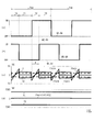
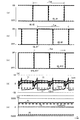
- FIG. 3 is a time chart showing changes in the driving state of each switch.
- FIG. 4 is a diagram showing a current flow path in the first period.
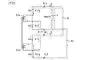
- FIG. 5 is a diagram showing a current flow path in the second period.
- FIG. 6 is a diagram showing a current flow path in the third period.
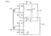
- FIG. 7 is a diagram showing a current flow path in the fourth period.
- FIG. 8 is a flowchart showing the processing procedure of the temperature rising mode control.
- FIG. 1 is an overall configuration diagram of an in-vehicle power supply system according to the first embodiment.
- FIG. 2 is a functional block diagram showing the processing of the control unit.
- FIG. 3 is a time chart showing changes in the driving state of each switch.
- FIG. 4 is a diagram showing a current flow path in the first period.
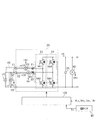
- FIG. 9 is a configuration diagram of the power supply system according to the second embodiment.
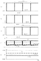
- FIG. 10 is a time chart showing the transition of the driving state and the like of each switch when the temperature rising mode control is performed.
- FIG. 11 is a time chart showing the transition of the drive state and the like of each switch when the temperature rise mode control is not performed.
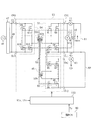
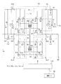
- FIG. 12 is a configuration diagram of the power supply system according to the third embodiment.
- FIG. 13 is a functional block diagram showing the processing of the control unit.
- FIG. 14 is a time chart showing changes in the driving state of each switch.
- FIG. 15 is a configuration diagram of the power supply system according to the fourth embodiment.
- FIG. 16 is a functional block diagram showing the processing of the control unit.
- FIG. 17 is a time chart showing changes in the driving state of each switch.
- FIG. 18 is a configuration diagram of the power supply system according to the fifth embodiment.
- FIG. 19 is a time chart showing changes in the driving state of each switch.
- FIG. 20 is a configuration diagram of the power supply system according to the sixth embodiment.
- FIG. 21 is a flowchart showing a processing procedure of temperature rise mode control.
- FIG. 22 is a configuration diagram of the power supply system according to the seventh embodiment.
- FIG. 23 is a flowchart showing a processing procedure of the temperature rising mode control according to the eighth embodiment.
- the power supply system of this embodiment is mounted on an electrified vehicle such as a plug-in hybrid vehicle (PHEV) or an electric vehicle (EV).
- PHEV plug-in hybrid vehicle
- EV electric vehicle
- the power supply system mounted on the vehicle includes a storage battery 10 (corresponding to a power storage unit), a DCDC converter 20, an inverter 30, and a rotary electric machine 40 as a running power source for the vehicle.
- the storage battery 10 is a rechargeable and dischargeable secondary battery, for example, a lithium ion storage battery or a nickel hydrogen storage battery.
- a DCDC converter 20 is connected to the storage battery 10.
- the armature winding of the rotary electric machine 40 is electrically connected to the DCDC converter 20 via an inverter 30.
- the DCDC converter 20 has a step-up function of boosting the DC voltage input from the storage battery 10 and outputting it to the inverter 30, and a step-down function of stepping down the DC voltage input from the inverter 30 and outputting it to the storage battery 10. ..
- the inverter 30 performs a power running operation that converts the DC power output from the DCDC converter 20 into AC power and supplies it to the armature winding of the rotary electric machine 40. As a result, the rotor of the rotary electric machine 40 is rotationally driven to rotate the drive wheels 41 of the vehicle. On the other hand, the inverter 30 performs a regenerative operation of converting the AC power generated by the rotary electric machine 40 into DC power and supplying it to the DCDC converter 20.
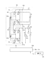
- the power supply system includes a power conversion circuit 50.
- the power conversion circuit 50 includes a first full bridge circuit 51 (corresponding to the first conversion circuit) and a second full bridge circuit 52 (corresponding to the second conversion circuit).
- the first full bridge circuit 51 includes first to fourth switches Q1 to Q4 (corresponding to the first conversion switch).
- the first to fourth switches Q1 to Q4 are N-channel MOSFETs.
- the first high potential side terminal CH1 of the power conversion circuit 50 is connected to the drains of the first switch Q1 and the third switch Q3.
- the drain of the second switch Q2 is connected to the source of the first switch Q1, and the drain of the fourth switch Q4 is connected to the source of the third switch Q3.
- the first low potential side terminal CL1 of the power conversion circuit 50 is connected to the sources of the second switch Q2 and the fourth switch Q4.
- the first full bridge circuit 51 is a circuit in which one of DC power and AC power is used as an input and the other is used as an output.
- the first high potential side terminal CH1 and the first low potential side terminal CL1 correspond to the first terminal.
- the second full bridge circuit 52 includes fifth to eighth switches Q5 to Q8 (corresponding to the second conversion switch).
- the fifth to eighth switches Q5 to Q8 are N-channel MOSFETs.
- the second high potential side terminal CH2 of the power conversion circuit 50 is connected to the drains of the fifth switch Q5 and the seventh switch Q7.
- the drain of the sixth switch Q6 is connected to the source of the fifth switch Q5, and the drain of the eighth switch Q8 is connected to the source of the seventh switch Q7.
- the second low potential side terminal CL2 of the power conversion circuit 50 is connected to the sources of the sixth switch Q6 and the eighth switch Q8.
- the second high potential side terminal CH2 and the second low potential side terminal CL2 correspond to the second terminal.
- the power conversion circuit 50 includes a transformer 53 having a first coil 53a and a second coil 53b.
- the source of the first switch Q1 and the drain of the second switch Q2 are connected to the first end of the first coil 53a, and the source of the third switch Q3 and the fourth switch Q4 are connected to the second end of the first coil 53a. Drain is connected.
- the source of the fifth switch Q5 and the drain of the sixth switch Q6 are connected to the first end of the second coil 53b, and the source of the seventh switch Q7 and the eighth switch Q8 are connected to the second end of the second coil 53b. Drain is connected.
- the first coil 53a and the second coil 53b are magnetically coupled to each other.
- an induced voltage is generated in the second coil 53b so that the potential of the first end becomes higher than that of the second end.
- an induced voltage is generated in the second coil 53b so that the potential of the second end becomes higher than that of the first end.
- the power conversion circuit 50 includes a high potential side electric path 61 and a low potential side electric path 62.
- the high potential side electric path 61 connects the first high potential side terminal CH1 and the second high potential side terminal CH2, and the low potential side electric path 62 connects the first low potential side terminal CL1 and the second low potential side terminal. It is connected to CL2.
- the positive electrode terminal of the storage battery 10 is connected to the high potential side electric path 61, and the negative electrode terminal of the storage battery 10 is connected to the low potential side electric path 62.
- the power supply system includes a heat transfer unit 45.
- the heat transfer unit 45 has the first to eighth switches Q1 to Q8, the transformer 53, and the storage battery 10 as heat exchange target elements, and is configured to be able to absorb the heat generated by the heat exchange target elements.
- the heat transfer unit 45 transfers the absorbed heat to the element to be heated, and raises the temperature of the element to be heated.
- the element to be heated is, for example, at least one of the rotary electric machine 40 and the storage battery 10.
- the heat transfer unit 45 includes, for example, a circulation path in which cooling water circulates between the heat exchange target element and the temperature rise target element, and raises the temperature of the temperature rise target element through the cooling water. May be good.
- a gas air
- the heat transfer unit 45 may be, for example, a constituent member such as a heat sink that comes into contact with the heat exchange target element and the temperature rise target element without using a cooling fluid.
- the power supply system includes a voltage sensor 70, a current sensor 80, and a temperature sensor 90.
- the voltage sensor 70 detects the voltage between the terminals of the storage battery 10, and the current sensor 80 detects the current flowing through the high potential side electric path 61.
- the temperature sensor 90 detects the temperature of the element to be heated. The detected values of the voltage sensor 70, the current sensor 80, and the temperature sensor 90 are input to the control unit 100 included in the power supply system.
- the control unit 100 controls the switches Q1 to Q8 of the DCDC converter 20, the inverter 30, and the power conversion circuit 50.
- the control unit 100 includes a command current setting unit 110.
- the command current setting unit 110 includes a command power limiting unit 111, a current calculation unit 112, and a minimum value selection unit 113.
- the command power limiting unit 111 limits the input command power P2 * by the upper limit limit value Plim based on the detection temperature Tr of the temperature sensor 90. In the present embodiment, when the command power P2 * is positive, the output power of the storage battery 10 is transmitted to the storage battery 10 via the first full bridge circuit 51, the transformer 53, the second full bridge circuit 52, and the respective electric paths 61 and 62. Control is performed to return again.
- the command power limiting unit 111 When the input command power P2 * exceeds the upper limit limit value Plim, the command power limiting unit 111 outputs the same value as the upper limit limit value Plim as the command power P2 *. On the other hand, when the input command power P2 * is equal to or less than the upper limit limit value Plim, the command power limiting unit 111 outputs the input command power P2 * as it is.
- the command power limiting unit 111 sets the upper limit limit value Plim larger as the detection temperature Tr is lower. That is, when the detection temperature Tr is low, the environmental temperature around the power supply system is low, so that it is considered that the cooling capacity of the heat exchange target element is sufficient. In this case, it is considered that the temperature of the power conversion circuit 50 and the like does not rise excessively even if the command power P2 * is increased.
- the current calculation unit 112 divides the command power P2 * output from the command power limiting unit 111 by the power supply voltage V1r, which is the detection voltage of the voltage sensor 70, so that the command current I2f flows to the second high potential side terminal CH2. Is calculated.
- the command current I2f indicates that a current flows from the high potential side electric path 61 toward the second high potential side terminal CH2, and when the sign is negative, the command current I2f is high from the second high potential side terminal CH2. It shows that the current flows in the direction toward the electric potential side electric path 61.
- the minimum value selection unit 113 selects the smaller of the command current I2f calculated by the current calculation unit 112 and the current limit value I2lim as the final command current Iref2.
- the current limit value I2lim is set to protect the power supply system from overcurrent.
- the upper limit value or the lower limit value of the command current Iref2 output from the minimum value selection unit 113 is limited by the limiter 114.
- the control unit 100 includes a current controller 120.
- the current controller 120 includes a current deviation calculation unit 121, a feedback control unit 122, and a limiter 123.
- the current deviation calculation unit 121 calculates the current deviation ⁇ I2 by subtracting the detection current I2r of the current sensor 80 from the command current Iref2 output from the limiter 114.
- the feedback control unit 122 calculates the command phase ⁇ as the operation amount for feedback controlling the calculated current deviation ⁇ I2 to 0. In the present embodiment, proportional integral control is used as this feedback control.
- the command phase ⁇ will be described later.
- the feedback control used in the feedback control unit 122 is not limited to the proportional integral control, and may be, for example, the proportional integral differential control.
- the upper limit value or the lower limit value of the command phase ⁇ calculated by the feedback control unit 122 is limited by the limiter 123, and is input to the PWM generation unit 130.
- the PWM generation unit 130 generates drive signals for the switches Q1 to Q8 based on the command phase ⁇ and outputs them to the gates of the switches Q1 to Q8.
- the driving modes of the switches Q1 to Q8 will be described with reference to FIG.
- FIG. 3A shows the transition of the driving state of the first to fourth switches Q1 to Q4
- FIG. 3B shows the transition of the driving state of the fifth to eighth switches Q5 to Q8.
- the first switch Q1 and the fourth switch Q4 are synchronized with the on switching timing and the off switching timing. Further, the second switch Q2 and the third switch Q3 are synchronized with each other when they are switched on and when they are switched off. The set of the first and fourth switches Q1 and Q4 and the set of the second and third switches Q2 and Q3 are turned on alternately.
- the fifth switch Q5 and the eighth switch Q8 are synchronized with the on switching timing and the off switching timing. Further, the sixth switch Q6 and the seventh switch Q7 are synchronized with the on switching timing and the off switching timing.
- the set of the fifth and eighth switches Q5 and Q8 and the set of the sixth and seventh switches Q6 and Q7 are turned on alternately.
- the 1 switching cycle Tsw of each switch Q1 to Q8 is the same as each other.
- the phase difference between the on-switching timing of the first and fourth switches Q1 and Q4 and the on-switching timing of the sixth and seventh switches Q6 and Q7 is defined as the command phase ⁇ .
- the command phase ⁇ becomes negative when the timing of switching the first and fourth switches Q1 and Q4 to ON is delayed with respect to the timing of switching the sixth and seventh switches Q6 and Q7 to ON. , It becomes positive when it is early.
- the first to fourth periods T1 to T4 appear in one switching cycle Tsw.
- the first period T1 the second, third, sixth, and seventh switches Q2, Q3, Q6, and Q7 are turned on, and the first, fourth, fifth, and eighth switches Q1, Q4, and Q5. This is the period during which Q8 is turned off.
- the second period T2 the first, fourth, sixth, and seventh switches Q1, Q4, Q6, and Q7 are turned on, and the second, third, fifth, and eighth switches Q2, Q3, and Q5. This is the period during which Q8 is turned off.
- the first, fourth, fifth, and eighth switches Q1, Q4, Q5, and Q8 are turned on, and the second, third, sixth, and seventh switches Q2, Q3, and Q6. This is the period during which Q7 is turned off.
- the second, third, fifth, and eighth switches Q2, Q3, Q5, and Q8 are turned on, and the first, fourth, sixth, and seventh switches Q1, Q4, and Q6. This is the period during which Q7 is turned off.
- FIG. 3C shows changes in the first current I1, the second current I2, and the battery current Ibatt, which is the current flowing through the storage battery 10.
- the first current I1 is a current flowing through the first high potential side terminal CH1
- the second current I2 is a current flowing through the second high potential side terminal CH2.
- the case where the first current I1 flows in the direction from the high potential side electric path 61 to the first high potential side terminal CH1 is positive
- the second current I2 is from the high potential side electric path 61 to the second high potential side terminal CH2.
- the case where the current flows in the direction toward is positive.
- the battery current Ibatt is positive when it flows in the direction from the negative electrode terminal to the positive electrode terminal of the storage battery 10.
- the time average value I1ave of the first current I1 and the time average value I2ave of the second current I2 are shown by broken lines.
- FIG. 3D shows the transition of the first power P1, the second power P2, and the battery power Pbatt.
- the first electric power P1 is a time average value of the electric power supplied from the storage battery 10 to the first full bridge circuit 51
- the second electric power P2 is the second electric power P2 from the second full bridge circuit 52 via the respective electric paths 61 and 62. It is the time average value of the electric power supplied to the storage battery 10.
- the battery power Pbatt is the total value of the first power P1 and the second power P2.
- the first current I1 becomes a positive constant value.
- a closed circuit including CL2 and the sixth switch Q6 is formed.
- the second current I2 becomes negative, and its absolute value becomes the same as the absolute value of the first current I1. Therefore, the battery current Ibatt becomes 0.
- FIG. 5 shows the current flow path in the latter half of the second period T2.
- the leakage inductance of the transformer 53 causes the current to flow to the first coil 53a in the first period T1.
- a current tries to flow in the first coil 53a in the same direction as the current flow direction. Since this current flows to the first high potential side terminal CH1 through the body diode of the first switch Q1, the first current I1 has a negative value. After that, the first current I1 gradually increases to a positive value.
- a current is applied to the closed circuit including the storage battery 10, the first high potential side terminal CH1, the first switch Q1, the first coil 53a, the fourth switch Q4, and the first low potential side terminal CL1. It flows.
- a closed circuit is formed.
- the second current I2 has the same value as the first current I1.
- the battery current Ibatt gradually increases from a negative value and then becomes a positive value.
- the first current I1 becomes a positive constant value.
- a closed circuit is formed.
- the second current I2 becomes negative, and its absolute value becomes the same as the absolute value of the first current I1. Therefore, the battery current Ibatt becomes 0.
- FIG. 7 shows the current flow path in the latter half of the fourth period T4.
- the storage battery 10 When the second and third switches Q2 and Q3 are switched on and the first and fourth switches Q1 and Q4 are switched off, the storage battery 10, the first high potential side terminal CH1, the third switch Q3, and the first coil A current flows through a closed circuit including 53a, the second switch Q2, and the first low potential side terminal CL1.
- the transition of the first current I1, the second current I2, and the battery current Ibatt in the fourth period T4 is the same as the transition in the second period T2.
- the battery power Pbatt is a positive value. This indicates that power loss occurs in the power conversion circuit 50, the storage battery 10, and the like during the first to fourth periods T1 to T4. This power loss mainly occurs in the storage battery 10, each switch Q1 to Q8, and the transformer 53. The generated heat is absorbed by the heat transfer unit 45 and used for raising the temperature of the element to be heated.
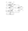
- FIG. 8 shows a procedure of processing executed by the control unit 100. This process is repeatedly executed, for example, at a predetermined control cycle.
- step S10 it is determined whether or not there is a temperature rise request. Specifically, for example, when it is determined that the environmental temperature is equal to or lower than a predetermined temperature, it may be determined that there is a request for temperature rise.
- the environmental temperature is a temperature at which it can be determined whether or not the temperature rise mode control should be performed, such as the detection temperature Tr of the temperature sensor 90, the temperature of the heat transfer unit 45, or the ambient temperature of the power supply system.
- step S10 If a negative determination is made in step S10, the process proceeds to step S11 and normal mode control is performed. In this case, in step S12, the command power P2 * is set to 0. Therefore, the driving of the switches Q5 to Q8 of the second full bridge circuit 52 is stopped.
- step S10 determines whether an affirmative judgment is made in step S10 or the process is a affirmative judgment.
- the process proceeds to step S13 and the temperature rise mode control is performed.
- step S14 the command power P2 * is set to a value smaller than 0. As a result, the amount of heat generated in the power conversion circuit 50 or the like increases as compared with the case where the normal mode control is performed.
- the control unit 100 performs temperature rise mode control when there is a request for temperature rise of the element to be heated.
- the amount of heat generated by the power conversion circuit 50 or the like increases as compared with the case where there is no request for temperature rise. Therefore, the temperature of the element to be heated can be raised by using the heat generated by the power conversion circuit 50 or the like. Therefore, according to the present embodiment, it is not necessary to newly equip the power supply system with a heat generating device for raising the temperature of the element to be heated. As a result, the power supply system can be miniaturized.
- the temperature rise mode control is performed using a power conversion circuit 50 other than the inverter 30 connected to the rotary electric machine 40 which is a running power source. Therefore, by implementing the temperature rise mode control, it is possible to prevent the occurrence of a situation in which torque is generated in the rotary electric machine 40 when the vehicle is stopped and the vehicle moves, or the torque fluctuates when the vehicle is running.
- the electric power circulates not in the direction from the storage battery 10 to the first full bridge circuit 51 but in the direction from the storage battery 10 to the second full bridge circuit 52 via the electric paths 61 and 62. It may be. This can be achieved by setting the command power P2 * to a positive value.
- the power conversion circuit 50 includes a third full bridge circuit 54 (corresponding to a third conversion circuit). Note that, in FIG. 9, the same components as those shown in FIG. 1 above are designated by the same reference numerals for convenience. Further, in FIG. 9, the illustration of the DCDC converter 20 and the like is omitted.
- the third full bridge circuit 54 includes 9th to 12th switches Q9 to Q12 (corresponding to 3rd conversion switch).
- the 9th to 12th switches Q9 to Q12 are N-channel MOSFETs.
- the third high potential side terminal CH3 of the power conversion circuit 50 is connected to the drains of the ninth switch Q9 and the eleventh switch Q11.
- the drain of the 10th switch Q10 is connected to the source of the 9th switch Q9, and the drain of the 12th switch Q12 is connected to the source of the 11th switch Q11.
- the third low potential side terminal CL3 of the power conversion circuit 50 is connected to the sources of the 10th switch Q10 and the 12th switch Q12.
- the third high potential side terminal CH3 and the third low potential side terminal CL3 correspond to the third terminal.
- the transformer 53 includes a third coil 53c.
- the source of the 9th switch Q9 and the drain of the 10th switch Q10 are connected to the first end of the third coil 53c, and the source of the 11th switch Q11 and the 12th switch Q12 are connected to the second end of the third coil 53c.
- the first coil 53a, the second coil 53b, and the third coil 53c to which the drains of the above are connected are magnetically coupled to each other.
- the heat transfer unit 45 further sets the 9th to 12th switches Q9 to Q12 as heat exchange target elements.
- the power supply system includes a capacitor 46 and a converter 47.
- the capacitor 46 connects the third high potential side terminal CH3 and the third low potential side terminal CL3.
- the converter 47 has a function of improving the power factor while converting the AC power supplied from the external power source 48 into the DC power.
- the output power of the external power supply 48 is supplied to the storage battery 10 via the converter 47, the third full bridge circuit 54 and the transformer 53, and at least one of the first full bridge circuit 51 and the second full bridge circuit 52. As a result, the storage battery 10 is charged.
- control unit 100 controls the 9th to 12th switches Q9 to Q12 on and off.
- the 9th switch Q9 and the 12th switch Q12 are synchronized with the on switching timing and the off switching timing. Further, the 10th switch Q10 and the 11th switch Q11 are synchronized with each other when they are switched on and when they are switched off.
- the set of the 9th and 12th switches Q9 and Q12 and the set of the 10th and 11th switches Q10 and Q11 are turned on alternately.
- the one switching cycle of the ninth to twelfth switches Q9 to Q12 is the same as the one switching cycle Tsw of the first to eighth switches Q1 to Q8.
- FIG. 10D shows the transitions of the first current I1, the second current I2, the battery current Ibatt, and the third current I3.
- the third current I3 is a current flowing through the third high potential side terminal CH3.
- the case where the third current I3 flows in the direction from the converter 47 toward the third high potential side terminal CH3 is positive.
- the time average value I3ave of the third current I3 is shown by a broken line.
- the third electric power P3 is a time average value of the charging electric power from the external power source 48 to the storage battery 10.
- the total power is a positive value in this embodiment. Therefore, the temperature rising mode control can be performed while charging the storage battery 10 from the external power source 48.
- FIG. 11 shows a case where the temperature rise mode control is not performed and only the storage battery 10 is charged from the external power source 48.
- the output power of the external power supply 48 is received by both the first full bridge circuit 51 and the second full bridge circuit 52 and supplied to the storage battery 10. Since the temperature rise mode control is not performed, only the loss due to charging is performed, and the total power is closer to 0 as compared with the case of FIG. 10 (e).
- the temperature rise mode control can be performed without being affected by the operation of charging the storage battery 10 from the external power supply 48 via the third full bridge circuit 54.
- the power conversion circuit 50 includes a fourth full bridge circuit 55 (corresponding to a fourth conversion circuit). Note that, in FIG. 12, the same configurations as those shown in FIG. 9 or the corresponding configurations are designated by the same reference numerals for convenience.
- the fourth full bridge circuit 55 includes 13th to 16th switches Q13 to Q16 (corresponding to the 4th conversion switch).
- the 13th to 16th switches Q13 to Q16 are N-channel MOSFETs.
- the fourth high potential side terminal CH4 of the power conversion circuit 50 is connected to the drains of the 13th switch Q13 and the 16th switch Q16.
- the drain of the 14th switch Q14 is connected to the source of the 13th switch Q13, and the drain of the 16th switch Q16 is connected to the source of the 15th switch Q15.
- the fourth low potential side terminal CL4 of the power conversion circuit 50 is connected to the sources of the 14th switch Q14 and the 16th switch Q16.
- the fourth high potential side terminal CH4 and the fourth low potential side terminal CL4 correspond to the fourth terminal.
- the power conversion circuit 50 includes a first transformer 56 and a second transformer 57.
- the first transformer 56 includes a first coil 56a and a second coil 56b.
- the source of the first switch Q1 and the drain of the second switch Q2 are connected to the first end of the first coil 56a, and the source of the third switch Q3 and the fourth switch Q4 are connected to the second end of the first coil 56a. Drain is connected.
- the source of the 9th switch Q9 and the drain of the 10th switch Q10 are connected to the first end of the second coil 56b, and the source of the 11th switch Q11 and the 12th switch Q12 are connected to the second end of the second coil 56b. Drain is connected.
- the first coil 56a and the second coil 56b are magnetically coupled to each other.
- an induced voltage is generated in the second coil 56b so that the potential of the first end becomes higher than that of the second end.
- the second transformer 57 includes a third coil 57a and a fourth coil 57b.
- the source of the fifth switch Q5 and the drain of the sixth switch Q6 are connected to the first end of the third coil 57a, and the source of the seventh switch Q7 and the eighth switch Q8 are connected to the second end of the third coil 57a. Drain is connected.
- the source of the 13th switch Q13 and the drain of the 14th switch Q14 are connected to the first end of the fourth coil 57b, and the source of the 15th switch Q15 and the 16th switch Q16 are connected to the second end of the fourth coil 57b. Drain is connected.
- the third coil 57a and the fourth coil 57b are magnetically coupled to each other.
- an induced voltage is generated in the fourth coil 57b so that the potential of the first end is higher than that of the second end.
- the high potential side electric path 61 is referred to as a first high potential side electric path
- the low potential side electric path 62 is referred to as a first low potential side electric path.
- the power conversion circuit 50 includes a second high potential side electric path 63 and a second low potential side electric path 64.
- the second high potential side electric path 63 connects the third high potential side terminal CH3 and the fourth high potential side terminal CH4, and the second low potential side electric path 64 connects the third low potential side terminal CL3 and the fourth. It is connected to the low potential side terminal CL4.
- the second high potential side electric path 63 and the second low potential side electric path 64 are connected by a capacitor 46.
- the first high potential side electric path 61 and the first low potential side electric path 62 correspond to the first electric path
- the second high potential side electric path 63 and the second low potential side electric path 64 Corresponds to the second electrical path.
- the heat transfer unit 45 further sets the 13th to 16th switches Q13 to Q16, the first transformer 56, and the second transformer 57 as heat exchange target elements.
- the voltage sensor 70 is referred to as the first voltage sensor 70
- the current sensor 80 is referred to as the first current sensor 80.
- the power supply system includes a second voltage sensor 71, a second current sensor 81, and a third current sensor 82.
- the second voltage sensor 71 detects the voltage between the terminals of the capacitor 46.
- the second current sensor 81 detects the current flowing through the first high potential side terminal CH1
- the third current sensor 82 detects the current flowing through the second high potential side electric path 63.
- the detected values of the second voltage sensor 71, the second current sensor 81, and the third current sensor 82 are input to the control unit 100.
- the control unit 100 calculates the first command phase ⁇ 1, the second command phase ⁇ 2, and the fourth command phase ⁇ 4.
- Each command phase ⁇ 1, ⁇ 2, ⁇ 4 will be described with reference to FIG. 14 (a) to 14 (c) correspond to the above 10 (a) to 10 (c), and FIG. 14 (d) shows the transition of the driving state of the 13th to 16th switches Q13 to Q16.
- the 13th switch Q13 and the 16th switch Q16 are synchronized with the on switching timing and the off switching timing. Further, the 14th switch Q14 and the 15th switch Q15 are synchronized with the on switching timing and the off switching timing.
- the set of the 13th and 16th switches Q13 and Q16 and the set of the 14th and 15th switches Q14 and Q15 are turned on alternately.
- the one switching period Tsw of each switch Q1 to Q16 is the same as each other.
- the first command phase ⁇ 1 is a command value of the phase difference between the on switching timing of the ninth and twelfth switches Q9 and Q12 and the on switching timing of the first and fourth switches Q1 and Q4.
- the first command phase ⁇ 1 becomes negative when the switching timing of the 9th and 12th switches Q9 and Q12 to ON is delayed with respect to the ON switching timing of the 1st and 4th switches Q1 and Q4, and is accelerated. Becomes positive.
- the second command phase ⁇ 2 is a command value of the phase difference between the timing of switching the 9th and 12th switches Q9 and Q12 to ON and the timing of switching the 5th and 8th switches Q5 and Q8 to ON.
- the fourth command phase ⁇ 4 is a command value of the phase difference between the timing of switching the 9th and 12th switches Q9 and Q12 to ON and the timing of switching the 13th and 16th switches Q13 and Q16 to ON.
- the definitions of the codes of the second and fourth command phases ⁇ 2 and ⁇ 4 are the same as the definitions of the codes of the first command phase ⁇ 1.
- control unit 100 includes a first command current setting unit 140 and a first current controller 150 as a configuration for calculating the first command phase ⁇ 1.
- the first command current setting unit 140 includes a first current calculation unit 142 and a first minimum value selection unit 143.
- the first current calculation unit 142 divides the input first command power P1 * by the first power supply voltage V1r, which is the detection voltage of the first voltage sensor 70, to cause the first high potential side terminal CH1 to flow. 1
- the command current I1f is calculated.
- the first command power P1 * is a command value of power transmitted between the first full bridge circuit 51 and the first transformer 56. When the first command power P1 * is positive, power is transmitted from the first full bridge circuit 51 to the first transformer 56.
- the first minimum value selection unit 143 sets the final first one of the first command current I1f calculated by the first current calculation unit 142 and the first current limit value I1lim for overcurrent protection. Select as the command current Iref1.
- the upper limit value or the lower limit value of the first command current Iref1 output from the first minimum value selection unit 143 is limited by the limiter 144.
- the first current controller 150 includes a first current deviation calculation unit 151, a first feedback control unit 152, and a first limiter 153.
- the first current deviation calculation unit 151 calculates the first current deviation ⁇ I1 by subtracting the detection current I1r of the second current sensor 81 from the first command current Iref1 output from the limiter 144.
- the first feedback control unit 152 calculates the first command phase ⁇ 1 as an operation amount for feedback-controlling the calculated first current deviation ⁇ I1 to 0.
- the calculated first command phase ⁇ 1 is input to the PWM generation unit 200 after the upper limit value or the lower limit value is limited by the first limiter 153.
- the control unit 100 includes a second command current setting unit 160 and a second current controller 170 as a configuration for calculating the second command phase ⁇ 2.
- the second command current setting unit 160 includes a second current calculation unit 162 and a second minimum value selection unit 163.
- the second current calculation unit 162 divides the input second command power P2 * by the first power supply voltage V1r detected by the first voltage sensor 70, thereby causing the second high potential side terminal CH2 to flow.
- the command current I2f is calculated.
- the second command power P2 * is a command value of the power transmitted between the second full bridge circuit 52 and the second transformer 57. When the second command power P2 * is negative, power is transmitted from the second transformer 57 to the second full bridge circuit 52.
- the smaller of the second command current I2f calculated by the second current calculation unit 162 and the second current limit value I2lim for overcurrent protection is the final second. Select as the command current Iref2.
- the upper limit value or the lower limit value of the second command current Iref2 output from the second minimum value selection unit 163 is limited by the limiter 164.
- the second current controller 170 includes a second current deviation calculation unit 171, a second feedback control unit 172, and a second limiter 173.
- the second current deviation calculation unit 171 calculates the second current deviation ⁇ I2 by subtracting the detection current I2r of the first current sensor 80 from the second command current Iref2 output from the limiter 164.
- the second feedback control unit 172 calculates the second command phase ⁇ 2 as an operation amount for feedback-controlling the calculated second current deviation ⁇ I2 to 0.
- the calculated second command phase ⁇ 2 is input to the PWM generation unit 200 after the upper limit value or the lower limit value is limited by the second limiter 173.
- the control unit 100 includes a fourth command current setting unit 180 and a fourth current controller 190 as a configuration for calculating the fourth command phase ⁇ 4.
- the fourth command current setting unit 180 includes a fourth current calculation unit 182 and a fourth minimum value selection unit 183.
- the fourth current calculation unit 182 divides the input fourth command power P4 * by the third power supply voltage V3r detected by the second voltage sensor 71, thereby causing the fourth high potential side terminal CH4 to flow.
- the command current I4f is calculated.
- the fourth command power P4 * is a command value of the power transmitted between the fourth full bridge circuit 55 and the second transformer 57. When the fourth command power P4 * is positive, power is transmitted from the fourth full bridge circuit 55 to the second transformer 57.
- the fourth minimum value selection unit 183 the smaller of the fourth command current I4f calculated by the fourth current calculation unit 182 and the fourth current limit value I4lim for overcurrent protection is the final fourth. Select as the command current Iref4.
- the upper limit value or the lower limit value of the fourth command current Iref2 output from the fourth minimum value selection unit 183 is limited by the limiter 184.
- the fourth current controller 190 includes a fourth current deviation calculation unit 191 and a fourth feedback control unit 192 and a fourth limiter 193.
- the fourth current deviation calculation unit 191 calculates the fourth current deviation ⁇ I4 by subtracting the detection current I4r of the third current sensor 82 from the fourth command current Iref4 output from the limiter 184.
- the fourth feedback control unit 192 calculates the fourth command phase ⁇ 4 as an operation amount for feedback-controlling the calculated fourth current deviation ⁇ I4 to 0.
- the calculated fourth command phase ⁇ 4 is input to the PWM generation unit 200 after the upper limit value or the lower limit value is limited by the fourth limiter 193.
- the PWM generation unit 200 generates drive signals for the switches Q1 to Q16 so as to realize the first command phase ⁇ 1, the second command phase ⁇ 2, and the fourth command phase ⁇ 4 for the gates of the switches Q1 to Q16. And output.
- the output power of the storage battery 10 is the first full bridge circuit 51, the first transformer 56, the third full bridge circuit 54, each electric path 63, 64, the fourth full bridge circuit 55, the second transformer 57,
- a temperature rise mode control for turning on / off each of the switches Q1 to Q16 is performed so as to circulate through the path including the second full bridge circuit 52 and the electric paths 61 and 62.
- the absolute values of the first command power P1 *, the second command power P2 *, and the fourth command power P4 * are set to the same values.
- the first command power P1 * and the fourth command power P4 * are set to positive values
- the second command power P2 * is set to a negative value.
- FIG. 14E shows the transition of the first to fourth currents I1 to I4.
- the fourth current I4 is a current flowing through the fourth high potential side terminal CH4.
- the case where the fourth current I4 flows in the direction from the second high potential side electric path 63 toward the fourth high potential side terminal CH4 is positive.
- the first electric power P1 is the time average value of the electric power transmitted between the first full bridge circuit 51 and the first transformer 56
- the second electric power P2 is the second full bridge circuit 52 and the second transformer 57. It is the time average value of the electric power transmitted between the two.
- the third power P3 is the time average value of the power transmitted between the third full bridge circuit 54 and the first transformer 56
- the fourth power P4 is the fourth full bridge circuit 55 and the second transformer 57. It is the time average value of the electric power transmitted between the two. Since the total power is larger than 0, a loss is generated in the power conversion circuit 50 by performing the temperature rise mode control, and heat is generated by the loss. The generated heat is absorbed by the heat transfer unit 45.
- the full bridge circuit in which the power is input may be composed of a bridge circuit such as a diode.
- the positive electrode terminal of the storage battery 10 is connected to the first terminal C1 and the second terminal C2 of the DCDC converter 20, and the negative electrode terminal of the storage battery 10 is connected to the third terminal C3.
- the DCDC converter 20 includes a first reactor 21, a second reactor 22, a first bridge circuit 23, a second bridge circuit 24, and a capacitor 25.
- the first bridge circuit 23 includes a series connection of the first upper arm switch QA1 and the first lower arm switch QA2.
- the second bridge circuit 24 includes a series connection of the second upper arm switch QA3 and the second lower arm switch QA4.
- each switch QA1 to QA4 is an IGBT.
- the first terminal C1 is connected to the first end of the first reactor 21, and the emitter of the first upper arm switch QA1 and the collector of the first lower arm switch QA2 are connected to the second end of the first reactor 21.
- the second terminal C2 is connected to the first end of the second reactor 22, and the emitter of the second upper arm switch QA3 and the collector of the second lower arm switch QA4 are connected to the second end of the second reactor 22. ing.
- the first end of the capacitor 25 is connected to the collectors of the first upper arm switch QA1 and the second upper arm switch QA3.
- the second end of the capacitor 25 and the third terminal C3 are connected to the emitters of the first lower arm switch QA2 and the second lower arm switch QA4.
- the heat transfer unit 45 further sets the first reactor 21, the second reactor 22, and the switches QA1 to QA4 as heat exchange target elements.
- the power supply system includes an input side voltage sensor 91, an output side voltage sensor 92, a first reactor current sensor 93, and a second reactor current sensor 94.
- the input side voltage sensor 91 detects the potential difference between the first and second terminals C1 and C2 with respect to the third terminal C3.
- the output side voltage sensor 92 detects the voltage between the terminals of the capacitor 25.
- the first reactor current sensor 93 detects the current flowing through the first reactor 21, and the second reactor current sensor 94 detects the current flowing through the second reactor 22.
- the current IA flowing in the direction from the first end side to the second end side in the first reactor 21 is positive, and in the second reactor 22 in the direction from the first end side to the second end side. Let the flowing current IB be positive.
- the detected values of the input side voltage sensor 91, the output side voltage sensor 92, the first reactor current sensor 93, and the second reactor current sensor 94 are input to the control unit 100.
- the control unit 100 includes a first command current setting unit 210 and a first current controller 220.
- the first command current setting unit 210 includes a first current calculation unit 212 and a first minimum value selection unit 213.
- the first current calculation unit 212 calculates the first command current IAf to be passed through the first reactor 21 by dividing the input first command power PA * by the detection voltage VLr of the input side voltage sensor 91.
- the first command power PA * is a command value of power transmitted between the first terminal C1 and the first bridge circuit 23. When the first command power PA * is positive, power is transmitted from the first terminal C1 to the first bridge circuit 23.
- the detection voltage V1r of the voltage sensor 70 may be used instead of the detection voltage VLr of the input side voltage sensor 91.
- the first minimum value selection unit 213 is the final first one of the first command current IAf calculated by the first current calculation unit 212 and the first current limit value IAlim for overcurrent protection, whichever is smaller. Select as the command current IrefA.
- the upper limit value or the lower limit value of the first command current IrefA output from the first minimum value selection unit 213 is limited by the limiter 214.
- the first current controller 220 includes a first current deviation calculation unit 221, a first feedback control unit 222, a first limiter 223, a first addition unit 224, and a first duty calculation unit 225.
- the first current deviation calculation unit 221 calculates the first current deviation ⁇ IA by subtracting the detection current IAr of the first reactor current sensor 93 from the first command current IrefA output from the limiter 214.
- the first feedback control unit 222 calculates the first voltage V1 as an operation amount for feedback-controlling the calculated first current deviation ⁇ IA to 0.
- the calculated first voltage V1 has an upper limit value or a lower limit value limited by the first limiter 223 and is input to the first addition unit 224.
- the first addition unit 224 adds the detection voltage VLr of the input side voltage sensor 91 to the first voltage V1 output from the first limiter 223.
- the first duty calculation unit 225 calculates the first duty duty 1 by dividing the "V1 + VLr" calculated by the first addition unit 224 by the detection voltage VHr of the output side voltage sensor 92.
- the PWM generator 250 generates drive signals for the first upper and lower arm switches QA1 and QA2 based on the magnitude comparison between the first duty Duty1 and the carrier signal Sg (triangle wave signal), and generates the drive signals for the first upper and lower arm switches QA1 and QA2. Output to the gates of QA1 and QA2.
- the first upper arm switch QA1 and the first lower arm switch QA2 are turned on alternately.
- the control unit 100 includes a second command current setting unit 230 and a second current controller 240.
- the second command current setting unit 230 includes a second current calculation unit 232 and a second minimum value selection unit 233.
- the second current calculation unit 232 calculates the second command current IBf to be passed through the second reactor 22 by dividing the input second command power PB * by the detection voltage VLr of the input side voltage sensor 91.
- the second command power PB * is a command value of the power transmitted between the second terminal C2 and the second bridge circuit 24. When the second command power PB * is positive, power is transmitted from the second terminal C2 to the second bridge circuit 24.
- the second minimum value selection unit 233 decides which of the second command current IBf calculated by the second current calculation unit 232 and the second current limit value IBlim for overcurrent protection is the final second. Select as the command current IrefB.
- the upper limit value or the lower limit value of the second command current IrefB output from the second minimum value selection unit 233 is limited by the limiter 234.
- the second current controller 240 includes a second current deviation calculation unit 241, a second feedback control unit 242, a second limiter 243, a second addition unit 244, and a second duty calculation unit 245.
- the second current deviation calculation unit 241 calculates the second current deviation ⁇ IB by subtracting the detection current IBr of the second reactor current sensor 94 from the second command current IrefB output from the limiter 234.
- the second feedback control unit 242 calculates the second voltage V2 as an operation amount for feedback-controlling the calculated second current deviation ⁇ IB to 0.
- the calculated second voltage V2 is input to the second addition unit 244 after the upper limit value or the lower limit value is limited by the second limiter 243.
- the second addition unit 244 adds the detection voltage VLr of the input side voltage sensor 91 to the second voltage V2 output from the second limiter 243.
- the second duty calculation unit 245 calculates the second duty duty 2 by dividing the "V2 + VLr" calculated by the second addition unit 244 by the detection voltage VHr of the output side voltage sensor 92.
- the PWM generator 250 generates drive signals for the second upper and lower arm switches QA3 and QA4 based on the magnitude comparison between the second duty Duty 2 and the carrier signal Sg, and generates drive signals for the second upper and lower arm switches QA3 and QA4. Output to the gate.
- the second upper arm switch QA3 and the second lower arm switch QA4 are alternately turned on.
- one of the first command power PA * and the second command power PB * is set to a positive value, and the other is set to a negative value. Further, the absolute values of the first command power PA * and the second command power PB * are set to the same value. As a result, the output power of the storage battery 10 circulates in the path including the first reactor 21, the first upper arm switch QA1, the second upper arm switch QA3, and the second reactor 22.
- FIG. 17A shows the transition of the driving state of the first upper and lower arm switches QA1 and QA2
- FIG. 17B shows the transition of the driving state of the second upper and lower arm switches QA3 and QA4.
- FIG. 17C shows the transition of the first and second duty Duty 1, Duty 2 and the carrier signal Sg.
- FIG. 17D shows changes in the currents IA and IB flowing through the first and second reactors 21 and 22, the current IL flowing from the storage battery 10 to the DCDC converter 20, and the current IH output from the DCDC converter 20.
- FIG. 17E shows the transition of the time average values IAave, IBave, ILave, and IHave of the respective currents IA, IB, IL, and IH.
- the first power PA is the time average value of the power transmitted between the first terminal C1 and the first bridge circuit 23
- the second power PB is between the second terminal C2 and the second bridge circuit 24. It is the time average value of the electric power transmitted in.
- PH shown in FIG. 17 (f) is the amount of loss generated by the temperature rise mode control. With this loss, the heat absorbed by the heat transfer unit 45 can be generated, and the temperature of the element to be heated can be raised.
- the power conversion circuit 50 includes one transformer 58 instead of two transformers. Note that, in FIG. 18, the same configurations as those shown in FIG. 12 or the corresponding configurations are designated by the same reference numerals for convenience.
- the transformer 58 includes first to fourth coils 58a to 58d.
- the source of the first switch Q1 and the drain of the second switch Q2 are connected to the first end of the first coil 58a, and the source of the third switch Q3 and the fourth switch Q4 are connected to the second end of the first coil 58a. Drain is connected.
- the source of the 9th switch Q9 and the drain of the 10th switch Q10 are connected to the first end of the second coil 58b, and the source of the 11th switch Q11 and the 12th switch Q12 are connected to the second end of the second coil 58b. Drain is connected.
- the source of the 13th switch Q13 and the drain of the 14th switch Q14 are connected to the first end of the third coil 58c, and the source of the 15th switch Q15 and the 16th switch Q16 are connected to the second end of the third coil 58c. Drain is connected.
- the source of the fifth switch Q5 and the drain of the sixth switch Q6 are connected to the first end of the fourth coil 58d, and the source of the seventh switch Q7 and the eighth switch Q8 are connected to the second end of the fourth coil 58d. Drain is connected.
- the first to fourth coils 58a to 58d are magnetically coupled to each other.
- the second to fourth coils 58b to 58d have an induced voltage such that the potential of the first end is higher than that of the second end. appear.
- the functional block diagram of the temperature rise mode control of the control unit 100 is the same as that shown in FIG.
- the temperature rise mode control when it is desired to increase the amount of heat generated by the temperature rise mode control to a predetermined amount or more, the above-mentioned control is performed.
- the temperature rise mode control described in the first embodiment when it is desired to generate less than a predetermined amount of heat, for example, the temperature rise mode control described in the first embodiment can be carried out. Therefore, according to the present embodiment, the degree of freedom in the amount of heat generated can be increased.
- the second storage battery 11 is a rechargeable and dischargeable secondary battery, for example, a lithium ion storage battery or a nickel hydrogen storage battery.
- the positive electrode terminal of the second storage battery 11 is connected to the second high potential side terminal CH2, and the negative electrode terminal of the second storage battery 11 is connected to the second low potential side terminal CL2.
- the power supply system is equipped with a voltage sensor 72.
- the voltage sensor 72 detects the voltage between the terminals of the second storage battery 11. The detected value of the voltage sensor 72 is input to the control unit 100.
- FIG. 21 shows a flowchart of the temperature rising mode control carried out by the control unit 100. This process is repeatedly executed, for example, at a predetermined control cycle.
- step S20 the command power P2 * is set to a positive value.
- the command power P2 * is a command value of power transmitted between the first full bridge circuit 51 and the second full bridge circuit 52 via the transformer 53.
- the command power P2 * is positive, power is transmitted from the first full bridge circuit 51 to the second full bridge circuit 52 via the transformer 53.
- the switches Q1 to Q8 are controlled on and off so that the product of the detection voltage V2r of the voltage sensor 72 and the detection current I2r of the current sensor 80 follows the command power P2 *.
- step S21 it is determined whether or not a predetermined time has elapsed since the command power P2 * was switched to a positive value. If it is determined in step S21 that the predetermined time has elapsed, the process proceeds to step S22, and the command power P2 * is switched to a negative value.
- the absolute value of the command power P2 * set in step S22 and the absolute value of the command power P2 * set in step S20 are the same value.
- step S23 it is determined whether or not a predetermined time has elapsed since the command power P2 * was switched to a negative value. If it is determined in step S23 that the predetermined time has elapsed, the process proceeds to step S20, and the command power P2 * is switched to a positive value. Then, the switches Q1 to Q8 are on / off controlled so that the multiplied value of the detection voltage V2r of the voltage sensor 72 and the detection current I2r of the current sensor 80 follows the command power P2 *.
- the switches Q1 to Q8 are on / off controlled so that the charging of the first storage battery 10 and the charging and the charging of the second storage battery 11 are alternately performed. This makes it possible to control the amount of heat generated.
- ⁇ Modified example of the sixth embodiment> -Instead of the configuration in which the sign of the command power P2 * is switched each time a predetermined time elapses, for example, the potential difference of the first high potential side terminal CH1 with respect to the first low potential side terminal CL1 or the second with respect to the second high potential side terminal CH2. 2.
- the code may be switched based on the potential difference of the low potential side terminal CL2, or the code may be switched according to the charging degree (for example, SOC) of each of the storage batteries 10 and 11.
- the absolute value of the command power P2 * set in step S20 of FIG. 21 and the absolute value of the command power P2 * set in step S22 may be different.
- the second storage battery 11 is charged by the output power of the first storage battery 10. .
- the absolute value of the command power P2 * set in step S20 is made smaller than the absolute value of the command power P2 * set in step S22, the first storage battery 10 is charged by the output power of the second storage battery 11. Will be done. According to the configuration described above, it is possible to charge one of the first storage battery 10 and the second storage battery 11 to the other while performing the temperature rise mode control.
- an energy buffer element such as a capacitor, an external power source capable of bidirectional power transfer, or the like may be used.
- the seventh embodiment will be described with reference to the drawings, focusing on the differences from the second embodiment.
- the power supply system includes a heat generating device 300.
- the same components as those shown in FIGS. 9 and 12 are designated by the same reference numerals for convenience.
- the heat generating device 300 includes a resistor 301 and a capacitor 302.
- a third high potential side terminal CH3 is connected to the first end of each of the resistor 301 and the capacitor 302, and a third low potential side terminal CL3 is connected to the second end.
- the heat generating device 300 controls the amount of heat generated according to the environmental temperature, and transfers the generated heat to the heat transfer unit 45.
- the third full bridge circuit 54 is used to supply power to the heat generating device 300. This makes it possible to control the energization of the heat generating device 300 without adding new parts.
- the heat generated by the heat generating device 300 can also be transferred to the heat transfer unit 45.
- the heat transfer unit 45 if the temperature difference between the heat exchange target element such as each switch Q1 to Q12 and the heat transfer unit 45 is small, the amount of heat transferred from the heat exchange target element to the heat transfer unit 45 becomes small. Even in this case, according to the heat generating device 300, sufficient heat can be transferred to the heat transfer unit 45 without being affected by the temperature difference.
- the eighth embodiment when there is a temperature rise request, the gate voltage when each of the switches Q1 to Q8 is turned on is lowered to make the half-on state as compared with the case where there is no temperature rise request.
- FIG. 23 shows a flowchart of the temperature rising mode control carried out by the control unit 100.
- the same processing as that shown in FIG. 8 is designated by the same reference numerals for convenience.
- step S13 the process proceeds to step S15, and when the switches are turned on in the switches Q1 to Q8, the half-on state is set instead of the full-on state.
- the half-on state is a state in which the gate voltage when the switch is turned on is set to the voltage for driving the switch in the saturation region.
- the saturation region is a region in which the drain current is substantially constant regardless of the magnitude of the drain-source voltage in the output characteristics in which the drain-source voltage and the drain current of the switch are related.
- the on-resistance of the switch turned on in the temperature rise mode control can be increased as compared with the on-resistance in the fully-on state. Therefore, the amount of heat generated by the temperature rise mode control can be suitably increased.
- the power storage unit is not limited to a storage battery, but may be, for example, a capacitor.
- the controls and methods thereof described in the present disclosure are provided by a dedicated computer provided by configuring a processor and memory programmed to perform one or more functions embodied by a computer program. It may be realized. Alternatively, the controls and methods thereof described in the present disclosure may be implemented by a dedicated computer provided by configuring the processor with one or more dedicated hardware logic circuits. Alternatively, the control unit and method thereof described in the present disclosure may be a combination of a processor and memory programmed to perform one or more functions and a processor composed of one or more hardware logic circuits. It may be realized by one or more dedicated computers configured. Further, the computer program may be stored in a computer-readable non-transitional tangible recording medium as an instruction executed by the computer.
Landscapes
- Engineering & Computer Science (AREA)
- Power Engineering (AREA)
- Manufacturing & Machinery (AREA)
- Chemical & Material Sciences (AREA)
- Chemical Kinetics & Catalysis (AREA)
- Electrochemistry (AREA)
- General Chemical & Material Sciences (AREA)
- Mechanical Engineering (AREA)
- Transportation (AREA)
- Life Sciences & Earth Sciences (AREA)
- Sustainable Development (AREA)
- Sustainable Energy (AREA)
- Automation & Control Theory (AREA)
- Electromagnetism (AREA)
- Physics & Mathematics (AREA)
- Dc-Dc Converters (AREA)
- Electric Propulsion And Braking For Vehicles (AREA)
- Secondary Cells (AREA)
- Charge And Discharge Circuits For Batteries Or The Like (AREA)
- Inverter Devices (AREA)
Priority Applications (3)
| Application Number | Priority Date | Filing Date | Title |
|---|---|---|---|
| DE112020003260.4T DE112020003260T5 (de) | 2019-07-09 | 2020-07-07 | Leistungsversorgungssystem |
| CN202080049453.7A CN114097170B (zh) | 2019-07-09 | 2020-07-07 | 电源系统 |
| US17/570,057 US12036893B2 (en) | 2019-07-09 | 2022-01-06 | Power supply system |
Applications Claiming Priority (2)
| Application Number | Priority Date | Filing Date | Title |
|---|---|---|---|
| JP2019127581A JP7057767B2 (ja) | 2019-07-09 | 2019-07-09 | 電源システム |
| JP2019-127581 | 2019-07-09 |
Related Child Applications (1)
| Application Number | Title | Priority Date | Filing Date |
|---|---|---|---|
| US17/570,057 Continuation US12036893B2 (en) | 2019-07-09 | 2022-01-06 | Power supply system |
Publications (1)
| Publication Number | Publication Date |
|---|---|
| WO2021006275A1 true WO2021006275A1 (ja) | 2021-01-14 |
Family
ID=74115086
Family Applications (1)
| Application Number | Title | Priority Date | Filing Date |
|---|---|---|---|
| PCT/JP2020/026578 Ceased WO2021006275A1 (ja) | 2019-07-09 | 2020-07-07 | 電源システム |
Country Status (5)
| Country | Link |
|---|---|
| US (1) | US12036893B2 (https=) |
| JP (1) | JP7057767B2 (https=) |
| CN (1) | CN114097170B (https=) |
| DE (1) | DE112020003260T5 (https=) |
| WO (1) | WO2021006275A1 (https=) |
Families Citing this family (5)
| Publication number | Priority date | Publication date | Assignee | Title |
|---|---|---|---|---|
| JP7580322B2 (ja) * | 2021-03-30 | 2024-11-11 | 本田技研工業株式会社 | 昇温装置、昇温プログラム及び昇温方法 |
| WO2023029047A1 (zh) * | 2021-09-06 | 2023-03-09 | 宁德时代新能源科技股份有限公司 | 电池加热装置及其控制方法、控制电路和动力装置 |
| JP7522138B2 (ja) | 2021-08-05 | 2024-07-24 | 寧徳時代新能源科技股▲分▼有限公司 | 動力電池加熱システム、その制御方法及び制御回路 |
| JP7821279B2 (ja) * | 2022-06-27 | 2026-02-26 | 株式会社Soken | インバータ制御装置、プログラム、制御方法 |
| JP7301208B1 (ja) | 2022-12-05 | 2023-06-30 | 正一 田中 | バッテリ用交流電流供給回路 |
Citations (5)
| Publication number | Priority date | Publication date | Assignee | Title |
|---|---|---|---|---|
| JP2013187919A (ja) * | 2012-03-05 | 2013-09-19 | Nippon Soken Inc | 電力変換装置 |
| JP2014026814A (ja) * | 2012-07-26 | 2014-02-06 | Denso Corp | 電源温度調整装置 |
| JP2015220949A (ja) * | 2014-05-21 | 2015-12-07 | トヨタ自動車株式会社 | 電気自動車 |
| JP2016077076A (ja) * | 2014-10-06 | 2016-05-12 | トヨタ自動車株式会社 | モータ制御装置、及びモータ制御方法 |
| JP2016146252A (ja) * | 2015-02-06 | 2016-08-12 | 富士重工業株式会社 | 車載電池温調システム |
Family Cites Families (9)
| Publication number | Priority date | Publication date | Assignee | Title |
|---|---|---|---|---|
| JP3451141B2 (ja) | 1994-11-14 | 2003-09-29 | 本田技研工業株式会社 | バッテリ温度調節装置 |
| JP2009298190A (ja) * | 2008-06-10 | 2009-12-24 | Toyota Motor Corp | 蓄電手段の暖機装置 |
| JP2010119282A (ja) * | 2008-10-17 | 2010-05-27 | Denso Corp | 熱マネージメントシステム |
| FR2969050B1 (fr) * | 2010-12-21 | 2014-10-17 | Renault Sa | Procede et systeme de regulation de la temperature d'une batterie d'alimentation d'un vehicule a traction electrique et vehicule equipe d'un tel systeme |
| JP6252186B2 (ja) * | 2014-01-15 | 2017-12-27 | 株式会社デンソー | 車両用熱管理システム |
| US20160023532A1 (en) * | 2014-07-25 | 2016-01-28 | Atieva, Inc. | EV Integrated Temperature Control System |
| US10220722B2 (en) * | 2016-08-22 | 2019-03-05 | Ford Global Technologies, Llc | Operation of combined cooling circuit for power electronics and battery |
| JP7151410B2 (ja) | 2018-01-24 | 2022-10-12 | 東洋紡株式会社 | 透明性、耐薬品性に優れるホットメルト接着剤 |
| CN108470964A (zh) * | 2018-06-04 | 2018-08-31 | 常熟理工学院 | 一种新能源汽车动力电池热管理装置及其管理方法 |
-
2019
- 2019-07-09 JP JP2019127581A patent/JP7057767B2/ja active Active
-
2020
- 2020-07-07 WO PCT/JP2020/026578 patent/WO2021006275A1/ja not_active Ceased
- 2020-07-07 CN CN202080049453.7A patent/CN114097170B/zh active Active
- 2020-07-07 DE DE112020003260.4T patent/DE112020003260T5/de active Pending
-
2022
- 2022-01-06 US US17/570,057 patent/US12036893B2/en active Active
Patent Citations (5)
| Publication number | Priority date | Publication date | Assignee | Title |
|---|---|---|---|---|
| JP2013187919A (ja) * | 2012-03-05 | 2013-09-19 | Nippon Soken Inc | 電力変換装置 |
| JP2014026814A (ja) * | 2012-07-26 | 2014-02-06 | Denso Corp | 電源温度調整装置 |
| JP2015220949A (ja) * | 2014-05-21 | 2015-12-07 | トヨタ自動車株式会社 | 電気自動車 |
| JP2016077076A (ja) * | 2014-10-06 | 2016-05-12 | トヨタ自動車株式会社 | モータ制御装置、及びモータ制御方法 |
| JP2016146252A (ja) * | 2015-02-06 | 2016-08-12 | 富士重工業株式会社 | 車載電池温調システム |
Also Published As
| Publication number | Publication date |
|---|---|
| US20220131401A1 (en) | 2022-04-28 |
| JP7057767B2 (ja) | 2022-04-20 |
| DE112020003260T5 (de) | 2022-03-24 |
| CN114097170A (zh) | 2022-02-25 |
| JP2021012853A (ja) | 2021-02-04 |
| CN114097170B (zh) | 2024-01-12 |
| US12036893B2 (en) | 2024-07-16 |
Similar Documents
| Publication | Publication Date | Title |
|---|---|---|
| JP7057767B2 (ja) | 電源システム | |
| US20220286057A1 (en) | Energy conversion system, energy conversion method, and power system | |
| Zhang et al. | A common ground switched-quasi-$ Z $-source bidirectional DC–DC converter with wide-voltage-gain range for EVs with hybrid energy sources | |
| US10236776B2 (en) | Inter-supply bidirectional DC-DC converter of a non-insulation type | |
| CN108696107B (zh) | 单电源供电的混合动力驱动谐振栅极驱动器 | |
| CN107395039B (zh) | 用于降低开关损耗的双模式igbt栅极驱动 | |
| JP5558631B2 (ja) | 電力変換装置およびそれを備えた車載電源装置 | |
| WO2012039131A2 (en) | Power supply system | |
| JP2016144255A (ja) | 半導体スイッチング素子の駆動装置 | |
| US20120306412A1 (en) | Vehicle electric drive and power systems | |
| US12580391B2 (en) | System for charging vehicle battery using motor driving system | |
| CN109039068B (zh) | 用于电气化车辆的堆叠式电压转换器 | |
| US12143011B2 (en) | Electric power conversion apparatus | |
| KR20170086298A (ko) | 전기차량의 충전제어 시스템 | |
| EP4108507A1 (en) | System for charging vehicle battery using motor driving system | |
| JP2013074779A (ja) | 絶縁型双方向Cukコンバータとその駆動方法 | |
| JP2019004544A (ja) | 制御システム | |
| Nguyen et al. | New modulation strategy combining phase shift and frequency variation for dual-active-bridge converter | |
| JP7320783B2 (ja) | 電力変換装置 | |
| Zeljkovic et al. | Single-stage reconfigurable DC/DC converter for wide input voltage range operation in (H) EVs | |
| CN106787079A (zh) | 能量管理方法及能量管理系统 | |
| JP7426397B2 (ja) | パワー半導体スイッチの駆動回路に電圧を供給するためのパワーエレクトロニクスデバイスおよび方法 | |
| US12556105B2 (en) | Power converter apparatus | |
| US12617300B2 (en) | Integrated vehicle power converter and battery charger | |
| US20260054584A1 (en) | Electrified vehicle |
Legal Events
| Date | Code | Title | Description |
|---|---|---|---|
| 121 | Ep: the epo has been informed by wipo that ep was designated in this application |
Ref document number: 20836643 Country of ref document: EP Kind code of ref document: A1 |
|
| 122 | Ep: pct application non-entry in european phase |
Ref document number: 20836643 Country of ref document: EP Kind code of ref document: A1 |