WO2021006142A1 - 距離測定装置および距離測定方法 - Google Patents
距離測定装置および距離測定方法 Download PDFInfo
- Publication number
- WO2021006142A1 WO2021006142A1 PCT/JP2020/025796 JP2020025796W WO2021006142A1 WO 2021006142 A1 WO2021006142 A1 WO 2021006142A1 JP 2020025796 W JP2020025796 W JP 2020025796W WO 2021006142 A1 WO2021006142 A1 WO 2021006142A1
- Authority
- WO
- WIPO (PCT)
- Prior art keywords
- measuring
- distance
- reaction tube
- measuring device
- base member
- Prior art date
- Legal status (The legal status is an assumption and is not a legal conclusion. Google has not performed a legal analysis and makes no representation as to the accuracy of the status listed.)
- Ceased
Links
Images






Classifications
-
- G—PHYSICS
- G01—MEASURING; TESTING
- G01N—INVESTIGATING OR ANALYSING MATERIALS BY DETERMINING THEIR CHEMICAL OR PHYSICAL PROPERTIES
- G01N31/00—Investigating or analysing non-biological materials by the use of the chemical methods specified in the subgroup; Apparatus specially adapted for such methods
- G01N31/10—Investigating or analysing non-biological materials by the use of the chemical methods specified in the subgroup; Apparatus specially adapted for such methods using catalysis
-
- G—PHYSICS
- G01—MEASURING; TESTING
- G01S—RADIO DIRECTION-FINDING; RADIO NAVIGATION; DETERMINING DISTANCE OR VELOCITY BY USE OF RADIO WAVES; LOCATING OR PRESENCE-DETECTING BY USE OF THE REFLECTION OR RERADIATION OF RADIO WAVES; ANALOGOUS ARRANGEMENTS USING OTHER WAVES
- G01S17/00—Systems using the reflection or reradiation of electromagnetic waves other than radio waves, e.g. lidar systems
- G01S17/88—Lidar systems specially adapted for specific applications
-
- B—PERFORMING OPERATIONS; TRANSPORTING
- B01—PHYSICAL OR CHEMICAL PROCESSES OR APPARATUS IN GENERAL
- B01J—CHEMICAL OR PHYSICAL PROCESSES, e.g. CATALYSIS OR COLLOID CHEMISTRY; THEIR RELEVANT APPARATUS
- B01J4/00—Feed or outlet devices; Feed or outlet control devices
- B01J4/008—Feed or outlet control devices
-
- B—PERFORMING OPERATIONS; TRANSPORTING
- B01—PHYSICAL OR CHEMICAL PROCESSES OR APPARATUS IN GENERAL
- B01J—CHEMICAL OR PHYSICAL PROCESSES, e.g. CATALYSIS OR COLLOID CHEMISTRY; THEIR RELEVANT APPARATUS
- B01J4/00—Feed or outlet devices; Feed or outlet control devices
- B01J4/02—Feed or outlet devices; Feed or outlet control devices for feeding measured, i.e. prescribed quantities of reagents
-
- B—PERFORMING OPERATIONS; TRANSPORTING
- B01—PHYSICAL OR CHEMICAL PROCESSES OR APPARATUS IN GENERAL
- B01J—CHEMICAL OR PHYSICAL PROCESSES, e.g. CATALYSIS OR COLLOID CHEMISTRY; THEIR RELEVANT APPARATUS
- B01J8/00—Chemical or physical processes in general, conducted in the presence of fluids and solid particles; Apparatus for such processes
- B01J8/02—Chemical or physical processes in general, conducted in the presence of fluids and solid particles; Apparatus for such processes with stationary particles, e.g. in fixed beds
- B01J8/06—Chemical or physical processes in general, conducted in the presence of fluids and solid particles; Apparatus for such processes with stationary particles, e.g. in fixed beds in tube reactors; the solid particles being arranged in tubes
-
- G—PHYSICS
- G01—MEASURING; TESTING
- G01B—MEASURING LENGTH, THICKNESS OR SIMILAR LINEAR DIMENSIONS; MEASURING ANGLES; MEASURING AREAS; MEASURING IRREGULARITIES OF SURFACES OR CONTOURS
- G01B11/00—Measuring arrangements characterised by the use of optical techniques
- G01B11/02—Measuring arrangements characterised by the use of optical techniques for measuring length, width or thickness
- G01B11/026—Measuring arrangements characterised by the use of optical techniques for measuring length, width or thickness by measuring distance between sensor and object
-
- G—PHYSICS
- G01—MEASURING; TESTING
- G01B—MEASURING LENGTH, THICKNESS OR SIMILAR LINEAR DIMENSIONS; MEASURING ANGLES; MEASURING AREAS; MEASURING IRREGULARITIES OF SURFACES OR CONTOURS
- G01B11/00—Measuring arrangements characterised by the use of optical techniques
- G01B11/02—Measuring arrangements characterised by the use of optical techniques for measuring length, width or thickness
- G01B11/06—Measuring arrangements characterised by the use of optical techniques for measuring length, width or thickness for measuring thickness ; e.g. of sheet material
- G01B11/0608—Height gauges
-
- G—PHYSICS
- G01—MEASURING; TESTING
- G01B—MEASURING LENGTH, THICKNESS OR SIMILAR LINEAR DIMENSIONS; MEASURING ANGLES; MEASURING AREAS; MEASURING IRREGULARITIES OF SURFACES OR CONTOURS
- G01B21/00—Measuring arrangements or details thereof, where the measuring technique is not covered by the other groups of this subclass, unspecified or not relevant
- G01B21/02—Measuring arrangements or details thereof, where the measuring technique is not covered by the other groups of this subclass, unspecified or not relevant for measuring length, width, or thickness
-
- G—PHYSICS
- G01—MEASURING; TESTING
- G01B—MEASURING LENGTH, THICKNESS OR SIMILAR LINEAR DIMENSIONS; MEASURING ANGLES; MEASURING AREAS; MEASURING IRREGULARITIES OF SURFACES OR CONTOURS
- G01B5/00—Measuring arrangements characterised by the use of mechanical techniques
- G01B5/0002—Arrangements for supporting, fixing or guiding the measuring instrument or the object to be measured
-
- G—PHYSICS
- G01—MEASURING; TESTING
- G01B—MEASURING LENGTH, THICKNESS OR SIMILAR LINEAR DIMENSIONS; MEASURING ANGLES; MEASURING AREAS; MEASURING IRREGULARITIES OF SURFACES OR CONTOURS
- G01B5/00—Measuring arrangements characterised by the use of mechanical techniques
- G01B5/0002—Arrangements for supporting, fixing or guiding the measuring instrument or the object to be measured
- G01B5/0004—Supports
-
- G—PHYSICS
- G01—MEASURING; TESTING
- G01B—MEASURING LENGTH, THICKNESS OR SIMILAR LINEAR DIMENSIONS; MEASURING ANGLES; MEASURING AREAS; MEASURING IRREGULARITIES OF SURFACES OR CONTOURS
- G01B5/00—Measuring arrangements characterised by the use of mechanical techniques
- G01B5/0002—Arrangements for supporting, fixing or guiding the measuring instrument or the object to be measured
- G01B5/0009—Guiding surfaces; Arrangements compensating for non-linearity there-of
-
- G—PHYSICS
- G01—MEASURING; TESTING
- G01F—MEASURING VOLUME, VOLUME FLOW, MASS FLOW OR LIQUID LEVEL; METERING BY VOLUME
- G01F23/00—Indicating or measuring liquid level or level of fluent solid material, e.g. indicating in terms of volume or indicating by means of an alarm
- G01F23/22—Indicating or measuring liquid level or level of fluent solid material, e.g. indicating in terms of volume or indicating by means of an alarm by measuring physical variables, other than linear dimensions, pressure or weight, dependent on the level to be measured, e.g. by difference of heat transfer of steam or water
- G01F23/28—Indicating or measuring liquid level or level of fluent solid material, e.g. indicating in terms of volume or indicating by means of an alarm by measuring physical variables, other than linear dimensions, pressure or weight, dependent on the level to be measured, e.g. by difference of heat transfer of steam or water by measuring the variations of parameters of electromagnetic or acoustic waves applied directly to the liquid or fluent solid material
- G01F23/284—Electromagnetic waves
-
- G—PHYSICS
- G01—MEASURING; TESTING
- G01F—MEASURING VOLUME, VOLUME FLOW, MASS FLOW OR LIQUID LEVEL; METERING BY VOLUME
- G01F23/00—Indicating or measuring liquid level or level of fluent solid material, e.g. indicating in terms of volume or indicating by means of an alarm
- G01F23/22—Indicating or measuring liquid level or level of fluent solid material, e.g. indicating in terms of volume or indicating by means of an alarm by measuring physical variables, other than linear dimensions, pressure or weight, dependent on the level to be measured, e.g. by difference of heat transfer of steam or water
- G01F23/28—Indicating or measuring liquid level or level of fluent solid material, e.g. indicating in terms of volume or indicating by means of an alarm by measuring physical variables, other than linear dimensions, pressure or weight, dependent on the level to be measured, e.g. by difference of heat transfer of steam or water by measuring the variations of parameters of electromagnetic or acoustic waves applied directly to the liquid or fluent solid material
- G01F23/284—Electromagnetic waves
- G01F23/292—Light, e.g. infrared or ultraviolet
-
- G—PHYSICS
- G01—MEASURING; TESTING
- G01F—MEASURING VOLUME, VOLUME FLOW, MASS FLOW OR LIQUID LEVEL; METERING BY VOLUME
- G01F23/00—Indicating or measuring liquid level or level of fluent solid material, e.g. indicating in terms of volume or indicating by means of an alarm
- G01F23/22—Indicating or measuring liquid level or level of fluent solid material, e.g. indicating in terms of volume or indicating by means of an alarm by measuring physical variables, other than linear dimensions, pressure or weight, dependent on the level to be measured, e.g. by difference of heat transfer of steam or water
- G01F23/28—Indicating or measuring liquid level or level of fluent solid material, e.g. indicating in terms of volume or indicating by means of an alarm by measuring physical variables, other than linear dimensions, pressure or weight, dependent on the level to be measured, e.g. by difference of heat transfer of steam or water by measuring the variations of parameters of electromagnetic or acoustic waves applied directly to the liquid or fluent solid material
- G01F23/296—Acoustic waves
- G01F23/2962—Measuring transit time of reflected waves
-
- B—PERFORMING OPERATIONS; TRANSPORTING
- B01—PHYSICAL OR CHEMICAL PROCESSES OR APPARATUS IN GENERAL
- B01J—CHEMICAL OR PHYSICAL PROCESSES, e.g. CATALYSIS OR COLLOID CHEMISTRY; THEIR RELEVANT APPARATUS
- B01J2204/00—Aspects relating to feed or outlet devices; Regulating devices for feed or outlet devices
- B01J2204/002—Aspects relating to feed or outlet devices; Regulating devices for feed or outlet devices the feeding side being of particular interest
-
- B—PERFORMING OPERATIONS; TRANSPORTING
- B01—PHYSICAL OR CHEMICAL PROCESSES OR APPARATUS IN GENERAL
- B01J—CHEMICAL OR PHYSICAL PROCESSES, e.g. CATALYSIS OR COLLOID CHEMISTRY; THEIR RELEVANT APPARATUS
- B01J2208/00—Processes carried out in the presence of solid particles; Reactors therefor
- B01J2208/00008—Controlling the process
- B01J2208/0061—Controlling the level
-
- B—PERFORMING OPERATIONS; TRANSPORTING
- B01—PHYSICAL OR CHEMICAL PROCESSES OR APPARATUS IN GENERAL
- B01J—CHEMICAL OR PHYSICAL PROCESSES, e.g. CATALYSIS OR COLLOID CHEMISTRY; THEIR RELEVANT APPARATUS
- B01J2208/00—Processes carried out in the presence of solid particles; Reactors therefor
- B01J2208/00008—Controlling the process
- B01J2208/00654—Controlling the process by measures relating to the particulate material
-
- B—PERFORMING OPERATIONS; TRANSPORTING
- B01—PHYSICAL OR CHEMICAL PROCESSES OR APPARATUS IN GENERAL
- B01J—CHEMICAL OR PHYSICAL PROCESSES, e.g. CATALYSIS OR COLLOID CHEMISTRY; THEIR RELEVANT APPARATUS
- B01J2208/00—Processes carried out in the presence of solid particles; Reactors therefor
- B01J2208/00743—Feeding or discharging of solids
- B01J2208/00752—Feeding
-
- B—PERFORMING OPERATIONS; TRANSPORTING
- B01—PHYSICAL OR CHEMICAL PROCESSES OR APPARATUS IN GENERAL
- B01J—CHEMICAL OR PHYSICAL PROCESSES, e.g. CATALYSIS OR COLLOID CHEMISTRY; THEIR RELEVANT APPARATUS
- B01J2208/00—Processes carried out in the presence of solid particles; Reactors therefor
- B01J2208/00743—Feeding or discharging of solids
- B01J2208/00769—Details of feeding or discharging
-
- B—PERFORMING OPERATIONS; TRANSPORTING
- B01—PHYSICAL OR CHEMICAL PROCESSES OR APPARATUS IN GENERAL
- B01J—CHEMICAL OR PHYSICAL PROCESSES, e.g. CATALYSIS OR COLLOID CHEMISTRY; THEIR RELEVANT APPARATUS
- B01J2208/00—Processes carried out in the presence of solid particles; Reactors therefor
- B01J2208/02—Processes carried out in the presence of solid particles; Reactors therefor with stationary particles
- B01J2208/021—Processes carried out in the presence of solid particles; Reactors therefor with stationary particles comprising a plurality of beds with flow of reactants in parallel
-
- B—PERFORMING OPERATIONS; TRANSPORTING
- B01—PHYSICAL OR CHEMICAL PROCESSES OR APPARATUS IN GENERAL
- B01J—CHEMICAL OR PHYSICAL PROCESSES, e.g. CATALYSIS OR COLLOID CHEMISTRY; THEIR RELEVANT APPARATUS
- B01J2208/00—Processes carried out in the presence of solid particles; Reactors therefor
- B01J2208/02—Processes carried out in the presence of solid particles; Reactors therefor with stationary particles
- B01J2208/023—Details
- B01J2208/024—Particulate material
-
- B—PERFORMING OPERATIONS; TRANSPORTING
- B01—PHYSICAL OR CHEMICAL PROCESSES OR APPARATUS IN GENERAL
- B01J—CHEMICAL OR PHYSICAL PROCESSES, e.g. CATALYSIS OR COLLOID CHEMISTRY; THEIR RELEVANT APPARATUS
- B01J2208/00—Processes carried out in the presence of solid particles; Reactors therefor
- B01J2208/02—Processes carried out in the presence of solid particles; Reactors therefor with stationary particles
- B01J2208/023—Details
- B01J2208/027—Beds
-
- G—PHYSICS
- G01—MEASURING; TESTING
- G01S—RADIO DIRECTION-FINDING; RADIO NAVIGATION; DETERMINING DISTANCE OR VELOCITY BY USE OF RADIO WAVES; LOCATING OR PRESENCE-DETECTING BY USE OF THE REFLECTION OR RERADIATION OF RADIO WAVES; ANALOGOUS ARRANGEMENTS USING OTHER WAVES
- G01S17/00—Systems using the reflection or reradiation of electromagnetic waves other than radio waves, e.g. lidar systems
- G01S17/02—Systems using the reflection of electromagnetic waves other than radio waves
- G01S17/06—Systems determining position data of a target
- G01S17/08—Systems determining position data of a target for measuring distance only
-
- G—PHYSICS
- G01—MEASURING; TESTING
- G01S—RADIO DIRECTION-FINDING; RADIO NAVIGATION; DETERMINING DISTANCE OR VELOCITY BY USE OF RADIO WAVES; LOCATING OR PRESENCE-DETECTING BY USE OF THE REFLECTION OR RERADIATION OF RADIO WAVES; ANALOGOUS ARRANGEMENTS USING OTHER WAVES
- G01S7/00—Details of systems according to groups G01S13/00, G01S15/00, G01S17/00
- G01S7/48—Details of systems according to groups G01S13/00, G01S15/00, G01S17/00 of systems according to group G01S17/00
- G01S7/481—Constructional features, e.g. arrangements of optical elements
-
- Y—GENERAL TAGGING OF NEW TECHNOLOGICAL DEVELOPMENTS; GENERAL TAGGING OF CROSS-SECTIONAL TECHNOLOGIES SPANNING OVER SEVERAL SECTIONS OF THE IPC; TECHNICAL SUBJECTS COVERED BY FORMER USPC CROSS-REFERENCE ART COLLECTIONS [XRACs] AND DIGESTS
- Y02—TECHNOLOGIES OR APPLICATIONS FOR MITIGATION OR ADAPTATION AGAINST CLIMATE CHANGE
- Y02P—CLIMATE CHANGE MITIGATION TECHNOLOGIES IN THE PRODUCTION OR PROCESSING OF GOODS
- Y02P20/00—Technologies relating to chemical industry
- Y02P20/50—Improvements relating to the production of bulk chemicals
- Y02P20/52—Improvements relating to the production of bulk chemicals using catalysts, e.g. selective catalysts
Definitions
- the present invention relates to a distance measuring device and a distance measuring method.
- Patent Document 1 a layer filled with an inert substance is provided between a layer filled with a catalyst for a first-stage reaction and a layer filled with a catalyst for a second-stage reaction, and one heat exchange type multi-tube reactor is used.
- a method for producing acrylic acid from propylene by a two-step catalytic gas phase oxidation reaction is disclosed.
- the filling height of the filling is measured by measuring the distance from the opening of the reaction tube to the filling (hereinafter, also referred to as "space length").
- the upper end of the reaction tube of a multi-tube reactor has a structure in which the reaction tube is inserted into each hole of the perforated plate and the connection portion between the perforated plate and the reaction tube is welded and joined.
- the perforated plate to which the reaction tube is joined is called a tube plate, and the surface of the tube plate is called a tube plate surface.
- the surface of the perforated plate itself before welding and joining the reaction tubes is smooth.
- the surface of the tube plate after welding the reaction tubes is uneven due to welding marks such as welding beads and spatter, and uneven portions are formed.
- one or more of the tripod legs may be used. It may be placed on a weld mark or may come directly above the opening of the reactor. Therefore, when measuring the space length for a plurality of reaction tubes, the measurement direction of the laser distance meter cannot always be parallel to the axial length direction of the reaction tube, and the space length can be measured for any one reaction tube. However, it may not be possible to measure other reaction tubes, and there is a problem that the measurement direction must be adjusted each time.
- the inventor installs a base member such as a rail on a tube plate, and arranges a measuring member such as a tripod with a length measuring device such as a laser range finder on the base member, thereby affecting the unevenness due to welding marks. It was found that the space length can be measured stably for any reaction tube without receiving the above. Furthermore, it was found that this method can continuously measure the spatial lengths of multiple reaction tubes by sliding the tripod along the rail.
- the inventor confirmed that the space length can be measured stably and quickly without contact by making the measuring member holding the length measuring device movable on the base member, and the present invention has been made. Came to invent.
- an object of the present invention is to provide a distance measuring device and a distance measuring method capable of easily and quickly measuring the distance from the opening of the reaction tube to the granular solid matter filled inside the reaction tube.
- a distance measuring device is a reactor in which a plurality of reaction tubes arranged in parallel with each other are joined to a tube plate, and the reaction tubes of at least a part of the plurality of reaction tubes are described. It is a device that non-contactly measures the distance from the opening formed at the end of the reaction tube in the axial length direction to the granular solid matter of the catalyst and / or the inert substance filled inside the reaction tube.
- This distance measuring device has a measuring member holding a length measuring device and at least one base member in which the measuring member is movably arranged.
- the angle formed by the straight line parallel to the axial length direction of the reaction tube and the reference line on the same plane is defined as a straight line parallel to the moving direction of the measuring member arranged on the base member. It is constant for a plurality of the reaction tubes arranged along the reference line.
- the measuring direction of the length measuring device was parallel to the axial length direction of the reaction tube in a state where the measuring member was arranged on the base member, and the measuring member measured the distance of one of the reaction tubes.
- the base member is sequentially movable from the position to the position where the distance of the reaction tube is measured.
- Another aspect of the distance measuring method of the present invention is that in a reactor in which a plurality of reaction tubes arranged in parallel with each other are joined to a tube plate, the reaction tubes of at least a part of the plurality of reaction tubes are described.
- This is a method of non-contactly measuring the distance from the opening formed at the end of the reaction tube in the axial length direction to the granular solid matter of the catalyst and / or the inert substance filled inside the reaction tube.
- the measuring member holding the length measuring device is movably arranged on the base member, and the reaction is performed with a straight line parallel to the moving direction of the measuring member arranged on the base member as a reference line.
- the angle formed by the straight line parallel to the axial length direction of the tube and the reference line on the same plane is constant for the plurality of reaction tubes arranged along the reference line, and the measurement direction of the length measuring instrument is In a state where the measuring member is arranged on the base member, the measuring member is parallel to the axial length direction of the reaction tube, and the measuring member is placed on the other reaction tube from the position where the distance of one reaction tube is measured. The distance is sequentially measured by sequentially moving to the position where the distance is to be measured.
- the present invention it is not necessary to repeat the adjustment work of making the measurement direction measured by the length measuring device parallel to the axial length direction of the reaction tube, and by sequentially moving the measuring member along the base member, a plurality of reactions are performed.
- the distance from the opening of the reaction tube to the granular solid matter filled inside the reaction tube can be measured easily and quickly without contact. Therefore, the construction period during the filling / replacement work of the filling can be shortened, so that the cost associated with the work can be reduced and the operating rate of the plant can be improved.
- the filling height of the filling can be quickly kept within a certain control range and is stable for a long period of time. The reaction can be carried out.
- FIG. 1A is a perspective view schematically showing the distance measuring device of the first embodiment
- FIG. 1B is a cross-sectional view taken along line 1B-1B of FIG. 1A.
- the distance from the opening formed at the end of the reaction tube in the axial length direction to the granular solid matter of the catalyst and / or the inert substance filled inside the reaction tube is sequentially measured non-contactly by a distance measuring device.
- the angle formed by the straight line parallel to the axial length direction of the reaction tube and the reference line on the same plane when the straight line parallel to the moving direction of the measuring member arranged on the base member is used as the reference line will be described. It is a schematic diagram for. FIG.
- 3B (A) is a perspective view showing the relationship between the contact surface of the base member and the axial length direction of the reaction tube
- FIG. 3B (B) is a portion of 3B surrounded by the alternate long and short dash line of FIG. 3B (A).
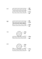
- 3C (A), 3C (B), 3C (C), and 3C (D) are cross-sectional views schematically showing various modes in which the base member and the measuring member come into contact with each other.
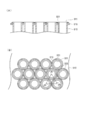
- FIG. 4 (A) is a cross-sectional view showing a tube plate to which a plurality of reaction tubes are joined
- FIG. 4 (B) is a top view of FIG. 4 (A) showing the tube plate.
- FIG. 9 A is a sectional view taken along line 9A-9A of FIG. 8, and FIG. 9 (B) is an enlarged sectional view showing a portion of 9B surrounded by the alternate long and short dash line of FIG. 9 (A). is there. It is sectional drawing which follows the line 10-10 of FIG.
- FIG. 11 (A) is a cross-sectional view corresponding to FIG. 9 (A) showing the distance measuring device of the fourth embodiment, and FIG. 11 (B) is of 11B surrounded by the alternate long and short dash line of FIG. 11 (A).
- FIG. 18 (A) is a cross-sectional view showing a tube plate to which a plurality of reaction tubes are joined
- FIG. 18 (B) is a top view of FIG. 18 (A) showing the tube plate.
- the distance measuring device of the present invention is a reactor in which a plurality of reaction tubes arranged in parallel with each other are joined to a tube plate, and the inside of the reaction tube is formed through an opening formed at the axial end of the reaction tube.
- the distance of the packed catalyst and / or inert substance to the granular solid can be measured non-contactly.
- the distance can be measured only for a part of the reactor tube contained in the reactor, or for all the reactor tubes contained in the reactor. That is, the distance can be measured for at least a part of the reaction tubes among the plurality of reaction tubes.
- the distance measuring device has a measuring member holding a length measuring device and at least one base member in which the measuring member is movably arranged.
- the angle formed by the straight line parallel to the axial length direction of the reaction tube and the reference line on the same plane is along the reference line, with the straight line parallel to the moving direction of the measuring member arranged on the base member as the reference line. It is constant for multiple reaction tubes arranged side by side.
- the measuring direction of the length measuring device is parallel to the axial length direction of the reaction tube when the measuring member is arranged on the base member, and the measuring member is from the position where the distance of one reaction tube is measured to another reaction tube. It is arranged on the base member so as to be sequentially movable to the position where the distance is measured.
- the “base member” is defined as a member capable of movably arranging the measuring member, and the specific structure is not limited as long as the measuring member can be moved.
- the “measuring member” is defined as including a length measuring device and further including a member used for arranging the base member.
- the "straight line parallel to the moving direction of the measuring member arranged on the base member” is the direction in which the measuring member moves on the projection surface when the tube plate is viewed from above in a plan view (the direction in which the measuring member moves. It means a straight line parallel to the vector).
- the "straight line parallel to the axial length direction of the reaction tube” is defined as two planes perpendicular to the projection plane when the above-mentioned tube plate is viewed from above. It means a straight line parallel to the axial length direction (vector) of the reaction tube on any projection plane.
- the measuring member placed on the base member can be slidably moved.
- the base member has, for example, a rail shape or a plate shape.
- “slide movement” means that a measuring member moves smoothly along a reference line in a state of being arranged on a base member, and a bearing, a roller, etc. provided on the measuring member or the base member, etc. It also includes a form in which the measuring member moves by rotating the bearing.
- the distance measuring device may further have support legs that support the base member and detachably attach the base member onto the tube plate.
- the base member can be placed on the tube plate via the support legs. Either a support leg with a fixed height (length) or a support leg with an adjustable height (length) can be used. The height (length) of the support leg can determine the height of the base member from the tube plate. Further, the base member can be attached to the reaction tube via a support leg inserted into the opening of the reaction tube.
- the “measuring member” includes a member used for placement on the base member.
- the member used for arranging the measuring member on the base member can be variously changed.
- the measuring member can have three or more leg members arranged on the base member, a plate member arranged on the base member, or a slider arranged on the base member.
- the measuring member is not limited to the mode of manually moving, and can have a self-propelled traveling carriage arranged on the base member.
- the phrase “arrangement” shall mean “arrangement of a certain member so as to be in contact with another member”.
- a measuring member arranged on a base member means “a measuring member that can be placed in contact with the base member”
- a state in which the measuring member is arranged on the base member means “a state in which the measuring member is arranged on the base member”.
- the state in which the measuring member is placed in contact with the base member means “the base member is placed on the tube plate", and “the base member is placed so as to be in contact with the tube plate”. It means “what you can do”.
- the phrase “contact” shall mean "a member is actually in contact with another member”.
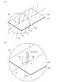
- FIG. 1 (A) is a perspective view schematically showing the distance measuring device 10 of the first embodiment
- FIG. 1 (B) is a cross-sectional view taken along line 1B-1B of FIG. 1 (A).
- FIG. 2 shows the distance from the opening 911 formed at the end of the reaction tube 910 in the axial length direction D2 to the granular solid 920 of the catalyst and / or the inert substance filled inside the reaction tube 910. It is a figure which shows typically the state which the measuring apparatus 10 sequentially measures in a non-contact manner.
- FIG. 1 (A) is a perspective view schematically showing the distance measuring device 10 of the first embodiment
- FIG. 1 (B) is a cross-sectional view taken along line 1B-1B of FIG. 1 (A).
- FIG. 2 shows the distance from the opening 911 formed at the end of the reaction tube 910 in the axial length direction D2 to the granular solid 920 of the catalyst and / or the inert substance filled inside the reaction tube 910. It is a figure which
- FIG. 3A when the straight line parallel to the moving direction of the measuring member arranged on the base member is defined as the reference line L0, the straight line L1 parallel to the axial length direction of the reaction tube 910 and the reference line L0 are the same.
- FIG. 3B (A) is a perspective view showing the relationship between the contact surface 220 of the base member 200 and the axial length direction D2 of the reaction tube 910, and FIG. 3B (B) is surrounded by the alternate long and short dash line of FIG. 3B (A). It is a perspective view which shows the part of 3B enlarged.
- FIG. 4A is a cross-sectional view showing a tube plate 916 to which a plurality of reaction tubes 910 are joined
- FIG. 4B is a top view showing a tube plate 916
- FIG. 5 is a diagram schematically showing a reactor 900 provided with a plurality of reaction tubes 910 and measuring the distance from the opening 911 of the reaction tube 910 to the solid matter 920. .. The straight line Lm shown by the alternate long and short dash line in FIG.
- FIG. 1A indicates a row of reaction tubes 910 for measuring the space length by sequentially moving the measuring member 300.
- Reference numerals P1, P2, and P3 shown in FIG. 2 schematically indicate positions where the space length is measured by the length measuring device 100.
- the axial length direction D2 of the reaction tube 910 is the vertical direction in FIGS. 2 and 5.
- the distance measuring device 10 is generally described in a reactor 900 in which a plurality of reaction tubes 910 arranged in parallel with each other are joined to a tube plate 916.
- the catalyst and / or the inert substance filled inside the reactor tube 910 through the opening 911 formed at the end of the reactor tube 910 in the axial length direction D2.
- the distance measuring device 10 can have a measuring member 300 holding the length measuring device 100 and at least one rail member 200 (corresponding to a base member) in which the measuring member 300 is movably arranged. As shown in FIG.
- a straight line L0 parallel to the direction in which the measuring member 300 arranged on the rail member 200 moves is defined as a reference line L0, and a straight line L1 and a reference line L0 parallel to the axial length direction D2 of the reaction tube 910.
- the angle ⁇ formed by and on the same plane N is constant for a plurality of reaction tubes 910 arranged along the reference line L0.
- the measuring direction D1 of the length measuring instrument 100 is parallel to the axial length direction D2 of the reaction tube 910 in a state where the measuring member 300 is arranged on the rail member 200.
- the measuring member 300 can be arranged on the rail member 200 so as to be sequentially movable from the position P1 (P2) where the distance of one reaction tube 910 is measured to the position P2 (P3) where the distance of the other reaction tube 910 is measured. ..
- the reactor 900 has a plurality of reaction tubes 910 arranged in parallel with each other.
- the plurality of reaction tubes 910 in the reactor 900 are usually arranged in the form of a triangular complex, a square series, a square complex, or the like so that the distances between adjacent reaction tubes are as equal as possible.
- the plurality of reaction tubes 910 are arranged at a predetermined pitch pa (see FIG. 4B).
- the upper ends of the plurality of reaction tubes 910 are joined to the tube plate 916 by welding.
- the surface of the tube plate is uneven due to welding marks such as welding beads and spatter, and uneven parts are formed.
- the welding marks are concentrated on the outer peripheral portion of the reaction tube 910. Therefore, there is no welding mark in the intermediate portion between one reaction tube 910 and the other reaction tube 910 adjacent thereto, and the tube plate 916 can have a smooth surface 930.
- the angle between the smooth surface 930 of the tube plate 916 and the axial length direction D2 of the reaction tube 910 is constant, and normally the axial length direction D2 of the reaction tube 910 is perpendicular to the smooth surface 930 of the tube plate 916.
- the measuring member 300 can be arranged on the contact surface 220 of the rail member 200.
- the contact surface 220 of the rail member 200 can be a smooth, continuous flat surface.
- the measuring member 300 slides while being arranged on the contact surface 220 and keeping the measuring direction D1 of the length measuring instrument 100 parallel to the axial length direction D2 of the reaction tube 910. It is possible.
- the distance measuring device 10 can have a plurality of rail members 200. When the tube plate 916 is viewed from above in a plan view, a plurality of (for example, two) rail members 200 can be arranged in parallel.
- the rail member 200 can be composed of a member having a rail-shaped cross section.
- the leg member 303 described later of the measuring member 300 can have a tip portion having a sharp shape (spike shape).
- the rail member 200 can have a guide groove 221 that guides the tip of the leg member 303 so as not to come off.
- the distance measuring device 10 can further have a support leg 201 that supports the rail member 200 and detachably attaches the rail member 200 onto the pipe plate 916.
- the support legs 201 can be attached to the lower surface of the rail member 200.
- the rail member 200 can be arranged on the smooth surface 930 of the pipe plate 916 via the support legs 201.
- the support legs 201 do not necessarily have to be arranged on the smooth surface 930 of the tube plate 916, and the rail member 200 may be stably arranged without wobbling.
- the rail member 200 can be fixed to the outer peripheral wall of the reactor 900, the reaction tube 910, or the like by a clamp jig or the like (not shown).
- the shape and structure of the support legs are not limited as long as the rail member 200 is supported and the rail member 200 can be detachably mounted on the pipe plate 916.
- it can have an elongated rod shape, a hollow pipe shape, or a plate shape.
- the straight line L0 shown in FIG. 3A indicates a straight line parallel to the direction in which the measuring member arranged on the base member moves. This straight line is referred to as "reference line L0".
- the straight line L1 indicates a straight line parallel to the axial length direction of the reaction tube 910.
- the plurality of reaction tubes 910 are parallel to each other. Therefore, the angle ⁇ formed by the straight line L1 and the reference line L0 on the same plane N is constant for a plurality of reaction tubes 910 arranged along the reference line L0.
- the reference line L0 is a reaction of measuring the space length by sequentially moving the straight line Lm (measurement member 300 is sequentially moved) attached to FIGS.
- the X-axis and Y-axis shown in FIGS. 3B (A) and 3B (B) show two straight lines on the contact surface 220 of the rail member 200, and the X-axis and the Y-axis are orthogonal to each other.
- the Z-axis represents a straight line perpendicular to the two straight lines of the X-axis and the Y-axis, and is perpendicular to the contact surface 220.
- the origin of the XYZ coordinates coincides with the point where the axial length direction D2 of the reaction tube 910 passes through the contact surface 220.
- the straight line Lm indicates a row of reaction tubes 910 for measuring the space length by sequentially moving the measuring member 300.
- FIG. 3B (B) shows that the axial length direction D2 of the reaction tube 910 is inclined so as not to pass over the Z axis but to pass through the points (x0, y0, z0) of the XYZ coordinates.
- the angle ⁇ formed by the straight line L1 parallel to the axial length direction D2 of the reaction tube 910 and the reference line L0 on the same plane N is for a plurality of reaction tubes 910 arranged along the reference line L0. It is constant.
- the measurement direction D1 of the length measuring instrument 100 is the reaction tube 910 while the measuring member 300 is arranged on the rail member 200.
- the distance (space length) from the opening 911 of the reaction tube 910 to the solid matter 920 can be measured by making it parallel to the axial length direction D2 of.
- the shape (structure) at which the base member and the measuring member come into contact may be any shape (structure) that allows the measuring member to slide straight when the measuring member is arranged on the base member.
- the contact surface 341a of the base member 341 is a smooth continuous flat surface
- the contact surface 342a of the measurement member 342 is a smooth continuous flat surface
- the base member 341 and the measurement member 342 Can be contacted on a "plane”.
- FIG. 3C (A) the contact surface 341a of the base member 341 is a smooth continuous flat surface
- the contact surface 342a of the measurement member 342 is a smooth continuous flat surface
- the base member 341 and the measurement member 342 Can be contacted on a "plane”.
- the contact surface 343a of the base member 343 is formed as an uneven surface protruding in a triangular shape
- the contact surface 344a of the measuring member 344 is formed as a smooth continuous flat surface
- the base member 343 and the measuring member 344 Can be contacted by a "line”.
- the direction in which the measuring member 344 slides is the direction orthogonal to the paper surface.
- the contact surface 345a of the base member 345 is a smooth and continuous flat surface
- the contact surface 346a of the measurement member 346 is a spherical surface such as a bearing
- the base member 345 and the measurement member 346 are “points”. Can be contacted with.
- the contact surface 347a of the base member 347 is a curved surface
- the contact surface 348a of the measurement member 348 is a spherical surface such as a bearing
- the base member 347 and the measurement member 348 are designated as "points". Can be contacted.
- the contact surface 347a of the base member 347 can have a shape like an inner surface cut from a pipe, and becomes a smooth straight line in the direction in which the measuring member 348 slides (the direction orthogonal to the paper surface). In the direction orthogonal to the direction in which the measuring member 348 slides (the direction of the paper surface), the curved surface is convex downward.
- the measuring member can be slidably moved while being arranged on the base member.
- the model of the length measuring device 100 is not limited as long as it measures the distance in a non-contact manner.
- the length measuring device 100 for example, a known device that measures a distance in a non-contact manner using a laser, a sound wave, or a microwave can be used, and a laser type length measuring device is particularly preferable.
- the principle of the laser length measuring instrument is roughly divided into the triangular ranging type, the time of flight type, and the phase difference type, but the principle is not particularly limited.
- the type of laser is not particularly limited, but a laser having a wavelength of 635 nm is generally used.
- laser rangefinder models include a laser rangefinder manufactured by Bosch Corporation (model number GLM50C, model number GLM150C, etc.) and a laser rangefinder manufactured by Leica Geosystems Co., Ltd. (Leica DISTO (registered trademark) D1. , Leica DISTO (registered trademark) D810, Leica DISTO (registered trademark) X3, etc.) and other handy type models are on sale.
- Some laser length measuring instruments come with an inclination measuring function that displays the inclination of the main body, which is preferable because it can be used as an index when calibrating the irradiation direction.
- module type models such as the laser distance sensor (LDS-7A, etc.) manufactured by Takenaka Denshi Kogyo Co., Ltd., which is used by incorporating it into a PC or device, are also on sale.
- the vessel can also be applied to the present invention.
- the leg member 303 of the book can be provided.
- the three leg members 303 can be composed of, for example, a tripod.
- Each of the leg members 303 has a stretchable structure, and the length can be adjusted.
- all the tip portions of the leg member 303 can be arranged on the contact surface 220.
- Two of the three leg members 303 can be arranged on the contact surface 220 of one rail member 200 of the two rail members arranged in parallel, and the remaining one is on the contact surface 220 of the other rail member 200.
- the measuring member 300 can have four or more leg members 303 arranged on the contact surface 220 of the rail member 200.
- the four leg members 303 can be composed of, for example, four legs.
- the adapter 301 can have an adjustment mechanism (not shown) for adjusting the direction of the measurement direction D1 of the length measuring device 100.
- the adjusting mechanism has a free pan head, a plurality of thumbscrew type fixtures, and the like, and can freely adjust the measuring direction D1 of the length measuring instrument 100.
- the measuring direction D1 of the length measuring device 100 is parallel to the axial length direction D2 of the reaction tube 910 in a state where all the leg members 303 are in contact with the contact surface 220 (a state in which the measuring member 300 is arranged on the contact surface 220). ing.
- the measurement direction D1 of the length measuring device 100 is adjusted as follows, for example. First, the measuring member 300 is arranged on the contact surface 220 of the rail member 200 so that all the tip portions of the leg members 303 of the measuring member 300 are in contact with the contact surface 220. From the row of reaction tubes 910 (straight line Lm in FIG. 1A) for measuring the space length by sliding the measuring member 300, first, the space length is measured with a measure or the like for any one reaction tube 910. Next, the fixing screw of the free platform is loosened so that the space length is measured, and the laser irradiation direction and angle of the length measuring instrument 100 are adjusted. After the adjustment, tighten the fixing screw of the free platform to fix the length measuring instrument 100.
- the distance actually measured by the length measuring instrument 100 is the distance from the tip of the length measuring instrument 100 to the solid matter 920.
- the tip of the length measuring instrument 100 may be on the upper end of the reaction tube 910 (on the horizontal plane of the opening 911) at the time of measurement. ), It may be necessary to offset the length measurement result.
- the offset dimension between the tip of the length measuring device 100 and the upper end of the reaction tube 910 can be measured in advance and stored in the length measuring device 100 as correction data.
- the distance actually measured by the length measuring device 100 can be corrected based on the offset dimension. Thereby, the distance from the opening 911 of the reaction tube 910 to the solid matter 920 can be measured.
- the angle ⁇ formed by the straight line L1 parallel to the axial length direction D2 of the reaction tube 910 and the reference line L0 on the same plane N is for a plurality of reaction tubes 910 arranged along the reference line L0. It is constant (see FIG. 3A). Further, the measuring direction D1 of the length measuring device 100 is parallel to the axial length direction D2 of the reaction tube 910 in a state where the measuring member 300 is arranged on the rail member 200. Therefore, even if the measuring member 300 is slid along the contact surface 220 of the rail member 200, the measuring direction D1 of the length measuring instrument 100 is parallel to the axial length direction D2 of any reaction tube 910 for measuring the space length. Eggplant. Therefore, when measuring the space lengths of different reaction tubes, it is possible to measure the space lengths of a plurality of reaction tubes 910 without adjusting the angle of the length measuring device 100.
- the smooth surface 930 of the tube plate 916 on which the rail member 200 is placed usually has a constant angle with the axial length direction D2 of the reaction tube 910, the measurement direction of the length measuring instrument 100 In many cases, fine adjustment is sufficient for the adjustment work of D1.
- the measuring direction D1 of the length measuring device 100 faces the axial length direction D2.
- “facing” means that the measurement direction D1 measured by the length measuring instrument 100, that is, the irradiation direction of the irradiation wave for distance measurement (for example, the laser beam of the laser type length measuring instrument 100) is downward and the axial length is long. It means that it is almost parallel to the direction D2.
- the measuring direction D1 of the length measuring instrument 100 is parallel to the axial length direction D2 of the reaction tube 910
- the distance from the opening 911 to the solid 920 can be measured, and the case where the reaction tube 910 deviates from the axial length direction D2 by a small angle is also included.
- the measuring member 300 is slid to the position P1, and the length measuring instrument 100 can measure the distance (space length) from the opening 911 of the reaction tube 910 to the solid matter 920 at the position P1. .. After that, the measuring member 300 is slid from the position P1 to the position P2, and the length measuring instrument 100 can measure the distance from the opening 911 of the reaction tube 910 to the solid matter 920 at the position P2. After that, the measuring member 300 is slid from the position P2 to the position P3, and the length measuring instrument 100 can measure the distance from the opening 911 of the reaction tube 910 to the solid matter 920 at the position P3.
- the measuring member 300 can slide and move sequentially from the position P1 (P2) where the distance of one reaction tube 910 is measured to the position P2 (P3) where the distance of the other reaction tube 910 is measured. Can be arranged on the contact surface 220 of.
- the distance measuring device 10 may have a mechanism for displaying whether or not the measured space length is within the permissible range.
- the pass / fail display may be in the form of being displayed on the screen, or may be provided with a mechanism for making a sound as needed.
- the distance measuring device 10 may have a mechanism for transferring the measurement result to a personal computer, a mobile terminal, or the like by Bluetooth (registered trademark) or the like and accumulating the data.
- Reactor 900 including a plurality of reaction tubes 910 will be described with reference to FIG. 5 again.
- the reaction tube 910 can be incorporated into, for example, a multi-tube reactor 900 installed in a chemical plant in the field of the petrochemical industry. Thousands to tens of thousands of reaction tubes 910 can be incorporated into one reactor 900.
- the reaction tube 910 can be filled with, for example, a granular catalyst, granular ceramics (for example, silica, alumina, or zirconia spheres or rings), granular metal Raschig rings, and the like.
- a lower end opening 913 that communicates with the outside of the reaction tube 910 can be formed.
- the reaction tube 910 can be formed into a straight tube having an inner diameter of 10 mm to 60 mm and a height of 1000 mm to 15000 mm, although it depends on the desired contact reaction.
- the inside of the reaction tube 910 may be filled with only solids of the same type, and for example, as shown in FIG. 5, a plurality of layers 914 and 915 composed of solids M1 and M2 of different types are provided. , The reaction tube 910 may be filled at different positions in the height direction.
- the first layer 914 can be composed of granular solids M1.
- the second layer 915 can be composed of granular solid matter M2.
- the solid substance M1 for example, a spherical catalyst for contact reaction molded to have an outer diameter of 1 mm to 15 mm can be used.
- the solid material M2 for example, a metal Raschig ring molded into a ring shape (cylindrical shape) can be used.
- another layer is further formed inside the reaction tube 910 on the lower end side of the second layer 915 by a solid substance of the same kind or a different kind as the solid substance M1 or the solid substance M2. You may be.
- the types of solids M1 and M2 are not limited to those exemplified. Further, the shape and size of the solids M1 and M2 are not limited. Further, the form (number of layers, height of each layer, etc.) in which the solids M1 and M2 are filled inside the reaction tube 910 is not limited.
- FIG. 6 is a perspective view schematically showing the distance measuring device 11 of the second embodiment
- FIG. 7 is a cross-sectional view taken along the line 7-7 of FIG.
- the members common to the above-described embodiments are designated by the same reference numerals, and some description thereof will be omitted.
- the straight lines Lm1 and Lm2 shown by the alternate long and short dash line in FIG. 6 show a row of reaction tubes 910 for measuring the space length by sequentially moving the two measuring members 305 and 306.
- Reference numerals P1, P2, and P3 shown in FIG. 6 schematically indicate positions where the space length is measured by the length measuring device 100.
- the base member is not limited to the case where it is positioned near the tube plate 916 as in the first embodiment, and can be appropriately modified to a form where it is located above the tube plate 916.
- the space between the tube plate 916 and the base member can be used as the moving space of the measuring members 305 and 306.
- the measuring members 305 and 306 holding the length measuring device 100 and the rail member 202 in which the measuring members 305 and 306 are movably arranged are arranged. (Corresponding to the base member) and can have.
- the distance measuring device 11 can have a plurality of measuring members 305 and 306 (two in the figure), and can have a plurality of length measuring devices 100 (two in the figure).
- two straight lines parallel to the moving direction of the two measuring members 305 and 306 arranged on the rail member 202 are designated as reference lines L01 and L02. To do.
- the reference lines L01 and L02 are the straight lines Lm1 and Lm2 (two measuring members 305 and 306 are sequentially moved to measure the space length of the reaction tube 910) shown in FIG. Is parallel to the row). Similar to that described in FIG. 3A, the angle formed by the straight line L11 parallel to the axial length direction D2 of the reaction tube 910 and the reference line L01 on the same plane is a plurality of reaction tubes arranged along the reference line L01. It is constant for 910. The angle formed by the straight line L12 parallel to the axial length direction D2 of the reaction tube 910 and the reference line L02 on the same plane is constant for a plurality of reaction tubes 910 arranged along the reference line L02.
- the measuring direction D1 of the length measuring device 100 is parallel to the axial length direction D2 of the reaction tube 910 in a state where the measuring members 305 and 306 are arranged on the rail member 202. Then, the measuring members 305 and 306 can be sequentially moved from the position P1 (P2) where the distance of one reaction tube 910 is measured to the position P2 (P3) where the distance of the other reaction tube 910 is measured to the rail member 202. Can be placed.
- the measuring members 305 and 306 can be arranged on the contact surfaces 222 and 223 of the rail member 202.
- the contact surfaces 222 and 223 of the rail member 202 can be smooth and continuous flat surfaces.
- the measuring members 305 and 306 were kept arranged on the contact surfaces 222 and 223, and the measuring direction D1 of the length measuring instrument 100 was kept parallel to the axial length direction D2 of the reaction tube 910.
- the slide can be moved as it is.
- the rail member 202 is viewed from above in a plan view, the two contact surfaces 222 and 223 can be arranged in parallel.
- One measuring member 305 can be arranged on one contact surface 222, and the other measuring member 306 can be arranged on the other contact surface 223.
- the rail member 202 can be composed of a member having a rail-shaped cross section.
- the rail member 202 of the second embodiment can be formed from, for example, a lower casing 203 and an upper casing 204 that covers the lower casing 203.
- the rail member 202 can have slide grooves 205, 206 into which the sliders 307, 308 described later included in the measuring members 305, 306 are fitted.
- the lower surfaces of the slide grooves 205 and 206 serve as contact surfaces 222 and 223.
- the measuring members 305 and 306 can hang down from the rail member 202 when the lower surfaces of the sliders 307 and 308 come into contact with the contact surfaces 222 and 223 of the slide grooves 205 and 206.
- the distance measuring device 11 can further have a support leg 401 that supports the rail member 202 and detachably attaches the rail member 202 onto the pipe plate 916.
- the rail member 202 can be arranged on the smooth surface 930 of the pipe plate 916 via the support legs 401.
- the support legs 401 do not necessarily have to be arranged on the smooth surface 930 of the pipe plate 916, and the rail member 202 may be stably arranged without wobbling.
- the support leg 401 can position the rail member 202 at an upper position of the pipe plate 916.
- the structure of the support leg 401 is not particularly limited as long as it does not interfere with the movement of the measuring members 305 and 306, but can be composed of, for example, a tripod or a quadruped (tripod in the illustrated example).
- Each support leg 401 has a stretchable structure, and the height of the rail member 202 from the tube plate 916 can be adjusted.
- the space between the tube plate 916 and the rail member 202 can be used as a moving space for the measuring members 305 and 306.
- the axial length direction D2 of the reaction tube 910 is not necessarily the contact surface 222, 223 of the rail member 202. It does not have to be perpendicular to. Even when the axial length direction D2 of the reaction tube 910 is not perpendicular to the contact surfaces 222 and 223 of the rail member 202, the measuring direction D1 of the length measuring instrument 100 is in the state where the measuring members 305 and 306 are arranged on the rail member 202. Is parallel to the axial length direction D2 of the reaction tube 910, so that the distance (space length) from the opening 911 of the reaction tube 910 to the solid matter 920 can be measured.
- the measuring members 305 and 306 can have adapters 310 and 311 for holding the length measuring device 100 and sliders 307 and 308 arranged on the contact surfaces 222 and 223 of the rail member 202.
- the sliders 307 and 308 can be provided on top of the adapters 310 and 311. By providing the sliders 307 and 308, the measuring members 305 and 306 can be smoothly slid and moved along the rail member 202.
- the adapters 310 and 311 can have an adjustment mechanism for adjusting the direction of the measurement direction D1 of the length measuring device 100. Similar to the adapter 301 of the first embodiment described above, the adjusting mechanism has a free platform, a plurality of thumbscrew type fixtures, and the like, and can freely adjust the measuring direction D1 of the length measuring instrument 100.
- the measurement direction D1 of the length measuring device 100 is the axial length direction D2 of the reaction tube 910 in a state where the sliders 307 and 308 are in contact with the contact surfaces 222 and 223 (the state where the measurement members 305 and 306 are arranged on the rail member 202). It is parallel.
- the measurement direction D1 of the length measuring device 100 may be adjusted by the same method as described in the first embodiment described above. In the case of the second embodiment illustrated in FIGS. 6 and 7, since the two length measuring instruments 100 are provided, the measuring direction D1 of the two length measuring instruments 100 is adjusted.
- the rail member 202 having two contact surfaces 222 and 223 is illustrated, but it can be modified into a rail member having only one contact surface or a rail member having three or more contact surfaces. ..
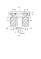
- FIG. 9A is a sectional view taken along the line 9A-9A of FIG. 8
- FIG. 9B is FIG. 9 (B). It is sectional drawing which shows the part of 9B surrounded by the two-dot chain line of A) enlarged.
- FIG. 10 is a cross-sectional view taken along the line 10-10 of FIG.
- the members common to the above-described embodiments are designated by the same reference numerals, and some description thereof will be omitted.
- FIG. 8 indicate a row of reaction tubes 910 in which the measuring member 315 is sequentially moved and the space length is measured by a plurality of length measuring instruments 100.
- Reference numerals P1, P2, and P3 shown in FIG. 8 schematically indicate positions where the space length is measured by one length measuring device 100.
- the third embodiment is common to the second embodiment in that the base member is positioned above the tube plate 916, but differs from the second embodiment in the specific shape of the base member and the measuring member.
- the distance measuring device 12 of the third embodiment includes a measuring member 315 holding the length measuring device 100 in a hanging state. It may have a rail member 207 (corresponding to a base member) in which the measuring member 315 is movably arranged.
- the measuring member 315 can have a plurality of length measuring instruments 100 (four in the figure).
- the plurality of length measuring instruments 100 can be arranged according to the pitch pa of the reaction tube 910.
- four straight lines parallel to the moving direction of the measuring member 315 arranged on the rail member 207 are set as reference lines L01, L02, L03, and L04. ..
- the reference lines L01, L02, L03, and L04 are the straight lines Lm1, Lm2, Lm3, and Lm4 (the measuring members 315 are sequentially moved to be a plurality of length measuring instruments). It is parallel to the row of reaction tubes 910 whose space length is measured by 100). Similar to that described in FIG. 3A, the angle formed by the straight line L11 parallel to the axial length direction D2 of the reaction tube 910 and the reference line L01 on the same plane is a plurality of reaction tubes arranged along the reference line L01. It is constant for 910.
- the angle formed by the straight line L12 parallel to the axial length direction D2 of the reaction tube 910 and the reference line L02 on the same plane is constant for a plurality of reaction tubes 910 arranged along the reference line L02.
- the angle formed by the straight line L13 parallel to the axial length direction D2 of the reaction tube 910 and the reference line L03 on the same plane is constant for a plurality of reaction tubes 910 arranged along the reference line L03.
- the angle formed by the straight line L14 parallel to the axial length direction D2 of the reaction tube 910 and the reference line L04 on the same plane is constant for a plurality of reaction tubes 910 arranged along the reference line L04.
- the measuring direction D1 of the length measuring device 100 is parallel to the axial length direction D2 of the reaction tube 910 in a state where the measuring member 315 is arranged on the rail member 207. Then, the measuring member 315 can be arranged on the rail member 207 so as to be sequentially movable from the position P1 (P2) where the distance of one reaction tube 910 is measured to the position P2 (P3) where the distance of the other reaction tube 910 is measured. ..
- the measuring member 315 can be slidably moved while being arranged on the rail member 207 and keeping the measuring direction D1 of the length measuring instrument 100 parallel to the axial length direction D2 of the reaction tube 910. ..
- the distance measuring device 12 can have a plurality of rail members 207. When the tube plate 916 is viewed in a plan view from above, a plurality of (for example, two) rail members 207 can be arranged in parallel.
- the rail member 207 can be composed of a member having a rail-shaped cross section.
- the rail member 207 of the third embodiment can be composed of, for example, the rail of the linear guide 236.
- the movable block 230 of the linear guide 236 that fits the rail member 207 can be provided on the slider 317 described later included in the measuring member 315.
- the movable block 230 of the linear guide 236 has a built-in bearing and can slide straight along the rail member 207 by the rolling motion of the bearing.
- the rail and the movable block in the linear guide are usually in point contact between the curved surface on the rail side and the spherical surface of the bearing.
- the measurement member 315 can be hung from the rail member 207 by fitting the movable block 230 of the slider 317 into the rail member 207.
- the distance measuring device 12 can further have a support leg 406 that supports the rail member 207 and detachably attaches the rail member 207 onto the tube plate 916.
- the rail member 207 can be arranged on the smooth surface 930 of the tube plate 916 via the support legs 406.
- the support legs 406 do not necessarily have to be arranged on the smooth surface 930 of the tube plate 916, and the rail member 207 may be stably arranged without wobbling.
- the support leg 406 can position the rail member 207 at an upper position of the pipe plate 916.
- the structure of the support leg 406 is not particularly limited as long as it does not interfere with the movement of the measuring member 315.
- an angle material can be used for the support leg 406, for example.
- Each support leg 406 has a stretchable structure, and the height of the rail member 207 from the tube plate 916 can be adjusted.
- the space between the tube plate 916 and the rail member 207 can be used as a moving space for the measuring member 315.
- the support leg 406 can support the rail member 207 via the frame body 231 on which the rail member 207 is installed.
- the frame body 231 can be formed of flat steel.
- the support legs 406 can directly support the rail member 207 and can be detachably mounted on the tube plate 916 without the need for the frame body 231.
- the distance measuring device 12 can have a drive unit 232 that slides the measuring member 315 along the rail member 207.
- the structure of the drive unit 232 is not limited, but for example, as shown in FIGS. 8, 9 (A), and 10, the drive unit 232 includes a ball screw 233 rotatably supported by the frame body 231 and a ball. It can have a motor 234 that rotationally drives the screw 233 and an actuating plate 235 through which the ball screw 233 is inserted.
- the motor 234 can be attached to the frame body 231.
- the actuating plate 235 can be attached to the slider 317 of the measuring member 315.
- the ball screw 233 can be fitted into the screw hole of the operating plate 235.
- the operation plate 235 moves in the axial direction of the ball screw 233 because the ball screw 233 is fitted. To do. As a result, the measuring member 315 can move forward in the direction indicated by the white arrow in FIG. When the ball screw 233 is rotationally driven in the opposite direction by the motor 234, the measuring member 315 can move backward in the opposite direction.
- the movable block 230 that fits the rail member 207 slides straight.
- the upper surface of the movable block 230 is referred to as a slide surface 225 of the rail member 207 for convenience of explanation.
- the axial length direction D2 of the reaction tube 910 is not necessarily perpendicular to the slide surface 225 of the rail member 207, as described in FIGS. 3B (A) and 3B (B). It does not have to be.
- the measurement direction D1 of the length measuring instrument 100 is the reaction tube 910 in the state where the measurement member 315 is arranged on the rail member 207.
- the distance (space length) from the opening 911 of the reaction tube 910 to the solid matter 920 can be measured by making it parallel to the axial length direction D2 of.
- the measuring member 315 can have an adapter 316 that holds the length measuring device 100 in a hanging state, and a slider 317 that is arranged on the rail member 207.
- a plurality of adapters 316 (for example, four in the illustrated example) can be arranged on the lower surface of one slider 317. By providing the slider 317, the measuring member 315 can be smoothly slid and moved along the rail member 207.
- the surface of the slider 317 that holds the adapter 316 is parallel to the slide surface 225 of the rail member 207.
- the adapter 316 can have an adjustment mechanism for adjusting the direction of the measurement direction D1 of the length measuring device 100. Similar to the adapter 301 of the first embodiment described above, the adjusting mechanism has a free platform, a plurality of thumbscrew type fixtures, and the like, and can freely adjust the measuring direction D1 of the length measuring instrument 100.
- the measuring direction D1 of the length measuring device 100 is parallel to the axial length direction D2 of the reaction tube 910 in a state where the measuring member 315 is arranged on the rail member 207.
- the measurement direction D1 of the length measuring device 100 may be adjusted by the same method as described in the first embodiment described above. Since the third embodiment has four length measuring instruments 100, the measurement direction D1 of the four length measuring instruments 100 is adjusted.
- the case of having four length measuring instruments 100 is illustrated, but it is possible to have one to three length measuring instruments 100 and five or more length measuring instruments 100.
- ⁇ Distance measuring device 13 (fourth embodiment)> 11 (A) is a cross-sectional view corresponding to FIG. 9 (A) showing the distance measuring device of the fourth embodiment, and FIG. 11 (B) is of 11B surrounded by the alternate long and short dash line of FIG. 11 (A). It is sectional drawing which shows the part enlarged.
- the members common to the above-described embodiments are designated by the same reference numerals, and some description thereof will be omitted.
- the fourth embodiment is different from the third embodiment in the specific shape of the base member, and is common to the third embodiment in other respects.
- the measuring member 242 holding the length measuring device 100 in a hanging state and the measuring member 242 can be moved. It can have a rail member 240 (corresponding to a base member) to be arranged.
- the rail member 240 can be composed of a member having a rail-shaped cross section.
- the rail member 240 of the fourth embodiment can have a recess 243 having a concave cross section.
- the block 244 that fits into the recess 243 of the rail member 240 can be provided on the slider 246 of the measuring member 242.
- the block 244 of the slider 246 is guided along the rail member 240 by the sliding motion between the convex portion 245 of the block 244 and the concave portion 243 of the rail member 240.
- the bottom surface of the recess 243 of the rail member 240 serves as the contact surface 241.
- the distance measuring device 13 can have a drive unit 232 that slides the measuring member 242 along the rail member 240.
- the drive unit 232 can be configured in the same manner as in the third embodiment.
- FIG. 12 is a perspective view schematically showing the distance measuring device 14 of the fifth embodiment.
- the members common to the above-described embodiments are designated by the same reference numerals, and some description thereof will be omitted.
- the straight line Lm shown by the alternate long and short dash line in FIG. 12 indicates a row of reaction tubes 910 for measuring the space length by sequentially moving the measuring member 320.
- the measuring member 320 of the fifth embodiment can have an adapter 301 for holding the length measuring device 100 and a plate member 321 arranged on the contact surface 220 of the rail member 200.
- the pair of plate members 321 can be connected to the top plate 322 to form a substantially box shape.
- the adapter 301 is attached to the top plate 322.
- the measuring member 320 can be arranged so that the lower end surface of the plate member 321 is in surface contact with the contact surface 220. When the plate member 321 comes into surface contact, the measuring member 320 can be stably arranged on the contact surface 220.
- FIG. 13 is a cross-sectional view corresponding to FIG. 1B showing the distance measuring device 15 of the sixth embodiment.
- the members common to the above-described embodiments are designated by the same reference numerals, and some description thereof will be omitted.
- the measuring member 300 of the sixth embodiment can have a slider 325 arranged on the contact surface 220 of the rail member 200.
- the slider 325 can be connected to the tip of the leg member 303 via a ball joint 326.
- the slider 325 can be arranged on the contact surface 220 of the rail member 200 regardless of the posture of the leg member 303. By providing the slider 325, the measuring member 300 can be smoothly slid and moved along the rail member 200.
- FIG. 14 is a cross-sectional view corresponding to FIG. 2 showing the distance measuring device 16 of the seventh embodiment.
- the members common to the above-described embodiments are designated by the same reference numerals, and some description thereof will be omitted.
- the base member is not limited to the case where it is mounted on the tube plate 916, and can be appropriately modified.
- the distance measuring device 16 of the seventh embodiment can have a rail member 200 (corresponding to a base member) in which the measuring member 300 is movably arranged.
- the distance measuring device 16 may further have a support leg 210 that supports the rail member 200 and detachably attaches the rail member 200 onto the tube plate 916.
- the support legs 210 can be attached to the lower surface of the rail member 200.
- the support leg 210 of the seventh embodiment can have a tapered shape in which the tip on the lower end side is tapered. The tip of the support leg 210 can enter the inside of the reaction tube 910 beyond the opening 911 of the reaction tube 910.
- the base end on the upper end side of the support leg 210 can have an outer diameter dimension larger than the inner diameter dimension of the opening 911 of the reaction tube 910. Then, the rail member 200 is attached to the reaction tube 910 via a support leg 210 inserted into the opening 911 of the reaction tube 910.
- the rail member 200 as the base member can be laid even when the pipe plate 916 does not have a portion where the base member can be stably arranged.
- the contact surface 220 does not necessarily have to be perpendicular to the axial length direction D2 of the reaction tube 910, as described in FIGS. 3B (A) and 3B (B).
- the measurement direction D1 of the length measuring instrument 100 is the axial length direction of the reaction tube 910 in the state where the measuring member 300 is arranged on the contact surface 220. By making it parallel to D2, the distance (space length) from the opening 911 of the reaction tube 910 to the solid matter 920 can be measured.
- FIG. 15 is a cross-sectional view corresponding to FIG. 2 showing the distance measuring device 17 of the eighth embodiment.
- the members common to the above-described embodiments are designated by the same reference numerals, and some description thereof will be omitted.
- Reference numerals P1, P2, and P3 shown in FIG. 15 schematically indicate positions where the space length is measured by the length measuring device 100.
- the base member is not limited to having a rail shape, and can be appropriately modified. Further, the measuring member is not limited to the mode of manually moving by the measurer, and can be appropriately modified.
- the distance measuring device 17 of the eighth embodiment has a measuring member 330 holding the length measuring device 100 and a plate member 215 (corresponding to a base member) in which the measuring member 330 is movably arranged. And can have.
- the measuring member 330 of the eighth embodiment can have a self-propelled traveling carriage 333 arranged on the plate member 215.
- the measurement direction D1 of the length measuring device 100 is parallel to the axial length direction D2 of the reaction tube 910 in a state where the traveling carriage 333 is arranged on the plate member 215.
- the traveling carriage 333 can be arranged on the plate member 215 so as to be sequentially movable from the position P1 (P2) where the distance of one reaction tube 910 is measured to the position P2 (P3) where the distance of the other reaction tube 910 is measured. ..
- the contact surface 227 of the plate member 215 can be a smooth and continuous flat surface.
- the traveling carriage 333 can be slidably moved while being arranged on the plate member 215 and keeping the measurement direction D1 of the length measuring device 100 parallel to the axial length direction D2 of the reaction tube 910. ..
- the plate member 215 can be composed of a member having a plate shape.
- the plate member 215 can be formed from a perforated plate in which a plurality of through holes 217 are formed.
- the through hole 217 can have approximately the same size as the opening 911 or slightly wider than the opening 911.
- the plurality of through holes 217 can be formed according to the pitch pa of the reaction tube 910.
- the plate member 215 can be attached to the reactor 900 so that the through hole 217 and the opening 911 substantially overlap.
- the distance measuring device 17 can further have a support leg 201 that supports the plate member 215 and detachably attaches the plate member 215 onto the tube plate 916.
- the support legs 201 can be attached to the lower surface of the plate member 215.
- the plate member 215 can be arranged on the smooth surface 930 of the tube plate 916 via the support legs 201.
- the support legs 201 do not necessarily have to be arranged on the smooth surface 930 of the tube plate 916, and the plate members 215 may be stably arranged without wobbling.
- the plate member 215 can be fixed to the outer peripheral wall of the reactor 900, the reaction tube 910, or the like by a clamp jig or the like (not shown).
- the axial length direction D2 of the reaction tube 910 is not necessarily perpendicular to the contact surface 227. Good. Even when the axial length direction D2 of the reaction tube 910 is not perpendicular to the contact surface 227, the measurement direction D1 of the length measuring device 100 is the axial length direction of the reaction tube 910 in the state where the traveling carriage 333 is arranged on the plate member 215. By making it parallel to D2, the distance (space length) from the opening 911 of the reaction tube 910 to the solid matter 920 can be measured.
- the traveling carriage 333 has an adapter 331 that holds the length measuring device 100, and can self-propell on the contact surface 227 of the plate member 215.
- the traveling carriage 333 can have wheels that are rotationally driven by a motor or the like, a controller that controls the driving of the motor or the measurement operation of the length measuring device 100, a memory for storing control programs and data, a battery, and the like.
- the traveling trolley 333 can be connected to an external personal computer, mobile terminal, or the like by Bluetooth (registered trademark) or the like, and can transmit and receive data and control signals to and from an external device.
- the traveling carriage 333 can be guided by a guide plate such as an optical reflector or a magnetic tape attached to the contact surface 227 of the plate member 215.
- the traveling carriage 333 can have a sensor 332 such as an optical sensor or a magnetic sensor that detects the guide plate.
- the traveling carriage 333 can travel on a predetermined route or stop at a predetermined position.
- the length measuring instrument 100 can irradiate the inside of the reaction tube 910 with a laser through the through hole 217 of the plate member 215.
- the traveling carriage 333 can measure the space length of the reaction tube 910 by the length measuring device 100 at the stopped position.
- Each of the through holes 217 of the plate member 215 can be formed corresponding to each of the reaction tubes 910. Based on the position where the traveling carriage 333 is stopped, it is possible to identify which reaction tube 910 exists in the reaction tube 910 in the design data.
- the measured space length can be stored in association with the number of the reaction tube 910 on the design data.
- the traveling carriage 333 is not limited to the case where the traveling carriage 333 is self-propelled on the route determined by the guided traveling.
- the traveling carriage 333 can self-propell on an irregular route by autonomous traveling.
- the traveling carriage 333 can have a sensor for measuring a traveling distance, a gyro sensor for detecting a traveling direction, a sensor for detecting a through hole 217, and the like for autonomous traveling.
- the traveling carriage 333 of the eighth embodiment can also be applied to the distance measuring device 10 of the first embodiment, the distance measuring device 16 of the seventh embodiment, and the like described above. In this case, the traveling carriage 333 can self-propell on the contact surface 220 of the rail member 200.
- the measurer sets the measurement direction D1 measured by the length measuring device 100 to the axial length direction D2 of the reaction tube 910. There is no need to repeat the adjustment work to make it parallel to. Therefore, the traveling carriage 333 can be sequentially moved along the smooth contact surface 227, and the distance from the opening 911 of the reaction tube 910 to the solid matter 920 can be measured easily and quickly without contact. Further, since the traveling carriage 333 self-propells and measures the space length of the reaction tube 910, data collection becomes easier.
- the means for sliding the measuring member is not particularly limited, and the measuring member may be moved manually, or a drive device is separately attached and the drive device is remotely controlled. It may be moved by activating and stopping.
- the distance measuring method in the present invention is a reactor in which a plurality of reaction tubes arranged in parallel with each other are joined to a tube plate, and the reaction tubes of at least a part of the plurality of reaction tubes are in the axial length direction of the reaction tubes.
- a distance measuring method that non-contactly measures the distance from the opening formed at the end to the granular solid matter of the catalyst and / or inert substance filled inside the reaction tube, and holds a length measuring instrument.
- the measured members are movably arranged on the base member, and the straight line parallel to the moving direction of the measuring member arranged on the base member is used as the reference line, and the straight line and the reference line parallel to the axial length direction of the reaction tube are used.
- the angle formed by the above on the same plane is constant for a plurality of reaction tubes arranged along the reference line, and the measurement direction of the length measuring instrument is the axial length direction of the reaction tube when the measuring member is arranged on the base member.
- This is a method in which the measuring member is sequentially moved from the position where the distance of one reaction tube is measured to the position where the distance of another reaction tube is measured, and the distance is sequentially measured.
- one of the distance measuring methods in the present invention is a reactor in which a plurality of reaction tubes arranged in parallel with each other are joined to a tube plate, and the reaction tubes are used for at least a part of the plurality of reaction tubes.
- the rail member 200 (corresponding to the base member) is first passed through the support legs 201. It is placed on the tube plate 916.
- the contact surface 220 of the rail member 200 can be a smooth, continuous flat surface.
- the measuring member 300 holding the length measuring device 100 is arranged on the contact surface 220 so that the measuring direction D1 of the length measuring device 100 is parallel to the axial length direction D2 of the reaction tube 910. At this time, it is preferable that the length measuring instrument 100 is corrected based on the offset dimension as described above, if necessary.
- the measurer slides the measuring member 300 to the position P1 and measures the distance from the opening 911 of the reaction tube 910 to the solid matter 920 by the length measuring device 100 at the position P1.
- the measurer slides the measuring member 300 from the position P1 to the position P2, and measures the distance from the opening 911 of the reaction tube 910 to the solid matter 920 by the length measuring device 100 at the position P2.
- the measurer slides the measuring member 300 from the position P2 to the position P3, and measures the distance from the opening 911 of the reaction tube 910 to the solid matter 920 by the length measuring device 100 at the position P3.
- the measuring member 300 is sequentially slid and moved from the position P1 (P2) where the space length of one reaction tube 910 is measured to the position P2 (P3) where the space length of the other reaction tube 910 is measured.
- the space length is measured sequentially.
- the measurement is performed at only one position with respect to the position P1, that is, the measurement of only one point with respect to one reaction tube 910.
- the data may be used as the measurement result, but the measurement member is slightly slid from the position P1 within the range of the opening 911 to perform the measurement at a plurality of positions, and the arithmetic average of the data is obtained as the measurement result. May be good. It is preferable to adopt the results based on the data measured at a plurality of positions for the distance from the opening 911 of one reaction tube 910 to the solid matter 920 because the measurement error is reduced.
- the measuring member 300 by sliding the measuring member 300 along the rail member 200, it is possible to sequentially measure the space lengths of the plurality of reaction tubes 910.
- the measurer sets the measurement direction D1 measured by the length measuring device 100 as the axis of the reaction tube 910. It is not necessary to repeat the adjustment work to make it parallel to the long direction D2. Therefore, the measuring member 300 can be sequentially moved along the rail member 200, and the distance from the opening 911 of the reaction tube 910 to the solid matter 920 can be measured easily and quickly without contact.
- the construction period for filling / replacing the filling can be shortened, the cost associated with the work can be reduced, and the operating rate of the plant can be improved. Further, since the variation in the filling height of the catalyst or the like filled in the reaction tube 910 of the multi-tube reactor 900 can be efficiently suppressed, the contact reaction can be carried out in a preferable state.
- the distance measuring device 10 of the first embodiment not only the distance measuring device 10 of the first embodiment, but also the fifth embodiment (FIG. 12), the sixth embodiment (FIG. 13), the seventh embodiment (FIG. 14), and the eighth embodiment.
- the distance measuring devices 14, 15, 16 and 17 of the embodiment (FIG. 15) can be used in the same manner.
- one of the distance measuring methods in the present invention is a reactor in which a plurality of reaction tubes arranged in parallel with each other are joined to a tube plate, and the reaction tubes are used for at least a part of the plurality of reaction tubes.
- the rail member 202 (corresponding to the base member) is arranged on the pipe plate 916 via the support legs 401.
- the contact surfaces 222 and 223 of the rail member 202 can be smooth and continuous flat surfaces.
- the support leg 401 can position the rail member 202 at an upper position of the pipe plate 916.
- the sliders 307 and 308 are in contact with the contact surfaces 222 and 223 of the measuring members 305 and 306 holding the length measuring device 100, and the measuring direction D1 of the length measuring device 100 is parallel to the axial length direction D2 of the reaction tube 910. It is placed on the rail member 202.
- the measurer slides the measuring members 305 and 306 to the position P1 and measures the space length of the reaction tube 910 with the length measuring device 100 at the position P1. After that, the measurer slides the measuring members 305 and 306 from the position P1 to the position P2, and measures the space length of the reaction tube 910 by the length measuring device 100 at the position P2. After that, the measurer slides the measuring members 305 and 306 from the position P2 to the position P3, and measures the space length of the reaction tube 910 by the length measuring device 100 at the position P3.
- the measuring members 305 and 306 are sequentially slid and moved from the position P1 (P2) where the space length of one reaction tube 910 is measured to the position P2 (P3) where the space length of the other reaction tube 910 is measured. Then, the space length is measured sequentially.
- the measurer measures the space length of the other reaction tubes 910 from the position P1 (P2) where the space length of one reaction tube 910 is measured for the other measuring members 305 and 306 in the same manner as in the above procedure.
- the space length is sequentially measured by sequentially sliding and moving to the position P2 (P3).
- one reaction tube 910 may be measured at a plurality of points while shifting the measurement position little by little.
- the straight lines L11 and L12 parallel to the axial length direction D2 of the reaction tube 910 and the reference lines L01 and L02 which are parallel to the moving direction of the measuring members 305 and 306 arranged on the rail member 202 are on the same plane.
- the angle formed in is constant for a plurality of reaction tubes 910 arranged along the reference lines L01 and L02.
- the measuring direction D1 of the length measuring device 100 is parallel to the axial length direction D2 of the reaction tube 910 in a state where the measuring members 305 and 306 are arranged on the rail member 202.
- the measuring direction D1 of the length measuring instrument 100 is parallel to the axial length direction D2 of any of the reaction tubes 910 for measuring the space length. Therefore, by sliding the measuring members 305 and 306 along the rail member 202, it is possible to sequentially measure the space lengths of the plurality of reaction tubes 910. Regarding the rows of reaction tubes 910 (straight lines Lm1 and Lm2 in FIG. 6) in which the measuring members 305 and 306 are slid to measure the space length, the measurer sets the measurement direction D1 measured by the length measuring device 100 in the reaction tube 910. It is not necessary to repeat the adjustment work to make it parallel to the axial length direction D2. Therefore, the measuring members 305 and 306 can be sequentially moved along the rail member 202, and the distance from the opening 911 of the reaction tube 910 to the solid matter 920 can be measured easily and quickly without contact.
- one of the distance measuring methods in the present invention is a reactor in which a plurality of reaction tubes arranged in parallel with each other are joined to a tube plate, and the reaction tubes are used for at least a part of the plurality of reaction tubes.
- the rail member 207 (corresponding to the base member) is arranged on the pipe plate 916 via the support legs 406.
- the support leg 406 can position the rail member 207 above the tube plate 916.
- the movable block 230 of the slider 317 fits the rail member 207 into the measuring member 315 holding the length measuring device 100, and the measuring direction D1 of the length measuring device 100 is parallel to the axial length direction D2 of the reaction tube 910. It is arranged on the rail member 207.
- the measurer slides the measuring member 315 to the position P1 and measures the space lengths of the four reaction tubes 910 with the four length measuring instruments 100 at the position P1. After that, the measurer slides the measuring member 315 from the position P1 to the position P2, and measures the space lengths of the four reaction tubes 910 by the four length measuring instruments 100 at the position P2. After that, the measurer slides the measuring member 315 from the position P2 to the position P3, and measures the space lengths of the four reaction tubes 910 by the four length measuring instruments 100 at the position P3.
- the measuring member 315 is sequentially slid from the position P1 (P2) where the space length of one reaction tube 910 is measured to the position P2 (P3) where the distance of the other reaction tube 910 is measured, and the space is moved. Measure the length sequentially.
- one reaction tube 910 may be measured at a plurality of points while shifting the measurement position little by little.
- Reference lines L01, L02, L03 which are straight lines L11, L12, L13, L14 parallel to the axial length direction D2 of the reaction tube 910 and parallel to the direction in which the measuring member 315 arranged on the rail member 207 moves.
- the angle formed by L04 on the same plane is constant for a plurality of reaction tubes 910 arranged along the reference lines L01, L02, L03, and L04.
- the measuring direction D1 of the length measuring device 100 is parallel to the axial length direction D2 of the reaction tube 910 in a state where the measuring member 315 is arranged on the rail member 207.
- the measuring direction D1 of the length measuring instrument 100 is parallel to the axial length direction D2 of any reaction tube 910 for measuring the space length. Therefore, it is possible to measure the space lengths of a plurality of reaction tubes 910.
- the measurer sets the measurement direction D1 measured by the length measuring device 100 in the reaction tube. It is not necessary to repeat the adjustment work of making the 910 parallel to the axial length direction D2. Therefore, the measuring member 315 can be sequentially moved along the rail member 207, and the distance from the opening 911 of the reaction tube 910 to the solid matter 920 can be measured easily and quickly without contact.
- the distance measuring device 12 of the third embodiment not only the distance measuring device 12 of the third embodiment but also the distance measuring device 13 of the fourth embodiment (FIGS. 11 (A) and 11 (B)) can be used in the same manner.
- FIG. 16 is a perspective view schematically showing a state in which Reference Example 1 of the distance measurement method is embodied.
- the members common to the above-described embodiments are designated by the same reference numerals, and some description thereof will be omitted.
- the surface of the pipe plate is uneven due to welding marks such as welding beads and spatter, and uneven parts are formed.
- welding marks are concentrated on the outer peripheral portion of the reaction tube 910, there is no welding mark in the intermediate portion between one reaction tube 910 and the other reaction tube 910 adjacent thereto, and the tube plate 916 has no welding marks. It may have a continuous smooth surface 930 without interruption. In such a case, since the angle formed by the smooth surface 930 of the tube plate 916 with the axial length direction D2 of the reaction tube 910 is usually constant, the measuring member 300 comes into contact with the smooth surface 930 on the tube plate 916. You can slide and move in that state.
- the measuring member 300 can be formed in the same manner as the measuring member 300 of the first embodiment described above.
- the measuring member 300 can have an adapter 301 for holding the length measuring device 100 and three or more (three in the figure) leg members 303 arranged on the smooth surface 930 of the tube plate 916.
- the three leg members 303 can be composed of, for example, a tripod.
- Each of the leg members 303 has a stretchable structure, and the length can be adjusted.
- the measuring member 300 can be arranged on the tube plate 916 with the tip of the leg member 303 in contact with the smooth surface 930. Only one adapter 301 for holding the length measuring device 100 may be connected to one tripod, or a plurality of adapters 301 may be connected to the tripod. By making it possible to hold a plurality of length measuring instruments 100 on the leg member 303 (tripod), the space lengths of the plurality of reaction tubes 910 can be measured at the same time.
- the measurer sequentially slides and moves the measuring member 300 in a state of being in contact with the smooth surface 930 of the tube plate 916, and sequentially measures the space length.
- the plurality of reaction tubes 910 are parallel to each other. Therefore, when the tube plate 916 has a continuous smooth surface 930, even if the measuring member 300 is slid along the smooth surface 930 of the tube plate 916, the measurement direction D1 of the length measuring instrument 100 is set. It is parallel to the axial length direction D2 of any reaction tube 910 for measuring the space length. Therefore, in such a case, the space lengths of the plurality of reaction tubes 910 can be sequentially measured by sliding the measuring member 300 along the smooth surface 930 of the tube plate 916. The measurer does not need to repeat the adjustment work of making the measurement direction D1 measured by the length measuring device 100 parallel to the axial length direction D2 of the reaction tube 910.
- the distances from the openings 911 of the plurality of reaction tubes 910 to the solid matter 920 can be easily reduced to non-contact. And it can be measured quickly.
- FIG. 17 is a diagram schematically showing a state in which Reference Example 2 of the distance measurement method is embodied.
- FIG. 18 (A) is a cross-sectional view showing a tube plate 916 to which a plurality of reaction tubes 910 are joined
- FIG. 18 (B) is a top view of FIG. 18 (A) showing the tube plate 916.
- the same reference numerals are given to the members common to the above-described first embodiment and the reference example 1 of the distance measurement method, and the description thereof will be partially omitted.
- the tube plate surface is uneven due to welding marks such as welding beads and spatter, resulting in uneven portions, which are caused by the pitch pb of the reaction tube 910.
- the smooth surface 930 of the tube plate 916 may be surrounded by a convex portion 931 and may not be continuous regularly or irregularly.
- the smooth surface 930 of the tube plate 916 usually has a constant angle with the axial length direction D2 of the reaction tube 910, but in such a case, the smooth surface 930 is not continuous, so Reference Example 1 of the distance measurement method 1 As described above, the measuring member 300 cannot be sequentially slid along the smooth surface 930 of the tube plate 916.
- the measuring member 300 is moved in a state of being separated from the tube plate 916, that is, in a lifted state.
- the convex portion 931 is, for example, a weld bead when the reaction tube 910 is welded to the tube plate 916.
- the position and length of the leg member 303 are adjusted each time by lifting and moving the measuring member 300.
- the distances from the openings 911 of the plurality of reaction tubes 910 to the solid matter 920 can be sequentially measured without any problem.
- the measuring member 300 holding the length measuring instrument 100 is brought into contact with the smooth surface 930 surrounded by the convex portion 931 and the length is measured.
- the measurement direction D1 of the vessel 100 is parallel to the axial length direction D2 of the reaction tube 910 and is arranged on the tube plate 916.
- the measurer sequentially moves the measuring member 300 in a state of being separated from the smooth surface 930 of the tube plate 916, contacts another smooth surface 930, and arranges the measuring member 300 on the tube plate 916, thereby sequentially increasing the space length. Measure.
- the smooth surface 930 of the tube plate 916 usually has a constant angle with the axial length direction D2 of the reaction tube 910, and the plurality of reaction tubes 910 are parallel to each other. Therefore, even if the measuring member 300 is lifted from the smooth surface 930 of the tube plate 916 and moved in a state where there is almost no deviation in the relative position of the smooth surface 930 surrounded by the convex portion 931, the measuring member The 300 is placed in the proper position. Further, in that case, since the measurement direction D1 of the length measuring instrument 100 is parallel to the axial length direction D2 of the plurality of reaction tubes 910, the measurer sets the measurement direction D1 measured by the length measuring instrument 100 to the reaction tube.
- the measuring member 300 can be sequentially moved along the smooth surface 930 of the tube plate 916, and the distance from the opening 911 of the reaction tube 910 to the solid matter 920 can be measured easily and quickly without contact.
- Only one adapter 301 for holding the length measuring device 100 may be connected to one tripod, or a plurality of adapters 301 may be connected to the tripod.
- the space lengths of the plurality of reaction tubes 910 can be measured at the same time.
- the first embodiment (FIG. 1 (A), FIG. 2), the second embodiment (FIG. 7), the third embodiment (FIG. 8, FIG. 9 (A)), and the fourth embodiment (FIG. 11 (A)).
- the fifth embodiment (FIG. 12), the sixth embodiment (FIG. 13), the seventh embodiment (FIG. 14), and Reference Example 1 (FIG. 16) of the distance measuring method
- the measuring member is a contact surface.
- a rollable roller, caster, or the like can be provided at the end of contact with the wheel. The measuring member can move more smoothly on the contact surface.
Landscapes
- Physics & Mathematics (AREA)
- General Physics & Mathematics (AREA)
- Electromagnetism (AREA)
- Chemical & Material Sciences (AREA)
- Engineering & Computer Science (AREA)
- Fluid Mechanics (AREA)
- Thermal Sciences (AREA)
- Chemical Kinetics & Catalysis (AREA)
- Organic Chemistry (AREA)
- Remote Sensing (AREA)
- Radar, Positioning & Navigation (AREA)
- Computer Networks & Wireless Communication (AREA)
- Health & Medical Sciences (AREA)
- Life Sciences & Earth Sciences (AREA)
- Pathology (AREA)
- General Health & Medical Sciences (AREA)
- Immunology (AREA)
- Biochemistry (AREA)
- Analytical Chemistry (AREA)
- Molecular Biology (AREA)
- Acoustics & Sound (AREA)
- Nonlinear Science (AREA)
- Devices And Processes Conducted In The Presence Of Fluids And Solid Particles (AREA)
- Length Measuring Devices With Unspecified Measuring Means (AREA)
Priority Applications (5)
| Application Number | Priority Date | Filing Date | Title |
|---|---|---|---|
| US17/597,062 US12523640B2 (en) | 2019-07-09 | 2020-07-01 | Distance measuring device and method for measuring distance |
| EP20836015.6A EP3998449B1 (en) | 2019-07-09 | 2020-07-01 | Distance-measuring device and distance-measuring method |
| CN202080049691.8A CN114096871B (zh) | 2019-07-09 | 2020-07-01 | 距离测量装置和距离测量方法 |
| KR1020217040079A KR102699289B1 (ko) | 2019-07-09 | 2020-07-01 | 거리 측정 장치 및 거리 측정 방법 |
| JP2021530642A JP7157250B2 (ja) | 2019-07-09 | 2020-07-01 | 距離測定装置および距離測定方法 |
Applications Claiming Priority (2)
| Application Number | Priority Date | Filing Date | Title |
|---|---|---|---|
| JP2019127660 | 2019-07-09 | ||
| JP2019-127660 | 2019-07-09 |
Publications (1)
| Publication Number | Publication Date |
|---|---|
| WO2021006142A1 true WO2021006142A1 (ja) | 2021-01-14 |
Family
ID=74115247
Family Applications (1)
| Application Number | Title | Priority Date | Filing Date |
|---|---|---|---|
| PCT/JP2020/025796 Ceased WO2021006142A1 (ja) | 2019-07-09 | 2020-07-01 | 距離測定装置および距離測定方法 |
Country Status (6)
| Country | Link |
|---|---|
| US (1) | US12523640B2 (https=) |
| EP (1) | EP3998449B1 (https=) |
| JP (1) | JP7157250B2 (https=) |
| KR (1) | KR102699289B1 (https=) |
| CN (1) | CN114096871B (https=) |
| WO (1) | WO2021006142A1 (https=) |
Cited By (1)
| Publication number | Priority date | Publication date | Assignee | Title |
|---|---|---|---|---|
| WO2022210959A1 (ja) * | 2021-03-31 | 2022-10-06 | 株式会社日本触媒 | 触媒交換用無人搬送装置、触媒交換システム、及び触媒交換方法 |
Families Citing this family (1)
| Publication number | Priority date | Publication date | Assignee | Title |
|---|---|---|---|---|
| CN117930258B (zh) * | 2024-03-25 | 2024-05-24 | 山东省国土测绘院 | 一种区域地理激光测距设备 |
Citations (7)
| Publication number | Priority date | Publication date | Assignee | Title |
|---|---|---|---|---|
| JPH0953918A (ja) * | 1995-06-08 | 1997-02-25 | Japan Energy Corp | 粒子充填監視方法 |
| JPH11130722A (ja) | 1997-10-27 | 1999-05-18 | Nippon Shokubai Co Ltd | アクリル酸の製造方法 |
| JP2003097934A (ja) * | 2001-09-25 | 2003-04-03 | Non-Destructive Inspection Co Ltd | 管状体への粒状物充填深さの測定方法 |
| JP2003340267A (ja) | 2002-05-30 | 2003-12-02 | Mitsubishi Rayon Co Ltd | 触媒の充填方法および多管式熱交換型反応器 |
| JP2009148730A (ja) * | 2007-12-21 | 2009-07-09 | Mitsubishi Rayon Co Ltd | 反応器への触媒の充填方法及び計測器固定装置 |
| JP2012239943A (ja) * | 2011-05-16 | 2012-12-10 | Mitsubishi Rayon Co Ltd | 固体触媒の充填状況の確認方法および固体触媒の充填方法と抜き取り方法 |
| US20140034184A1 (en) * | 2007-08-13 | 2014-02-06 | Unidense Technology Gmbh | Catalyst loading system |
Family Cites Families (9)
| Publication number | Priority date | Publication date | Assignee | Title |
|---|---|---|---|---|
| JPS6395307A (ja) * | 1986-10-10 | 1988-04-26 | Tokyo Keiki Co Ltd | 路面凹凸計測装置 |
| DE4007245C2 (de) * | 1990-03-08 | 1999-10-14 | Leica Geosystems Ag | Einrichtung zum Zentrieren eines geodätischen Instrumentes über einem definierten Bodenpunkt |
| KR970006783U (ko) * | 1995-07-14 | 1997-02-21 | 선박경사 시험용 레이저 레벨측정기 | |
| US6477203B1 (en) | 1998-10-30 | 2002-11-05 | Agilent Technologies, Inc. | Signal processing distributed arithmetic architecture |
| CN1898525A (zh) * | 2003-12-24 | 2007-01-17 | 3M创新有限公司 | 用于测量表面轮廓的装置和方法 |
| CA2545298C (en) * | 2006-04-28 | 2013-12-24 | Douglas C. Fishburn | Improved apparatus for milling a surface |
| US20100063304A1 (en) * | 2008-09-09 | 2010-03-11 | Basf Se | Apparatus for automatic catalyst exchange in a reactor with a bundle of catalyst tubes |
| JP5358498B2 (ja) * | 2010-03-25 | 2013-12-04 | 住友化学株式会社 | 触媒の充填方法 |
| JP7517824B2 (ja) * | 2017-04-20 | 2024-07-17 | チューブマスター・インコーポレイテッド | ペレットを搬入する方法 |
-
2020
- 2020-07-01 US US17/597,062 patent/US12523640B2/en active Active
- 2020-07-01 KR KR1020217040079A patent/KR102699289B1/ko active Active
- 2020-07-01 JP JP2021530642A patent/JP7157250B2/ja active Active
- 2020-07-01 EP EP20836015.6A patent/EP3998449B1/en active Active
- 2020-07-01 CN CN202080049691.8A patent/CN114096871B/zh active Active
- 2020-07-01 WO PCT/JP2020/025796 patent/WO2021006142A1/ja not_active Ceased
Patent Citations (7)
| Publication number | Priority date | Publication date | Assignee | Title |
|---|---|---|---|---|
| JPH0953918A (ja) * | 1995-06-08 | 1997-02-25 | Japan Energy Corp | 粒子充填監視方法 |
| JPH11130722A (ja) | 1997-10-27 | 1999-05-18 | Nippon Shokubai Co Ltd | アクリル酸の製造方法 |
| JP2003097934A (ja) * | 2001-09-25 | 2003-04-03 | Non-Destructive Inspection Co Ltd | 管状体への粒状物充填深さの測定方法 |
| JP2003340267A (ja) | 2002-05-30 | 2003-12-02 | Mitsubishi Rayon Co Ltd | 触媒の充填方法および多管式熱交換型反応器 |
| US20140034184A1 (en) * | 2007-08-13 | 2014-02-06 | Unidense Technology Gmbh | Catalyst loading system |
| JP2009148730A (ja) * | 2007-12-21 | 2009-07-09 | Mitsubishi Rayon Co Ltd | 反応器への触媒の充填方法及び計測器固定装置 |
| JP2012239943A (ja) * | 2011-05-16 | 2012-12-10 | Mitsubishi Rayon Co Ltd | 固体触媒の充填状況の確認方法および固体触媒の充填方法と抜き取り方法 |
Cited By (1)
| Publication number | Priority date | Publication date | Assignee | Title |
|---|---|---|---|---|
| WO2022210959A1 (ja) * | 2021-03-31 | 2022-10-06 | 株式会社日本触媒 | 触媒交換用無人搬送装置、触媒交換システム、及び触媒交換方法 |
Also Published As
| Publication number | Publication date |
|---|---|
| JP7157250B2 (ja) | 2022-10-19 |
| EP3998449B1 (en) | 2023-09-13 |
| EP3998449A1 (en) | 2022-05-18 |
| US12523640B2 (en) | 2026-01-13 |
| JPWO2021006142A1 (https=) | 2021-01-14 |
| KR20220005580A (ko) | 2022-01-13 |
| US20220236241A1 (en) | 2022-07-28 |
| KR102699289B1 (ko) | 2024-08-26 |
| EP3998449A4 (en) | 2022-09-07 |
| CN114096871B (zh) | 2025-04-25 |
| CN114096871A (zh) | 2022-02-25 |
Similar Documents
| Publication | Publication Date | Title |
|---|---|---|
| WO2021006142A1 (ja) | 距離測定装置および距離測定方法 | |
| JP3306398B2 (ja) | 基板搬送装置および搬送教示システム | |
| JP5942036B2 (ja) | エネルギーガイドチェーン用搬送フレーム | |
| US20110198075A1 (en) | In-pipe work device | |
| KR20140011815A (ko) | 선박의 셀가이드 측정 시스템 | |
| JP2021011772A (ja) | 墨出しロボット、墨出しロボットシステム、及び、計測ロボット | |
| JP2006075780A (ja) | 塗布装置と塗布方法 | |
| JP2005331333A (ja) | 軸管内径計測装置および軸管内径自動計測装置 | |
| JP2011079009A (ja) | ポータブル溶接ロボット | |
| US9012809B2 (en) | Welding control | |
| JP2007118165A (ja) | 墨位置記録装置 | |
| CN216558935U (zh) | 一种磁力座水平仪 | |
| JP2003145004A (ja) | ノズルの位置ずれ検出装置及びこれを用いた材料塗布装置 | |
| CN107429996A (zh) | 传感器定位装置 | |
| CN116696093A (zh) | 砖块夹持机构和砌砖机器人 | |
| KR20110139655A (ko) | 급전선 보지 구조체 | |
| TW201103631A (en) | Paste coating apparatus and coating method | |
| JP2925912B2 (ja) | ロール等の円形状被測定物の真直度測定装置 | |
| KR102489221B1 (ko) | 위치 측정기 및 이를 포함하는 기판 처리 장치 | |
| CN216897212U (zh) | 一种综合管廊照明管线定位装置 | |
| CN212074363U (zh) | 一种定位测量装置 | |
| JP7819677B2 (ja) | 検査装置 | |
| JP2007115720A (ja) | ステージ装置 | |
| JP2007046937A (ja) | 表面形状測定装置及び表面形状測定方法 | |
| JP2023170331A (ja) | 3dスキャナ測定におけるターゲット設定方法 |
Legal Events
| Date | Code | Title | Description |
|---|---|---|---|
| 121 | Ep: the epo has been informed by wipo that ep was designated in this application |
Ref document number: 20836015 Country of ref document: EP Kind code of ref document: A1 |
|
| ENP | Entry into the national phase |
Ref document number: 2021530642 Country of ref document: JP Kind code of ref document: A |
|
| ENP | Entry into the national phase |
Ref document number: 20217040079 Country of ref document: KR Kind code of ref document: A |
|
| ENP | Entry into the national phase |
Ref document number: 2020836015 Country of ref document: EP Effective date: 20220209 |
|
| WWG | Wipo information: grant in national office |
Ref document number: 202080049691.8 Country of ref document: CN |
|
| WWG | Wipo information: grant in national office |
Ref document number: 17597062 Country of ref document: US |