WO2021002286A1 - 分光測定器 - Google Patents
分光測定器 Download PDFInfo
- Publication number
- WO2021002286A1 WO2021002286A1 PCT/JP2020/025177 JP2020025177W WO2021002286A1 WO 2021002286 A1 WO2021002286 A1 WO 2021002286A1 JP 2020025177 W JP2020025177 W JP 2020025177W WO 2021002286 A1 WO2021002286 A1 WO 2021002286A1
- Authority
- WO
- WIPO (PCT)
- Prior art keywords
- sensor
- light
- auxiliary sensor
- auxiliary
- output value
- Prior art date
- Legal status (The legal status is an assumption and is not a legal conclusion. Google has not performed a legal analysis and makes no representation as to the accuracy of the status listed.)
- Ceased
Links
Images










Classifications
-
- G—PHYSICS
- G01—MEASURING; TESTING
- G01N—INVESTIGATING OR ANALYSING MATERIALS BY DETERMINING THEIR CHEMICAL OR PHYSICAL PROPERTIES
- G01N21/00—Investigating or analysing materials by the use of optical means, i.e. using sub-millimetre waves, infrared, visible or ultraviolet light
- G01N21/17—Systems in which incident light is modified in accordance with the properties of the material investigated
- G01N21/25—Colour; Spectral properties, i.e. comparison of effect of material on the light at two or more different wavelengths or wavelength bands
- G01N21/31—Investigating relative effect of material at wavelengths characteristic of specific elements or molecules, e.g. atomic absorption spectrometry
-
- G—PHYSICS
- G01—MEASURING; TESTING
- G01J—MEASUREMENT OF INTENSITY, VELOCITY, SPECTRAL CONTENT, POLARISATION, PHASE OR PULSE CHARACTERISTICS OF INFRARED, VISIBLE OR ULTRAVIOLET LIGHT; COLORIMETRY; RADIATION PYROMETRY
- G01J3/00—Spectrometry; Spectrophotometry; Monochromators; Measuring colours
- G01J3/02—Details
- G01J3/027—Control of working procedures of a spectrometer; Failure detection; Bandwidth calculation
-
- G—PHYSICS
- G01—MEASURING; TESTING
- G01J—MEASUREMENT OF INTENSITY, VELOCITY, SPECTRAL CONTENT, POLARISATION, PHASE OR PULSE CHARACTERISTICS OF INFRARED, VISIBLE OR ULTRAVIOLET LIGHT; COLORIMETRY; RADIATION PYROMETRY
- G01J3/00—Spectrometry; Spectrophotometry; Monochromators; Measuring colours
- G01J3/02—Details
- G01J3/0205—Optical elements not provided otherwise, e.g. optical manifolds, diffusers, windows
- G01J3/0213—Optical elements not provided otherwise, e.g. optical manifolds, diffusers, windows using attenuators
-
- G—PHYSICS
- G01—MEASURING; TESTING
- G01J—MEASUREMENT OF INTENSITY, VELOCITY, SPECTRAL CONTENT, POLARISATION, PHASE OR PULSE CHARACTERISTICS OF INFRARED, VISIBLE OR ULTRAVIOLET LIGHT; COLORIMETRY; RADIATION PYROMETRY
- G01J3/00—Spectrometry; Spectrophotometry; Monochromators; Measuring colours
- G01J3/02—Details
- G01J3/0205—Optical elements not provided otherwise, e.g. optical manifolds, diffusers, windows
- G01J3/0229—Optical elements not provided otherwise, e.g. optical manifolds, diffusers, windows using masks, aperture plates, spatial light modulators or spatial filters, e.g. reflective filters
-
- G—PHYSICS
- G01—MEASURING; TESTING
- G01J—MEASUREMENT OF INTENSITY, VELOCITY, SPECTRAL CONTENT, POLARISATION, PHASE OR PULSE CHARACTERISTICS OF INFRARED, VISIBLE OR ULTRAVIOLET LIGHT; COLORIMETRY; RADIATION PYROMETRY
- G01J3/00—Spectrometry; Spectrophotometry; Monochromators; Measuring colours
- G01J3/02—Details
- G01J3/0205—Optical elements not provided otherwise, e.g. optical manifolds, diffusers, windows
- G01J3/0248—Optical elements not provided otherwise, e.g. optical manifolds, diffusers, windows using a sighting port, e.g. camera or human eye
-
- G—PHYSICS
- G01—MEASURING; TESTING
- G01J—MEASUREMENT OF INTENSITY, VELOCITY, SPECTRAL CONTENT, POLARISATION, PHASE OR PULSE CHARACTERISTICS OF INFRARED, VISIBLE OR ULTRAVIOLET LIGHT; COLORIMETRY; RADIATION PYROMETRY
- G01J3/00—Spectrometry; Spectrophotometry; Monochromators; Measuring colours
- G01J3/02—Details
- G01J3/0297—Constructional arrangements for removing other types of optical noise or for performing calibration
-
- G—PHYSICS
- G01—MEASURING; TESTING
- G01J—MEASUREMENT OF INTENSITY, VELOCITY, SPECTRAL CONTENT, POLARISATION, PHASE OR PULSE CHARACTERISTICS OF INFRARED, VISIBLE OR ULTRAVIOLET LIGHT; COLORIMETRY; RADIATION PYROMETRY
- G01J3/00—Spectrometry; Spectrophotometry; Monochromators; Measuring colours
- G01J3/12—Generating the spectrum; Monochromators
- G01J3/18—Generating the spectrum; Monochromators using diffraction elements, e.g. grating
Definitions
- the present invention relates to a spectroscopic measuring instrument used for measuring the brightness and chromaticity of a light source, the spectral reflectance of an object, the color value, and the like.
- the light to be measured from the measurement area such as a light source is guided to the incident slit as the incident portion through the optical system such as the objective lens, the aperture aperture, and the condenser relay lens, and is guided from the incident slit.
- the optical system such as the objective lens, the aperture aperture, and the condenser relay lens
- a device having a configuration in which an incident light to be measured is diffracted and separated by a diffraction means such as a diffraction grating and the diffracted light is received by a light receiving sensor to obtain a measured value has been conventionally known.
- the accuracy of the light receiving sensor itself may change due to changes in the measurement environment or deterioration over time.
- optical system components may be placed in the path from the incident part such as the incident slit or bundle fiber until the light to be measured received by the light receiving sensor is received by the light receiving sensor.
- the optical system components will be described as follows.
- Optical system components include dimming members such as ND filters, liquid crystal shutters, and diffusers, and optics such as infrared light cut filters and ultraviolet light cut filters that cut wavelength bands other than the measurement wavelength range (for example, 380 to 780 nm).
- the filter can be mentioned.
- the ND filter includes an ND filter in which a metal film (for example, chromium) is vapor-deposited on a glass substrate, an ND filter having an interference film, a color absorption filter, and the like.
- the above-mentioned dimming member is used to enable measurement with a wide dynamic range. That is, when the spectroscopic measuring instrument is a luminance meter and the dynamic range of the light receiving sensor is narrower than the measured luminance range of the luminance meter, the dimming member is automatically or manually inserted into the optical path or the optical path according to the brightness of the object to be measured. By retracting from the light receiving intensity, the light receiving intensity is controlled, which enables measurement with a wide dynamic range.
- the dynamic range is about 5 million times, so without a neutral density member.
- 0.0005 ⁇ 250cd / m 2 of performed measurements of brightness range was measured in place one by dimming member e.g. transmittance of 5% ND filter in the light path ⁇ 5000 cd / m 2, the transmittance 5%
- the dimming member may not be able to perform highly accurate measurements due to changes in transmittance due to the operating environment temperature and deterioration over time due to storage in a high temperature / high humidity environment or light exposure. For example, if the dimming member having a transmittance of 5% changes by 0.1% in the absolute value of the transmittance, the light receiving data will have an error of 2% in the relative value.
- the ND filter of the metal vapor deposition film has the characteristic that the transmittance increases over time due to the oxidation of the film.
- the ND filter of the interference film has a transmittance dependence on the optical path due to the inclination, and the filter inclination changes depending on the reproducibility of the advance / retreat drive to the optical path and the attitude direction of the measuring instrument, and therefore the transmittance fluctuation is large.
- Absorption-type color filters, liquid crystal shutters, diffusers, etc. have a large change in transmittance depending on the ambient temperature, and further, the change in transmittance differs for each wavelength, which also affects the chromaticity value.
- the dimming member but also the optical filter is likely to change the transmittance due to the environmental temperature, and it may not be possible to perform highly accurate measurement.
- the optical system component when the accuracy of the light receiving sensor itself changes due to changes in the measurement environment or deterioration over time, there is a problem that highly accurate measurement cannot be performed.
- the optical system component when the optical system component is interposed in the path from the incident part such as the incident slit or the bundle fiber until the light to be measured received by the light receiving sensor is received by the light receiving sensor, the optical system component may be affected by environmental conditions or deterioration over time. If the transmittance changes, there is also a problem that highly accurate measurement cannot be performed.
- Patent Document 2 as a spectroscopic measuring instrument that effectively utilizes the 0th-order diffracted light, a diffracting means for dispersing the light to be measured, a first photoelectric conversion element for receiving the 0th-order diffracted light from the diffracting means, and a diffracting means
- a spectroscopic measuring instrument that controls the integration time at the second photoelectric conversion element based on the light receiving output of the second photoelectric conversion element that receives the higher-order diffracted light and the 0th-order diffracted light photoelectrically converted by the first photoelectric conversion element. It is disclosed.
- the spectroscopic measuring instrument described in Patent Document 2 controls the integration time in the light receiving sensor based on the light receiving output of the 0th-order diffracted light, and does not correct the output value of the light receiving sensor. Therefore, when the accuracy of the light receiving sensor itself changes, or when the light to be measured incident from an incident part such as an incident slit or bundle fiber is received by the light receiving sensor, the transmittance of the optical system component interposed in the path until the light is received by the light receiving sensor.
- the present invention has been made in view of such a technical background, and when the accuracy of the light receiving sensor itself changes, or when the light to be measured incident from an incident portion such as an incident slit or a bundle fiber is received by the light receiving sensor.
- An object of the present invention is to provide a spectroscopic measuring instrument capable of performing highly accurate measurement even when the transmittance of an optical system component interposed in a path until light is received changes due to environmental conditions, deterioration over time, or the like. To do.
- a diffusing means that diffracts the light to be measured incident from the incident portion, a main sensor that receives the light to be measured diffracted by the diffracting means, and a light beam incident from the incident portion that reaches the main sensor.
- Spectral measurement including one or more auxiliary sensors arranged in an optical path of a light beam that does not receive the light beam, and a correction means for correcting the output value of the main sensor based on the output value of the auxiliary sensor. vessel.
- the correction means corrects the output value of the main sensor so that the light receiving intensity value calculated from the output value of the main sensor becomes the same as the light receiving intensity value calculated from the output value of the auxiliary sensor.
- the spectroscopic measuring instrument according to item 1 or 2 above which includes a light receiving light amount adjusting member for adjusting the light receiving light amount of the main sensor.
- the received light amount adjusting member is a dimming member that is arranged so as to be inserted and retracted with respect to the optical path of the light to be measured.
- the auxiliary sensor is arranged in front of the received light amount adjusting member, and the correction means simultaneously acquires the output values of the main sensor and the auxiliary sensor and corrects the output value of the main sensor. Or the spectroscopic measuring instrument according to 4.
- a first auxiliary sensor is arranged behind the dimming member, and the correction means acquires the output value of the main sensor in the state where the dimming member is inserted into the optical path, and is in a retracted state from the optical path.
- the spectroscopic measuring instrument according to item 4 above wherein the output value of the first auxiliary sensor is acquired and the output value of the main sensor is corrected.
- a second auxiliary sensor is arranged in front of the dimming member, and the correction means performs timings when acquiring the output value of the main sensor and when acquiring the output value of the first auxiliary sensor.
- a first auxiliary sensor is arranged in front of the received light amount adjusting member, and a second auxiliary sensor is arranged in the rear, and the correction means includes the main sensor, the first auxiliary sensor, and the second auxiliary sensor.
- the output value of the first auxiliary sensor and the second auxiliary sensor are simultaneously acquired, and the output value of the main sensor is corrected based on the rate of change from the reference value of the output value ratio of the first auxiliary sensor and the second auxiliary sensor.
- a first auxiliary sensor is arranged behind the dimming member, and the correction means receives the output value of the main sensor and the output of the first auxiliary sensor in a state where the dimming member is inserted into the optical path.
- the values are acquired at the same time, the output values of the first auxiliary sensor are acquired in the retracted state of the dimming member from the optical path, and based on the ratio of the acquired output values of the first auxiliary sensors,
- the spectroscopic measuring instrument according to item 4 above which corrects the output value of the main sensor.
- a second auxiliary sensor is arranged in front of the dimming member, and the correction means obtains the output value of the second auxiliary sensor at the same timing as the acquisition timing of the output value of the first auxiliary sensor. It is acquired twice, the temporal light intensity change rate is calculated from the ratio of the two output values of the acquired second auxiliary sensor, and the temporal light intensity change is corrected based on the calculated light intensity change rate.
- the spectroscopic measuring instrument according to item 9 above.
- (11) The spectrophotometer according to any one of items 1 to 10 above, wherein the auxiliary sensor receives a light flux that is not applied to the diffraction grating among the light flux incident from the incident portion.
- the auxiliary sensor is a plurality of auxiliary sensors having different light intensity ranges that can be received.
- the auxiliary sensor includes an optical filter having a light receiving sensitivity of standard visual sensitivity.
- the main sensor receives the light to be measured that is incident from the incident portion and diffracted by the diffracting means.
- the main sensor is provided based on the output value of the auxiliary sensor. The output value is corrected. Therefore, when the accuracy of the main sensor itself, which is the light receiving sensor, changes, or when the optical system component is interposed in the path of the light to be measured from the incident part such as the incident slit or the bundle fiber to the light received by the light receiving sensor.
- the transmittance changes due to environmental conditions, deterioration over time, etc., it is possible to compensate for changes in the accuracy of the main sensor and changes in the transmittance of optical system components, and it is possible to perform highly accurate measurements. .. Moreover, since the auxiliary sensor is arranged in the optical path of the luminous flux that does not reach the main sensor, the output value of the main sensor can be corrected without affecting the measurement by the main sensor.
- the output value of the main sensor is corrected so that the light receiving intensity value calculated from the output value of the main sensor becomes the same as the light receiving intensity value calculated from the output value of the auxiliary sensor. Therefore, it is possible to reliably compensate for changes in the accuracy of the main sensor and changes in the transmittance of the optical system components.
- the output value of the main sensor is based on the output value of the main sensor. Since the output value is corrected, highly accurate measurement can be performed.
- the timing of acquiring the output value of the main sensor and the timing of acquiring the output value of the first auxiliary sensor are different. It is possible to correct the change in the amount of light over time to perform more accurate measurement.
- the timing of acquiring the output value of the main sensor and the timing of acquiring the output value of the first auxiliary sensor are different. It is possible to correct the change in the amount of light over time to perform more accurate measurement.
- the output value of the main sensor can be corrected by the auxiliary sensor at the position where the light flux that is not applied to the diffraction grating is received among the light flux passing through the incident slit.
- the output value of the main sensor can be corrected based on the output of the auxiliary sensor that has received the 0th diffraction order light.
- auxiliary sensors are a plurality of auxiliary sensors having different light intensity ranges that can be received, a dynamic range can be secured with respect to the measuring instrument degree range. ..
- the amount of light received by the auxiliary sensor can be controlled by the aperture diaphragm.
- the amount of light received by the auxiliary sensor can be controlled by an optical filter.
- the calculation for calculating the brightness of the object to be measured based on the output value of the auxiliary sensor becomes simple.
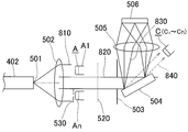
- FIG. 1 It is a figure which shows an example of the basic structure of the spectroscopic measuring instrument which concerns on one Embodiment of this invention. It is a figure which shows the detailed structure of the spectroscopic part in the spectroscopic measuring instrument of FIG. It is a schematic view when the diffraction grating is seen from the front side of the diaphragm in the spectroscopic part of FIG. It is a top view of the spectroscopic part of FIG. It is a figure which shows the arrangement example of the auxiliary sensor at the time of the correction processing which concerns on 1st Embodiment. It is a figure which shows the flowchart of the correction process which concerns on 1st Embodiment.
- FIG. 1 is a diagram showing a basic configuration of a spectroluminometer, which is a spectrophotometer according to an embodiment of the present invention.
- the spectroscopic measuring instrument 1 includes a light receiving optical system 100, an observation optical system 200, a measurement optical system 300, a processing circuit 600, and a correction unit 700, and the measurement optical system 300 further includes a correction unit 700. It includes a light guide unit 400 and a spectroscopic unit 500.
- the light receiving optical system 100 receives the light beam 3 from the object 2 to be measured, which is a light source, and guides the light beam 3 to the light guide unit 400 and the observation optical system 200 of the measurement optical system 300, and the light beam from the object 2 to be measured.
- An objective lens 101 that collects light 3 an aperture diaphragm 102 for regulating the amount of measured light arranged behind the objective lens 101 (front in the traveling direction of the light beam 3), and an aperture mirror further arranged behind the aperture diaphragm 102. It is equipped with 103.
- the aperture mirror 103 is a mirror that is arranged in the incident optical path of the light flux 3 to the light guide unit 400 and has an aperture through which the light flux 3 focused by the objective lens 101 passes.
- the light beam from the objective lens 101 passes through the aperture of the aperture mirror 103 and goes straight to the light guide portion 400 in the subsequent stage, but the light beam outside the light measurement area is the aperture. It is reflected by the mirror 103 and guided to the pupil of the user through a lens group including the reflection mirror 201 and the observation relay lens 202 in the observation optical system 200.
- the user visually recognizes the object 2 to be measured and the index circle (the area that is not reflected by the aperture mirror and appears to be black to the user) from the observation optical system 200, and performs measurement positioning and focusing. Focusing focuses on the aperture mirror position by moving all or part of the lens group of the objective lens 101.
- the aperture angle (F number) of the measurement light does not change even if the aperture diaphragm 102 is focused.
- the hole size of the aperture mirror 103 may be changed manually or automatically.
- the measurement angle (measurement size) can be changed by changing the hole size.
- the light guide unit 400 in the measurement optical system 300 guides the light beam passing through the aperture of the aperture mirror 103 to the condensing lens 401 and the light beam passing through the condensing lens 401 to the incident slit 501 of the spectroscopic unit 500.
- a shining bundle fiber 402 is provided, and in this embodiment, the outlet of the bundle fiber 402 and the incident slit 501 are shared as an incident portion.
- the bundle fiber 402 and the incident slit 501 may be at least one of them.
- the spectroscopic unit 500 in the measurement optical system 300 has a collimator lens 502 that makes the light beam incident from the incident slit 501 substantially parallel light, and a rectangular opening 503a arranged behind the parallel light from the collimator lens 502.
- the aperture 503 regulates the amount of parallel light from the collimator lens 502 according to the size of the diffraction grating 504, and the imaging lens 505 images the light rays dispersed in wavelength by the diffraction grating 504 on the main sensor 506. It is what makes you.
- the diaphragm 503 is highly reliable because it is resistant to changes in the environment and changes over time, and is not dependent on the wavelength of light or the inclination (angle of light incident).
- the main sensor 506 includes, but is not limited to, a line sensor, and can receive light in a wavelength range of, for example, 380 to 780 nm.
- an optical filter which is one of the received light amount adjusting members as an optical system component, for example, an infrared light cut filter 510 for cutting infrared light and an infrared light cut filter 510 behind the infrared light cut filter 510 are also received light.
- a dimming member 520 which is one of the light amount adjusting members, is arranged. Only one of the infrared light cut filter 510 and the dimming member 520 may be arranged, or both may not be arranged. Further, the number of dimming members 520 may be one, or a plurality of dimming members 520 may be arranged in the optical path at the same time.
- the dimming member 520 is used to enable measurement with a wide dynamic range, as described in the background technology, and is composed of an ND filter, a liquid crystal shutter, a diffuser, and the like.
- the dimming member 520 is driven by the drive unit 521 so as to be insertable and retractable into the optical path, and is inserted into the optical path only when necessary to allow the light to be measured from the collimator lens 502 to pass through. It has become.
- the spectroscopic unit 500 is provided with one or a plurality of auxiliary sensors A, B, and C composed of light receiving sensors.
- one or a plurality of sensors are collectively referred to as an auxiliary sensor A, an auxiliary sensor B, and an auxiliary sensor C according to the arrangement position of the auxiliary sensors.
- auxiliary sensors A1 to An When it is necessary to refer to a plurality of auxiliary sensors, they are described as auxiliary sensors A1 to An, auxiliary sensors B1 to Bn, and auxiliary sensors C1 to Cn.
- auxiliary sensors A, B, and C highly reliable sensors such as silicon photodiodes (SPDs) that are resistant to changes in environmental temperature and aging are used.
- SPDs silicon photodiodes
- the auxiliary sensors A, B, and C are for correcting the output value of the main sensor 506 based on the output value of the auxiliary sensor, and are incident on the spectroscopic unit 500 from the light guide unit 400 and received by the main sensor 506.
- the light has the same conditions as the light to be measured, but is arranged in the optical path of the luminous flux that does not reach the main sensor 506.
- one or a plurality of auxiliary sensors A are arranged between the collimator lens 502 and the infrared light cut filter 510, and one or a plurality of auxiliary sensors A are arranged between the dimming member 520 and the aperture 503.
- Auxiliary sensor B is arranged.
- the light beam incident on the spectroscopic unit 500 is parallel to the collimator lens 502 and irradiates the diffraction grating 504.
- the diffraction grating 504 is tilted with respect to the optical axis of the collimator lens 502, the light passing through the collimator lens 502.
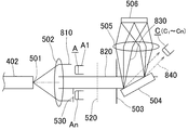
- auxiliary sensors A and B are arranged at positions where the light flux shaded by the diaphragm 503, that is, the light flux that is not used for the measurement by the main sensor 506 and is wasted can be received. Further, as shown in FIGS.
- one or a plurality of auxiliary sensors C may be arranged at positions where the 0th order light 840 diffracted by the diffraction grating 504 can be received.
- the received light data (diffraction-1st order light 830) and the diffraction 0th order light 840 by the main sensor 506 are ordered divided by the diffraction grating 504, and have the same luminous flux under the same conditions (the characteristics depending on the object 2 to be measured are the same). is there.
- Diffraction-1st order light 830 is acquired as spectroscopic data, but other orders are not used for measurement.
- the auxiliary sensor C receives the light flux that is shielded and is wasted.
- the diffraction 0th order light 840 has information on all wavelengths in the measurement wavelength range of 380 to 780 nm, and has a strong light intensity.
- auxiliary sensors A, B, and C are illustrated at three locations as shown in FIGS. 2 and 4, it is not necessary to arrange them at all positions, and the correction processing is performed as in the embodiment described later. You can place it in the required position.
- auxiliary sensors A1 to An, B1 to Bn, and C1 to Cn are used. It may be used to share the range range with each auxiliary sensor.
- a plurality of each is located between the collimator lens 502 and the infrared light cut filter 510, and between the dimming member 520 and the aperture 503, around the optical path of the light to be measured 820.
- Auxiliary sensors A1 to An and B1 to Bn are arranged respectively.
- auxiliary sensors A1 to An and B1 to Bn may be combined with auxiliary sensors C1 to Cn at a position where the 0th order light of diffraction 840 can be received.
- auxiliary sensors A, B, and C in order to control the amount of light received by each of the auxiliary sensors A, B, and C, as shown in FIG. 2, a mechanical diaphragm member 530 and an optical filter (not shown) are arranged in front of the auxiliary sensors A, B, and C. You may.
- the processing circuit 600 shown in FIG. 1 is a circuit that AD-converts the light-receiving data by the main sensor 506 and the light-receiving data by the auxiliary sensors A, B, and C, and the correction unit 700 outputs the auxiliary sensors A, B, and C.
- the output value of the main sensor 506 is corrected based on the value. The correction is performed so that the light receiving intensity value calculated from the output value of the main sensor 506 is the same as the light receiving intensity value calculated from the output values of the auxiliary sensors A, B, and C.
- the auxiliary sensor A is arranged in front of the infrared light cut filter 510, in other words, between the collimator lens 502 and the infrared light cut filter 510.
- the presence or absence of the dimming member 520 does not matter, but it is not considered to be this embodiment.
- One auxiliary sensor A may be used, or a plurality of auxiliary sensors A1 to An corresponding to the dynamic range may be used as in this embodiment.
- Auxiliary sensors A1 to An are equipped with an optical filter, and the light receiving sensitivity is set to the standard luminosity factor (V ⁇ ) in order to facilitate the calculation.
- the sensitivity may be other than the standard luminosity factor (V ⁇ ), or the optical filter may not be provided. It also has a table of the light receiving value and the brightness value (Lv) of the auxiliary sensor A.
- the auxiliary sensor Ax which is one of the auxiliary sensors A1 to An, acquires the absolute value of the brightness and corrects the level of the output value of the main sensor 506.
- the auxiliary sensor Ax and the main sensor 506 simultaneously receive and measure the luminous flux.
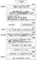
- FIG. 6 shows a flowchart of the measurement procedure.
- step S101 the light receiving data of the plurality of auxiliary sensors A1 to An is AD-converted by the processing circuit 600 to acquire the measurement data (light receiving data).
- step S102 the auxiliary sensor Ax having the optimum sensitivity is selected from the plurality of auxiliary sensors A1 to An, and the approximate brightness value (Lv0) of the object 2 to be measured is calculated from the output value of the auxiliary sensor Ax.
- the approximate brightness value (Lv0) is calculated by obtaining the brightness value corresponding to the output value of the auxiliary sensor Ax from the table of the output value of the auxiliary sensor Ax and the brightness value (Lv).
- the auxiliary sensor Ax to be used in this measurement is determined from the auxiliary sensors A1 to An. Normally, the selected auxiliary sensor Ax is also used in this measurement. Further, the measurement time (accumulation time) of the main sensor 506 and the auxiliary sensor Ax in this measurement is determined.
- step S103 the main measurement is performed in step S103. Specifically, the output value of the main sensor 506 and the output value of the auxiliary sensor Ax are acquired at the same time.
- step S104 the brightness (Lv1) of the object to be measured is calculated from the output value of the auxiliary sensor Ax. The calculation is performed based on the table of the output value and the brightness value of the auxiliary sensor Ax.
- step S105 spectral radiance data is calculated from the output value of the main sensor 506.
- the horizontal axis of the spectral radiance data is calculated from the pixel and wavelength table, and the vertical axis is calculated from the output value and spectral radiance table.
- the brightness (Lv2) is calculated from the calculated spectral radiance data.
- the output value of the main sensor 506 is corrected based on the output value of the auxiliary sensor Ax arranged in front of the infrared light cut filter 510, it exists behind the auxiliary sensor 506. Even if the transmittance of the infrared light cut filter 510 is changed due to environmental conditions, deterioration over time, etc., or even if the accuracy of the main sensor 506 is changed, it is properly corrected and the accuracy is high. Measurements can be made. Moreover, since the auxiliary sensor A is arranged in the optical path of the light flux that does not reach the main sensor 506, the output value of the main sensor 506 can be corrected without affecting the measurement by the main sensor 506.
- the first embodiment may be applied. If the dimming member 520 is present, the transmittance of the dimming member 520 is also compensated.
- the auxiliary sensor A is arranged in front of the dimming member 520 that is driven so as to be inserted and retracted with respect to the optical path of the light to be measured 820.
- the number of auxiliary sensors A may be one, or a plurality of auxiliary sensors A1 to An corresponding to the dynamic range may be used as in this embodiment.
- the presence or absence of the infrared light cut filter 510 does not matter, but it is not considered to be this embodiment.
- the auxiliary sensor A is equipped with an optical filter, and the light receiving sensitivity is set to the standard luminosity factor (V ⁇ ) in order to facilitate the calculation.
- the sensitivity may be other than the standard luminosity factor (V ⁇ ), or the optical filter may not be provided. It also has a table of the light receiving value and the brightness value (Lv) of the auxiliary sensor A.
- the auxiliary sensor A acquires the absolute value of the brightness and corrects the level of the output value of the main sensor.
- the auxiliary sensor A and the main sensor 506 simultaneously receive and measure the luminous flux.
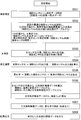
- FIG. 8 shows a flowchart of the measurement procedure.
- the pre-measurement is performed with the dimming member 520 retracted from the optical path of the light to be measured 820. That is, in step S201, the light receiving data of the plurality of auxiliary sensors A1 to An is AD-converted by the processing circuit 600 to acquire the measurement data.
- step S202 the auxiliary sensor Ax having the optimum sensitivity is selected from the plurality of auxiliary sensors A1 to An, and the approximate brightness value (Lv0) of the object 2 to be measured is calculated from the output value of the auxiliary sensor Ax.
- the approximate brightness value (Lv0) is calculated by obtaining the brightness value corresponding to the output value of the auxiliary sensor Ax from the table of the output value of the auxiliary sensor Ax and the brightness value (Lv). Further, from the calculated approximate brightness value (Lv0), whether or not the dimming member 520 is used in the main measurement and the number of the dimming members 520 to be used are determined, and the auxiliary sensors A1 to An are used in the main measurement. Auxiliary sensor Ax to be used is determined. Normally, the selected auxiliary sensor Ax is also used in this measurement. Further, the measurement time (accumulation time) of the main sensor 506 and the auxiliary sensor Ax in this measurement is determined.
- step S204 the process proceeds to step S204 after inserting the determined number of dimming members 520 into the optical path in step S203.
- step S204 the output value of the main sensor 506 and the output value of the auxiliary sensor Ax are acquired at the same time.
- steps S205 to S208 and the result output processing of step S209 are performed. These processes are the correction calculation processing of steps S104 to S107 of FIG. 6 and the result output processing of step S108 described in the first embodiment. Since it is the same as, the description is omitted.
- the accuracy change of the main sensor 506 can be compensated and the dimming member 520 is inserted in the optical path.
- the infrared cut filter 510 is present behind the auxiliary sensor Ax, it is possible to compensate for the change in the transmittance of the infrared cut filter 510 and the change in the transmittance of the dimming member 520.
- an auxiliary sensor is located behind the dimming member 520 that is driven so as to be inserted and retracted with respect to the optical path of the light to be measured 820, in other words, between the dimming member 520 and the aperture 503.
- B is arranged or an auxiliary sensor C for receiving the diffraction 0th order light 840 is arranged, but in this example, the auxiliary sensor B is used.
- the number of auxiliary sensors B may be one, or a plurality of auxiliary sensors B1 to Bn corresponding to the dynamic range may be used as in this embodiment.
- the presence or absence of the infrared light cut filter 510 does not matter, but it is not considered to be this embodiment.
- the auxiliary sensor B is equipped with an optical filter, and the light receiving sensitivity is set to the standard luminosity factor (V ⁇ ) in order to facilitate the calculation.
- the sensitivity may be other than the standard luminosity factor (V ⁇ ), or the optical filter may not be provided. It also has a table of the light receiving value and the brightness value (Lv) of the auxiliary sensor B.
- the auxiliary sensor B acquires the absolute value of the brightness and corrects the level of the output value of the main sensor 506.
- the output value of the main sensor 506 is acquired with the dimming member 520 inserted in the optical path of the light to be measured 820, and the output value of the auxiliary sensor B is obtained with the dimming member 520 retracted from the optical path. get.
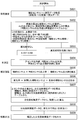
- FIG. 10 shows a flowchart of the measurement procedure.
- the pre-measurement is performed with the dimming member 520 retracted from the optical path of the light to be measured 820. That is, in step S301, the light receiving data of the plurality of auxiliary sensors B1 to Bn is AD-converted by the processing circuit 600 to acquire the measurement data. Next, in step S302, the auxiliary sensor Bx having the optimum sensitivity is selected from the plurality of auxiliary sensors B1 to Bn, and the approximate brightness value (Lv0) of the object 2 to be measured is calculated from the output value of the auxiliary sensor Bx.
- the approximate brightness value (Lv0) is calculated by obtaining the brightness value corresponding to the output value of the auxiliary sensor Bx from the table of the output value of the auxiliary sensor Bx and the brightness value (Lv). Further, from the calculated approximate brightness value (Lv0), whether or not the dimming member 520 is used in the main measurement and the number of the dimming members 520 to be used are determined, and the auxiliary sensors B1 to Bn are used in the main measurement. Auxiliary sensor Bx to be used is determined. Normally, the selected auxiliary sensor Bx is also used in this measurement. Further, the measurement time (accumulation time) of the main sensor 506 and the auxiliary sensor Bx in this measurement is determined.
- step S308 the output value of the main sensor 506 and the output value of the auxiliary sensor Bx are simultaneously acquired in step S303 while the dimming member 520 is retracted from the optical path, and then the step Proceed to S308.
- the determined number of dimming members 520 are inserted into the optical path of the light to be measured 820 in step S304, and then the output value of the main sensor 506 is set in step S305. get.
- the output value of the auxiliary sensor Bx is acquired in step S307, and the process proceeds to step S308.
- step S311 the correction calculation process of steps S308 to S311 and the result output process of step S312 are performed.
- the output value of the auxiliary sensor Bx is used to calculate the brightness (Lv1) of the object 2 to be measured in step S308. Since it is the same as the correction calculation process of steps S104 to S107 and the result output process of step S108 described in the first embodiment, the description thereof will be omitted.
- the auxiliary sensor B is arranged behind the dimming member 520, and the output value of the auxiliary sensor B acquired in a state where the dimming member 520 is retracted from the optical path of the light to be measured 820 is used. Since the output value of the main sensor 506 acquired while the dimming member 520 is inserted in the optical path is corrected, it is possible to compensate for the change in the transmittance of the dimming member 520 and the change in the accuracy of the main sensor 506, and the accuracy is high. Measurements can be made. If the infrared light cut filter 510 is present, it can be compensated for by including a change in the transmittance of the infrared light cut filter 510.
- the auxiliary sensor B is located behind the dimming member 520 driven so as to be able to advance and retreat with respect to the optical path of the light to be measured 820, in other words, between the dimming member 520 and the aperture 503.
- an auxiliary sensor C that receives the 0th-order diffraction light 840 is placed, but in this example, the auxiliary sensor C that receives the 0th-order diffraction light is used.
- the number of auxiliary sensors C may be one, or a plurality of auxiliary sensors C1 to Cn corresponding to the dynamic range may be used as in this embodiment.
- auxiliary sensors A arranged in front of the dimming member 520 are also used.
- the presence or absence of the infrared light cut filter 510 does not matter, but it is not considered to be this embodiment.
- Each of the auxiliary sensors C1 to Cn and A is equipped with an optical filter, and the light receiving sensitivity is set to the standard luminosity factor (V ⁇ ) in order to facilitate the calculation.
- the sensitivity may be other than the standard luminosity factor (V ⁇ ), or the optical filter may not be provided. It also has a table of the light receiving value and the brightness value (Lv) of the auxiliary sensor C.
- the auxiliary sensor C acquires the absolute value of the brightness and corrects the level of the output value of the main sensor 506. In addition, the auxiliary sensor A corrects the time change.
- FIG. 12 shows a flowchart of the measurement procedure.
- the pre-measurement is performed with the dimming member 520 retracted from the optical path of the light to be measured 820. That is, in step S401, the light receiving data of the plurality of auxiliary sensors C1 to Cn are AD-converted by the processing circuit 600 to acquire the measurement data.
- the auxiliary sensor Cx having the optimum sensitivity is selected from the plurality of auxiliary sensors C1 to Cn, and the approximate brightness value (Lv0) of the object 2 to be measured is calculated from the output value of the auxiliary sensor Cx.
- the approximate brightness value (Lv0) is calculated by obtaining the brightness value corresponding to the output value of the auxiliary sensor Cx from the table of the output value of the auxiliary sensor Cx and the brightness value (Lv). Further, from the calculated approximate brightness value (Lv0), whether or not the dimming member 520 is used in the main measurement and the number of the dimming members 520 to be used are determined, and the auxiliary sensors A1 to An are used in the main measurement. The auxiliary sensor Ax to be used is determined, and the auxiliary sensor Cx is determined from the auxiliary sensors C1 to Cn. Normally, the selected auxiliary sensor Cx is also used in this measurement. Further, the measurement time (accumulation time) of the main sensor 506, the auxiliary sensor Ax, and the auxiliary sensor Cx in this measurement is determined.
- step S403 the output value of the main sensor 506 and the output value of the auxiliary sensor Cx are simultaneously set in step S403 while keeping the dimming member 520 retracted from the optical path of the light to be measured 820.
- step S408 the determined number of dimming members 520 are inserted into the optical path in step S404, and then the output value of the main sensor 506 and the output of the auxiliary sensor Ax are output in step S405.
- the value a1 is acquired at the same time.
- step S406 After the dimming member 520 is retracted from the optical path in step S406, the output value a2 of the auxiliary sensor Ax and the output value b of the auxiliary sensor Cx are simultaneously acquired in step S407, and the process proceeds to step S408.
- step S408 the brightness (Lv1) of the object to be measured is calculated from the output value of the auxiliary sensor Cx. The calculation is performed based on the table of the output value and the brightness value of the auxiliary sensor Cx.
- step S411 the spectral radiance data is calculated from the output value of the main sensor 506, and the brightness (Lv2) is calculated from the calculated spectral radiance data.
- step S414 the spectral radiance data is corrected by each correction coefficient over all wavelengths. Then, in step S415, the corrected spectral radiance data is output.
- the dimming member 520 is acquired in the state of being inserted into the optical path by the output value of the auxiliary sensor Cx acquired in the state of being retracted from the optical path of the light to be measured 820.
- the output value of the auxiliary sensor 506 is corrected, and the change in the amount of light over time due to the difference between the acquisition timing of the auxiliary sensor Cx and the acquisition timing of the output value of the main sensor 506 is measured at each timing. Since it is corrected by the time difference count (temporal change rate of light amount) which is the ratio of the values a1 and a2, more accurate measurement can be performed.
- the infrared cut filter 510 is present behind the auxiliary sensor Ax, it is possible to compensate for the change in the transmittance of the infrared cut filter 510 and the change in the transmittance of the dimming member 520.
- an auxiliary sensor A is arranged between the collimator lens 502 and the infrared light cut filter 510, and one auxiliary sensor B is arranged behind the infrared light cut filter 510. ..
- the presence or absence of the dimming member 520 does not matter, but it is not considered to be this embodiment.
- the number of auxiliary sensors A may be one, or a plurality of auxiliary sensors A1 to An corresponding to the dynamic range may be used as in this embodiment. Since the rear auxiliary sensor B has passed through the dimming member 520, the one set to an appropriate amount of light is used.
- auxiliary sensor B instead of the auxiliary sensor B, one auxiliary sensor C that receives the diffraction 0th order light may be used.
- Auxiliary sensors A1 to An are equipped with an optical filter, and the light receiving sensitivity is set to the standard luminosity factor (V ⁇ ) in order to facilitate the calculation.
- the sensitivity may be other than the standard luminosity factor (V ⁇ ), or the optical filter may not be provided. It also has a table of the light receiving value and the brightness value (Lv) of the auxiliary sensor A. Further, at the time of shipment from the factory, a reference value (referred to as a reference auxiliary sensor ratio) of the output value ratio of the auxiliary sensor A and the auxiliary sensor B (when the auxiliary sensor C is used, the auxiliary sensor C) is stored.
- V ⁇ standard luminosity factor
- Lv brightness value
- the transmittance of the infrared light cut filter 510 is set from the factory default based on the reference auxiliary sensor ratio of the auxiliary sensors A1 to An in front of the infrared light cut filter 510 and the auxiliary sensor B in the rear. It compensates for change.
- FIG. 14 shows a flowchart of the measurement procedure.
- step S501 the received light data of the plurality of auxiliary sensors A1 to An is AD-converted by the processing circuit 600 to acquire the measurement data.
- step S502 the auxiliary sensor Ax having the optimum sensitivity is selected from the plurality of auxiliary sensors A1 to An, and the approximate brightness value (Lv0) of the object 2 to be measured is calculated from the output value of the auxiliary sensor Ax.
- the approximate brightness value (Lv0) is calculated by obtaining the brightness value corresponding to the output value of the auxiliary sensor Ax from the table of the output value of the auxiliary sensor Ax and the brightness value (Lv).
- the auxiliary sensor Ax to be used in this measurement is determined from the auxiliary sensors A1 to An. Normally, the selected auxiliary sensor Ax is also used in this measurement. Further, the measurement time (accumulation time) of the main sensor 506, the auxiliary sensor Ax, and the auxiliary sensor B in this measurement is determined.
- step S503 the main measurement is performed in step S503. Specifically, the output values of the main sensor 506, the auxiliary sensor Ax, and the auxiliary sensor B are acquired at the same time.
- spectral radiance data is calculated from the output value of the main sensor 506.
- the horizontal axis of the spectral radiance data is calculated from the pixel and wavelength table, and the other and axes are calculated from the output value and spectral radiance table.
- the brightness (Lv2) is calculated from the calculated spectral radiance data.
- step S507 the spectral radiance data is corrected with the rate of change calculated in step S505 over all wavelengths. Then, in step S108, the corrected spectral radiance data is output.
- the transmittance of the infrared light cut filter 510 and the like from the factory shipment are based on the output values of the auxiliary sensor Ax in front of the infrared light cut filter 510 and the auxiliary sensor B in the rear. Since the change is corrected by the rate of change and the output value of the main sensor 506 is corrected by this rate of change, the transmittance of the infrared light cut filter 510 and the like are changed due to environmental conditions, deterioration over time, and the like. However, it is possible to perform highly accurate measurement. When the infrared light cut filter 510 does not exist and the fixed dimming member 520 is provided, the change in the transmittance of the dimming member 520 can be compensated.
- both the infrared light cut filter 510 and the dimming member 520 are present between the auxiliary sensors A1 to An and the auxiliary sensor B, the entire infrared light cut filter 510 and the dimming member 520 are combined. It is possible to compensate for changes in transmittance and the like.
- the auxiliary sensor A is arranged in front of the dimming member 520 that is driven so as to advance and retreat with respect to the optical path of the light to be measured 820 of the light to be measured 820, and further, the diffraction 0th order One auxiliary sensor C that receives light 840 is arranged.
- the number of auxiliary sensors A may be one, or a plurality of auxiliary sensors A1 to An corresponding to the dynamic range may be used as in this embodiment. Since the auxiliary sensor C has passed through the dimming member 520, the one set to an appropriate amount of light is used.
- the auxiliary sensor B arranged between the dimming member 520 and the aperture 503 may be used.
- the presence or absence of the infrared light cut filter 510 does not matter, but it is not considered to be this embodiment.
- the auxiliary sensor A is equipped with an optical filter, and the light receiving sensitivity is set to the standard luminosity factor (V ⁇ ) in order to facilitate the calculation.
- the sensitivity may be other than the standard luminosity factor (V ⁇ ), or the optical filter may not be provided. It also has a table of the light receiving value and the brightness value (Lv) of the auxiliary sensor A. Further, at the time of shipment from the factory, a reference value (reference auxiliary sensor ratio) of the output value ratio of the auxiliary sensors A and C is stored.
- the change in the transmittance of the dimming member 520 from the factory is compensated based on the reference auxiliary sensor ratio of the auxiliary sensors A1 to An in front of the dimming member 520 and the auxiliary sensor C in the rear. It is a thing.
- FIG. 16 shows a flowchart of the measurement procedure.
- step S601 the light receiving data of the plurality of auxiliary sensors A1 to An is AD-converted by the processing circuit 600 to acquire the measurement data.
- step S602 the auxiliary sensor Ax having the optimum sensitivity is selected from the plurality of auxiliary sensors A1 to An, and the approximate brightness value (Lv0) of the object 2 to be measured is calculated from the output value of the auxiliary sensor Ax.
- the approximate brightness value (Lv0) is calculated by obtaining the brightness value corresponding to the output value of the auxiliary sensor Ax from the table of the output value of the auxiliary sensor Ax and the brightness value (Lv).
- the auxiliary sensors A1 to An are used in the main measurement.
- Auxiliary sensor Ax to be used is determined. Normally, the selected auxiliary sensor Ax is also used in this measurement. Further, the measurement time (accumulation time) of the main sensor 506, the auxiliary sensor Ax, and the auxiliary sensor C in this measurement is determined.
- step S604 After inserting the determined number of dimming members 520 into the optical path in step S603.
- step S604 the output values of the main sensor 506, the auxiliary sensor Ax, and the auxiliary sensor C are acquired at the same time.
- step S605 to S608 the correction calculation process of steps S605 to S608 and the result output process of step S609 are performed.
- the output value of the auxiliary sensor C is used instead of the auxiliary sensor B to calculate the auxiliary sensor ratio in step S605. Since it is the same as the correction calculation process of steps S504 to S507 of FIG. 11 and the result output process of step S508 described in the fifth embodiment, the description thereof will be omitted.
- the transmittance of the dimming member 520 and the like are changed from the factory default based on the output values of the auxiliary sensor Ax arranged in front of the dimming member 520 and the auxiliary sensor C in the rear. Is corrected by the rate of change, and the output value of the main sensor 506 is corrected by this rate of change. Therefore, even if the transmittance of the dimming member 520 changes due to environmental conditions, deterioration over time, etc., the accuracy is correct. High measurement can be performed.
- the change in the transmittance of the infrared light cut filter 510 and the dimming member 520 combined is compensated. Can be done.
- the auxiliary sensor B is arranged behind the dimming member 520 that is driven so as to advance and retreat with respect to the optical path of the light to be measured 820.
- the number of auxiliary sensors B may be one, or a plurality of auxiliary sensors B1 to Bn corresponding to the dynamic range may be used as in this embodiment.
- the auxiliary sensor C that receives the diffraction 0th order light 840 may be used.
- the presence or absence of the infrared light cut filter 510 does not matter, but it is not considered to be this embodiment.
- the auxiliary sensor B is equipped with an optical filter, and the light receiving sensitivity is set to the standard luminosity factor (V ⁇ ) in order to facilitate the calculation.
- the sensitivity may be other than the standard luminosity factor (V ⁇ ), or the optical filter may not be provided. It also has a table of the light receiving value and the brightness value (Lv) of the auxiliary sensor B.
- the dimming rate of the dimming member 520 is obtained and corrected from the output value ratio of the auxiliary sensor B when the dimming member 520 is inserted into the optical path and when it is retracted.
- FIG. 18 shows a flowchart of the measurement procedure.
- step S701 the light receiving data of the plurality of auxiliary sensors B1 to Bn is AD-converted by the processing circuit 600 to acquire the measurement data.
- step S702 the auxiliary sensor Bx having the optimum sensitivity is selected from the plurality of auxiliary sensors B1 to Bn. Further, from the output value of the auxiliary sensor Bx, whether or not the dimming member 520 is used in the main measurement and the number of the dimming members to be used are determined, and the dimming member used in the main measurement from the auxiliary sensors B1 to Bn.
- the auxiliary sensor Bx when there is and the auxiliary sensor By when there is no dimming member are determined.
- the auxiliary sensor Bx and the auxiliary sensor By may be the same. Further, the measurement time (accumulation time) of the main sensor 506, the auxiliary sensor Bx, and the auxiliary sensor By in this measurement is determined.
- steps S103 to S108 of FIG. 6 are performed while keeping the dimming member 520 retracted from the optical path of the light to be measured 820.
- the "auxiliary sensor Ax" in steps S103 and S104 is replaced with the "auxiliary sensor Bx”.
- step S704 the determined number of dimming members 520 are inserted into the optical path in step S704, and then the output value of the main sensor 506 and the output of the auxiliary sensor Bx in step S705. Get the value ⁇ at the same time.
- step S706 the dimming member 520 is retracted from the optical path in step S706, the output value ⁇ of the auxiliary sensor By is acquired in step S707.
- step S709 spectral radiance data is calculated from the output value of the main sensor 506. Then, the brightness (Lv2) is calculated from the calculated spectral radiance data.
- step S710 the spectral radiance data is corrected over all wavelengths with the dimming rate calculated in step S708. Then, in step S711, the corrected spectral radiance data is output.
- the dimming rate of the dimming member 520 is obtained based on the output values of the auxiliary sensors Bx and By arranged behind the dimming member 520, and the change in the transmittance and the like is reduced. It is corrected by the light rate, and the output value of the main sensor is corrected by this dimming rate. Therefore, even if the transmittance of the dimming member 520 changes due to environmental conditions, deterioration over time, etc. High measurements can be made.
- the auxiliary sensor B is arranged between the dimming member 520 and the diaphragm 503, which are driven so as to advance and retreat with respect to the optical path of the light to be measured 820, or the diffraction 0th order light 840.
- the auxiliary sensor C that receives light is arranged, in this example, it is assumed that the auxiliary sensor C that receives the diffraction 0th order light 840 is used.
- the number of auxiliary sensors C may be one, or a plurality of auxiliary sensors C1 to Cn corresponding to the dynamic range may be used as in this embodiment.
- auxiliary sensors A1 to An arranged in front of the dimming member 520 are also used.
- the presence or absence of the infrared light cut filter 510 does not matter, but it is not considered to be this embodiment.
- the auxiliary sensor C is equipped with an optical filter, and the light receiving sensitivity is set to the standard luminosity factor (V ⁇ ) in order to facilitate the calculation.
- the sensitivity may be other than the standard luminosity factor (V ⁇ ), or the optical filter may not be provided. It also has a table of the light receiving value and the brightness value (Lv) of the auxiliary sensor C.
- the dimming rate of the dimming member 520 is obtained and corrected from the output value ratio of the auxiliary sensor C when the light to be measured 820 is inserted into the optical path and when the light is retracted. ..
- the auxiliary sensor A corrects the time change.
- FIG. 20 shows a flowchart of the measurement procedure.
- the pre-measurement is performed with the dimming member 520 retracted from the optical path of the light to be measured 820. That is, in step S801, the light receiving data of the plurality of auxiliary sensors C1 to Cn is AD-converted by the processing circuit 600 to acquire the measurement data.
- the auxiliary sensor Cx having the optimum sensitivity is selected from the plurality of auxiliary sensors C1 to Cn. Further, from the output value of the auxiliary sensor Cx, whether or not the dimming member 520 is used in the main measurement and the number of the dimming members 520 are used, and the auxiliary sensor Ax used in the main measurement is selected from the auxiliary sensors A1 to An.
- the auxiliary sensor Cx when the dimming member is present and the auxiliary sensor Cy when the dimming member is not used are determined.
- the auxiliary sensor Cx and the auxiliary sensor Cy may be the same. Further, the measurement time (accumulation time) of the main sensor 506, the auxiliary sensor Ax, the auxiliary sensor Cx, and the auxiliary sensor Cy in this measurement is determined.
- the main measurement is performed.
- the processes of steps S103 to S108 of FIG. 6 are performed while keeping the dimming member 520 retracted from the optical path of the light to be measured 820.
- the "auxiliary sensor Ax" in steps S103 and S104 is replaced with the "auxiliary sensor Cx".
- the output value of the main sensor 506 and the auxiliary sensor Ax in step S805 are acquired at the same time.
- the output value b of the auxiliary sensor Ax and the output value ⁇ of the auxiliary sensor Cy are simultaneously acquired in step S807.
- step S810 spectral radiance data is calculated from the output value of the main sensor 506. Then, the brightness (Lv2) is calculated from the calculated spectral radiance data.
- step S811 the spectral radiance data is corrected over all wavelengths with the dimming rate calculated in step S809. Then, in step S812, the corrected spectral radiance data is output.
- the dimming rate of the dimming member 520 is obtained based on the output values of the auxiliary sensors Cx and Cy arranged behind the dimming member 520, and the change in the transmittance and the like is reduced. It is corrected by the light rate, and the output value of the main sensor 506 is corrected by this dimming rate. Therefore, even if the transmittance of the dimming member 520 changes due to environmental conditions, deterioration over time, etc., the accuracy is correct. High measurement can be performed. Moreover, since the time difference coefficient, which is the ratio of the output values a and b of the auxiliary sensor Ax measured at different timings, corrects the change in the amount of light with time, the dimming rate can be measured with higher accuracy.
- the present invention can be used when measuring the brightness and chromaticity of a light source, the spectral reflectance of an object, the color value, and the like.
- Spectral measuring instrument 1 Spectral measuring instrument 2 Object to be measured 3 Light to be measured 100 Light receiving optical system 200 Observation optical system 300 Measuring optical system 400 Light guide part 402 Bundle fiber 500 Spectral part 501 Incident slit 502 Collimeter lens 503 Aperture 503a Opening 504 Diffraction lattice 506 Sensor 510 Infrared light cut filter 520 Dimming member 600 Processing circuit 700 Correction unit 810 Corimeter lens passing light 820 Measured light 840 Diffraction 0th order light A to C, A1 to An, B1 to Bn, C1 to Cn Auxiliary sensor
Landscapes
- Physics & Mathematics (AREA)
- Spectroscopy & Molecular Physics (AREA)
- General Physics & Mathematics (AREA)
- Health & Medical Sciences (AREA)
- Life Sciences & Earth Sciences (AREA)
- Chemical & Material Sciences (AREA)
- Analytical Chemistry (AREA)
- Biochemistry (AREA)
- General Health & Medical Sciences (AREA)
- Immunology (AREA)
- Pathology (AREA)
- Spectrometry And Color Measurement (AREA)
- Photometry And Measurement Of Optical Pulse Characteristics (AREA)
Priority Applications (3)
| Application Number | Priority Date | Filing Date | Title |
|---|---|---|---|
| JP2021529994A JP7494851B2 (ja) | 2019-07-04 | 2020-06-26 | 分光測定器 |
| US17/620,978 US12104953B2 (en) | 2019-07-04 | 2020-06-26 | Spectrometer |
| CN202080046919.8A CN114026407A (zh) | 2019-07-04 | 2020-06-26 | 分光测定器 |
Applications Claiming Priority (2)
| Application Number | Priority Date | Filing Date | Title |
|---|---|---|---|
| JP2019-125273 | 2019-07-04 | ||
| JP2019125273 | 2019-07-04 |
Publications (1)
| Publication Number | Publication Date |
|---|---|
| WO2021002286A1 true WO2021002286A1 (ja) | 2021-01-07 |
Family
ID=74100276
Family Applications (1)
| Application Number | Title | Priority Date | Filing Date |
|---|---|---|---|
| PCT/JP2020/025177 Ceased WO2021002286A1 (ja) | 2019-07-04 | 2020-06-26 | 分光測定器 |
Country Status (4)
| Country | Link |
|---|---|
| US (1) | US12104953B2 (https=) |
| JP (1) | JP7494851B2 (https=) |
| CN (1) | CN114026407A (https=) |
| WO (1) | WO2021002286A1 (https=) |
Citations (6)
| Publication number | Priority date | Publication date | Assignee | Title |
|---|---|---|---|---|
| JPS6250641A (ja) * | 1985-08-30 | 1987-03-05 | Hitachi Ltd | 吸光光度計を備えた分析装置 |
| JPS63117234A (ja) * | 1986-11-04 | 1988-05-21 | Canon Inc | 光学測定装置 |
| JP2002206967A (ja) * | 2001-01-11 | 2002-07-26 | Minolta Co Ltd | 測光装置および測色装置 |
| JP2013168512A (ja) * | 2012-02-15 | 2013-08-29 | Seiko Instruments Inc | 光検出デバイス及び光検出デバイスの製造方法 |
| JP2016114544A (ja) * | 2014-12-17 | 2016-06-23 | 三井金属計測機工株式会社 | 青果物非破壊糖酸度計及びその使用方法 |
| CN109187369A (zh) * | 2018-08-02 | 2019-01-11 | 佛山市方垣机仪设备有限公司 | 一种应用了联合检测技术的油料检测装置及检测方法 |
Family Cites Families (7)
| Publication number | Priority date | Publication date | Assignee | Title |
|---|---|---|---|---|
| JP4454098B2 (ja) | 2000-03-21 | 2010-04-21 | 株式会社トプコン | 測光装置 |
| JP4089314B2 (ja) | 2002-07-04 | 2008-05-28 | コニカミノルタセンシング株式会社 | 回折手段の0次回折光を利用した分光測定器 |
| JP4642627B2 (ja) | 2005-10-12 | 2011-03-02 | キヤノン株式会社 | 走査光学装置及びそれを用いた画像形成装置 |
| US8735803B2 (en) * | 2009-11-06 | 2014-05-27 | Precision Energy Services, Inc | Multi-channel detector assembly for downhole spectroscopy |
| US8901513B2 (en) * | 2011-03-08 | 2014-12-02 | Horiba Instruments, Incorporated | System and method for fluorescence and absorbance analysis |
| EP3032277B1 (de) * | 2014-12-12 | 2021-04-07 | Leica Geosystems AG | Lasertracker |
| EP3470924A1 (en) * | 2017-10-11 | 2019-04-17 | ASML Netherlands B.V. | Method of optimizing the position and/or size of a measurement illumination spot relative to a target on a substrate, and associated apparatus |
-
2020
- 2020-06-26 JP JP2021529994A patent/JP7494851B2/ja active Active
- 2020-06-26 WO PCT/JP2020/025177 patent/WO2021002286A1/ja not_active Ceased
- 2020-06-26 US US17/620,978 patent/US12104953B2/en active Active
- 2020-06-26 CN CN202080046919.8A patent/CN114026407A/zh active Pending
Patent Citations (6)
| Publication number | Priority date | Publication date | Assignee | Title |
|---|---|---|---|---|
| JPS6250641A (ja) * | 1985-08-30 | 1987-03-05 | Hitachi Ltd | 吸光光度計を備えた分析装置 |
| JPS63117234A (ja) * | 1986-11-04 | 1988-05-21 | Canon Inc | 光学測定装置 |
| JP2002206967A (ja) * | 2001-01-11 | 2002-07-26 | Minolta Co Ltd | 測光装置および測色装置 |
| JP2013168512A (ja) * | 2012-02-15 | 2013-08-29 | Seiko Instruments Inc | 光検出デバイス及び光検出デバイスの製造方法 |
| JP2016114544A (ja) * | 2014-12-17 | 2016-06-23 | 三井金属計測機工株式会社 | 青果物非破壊糖酸度計及びその使用方法 |
| CN109187369A (zh) * | 2018-08-02 | 2019-01-11 | 佛山市方垣机仪设备有限公司 | 一种应用了联合检测技术的油料检测装置及检测方法 |
Also Published As
| Publication number | Publication date |
|---|---|
| US20220357199A1 (en) | 2022-11-10 |
| US12104953B2 (en) | 2024-10-01 |
| JPWO2021002286A1 (https=) | 2021-01-07 |
| CN114026407A (zh) | 2022-02-08 |
| JP7494851B2 (ja) | 2024-06-04 |
Similar Documents
| Publication | Publication Date | Title |
|---|---|---|
| Potanin et al. | Transient Double-beam Spectrograph for the 2.5-m Telescope of the Caucasus Mountain Observatory of SAI MSU | |
| CN106461465B (zh) | 光学特性测定装置以及光学特性测定方法 | |
| JP2011089961A (ja) | 分光器およびそれを備えた測光装置 | |
| US11359966B2 (en) | System, method and apparatus for wide wavelength range imaging with focus and image correction | |
| CN101922968B (zh) | 一种距离误差自动校正亮度计 | |
| US20120105847A1 (en) | Spectrometric measurement system and method for compensating for veiling glare | |
| US12271004B2 (en) | Imager and spot sampler with translatable stage | |
| US20150247798A1 (en) | Optical system and optical quality measuring apparatus | |
| JP7494851B2 (ja) | 分光測定器 | |
| Dittrich et al. | Measurement principle and arrangement for the determination of spectral channel-specific angle dependencies for multispectral resolving filter-on-chip CMOS cameras | |
| KR101239573B1 (ko) | 측광 장치 | |
| CA2775621C (en) | Scanning multispectral telescope comprising wavefront analysis means | |
| US20240393178A1 (en) | Method for calibrating a spectrometer device | |
| KR20240011694A (ko) | 막 두께 측정 장치 및 막 두께 측정 방법 | |
| US8416404B2 (en) | Method and system for measurement and correction of thermally induced changes of boresight, effective focal length, and focus | |
| Breare et al. | The faint object spectrograph for the 2.5-m Isaac Newton Telescope | |
| Plaipichit et al. | Spectroscopy system using digital camera as two dimensional detectors for undergraduate student laboratory | |
| JP7616218B2 (ja) | 変倍対物レンズおよびそれを備える測光測色計 | |
| CN201748974U (zh) | 一种距离误差自动校正亮度计 | |
| RU2025657C1 (ru) | Устройство для контроля толщины пленок многослойного оптического покрытия в процессе его нанесения осаждением в вакуумной камере | |
| CN212459386U (zh) | 一种光学测量仪器 | |
| JPS5839915A (ja) | 光センサ分光感度測定装置 | |
| JP6331986B2 (ja) | 光学特性測定装置 | |
| CN108291839B (zh) | 测定用光学装置 | |
| US20200018649A1 (en) | Imaging Spectrograph Utilizing the Zero Order of the Diffraction Grating |
Legal Events
| Date | Code | Title | Description |
|---|---|---|---|
| 121 | Ep: the epo has been informed by wipo that ep was designated in this application |
Ref document number: 20834951 Country of ref document: EP Kind code of ref document: A1 |
|
| ENP | Entry into the national phase |
Ref document number: 2021529994 Country of ref document: JP Kind code of ref document: A |
|
| NENP | Non-entry into the national phase |
Ref country code: DE |
|
| 122 | Ep: pct application non-entry in european phase |
Ref document number: 20834951 Country of ref document: EP Kind code of ref document: A1 |