WO2021001934A1 - 空調用検出装置、空調制御装置、空調装置、空調システム及び空調方法 - Google Patents
空調用検出装置、空調制御装置、空調装置、空調システム及び空調方法 Download PDFInfo
- Publication number
- WO2021001934A1 WO2021001934A1 PCT/JP2019/026330 JP2019026330W WO2021001934A1 WO 2021001934 A1 WO2021001934 A1 WO 2021001934A1 JP 2019026330 W JP2019026330 W JP 2019026330W WO 2021001934 A1 WO2021001934 A1 WO 2021001934A1
- Authority
- WO
- WIPO (PCT)
- Prior art keywords
- air conditioning
- unit
- antenna
- indoor space
- terminal device
- Prior art date
- Legal status (The legal status is an assumption and is not a legal conclusion. Google has not performed a legal analysis and makes no representation as to the accuracy of the status listed.)
- Ceased
Links
Images



Classifications
-
- F—MECHANICAL ENGINEERING; LIGHTING; HEATING; WEAPONS; BLASTING
- F24—HEATING; RANGES; VENTILATING
- F24F—AIR-CONDITIONING; AIR-HUMIDIFICATION; VENTILATION; USE OF AIR CURRENTS FOR SCREENING
- F24F11/00—Control or safety arrangements
- F24F11/70—Control systems characterised by their outputs; Constructional details thereof
-
- G—PHYSICS
- G01—MEASURING; TESTING
- G01S—RADIO DIRECTION-FINDING; RADIO NAVIGATION; DETERMINING DISTANCE OR VELOCITY BY USE OF RADIO WAVES; LOCATING OR PRESENCE-DETECTING BY USE OF THE REFLECTION OR RERADIATION OF RADIO WAVES; ANALOGOUS ARRANGEMENTS USING OTHER WAVES
- G01S3/00—Direction-finders for determining the direction from which infrasonic, sonic, ultrasonic or electromagnetic waves, or particle emission, not having a directional significance, are being received
- G01S3/02—Direction-finders for determining the direction from which infrasonic, sonic, ultrasonic or electromagnetic waves, or particle emission, not having a directional significance, are being received using radio waves
- G01S3/14—Systems for determining direction or deviation from predetermined direction
- G01S3/16—Systems for determining direction or deviation from predetermined direction using amplitude comparison of signals derived sequentially from receiving antennas or antenna systems having differently-oriented directivity characteristics or from an antenna system having periodically-varied orientation of directivity characteristic
- G01S3/20—Systems for determining direction or deviation from predetermined direction using amplitude comparison of signals derived sequentially from receiving antennas or antenna systems having differently-oriented directivity characteristics or from an antenna system having periodically-varied orientation of directivity characteristic derived by sampling signal received by an antenna system having periodically-varied orientation of directivity characteristic
Definitions
- the present invention relates to an air conditioning detection device, an air conditioning control device, an air conditioning device, an air conditioning system, and an air conditioning method.
- Patent Document 1 discloses an air conditioner that controls air conditioning by specifying an area of an operator of a remote controller based on an image acquired by an imaging device and a signal detected from the remote controller. Specifically, the air conditioner disclosed in Patent Document 1 recognizes the user's face or hand raising motion from the image acquired by the imaging device, and the user is positioned based on the face recognition result or the hand raising hand recognition result. Identify the area.
- Patent Document 1 it is necessary to recognize the face or hand raising motion from the image acquired by the imaging device in order to detect the position information of the user in the indoor space. Therefore, when it is difficult to recognize the user's face or hand raising motion from the image, for example, when the user overlaps with an object existing in the indoor space or an obstacle such as another user, the above-mentioned Patent Document 1
- the technology disclosed in the above cannot accurately detect the user's position information. Under such circumstances, it is required to more accurately detect the user's position information in the indoor space.
- the present invention has been made to solve the above-mentioned problems, and an object of the present invention is to provide an air-conditioning detection device or the like capable of accurately detecting a user's position information in an indoor space.
- the first aspect of the air conditioning detection device is An imaging means that captures the indoor space to be air-conditioned, An antenna that has directivity and receives a signal transmitted from a terminal device existing in the indoor space.
- Rotational drive means for rotating the antenna and
- a direction detecting means for detecting a direction from the antenna to the terminal device based on a change in the intensity of the signal received by the antenna while the antenna is rotating by the rotation driving means.
- Position information detection that detects the position information of the user existing in the indoor space based on the captured image obtained by the imaging means imaging the region in the direction detected by the direction detecting means in the indoor space. Means and.
- the second aspect of the air conditioning detection device is An imaging means that captures the indoor space to be air-conditioned, An antenna that has directivity and transmits a signal to the indoor space, Rotational drive means for rotating the antenna and A direction detecting means for detecting a direction from the antenna to a terminal device existing in the indoor space based on a response to the signal transmitted from the antenna when the antenna is rotated by the rotation driving means.
- Position information detection that detects the position information of the user existing in the indoor space based on the captured image obtained by the imaging means imaging the region in the direction detected by the direction detecting means in the indoor space. Means and.
- the present invention is based on an image taken by detecting a direction from an antenna to a terminal device based on a signal received or transmitted while a directional antenna is rotating and capturing the detected direction in an indoor space.
- the user's position information in the indoor space is detected. Therefore, according to the present invention, the user's position information in the indoor space can be accurately detected.
- FIG. 1 shows an example of an imaging range and a beacon receiving range according to the first embodiment.
- the second figure which shows the example of the image pickup range and the beacon reception range in Embodiment 1.
- FIG. 3 shows an example of an imaging range and a beacon receiving range according to the first embodiment.
- the figure which shows the example which the air-conditioning range is selected in Embodiment 3.
- FIG. 1 shows the overall configuration of the air conditioning system 1 according to the first embodiment.
- the air conditioning system 1 is equipment for air conditioning the space to be air-conditioned. Air conditioning is to adjust the temperature, humidity, cleanliness, air flow, etc. of the air in the space to be air-conditioned, and specifically, heating, cooling, dehumidifying, humidifying, air cleaning, and the like.
- the air conditioning system 1 is a system that detects the position information of a user existing in the space to be air-conditioned and controls the air conditioning based on the detected position information of the user.
- the air conditioning system 1 includes a detection device 10, a terminal device 20, a control device 30, and an air conditioner 40.
- the air conditioner 40 includes an outdoor unit 41 and an indoor unit 42.
- the detection device 10 and the control device 30 are collectively referred to as an "air conditioning control device”. Further, the detection device 10, the control device 30, and the air conditioner 40 are collectively referred to as an "air conditioner”.
- the detection device 10 detects information used for air conditioning by the air conditioner 40.
- the information used for air conditioning is information used for realizing air conditioning suitable for a user existing in a space to be air-conditioned.
- the detection device 10 detects information about the user, such as the position information of the user in the space to be air-conditioned, the identification information for identifying the user, and the like.
- the detection device 10 can be called an "air conditioning detection device".
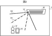
- FIG. 2 shows an indoor space 2 to which the air conditioning system 1 is applied as an example of the space to be air-conditioned.
- the indoor space 2 is, for example, one room in a detached house, an apartment house, an office building, a factory, a vehicle, or the like, and is an area in which the indoor unit 42 of the air conditioner 40 is installed.
- the indoor unit 42 is installed on the ceiling of the indoor space 2.
- the detection device 10 is installed in the vicinity of the air-conditioned air outlet in the indoor unit 42, and detects information about the user existing in the indoor space 2.
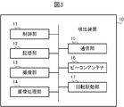
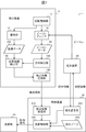
- the detection device 10 includes a control unit 11, a storage unit 12, an image pickup unit 13, an image processing unit 14, a communication unit 15, a beacon antenna 16, and a rotation drive unit 17. Be prepared. Each of these parts is connected via a communication bus.
- the control unit 11 includes a CPU (Central Processing Unit), a ROM (Read Only Memory), and a RAM (Random Access Memory).
- the CPU is also called a central processing unit, a central processing unit, a processor, a microprocessor, a microcomputer, a DSP (Digital Signal Processor), or the like, and is a central processing unit that executes processing and calculations related to the control of the detection device 10.
- the CPU reads out the programs and data stored in the ROM, and uses the RAM as a work area to control the detection device 10 in an integrated manner.
- the storage unit 12 is a non-volatile semiconductor memory such as a flash memory, EPROM (ErasableProgrammableROM), and EEPROM (ElectricallyErasableProgrammableROM), and plays a role as a so-called secondary storage device or auxiliary storage device.
- the storage unit 12 stores programs and data used by the control unit 11 to perform various processes.
- the control unit 11 stores data generated or acquired by performing various processes.
- the imaging unit 13 acquires an image of the inside of the indoor space 2 by imaging the indoor space 2 with infrared rays, visible light, or the like. Specifically, the imaging unit 13 images the imaging range R1 shown by the broken line in FIG. 2 in the indoor space 2.
- the imaging range R1 is a range determined by the viewing angle of the imaging unit 13. For example, as shown in FIG. 2, when the user in the indoor space 2 is located inside the imaging range R1, the imaging unit 13 acquires the captured image captured by the user.
- the imaging unit 13 will be described by taking as an example a case where the imaging unit 13 is a thermo camera that images the indoor space 2 with infrared rays and acquires a thermal image representing the temperature distribution in the imaging range R1 as the captured image.
- the imaging unit 13 functions as an imaging means.
- the image processing unit 14 includes a processor for image processing such as a DSP and a GPU (Graphics Processing Unit), and a buffer memory for temporarily storing the processed image.
- the image processing unit 14 executes a processing process for processing the captured image obtained by the imaging unit 13 and an image recognition process for recognizing a person, a person's face, an object, etc. included in the captured image.
- the communication unit 15 includes a communication interface for communicating with an external device including the terminal device 20 and the control device 30.
- the communication unit 15 communicates with an external device in accordance with well-known communication standards such as wireless LAN (Local Area Network), wired LAN, and USB (Universal Serial Bus).
- the beacon antenna 16 receives a beacon which is a signal transmitted from the terminal device 20 existing in the indoor space 2.
- the beacon is also called a radio beacon, and is a radio signal for transmitting information such as the position and ID of the source of the beacon to other devices.
- the beacon antenna 16 is an antenna that communicates with an external device by Bluetooth (registered trademark), and receives a beacon transmitted from the terminal device 20 in accordance with the BLE (Bluetooth Low Energy) standard.
- BLE Bluetooth Low Energy
- BLE Bluetooth Low Energy
- the beacon antenna 16 has directivity in a range in which the beacon can be received.
- the beacon antenna 16 can receive the beacon transmitted from the inside of the reception range R2 shown by the solid line in FIG.
- the beacon antenna 16 receives the beacon from the terminal device 20.
- the beacon antenna 16 does not receive the beacon transmitted from the terminal device 20.
- the rotation drive unit 17 includes drive members such as a motor and an actuator, and rotationally drives the image pickup unit 13 and the beacon antenna 16 to change their directions. As a result, the rotation drive unit 17 changes the image pickup range R1 by the image pickup unit 13 and the beacon reception range R2 by the beacon antenna 16. By the rotation drive by the rotation drive unit 17, the image pickup unit 13 can acquire the captured image over a wide range of the indoor space 2. Further, the beacon antenna 16 can receive a beacon transmitted from a wide range of the indoor space 2.
- the rotation drive unit 17 functions as a rotation drive means.
- the entire detection device 10 is mounted on the rotation drive unit 17 so that the entire detection device 10 can rotate and change its direction.
- the rotation drive unit 17 rotates the entire detection device 10 to rotate the image pickup unit 13 and the beacon antenna 16 mounted on the detection device 10 at the same time and at the same angular velocity.
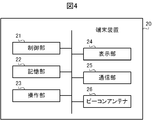
- the terminal device 20 is a smartphone, a tablet terminal, or the like, and is an operation terminal that is gripped and operated by a user existing in the indoor space 2. As shown in FIG. 4, the terminal device 20 includes a control unit 21, a storage unit 22, an operation unit 23, a display unit 24, a communication unit 25, and a beacon antenna 26. Each of these parts is connected via a communication bus.
- the control unit 21 includes a CPU, a ROM, and a RAM.
- the CPU is also called a central processing unit, a central processing unit, a processor, a microprocessor, a microcomputer, a DSP, or the like, and is a central processing unit that executes processing and calculations related to the control of the terminal device 20.
- the CPU reads out the programs and data stored in the ROM, and uses the RAM as a work area to control the terminal device 20 in an integrated manner.
- the storage unit 22 is a non-volatile semiconductor memory such as a flash memory, EPROM, or EEPROM, and plays a role as a so-called secondary storage device or auxiliary storage device.
- the storage unit 22 stores programs and data used by the control unit 21 to perform various processes.
- the control unit 21 stores data generated or acquired by performing various processes.
- the operation unit 23 is provided with input devices such as a keyboard, mouse, buttons, touch pad, and touch panel, and accepts operations from the user.
- the user can input various instructions to the terminal device 20 by operating the operation unit 23.
- the operation unit 23 receives the operation instruction input from the user, the operation unit 23 transmits the received operation instruction to the control unit 21.
- the operation unit 23 functions as an operation reception means.
- the display unit 24 includes a display device such as a liquid crystal display or an organic EL (Electro Luminescence) display.
- the display unit 24 is driven by a display drive circuit (not shown) and displays various images under the control of the control unit 21.
- the display unit 24 functions as a display means.
- the communication unit 25 includes a communication interface for communicating with an external device including the detection device 10 and the control device 30.
- the communication unit 25 communicates with an external device according to a well-known communication standard such as a wireless LAN.
- the beacon antenna 26 transmits a beacon around the terminal device 20.
- the beacon antenna 26 is an antenna that communicates with an external device by Bluetooth (registered trademark), and repeatedly transmits a beacon having a predetermined intensity in a predetermined cycle in accordance with the BLE standard.
- the beacon antenna 26 is an antenna having no directivity, and transmits a beacon in all directions around it.
- the beacon antenna 16 of the detection device 10 is a directional antenna
- the beacon antenna 26 of the terminal device 20 is an omnidirectional antenna.
- the terminal device 20 is located within a range that can be communicated with the detection device 10 by Bluetooth (registered trademark)
- the beacon transmitted from the beacon antenna 26 is received by the beacon antenna 16 of the detection device 10.
- the beacon transmitted from the beacon antenna 26 includes identification information for identifying the terminal device 20.
- the identification information is also called a beacon ID, and is information uniquely set for each terminal device 20 which is the source of the beacon so that the source of the beacon can be identified from the side receiving the beacon.
- the control device 30 is a device that controls the air conditioning of the indoor space 2 by the air conditioner 40.
- the control device 30 is, for example, a remote controller that is operated by a user existing in the indoor space 2 and transmits various commands to the air conditioner 40.
- the control device 30 may be built in, for example, the indoor unit 42 of the air conditioner 40.
- the control device 30 controls the air conditioner 40 by transmitting and receiving various signals to and from the air conditioner 40.
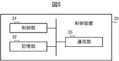
- the control device 30 includes a control unit 31, a storage unit 32, and a communication unit 35. Each of these parts is connected via a communication bus.
- the control unit 31 includes a CPU, ROM, and RAM.
- the CPU is also called a central processing unit, a central processing unit, a processor, a microprocessor, a microcomputer, a DSP, or the like, and is a central processing unit that executes processing and calculations related to the control of the control device 30.
- the CPU reads out the programs and data stored in the ROM, and uses the RAM as a work area to control the control device 30 in an integrated manner.
- the storage unit 32 is a non-volatile semiconductor memory such as a flash memory, EPROM, or EEPROM, and plays a role as a so-called secondary storage device or auxiliary storage device.
- the storage unit 32 stores programs and data used by the control unit 31 to perform various processes.
- the control unit 31 stores data generated or acquired by performing various processes.
- the communication unit 35 includes a communication interface for communicating with an external device including the detection device 10, the terminal device 20, and the air conditioner 40.
- the communication unit 35 communicates with an external device according to a well-known communication standard such as a wireless LAN.
- the air conditioner 40 is a heat pump type air conditioner that uses CO 2 (carbon dioxide), HFC (hydrofluorocarbon), or the like as a refrigerant.
- the air conditioner 40 air-conditions the indoor space 2 which is the space to be air-conditioned.
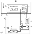
- FIG. 6 shows the configuration of the air conditioner 40.
- the air conditioner 40 includes an outdoor unit 41 installed outside the indoor space 2 and an indoor unit 42 installed in the indoor space 2.
- the outdoor unit 41 and the indoor unit 42 are connected via a refrigerant circuit 50 through which the refrigerant flows and a communication line 43.
- the outdoor unit 41 includes a compressor 51, a four-way valve 52, an outdoor heat exchanger 53, an expansion valve 54, an outdoor fan 56, and an outdoor unit control unit 44.
- the indoor unit 42 includes an indoor heat exchanger 55, an indoor fan 57, and an indoor unit control unit 45.
- the refrigerant circuit 50 circularly connects the compressor 51, the four-way valve 52, the outdoor heat exchanger 53, the expansion valve 54, and the indoor heat exchanger 55. This constitutes a refrigeration cycle.
- the compressor 51 compresses the refrigerant and circulates the refrigeration cycle. Specifically, the compressor 51 compresses the low-temperature and low-pressure refrigerant, and discharges the high-pressure and high-temperature refrigerant to the four-way valve 52.
- the compressor 51 includes an inverter circuit capable of changing the operating capacity according to the drive frequency.
- the operating capacity is the amount that the compressor 51 sends out the refrigerant per unit time.
- the compressor 51 changes the operating capacity by adjusting the drive frequency according to the instruction from the outdoor unit control unit 44.
- the four-way valve 52 is installed on the discharge side of the compressor 51.
- the four-way valve 52 switches the flow direction of the refrigerant in the refrigerant circuit 50 depending on whether the operation of the air conditioner 40 is a cooling or dehumidifying operation or a heating operation.
- the outdoor heat exchanger 53 is a first heat exchanger that exchanges heat between the refrigerant flowing through the refrigerant circuit 50 and the outside air in the indoor space 2.
- the outdoor fan 56 is provided near the outdoor heat exchanger 53, and is a first blower that sends the outside air of the indoor space 2 to the outdoor heat exchanger 53.
- a negative pressure is generated inside the outdoor unit 41 and sucks in the air outside the indoor space 2.
- the sucked air is supplied to the outdoor heat exchanger 53, exchanges heat with the cold / hot heat supplied by the refrigerant flowing through the refrigerant circuit 50, and then is blown out to the outside of the indoor space 2.
- the expansion valve 54 is installed between the outdoor heat exchanger 53 and the indoor heat exchanger 55, and decompresses and expands the refrigerant flowing through the refrigerant circuit 50.
- the expansion valve 54 is an electronic expansion valve whose opening degree can be variably controlled.
- the expansion valve 54 adjusts the pressure of the refrigerant by changing the opening degree according to the instruction from the outdoor unit control unit 44.
- the indoor heat exchanger 55 is a second heat exchanger that exchanges heat between the refrigerant flowing through the refrigerant circuit 50 and the air in the indoor space 2.
- the indoor fan 57 is provided near the indoor heat exchanger 55, and is a second blower that sends the air in the indoor space 2 to the indoor heat exchanger 55.
- a negative pressure is generated inside the indoor unit 42 and sucks the air in the indoor space 2.
- the sucked air is supplied to the indoor heat exchanger 55, and after heat exchange with the cold / hot heat supplied from the refrigerant flowing through the refrigerant circuit 50, the air is blown out into the indoor space 2.
- the air heat-exchanged by the indoor heat exchanger 55 is blown out from the outlet as air-conditioned air and supplied to the indoor space 2.
- the indoor space 2 is air-conditioned.
- the outdoor unit control unit 44 and the indoor unit control unit 45 include a CPU, ROM, RAM, a communication interface, and a readable / writable non-volatile semiconductor memory, and control the operations of the outdoor unit 41 and the indoor unit 42, respectively. ..
- the outdoor unit control unit 44 and the indoor unit control unit 45 are connected by a communication line 43, and cooperate with each other by exchanging various signals via the communication line 43 to control the entire air conditioner 40.
- the detection device 10 functionally includes a rotation control unit 110, a direction detection unit 120, a position information detection unit 130, and a detection information transmission unit 140.
- a rotation control unit 110 functionally includes a rotation control unit 110, a direction detection unit 120, a position information detection unit 130, and a detection information transmission unit 140.
- Each of these functions is realized by software, firmware, or a combination of software and firmware.
- the software and firmware are described as a program and stored in the ROM or the storage unit 12. Then, the CPU realizes each of these functions by executing the program stored in the ROM or the storage unit 12.
- the rotation control unit 110 rotates the image pickup unit 13 and the beacon antenna 16 to change their directions by controlling the rotation drive by the rotation drive unit 17. Specifically, the rotation control unit 110 drives the rotation drive unit 17 while the detection device 10 is executing the detection operation, and simultaneously rotates the image pickup unit 13 and the beacon antenna 16 at a predetermined angular velocity. Let me.
- the rotation control unit 110 is realized by the control unit 11 cooperating with the rotation drive unit 17.
- the rotation control unit 110 functions as a rotation control means.
- the rotation control unit 110 sets the image pickup unit 13 and the beacon antenna 16 in the origin direction so that the user can be imaged and the beacon can be received regardless of the position of the user in the indoor space 2. It is repeatedly reciprocated between the + 180 ° direction and the -180 ° direction as the center. As a result, the rotation control unit 110 scans the imaging unit 13 and the beacon antenna 16 evenly over 360 ° around the detection device 10.
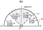
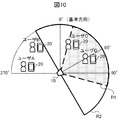
- FIGS. 8 to 10 show an example in which the imaging unit 13 and the beacon antenna 16 are rotated when a plurality of users A to D exist in the indoor space 2.
- the imaging range R1 by the imaging unit 13 is represented by a broken line
- the beacon receiving range R2 by the beacon antenna 16 is represented by a solid line.
- the image pickup unit 13 and the beacon antenna 16 are installed in the vicinity, and are rotationally driven by one rotation drive unit 17 at the same time. Therefore, the imaging range R1 by the imaging unit 13 and the beacon receiving range R2 by the beacon antenna 16 are ranges having substantially the same position as the apex. 8 to 10 show, as an example, a case where the viewing angle of the imaging unit 13 is 90 ° and the beacon antenna 16 has directivity about the front and back of the detection device 10.
- the reception range R2 includes all users A to D. Therefore, the beacon antenna 16 receives the beacon transmitted from the terminal devices 20 of the users A to D.
- the imaging range R1 includes users B and C, but does not include users A and D. Therefore, the image pickup unit 13 acquires a captured image in which users B and C are included and users A and D are not included.
- the imaging unit 13 and the beacon antenna 16 are rotated by 30 ° from the state of FIG. 8, the user A is out of the reception range R2 as shown in FIG. On the other hand, the user B is excluded from the imaging range R1, and the user D is newly included in the imaging range R1. Further, when the imaging unit 13 and the beacon antenna 16 are rotated by 60 ° from the state of FIG. 8, the user B is out of the reception range R2 as shown in FIG. On the other hand, the imaging range R1 is maintained while including the users C and D.
- the rotation control unit 110 gradually changes the image pickup range R1 and the beacon reception range R2 by rotating the image pickup unit 13 and the beacon antenna 16. As a result, it is possible to acquire captured images of users A to D existing at various positions in the indoor space 2, and to receive beacons transmitted from the terminal device 20 held by users A to D. ..
- the direction detection unit 120 determines the beacon antenna 16 based on the change in the intensity of the beacon received by the beacon antenna 16 while the imaging unit 13 and the beacon antenna 16 are rotating by the rotation drive unit 17. Detects the direction from to the terminal device 20.
- the direction detection unit 120 obtains beacon data regarding the beacon received by the beacon antenna 16 while the beacon antenna 16 is being rotated by the rotation control unit 110 in order to detect the direction from the beacon antenna 16 to the terminal device 20. It is stored in the storage unit 12 as 180.
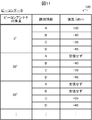
- FIG. 11 shows an example of beacon data 180.
- the beacon data 180 is a data table in which the angle of the beacon antenna 16, the identification information of the terminal device 20 included in the received beacon, and the intensity of the received beacon are associated with each other.
- the direction detection unit 120 updates the beacon data 180 stored in the storage unit 12 every time the beacon antenna 16 is rotated by a rotation control unit 110 at a predetermined angle.
- the direction detection unit 120 receives data from the terminal devices 20 of users A to D in association with an angle of 0 °.
- the intensity of the beacon and the identification information of the terminal devices 20 of the users A to D are stored in the beacon data 180.
- the direction detection unit 120 associates the beacon data with the intensity of the beacon received from the terminal devices 20 of the users B to D and the identification information of the terminal devices 20 of the users B to D in association with the angle of 30 °. Store at 180. On the other hand, the direction detection unit 120 stores the intensity of the beacon received from the terminal device 20 of the user A as "not received".
- the direction detection unit 120 associates the beacon data with the intensity of the beacon received from the terminal devices 20 of the users C and D and the identification information of the terminal devices 20 of the users C and D in association with the angle of 60 °. Store at 180. On the other hand, the direction detection unit 120 stores the intensity of the beacon received from the terminal devices 20 of the users A and B as "not received".
- the direction detection unit 120 detects the direction from the beacon antenna 16 to the terminal device 20 with reference to such beacon data 180. More specifically, the direction detection unit 120 determines whether or not the intensity of the beacon received from any of the terminal devices 20 is significantly lower than a predetermined threshold value. As a result of the determination, when the intensity of the beacon received from any of the terminal devices 20 is significantly lower than the threshold value, the direction detection unit 120 receives the angle and reception of the beacon antenna 16 when the intensity of the beacon is significantly lower than the threshold value.
- the direction defined by the range R2 is detected as the direction from the beacon antenna 16 to the terminal device 20.
- the threshold value is set in advance to a value that can determine whether the beacon is received from the terminal device 20 located inside the reception range R2 and the beacon is not received.
- the direction detection unit 120 is an angle from 0 to 30 °, which is the angle of the beacon antenna 16 when the intensity of the beacon drops significantly below the threshold value, from the center direction to the end of the beacon reception range R2. Calculate the direction of the angle minus 90 °.
- the direction detection unit 120 detects a direction in the range of 270 to 300 °, which is a direction of ⁇ 90 ° with respect to 0 to 30 °, as a direction from the beacon antenna 16 to the terminal device 20 of the user A. To do.
- the direction detection unit 120 detects a direction in the range of 300 to 330 °, which is a direction of ⁇ 90 ° with respect to 30 to 60 °, as a direction from the beacon antenna 16 to the terminal device 20 of the user B.
- the direction detection unit 120 transfers the direction deviating from the inside to the outside of the reception range R2 from the beacon antenna 16 to the terminal device 20 when the intensity of the beacon received from the terminal device 20 drops significantly below the threshold value. Detect as direction.
- the direction detection unit 120 is realized by the control unit 11 cooperating with the beacon antenna 16.
- the direction detection unit 120 functions as a direction detection means.
- the position information detecting unit 130 enters the indoor space 2 based on the captured image obtained by the imaging unit 13 capturing the region in the direction detected by the direction detecting unit 120 in the indoor space 2. Detects the location information of existing users.
- the position information detection unit 130 is realized by the control unit 11 cooperating with the image processing unit 14.
- the position information detection unit 130 functions as a position information detection means.
- the position information detection unit 130 captures a plurality of captured images obtained by the imaging unit 13 capturing various directions in the indoor space 2 while the imaging unit 13 is rotating by the rotation control unit 110. Is stored in the storage unit 12.
- FIG. 12 shows an example of the imaging data 190.
- the imaging data 190 is a data table in which the angle of the imaging unit 13 and the data of the captured image are linked.
- the position information detection unit 130 updates the image pickup data 190 stored in the storage unit 12 every time the image pickup unit 13 rotates at a predetermined angle by the rotation control unit 110.
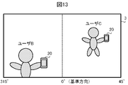
- FIG. 13 shows an example of the captured image 3 captured by the imaging unit 13.
- the captured image 3 shown in FIG. 13 is when the angle of the imaging unit 13 is 0 °, that is, when the optical axis of the imaging unit 13 is oriented at 0 °, which is the reference direction, as shown in FIG.
- This is an image captured by users B and C located inside the imaging range R1 having a viewing angle of ⁇ 45 °.
- the captured image 3 is a thermal image captured by infrared rays, it represents the temperature distribution of the users B and C who are holding the terminal device 20 in the indoor space 2.
- the imaging data 190 stores such an captured image 3 as a predetermined angle every 30 °.
- the position information detection unit 130 detects a user from the captured images by analyzing the captured images stored in such captured data 190.
- the position information detection unit 130 uses a well-known image recognition technique in order to detect a user from the captured image. For example, the position information detection unit 130 recognizes a person's face, body, etc. in the captured image, or recognizes a moving heat source in the captured image, so that any part of the captured image of the person Determine if the image is included.
- the position information detection unit 130 detects a region in the captured image in which the at least one user is captured. For example, when the captured image 3 shown in FIG. 13 is analyzed, the position information detection unit 130 detects the regions of the users B and C in the captured image 3.
- the position information detection unit 130 detects a region in the direction detected by the direction detection unit 120 among a plurality of captured images obtained by the image pickup unit 13 capturing images in various directions stored in the image pickup data 190. Based on the captured image obtained by the imaging unit 13, the position information of the user existing in the indoor space 2 is detected.
- the captured image obtained by the imaging unit 13 taking an image of the region in the direction detected by the direction detecting unit 120 is such that the direction detected by the direction detecting unit 120 enters the field of view of the imaging unit 13. It means the captured image obtained in the state of being.
- the captured image corresponds to a captured image obtained when the rotating imaging unit 13 is facing the direction detected by the direction detecting unit 120.
- the position information detection unit 130 uses the image pickup unit 130.
- the position information of the user A is detected based on the captured image obtained when 13 is facing the direction of 270 to 300 °.
- the position information detection unit 130 faces the image pickup unit 13 in the direction of 300 to 330 °.
- the position information of the user B is detected based on the captured image obtained during the operation.
- the position information detection unit 130 detects the distance from the indoor unit 42 to the user as position information based on the size of the user in the captured image.
- the position information detection unit 130 uses the result of the user detection process executed on the captured image of the direction detected by the direction detection unit 120. Specifically, the position information detection unit 130 calculates the area or width of a region such as the user's face or body in the captured image detected by the user detection process as the size of the user in the captured image. Then, the position information detection unit 130 determines that the distance from the indoor unit 42 to the user is closer when the size of the user in the captured image is larger, and when the size of the user in the captured image is smaller, It is determined that the distance from the indoor unit 42 to the user is longer.
- the detection information transmission unit 140 transmits the detection information detected by the detection device 10 to the control device 30.
- the detection information is information including the user's position information detected by the position information detection unit 130, the direction detected by the direction detection unit 120, and the identification information of the terminal device 20 held by the user. ..
- the detection information transmission unit 140 When the position information of the user is detected by the position information detection unit 130, the detection information transmission unit 140 includes the detected user's position information, the identification information included in the beacon received from the user's terminal device 20, and the identification information. The detection information is generated by associating the direction from the beacon antenna 16 detected by the direction detection unit 120 with the direction to the terminal device 20. Then, the detection information transmission unit 140 communicates with the control device 30 via the communication unit 15 and transmits the generated detection information to the control device 30.
- the detection information transmission unit 140 is realized by the control unit 11 cooperating with the communication unit 15.
- the detection information transmission unit 140 functions as a detection information transmission means.
- the control device 30 functionally includes a detection information receiving unit 310, a terminal communication unit 320, and an air conditioning control unit 330.
- Each of these functions is realized by software, firmware, or a combination of software and firmware.
- the software and firmware are described as a program and stored in the ROM or the storage unit 32. Then, the CPU realizes each of these functions by executing the program stored in the ROM or the storage unit 32.
- the detection information receiving unit 310 receives the detection information transmitted from the detection device 10.
- the detection information transmitting unit 140 transmits the detection information indicating the user's position information and the identification information detected by the detection device 10
- the detection information receiving unit 310 communicates with the detection device 10 via the communication unit 35. Receives the transmitted detection information.
- the detection information receiving unit 310 is realized by the control unit 31 cooperating with the communication unit 35.
- the detection information receiving unit 310 functions as a detection information receiving unit.
- the terminal communication unit 320 communicates with the terminal device 20 via the communication unit 35. Specifically, the terminal communication unit 320 receives from the terminal device 20 operation information indicating the air conditioning operation received from the user in the terminal device 20. In the terminal device 20, when the control unit 21 receives, for example, an operation for switching the operation mode of air conditioning by the air conditioner 40, or an input operation such as a set temperature, a set humidity, and a ventilation mode from the user by the operation unit 23, the accepted operation. The operation information indicating the above is transmitted to the control device 30 by the communication unit 25. The terminal communication unit 320 receives the operation information transmitted from the terminal device 20 in this way.
- the terminal communication unit 320 transmits the state information indicating the air conditioning state of the indoor space 2 to the terminal device 20.
- the state information is information indicating, for example, the operation mode, set temperature, set humidity, and ventilation mode of the current air conditioning by the air conditioner 40.
- the terminal communication unit 320 spontaneously transmits such state information to the terminal device 20 at a predetermined timing or in response to a request from the terminal device 20.
- the control unit 21 receives the state information transmitted by the terminal communication unit 320, the control unit 21 notifies the user by displaying the received state information on the display unit 24.
- the terminal communication unit 320 is realized by the control unit 31 cooperating with the communication unit 35.
- the terminal communication unit 320 functions as a terminal communication means.
- the air conditioning control unit 330 controls the air conditioning of the indoor space 2 by the air conditioner 40 by transmitting a control command to the air conditioner 40 via the communication unit 35.
- the air conditioning control unit 330 is realized by the control unit 31 cooperating with the communication unit 35.
- the air conditioning control unit 330 functions as an air conditioning control means.
- the air conditioning control unit 330 controls the air conditioning by the air conditioner 40 according to the received operation information. For example, when the operation information for switching the operation mode is received from the terminal device 20, the air conditioning control unit 330 switches the operation mode according to the received operation information. Further, when receiving the operation information for changing the set temperature, the set humidity or the ventilation mode from the terminal device 20, the air conditioning control unit 330 changes the set temperature, the set humidity or the ventilation mode according to the received operation information.
- the air conditioning control unit 330 controls the air conditioning of the indoor space 2 by the air conditioner 40 based on the detection information received from the detection device 10 by the detection information receiving unit 310.
- the detection information is the position information of the user existing in the indoor space 2 detected by the position information detection unit 130, the identification information of the terminal device 20 held by the user, and the direction detection unit 120. Information on the direction from the detected beacon antenna 16 to the terminal device 20 is included. Therefore, the air conditioning control unit 330 controls the air conditioning by the air conditioner 40 based on the user's position information, the identification information of the terminal device 20, and the direction from the beacon antenna 16 to the terminal device 20.
- the air conditioning control unit 330 controls the air conditioning by the air conditioner 40 based on the position information included in the detection information received by the detection information receiving unit 310. More specifically, the air conditioning control unit 330 refers to the distance from the indoor unit 42 to the user, which is detected as position information by the position information detection unit 130. Then, the air conditioning control unit 330 controls the air conditioning so as to enhance the comfort of the user who exists at the position of the detected distance.
- the air conditioning control unit 330 adjusts the strength of blowing out the air conditioning air or the vertical angle so that the air conditioning air blown out from the indoor unit 42 reaches farther. To do.
- the air conditioning control unit 330 blows out the conditioned air so that the conditioned air blown from the indoor unit 42 is concentrated in a closer range, or the vertical angle. To adjust.
- the air conditioning control unit 330 controls the air conditioning by the air conditioner 40 based on the direction detected by the direction detection unit 120. Specifically, the air conditioning control unit 330 directs the direction of the air conditioning air blown out from the indoor unit 42 to the direction detected by the direction detecting unit 120 so that the air conditioning air is blown out toward the user. Alternatively, on the contrary, the air conditioning control unit 330 detects the direction of the air conditioning air blown out from the indoor unit 42 by the direction detection unit 120 so that the air conditioning air does not directly hit the user. It may be directed in a direction other than the direction.
- the air conditioning control unit 330 controls the air conditioning by the air conditioner 40 based on the identification information included in the detection information received by the detection information receiving unit 310 in addition to the user's position information. Specifically, the air conditioning control unit 330 controls the air conditioning of the indoor space 2 with the control content corresponding to the identification information included in the beacon received by the beacon antenna 16 from the direction detected by the direction detection unit 120. .. Therefore, the air conditioning control unit 330 refers to the preference data 340 stored in the storage unit 32.
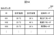
- FIG. 14 shows an example of preference data 340.
- the preference data 340 is a data table that stores information indicating the user's air conditioning preference in association with each terminal device 20 operated by the user. Specifically, as shown in FIG. 14, the preference data 340 stores information on the set temperature, the set humidity, and the ventilation mode as information indicating the user's air conditioning preference in association with the identification information of the terminal device 20. doing.
- the preference data 340 is generated from each of the plurality of terminal devices 20 existing in the indoor space 2 based on the history of operation information received in the past by the terminal communication unit 320, and is stored in the storage unit 32.
- the air-conditioning control unit 330 sets representative values such as the average value and the mode of the set temperature set in the terminal device 20 in the past for each user as the preferred set temperature of each user, and sets the terminal device 20 of each user. It is saved in association with the identification information of. The same applies to the set humidity. Further, the air-conditioning control unit 330 stores the ventilation mode set most in the past in the terminal device 20 for each user as the favorite ventilation mode of each user in association with the identification information of the terminal device 20 of each user. ..
- the air conditioning control unit 330 is associated with the identification information of the terminal device 20 in the preference data 340. Update the stored set temperature, set humidity or ventilation mode.
- the air conditioning control unit 330 determines the control content of the air conditioner with reference to such preference data 340, and causes the air conditioner 40 to air-condition with the determined control content. Specifically, the air conditioning control unit 330 causes the air conditioner 40 to air-condition at a set temperature, a set humidity, or a ventilation mode associated with the identification information included in the detection information received by the detection information receiving unit 310. In this way, the air conditioning control unit 330 causes the air conditioner 40 to perform air conditioning according to the user's preference by changing the air conditioning control content according to the identification information of the terminal device 20. Thereby, the comfort of the user can be improved.
- the air conditioning control unit 330 is among the plurality of users.
- the air conditioning is controlled based on the identification information of the terminal device 20 of the user having the highest priority. For example, the user who spends the longest time in the indoor space 2, that is, the user who has the longest elapsed time since the position information was detected by the detection device 10, is set to have the highest priority. Alternatively, the priority of the user who exists at the position closest to the indoor unit 42 may be set to the highest priority.
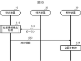
- the flow of processing executed in the air conditioning system 1 configured as described above will be described with reference to the sequence diagram shown in FIG.
- the process shown in FIG. 15 is appropriately executed in a state in which each of the detection device 10, the terminal device 20, and the control device 30 can normally execute the process.
- the control unit 21 emits a beacon from the beacon antenna 26 at a predetermined cycle (step S11).
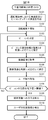
- the control unit 11 executes the position information detection process based on the beacon transmitted from the terminal device 20 (step S12). The details of the position information detection process in step S12 will be described with reference to the flowchart shown in FIG.
- the control unit 11 When the position information detection process shown in FIG. 16 is started, the control unit 11 first acquires the angles of the imaging unit 13 and the beacon antenna 16 at the start of operation (step S101). Specifically, the control unit 11 acquires the angles of the image pickup unit 13 and the beacon antenna 16 with respect to a predetermined reference direction at the start of operation. As a result, the control unit 11 acquires information on which direction the image pickup unit 13 and the beacon antenna 16 are facing in the initial state.
- control unit 11 may return the directions of the image pickup unit 13 and the beacon antenna 16 to the reference direction at the start of operation or the end of operation by the function of the rotation control unit 110. In that case, the angle between the imaging unit 13 and the beacon antenna 16 at the start of operation is 0 °.
- control unit 11 functions as the rotation control unit 110, and starts the rotation drive of the image pickup unit 13 and the beacon antenna 16 (step S102). Specifically, the control unit 11 drives the rotation drive unit 17 to rotate the image pickup unit 13 and the beacon antenna 16 at a predetermined angular velocity. As a result, the control unit 11 gradually changes the range R1 imaged by the image pickup unit 13 and the range R2 in which the beacon can be received by the beacon antenna 16.
- the control unit 11 receives the beacon transmitted from the terminal device 20 existing in the indoor space 2 by the beacon antenna 16 which is rotationally driven (step S103). For example, as shown in FIGS. 8 to 10, when at least one user holding the terminal device 20 is located inside the beacon reception range R2, the control unit 11 controls the beacon reception range R2. Receives a beacon transmitted from the user's terminal device 20 located inside. On the other hand, if no user holding the terminal device 20 is located inside the beacon reception range R2, the control unit 11 does not receive the beacon.
- the control unit 11 Upon receiving the beacon, the control unit 11 saves the identification information and the intensity of the received beacon in association with the angle of the beacon antenna 16 (step S104). Specifically, each time the beacon antenna 16 rotates at a predetermined angle, the control unit 11 associates the newly received beacon identification information and the intensity with the angle at that time, and the beacon data 180. Add to.
- the control unit 11 acquires the captured image by using the image pickup unit 13 which is rotationally driven (step S105). For example, as shown in FIGS. 8 to 10, when at least one user is located inside the imaging range R1, the control unit 11 includes an captured image including the user located inside the imaging range R1. To get. On the other hand, when no user is located inside the imaging range R1, the control unit 11 acquires an captured image that does not include the user.
- the control unit 11 saves the acquired image data in association with the angle of the imaging unit 13 (step S106). Specifically, each time the imaging unit 13 rotates a predetermined angle, the control unit 11 associates the newly acquired captured image data with the angle at that time and adds it to the imaging data 190.
- control unit 11 executes the user detection process on the saved captured image (step S107). Specifically, the control unit 11 determines whether or not the user is included in any part of the captured image. When the captured image includes at least one user, the control unit 11 identifies the position and size of the at least one user in the captured image.
- the control unit 11 determines whether or not the amount of decrease in the intensity of the beacon received from any of the terminal devices 20 existing in the indoor space 2 exceeds the threshold value (step S108). Specifically, the control unit 11 refers to the beacon data 180 stored in the storage unit 12, and stores the beacon intensity at the angle newly stored in the beacon data 180 and the beacon data immediately before the beacon data 180. The intensity of the beacon at the angle is compared for each terminal device 20. Then, in any of the terminal devices 20, the control unit 11 causes the intensity of the beacon at the newly stored angle to be significantly lower than the threshold value as compared with the intensity of the beacon at the angle stored immediately before that. Judge whether or not it is.
- step S108 When the amount of decrease in the intensity of the beacon received from any of the terminal devices 20 does not exceed the threshold value (step S108; NO), the control unit 11 returns the process to step S103 and executes the processes of steps S103 to S108 again. .. Specifically, the control unit 11 continuously drives the image pickup unit 13 and the beacon antenna 16 to rotate, and the image pickup unit 13 captures the indoor space 2 to update the capture data 190. The process of detecting and the process of receiving the beacon by the beacon antenna 16 and updating the beacon data 180 are executed.
- the control unit 11 functions as the direction detection unit 120 and determines the intensity of the beacon. Based on the change, the direction to the terminal device 20 is detected (step S109). Specifically, the control unit 11 is an angle from the center direction to the end of the beacon reception range R2 with respect to the angle of the beacon antenna 16 at the timing when the amount of decrease in the beacon intensity exceeds the threshold value 90. The direction obtained by subtracting ° is specified as the direction from the beacon antenna 16 to the terminal device 20.
- the control unit 11 When the direction to the terminal device 20 is specified, the control unit 11 functions as the position information detection unit 130 and detects the user's position information (step S110). Specifically, the control unit 11 is indoors based on the size of the user in the captured image obtained when the rotationally driven imaging unit 13 is facing the direction detected in step S109. The distance from the machine 42 to the user is detected. As a result, the position information detection process shown in FIG. 16 is completed.
- the control unit 11 functions as the detection information transmission unit 140 and corresponds to the user's position information detected in step S12.
- the identification information of the terminal device 20 and the detection information including the terminal device 20 are transmitted to the control device 30 (step S13).
- the control unit 31 functions as the detection information receiving unit 310 in step S13, and receives the detection information transmitted from the detection device 10.
- control unit 31 When the control device 30 receives the detection information, the control unit 31 functions as the air conditioning control unit 330, and the air conditioner 40 air-conditions the indoor space 2 based on the position information and the identification information included in the received detection information. Is controlled (step S14).
- the air conditioning system 1 realizes air conditioning according to the user's position and preference by repeatedly executing the processes of steps S11 to S14 as described above.
- the control unit 21 when the control unit 21 receives an air conditioning operation from the user, the control unit 21 transmits the operation information to the control device 30, and the control device 30 is air-conditioned according to the received operation. Let it be controlled. Further, in the control device 30, the control unit 31 transmits the state information indicating the air conditioning state to the terminal device 20 and causes the terminal device 20 to display the state information.
- the beacon antenna 16 is based on the change in the intensity of the beacon received by the beacon antenna 16 when the beacon antenna 16 having directivity is rotating. Based on the captured image obtained by detecting the direction from the antenna to the terminal device 20 and imaging the region in the detected direction in the indoor space 2, the position information of the user existing in the indoor space 2 is obtained. To detect. As described above, the air conditioning system 1 according to the first embodiment detects the direction to the terminal device 20 by using the beacon, and then the user of the terminal device 20 whose direction is detected by using the image pickup by the imaging unit 13. Detect location information. Therefore, the position information of the user in the indoor space 2 can be detected more accurately than when only the beacon is used or when only the imaging is used. As a result, the air conditioning can be controlled according to the user's position information, which leads to improvement of comfort and energy saving.
- the air conditioning system 1 controls the air conditioning of the indoor space 2 based on the identification information of the terminal device 20 included in the beacon received by the beacon antenna 16. As a result, even when the indoor space 2 is used by a plurality of users, the air conditioning control can be performed according to the preference of each user, so that the comfort can be further improved.
- Embodiment 2 of the present invention will be described. The same matters as in the first embodiment will be omitted as appropriate.
- the rotation control unit 110 rotates the image pickup unit 13 and the beacon antenna 16 regardless of whether or not an operation is accepted from the user in the terminal device 20.
- the rotation control unit 110 starts the rotation of the image pickup unit 13 and the beacon antenna 16 in response to the operation received from the user in the terminal device 20.
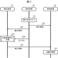
- the control unit 21 of the terminal device 20 receives an air conditioning operation from the user via the operation unit 23 (step S21).
- the control unit 21 receives from the user an operation of switching the operation mode of air conditioning by the air conditioner 40, or an operation of setting a set temperature, a set humidity, a ventilation mode, and the like.
- the operation unit 23 functions as an operation receiving means.
- control unit 21 transmits the operation information indicating the accepted operation to the control device 30 (step S22).
- control unit 31 functions as a terminal communication unit 320 and receives the transmitted operation information.
- control unit 21 transmits the identification information of the terminal device 20 to the detection device 10 in response to the reception of the air conditioning operation (step S23).
- control unit 11 receives the identification information transmitted from the terminal device 20.
- the control unit 21 transmits the identification information to the detection device 10 by communicating with the detection device 10 via the communication unit 25.
- the control unit 21 may transmit the identification information together with the operation information to the control device 30, and transmit the identification information to the detection device 10 via the control device 30.
- the control unit 21 notifies the detection device 10 that the terminal device 20 has received the air conditioning operation from the user.
- the control unit 21 transmits a beacon from the beacon antenna 26 at a predetermined cycle. (Step S24). Then, in the detection device 10, the control unit 11 executes the position information detection process based on the beacon transmitted from the terminal device 20 (step S25).
- step S25 is basically the same as the position information detection process in the first embodiment shown in FIG. However, in step S102, when the operation unit 23 of the terminal device 20 receives the air conditioning operation from the user, the rotation control unit 110 starts the rotation of the image pickup unit 13 and the beacon antenna 16.
- the rotation control unit 110 rotationally drives the image pickup unit 13 and the beacon antenna 16 regardless of whether or not the operation is accepted by the terminal device 20.
- the rotation control unit 110 does not rotate the image pickup unit 13 and the beacon antenna 16 until the terminal device 20 accepts the air conditioning operation, and the terminal device 20 performs the air conditioning operation. After being accepted, the imaging unit 13 and the beacon antenna 16 start to rotate.
- the rotation control unit 110 determines whether or not the air conditioning operation has been accepted by the terminal device 20 based on whether or not the identification information has been received from the terminal device 20.
- the rotation control unit 110 starts the rotation of the image pickup unit 13 and the beacon antenna 16 in response to receiving the identification information from the terminal device 20 in step S23.
- the rotation control unit 110 detects the direction of the terminal device 20 that has received the operation, that is, the terminal device 20 that is the source of the identification information, among the plurality of terminal devices 20 existing in the indoor space 2.
- the process of detecting the position information of the user who operates the terminal device 20 is started.
- the rotation control unit 110 stops the rotation of the image pickup unit 13 and the beacon antenna 16 when the direction detection unit 120 detects the direction to the terminal device 20 which is the transmission source of the identification information in step S109. More specifically, in the first embodiment, the rotation control unit 110 includes the image pickup unit 13 and the beacon even after the direction detection unit 120 detects the direction to any of the terminal devices 20 existing in the indoor space 2. The antenna 16 continued to rotate. On the other hand, in the second embodiment, the rotation control unit 110 stops the rotation of the image pickup unit 13 and the beacon antenna 16 at the timing when the direction to the target terminal device 20 is detected.
- the rotation control unit 110 detects the direction from the beacon antenna 16 to the terminal device 20 by the direction detection unit 120 in step S109, the identification information included in the beacon received from the terminal device 20 is stepped. It is determined whether or not the identification information received in S23 matches. If the identification information matches as a result of the determination, the rotation control unit 110 identifies the terminal device 20 whose direction has been detected as the target terminal device 20, that is, the terminal device 20 whose operation has been accepted by the user. .. Then, the rotation control unit 110 stops the rotation of the imaging unit 13 and the beacon antenna 16. Since the processes other than steps S102 and S109 are the same as the position information detection process in the first embodiment shown in FIG. 16, the description thereof will be omitted.
- the control unit 11 transmits the detection information including the user's position information and the identification information of the corresponding terminal device 20 to the control device 30 (step). S26).
- the control unit 31 receives the detection information transmitted from the detection device 10 and controls the air conditioning based on the received detection information (step S27). Since the processes of steps S26 and S27 are the same as those of steps S13 and S14 in the first embodiment, the description thereof will be omitted.
- the image pickup unit 13 and the beacon antenna 16 are not rotated until the terminal device 20 accepts the air conditioning operation, and the terminal device 20 performs the air conditioning operation.
- the rotation of the imaging unit 13 and the beacon antenna 16 is started.
- the imaging unit 13 and the beacon are directly connected from the direction of the initial state to the direction of the user who input the operation to the terminal device 20.
- the direction of the antenna 16 can be changed. Therefore, the position information of the user who has input the operation to the terminal device 20 can be detected in a short time and reflected in the air conditioning control.
- the rotation of the imaging unit 13 and the beacon antenna 16 is started after the operation is received by the terminal device 20, and the direction from the beacon antenna 16 to the terminal device 20 is further detected. Since the rotation is stopped at the timing, unnecessary power consumption can be suppressed.
- Embodiment 3 of the present invention will be described. The same matters as in the first embodiment will be omitted as appropriate.
- the captured image obtained by the imaging unit 13 imaging the indoor space 2 in the detection device 10 was not displayed in the terminal device 20.
- the terminal device 20 displays the captured image captured by the imaging unit 13. The user of the terminal device 20 can select the air conditioning range by the air conditioner 40 while checking the displayed captured image.
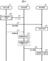
- the control unit 21 of the terminal device 20 transmits a beacon from the beacon antenna 26 at a predetermined cycle (step S31).
- the control unit 11 executes the position information detection process based on the beacon transmitted from the terminal device 20 (step S32).
- the control unit 11 when the control unit 11 executes the position information detection process, the control unit 11 transmits the detection information including the user's position information and the identification information of the corresponding terminal device 20 to the control device 30 (step S33).
- the control unit 31 receives the detection information transmitted from the detection device 10 and controls the air conditioning based on the received detection information (step S34). Since the processing of steps S32 to S34 is the same as that of steps S12 to S14 in the first embodiment, the description thereof will be omitted.
- control unit 11 transmits the detection information to the control device 30, and the image pickup unit 13 determines the direction detected by the direction detection unit 120 in the indoor space 2.
- the captured image obtained by imaging is transmitted to the terminal device 20 (step S35).
- control unit 21 receives the captured image transmitted from the detection device 10.
- the control unit 11 transmits the captured image to the terminal device 20 by communicating with the terminal device 20 via the communication unit 15. Alternatively, the control unit 11 may transmit the captured image together with the detection information to the control device 30, and transmit the captured image to the terminal device 20 via the control device 30.
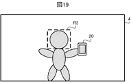
- the control unit 21 when the control unit 21 receives the captured image, the received captured image is displayed on the display unit 24 (step S36). For example, as shown in FIG. 19, the control unit 21 displays the captured image 4 in which the user holding the terminal device 20 is captured on the display unit 24. By displaying the captured image 4 on the terminal device 20 in this way, the user can confirm the state of the area including the place where he / she is in the indoor space 2.
- control unit 21 receives the selection of the air conditioning range from the user via the operation unit 23 (step S37).
- the user selects a range desired to be air-conditioned by the air conditioner 40 by operating the operation unit 23 while viewing the captured image displayed on the display unit 24.
- the control unit 21 accepts the user to select a range in which air conditioning is desired.
- the operation unit 23 functions as a selection receiving means.
- control unit 21 Upon receiving the selection of the air conditioning range, the control unit 21 transmits the selection information indicating the selected air conditioning range to the control device 30 (step S38). In the control device 30, the control unit 31 receives the selection information transmitted from the terminal device 20.
- the control unit 31 When the control device 30 receives the selection information, the control unit 31 functions as the air conditioning control unit 330, and causes the air conditioner 40 to air-condition the air-conditioning range according to the selection of the air-conditioning range shown in the received selection information (step S39). ..
- the air conditioning control unit 330 sends air conditioning air from the outlet of the indoor unit 42 toward the user's head. ..
- the air conditioning control unit 330 controls the wind direction so that the air conditioning air is sent to a wide range in the indoor space 2.
- the air conditioning system 1 according to the third embodiment displays the captured image on the terminal device 20. Then, the air conditioning system 1 according to the third embodiment accepts the selection of the air conditioning range from the user, and air-conditions the air conditioning range for which the selection is accepted. In this way, since the air conditioning is controlled based not only on the position information detected by the detection device 10 but also on the air conditioning range selected by the user, finer air conditioning control that reflects the user's request becomes possible. As a result, the comfort of the user can be further enhanced.
- the direction detection unit 120 determines from the beacon antenna 16 to the terminal device 20 by determining whether or not the intensity of the beacon received by the beacon antenna 16 having directivity is significantly lower than the threshold value. The direction to was detected. On the contrary, the direction detection unit 120 may detect the direction from the beacon antenna 16 to the terminal device 20 by determining whether or not the intensity of the received beacon has increased more than the threshold value. In this case, the direction detection unit 120 detects the direction from the outside to the inside of the beacon reception range R2 as the direction from the beacon antenna 16 to the terminal device 20 when the intensity of the received beacon rises more than the threshold value. ..
- the terminal device 20 transmits a beacon
- the detection device 10 receives the beacon transmitted from the terminal device 20 by a beacon antenna 16 having directivity within a range in which the beacon can be received.
- the detection device 10 is configured to emit a beacon by the beacon antenna 16 having directivity in a range in which the beacon can be transmitted
- the terminal device 20 is configured to receive the beacon by the beacon antenna 26. good. That is, the transmitting side and the receiving side of the beacon may be exchanged between the detection device 10 and the terminal device 20.
- the beacon transmitted from the detection device 10 is received by the terminal device 20 located inside the transmitting range of the beacon by the beacon antenna 16, but is located outside the transmitting range. It is not received by the terminal device 20.
- the terminal device 20 receives the beacon transmitted from the detection device 10
- the terminal device 20 transmits a signal including the identification information of the terminal device 20 to the detection device 10 as a response to the received beacon.
- the terminal device 20 may transmit the response to the beacon received from the detection device 10 as a beacon from the beacon antenna 26, or may be transmitted by a communication means other than the beacon by the communication unit 25.
- the detection device 10 receives the response transmitted from the terminal device 20 by the beacon antenna 16 or the communication unit 15.
- the direction detection unit 120 transfers the beacon antenna 16 to the terminal device 20 existing in the indoor space 2 based on the response to the beacon transmitted from the beacon antenna 16 when the beacon antenna 16 is rotating by the rotation drive unit 17. Detect the direction. Specifically, the terminal device 20 whose terminal device 20 is located inside the transmission range of the beacon by the beacon antenna 16 transmits a response to the beacon. Therefore, the direction detection unit 120 determines from the beacon antenna 16 to the terminal device 20 whether or not the response to the beacon transmitted while the beacon antenna 16 is rotating is interrupted or whether or not the response is started to be received. Detect the direction of. Even when the receiving side and the transmitting side of the beacon are exchanged in this way, the direction from the beacon antenna 16 to the terminal device 20 can be detected.
- the beacon transmitted / received between the detection device 10 and the terminal device 20 may be a beacon according to a standard other than BLE, such as an infrared beacon using infrared rays. Further, if the direction can be detected by receiving or transmitting with a directional antenna, a signal other than the beacon may be used.
- the detection device 10 is installed in the vicinity of the air-conditioned air outlet in the indoor unit 42.
- the space to be air-conditioned can be imaged by the imaging unit 13 and the beacon emitted from the space to be air-conditioned can be received by the beacon antenna 16, the detection device 10 is not limited to the indoor unit 42. It may be installed in a place.
- the detection device 10 and the control device 30 are separate devices.
- the detection device 10 may be integrated with the control device 30 as one air conditioning control device.
- the function provided in the detection device 10 and the function provided in the control device 30 are not limited to the above-described embodiment.
- the control device 30 may execute the processing of the direction detection unit 120 or the position information detection unit 130, or the preference data 340 may be stored in the detection device 10.
- the rotation drive unit 17 rotates the image pickup unit 13 and the beacon antenna 16 at the same time.
- the imaging unit 13 and the beacon antenna 16 are not limited to being rotated by one rotation driving unit 17 at the same time, and may be configured to be rotated separately by different rotation driving units.
- the configuration can be simplified and the cost can be suppressed.
- the imaging unit 13 does not rotate, and the range R1 imaged by the imaging unit 13 remains fixed. You may. In other words, it is possible that the rotation drive unit 17 does not rotate the image pickup unit 13 but only the beacon antenna 16.
- the position information detection unit 130 detects the distance from the indoor unit 42 to the user as position information based on the size of the user in the captured image.
- the position information detection unit 130 may detect the direction from the indoor unit 42 to the user as the position information based on the position of the user in the captured image.
- the detection information transmitted from the detection device 10 to the control device 30 does not have to include the direction information detected by the direction detection unit 120.
- the direction can be detected with higher accuracy than when the direction detection unit 120 detects the direction based on the change in the intensity of the beacon.
- the position information detection unit 130 may detect the distance from the indoor unit 42 to the user by using not only the captured image but also the beacon intensity information received by the beacon antenna 16.
- the position information detection unit 130 has an image obtained by the image pickup unit 13 capturing a region in the direction detected by the direction detection unit 120, and a beacon antenna 16 from the direction detected by the direction detection unit 120.
- the distance from the indoor unit 42 to the user may be detected based on the intensity of the beacon received by. Since the terminal device 20 transmits the beacon with a constant intensity, it can be determined that the distance to the user is closer when the intensity of the received beacon is stronger.
- the position information detection unit 130 sets the average value of the distance detected based on the captured image and the distance detected based on the beacon intensity from the indoor unit 42 to the user. It may be detected as a distance to. Alternatively, the position information detection unit 130 may detect the distance from the indoor unit 42 to the user from the distance detected based on the captured image and the distance detected based on the intensity of the beacon according to other rules. ..
- the air conditioning control unit 330 controls the air conditioning based on the user's position information detected by the position information detection unit 130.
- the air conditioning control unit 330 may further control the air conditioning based on the surface temperature of the user obtained from the captured image captured by the thermo camera.
- the air conditioning control unit 330 registers in advance the preferred surface temperature for each user as the preference data 340 in association with the identification information.
- the air conditioning control unit 330 adjusts the set temperature or the ventilation mode so that the surface temperature of the user obtained from the captured image approaches the surface temperature of the user's preference registered in advance in the preference data 340.
- the CPU executes a program stored in the ROM or the storage unit 12, so that the rotation control unit 110, the direction detection unit 120, the position information detection unit 130, and the detection information transmission unit 140 are executed. It functioned as each part of. Further, in the control unit 31, the CPU functions as each unit of the detection information receiving unit 310, the terminal communication unit 320, and the air conditioning control unit 330 by executing the program stored in the ROM or the storage unit 32.
- the control units 11 and 31 may be dedicated hardware.
- Dedicated hardware is, for example, a single circuit, a composite circuit, a programmed processor, an ASIC (Application Specific Integrated Circuit), an FPGA (Field-Programmable Gate Array), or a combination thereof.
- ASIC Application Specific Integrated Circuit
- FPGA Field-Programmable Gate Array
- control units 11 and 31 can realize each of the above-mentioned functions by hardware, software, firmware, or a combination thereof.
- the computer By applying an operation program that defines the operation of the detection device 10 or the control device 30 according to the present invention to an existing computer such as a personal computer or an information terminal device, the computer can be applied to the detection device 10 or the control device according to the present invention. It is also possible to make it function as 30.
- the distribution method of such a program is arbitrary, and for example, a computer-readable recording such as a CD-ROM (CompactDiskROM), a DVD (DigitalVersatileDisk), an MO (MagnetoOpticalDisk), or a memory card. It may be stored in a medium and distributed, or may be distributed via a communication network such as the Internet.
- a computer-readable recording such as a CD-ROM (CompactDiskROM), a DVD (DigitalVersatileDisk), an MO (MagnetoOpticalDisk), or a memory card. It may be stored in a medium and distributed, or may be distributed via a communication network such as the Internet.
- the present invention can be suitably adopted for an air conditioning system or the like.
- 1 air conditioner system 2 indoor space, 3, 4 captured image, 10 detector, 11 control unit, 12 storage unit, 13 imaging unit, 14 image processing unit, 15 communication unit, 16 beacon antenna, 17 rotation drive unit, 20 terminals Device, 21 control unit, 22 storage unit, 23 operation unit, 24 display unit, 25 communication unit, 26 beacon antenna, 30 control device, 31 control unit, 32 storage unit, 35 communication unit, 40 air conditioner, 41 outdoor unit, 42 indoor unit, 43 communication line, 44 outdoor unit control unit, 45 indoor unit control unit, 50 refrigerant circuit, 51 compressor, 52 four-way valve, 53 outdoor heat exchanger, 54 expansion valve, 55 indoor heat exchanger, 56 outdoor Fan, 57 indoor fan, 110 rotation control unit, 120 direction detection unit, 130 position information detection unit, 140 detection information transmission unit, 180 beacon data, 190 imaging data, 310 detection information reception unit, 320 terminal communication unit, 330 air conditioning control Department, 340 favorite data, R1 imaging range, R2 reception range, R3 air conditioning range
Landscapes
- Engineering & Computer Science (AREA)
- Physics & Mathematics (AREA)
- General Physics & Mathematics (AREA)
- Radar, Positioning & Navigation (AREA)
- Remote Sensing (AREA)
- Chemical & Material Sciences (AREA)
- Combustion & Propulsion (AREA)
- Mechanical Engineering (AREA)
- General Engineering & Computer Science (AREA)
- Air Conditioning Control Device (AREA)
Priority Applications (2)
| Application Number | Priority Date | Filing Date | Title |
|---|---|---|---|
| JP2021529605A JP7278378B2 (ja) | 2019-07-02 | 2019-07-02 | 空調用検出装置、空調制御装置、空調装置、空調システム及び空調方法 |
| PCT/JP2019/026330 WO2021001934A1 (ja) | 2019-07-02 | 2019-07-02 | 空調用検出装置、空調制御装置、空調装置、空調システム及び空調方法 |
Applications Claiming Priority (1)
| Application Number | Priority Date | Filing Date | Title |
|---|---|---|---|
| PCT/JP2019/026330 WO2021001934A1 (ja) | 2019-07-02 | 2019-07-02 | 空調用検出装置、空調制御装置、空調装置、空調システム及び空調方法 |
Publications (1)
| Publication Number | Publication Date |
|---|---|
| WO2021001934A1 true WO2021001934A1 (ja) | 2021-01-07 |
Family
ID=74100652
Family Applications (1)
| Application Number | Title | Priority Date | Filing Date |
|---|---|---|---|
| PCT/JP2019/026330 Ceased WO2021001934A1 (ja) | 2019-07-02 | 2019-07-02 | 空調用検出装置、空調制御装置、空調装置、空調システム及び空調方法 |
Country Status (2)
| Country | Link |
|---|---|
| JP (1) | JP7278378B2 (cg-RX-API-DMAC7.html) |
| WO (1) | WO2021001934A1 (cg-RX-API-DMAC7.html) |
Cited By (2)
| Publication number | Priority date | Publication date | Assignee | Title |
|---|---|---|---|---|
| JPWO2022264281A1 (cg-RX-API-DMAC7.html) * | 2021-06-15 | 2022-12-22 | ||
| JP2023161656A (ja) * | 2022-04-26 | 2023-11-08 | 清水建設株式会社 | 空調システム |
Citations (8)
| Publication number | Priority date | Publication date | Assignee | Title |
|---|---|---|---|---|
| JP2004354351A (ja) * | 2003-05-30 | 2004-12-16 | Sharp Corp | 電波発信器探索装置、携帯電話通信端末装置、及び電波発信器探索装置による電波発信器探索方法 |
| JP2009228910A (ja) * | 2008-03-19 | 2009-10-08 | Brother Ind Ltd | 空調制御システム |
| WO2014128784A1 (ja) * | 2013-02-20 | 2014-08-28 | パナソニック インテレクチュアル プロパティ コーポレーション オブ アメリカ | 携帯情報端末の制御方法及びプログラム |
| JP2016057030A (ja) * | 2014-09-12 | 2016-04-21 | 日立アプライアンス株式会社 | 空気調和機 |
| WO2017061429A1 (ja) * | 2015-10-05 | 2017-04-13 | 日本電気株式会社 | アンテナ指向制御信号生成装置と無線通信装置と無線通信制御システムとアンテナ指向性制御方法並びにプログラム |
| JP2017078608A (ja) * | 2015-10-19 | 2017-04-27 | 富士通株式会社 | 携帯端末装置、位置探索方法及び位置探索プログラム |
| US20180038949A1 (en) * | 2016-08-08 | 2018-02-08 | Lg Electronics Inc. | Occupancy detection apparatus and method for controlling the same |
| WO2018179750A1 (ja) * | 2017-03-28 | 2018-10-04 | パナソニックIpマネジメント株式会社 | 環境制御システム、及び、環境制御方法 |
Family Cites Families (2)
| Publication number | Priority date | Publication date | Assignee | Title |
|---|---|---|---|---|
| JP2015183964A (ja) | 2014-03-25 | 2015-10-22 | 日立アプライアンス株式会社 | 空気調和機、およびその室内機 |
| JP6852856B2 (ja) | 2017-07-06 | 2021-03-31 | 株式会社Where | 制御装置、制御方法、制御プログラム |
-
2019
- 2019-07-02 JP JP2021529605A patent/JP7278378B2/ja active Active
- 2019-07-02 WO PCT/JP2019/026330 patent/WO2021001934A1/ja not_active Ceased
Patent Citations (8)
| Publication number | Priority date | Publication date | Assignee | Title |
|---|---|---|---|---|
| JP2004354351A (ja) * | 2003-05-30 | 2004-12-16 | Sharp Corp | 電波発信器探索装置、携帯電話通信端末装置、及び電波発信器探索装置による電波発信器探索方法 |
| JP2009228910A (ja) * | 2008-03-19 | 2009-10-08 | Brother Ind Ltd | 空調制御システム |
| WO2014128784A1 (ja) * | 2013-02-20 | 2014-08-28 | パナソニック インテレクチュアル プロパティ コーポレーション オブ アメリカ | 携帯情報端末の制御方法及びプログラム |
| JP2016057030A (ja) * | 2014-09-12 | 2016-04-21 | 日立アプライアンス株式会社 | 空気調和機 |
| WO2017061429A1 (ja) * | 2015-10-05 | 2017-04-13 | 日本電気株式会社 | アンテナ指向制御信号生成装置と無線通信装置と無線通信制御システムとアンテナ指向性制御方法並びにプログラム |
| JP2017078608A (ja) * | 2015-10-19 | 2017-04-27 | 富士通株式会社 | 携帯端末装置、位置探索方法及び位置探索プログラム |
| US20180038949A1 (en) * | 2016-08-08 | 2018-02-08 | Lg Electronics Inc. | Occupancy detection apparatus and method for controlling the same |
| WO2018179750A1 (ja) * | 2017-03-28 | 2018-10-04 | パナソニックIpマネジメント株式会社 | 環境制御システム、及び、環境制御方法 |
Cited By (5)
| Publication number | Priority date | Publication date | Assignee | Title |
|---|---|---|---|---|
| JPWO2022264281A1 (cg-RX-API-DMAC7.html) * | 2021-06-15 | 2022-12-22 | ||
| WO2022264281A1 (ja) * | 2021-06-15 | 2022-12-22 | 日本電信電話株式会社 | 電波到来方向推定装置、電波到来方向推定方法、及び電波到来方向推定プログラム |
| JP7597218B2 (ja) | 2021-06-15 | 2024-12-10 | 日本電信電話株式会社 | 電波到来方向推定装置、電波到来方向推定方法、及び電波到来方向推定プログラム |
| JP2023161656A (ja) * | 2022-04-26 | 2023-11-08 | 清水建設株式会社 | 空調システム |
| JP7783123B2 (ja) | 2022-04-26 | 2025-12-09 | 清水建設株式会社 | 空調システム |
Also Published As
| Publication number | Publication date |
|---|---|
| JP7278378B2 (ja) | 2023-05-19 |
| JPWO2021001934A1 (cg-RX-API-DMAC7.html) | 2021-01-07 |
Similar Documents
| Publication | Publication Date | Title |
|---|---|---|
| JP5819271B2 (ja) | 空気調和機 | |
| JP6335425B2 (ja) | 空気調和機 | |
| CN107305035B (zh) | 空调机 | |
| CN105423502A (zh) | 空调送风控制方法及装置 | |
| JP2014047998A (ja) | 空気調和機 | |
| CN105546747A (zh) | 空调送风控制方法及装置 | |
| JP6972376B2 (ja) | 設置位置特定装置、空調システム、設置位置特定方法、および、プログラム | |
| JP2017048929A (ja) | 空気調和機 | |
| JP2015190666A (ja) | 空気調和機の室内機及びこれを用いた空気調和機 | |
| WO2017183083A1 (ja) | 空気調和システム | |
| JP6925530B2 (ja) | 空調装置、空調システム及び温度計測方法 | |
| JP2017187180A (ja) | 空気調和機 | |
| JP7278378B2 (ja) | 空調用検出装置、空調制御装置、空調装置、空調システム及び空調方法 | |
| CN113454403B (zh) | 空调装置 | |
| US20230408127A1 (en) | Identification device, equipment system, and identification method | |
| JP7374013B2 (ja) | 空調制御システム、空調システム、空調制御装置及び関連付け方法 | |
| JP7374217B2 (ja) | 空調制御システム、空調システム及び関連付け方法 | |
| JP7390946B2 (ja) | 空調制御装置、撮影装置、空調制御システム、空調システム及び空調制御方法 | |
| WO2021176553A1 (ja) | 人検知装置、人検知システム、設備機器システム、人検知方法及びプログラム | |
| JP7527363B2 (ja) | 制御システム、設備機器システム及び設備機器の制御方法 | |
| JPWO2021001934A5 (cg-RX-API-DMAC7.html) | ||
| JP6661798B2 (ja) | 空調システム及び空調方法 | |
| JP2014081144A (ja) | 空気調和機 | |
| WO2022054126A1 (ja) | 空調システム | |
| CN119492142B (zh) | 空调的控制方法、空调和计算机可读存储介质 |
Legal Events
| Date | Code | Title | Description |
|---|---|---|---|
| 121 | Ep: the epo has been informed by wipo that ep was designated in this application |
Ref document number: 19936448 Country of ref document: EP Kind code of ref document: A1 |
|
| ENP | Entry into the national phase |
Ref document number: 2021529605 Country of ref document: JP Kind code of ref document: A |
|
| NENP | Non-entry into the national phase |
Ref country code: DE |
|
| 122 | Ep: pct application non-entry in european phase |
Ref document number: 19936448 Country of ref document: EP Kind code of ref document: A1 |