WO2020262471A1 - 作業車両 - Google Patents
作業車両 Download PDFInfo
- Publication number
- WO2020262471A1 WO2020262471A1 PCT/JP2020/024856 JP2020024856W WO2020262471A1 WO 2020262471 A1 WO2020262471 A1 WO 2020262471A1 JP 2020024856 W JP2020024856 W JP 2020024856W WO 2020262471 A1 WO2020262471 A1 WO 2020262471A1
- Authority
- WO
- WIPO (PCT)
- Prior art keywords
- unit
- outrigger
- work vehicle
- outrigger unit
- cylinder
- Prior art date
- Legal status (The legal status is an assumption and is not a legal conclusion. Google has not performed a legal analysis and makes no representation as to the accuracy of the status listed.)
- Ceased
Links
Images





Classifications
-
- B—PERFORMING OPERATIONS; TRANSPORTING
- B66—HOISTING; LIFTING; HAULING
- B66C—CRANES; LOAD-ENGAGING ELEMENTS OR DEVICES FOR CRANES, CAPSTANS, WINCHES, OR TACKLES
- B66C23/00—Cranes comprising essentially a beam, boom, or triangular structure acting as a cantilever and mounted for translatory of swinging movements in vertical or horizontal planes or a combination of such movements, e.g. jib-cranes, derricks, tower cranes
- B66C23/62—Constructional features or details
- B66C23/72—Counterweights or supports for balancing lifting couples
- B66C23/78—Supports, e.g. outriggers, for mobile cranes
- B66C23/80—Supports, e.g. outriggers, for mobile cranes hydraulically actuated
-
- B—PERFORMING OPERATIONS; TRANSPORTING
- B66—HOISTING; LIFTING; HAULING
- B66C—CRANES; LOAD-ENGAGING ELEMENTS OR DEVICES FOR CRANES, CAPSTANS, WINCHES, OR TACKLES
- B66C23/00—Cranes comprising essentially a beam, boom, or triangular structure acting as a cantilever and mounted for translatory of swinging movements in vertical or horizontal planes or a combination of such movements, e.g. jib-cranes, derricks, tower cranes
- B66C23/62—Constructional features or details
- B66C23/72—Counterweights or supports for balancing lifting couples
- B66C23/78—Supports, e.g. outriggers, for mobile cranes
-
- B—PERFORMING OPERATIONS; TRANSPORTING
- B60—VEHICLES IN GENERAL
- B60S—SERVICING, CLEANING, REPAIRING, SUPPORTING, LIFTING, OR MANOEUVRING OF VEHICLES, NOT OTHERWISE PROVIDED FOR
- B60S9/00—Ground-engaging vehicle fittings for supporting, lifting, or manoeuvring the vehicle, wholly or in part, e.g. built-in jacks
- B60S9/02—Ground-engaging vehicle fittings for supporting, lifting, or manoeuvring the vehicle, wholly or in part, e.g. built-in jacks for only lifting or supporting
- B60S9/10—Ground-engaging vehicle fittings for supporting, lifting, or manoeuvring the vehicle, wholly or in part, e.g. built-in jacks for only lifting or supporting by fluid pressure
- B60S9/12—Ground-engaging vehicle fittings for supporting, lifting, or manoeuvring the vehicle, wholly or in part, e.g. built-in jacks for only lifting or supporting by fluid pressure of telescopic type
Definitions
- the present invention relates to a work vehicle.
- Patent Document 1 Conventionally, work vehicles equipped with outriggers on the front side and the rear side of the vehicle body are known (see, for example, Patent Document 1).
- Patent Document 1 discloses a pile driver including a front jack provided on the front side of the upper swing body and an outrigger jack provided on the rear side of the upper swing body.
- an object of the present invention is to provide a work vehicle that can be mounted on a trailer and transported without removing the outriggers.
- the work vehicle of the present invention A pair of outriggers that stabilize the posture of the work equipment, A unit that supports the pair of outriggers and is movably connected to the vehicle body of the work machine. An elevating part that moves the unit upward to raise the position of the lower end of the outrigger, Have.
- the work vehicle of the present invention configured in this way can be mounted on a trailer and transported without removing the outriggers.
- FIG. 1 It is a side view which shows the state which put the rough terrain crane of Example 1 on a low floor trailer. It is a perspective view which shows the rear outrigger main body of Example 1 from an oblique rear view. It is a top view which shows the rear outrigger main body and the elevating part of Example 1.
- FIG. It is a side view which shows the rear outrigger main body and the elevating part of Example 1.
- FIG. It is a side view which shows the state which the rear outrigger main body of Example 1 was raised and lowered.
- FIG. It is a side view which shows the state which the boom of Example 2 stood up and the front outrigger main body was raised. It is a side view which shows the state which the front outrigger main body of Example 2 was raised. It is a figure explaining the operation of the rough terrain crane of Example 2.
- the work vehicle of Example 1 is applied to a rough terrain crane.
- the work vehicle of the first embodiment is mounted on a low-floor trailer and transported.
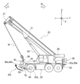
- FIG. 1 is a side view showing a state in which the rough terrain crane of the first embodiment is mounted on a low-floor trailer.
- the vehicle front-rear direction of the rough terrain crane 20 is the vehicle front-rear direction Y
- the vertical direction is the vertical direction Z
- the vehicle width direction is the vehicle width direction X.
- the front direction of the rough terrain crane 20 is the front F
- the rear direction of the rough terrain crane 20 is the rear R.
- the low-floor trailer 10 is towed by the tractor 12 as shown in FIG.
- the low-floor trailer 10 includes a low floor 11a, a first high floor 11b and a second high floor 11c as high portions.
- the first raised floor 11b is connected to the tractor 12.
- a low floor 11a lower than the first high floor 11b is connected to the front F of the first high floor 11b.
- a second raised floor 11c higher than the low floor 11a is connected to the front F of the low floor 11a. That is, the first raised floor 11b and the second raised floor 11c are located higher than the low floor 11a in the vertical direction Z.
- the rough terrain crane 20 as a work vehicle has a vehicle body 22 having a traveling function, a front outrigger unit 40 as an outrigger unit provided in the front F of the vehicle body 22, and a rear R of the vehicle body 22. It includes a rear outrigger unit 30 as an outrigger unit provided, a swivel base 23 attached so as to be able to turn horizontally with respect to the vehicle body 22, and a boom 21 attached to the swivel base 23.
- the front outrigger unit 40 is a unit that supports a pair of left and right front outriggers 40a and 40b and a pair of front outriggers 40a and 40b that stabilize the posture of the rough terrain crane 20 and is movably connected to the vehicle body of the rough terrain crane 20. 42 and.
- the rear outrigger unit 30 supports a pair of left and right rear outriggers 30a and 30b that stabilize the posture of the rough terrain crane 20 and a pair of rear outriggers 30a and 30b, and is movably connected to the vehicle body of the rough terrain crane 20. 42 and.
- the front outriggers 40a and 40b and the rear outriggers 30a and 30b can be expanded and contracted in the vehicle width direction X by expanding and contracting the slide cylinder.
- the front outriggers 40a and 40b and the rear outriggers 30a and 30b can be expanded and contracted in the vertical direction Z by expanding and contracting the jack cylinders 40c and 30c.
- the jack cylinder 30c has a cylinder tube 30d and a cylinder rod 30e that expands and contracts with respect to the cylinder tube 30d below the cylinder tube 30d (see FIG. 2).
- the jack cylinder 40c has a cylinder tube 40d and a cylinder rod 40e that expands and contracts with respect to the cylinder tube 40d below the cylinder tube 40d (see FIGS. 6 and 8).
- the vehicle body 22 includes a vehicle body frame 22a extending in the front-rear direction Y near the center of the vehicle width direction X.
- the swivel base 23 has a pinion gear to which the power of the swivel motor is transmitted, and the pinion gear meshes with a gear provided on the vehicle body 22 to rotate around the swivel shaft.
- the boom 21 is nested with a base end side boom 21a, intermediate booms 21b to 21d, and a tip end side boom 21e, and can be expanded and contracted by an expansion and contraction mechanism.
- the base end side boom 21a is rotatably attached to a support shaft extending in the vehicle width direction X, one end of which is attached to the swivel base 23.
- the base end side boom 21a can be raised and lowered with the support shaft as the center of rotation.
- An undulating cylinder 24 is bridged between the swivel base 23 and the base end side boom 21a, and the undulating cylinder 24 is expanded and contracted to undulate the boom 21.
- a rotatable sheave 27 is attached to the tip of the boom 21e on the tip side.
- a wire W is hung around the sheave 27.
- a hook 28 is attached to one end of the wire W.
- the other end of the wire W is wound around the winch 29, and the wire W can be wound up or down by rotating the winch 29.
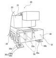
- FIG. 2 is a perspective view showing the rear outrigger unit of the first embodiment diagonally from the rear.
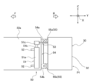
- FIG. 3 is a plan view showing the rear outrigger unit and the elevating part of the first embodiment.
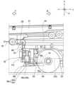
- FIG. 4 is a side view showing the rear outrigger unit and the elevating part of the first embodiment.
- FIG. 5 is a side view showing a state in which the rear outrigger unit of the first embodiment is raised and lowered.
- the elevating part 50 is arranged between the vehicle body 22 and the rear outrigger unit 30, and raises and lowers the rear outrigger unit 30 so as to elevate the entire jack cylinder 30c with respect to the vehicle body 22.
- the elevating portion 50 raises the position of the lower end portions of the rear outriggers 30a and 30b by moving the unit 32 upward.
- the elevating unit 50 includes two elevating cylinders 51.
- the elevating cylinder 51 includes a cylinder body 51a (functioning as a "cylinder” of the present invention) and a rod portion 51b (functioning as a "rod” of the present invention) that is fitted into the cylinder body 51a and slidable with respect to the cylinder body 51a.
- the rod tip portion 51c attached to the tip of the rod portion 51b is provided.
- the elevating cylinder 51 expands and contracts as the rod portion 51b slides with respect to the cylinder body 51a.
- the cylinder body 51a is attached to both side surfaces of the vehicle body frame 22a in the vehicle width direction X by two attachment brackets 52.
- a connecting portion 53 that supports the unit 32 is attached to the rod tip portion 51c.
- the connecting portion 53 connects the rod tip portion 51c and the rear outrigger unit 30 (unit 32).
- first brackets 54 are attached to the rear end of the vehicle body frame 22a.
- the first bracket 54 is a plate-shaped member extending in the vertical direction Z, and is formed so as to project rearwardly from the rear end of the vehicle body frame 22a.
- the two first brackets 54 are arranged so as to sandwich the one second bracket 55.
- a tongue-shaped upper end 54a is formed at the upper end of the first bracket 54.
- a tongue-shaped lower end 54b is formed at the lower end of the first bracket 54.
- the upper end portion 54a and the lower end portion 54b each have a through hole penetrating in the vehicle width direction X.
- Two second brackets 55 are attached to the front end of the rear outrigger unit 30 (unit 32).
- the second bracket 55 is a plate-shaped member, and has a tongue-shaped upper edge portion 55a formed near the upper end of the rear outrigger unit 30 (unit 32) and a tongue-shaped lower edge portion 55b formed near the lower end portion. To be equipped.
- the upper edge portion 55a and the lower edge portion 55b are formed so as to extend from the front end of the rear outrigger unit 30 (unit 32) to the front F.
- One second bracket 55 is arranged so as to be sandwiched between the two first brackets 54.
- the upper edge portion 55a and the lower edge portion 55b have through holes penetrating in the vehicle width direction X.
- the elevating unit 50 configured in this way causes the elevating cylinder 51 to contract, so that the rear outrigger unit 30 (unit 32) moves to the descending position P1.
- a common insertion pin is inserted into both through holes in a state where the through hole of the upper end portion 54a of the first bracket 54 and the through hole of the upper edge portion 55a of the second bracket 55 are aligned in the vertical direction Z.
- a common insertion pin is inserted into both through holes in a state where the through hole of the lower end portion 54b of the first bracket 54 and the through hole of the lower edge portion 55b of the second bracket 55 are aligned in the vertical direction Z.
- the rear outrigger unit 30 (unit 32) rises in the vertical direction (vertical direction) Z along the first bracket 54 provided on the vehicle body frame 22a. Move to the ascending position P2. Then, a common insertion pin is inserted into both through holes in a state where the through holes of the upper end portion 54a of the first bracket 54 and the through holes of the lower edge portion 55b of the second bracket 55 are aligned in the vertical direction Z. By doing so, the rear outrigger unit 30 (unit 32) is fixed at the ascending position P2.
- the elevating cylinder 51 raises and lowers the rear outrigger unit 30 (unit 32) in the vertical direction (vertical direction) Z.
- the work vehicle (rough terrain crane 20) of the first embodiment has a low floor 11a and a low floor having a high portion (first high floor 11b, second high floor 11c) higher than the low floor 11a on the front side and the rear side of the low floor 11a.
- a work vehicle (rough terrain crane 20) mounted on the trailer 10 and transported to the vehicle body 22 with the outrigger units (front outrigger unit 40, rear outrigger unit 30) attached to the front and rear of the vehicle body 22.
- the outrigger unit (front outrigger unit 40, rear outrigger unit 30) is provided with an elevating portion 50 for raising and lowering (FIG. 1).
- the outrigger units front outrigger unit 40, rear outrigger unit 30
- the ascending position P2 which is raised from the descending position P1.
- the approach angle or departure angle of the work vehicle (rough terrain crane 20) can be improved.
- the approach angle is the minimum angle formed by the tangent line drawn from the lower end of the front portion of the work vehicle to the outer circumference of the front wheel tires with the ground.
- the departure angle is the minimum angle formed by the tangent line drawn from the lower end of the rear part of the work vehicle to the outer circumference of the rear wheel tires with the ground.
- the outrigger units front outrigger unit 40, rear outrigger unit 30
- the outrigger units are mounted on the high portion (first) of the low floor trailer 10. It can be prevented from interfering with the 1st raised floor 11b and the 2nd raised floor 11c). Therefore, the work vehicle (rough terrain crane 20) can be transported by a trailer smaller than the conventional one.
- the outrigger units front outrigger unit 40, rear outrigger unit 30
- the outrigger units front outrigger unit 40, rear outrigger unit 30
- the outrigger units front outrigger unit 40, rear outrigger unit 30
- the elevating unit 50 includes an elevating cylinder 51 that elevates and elevates the outrigger units (front outrigger unit 40, rear outrigger unit 30) in the vertical direction (FIGS. 4 and 5). ..
- the outrigger units front outrigger unit 40, rear outrigger unit 30
- the elevating cylinder 51 the elevating cylinder 51. Therefore, the outrigger units (front outrigger unit 40, rear outrigger unit 30) can be raised and lowered quickly and easily.
- the work vehicle of the second embodiment is different from the work vehicle of the first embodiment in that the configuration of the elevating part is different.
- FIG. 6 is a side view showing the front outrigger unit and the elevating part of the second embodiment.
- FIG. 7 is a side view showing a state in which the boom of the second embodiment stands up and the front outrigger unit rises.
- FIG. 8 is a side view showing a state in which the front outrigger unit of the second embodiment is raised.
- the configuration of the elevating part of the second embodiment will be described with reference to FIGS. 6 to 8. The same or equivalent parts as those described in the above examples will be described using the same terms or the same reference numerals.
- the front outrigger unit 40 (unit 42) includes an annular portion 61 formed so as to extend upward from the upper surface of the front outrigger unit 40.
- the annular portion 61 (functioning as an “engaging portion” of the present invention) can be attached with a hook 28 suspended by a wire W via a sheave 27 provided at the tip of a boom 21e on the tip end side.
- a rotating shaft 62 extending in the vehicle width direction X is attached to the upper part of the rear side of the front outrigger unit 40 (unit 42).
- the rotating shaft 62 is fixed to the front side of the vehicle body frame 22a.
- the front outrigger unit 40 is configured to be rotatable around the rotation shaft 62 in the undulating direction of the boom 21.
- a mounting shaft 63 extending in the vehicle width direction X is provided at the lower part on the rear side of the front outrigger unit 40 (unit 42).
- a mounting shaft 64 extending in the vehicle width direction X is provided in the lower portion on the front side of the vehicle body frame 22a.
- the front outrigger unit 40 and the vehicle body frame 22a are connected by attaching one end of the connecting member 70 to the mounting shaft 63 of the front outrigger unit 40 and attaching the other end of the connecting member 70 to the mounting shaft 64 of the vehicle body frame 22a.
- the connecting member 70 has an inner cylinder 70a and an outer cylinder 70b.
- the inner cylinder 70a is slidable with respect to the outer cylinder 70b.
- the connecting member 70 is configured to be expandable and contractible by an external force.
- a plurality of through holes are formed in the inner cylinder 70a and the outer cylinder 70b in the axial direction (longitudinal direction), respectively.
- the connecting member 70 can be fixed to a predetermined length by inserting a common pin in a state where the through hole of the inner cylinder 70a and the through hole of the outer cylinder 70b match.
- the front outrigger unit 40 (unit 42) is located at the descending position P3 in the initial state.
- the boom 21 is raised and the wire W is wound up by the winch 29 to raise the hook 28.
- the front outrigger unit 40 (unit 42) moves to the ascending position P4 which is rotated upward in conjunction with the lifting operation of the rough terrain crane 20 about the rotating shaft 62.
- the front outrigger unit 40 (unit 42) is fixed to the ascending position P4 by inserting the pins into the through holes of the inner cylinder 70a and the outer cylinder 70b of the connecting member 70.
- the boom 21 is brought down. In this state, the rough terrain crane 20 is placed on a low-floor trailer and transported.
- the boom 21, winch 29, hook 28, and rotating shaft 62 raise and lower the front outrigger unit 40 (unit 42) by rotating the front outrigger unit 40 (unit 42) in the undulating direction of the boom 21 so as to raise and lower the entire jack cylinder 40c.
- Part 60 is configured.
- the elevating portion 60 raises the position of the lower end portions of the front outriggers 40a and 40b by rotating the unit 42 around the rotation shaft 62 and moving it upward.
- FIG. 9 is a diagram illustrating the operation of the rough terrain crane 20 of the second embodiment.
- the operation of the work vehicle (rough terrain crane 20) of the second embodiment will be described with reference to FIG.
- the elevating part 60 includes a rotating shaft 62 extending in the vehicle width direction X above the outrigger units (front outrigger unit 40, rear outrigger unit 30) (FIG. 6).
- the outrigger units (front outrigger unit 40, rear outrigger unit 30) can be rotated upward around the rotation shaft 62 to move from the descending position P3 to the ascending position P4. Therefore, rather than raising the outrigger units (front outrigger unit 40, rear outrigger unit 30) in the vertical direction, the work vehicle (rough terrain crane 20) suppresses the rise of the outrigger units (front outrigger unit 40, rear outrigger unit 30). ) Approach angle or departure angle can be increased. As a result, even when a boom or the like is arranged above the outrigger units (front outrigger unit 40, rear outrigger unit 30), the approach angle or departure angle of the work vehicle (rough terrain crane 20) can be adjusted. It can be made larger.
- the outrigger unit (front outrigger unit 40, rear outrigger unit 30) has an annular portion 61 to which a hook 28 suspended by a wire W is attached from the tip of the boom 21. (Fig. 6).
- the outrigger unit (front outrigger unit 40, rear outrigger unit 30) is rotated upward by hooking the hook 28 on the annular portion 61 and winding up the wire W by the winch 29 in a state where the boom 21 is undulating. Can be done. Therefore, the outrigger units (front outrigger unit 40, rear outrigger unit 30) can be rotated upward by using the existing parts of a general crane. As a result, the approach angle or departure angle can be improved with a simple configuration.
- the outrigger units front outrigger unit 40, rear outrigger unit 30
- the elevating unit 60 and the outrigger units (front outrigger unit 40, rear outrigger unit 30).
- the vehicle body 22 are provided with a connecting member 70 (FIG. 6).
- the outrigger units (front outrigger unit 40, rear outrigger unit 30) at the ascending position P4 can be fixed by the connecting member 70. Therefore, the outrigger units (front outrigger unit 40, rear outrigger unit 30) at the ascending position P4 can be fixed with a simple configuration.
- the front outrigger unit 40 is moved up and down in the vertical direction by the elevating part 50 is shown.
- the rear outrigger unit 30 may also be raised and lowered in the vertical direction by the raising and lowering portion 50.
- the rear outrigger unit 30 is moved up and down by the elevating part 60 by rotating the rotating shaft 62 as an axis.
- the front outrigger unit may also be moved up and down by rotating the rotating shaft as an axis by the elevating part.
- the elevating part may be in a mode in which the rear outrigger unit 30 and the front outrigger unit 40 can be raised and lowered, and the rear outrigger unit 30 and the front outrigger unit 40 may be raised and lowered by, for example, a link mechanism.
- Example 1 an example was shown in which the rear outrigger unit 30 was fixed to the vehicle body frame 22a by inserting an insertion pin into the through hole of the second bracket and the through hole of the first bracket.
- the rear outrigger unit 30 may be fixed to the vehicle body frame 22a by inserting an insertion pin into the through hole of the second bracket and the through hole of the first bracket using the telescopic cylinder.
- the low-floor trailer 10 includes a low-floor 11a, a first high-floor 11b and a second high-floor 11c arranged in front of and behind the low-floor 11a.
- the low-floor trailer is not limited to this embodiment, and may have a high floor on either the front side or the rear side of the low floor, for example.
- the connecting member 70 is configured to be expandable and contractible by an external force.
- the connecting portion may be any one that connects the front outrigger unit 40 and the vehicle body 22 in a state where the front outrigger unit 40 (unit 42) is located at the ascending position P4.
- the work vehicle of the present invention can also be applied to an all-terrain crane, a cargo crane, a truck crane, an aerial work platform, and other construction vehicles.
Landscapes
- Engineering & Computer Science (AREA)
- Mechanical Engineering (AREA)
- Physics & Mathematics (AREA)
- Fluid Mechanics (AREA)
- Jib Cranes (AREA)
- Vehicle Cleaning, Maintenance, Repair, Refitting, And Outriggers (AREA)
Abstract
アウトリガを取り外すことなく、トレーラに載置して搬送可能な作業車両を提供する。作業車両は、低床(11a)と、低床(11a)の前側及び後側の少なくとも一方に低床(11a)より高い高部(第1高床(11b),第2高床(11c))を備える低床トレーラ(10)に載置されて、搬送される作業車両(ラフテレーンクレーン(20))であって、車体(22)の前後に取り付けられたアウトリガユニット(フロントアウトリガユニット(40),リアアウトリガユニット(30))と、車体22に対して、アウトリガユニット(フロントアウトリガユニット(40),リアアウトリガユニット(30))を昇降させる昇降部(50)と、を備える。
Description
本発明は、作業車両に関する。
従来、車体の前側と後側にアウトリガを備えた作業車両が知られている(例えば、特許文献1参照)。
特許文献1には、上部旋回体の前側に設けられたフロントジャッキと、上部旋回体の後側に設けられたアウトリガジャッキと、を備えた杭打機が開示されている。
しかしながら、特許文献1の構成のように、トレーラに作業車両を載置して搬送する際に、アウトリガを取り外さなくてはならない、という問題がある。
そこで、本発明は、アウトリガを取り外すことなく、トレーラに載置して搬送可能な作業車両を提供することを目的とする。
前記目的を達成するために、本発明の作業車両は、
作業機の姿勢を安定させる、一対のアウトリガと、
前記一対のアウトリガを支持し、前記作業機の車体に移動可能に連結されたユニットと、
前記ユニットを上方に移動させて、前記アウトリガの下端部の位置を上昇させる昇降部と、
を有する。
作業機の姿勢を安定させる、一対のアウトリガと、
前記一対のアウトリガを支持し、前記作業機の車体に移動可能に連結されたユニットと、
前記ユニットを上方に移動させて、前記アウトリガの下端部の位置を上昇させる昇降部と、
を有する。
このように構成された本発明の作業車両は、アウトリガを取り外すことなく、トレーラに載置して搬送することができる。
以下、本発明による作業車両を実現する実施形態を、図面に示す実施例1及び実施例2に基づいて説明する。
実施例1の作業車両は、ラフテレーンクレーンに適用される。実施例1の作業車両は、低床トレーラに載置されて搬送される。
[低床トレーラの構成]
図1は、実施例1のラフテレーンクレーンを低床トレーラに載置した状態を示す側面図である。以下、図1に基づいて、実施例1の低床トレーラの構成を説明する。なお、ラフテレーンクレーン20の車両前後方向を前後方向Yとし、上下方向を上下方向Zとし、車両幅方向を車幅方向Xとする。また、前後方向Yのうち、ラフテレーンクレーン20の前方向を前方Fとし、ラフテレーンクレーン20の後方向を後方Rとする。
図1は、実施例1のラフテレーンクレーンを低床トレーラに載置した状態を示す側面図である。以下、図1に基づいて、実施例1の低床トレーラの構成を説明する。なお、ラフテレーンクレーン20の車両前後方向を前後方向Yとし、上下方向を上下方向Zとし、車両幅方向を車幅方向Xとする。また、前後方向Yのうち、ラフテレーンクレーン20の前方向を前方Fとし、ラフテレーンクレーン20の後方向を後方Rとする。
低床トレーラ10は、図1に示すように、トラクター12に牽引される。低床トレーラ10は、低床11aと、高部としての第1高床11bと第2高床11cと、を備える。
第1高床11bは、トラクター12に連結される。第1高床11bの前方Fに、第1高床11bより低い低床11aが接続される。低床11aの前方Fに、低床11aより高い第2高床11cが接続される。すなわち、第1高床11bと第2高床11cは、上下方向Zにおいて、低床11aより高い位置にある。
[ラフテレーンクレーンの構成]
以下、図1に基づいて、実施例1のラフテレーンクレーンの構成を説明する。
以下、図1に基づいて、実施例1のラフテレーンクレーンの構成を説明する。
作業車両としてのラフテレーンクレーン20は、図1に示すように、走行機能を有する車体22と、車体22の前方Fに設けられたアウトリガユニットとしてのフロントアウトリガユニット40と、車体22の後方Rに設けられたアウトリガユニットとしてのリアアウトリガユニット30と、車体22に対して水平旋回可能に取り付けられた旋回台23と、旋回台23に取り付けられたブーム21と、を備える。
フロントアウトリガユニット40は、ラフテレーンクレーン20の姿勢を安定させる左右一対のフロントアウトリガ40a,40bと、一対のフロントアウトリガ40a,40bを支持し、ラフテレーンクレーン20の車体に移動可能に連結されたユニット42とを備える。リアアウトリガユニット30は、ラフテレーンクレーン20の姿勢を安定させる左右一対のリアアウトリガ30a,30bと、一対のリアアウトリガ30a,30bを支持し、ラフテレーンクレーン20の車体に移動可能に連結されたユニット42とを備える。フロントアウトリガ40a,40bとリアアウトリガ30a,30bは、スライドシリンダを伸縮させることによって、車幅方向Xに伸縮可能である。また、フロントアウトリガ40a,40bとリアアウトリガ30a,30bは、ジャッキシリンダ40c,30cを伸縮させることによって、上下方向Zに伸縮可能である。ジャッキシリンダ30cは、シリンダチューブ30dと、シリンダチューブ30dの下方でシリンダチューブ30dに対して伸縮するシリンダロッド30eとを有する(図2を参照)。ジャッキシリンダ40cは、シリンダチューブ40dと、シリンダチューブ40dの下方でシリンダチューブ40dに対して伸縮するシリンダロッド40eとを有する(図6,8を参照)。
車体22は、車幅方向Xの中央付近に、前後方向Yに延在して設けられる車体フレーム22aを備える。
旋回台23は、旋回用モータの動力が伝達されるピニオンギヤを有しており、このピニオンギヤが車体22に設けたギヤに噛み合うことで旋回軸を中心に回動する。
ブーム21は、基端側ブーム21aと、中間ブーム21b~21dと、先端側ブーム21eとによって入れ子式に構成され、伸縮機構により伸縮可能になっている。
基端側ブーム21aは、一端が旋回台23に取り付けられた、車幅方向Xに延在した支持軸に回動自在に取り付けられる。基端側ブーム21aは、この支持軸を回動中心として、上下に起伏できるようになっている。旋回台23と基端側ブーム21aとの間には、起伏シリンダ24が架け渡されており、起伏シリンダ24を伸縮することで、ブーム21を起伏するようになっている。
先端側ブーム21eの先端には、回転自在のシーブ27が取り付けられる。シーブ27には、ワイヤWが掛け回されている。ワイヤWの一端には、フック28が取り付けられる。ワイヤWの他端は、ウインチ29に巻き回されており、ウインチ29を回転させることでワイヤWを巻き上げたり、巻き下げたりすることができる。
[昇降部の構成]
図2は、実施例1のリアアウトリガユニットを斜め後方から示す斜視図である。図3は、実施例1のリアアウトリガユニットと昇降部を示す平面図である。図4は、実施例1のリアアウトリガユニットと昇降部を示す側面図である。図5は、実施例1のリアアウトリガユニットが昇降した状態を示す側面図である。以下、図2~図5に基づいて、実施例1の昇降部の構成を説明する。
図2は、実施例1のリアアウトリガユニットを斜め後方から示す斜視図である。図3は、実施例1のリアアウトリガユニットと昇降部を示す平面図である。図4は、実施例1のリアアウトリガユニットと昇降部を示す側面図である。図5は、実施例1のリアアウトリガユニットが昇降した状態を示す側面図である。以下、図2~図5に基づいて、実施例1の昇降部の構成を説明する。
昇降部50は、図2に示すように、車体22と、リアアウトリガユニット30との間に配置され、車体22に対して、ジャッキシリンダ30cの全体を昇降させるようリアアウトリガユニット30を昇降させる。昇降部50は、ユニット32を上方に移動させることにより、リアアウトリガ30a,30bの下端部の位置を上昇させる。
昇降部50は、図3及び図4に示すように、2つの昇降シリンダ51を備える。昇降シリンダ51は、シリンダ本体51a(本発明の「シリンダ」として機能)と、シリンダ本体51aに嵌挿されシリンダ本体51aに対してスライド可能なロッド部51b(本発明の「ロッド」として機能)と、ロッド部51bの先端に取り付けられるロッド先端部51cと、を備える。
昇降シリンダ51は、シリンダ本体51aに対して、ロッド部51bがスライドすることにより、伸縮する。
シリンダ本体51aは、2つの取付ブラケット52によって、車幅方向Xにおいて、車体フレーム22aの両側面に取り付けられる。
ロッド先端部51cには、ユニット32を支持する連結部53が取り付けられる。連結部53は、ロッド先端部51cと、リアアウトリガユニット30(ユニット32)とを連結する。
車体フレーム22aの後端には、4つの第1ブラケット54(本発明の「ガイド部」として機能)が取り付けられる。
第1ブラケット54は、上下方向Zに延在する板状部材であり、車体フレーム22aの後端から、後方Rに突出して形成される。2つの第1ブラケット54は、1つの第2ブラケット55を挟むように配置される。
第1ブラケット54の上端には、舌状の上端部54aが形成される。第1ブラケット54の下端には、舌状の下端部54bが形成される。上端部54aと下端部54bは、それぞれ、車幅方向Xに貫通した貫通穴を有する。
リアアウトリガユニット30(ユニット32)の前端には、2つの第2ブラケット55が取り付けられる。
第2ブラケット55は、板状部材であり、リアアウトリガユニット30(ユニット32)の上端付近に形成される舌状の上縁部55aと、下端付近に形成される舌状の下縁部55bとを備える。
上縁部55aと下縁部55bは、リアアウトリガユニット30(ユニット32)の前端から、前方Fに延在して形成される。1つの第2ブラケット55は、2つの第1ブラケット54で挟まれるように配置される。上縁部55aと下縁部55bは、車幅方向Xに貫通した貫通穴を有する。
このように構成された昇降部50により、図4に示すように、昇降シリンダ51が縮むことで、リアアウトリガユニット30(ユニット32)が下降位置P1に移動する。そして、第1ブラケット54の上端部54aの貫通穴と、第2ブラケット55の上縁部55aの貫通穴との上下方向Zの位置が一致した状態で、両貫通穴に共通の挿入ピンが挿入され、第1ブラケット54の下端部54bの貫通穴と、第2ブラケット55の下縁部55bの貫通穴との上下方向Zの位置が一致した状態で、両貫通穴に共通の挿入ピンが挿入されることで、リアアウトリガユニット30(ユニット32)が下降位置P1に固定される。
また、図5に示すように、昇降シリンダ51が伸びることで、リアアウトリガユニット30(ユニット32)が車体フレーム22aに設けられた第1ブラケット54に沿って上下方向(垂直方向)Zに上昇した上昇位置P2に移動する。そして、第1ブラケット54の上端部54aの貫通穴と、第2ブラケット55の下縁部55bの貫通穴との上下方向Zの位置が一致した状態で、両貫通穴に共通の挿入ピンが挿入されることで、リアアウトリガユニット30(ユニット32)が上昇位置P2に固定される。
すなわち、昇降シリンダ51は、リアアウトリガユニット30(ユニット32)を上下方向(垂直方向)Zに昇降させる。
[作業車両の作用]
以下、実施例1の作業車両(ラフテレーンクレーン20)の作用を説明する。実施例1の作業車両(ラフテレーンクレーン20)は、低床11aと、低床11aの前側及び後側に低床11aより高い高部(第1高床11b,第2高床11c)を備える低床トレーラ10に載置されて、搬送される作業車両(ラフテレーンクレーン20)であって、車体22の前後に取り付けられたアウトリガユニット(フロントアウトリガユニット40,リアアウトリガユニット30)と、車体22に対して、アウトリガユニット(フロントアウトリガユニット40,リアアウトリガユニット30)を昇降させる昇降部50と、を備える(図1)。
以下、実施例1の作業車両(ラフテレーンクレーン20)の作用を説明する。実施例1の作業車両(ラフテレーンクレーン20)は、低床11aと、低床11aの前側及び後側に低床11aより高い高部(第1高床11b,第2高床11c)を備える低床トレーラ10に載置されて、搬送される作業車両(ラフテレーンクレーン20)であって、車体22の前後に取り付けられたアウトリガユニット(フロントアウトリガユニット40,リアアウトリガユニット30)と、車体22に対して、アウトリガユニット(フロントアウトリガユニット40,リアアウトリガユニット30)を昇降させる昇降部50と、を備える(図1)。
これにより、作業車両(ラフテレーンクレーン20)を低床トレーラ10に載せたり降ろしたりする際、アウトリガユニット(フロントアウトリガユニット40,リアアウトリガユニット30)を、下降位置P1より上昇させた上昇位置P2にすることができる。その結果、作業車両(ラフテレーンクレーン20)のアプローチアングル又はデパーチャアングルを改善することができる。なお、アプローチアングルとは、作業車両の前部下端から前輪タイヤ外周に引いた接線が地面となす最小角度のことである。デパーチャアングルとは、作業車両の後部下端から後輪タイヤ外周に引いた接線が地面となす最小角度のことである。
そして、アウトリガユニット(フロントアウトリガユニット40,リアアウトリガユニット30)を取り外すことなく、図1に示すように、アウトリガユニット(フロントアウトリガユニット40,リアアウトリガユニット30)を低床トレーラ10の高部(第1高床11b,第2高床11c)に干渉させないようにすることができる。そのため、作業車両(ラフテレーンクレーン20)を、従来より小型のトレーラで搬送することができる。
また、作業車両(ラフテレーンクレーン20)が急斜面を走行する際に、アウトリガユニット(フロントアウトリガユニット40,リアアウトリガユニット30)を車体22に対して上昇させることができる。そのため、アウトリガユニット(フロントアウトリガユニット40,リアアウトリガユニット30)を取り外すことなく、アウトリガユニット(フロントアウトリガユニット40,リアアウトリガユニット30)を路面に干渉させないようにすることができる。
実施例1の作業車両(ラフテレーンクレーン20)において、昇降部50は、アウトリガユニット(フロントアウトリガユニット40,リアアウトリガユニット30)を垂直方向に昇降させる昇降シリンダ51を備える(図4,図5)。
これにより、アウトリガユニット(フロントアウトリガユニット40,リアアウトリガユニット30)を、昇降シリンダ51によって昇降させることができる。そのため、アウトリガユニット(フロントアウトリガユニット40,リアアウトリガユニット30)の昇降を、素早く、かつ、容易に実行することができる。
実施例2の作業車両は、昇降部の構成が異なる点で、実施例1の作業車両と相違する。
[昇降部の構成]
図6は、実施例2のフロントアウトリガユニットと昇降部を示す側面図である。図7は、実施例2のブームが起立してフロントアウトリガユニットが上昇した状態を示す側面図である。図8は、実施例2のフロントアウトリガユニットが上昇した状態を示す側面図である。以下、図6~図8に基づいて、実施例2の昇降部の構成を説明する。なお、上記実施例で説明した内容と同一乃至均等な部分の説明については、同一用語又は同一の符号を用いて説明する。
図6は、実施例2のフロントアウトリガユニットと昇降部を示す側面図である。図7は、実施例2のブームが起立してフロントアウトリガユニットが上昇した状態を示す側面図である。図8は、実施例2のフロントアウトリガユニットが上昇した状態を示す側面図である。以下、図6~図8に基づいて、実施例2の昇降部の構成を説明する。なお、上記実施例で説明した内容と同一乃至均等な部分の説明については、同一用語又は同一の符号を用いて説明する。
図6に示すように、フロントアウトリガユニット40(ユニット42)は、フロントアウトリガユニット40の上面から上方に延在して形成された環状の環状部61を備える。環状部61(本発明の「係合部」として機能)は、先端側ブーム21eの先端に設けられたシーブ27を介して、ワイヤWによって吊り下げられたフック28が取り付け可能となっている。
フロントアウトリガユニット40(ユニット42)の後側の上部には、車幅方向Xに延在する、回転軸62が取り付けられる。回転軸62は、車体フレーム22aの前側に固定される。フロントアウトリガユニット40は、回転軸62を軸として、ブーム21の起伏方向に回動可能に構成される。
フロントアウトリガユニット40(ユニット42)の後側の下部には、車幅方向Xに延在する取付軸63を備える。車体フレーム22aの前側の下部には、車幅方向Xに延在する取付軸64を備える。フロントアウトリガユニット40の取付軸63に連結部材70の一端が取り付けられ、車体フレーム22aの取付軸64に連結部材70の他端が取り付けられることで、フロントアウトリガユニット40と車体フレーム22aとが連結される。
連結部材70は、内筒70aと外筒70bを有する。内筒70aは、外筒70bに対してスライド可能となっている。連結部材70は、外力によって伸縮可能に構成される。
内筒70aと外筒70bは、それぞれ、軸方向(長手方向)に複数の貫通穴が形成される。内筒70aの貫通穴と外筒70bの貫通穴とが一致した状態で、共通のピンを挿入することで、連結部材70を所定の長さに固定することができる。
このように構成されたラフテレーンクレーン20は、図6に示すように、初期状態では、フロントアウトリガユニット40(ユニット42)が下降位置P3に位置する。
図7に示すように、ブーム21を起立させ、ワイヤWをウインチ29によって巻き上げることで、フック28を上昇させる。これにより、フロントアウトリガユニット40(ユニット42)が回転軸62を軸として、ラフテレーンクレーン20の吊り上げ動作に連動して上方に回転した上昇位置P4に移動する。そして、連結部材70の内筒70aと外筒70bの貫通穴にピンが挿入されることで、フロントアウトリガユニット40(ユニット42)が上昇位置P4に固定される。次いで、ブーム21を倒した状態にする。この状態で、ラフテレーンクレーン20は、低床トレーラに載置されて搬送される。
フロントアウトリガユニット40(ユニット42)が上昇位置P4から下降位置P3に移動する際には、ブーム21を起立させ、フロントアウトリガユニット40をフック28で保持しながら、連結部材70の内筒70aと外筒70bの貫通穴に挿入されているピンを抜く。そして、ワイヤWをウインチ29によって巻き下げることで、フック28を下降させて、フロントアウトリガユニット40(ユニット42)を、図6に示す下降位置P3に移動する。そして、連結部材70の内筒70aと外筒70bの貫通穴にピンが挿入されることで、フロントアウトリガユニット40(ユニット42)が下降位置P3に固定される。
ブーム21と、ウインチ29と、フック28と、回転軸62とは、ジャッキシリンダ40cの全体を昇降させるようフロントアウトリガユニット40(ユニット42)を、ブーム21の起伏方向に回転させることで昇降させる昇降部60を構成する。昇降部60は、回転軸62まわりにユニット42を回転させて上方に移動させることにより、フロントアウトリガ40a,40bの下端部の位置を上昇させる。
[作業車両の作用]
図9は、実施例2のラフテレーンクレーン20の作用を説明する図である。以下、図9に基づいて、実施例2の作業車両(ラフテレーンクレーン20)の作用を説明する。
図9は、実施例2のラフテレーンクレーン20の作用を説明する図である。以下、図9に基づいて、実施例2の作業車両(ラフテレーンクレーン20)の作用を説明する。
実施例2の作業車両(ラフテレーンクレーン20)において、昇降部60は、アウトリガユニット(フロントアウトリガユニット40,リアアウトリガユニット30)の上部に、車幅方向Xに延びた回転軸62を備える(図6)。
これにより、回転軸62を中心として、アウトリガユニット(フロントアウトリガユニット40,リアアウトリガユニット30)を上方に回転させて、下降位置P3から上昇位置P4に移動することができる。そのため、アウトリガユニット(フロントアウトリガユニット40,リアアウトリガユニット30)を垂直方向に上昇させるより、アウトリガユニット(フロントアウトリガユニット40,リアアウトリガユニット30)の上昇を抑制しつつ、作業車両(ラフテレーンクレーン20)のアプローチアングル又はデパーチャアングルを大きくすることができる。その結果、アウトリガユニット(フロントアウトリガユニット40,リアアウトリガユニット30)の上方に、例えばブーム等が配置されている場合であっても、作業車両(ラフテレーンクレーン20)のアプローチアングル又はデパーチャアングルを大きくすることができる。
実施例2の作業車両(ラフテレーンクレーン20)において、アウトリガユニット(フロントアウトリガユニット40,リアアウトリガユニット30)には、ブーム21の先端からワイヤWによって吊り下げられたフック28が取り付けられる環状部61を備える(図6)。
これにより、ブーム21が起伏した状態で、フック28を環状部61に引っ掛けて、ウインチ29によりワイヤWを巻き上げることにより、アウトリガユニット(フロントアウトリガユニット40,リアアウトリガユニット30)を上方に回転させることができる。そのため、一般的なクレーンの既存の部品を利用して、アウトリガユニット(フロントアウトリガユニット40,リアアウトリガユニット30)を上方に回転させることができる。その結果、簡易な構成で、アプローチアングル又はデパーチャアングルを改善することができる。
実施例2の作業車両(ラフテレーンクレーン20)において、アウトリガユニット(フロントアウトリガユニット40,リアアウトリガユニット30)が、昇降部60により上昇した状態で、アウトリガユニット(フロントアウトリガユニット40,リアアウトリガユニット30)と車体22とを連結する連結部材70を備える(図6)。
これにより、上昇位置P4にあるアウトリガユニット(フロントアウトリガユニット40,リアアウトリガユニット30)を連結部材70で固定することができる。そのため、簡易な構成で、上昇位置P4にあるアウトリガユニット(フロントアウトリガユニット40,リアアウトリガユニット30)を固定することができる。
なお、他の構成及び作用効果については、上記実施例と略同様であるので説明を省略する。
以上、本発明の作業車両を実施例1及び実施例2に基づき説明してきた。しかし、具体的な構成については、これら実施例に限られるものではなく、特許請求の範囲の各請求項に係る発明の要旨を逸脱しない限り、設計の変更や追加等は許容される。
実施例1では、フロントアウトリガユニット40を昇降部50によって、垂直方向に昇降させる例を示した。しかし、リアアウトリガユニット30も昇降部50によって、垂直方向に昇降させてもよい。
実施例2では、リアアウトリガユニット30を昇降部60によって、回転軸62を軸として回転させて昇降させる例を示した。しかし、フロントアウトリガユニットも昇降部によって、回転軸を軸として回転させて昇降させてもよい。
実施例1では、フロントアウトリガユニット40を昇降部50によって、垂直方向に昇降させる例を示し、実施例2では、リアアウトリガユニット30を昇降部60によって、回転軸62を軸として回転させて昇降させる例を示した。しかし、昇降部としては、リアアウトリガユニット30とフロントアウトリガユニット40を昇降できる態様であればよく、例えばリンク機構によって、リアアウトリガユニット30とフロントアウトリガユニット40を昇降させてもよい。
実施例1では、第2ブラケットの貫通穴と、第1ブラケットの貫通穴とに挿入ピンが挿入されることで、車体フレーム22aに対してリアアウトリガユニット30を固定する例を示した。しかし、第2ブラケットの貫通穴と、第1ブラケットの貫通穴とに伸縮シリンダを利用して挿入ピンを挿入することで、車体フレーム22aに対してリアアウトリガユニット30を固定してもよい。
実施例1及び実施例2では、低床トレーラ10は、低床11aと、低床11aの前後に配置される第1高床11bと第2高床11cを備える例を示した。しかし、低床トレーラは、この態様に限定されず、例えば、低床の前側又は後側の一方に高床があるものであってもよい。
実施例2では、連結部材70は、外力によって伸縮可能に構成される例を示した。しかし、連結部は、フロントアウトリガユニット40(ユニット42)が上昇位置P4に位置した状態で、フロントアウトリガユニット40と車体22とを連結するものであればよい。
実施例1及び実施例2では、本発明の作業車両を、オールテレーンクレーン、カーゴクレーン、トラッククレーン、高所作業車やその他の建設車両等に適用することもできる。
2019年6月28日出願の特願2019-120773の日本出願に含まれる明細書、図面及び要約書の開示内容は、すべて本願に援用される。
11a 低床
11b 第1高床(高部の一例)
11c 第2高床(高部の一例)
10 低床トレーラ
20 ラフテレーンクレーン(作業車両の一例)
21 ブーム
22 車体
30 リアアウトリガユニット(アウトリガユニットの一例)
32,42 ユニット
40 フロントアウトリガユニット(アウトリガユニットの一例)
50 昇降部
51 昇降シリンダ
61 環状部
62 回転軸
70 連結部材
W ワイヤ
11b 第1高床(高部の一例)
11c 第2高床(高部の一例)
10 低床トレーラ
20 ラフテレーンクレーン(作業車両の一例)
21 ブーム
22 車体
30 リアアウトリガユニット(アウトリガユニットの一例)
32,42 ユニット
40 フロントアウトリガユニット(アウトリガユニットの一例)
50 昇降部
51 昇降シリンダ
61 環状部
62 回転軸
70 連結部材
W ワイヤ
Claims (5)
- 作業車両の姿勢を安定させる、一対のアウトリガと、
前記一対のアウトリガを支持し、前記作業車両の車体に移動可能に連結されたユニットと、
前記ユニットを上方に移動させて、前記アウトリガの下端部の位置を上昇させる昇降部と、
を有する作業車両。 - 前記昇降部は、車体フレームに設けられたガイド部に沿って前記ユニットを上下動させる一方、前記ユニットは上昇位置で固定される、
請求項1に記載の作業車両。 - 前記昇降部は、車体フレームに設けられたシリンダと、前記シリンダに嵌挿され前記ユニットを支持する連結部を有するロッドと、を含む、
請求項1に記載の作業車両。 - 前記昇降部は、車体フレームに設けられた回転軸まわりに、前記ユニットを回転させて上下動させる一方、前記ユニットは上昇位置で固定される、
請求項1に記載の作業車両。 - 前記ユニットは、前記作業車両自体のクレーンのフックを取付ける係合部を有し、前記クレーンの吊り上げ動作に連動して回転する、
請求項4に記載の作業車両。
Priority Applications (2)
| Application Number | Priority Date | Filing Date | Title |
|---|---|---|---|
| US17/622,582 US12110214B2 (en) | 2019-06-28 | 2020-06-24 | Work vehicle |
| JP2021527697A JP7468531B2 (ja) | 2019-06-28 | 2020-06-24 | 作業車両 |
Applications Claiming Priority (2)
| Application Number | Priority Date | Filing Date | Title |
|---|---|---|---|
| JP2019120773 | 2019-06-28 | ||
| JP2019-120773 | 2019-06-28 |
Publications (1)
| Publication Number | Publication Date |
|---|---|
| WO2020262471A1 true WO2020262471A1 (ja) | 2020-12-30 |
Family
ID=74060874
Family Applications (1)
| Application Number | Title | Priority Date | Filing Date |
|---|---|---|---|
| PCT/JP2020/024856 Ceased WO2020262471A1 (ja) | 2019-06-28 | 2020-06-24 | 作業車両 |
Country Status (3)
| Country | Link |
|---|---|
| US (1) | US12110214B2 (ja) |
| JP (1) | JP7468531B2 (ja) |
| WO (1) | WO2020262471A1 (ja) |
Citations (5)
| Publication number | Priority date | Publication date | Assignee | Title |
|---|---|---|---|---|
| JPS5097118U (ja) * | 1974-01-08 | 1975-08-13 | ||
| JPS5691765U (ja) * | 1979-12-11 | 1981-07-22 | ||
| US5348171A (en) * | 1992-12-08 | 1994-09-20 | Link-Belt Construction Equip. Co. | Removable outrigger for mobile crane |
| JP2001026394A (ja) * | 1999-07-16 | 2001-01-30 | Kato Works Co Ltd | 補助アウトリガ装置及びクレーン車両 |
| JP2002255015A (ja) * | 2001-02-28 | 2002-09-11 | Aichi Corp | 作業用車両 |
Family Cites Families (14)
| Publication number | Priority date | Publication date | Assignee | Title |
|---|---|---|---|---|
| US2519910A (en) * | 1946-09-23 | 1950-08-22 | Kershaw Royce | Derrick |
| BE630475A (ja) * | 1962-04-02 | |||
| US5437531A (en) * | 1993-06-16 | 1995-08-01 | Kress Corporation | Vehicle for reaching, lifting, retracting, stacking and carrying loads |
| DE19544732A1 (de) * | 1995-11-30 | 1997-06-05 | Siegfried Riebsamen | Kranfahrzeug |
| JP4054491B2 (ja) * | 1999-08-27 | 2008-02-27 | 新明和工業株式会社 | ジャッキベース格納箱 |
| JP2005125983A (ja) * | 2003-10-27 | 2005-05-19 | Aichi Corp | 軌陸車の転車台装置 |
| KR20070029398A (ko) * | 2005-09-09 | 2007-03-14 | 강남국 | 아웃트리거 |
| DE102009006564C5 (de) * | 2009-01-29 | 2014-08-21 | Rheinmetall Landsysteme Gmbh | Kraftfahrzeug mit einer an einem Basisfahrzeug bugseitig angeordneten Stützanlage |
| CA2775596C (en) * | 2011-04-18 | 2019-07-30 | Posi-Plus Technologies Inc. | Vehicle outrigger and stabilized vehicle using same |
| JP6231320B2 (ja) * | 2013-07-23 | 2017-11-15 | 株式会社タダノ | アウトリガ連結ロック装置 |
| JP6455203B2 (ja) * | 2015-02-10 | 2019-01-23 | コベルコ建機株式会社 | クローラクレーンのカーボディウエイト支持装置 |
| JP6746207B2 (ja) | 2016-07-06 | 2020-08-26 | 日本車輌製造株式会社 | 杭打機及び杭打機の積載方法 |
| CN109715546B (zh) * | 2016-09-16 | 2020-05-15 | 株式会社多田野 | 外伸叉架装置 |
| EP3666716B1 (en) * | 2017-08-09 | 2023-04-26 | Tadano Ltd. | Outrigger device |
-
2020
- 2020-06-24 WO PCT/JP2020/024856 patent/WO2020262471A1/ja not_active Ceased
- 2020-06-24 US US17/622,582 patent/US12110214B2/en active Active
- 2020-06-24 JP JP2021527697A patent/JP7468531B2/ja active Active
Patent Citations (5)
| Publication number | Priority date | Publication date | Assignee | Title |
|---|---|---|---|---|
| JPS5097118U (ja) * | 1974-01-08 | 1975-08-13 | ||
| JPS5691765U (ja) * | 1979-12-11 | 1981-07-22 | ||
| US5348171A (en) * | 1992-12-08 | 1994-09-20 | Link-Belt Construction Equip. Co. | Removable outrigger for mobile crane |
| JP2001026394A (ja) * | 1999-07-16 | 2001-01-30 | Kato Works Co Ltd | 補助アウトリガ装置及びクレーン車両 |
| JP2002255015A (ja) * | 2001-02-28 | 2002-09-11 | Aichi Corp | 作業用車両 |
Also Published As
| Publication number | Publication date |
|---|---|
| US12110214B2 (en) | 2024-10-08 |
| JP7468531B2 (ja) | 2024-04-16 |
| US20220250879A1 (en) | 2022-08-11 |
| JPWO2020262471A1 (ja) | 2020-12-30 |
Similar Documents
| Publication | Publication Date | Title |
|---|---|---|
| JP5625377B2 (ja) | 移動式クレーン | |
| JP5475960B2 (ja) | 高容量移動式リフトクレーン用のマスト起き上げ構造及び工程 | |
| JP2017137171A (ja) | クレーン、およびクレーンのブーム取付方法 | |
| WO2020262471A1 (ja) | 作業車両 | |
| US10287143B2 (en) | Overhanging storage mechanism for jib | |
| EP2711330A1 (en) | Lifting or hoisting system and method of stabilizing a mobile elevating work platform | |
| JP6683086B2 (ja) | 移動式クレーンの組立方法 | |
| JP7027853B2 (ja) | フロート | |
| JP2018002043A (ja) | 杭打機及び杭打機の積載方法 | |
| CN102259803A (zh) | 移动式起重机,特别是移动式建筑起重机 | |
| JP7032866B2 (ja) | クレーン | |
| JP2015036322A (ja) | クローラクレーン | |
| WO2022259672A1 (ja) | 移動式クレーンの下部走行体及びこれを備えた移動式クレーン | |
| US4988009A (en) | Telescopic boom mobile cranes | |
| JP6653965B2 (ja) | 建設機械の組立方法 | |
| US10744923B2 (en) | Extendible boom suspended vehicle towing | |
| JP6911637B2 (ja) | 作業車両 | |
| JP7632094B2 (ja) | クローラクレーン | |
| JP7494283B2 (ja) | 移動式クレーン、移動式クレーンシステム、および移動式クレーンに対してガイイング装置を追加および除去する方法 | |
| JP7452399B2 (ja) | クレーン | |
| JP6561574B2 (ja) | 移動式クレーン、および移動式クレーンにおけるアタッチメントを起立させる又は伏させる方法 | |
| JP2003081579A (ja) | 建設機械 | |
| JPH06271286A (ja) | ジブ付きブームにおけるジブ脱着装置 | |
| US11618656B2 (en) | Mobile crane having a separable a frame | |
| US20250153791A1 (en) | Axle lifting system for crane and related methods |
Legal Events
| Date | Code | Title | Description |
|---|---|---|---|
| 121 | Ep: the epo has been informed by wipo that ep was designated in this application |
Ref document number: 20833601 Country of ref document: EP Kind code of ref document: A1 |
|
| ENP | Entry into the national phase |
Ref document number: 2021527697 Country of ref document: JP Kind code of ref document: A |
|
| NENP | Non-entry into the national phase |
Ref country code: DE |
|
| 122 | Ep: pct application non-entry in european phase |
Ref document number: 20833601 Country of ref document: EP Kind code of ref document: A1 |