WO2020262276A1 - 車両用空調装置 - Google Patents
車両用空調装置 Download PDFInfo
- Publication number
- WO2020262276A1 WO2020262276A1 PCT/JP2020/024307 JP2020024307W WO2020262276A1 WO 2020262276 A1 WO2020262276 A1 WO 2020262276A1 JP 2020024307 W JP2020024307 W JP 2020024307W WO 2020262276 A1 WO2020262276 A1 WO 2020262276A1
- Authority
- WO
- WIPO (PCT)
- Prior art keywords
- air
- function
- space
- communication portion
- air conditioner
- Prior art date
Links
Images


Classifications
-
- B—PERFORMING OPERATIONS; TRANSPORTING
- B60—VEHICLES IN GENERAL
- B60H—ARRANGEMENTS OF HEATING, COOLING, VENTILATING OR OTHER AIR-TREATING DEVICES SPECIALLY ADAPTED FOR PASSENGER OR GOODS SPACES OF VEHICLES
- B60H3/00—Other air-treating devices
- B60H3/02—Moistening ; Devices influencing humidity levels, i.e. humidity control
-
- B—PERFORMING OPERATIONS; TRANSPORTING
- B60—VEHICLES IN GENERAL
- B60H—ARRANGEMENTS OF HEATING, COOLING, VENTILATING OR OTHER AIR-TREATING DEVICES SPECIALLY ADAPTED FOR PASSENGER OR GOODS SPACES OF VEHICLES
- B60H3/00—Other air-treating devices
- B60H3/0007—Adding substances other than water to the air, e.g. perfume, oxygen
- B60H3/0014—Adding substances other than water to the air, e.g. perfume, oxygen characterised by the location of the substance adding device
- B60H3/0021—Adding substances other than water to the air, e.g. perfume, oxygen characterised by the location of the substance adding device in the air-conditioning housing
-
- B—PERFORMING OPERATIONS; TRANSPORTING
- B60—VEHICLES IN GENERAL
- B60H—ARRANGEMENTS OF HEATING, COOLING, VENTILATING OR OTHER AIR-TREATING DEVICES SPECIALLY ADAPTED FOR PASSENGER OR GOODS SPACES OF VEHICLES
- B60H1/00—Heating, cooling or ventilating [HVAC] devices
- B60H1/00007—Combined heating, ventilating, or cooling devices
- B60H1/00021—Air flow details of HVAC devices
- B60H1/00035—Air flow details of HVAC devices for sending an air stream of uniform temperature into the passenger compartment
- B60H1/0005—Air flow details of HVAC devices for sending an air stream of uniform temperature into the passenger compartment the air being firstly cooled and subsequently heated or vice versa
-
- B—PERFORMING OPERATIONS; TRANSPORTING
- B60—VEHICLES IN GENERAL
- B60H—ARRANGEMENTS OF HEATING, COOLING, VENTILATING OR OTHER AIR-TREATING DEVICES SPECIALLY ADAPTED FOR PASSENGER OR GOODS SPACES OF VEHICLES
- B60H3/00—Other air-treating devices
- B60H3/0007—Adding substances other than water to the air, e.g. perfume, oxygen
-
- B—PERFORMING OPERATIONS; TRANSPORTING
- B60—VEHICLES IN GENERAL
- B60H—ARRANGEMENTS OF HEATING, COOLING, VENTILATING OR OTHER AIR-TREATING DEVICES SPECIALLY ADAPTED FOR PASSENGER OR GOODS SPACES OF VEHICLES
- B60H1/00—Heating, cooling or ventilating [HVAC] devices
- B60H1/00007—Combined heating, ventilating, or cooling devices
- B60H1/00021—Air flow details of HVAC devices
- B60H2001/00078—Assembling, manufacturing or layout details
- B60H2001/00092—Assembling, manufacturing or layout details of air deflecting or air directing means inside the device
-
- B—PERFORMING OPERATIONS; TRANSPORTING
- B60—VEHICLES IN GENERAL
- B60H—ARRANGEMENTS OF HEATING, COOLING, VENTILATING OR OTHER AIR-TREATING DEVICES SPECIALLY ADAPTED FOR PASSENGER OR GOODS SPACES OF VEHICLES
- B60H1/00—Heating, cooling or ventilating [HVAC] devices
- B60H1/00007—Combined heating, ventilating, or cooling devices
- B60H1/00021—Air flow details of HVAC devices
- B60H2001/0015—Temperature regulation
- B60H2001/00164—Temperature regulation with more than one by-pass
-
- B—PERFORMING OPERATIONS; TRANSPORTING
- B60—VEHICLES IN GENERAL
- B60H—ARRANGEMENTS OF HEATING, COOLING, VENTILATING OR OTHER AIR-TREATING DEVICES SPECIALLY ADAPTED FOR PASSENGER OR GOODS SPACES OF VEHICLES
- B60H3/00—Other air-treating devices
- B60H3/0071—Electrically conditioning the air, e.g. by ionizing
- B60H3/0078—Electrically conditioning the air, e.g. by ionizing comprising electric purifying means
Definitions
- the present invention relates to a vehicle air conditioner capable of sufficiently supplying air having functions such as ions and fragrance to the vehicle interior.
- an ion generator is arranged in the air-conditioning air ventilation path in order to alleviate or eliminate the charge of the occupant when getting off, and when the occupant's intention to get off is detected, the air conditioner blows.
- a vehicle air conditioner is disclosed in which an outlet is set as an air outlet that blows air to an occupant, air is blown by a fan, and ions are generated from an ion generator in the air passage path.
- the air conditioning path between the heater core of the air conditioner and the vent duct more specifically, on the downstream side of the evaporator of the air conditioner case of the air conditioner and on the upstream side of the portion to which the differential duct is connected.
- An ion generator that supplies ions to the air is installed, and when the intention of the occupant to get off is detected, the air is switched to the air from the vent outlet and the ion generator is operated by the condensed water adhering to the evaporator. Ions are added to the humidified air from the ion generator, and the air to which the ions are added is supplied from the vent outlet to the passenger compartment.
- Patent Document 2 describes, in a vehicle air conditioner that blows out air to which ions are added into a vehicle interior, a wall surface on the collision side for colliding air that has passed through a heat exchanger to direct the flow upward.
- an ion generator is arranged at a predetermined position on a side wall surface which is connected to the side of the wall surface.
- the heater core is opposed to the rear wall surface on the downstream side of the heat exchanger of the air conditioning case for colliding the air passing through the heat exchanger and directing it upward.
- An ion generator is installed in the range closer to the vent outlet opening than the range to be used, and after passing through the heater core and colliding with the rear wall surface, ions are added to the upward air, and the ions generated by the ion generator are applied to the rear wall surface. I try to avoid colliding and disappearing.
- the ion generator is installed in the area closer to the vent opening than the area facing the heater core in the rear wall surface where the air that has passed through the heat exchanger collides, so an additional function device is installed. It is easier to secure space and reduce the inconvenience that the air generated by the ion generator collides with the wall surface of the air conditioner case and disappears, but the installation space of the air conditioner installed in the dashboard of the vehicle is other. Due to the space allocated to parts and equipment, it is quite limited, and even the rear wall surface where the air that has passed through the heat exchanger collides, the so-called rear wall surface, secures sufficient installation space near the air outlet. You may not be able to.
- the installation position of the ion generator has to be changed.
- a wall surface where the air passing through the heat exchanger collides with the air, and the air flow direction is divided into upper and lower parts (for example).
- Air stagnation is likely to occur in such a wall surface where air is separated into upper and lower parts, and when an ion generator is installed in that part, the air with ions added is effectively blown out to the opening. There may be a problem that it cannot be supplied.
- the present invention has been made in view of the above circumstances, and the function-added air is sufficiently supplied to the vehicle interior regardless of where the function-adding device is installed on the wall portion that changes the air flow direction.
- the main issue is to provide an air conditioner for vehicles that can be used.
- the vehicle air conditioner according to the present invention is a vehicle air conditioner that discharges air with an added function into the vehicle interior.
- An air-conditioning case with an air flow path formed inside and multiple blowout openings that can blow out the introduced air into the passenger compartment.
- a heat exchanger which is arranged in the air-conditioning case and exchanges heat with the introduced air, is provided.
- a space defining wall body that defines a function-added space between the wall portion of the air conditioning case and the wall portion that changes the flow direction of air that has passed through the heat exchanger is provided.
- a function addition device for adding a predetermined function to the air passing through the function addition space is provided on the wall portion or the space image wall body.
- the function-added space communicates with the air flow path through at least two communication portions, and the plurality of outlet openings so that at least one communication portion has a lower pressure than the other communication portions in a predetermined blowing mode. It is characterized by opening toward one of the parts.
- the communication portion may be formed by an opening formed in the space painting wall body, or may be formed between the space painting wall body and the wall portion.
- a space image wall is provided on the wall of the air conditioning case to change the flow direction of the air passing through the heat exchanger to define the additional function space, and the flow direction of the air passing through the heat exchanger of the air conditioning case.
- a space painting wall that connects the function-added space and the air flow path by providing a function-adding device on the wall or space-screening wall to add a predetermined function to the air passing through the function-added space. Since at least one communication portion of the body is opened toward one of the outlet openings so as to have a lower pressure than the other communication portions in the predetermined outlet mode, in the predetermined outlet mode, the additional function space may be the other.
- Air is sucked from the communication part of the above, and after the function is added from the function addition device in the function addition space, it is returned to the air flow path from the communication part having a relatively low pressure (the function addition space is provided in at least one communication part). It is possible to have the effect of pulling the passing air). Therefore, the air to which the function is added by the function addition device can be effectively supplied from the blowout opening that is open without staying in the function addition space.
- the plurality of blowout openings are a vent blowout opening for supplying air blown upward in the passenger compartment and a foot blowout opening for supplying air blown downward in the passenger compartment, and the function is particularly provided from the vent blowout opening.
- the function addition device and the space image wall body are provided in the wall portion between the vent outlet opening and the foot outlet opening, and the function addition space is provided. Is communicated with the air flow path via the first communication portion provided near the vent outlet opening and the second communication portion provided near the foot outlet opening, and the first It is preferable that the communicating portion of the above is opened toward the vent blowing opening so that the pressure is lower than that of the second communicating portion in the blowing mode in which the vent blowing opening is open.
- the spatial image wall body is provided on the wall portion between the vent outlet opening and the foot outlet opening, and the first communication portion provided near the vent outlet opening is provided on the vent outlet.
- the pressure is lower than that of the second communication portion provided near the foot blowout opening toward the vent blowout opening. Since it is opened, air is sucked into the function addition space from the second communication part, and after the function is added from the function addition device in the function addition space, the air flow from the first communication part which becomes relatively low pressure. It is returned to the road (it is possible to give the first communication part the effect of pulling the air in the function-added space). Therefore, air can be positively sucked into the function-added space through the second communication portion, and the vent outlet opening from the first communication portion without stopping the function-added air in the function-added space. It is possible to effectively lead to the department.
- the plurality of blowout openings are a vent blowout opening for supplying air blown upward in the passenger compartment and a foot blowout opening for supplying air blown downward in the passenger compartment, and in particular, air having a function added from the foot blowout opening.
- the function addition device and the space image wall body are provided in the wall portion between the vent outlet opening and the foot outlet opening, and the function addition space is provided in the vent.
- the second communication portion is communicated with the air flow path via a first communication portion provided near the blowout opening and a second communication portion provided near the foot blowout opening, and the second communication portion is provided.
- the foot blowing opening may be opened toward the foot blowing opening so that the pressure is lower than that of the first communicating portion.
- the spatial image wall body is provided on the wall portion between the vent outlet opening and the foot outlet opening, and the second communication portion provided near the foot outlet opening is provided on the foot outlet.
- the opening In the blowout mode (in the foot blowout mode) when the opening is open, the opening is made toward the foot blowout opening so that the pressure is lower than that of the first communication portion provided near the vent blowout opening, so that a function is added. Air is sucked into the space from the first communication portion, and after the function is added from the function addition device in the function addition space, the air is returned to the air flow path from the second communication portion having a relatively low pressure (second). It is possible to give the communication part of 2 the effect of pulling the air in the function-added space). Therefore, air can be positively sucked into the function-added space through the first communication part, and the foot blow-out opening from the second communication part without stopping the function-added air in the function-added space. It is possible to effectively lead to the department.
- the communication portion having a relatively low pressure is formed at a position closer to the blowout opening than the other communication portion. In this way, by bringing the opening end of the communication portion, which has a relatively low pressure in the spatial painting wall body, closer to the blowout opening than the other communication portions, it is possible to increase the traction effect of the air in the function-added space. It will be possible.
- the intermediate portion of the surface on which the air flowing from the upstream collides may be projected to the upstream side.
- a guide portion for facilitating the introduction of air into the other communicating portion may be provided in or near the portion of the spatial image wall body where the other communicating portion is formed.
- a space image wall body is bulged into the chamber so that the passage cross-sectional area of the other communication portion is increased toward the opening end, or a function-added space is provided in the vicinity of the other communication portion.
- a guide plate may be provided to block the air that tries to move away from the air.
- the function-added space defined by the space image wall body may be formed so that the passage cross-sectional area of the intermediate portion is smaller than the passage cross-sectional area of the communication portion.
- the air sucked into the function addition space is added with a function from the function addition device, the flow velocity is increased in the intermediate part, and then the passage cross-sectional area is relatively large. Since it is discharged from the air, the air with the added function is quickly supplied to the blowout opening without colliding with the spatial painting wall. Therefore, it is possible to avoid the inconvenience that the air to which the function is added collides with the spatial image wall body and reduces the function.
- the vehicle air conditioner described above includes a cooling heat exchanger that cools the passing air and a heating heat that is arranged on the downstream side of the cooling heat exchanger and heats the passing air. Even if the heat exchanger for heating is arranged in the air flow path so as to form bypass passages on the upper side and the lower side of the heat exchanger for heating when the exchanger is provided. It may be arranged in the air flow path so as to form a bypass passage only on the upper side of the heat exchanger for heating.
- the function added to the air by the function addition device one having at least one of an ion addition function, an fragrance function, a deodorizing function, a humidity control function, and a sterilization function can be considered.
- a space image wall body is provided on the wall portion of the air conditioning case for changing the flow direction of the air passing through the heat exchanger to define the function-added space
- the air conditioning case A function addition device for adding a predetermined function to the air passing through the function addition space is provided on the wall portion or the space image wall body, and at least one communication portion for communicating the function addition space and the air flow path is specified. Since the opening is made toward one of the blowout openings so that the pressure is lower than that of the other communication portions in the blowout mode, at least one communication part can have the effect of pulling the air that has passed through the additional function space. This makes it possible to sufficiently supply the air to which the function has been added by the function addition device to the blowout opening that is open without staying in the function addition space.
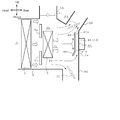
- FIG. 1 (a) is a side sectional view showing a configuration example on the downstream side of the heat exchanger of the vehicle air conditioner according to the present invention
- FIG. 1 (b) shows a portion of the air outlet opening of the air conditioner.
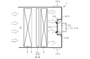
- FIG. 2 is a plan sectional view showing a configuration example on the downstream side of the heat exchanger of the vehicle air conditioner according to the present invention, and is a view seen from line AA of FIG. 1 (a).
- 3A and 3B are views showing the mounting state of the space image wall body and the function addition device, FIG. 3A is a side sectional view thereof, and FIG. 3B is a perspective view thereof.
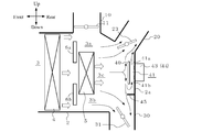
- FIG. 4 is a diagram illustrating the flow of air in the vent blowing mode.
- FIG. 4 is a diagram illustrating the flow of air in the vent blowing mode.
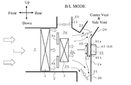
- FIG. 5 is a diagram illustrating the flow of air in the bi-level blowing mode.
- FIG. 6 is a diagram for explaining the flow of air in the spatial image wall body when the air with the added function is supplied to the vent outlet opening.
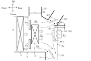
- FIG. 7 is a diagram illustrating the flow of air in the foot blowing mode.
- FIG. 8 is a diagram showing an example in which the spatial painting wall body is extended to the vent outlet.
- FIG. 9 is a diagram showing an example in which a portion of the spatial image wall body near the vent outlet opening is bent so as to follow the air flow of the vent outlet opening.
- FIG. 10 is a diagram showing an example in which the intermediate portion of the spatial painting wall body is projected to the upstream side.
- FIG. 11 is a diagram showing an example in which a guide wall is provided directly below the spatial painting wall body.
- FIG. 12 is a diagram showing an example in which the space painting wall body is bulged upstream so as to increase the passage area of the opening end near the foot blowing opening.
- 13A and 13B are views showing another example of the spatial painting wall body, in which FIG. 13A is a perspective view seen from above the front, FIG. 13B is a side sectional view, and FIG. 13C is a perspective view seen from diagonally above. Is.
- FIG. 14 is a diagram showing another example of the space image wall body, and is a perspective view showing three examples of communication portions communicating the function-added space and the air flow path.
- FIG. 14 is a diagram showing another example of the space image wall body, and is a perspective view showing three examples of communication portions communicating the function-added space and the air flow path.
- FIG. 15 is a diagram showing an example applied to an air conditioner in which a bypass passage is formed only on the upper side of the heater core.
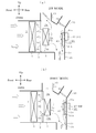
- 16A and 16B are diagrams showing a configuration example of supplying air to which ions are added to the foot blowout opening, where FIG. 16A shows a case of a differential foot blowout mode, and FIG. 16B shows a case of a foot blowout mode. It is a figure which shows.
- FIGS. 1 and 2 a center-mounted type vehicle air conditioner 1 (full center-mounted type or semi-center-mounted type air conditioner) mounted substantially in the center of the dashboard of the vehicle is shown.
- the air conditioner 1 is arranged on the vehicle interior side of the partition plate that separates the engine room and the vehicle interior, and the outside air (outside the vehicle interior air) and / or the inside air (vehicle) via an intake device (not shown). (Indoor air) is introduced into the air conditioning case 2.
- the air conditioning case 2 forms an air flow path 3 that flows toward the vehicle interior, and an evaporator 4 that forms a cooling heat exchanger that can cool the introduced air on the upstream side of the air flow path 3. Is arranged, and a heater core 5 forming a heat exchanger for heating is arranged on the downstream side of the evaporator 4.
- the evaporator 4 constitutes a part of the refrigeration cycle, and is erected in the air flow path 3 so that all the air introduced into the air conditioning case 2 can pass through, and cools the passing air as needed. It is possible.
- the heater core 5 heats the passing air using the cooling water of the engine as a heat source.
- the heater core 5 is erected so as to form a gap between the upper surface and the lower surface of the air conditioning case 2. Therefore, in the air flow path 3, an upper bypass passage 3a for bypassing the air that has passed through the evaporator 4 without passing through the heater core 5 is formed above the heater core 5, and the evaporator is formed below the heater core 5.
- a lower bypass passage 3b is formed to bypass the air that has passed through 4 without passing through the heater core 5.
- the bypass passages 3a and 3b are recessed by adjusting the installation height of the heater core 5 in the air conditioning case 2 or by denting the upper surface and the lower surface of the air conditioning case 2 facing the heater core 5 in a direction away from the heater core 5. May be formed by.
- the ratio of the air passing through the bypass passages 3a and 3b to the air passing through the heater core 5 is adjusted by the air mix doors 6a and 6b provided on the upstream side of the heater core 5.
- the opening degree of the upper bypass passage 3a is adjusted by the upper air mix door 6a that can slide along the end face of the heater core 5, and the opening degree of the lower bypass passage 3b slides along the end face of the heater core 5. It is designed to be adjusted by a possible lower air mix door 6b.
- a temperature control means for controlling the temperature of the air introduced into the air conditioning case 2 is formed by the evaporator 4, the heater core 5, the upper air mix door 6a, and the lower air mix door 6b.
- each bypass passage (upper bypass passage 3a, lower bypass passage 3b), and a mixing area 3c capable of mixing air that has passed through the heater core 5 are formed, and this mixing area is formed.
- the air-conditioning case 2 facing 3c is formed with a plurality of outlet openings for supplying air sent out toward the vehicle interior.
- a defrost outlet opening 10 for supplying air sent out toward the windshield of the vehicle is formed on the upper front side facing the mixing area 3c of the air conditioning case 2, and the upper rear side facing the mixing area 3c of the air conditioning case 2. Is formed with a vent outlet opening 20 for supplying air to be sent upward in the vehicle interior. Further, in the lower part of the air conditioning case 2 facing the mixing area 3c, a foot outlet opening 30 for supplying air to be sent downward to the vehicle interior is formed. Therefore, the air that has passed through the heat exchangers (evaporator 4, heater core 5) collides between the vent outlet 20 and the foot outlet 30 of the air conditioning case 2 to change the flow direction upward and downward.
- a wall portion 2a on the passenger compartment side is formed.
- vent outlet 20 is provided for each of the driver's seat and the passenger seat, and the center vent outlet 21 (center vent for the driver's seat) is located closer to the center in the lateral width direction (vehicle width direction).
- Blow-out opening 21a, center vent blow-out opening 21b for passenger seat) are provided, adjacent to the center vent blow-out opening 21 and side-vent blow-out opening 22 (driving) in the lateral width direction (vehicle width direction).
- the seat side vent outlet 22a and the passenger seat side vent outlet 22b) are provided.
- the foot outlet opening 30 is provided with the driver's seat foot outlet opening 30a at the lower part of the driver's seat side surface of the air conditioning case 2, and the passenger seat's foot outlet 30a is provided at the lower part of the passenger seat side surface of the air conditioning case 2.
- a foot outlet opening 30b is provided.
- the air that has passed through the heat exchangers may be guided to the outlet as it is, but the flow direction changes after colliding with the wall portion 2a on the passenger compartment side of the air conditioning case 2. If the upper air outlet is open, more air will flow toward the upper air outlet, and if the lower air outlet opening is open, the air will flow more toward the upper air outlet. More flow down.
- the opening degree of the defrost blowout opening 10 is adjusted by the defrost door 11 provided in the defrost blowout opening, and the vent blowout opening 20 (the opening degree of the center vent blowout opening 21 and the side vent blowout opening).
- the opening degree of the portion 22) is adjusted by the vent door 23 provided so as to face the center vent outlet opening 21 and the side vent outlet 22.
- the opening degree of the foot outlet opening 30 is adjusted by a foot door 31 provided so as to face the foot outlet opening 30.
- the opening degree of the side vent blowout opening 22 is adjusted so that the amount of air blown is always secured regardless of the blowout mode.
- a wall portion of an air conditioner case 2 that changes the flow direction of air that has passed through heat exchange evaporator 4, heater core 5
- evaporator 4, heater core 5 in this example, a vent outlet opening 20 and a foot outlet opening.
- a spatial air-conditioning wall body 40 is provided on the wall portion 2a on the vehicle interior side in the area between the 30 and the vehicle interior.
- the space painting wall body 40 is a rectangular front wall 40a facing the wall portion 2a of the air conditioning case 2 at a predetermined distance, and the front wall 40a. It is formed so as to include a side wall 40b extending from both side edges to the wall portion 2a of the air conditioning case 2, and has a shape in which the upper end portion and the lower end portion are open.
- a space (function addition space 41) covered by the space painting wall body is defined between the wall portion 2a of the air conditioning case 2 and the space painting wall body 40, and the function addition space 41 is defined as.
- a portion near the foot outlet opening that communicates with the air flow path 3 (mixing area 3c) via a first communication portion 41a that is provided near the vent outlet and opens toward the vent outlet 20. It communicates with the air flow path 3 (mixing area 3c) through the second communication portion 41b formed in.
- the first communication portion 41a and the second communication portion 41b are gaps formed between the space painting wall body 40 and the wall portion 2a, and in this example, the first communication portion to the second communication portion 2a.
- the cross-sectional area is equalized over the communication part.
- the wall portion 2a of the air-conditioning case 2 covered with the space painting wall body 40 is provided with a function addition device 43 that adds a predetermined function to the air passing through the function addition space 41. ..
- the function addition device 43 is configured as an ion generator 44 that adds ions to the air passing through the function addition space 41, and is attached to the outside of the wall portion 2a of the air conditioning case 2, and the wall portion 2a is attached.
- first communication portion 41a and the second communication portion 41b are formed symmetrically vertically with respect to the ion generator 44, and the space image wall 40 is on the vehicle interior side. It is installed at a position closer to the vent outlet 20 than the foot outlet 30 in the wall 2a.
- the air mix doors 6a and 6b are set to the full cool position (the position where all the air passing through the evaporator 4 is bypassed by the heater core 5 and passed through the bypass passages 3a and 3b).
- the vent blowing mode in which only the vent blowing opening 20 is opened, the air supplied from the upstream side of the heat exchangers 4 and 5 in the air conditioning case 2 passes through the evaporator 4 and then becomes the upper bypass passage 3a. It reaches the mixing area 3c through the lower bypass passage 3b and is guided to the vent outlet 20 through the mixing area 3c.
- the air guided from the mixing area 3c to the vent outlet 20 collides with the front wall of the space painting wall 40 and the walls of the air conditioning case on both sides of the space painting wall 40, and the flow direction is changed upward. It is guided to the vent outlet 20 along the surface of the space painting wall 40 and the wall 2a of the air conditioning case 2, and enters the function addition space 41 from the second communication portion 41b, and is generated by the ion generator 44. After the ions are added, they flow out from the first communication portion 41a to the air flow path 3 (mixing area 3c) and are guided to the vent outlet opening 20.
- the static pressure of the first communication portion 41a of the function addition space 41 is changed to the second communication due to the inspiration effect generated by the air flow guided to the vent outlet opening 20 along the surface of the space painting wall body. Since the pressure is lower than the static pressure of the portion 41b, the air in the function addition space 41 is towed (sucked) to the vent outlet opening 20 via the first communication portion 41a, and is also pulled (sucked) to the vent outlet 20 through the second communication portion 41b. The air in the mixing area 3c is sucked into the function addition space 41. Therefore, the flow of air in the function-added space 41 is promoted, and the air to which ions are added can be positively supplied to the vent outlet 20 without stagnation in this space.
- the air mix doors 6a and 6b are set at intermediate positions (positions where the air passing through the evaporator 4 is passed through the heater core 5 and the bypass passages (upper bypass passage 3a and lower bypass passage 3b)), and the vent outlet opening is set.
- the supplied air in the air conditioning case 2 passes through the evaporator 4 and then passes through the upper bypass passage 3a and the lower side. It is divided into air that passes through the bypass passage 3b and air that passes through the heater core 5, and merges behind the heater core 5 and collides with the wall portion 2a of the air conditioning case 2 and the front wall 40a of the space painting wall 40 in the flow direction. Is changed.
- part of the air that collided with the front wall 40a of the space painting wall 40 flows upward toward the vent outlet opening 20 in the flow direction, and the rest is directed downward to the foot.
- the first communication portion 41a is moved from the second communication portion 41b due to the air flow flowing through the mixing area 3c toward the vent blowout opening 20 as shown in FIG.
- an aspiration effect that pulls the air in the function addition space 41 is generated in the first communication portion 41a, and one of the air flowing toward the foot outlet opening in front of the space painting wall 40.
- the portion is sucked from the second communication portion 41b into the function addition space 41, where ions are added from the ion generator 44 and then discharged from the first communication portion 41a to the vent outlet opening 20. Therefore, the air does not stagnate in the function addition space 41, and it is possible to sufficiently supply the air to which the ions are added to the vent outlet opening 20.
- the air mix doors 6a and 6b are set to full hot positions (positions where the air that has passed through the evaporator 4 passes only the heater core 5), the defrost outlet opening 10 is closed, the center vent outlet opening 21 is closed, and the side vent outlet is blown out.
- the air supplied into the air conditioning case 2 passes through the evaporator 4 and then the heater core 5.
- the flow direction is changed by colliding with the wall portion 2a on the vehicle interior side of the air conditioning case 2 and the front wall 40a of the space painting wall body 40.
- a part of the air that collides with the front wall 40a of the space painting wall 40 is directed upward in the flow direction and flows toward the side vent outlet opening 22, and the rest is directed downward. It flows toward the foot outlet opening 30.
- the space painting wall 40 is arranged closer to the vent outlet 20 than the foot outlet 30, the first communication portion 41a is caused by the air flow toward the side vent outlet 22.
- the ions are sucked into the air, and after the ions are added from the ion generator 44, they are discharged from the first communication portion 41a to the side vent outlet opening 22. Therefore, even in the foot blowing mode in which the side vent blowing opening 22 is opened, it is possible to sufficiently supply the air to which the ions are added to the side vent blowing opening 22.
- FIGS. 8 to 8 to FIG. 12 The modification shown in No. 12 may be adopted.
- the distance between the first communication portion 41a and the vent outlet opening 20 is made shorter than the distance between the second communication portion and the foot outlet opening, and the first communication portion is formed. Is directly opened to the vent outlet to supply the air added by the ions directly to the vent outlet.
- the first communication portion directly communicates with the vent outlet opening, it becomes easy to obtain an inspiration effect, and the air to which ions are added in the function addition space 41 is vented more effectively. It becomes possible to supply to the blowout opening 20.
- the upper end portion of the space painting wall body 40 is provided so that the first communication portion 41a enters the vent outlet opening 20. May be extended toward the opening end along the inner wall surface of the vent outlet opening 20.
- the space painting wall body 40 may be configured so that the intermediate portion of the front wall 40a where the air flowing from the upstream collides protrudes to the upstream side (mixing area 3c). ..
- the air flowing from the upstream is smoothly divided into the upper side and the lower side by the front wall 40a of the space painting wall 40, so that the area where the air stays in front of the space painting wall 40 is defined.
- a plate-shaped guide portion 45 projecting inward from the wall portion 2a of the air conditioning case 2 is provided below the second communication portion 41b of the spatial image wall body 40, and is more than the guide portion 45.
- the air flowing from the upper side to the lower side is received and easily guided to the second communication portion 41b.
- the second communication portion 41b is used as an aspi.
- the inconvenience of generating the ration effect can be eliminated, and the aspiration effect generated in the first communication portion 41a makes it possible to promote the suction of air into the function-added space 41.
- the means for facilitating the introduction of air into the function-added space 41 may be provided in the space painting wall body 40.
- the lower end of the space painting wall 40 may be bulged toward the mixing area 3c to form the guide portion 40c, so that the air flow entering the function-added space 41 may be easily formed.
- the above-mentioned space image wall 40 shows an example in which the cross-sectional areas of the flow paths are substantially equal from the first communication portion 41a to the second communication portion 41b for communicating the function addition space 41 with the air flow path 3.
- the cross-sectional area of the flow path may be narrowed (the cross-sectional area of the flow path is smaller than that of the communication portion) in the intermediate portion.
- the function-added space 41 has a semicircular cross section
- the middle portion of the space painting wall 40 has a shape in which the middle portion is gently recessed so that the cross-sectional area of the flow path is the smallest. ..
- the lower portion of the space painting wall 40 is divided into two parts, and the first communication portion 41a is opened in the vicinity of the vent outlet 20 and toward the vent outlet 20.
- the driver's seat foot blow-out opening 30a and the passenger seat foot blow-out opening 30b may be provided with second and third communication portions 41b and 41c, respectively.
- the driver's seat foot outlet opening 30a is formed on the driver's seat side surface of the air conditioner case 2
- the passenger seat foot outlet opening 30b is formed on the passenger seat side surface of the air conditioner case 2. It is effective for such air conditioners.
- the upper bypass passage 3a is formed on the upper side of the heater core 5, and the lower bypass passage 3b is formed on the lower side of the heater core 5, and the opening degrees of the respective bypass passages 3a and 3b are set to separate air.
- the bypass passage 3d is formed only above the heater core 5, and the air passing through the bypass passage 3d and the air bypassing the heater core 5 are bypassed.
- the same effect can be obtained by adopting the same configuration.
- the second communication portion 41b of the space painting wall body 40 is made lower than the first communication portion 41a.
- the space painting wall body 40 is extended so that the second communication portion 41a that opens toward the foot outlet opening 30 is close to the foot outlet opening. , It is preferable to increase the inspiration effect at the second communication portion 41b.
- a guide plate may be provided directly above the first communication portion 41a, or the intermediate portion of the front wall 40a may be projected upstream so as to increase the amount of air diverted to the foot outlet opening in front of the space painting wall body 40.
- the upper end of the space painting wall 40 may be bulged toward the mixing area 3c.
- the function addition device 43 (ion generator 44) is attached to the outer surface of the wall portion 2a of the air conditioning case 2, but the function addition device 43 is the wall portion 2a of the air conditioning case 2. It may be attached to the inner surface or may be attached to the space painting wall body 40. Further, in the above example, the ion generator 44 is given as an example of the function addition device for adding the function to the air passing through the function addition space, but the fragrance generator for adding the fragrance function and the deodorization for adding the deodorization function are given. Any of the device, the humidity requesting device for adding the humidity adjusting function, the sterilizing device for adding the sterilizing function, or each of the above-mentioned devices may be provided in combination as appropriate.
- Air conditioner for vehicles Air conditioner case 2a Wall part 3 Air flow path 4 Evaporator 5 Heater core 6a, 6b, 6c Mix door 20 Vent outlet opening 30 Foot outlet opening 40 Space image wall body 41 Function additional space 41a First Communication section 41b Second communication section 43 Function addition device 44 Ion generator
Landscapes
- Engineering & Computer Science (AREA)
- Mechanical Engineering (AREA)
- Physics & Mathematics (AREA)
- Thermal Sciences (AREA)
- Air-Conditioning For Vehicles (AREA)
Abstract
空気の流方向を変更する壁部のどの部分に機能付加装置を設置する場合でも、機能を付加した空気を十分に車室内に供給することが可能な車両用空調装置を提供する。 【解決手段】内部に空気流路(3)が形成され、複数の吹出開口部(10,20,30)を備えた空調ケース(2)の壁部であって、熱交換器(4,5)を通過した空気の流方向を変更させる壁部(2a)に、該壁部(2a)との間に機能付加空間(41)を画成する空間画成壁体(40)を設け、また壁部(2a)に機能付加空間(41)を通過する空気に対して所定の機能を付加する機能付加装置(43)を設ける。機能付加空間(41)は、少なくとも2つの連通部(41a、41b)を介して空気流路(3)に連通し、少なくとも1つの連通部(41a)を、所定の吹出モードで他の連通部(41b)よりも低圧となるようにいずれかの吹出開口部(ベント吹出開口部20)に向けて開口させる。
Description
本発明は、イオンや芳香などの機能を付加した空気を車室内に十分に供給することが可能な車両用空調装置に関する。
例えば、特許文献1においては、降車時の乗員の帯電を緩和または除電するために、空調空気の送風経路にイオン発生装置を配置し、乗員の降車意思が検出された場合に、空調装置の吹出口を乗員に対して送風する吹出口に設定し、ファンによる送風を行うと共に、イオン発生装置から送風経路内にイオンを発生させるようにした車両用空調装置が開示されている。
特にこの例では、空調装置のヒータコアとベントダクトとの間の送風経路、より具体的には、空調装置の空調ケースのエバポレータの下流側であって、デフダクトが接続する部位より上流側に、空調空気にイオンを供給するイオン発生器を設置し、乗員の降車意思が検出された場合に、ベント吹出口からの送風に切り替えると共にイオン発生器を作動させて、エバポレータに付着している凝縮水によって加湿された空気にイオン発生器からイオンを付加させ、このイオンが付加された空気をベント吹出口から車室へ供給するようにしている。
また、特許文献2には、イオンが付加された空気を車室内に吹き出す車両用空調装置において、熱交換器を通過した空気を衝突させて流れを上方に向かわせるための衝突側の壁面、又は、この壁面の横隣りに連なる側方側の壁面の所定位置にイオン発生器を配置する構成が開示されている。特に、同文献の図7で示される構成においては、空調ケースの熱交換器の下流側となり、熱交換器を通過した空気を衝突させて上方に向かわせるための後方壁面のうち、ヒータコアが対向する範囲よりもベント吹出開口部寄りの範囲にイオン発生器を取り付け、ヒータコアを通過して後方壁面に衝突した後に上方へ向かう空気にイオンを付加させ、イオン発生器で発生したイオンが後方壁面に衝突して消滅することを回避するようにしている。
しかしながら、前者の構成をエバポレータ及びヒータコアを車両前後方向に配置したセンター置きタイプの空調装置(フルセンター置きタイプやセミセンター置きタイプの空調装置)に適用する場合には、空調装置のエバポレータとデフダクトとの間にイオン発生器を設置する空間的余裕は殆どなく、また、熱交換器を通過した空気は、熱交換器の下流側で空調ケースに衝突して大きく流方向が変更された後に各吹出開口部へ送られるので、イオン発生器で発生したイオンが空調ケースの壁面に衝突して消滅しやすくなる。このため、イオン発生器の設置位置や設置構造の見直しが必要となる。
この点、後者の構成においては、熱交換器を通過した空気を衝突させる後方壁面のうち、ヒータコアが対向する範囲よりもベント開口部寄りの範囲にイオン発生器を取り付けるので、機能付加装置の設置スペースを確保しやすくなると共に、イオン発生器で発生した空気が空調ケースの壁面に衝突して消滅する不都合を低減できるが、車両のダッシュボード内に設置される空調装置の設置スペースは、他の部品や機器などに割り当てられるスペース等との関係で、かなり制限的なものとなり、熱交換器を通過した空気を衝突させる後方壁面と謂えども、吹出口寄りの部分に十分な設置スペースを確保することができない場合がある。したがって、このような場合には、イオン発生器の設置位置を変更せざるを得ず、例えば、熱交換器を通過した空気を衝突させる壁面であって、空気の流方向が上下に分かれる部位(ベント吹出開口部へ向けられる空気とフット吹出開口部へ向けられる空気とに分岐する部位)にイオン発生器を設置せざるを得ない場合も出てくる。
このような上下に空気が分かれる壁面部位は、その部分で空気の淀みが発生しやすくなり、その部分にイオン発生器が設置されると、イオンを付加させた空気を効果的に吹出開口部へ供給することができなくなる不都合が考えられる。
本発明は、係る事情に鑑みてなされたものであり、空気の流方向を変更する壁部のどの部分に機能付加装置を設置する場合でも、機能を付加した空気を十分に車室内に供給することが可能な車両用空調装置を提供することを主たる課題としている。
上記課題を達成するために、本発明にかかる車両用空調装置は、機能が付加された空気を車室内に放出する車両用空調装置であって、
内部に空気流路が形成され、導入された空気を車室内に吹き出すことが可能な複数の吹出開口部を備えた空調ケースと、
前記空調ケース内に配置され、導入された空気を熱交換させる熱交換器と、を備え、
前記空調ケースの壁部であって前記熱交換器を通過した空気の流方向を変更させる壁部に、該壁部との間に機能付加空間を画成する空間画成壁体を設け、
前記壁部又は前記空間画成壁体に、前記機能付加空間を通過する空気に対して所定の機能を付加する機能付加装置を設け、
前記機能付加空間は、少なくとも2つの連通部を介して前記空気流路に連通し、少なくとも1つの連通部は、所定の吹出モードで他の連通部よりも低圧となるように前記複数の吹出開口部のうちのいずれかに向けて開口していることを特徴としている。
ここで、連通部は、空間画成壁体に形成された開口部によって形成されるものであっても、空間画成壁体と壁部との間に形成されるものであってもよい。
したがって、熱交換器を通過した空気の流方向を変更させる空調ケースの壁部に空間画成壁体を設けて機能付加空間を画成し、空調ケースの熱交換器を通過した空気の流方向を変更させる壁部又は空間画成壁体に機能付加装置を設けて機能付加空間を通過する空気に対して所定の機能を付加し、機能付加空間と空気流路とを連通する空間画成壁体の少なくとも1つの連通部を所定の吹出モードで他の連通部よりも低圧となるようにいずれかの吹出開口部に向けて開口したので、所定の吹出モードにおいて、機能付加空間には、他の連通部から空気が吸引され、機能付加空間で機能付加装置から機能が付加された後に、相対的に低圧となる連通部から空気流路に戻される(少なくとも1つの連通部に機能付加空間を通過した空気を牽引する効果を持たせることが可能となる)。このため、機能付加装置によって機能が付加された空気を、機能付加空間に停留させることなく開口している吹出開口部から効果的に供給することが可能となる。
以上の構成において、複数の吹出開口部を、車室上方へ吹き出す空気を供給するベント吹出開口部と、車室下方へ吹き出す空気を供給するフット吹出開口部とし、特にベント吹出開口部から機能を付加した空気を十分に供給したい場合には、前記機能付加装置と前記空間画成壁体を、前記ベント吹出開口部と前記フット吹出開口部との間の前記壁部に設け、前記機能付加空間を、前記ベント吹出開口部寄りに設けられた第1の連通部と、前記フット吹出開口部寄りに設けられた第2の連通部と、を介して前記空気流路に連通し、前記第1の連通部を、前記ベント吹出開口部が開となる吹出モード時に前記第2の連通部よりも低圧となるように前記ベント吹出開口部に向けて開口するとよい。
このような構成においては、空間画成壁体を、ベント吹出開口部とフット吹出開口部との間の壁部に設け、ベント吹出開口部寄りに設けられた第1の連通部を、ベント吹出開口部が開となる吹出モード時(ベント吹出モード時又はバイレベル吹出モード時)にフット吹出開口部寄りに設けられた第2の連通部よりも低圧となるようにベント吹出開口部に向けて開口したので、機能付加空間には、第2の連通部から空気が吸引され、機能付加空間で機能付加装置から機能が付加された後に、相対的に低圧となる第1の連通部から空気流路に戻される(第1の連通部に機能付加空間内の空気を牽引する効果を持たせることが可能となる)。このため、機能付加空間に第2の連通部を介して空気を積極的に吸引することができると共に機能が付加された空気を機能付加空間に停留させずに第1の連通部からベント吹出開口部へ効果的に導くことが可能となる。
また、複数の吹出開口部を、車室上方へ吹き出す空気を供給するベント吹出開口部と、車室下方へ吹き出す空気を供給するフット吹出開口部とし、特にフット吹出開口部から機能を付加した空気を十分に供給したい場合には、前記機能付加装置と前記空間画成壁体を、前記ベント吹出開口部と前記フット吹出開口部との間の前記壁部に設け、機能付加空間を、前記ベント吹出開口部寄りに設けられた第1の連通部と、前記フット吹出開口部寄りに設けられた第2の連通部と、を介して前記空気流路に連通し、前記第2の連通部を、前記フット吹出開口部が開となる吹出モード時に前記第1の連通部よりも低圧となるように前記フット吹出開口部に向けて開口するとよい。
このような構成においては、空間画成壁体を、ベント吹出開口部とフット吹出開口部との間の壁部に設け、フット吹出開口部寄りに設けられた第2の連通部を、フット吹出開口部が開となる吹出モード時(フット吹出モード時)にベント吹出開口部寄りに設けられた第1の連通部よりも低圧となるようにフット吹出開口部に向けて開口したので、機能付加空間には、第1の連通部から空気が吸引され、機能付加空間で機能付加装置から機能が付加された後に、相対的に低圧となる第2の連通部から空気流路に戻される(第2の連通部に機能付加空間内の空気を牽引する効果を持たせることが可能となる)。このため、機能付加空間に第1の連通部を介して空気を積極的に吸引することができると共に機能が付加された空気を機能付加空間に停留させずに第2の連通部からフット吹出開口部へ効果的に導くことが可能となる。
ここで、相対的に低圧となる連通部は、前記他の連通部よりも吹出開口部の近い位置に形成されるとよい。
このように、空間画成壁体の相対的に低圧となる連通部の開口端を他の連通部よりも吹出開口部により近づけることで、機能付加空間内の空気の牽引効果を大きくすることが可能となる。
このように、空間画成壁体の相対的に低圧となる連通部の開口端を他の連通部よりも吹出開口部により近づけることで、機能付加空間内の空気の牽引効果を大きくすることが可能となる。
また、前記空間画成壁体(13)は、上流から流れる空気が衝突する面の中間部を、上流側へ突出させるようにしてもよい。
このような構成においては、空間画成壁体の上流から流れる空気が衝突する面で空気をスムーズに連通部に向かって分流させることが可能となり、機能付与空間の空気の牽引効果を得やすいものとなる。
このような構成においては、空間画成壁体の上流から流れる空気が衝突する面で空気をスムーズに連通部に向かって分流させることが可能となり、機能付与空間の空気の牽引効果を得やすいものとなる。
さらに、前記空間画成壁体の前記他の連通部が形成される部分又はその近傍には、空気を前記他の連通部へ導入しやすくするガイド部を設けるようにしてもよい。
このようなガイド部としては、他の連通部の通路断面積を開口端に向かって大きくするように空間画成壁体をチャンバ内に膨出させたり、他の連通部の近傍に機能付加空間から遠ざかろうとする空気をブロックするガイド板を設けたりするようにしてもよい。
このようなガイド部としては、他の連通部の通路断面積を開口端に向かって大きくするように空間画成壁体をチャンバ内に膨出させたり、他の連通部の近傍に機能付加空間から遠ざかろうとする空気をブロックするガイド板を設けたりするようにしてもよい。
さらにまた、前記空間画成壁体によって画成される前記機能付加空間は、中間部の通路断面積を前記連通部の通路断面積よりも小さく形成してもよい。
このような構成においては、機能付加空間に吸引された空気は、機能付加装置から機能が付加されると共に中間部で流速が早められ、その後、通路断面積が相対的に大きくなっている連通部から放出されるので、機能が付加された空気が空間画成壁体に衝突することなく吹出開口部へ速やかに供給される。このため、機能が付加された空気が空間画成壁体に衝突して機能を低減する不都合を回避することが可能となる。
このような構成においては、機能付加空間に吸引された空気は、機能付加装置から機能が付加されると共に中間部で流速が早められ、その後、通路断面積が相対的に大きくなっている連通部から放出されるので、機能が付加された空気が空間画成壁体に衝突することなく吹出開口部へ速やかに供給される。このため、機能が付加された空気が空間画成壁体に衝突して機能を低減する不都合を回避することが可能となる。
以上の車両用空調装置としては、前記熱交換器として、通過する空気を冷却する冷却用熱交換器と、この冷却用熱交換器の下流側に配置され、通過する空気を加熱する加熱用熱交換器と、を有する場合に、前記加熱用熱交換器を、該加熱用熱交換器の上側及び下側にバイパス通路を形成するように前記空気流路に配置するものであっても、該加熱用熱交換器の上側のみにバイパス通路を形成するように前記空気流路に配置するものであってもよい。
なお、前記機能付加装置により空気に付加する機能としては、イオン付加機能、芳香機能、脱臭機能、湿度調整機能、除菌機能の少なくとも1つを有するものが考えられる。
以上述べたように、本発明によれば、熱交換器を通過した空気の流方向を変更させる空調ケースの壁部に空間画成壁体を設けて機能付加空間を画成し、空調ケースの壁部又は空間画成壁体に機能付加空間を通過する空気に対して所定の機能を付加する機能付加装置を設け、機能付加空間と空気流路とを連通する少なくとも1つの連通部を、所定の吹出モードで他の連通部よりも低圧となるようにいずれかの吹出開口部に向けて開口したので、少なくとも1つの連通部に機能付加空間を通過した空気を牽引する効果を持たせることが可能となり、機能付加装置によって機能が付加された空気を、機能付加空間に停留させることなく開口している吹出開口部へ十分に供給することが可能となる。
以下、この発明の実施の形態を図面により説明する。
図1及び図2において、車両のダッシュボード内の略中央に搭載されるセンター置きタイプの車両用空調装置1(フルセンター置きタイプやセミセンター置きタイプの空調装置)が示されている。この空調装置1は、エンジンルームと車室とを区画する仕切板よりも車室側に配置されているもので、図示しないインテーク装置を介して、外気(車室外空気)および/または内気(車室内空気)を空調ケース2内に導入するようにしている。
図1及び図2において、車両のダッシュボード内の略中央に搭載されるセンター置きタイプの車両用空調装置1(フルセンター置きタイプやセミセンター置きタイプの空調装置)が示されている。この空調装置1は、エンジンルームと車室とを区画する仕切板よりも車室側に配置されているもので、図示しないインテーク装置を介して、外気(車室外空気)および/または内気(車室内空気)を空調ケース2内に導入するようにしている。
空調ケース2は、車室へ向かって流れる空気流路3を形成するもので、この空気流路3の上流側には、導入された空気を冷却可能とする冷却用熱交換器をなすエバポレータ4が配置され、このエバポレータ4の下流側には加熱用熱交換器をなすヒータコア5が配置されている。
エバポレータ4は、冷凍サイクルの一部を構成するもので、空調ケース2内に導入された全ての空気が通過するように空気流路3内に立設され、必要に応じて通過する空気を冷却可能としている。
ヒータコア5は、エンジンの冷却水を熱源として通過空気を加熱するもので、この例では、空調ケース2の上面および下面との間に間隙が形成されるように立設されている。したがって、空気流路3には、ヒータコア5よりも上側に、エバポレータ4を通過した空気をヒータコア5を通過させずにバイパスさせる上側バイパス通路3aが形成され、また、ヒータコア5の下側に、エバポレータ4を通過した空気をヒータコア5を通過させずにバイパスさせる下側バイパス通路3bが形成されている。
なお、バイパス通路3a,3bは、ヒータコア5の空調ケース2内の設置高さを調節することによって、又は、ヒータコア5と対峙する空調ケース2の上面や下面をヒータコア5から遠ざける方向に窪ませることによって形成してもよい。
それぞれのバイパス通路3a,3bを通過する空気と、ヒータコア5を通過する空気との割合は、ヒータコア5の上流側に設けられたエアミックスドア6a,6bによって調整されるようになっている。この例では、上側バイパス通路3aの開度は、ヒータコア5の端面に沿ってスライド可能な上側エアミックスドア6aによって調節され、下側バイパス通路3bの開度は、ヒータコア5の端面に沿ってスライド可能な下側エアミックスドア6bによって調節されるようになっている。
これらエバポレータ4、ヒータコア5、上側エアミックスドア6a及び下側エアミックスドア6bによって空調ケース2内に導入された空気の温度を調節する温度調節手段が形成されている。
これらエバポレータ4、ヒータコア5、上側エアミックスドア6a及び下側エアミックスドア6bによって空調ケース2内に導入された空気の温度を調節する温度調節手段が形成されている。
エバポレータ4の下流側には、ヒータコア5、それぞれのバイパス通路(上側バイパス通路3a、下側バイパス通路3b)、およびヒータコア5を通過した空気を混合可能とする混合エリア3cが形成され、この混合エリア3cに臨む空調ケース2には、車室に向かって送出される空気を供給する複数の吹出開口部が形成されている。
空調ケース2の混合エリア3cに臨む上部前方側には、車両のフロントガラスに向けて送出される空気を供給するデフロスト吹出開口部10が形成され、空調ケース2の混合エリア3cに臨む上部後方側には、車室上方へ向けて送出される空気を供給するベント吹出開口部20が形成されている。また、空調ケース2の混合エリア3cに臨む下部には、車室下方に向けて送出される空気を供給するフット吹出開口部30が形成されている。
したがって、空調ケース2のベント吹出開口部20とフット吹出開口部30との間には、熱交換器(エバポレータ4、ヒータコア5)を通過した空気が衝突して流方向を上方及び下方へ変更する車室側の壁部2aが形成されている。
したがって、空調ケース2のベント吹出開口部20とフット吹出開口部30との間には、熱交換器(エバポレータ4、ヒータコア5)を通過した空気が衝突して流方向を上方及び下方へ変更する車室側の壁部2aが形成されている。
ここで、ベント吹出開口部20は、運転席用と助手席用のそれぞれに設けられているもので、横幅方向(車幅方向)の中央寄りにセンタベント吹出開口部21(運転席用センタベント吹出開口部21a、助手席用センタベント吹出開口部21b)が設けられ、このセンタベント吹出開口部21に隣接し、横幅方向(車幅方向)の側方寄りにサイドベント吹出開口部22(運転席用サイドベント吹出開口部22a、助手席用サイドベント吹出開口部22b)が設けられている。
また、この例において、フット吹出開口部30は,空調ケース2の運転席用側面の下部に運転席用フット吹出開口部30aが設けられ、空調ケース2の助手席用側面の下部に助手席用フット吹出開口部30bが設けられている。
また、この例において、フット吹出開口部30は,空調ケース2の運転席用側面の下部に運転席用フット吹出開口部30aが設けられ、空調ケース2の助手席用側面の下部に助手席用フット吹出開口部30bが設けられている。
したがって、熱交換器(エバポレータ4、ヒータコア5)を通過した空気は、そのまま吹出開口部へ導かれるものもあるが、空調ケース2の車室側の壁部2aに衝突した後に、流方向が変更され、上側へ向かう空気と下側へ向かう空気とに分けられ、上側の吹出開口部が開いていれば、その開口部に向かってより多く流れ、下側の吹出開口部が開いていれば、下側に向かってより多く流れる。
なお、デフロスト吹出開口部10の開度は、このデフロスト吹出開口部内に設けられたデフロストドア11によって調節され、ベント吹出開口部20(センタベント吹出開口部21の開度、及び、サイドベント吹出開口部22)の開度は、センタベント吹出開口部21及びサイドベント吹出開口部22に臨むように設けられたベントドア23によって調節される。また、フット吹出開口部30の開度は、このフット吹出開口部30に臨むように設けられたフットドア31によって調節される。ここで、この例においては、サイドベント吹出開口部22は、吹出モードに拘わらず、常時送風量が確保されるように開度が調節されるようになっている。
このような車両用空調装置1において、熱交換(エバポレータ4、ヒータコア5)を通過した空気の流方向を変更させる空調ケース2の壁部、この例では、ベント吹出開口部20とフット吹出開口部30との間の領域の車室側の壁部2aには、空間画成壁体40が設けられている。
この空間画成壁体40は、図3にも示されるように、空調ケース2の壁部2aとの間に所定の間隔をあけて対峙する矩形状の正面壁40aと、この正面壁40aの両側縁から空調ケース2の壁部2aにかけて延設された側壁40bとを備えるように形成されており、上端部と下端部が開放された形状となっている。
この空間画成壁体40は、図3にも示されるように、空調ケース2の壁部2aとの間に所定の間隔をあけて対峙する矩形状の正面壁40aと、この正面壁40aの両側縁から空調ケース2の壁部2aにかけて延設された側壁40bとを備えるように形成されており、上端部と下端部が開放された形状となっている。
したがって、空調ケース2の壁部2aと空間画成壁体40との間には、空間画成壁体によって覆われた空間(機能付加空間41)が画成され、この機能付加空間41は、ベント吹出開口部寄りに設けられると共にベント吹出開口部20に向けて開口する第1の連通部41aを介して空気流路3(混合エリア3c)に連通し、また、フット吹出開口部寄りの部分に形成された第2の連通部41bを介して空気流路3(混合エリア3c)に連通している。これら第1の連通部41aと第2の連通部41bは、空間画成壁体40と壁部2aとの間に形成された間隙であり、この例では、第1の連通部から第2の連通部にかけて断面積を等しくしている。
そして、この空間画成壁体40で覆われた空調ケース2の壁部2aには、前記機能付加空間41を通過する空気に対して所定の機能を付加する機能付加装置43が設けられている。
この例では、機能付加装置43は、機能付加空間41を通過する空気に対してイオンを付加するイオン発生装置44として構成され、空調ケース2の壁部2aの外側に取り付けられ、この壁部2aに形成された通孔2bを介してイオンを発生させる陰極44a及び陽極44bを機能付加空間41に臨ませるようにしている。
この例では、機能付加装置43は、機能付加空間41を通過する空気に対してイオンを付加するイオン発生装置44として構成され、空調ケース2の壁部2aの外側に取り付けられ、この壁部2aに形成された通孔2bを介してイオンを発生させる陰極44a及び陽極44bを機能付加空間41に臨ませるようにしている。
また、この例では、第1の連通部41aと第2の連通部41bは、イオン発生装置44に対して上下に対称的に形成されており、空間画成壁体40は、車室側の壁部2aのうち、フット吹出開口部30よりもベント吹出開口部20寄りの位置に設置されている。
以上の構成において、図4に示されるように、エアミックスドア6a,6bをフルクール位置(エバポレータ4を通過した空気の全てをヒータコア5をバイパスさせてバイパス通路3a,3bを通過させる位置)とし、ベント吹出開口部20のみを開とするベント吹出モードにおいては、空調ケース2内の熱交換器4,5よりも上流側から供給された空気は、エバポレータ4を通過した後に上側バイパス通路3aと下側バイパス通路3bを通って混合エリア3cに至り、この混合エリア3cを介してベント吹出開口部20へ導かれる。
混合エリア3cからベント吹出開口部20へ導かれる空気は、空間画成壁体40の正面壁及び空間画成壁体の両側の空調ケースの壁部に衝突して流方向が上方に変更され、空間画成壁体40の表面及び空調ケース2の壁部2aに沿ってベント吹出開口部20へ導かれると共に、機能付加空間41に第2の連通部41bから入り、イオン発生装置44で発生されたイオンが付加された後に第1の連通部41aから空気流路3(混合エリア3c)に流出されてベント吹出開口部20へ導かれる。
この際、空間画成壁体の表面に沿ってベント吹出開口部20へ導かれる空気の流れによって生じるアスピレーション効果によって、機能付加空間41の第1連通部41aの静圧は、第2の連通部41bの静圧よりも低くなるので、機能付加空間41の空気は第1の連通部41aを介してベント吹出開口部20に牽引(吸引)されると共に、第2の連通部41bを介して混合エリア3cの空気が機能付加空間41に吸引される。このため、機能付加空間41での空気の流れが促進され、イオンが付加された空気をこの空間内に淀ませることなくベント吹出開口部20へ積極的に供給することが可能となる。
また、エアミックスドア6a,6bを中間位置(エバポレータ4を通過した空気をヒータコア5を通過させると共にバイパス通路(上側バイパス通路3a及び下側バイパス通路3b)を通過させる位置)とし、ベント吹出開口部20とフット吹出開口部30を開とするバイレベル吹出モードにおいては、図5に示されるように、空調ケース2内の供給された空気は、エバポレータ4を通過した後に上側バイパス通路3aと下側バイパス通路3bを通る空気とヒータコア5を通過する空気とに分けられ、ヒータコア5の後方で合流すると共に空調ケース2の壁部2aや空間画成壁体40の正面壁40aに衝突して流方向が変更される。
このうち、空間画成壁体40の正面壁40aに衝突した空気は、一部が流方向を上側に向けられてベント吹出開口部20に向かって流れ、また残りが下側に向けられてフット吹出開口部30に向かって流れるが、図6にも示されるように、混合エリア3cをベント吹出開口部20に向けて流れる空気流によって、第1の連通部41aは第2の連通部41bよりも相対的に低圧となり、第1の連通部41aに機能付加空間41の空気を牽引するアスピレーション効果が発生し、空間画成壁体40の手前でフット吹出開口部へ向かって流れる空気の一部が第2の連通部41bから機能付加空間41に吸引され、ここでイオン発生装置44からイオンが付加された後に第1の連通部41aからベント吹出開口部20へ放出される。このため、機能付加空間41内で空気が淀むことはなく、ベント吹出開口部20にイオンが付加された空気を十分に供給することが可能となる。
なお、エアミックスドア6a,6bをフルホット位置(エバポレータ4を通過した空気をヒータコア5のみを通過させる位置)とし、デフロスト吹出開口部10を閉、センタベント吹出開口部21を閉、サイドベント吹出開口部22とフット吹出開口部30を開とするフット吹出モードにおいては、図7に示されるように、空調ケース2内に供給された空気は、エバポレータ4を通過した後にヒータコア5を通過し、空調ケース2の車室側の壁部2aや空間画成壁体40の正面壁40aに衝突して流方向が変更される。
このうち、空間画成壁体40の正面壁40aに衝突した空気は、一部が流方向を上側に向けられてサイドベント吹出開口部22に向かって流れ、また残りが下側に向けられてフット吹出開口部30に向かって流れる。この際、空間画成壁体40はフット吹出開口部30よりもベント吹出開口部20に近づけて配置されているので、サイドベント吹出口22へ向かった流れる空気流によって、第1の連通部41aには機能付加空間41の空気をベント吹出開口部20側へ牽引するアスピレーション効果が発生し、フット吹出開口部30へ向かって流れる空気の一部が第2の連通部41bから機能付加空間41に吸引され、ここでイオン発生装置44からイオンが付加された後に第1の連通部41aからサイドベント吹出開口部22へ放出される。このため、サイドベント吹出開口部22を開とするフット吹出モードにおいても、サイドベント吹出開口部22にイオンが付加された空気を十分に供給することが可能となる。
以上においては、ベント吹出開口部20へイオンを付加した空気を供給する構成について説明したが、ベント吹出開口部20へより効果的にイオンを付加した空気を供給する方法としては、図8~図12に示す変形例を採用してもよい。
このうち、図8の例は、第1の連通部41aとベント吹出開口部20との距離を、第2の連通部とフット吹出開口部との距離よりも短くすると共に、第1の連通部をベント吹出開口部に直接開放することで、イオンが付加させた空気を直接ベント吹出開口部へ供給するようにしている。
このような構成においては、ベント吹出開口部に第1の連通部が直接連通するので、アスピレーション効果を得やすいものとなり、機能付加空間41内のイオンが付加された空気をより効果的にベント吹出開口部20に供給することが可能となる。
このような構成においては、アスピレーション効果をより高めるために、図9に示されるように、第1の連通部41aをベント吹出開口部20に入り込むように,空間画成壁体40の上端部をベント吹出開口部20の内壁面に沿って開口端に向けて延設させてもよい。
このような構成においては、ベント吹出開口部に第1の連通部が直接連通するので、アスピレーション効果を得やすいものとなり、機能付加空間41内のイオンが付加された空気をより効果的にベント吹出開口部20に供給することが可能となる。
このような構成においては、アスピレーション効果をより高めるために、図9に示されるように、第1の連通部41aをベント吹出開口部20に入り込むように,空間画成壁体40の上端部をベント吹出開口部20の内壁面に沿って開口端に向けて延設させてもよい。
また、空間画成壁体40は、図10に示されるように、上流から流れる空気が衝突する正面壁40aの中間部を、上流側(混合エリア3c)へ突出させるように構成してもよい。
このような構成においては、上流から流れてくる空気が空間画成壁体40の正面壁40aでスムーズに上側と下側へ分かれるので、空間画成壁体40の前面で空気が停留する領域を形成しにくくすると共に、空気を上下に方向付けて確実に流すことでアスピレーション効果を高めることが可能となる。
この場合においても、ベント吹出口側(第1の連通部41a側)でアスピレーション効果を得るためには、正面壁40aに衝突した空気の多くをデフロスト吹出開口部に向けて(上方に向けて)流れるように、空気を分岐させる位置を正面壁40aの下部寄りにするとよい。
このような構成においては、上流から流れてくる空気が空間画成壁体40の正面壁40aでスムーズに上側と下側へ分かれるので、空間画成壁体40の前面で空気が停留する領域を形成しにくくすると共に、空気を上下に方向付けて確実に流すことでアスピレーション効果を高めることが可能となる。
この場合においても、ベント吹出口側(第1の連通部41a側)でアスピレーション効果を得るためには、正面壁40aに衝突した空気の多くをデフロスト吹出開口部に向けて(上方に向けて)流れるように、空気を分岐させる位置を正面壁40aの下部寄りにするとよい。
図11の例では、空間画成壁体40の第2の連通部41bの下方に空調ケース2の壁部2aから内側に突設した板状のガイド部45を設け、このガイド部45よりも上方から下方に向かって流れる空気を受け止めて第2の連通部41bへ導きやすくしている。
このような構成においては、フット吹出開口部30が開口されている場合でも、空間画成壁体の直下の空気がフット吹出開口部へ導かれるのを阻止して第2の連通部41bにおいてアスピレーション効果が発生する不都合をなくすことができ、第1の連通部41aで発生するアスピレーション効果により、機能付加空間41への空気の吸引を促進することが可能となる。
このような構成においては、フット吹出開口部30が開口されている場合でも、空間画成壁体の直下の空気がフット吹出開口部へ導かれるのを阻止して第2の連通部41bにおいてアスピレーション効果が発生する不都合をなくすことができ、第1の連通部41aで発生するアスピレーション効果により、機能付加空間41への空気の吸引を促進することが可能となる。
また、機能付加空間41に空気を導入しやすくするための手段は、図12に示されるように、空間画成壁体40に設けるようにしてもよい。例えば、空間画成壁体40の下端部を混合エリア3c側へ膨出させてガイド部40cを形成し、機能付加空間41へ入り込む空気の流れを形成しやすくしてもよい。
また、上述の空間画成壁体40は、機能付加空間41を空気流路3に連通させる第1の連通部41aから第2の連通部41bにかけて流路断面積をほぼ等しくした例を示したが、例えば、図13に示されるように、中間部において、流路断面積を絞る(連通部よりも流路断面積を小さくする)ようにしてもよい。この図13の例においては、機能付加空間41を断面半円状とし、空間画成壁体40の中間部で流路断面積が最も小さくなるようになだらかに中間部を窪ませた形状としている。
このような構成においては、機能付加空間41へ空気が導入しやすくなり、また機能付加空間41に吸引された空気は、イオン発生装置44でイオンが付加されると共に中間部において流速が早められ、その後、通路断面積が大きい連通部(第1の連通部41a)から放出されるので、イオンが付加された空気が空間画成壁体40に衝突することなくベント吹出開口部20へ速やかに供給される。このため、イオンが付加された空気が空間画成壁体に衝突することで機能が低減する(イオンが消滅する)不都合を回避することが可能となり、また、イオンが付加された空気を、流速を早めることでベント吹出開口部へ確実に供給することが可能となる。
また以上においては、連通部41a,41bを2つ設けた場合の例を挙げたが、3つ以上設けるようにしてもよい。例えば、図14に示されるように、空間画成壁体40の下部を二又に分け、ベント吹出開口部20に近接させてベント吹出開口部20に向けて開口する第1の連通部41aと、運転席用フット吹出開口部30a及び助手席用フット吹出開口部30bにそれぞれ近接させる第2及び第3の連通部41b,41cを備えるようにしてもよい。このような構成は、特に、運転席用フット吹出開口部30aが空調ケース2の運転席用側面に形成され、助手席用フット吹出開口部30bが空調ケース2の助手席用側面に形成されるような空調装置に有効である。
以上の構成においては、ヒータコア5の上側に上側バイパス通路3aを形成し、また、ヒータコア5の下側に下側バイパス通路3bを形成し、それぞれのバイパス通路3a,3bの開度を別々のエアミックスドア6a,6bで調節する場合について説明したが、図15に示されるように、ヒータコア5の上方にのみバイパス通路3dを形成し、このバイパス通路3dを通過する空気とヒータコア5をバイパスする空気との割合を1つのエアミクスドア6cで調節する空調装置においても、同様の構成を採用することで、同様の作用効果を得ることが可能である。
以上までの例では、ベント吹出開口部20に向かって、機能付加空間41でイオンが付加された空気を十分に供給する例について述べたが、フット吹出開口部30を介してイオンを付加した空気を車室内に供給する要請がある場合には、フット吹出開口部30に向けて開口する連通部41bを他の連通部よりも低圧となるように空間画成壁体40の設置位置や形状を調整するとよい。
例えば、フット吹出開口部30を開とする吹出モード(デフフット吹出モード、フット吹出モード)で、空間画成壁体40の第2の連通部41bを第1の連通部41aよりも低圧となるようにすればよく、例えば、図16に示されるように、フット吹出開口部30に向けて開口する第2の連通部41aをフット吹出開口部に近づけように空間画成壁体40を延設し、第2の連通部41bでのアスピレーション効果が大きくなるようにするとよい。
また、図16の変形例としては、ベント吹出開口部へイオンを供給するために例示した各種態様を、図16の態様に合せて同様に採用することが可能である。例えば、ガイド板を第1の連通部41aの直上に設けたり、空間画成壁体40の正面でフット吹出開口部へ分流する空気を多くするように正面壁40aの中間部を上流側へ突出させたり、空間画成壁体40の上端部を混合エリア3c側へ膨出させたり、してもよい。
なお、以上の例では、空調ケース2の壁部2aの外面に機能付加装置43(イオン発生装置44)を取り付けた例を示したが、機能付加装置43は、空調ケース2の壁部2aの内面に取り付けるようにしても、また、空間画成壁体40に取り付けるようにしてもよい。
また、以上の例では、機能付加空間を通過した空気に機能を付加する機能付加装置として、イオン発生装置44の例を挙げたが、芳香機能を付加する芳香発生装置、脱臭機能を付加する脱臭装置、湿度調整機能を付加する湿度要請装置、除菌機能を付加する除菌装置のいずれか、又は、上述した各装置を適宜組み合わせて設けるようにしてもよい。
また、以上の例では、機能付加空間を通過した空気に機能を付加する機能付加装置として、イオン発生装置44の例を挙げたが、芳香機能を付加する芳香発生装置、脱臭機能を付加する脱臭装置、湿度調整機能を付加する湿度要請装置、除菌機能を付加する除菌装置のいずれか、又は、上述した各装置を適宜組み合わせて設けるようにしてもよい。
1 車両用空調装置
2 空調ケース
2a 壁部
3 空気流路
4 エバポレータ
5 ヒータコア
6a,6b,6c ミックスドア
20 ベント吹出開口部
30 フット吹出開口部
40 空間画成壁体
41 機能付加空間
41a 第1の連通部
41b 第2の連通部
43 機能付加装置
44 イオン発生装置
2 空調ケース
2a 壁部
3 空気流路
4 エバポレータ
5 ヒータコア
6a,6b,6c ミックスドア
20 ベント吹出開口部
30 フット吹出開口部
40 空間画成壁体
41 機能付加空間
41a 第1の連通部
41b 第2の連通部
43 機能付加装置
44 イオン発生装置
Claims (10)
- 機能が付加された空気を車室内に放出する車両用空調装置(1)であって、
内部に空気流路(3)が形成され、導入された空気を車室内に吹き出すことが可能な複数の吹出開口部(10,20,30)を備えた空調ケース(2)と、
前記空調ケース(2)内に配置され、導入された空気を熱交換させる熱交換器(4,5)と、を備え、
前記空調ケース(2)の壁部であって前記熱交換器(4,5)を通過した空気の流方向を変更させる壁部(2a)に、該壁部(2a)との間に機能付加空間(41)を画成する空間画成壁体(40)を設け、
前記壁部(2a)又は前記空間画成壁体(40)に、前記機能付加空間(41)を通過する空気に対して所定の機能を付加する機能付加装置(43)を設け、
前記機能付加空間(41)は、少なくとも2つの連通部(41a、41b)を介して前記空気流路(3)に連通し、少なくとも1つの連通部(41a)は、所定の吹出モードで他の連通部(41b)よりも低圧となるように前記複数の吹出開口部(10,20,30)のうちのいずれかに向けて開口していることを特徴とする車両用空調装置。 - 複数の吹出開口部は、車室上方へ吹き出す空気を供給するベント吹出開口部(20)と、車室下方へ吹き出す空気を供給するフット吹出開口部(30)とを備え、
前記機能付加装置(43)と前記空間画成壁体(40)は、前記ベント吹出開口部(20)と前記フット吹出開口部(30)との間の前記壁部(2a)に設けられ、
前記機能付加空間(41)は、前記ベント吹出開口部(20)寄りに設けられた第1の連通部(41a)と、前記フット吹出開口部(30)寄りに設けられた第2の連通部(41b)と、を介して前記空気流路(3)に連通し、前記第1の連通部(41a)は、前記ベント吹出開口部(20)が開となる吹出モード時に前記第2の連通部(41b)よりも低圧となるように前記ベント吹出開口部(20)に向けて開口していることを特徴とする請求項1記載の車両用空調装置。 - 複数の吹出開口部は、車室上方へ吹き出す空気を供給するベント吹出開口部(20)と、車室下方へ吹き出す空気を供給するフット吹出開口部(30)とを備え、
前記機能付加装置(43)と前記空間画成壁体(40)は、前記ベント吹出開口部(20)と前記フット吹出開口部(30)との間の前記壁部(2a)に設けられ、
前記機能付加空間(41)は、前記ベント吹出開口部(20)寄りに設けられた第1の連通部(41a)と、前記フット吹出開口部(30)寄りに設けられた第2の連通部(41b)と、を介して前記空気流路(3)に連通し、前記第2の連通部(41b)は、前記フット吹出開口部(30)が開となる吹出モード時に前記第1の連通部(41a)よりも低圧となるように前記フット吹出開口部(30)に向けて開口していることを特徴とする請求項1記載の車両用空調装置。 - 相対的に低圧となる連通部(41a)は、前記他の連通部(41b)よりも吹出開口部の近い位置に形成されていることを特徴とする請求項1乃至3のいずれかに記載の車両用空調装置。
- 前記空間画成壁体(40)は、上流から流れる空気が衝突する面の中間部を、上流側へ突出させたことを特徴とする請求項1乃至4のいずれかに記載の車両用空調装置。
- 前記空間画成壁体(40)の前記他の連通部(41b)が形成される部分又はその近傍には、空気を前記他の連通部(41b)へ導入しやすくするガイド部(45,40c)が設けられていることを特徴とする請求項1乃至5のいずれかに記載の車両用空調装置。
- 前記空間画成壁体(40)によって画成される前記機能付加空間(41)は、中間部の通路断面積が前記連通部の通路断面積よりも小さく形成されていることを特徴とする請求項1乃至6のいずれかに記載の車両用空調装置。
- 前記熱交換器は、通過する空気を冷却する冷却用熱交換器(4)と、この冷却用熱交換器(4)の下流側に配置され、通過する空気を加熱する加熱用熱交換器(5)と、を有し、前記加熱用熱交換器(5)は、該加熱用熱交換器(5)の上側及び下側にバイパス通路(3a,3b)を形成するように前記空気流路に配置されていることを特徴とする請求項1乃至7のいずれかに記載の車両用空調装置。
- 前記熱交換器は、通過する空気を冷却する冷却用熱交換器(4)と、この冷却用熱交換器(4)の下流側に配置され、通過する空気を加熱する加熱用熱交換器(5)と、を有し、前記加熱用熱交換器(5)は、該加熱用熱交換器(5)の上側のみにバイパス通路(3d)を形成するように前記空気流路に配置されていることを特徴とする請求項1乃至7のいずれかに記載の車両用空調装置。
- 前記機能付加装置(43)により空気に付加する機能は、イオン付加機能、芳香機能、脱臭機能、湿度調整機能、除菌機能の少なくとも1つであることを特徴とする請求項1乃至9のいずれかに記載の車両用空調装置。
Priority Applications (3)
| Application Number | Priority Date | Filing Date | Title |
|---|---|---|---|
| JP2021526960A JPWO2020262276A1 (ja) | 2019-06-25 | 2020-06-22 | |
| CN202080046535.6A CN114174087A (zh) | 2019-06-25 | 2020-06-22 | 车辆用空调装置 |
| EP20833389.8A EP3992003A4 (en) | 2019-06-25 | 2020-06-22 | VEHICLE AIR CONDITIONING DEVICE |
Applications Claiming Priority (2)
| Application Number | Priority Date | Filing Date | Title |
|---|---|---|---|
| JP2019-116841 | 2019-06-25 | ||
| JP2019116841 | 2019-06-25 |
Publications (1)
| Publication Number | Publication Date |
|---|---|
| WO2020262276A1 true WO2020262276A1 (ja) | 2020-12-30 |
Family
ID=74060132
Family Applications (1)
| Application Number | Title | Priority Date | Filing Date |
|---|---|---|---|
| PCT/JP2020/024307 WO2020262276A1 (ja) | 2019-06-25 | 2020-06-22 | 車両用空調装置 |
Country Status (4)
| Country | Link |
|---|---|
| EP (1) | EP3992003A4 (ja) |
| JP (1) | JPWO2020262276A1 (ja) |
| CN (1) | CN114174087A (ja) |
| WO (1) | WO2020262276A1 (ja) |
Citations (5)
| Publication number | Priority date | Publication date | Assignee | Title |
|---|---|---|---|---|
| JP2006051894A (ja) * | 2004-08-12 | 2006-02-23 | Mitsubishi Heavy Ind Ltd | 車両用空調装置 |
| JP2008254549A (ja) | 2007-04-04 | 2008-10-23 | Nissan Motor Co Ltd | 車両用空調装置 |
| JP2010000854A (ja) * | 2008-06-19 | 2010-01-07 | Nissan Motor Co Ltd | 車両用空気調和装置 |
| JP2011033254A (ja) * | 2009-07-31 | 2011-02-17 | Sharp Corp | 空気調節装置 |
| WO2017085954A1 (ja) | 2015-11-20 | 2017-05-26 | 株式会社デンソー | 車両用空調装置 |
Family Cites Families (9)
| Publication number | Priority date | Publication date | Assignee | Title |
|---|---|---|---|---|
| DE10006668A1 (de) * | 2000-02-15 | 2001-08-16 | Erich G Beckmann | Belüftungs- oder Klimaanlage für Fahrzeuge |
| JP3948468B2 (ja) * | 2004-06-25 | 2007-07-25 | 株式会社デンソー | 空調装置 |
| FR2908181B1 (fr) * | 2006-11-07 | 2013-05-17 | Valeo Systemes Thermiques | Dispositif de traitement de l'air avec moyens d'assemblage |
| JP4864753B2 (ja) * | 2007-02-07 | 2012-02-01 | カルソニックカンセイ株式会社 | 車両用空調装置 |
| KR101380706B1 (ko) * | 2012-03-06 | 2014-04-02 | 한라비스테온공조 주식회사 | 차량용 방향 공조장치 |
| CN203413726U (zh) * | 2013-05-19 | 2014-01-29 | 林振衡 | 一种车载等离子体空气净化器 |
| JP6421776B2 (ja) * | 2016-03-18 | 2018-11-14 | 株式会社デンソー | 車両用空調装置 |
| JP6610784B2 (ja) * | 2016-06-20 | 2019-11-27 | 株式会社デンソー | 空気吹出装置 |
| JP6632505B2 (ja) * | 2016-10-05 | 2020-01-22 | 株式会社ヴァレオジャパン | 車両用空調ユニット |
-
2020
- 2020-06-22 CN CN202080046535.6A patent/CN114174087A/zh active Pending
- 2020-06-22 EP EP20833389.8A patent/EP3992003A4/en active Pending
- 2020-06-22 WO PCT/JP2020/024307 patent/WO2020262276A1/ja unknown
- 2020-06-22 JP JP2021526960A patent/JPWO2020262276A1/ja active Pending
Patent Citations (5)
| Publication number | Priority date | Publication date | Assignee | Title |
|---|---|---|---|---|
| JP2006051894A (ja) * | 2004-08-12 | 2006-02-23 | Mitsubishi Heavy Ind Ltd | 車両用空調装置 |
| JP2008254549A (ja) | 2007-04-04 | 2008-10-23 | Nissan Motor Co Ltd | 車両用空調装置 |
| JP2010000854A (ja) * | 2008-06-19 | 2010-01-07 | Nissan Motor Co Ltd | 車両用空気調和装置 |
| JP2011033254A (ja) * | 2009-07-31 | 2011-02-17 | Sharp Corp | 空気調節装置 |
| WO2017085954A1 (ja) | 2015-11-20 | 2017-05-26 | 株式会社デンソー | 車両用空調装置 |
Non-Patent Citations (1)
| Title |
|---|
| See also references of EP3992003A4 |
Also Published As
| Publication number | Publication date |
|---|---|
| EP3992003A4 (en) | 2023-07-19 |
| JPWO2020262276A1 (ja) | 2020-12-30 |
| EP3992003A1 (en) | 2022-05-04 |
| CN114174087A (zh) | 2022-03-11 |
Similar Documents
| Publication | Publication Date | Title |
|---|---|---|
| US10639969B2 (en) | Air conditioner for vehicle | |
| JP5189732B2 (ja) | 自動車用空気調和装置 | |
| JP4883080B2 (ja) | 車両用空調装置 | |
| JP4196492B2 (ja) | 車両用空調装置 | |
| KR101094845B1 (ko) | 차량용 공기 조화 장치 | |
| KR100574335B1 (ko) | 좌우 독립 제어식 자동차용 공기조화장치 | |
| JP2000071748A (ja) | 車両用空調装置 | |
| KR101461988B1 (ko) | 차량용 좌,우 독립 공조장치 | |
| JP2003002035A (ja) | 自動車の空調装置 | |
| KR101113669B1 (ko) | 차량용 공조장치 | |
| WO2020262276A1 (ja) | 車両用空調装置 | |
| JP7159522B2 (ja) | 車両用空調装置 | |
| WO2014103610A1 (ja) | 車両用空気調和システム | |
| JP7330745B2 (ja) | 車両用空気調和装置 | |
| JP3800451B2 (ja) | 自動車用空気調和装置 | |
| JP3747816B2 (ja) | 車両用空調ダクト | |
| KR101534580B1 (ko) | 차량용 공조장치 | |
| JP2006335288A (ja) | 自動車用空気調和装置 | |
| WO2020230562A1 (ja) | 空気吹出部 | |
| KR101492147B1 (ko) | 차량용 공조장치 | |
| JP4838018B2 (ja) | 車両用空気調和装置 | |
| JP2002096622A (ja) | 車両用空気調和装置 | |
| KR20090113411A (ko) | 차량용 공조장치의 에어커튼유니트 | |
| JP2002046451A (ja) | 車両用空調装置 | |
| JP2008006860A (ja) | 車両用空調装置 |
Legal Events
| Date | Code | Title | Description |
|---|---|---|---|
| 121 | Ep: the epo has been informed by wipo that ep was designated in this application |
Ref document number: 20833389 Country of ref document: EP Kind code of ref document: A1 |
|
| ENP | Entry into the national phase |
Ref document number: 2021526960 Country of ref document: JP Kind code of ref document: A |
|
| NENP | Non-entry into the national phase |
Ref country code: DE |
|
| ENP | Entry into the national phase |
Ref document number: 2020833389 Country of ref document: EP Effective date: 20220125 |