WO2020261706A1 - アンテナ装置 - Google Patents
アンテナ装置 Download PDFInfo
- Publication number
- WO2020261706A1 WO2020261706A1 PCT/JP2020/015956 JP2020015956W WO2020261706A1 WO 2020261706 A1 WO2020261706 A1 WO 2020261706A1 JP 2020015956 W JP2020015956 W JP 2020015956W WO 2020261706 A1 WO2020261706 A1 WO 2020261706A1
- Authority
- WO
- WIPO (PCT)
- Prior art keywords
- mount
- skirt
- antenna
- radome
- antenna device
- Prior art date
- Legal status (The legal status is an assumption and is not a legal conclusion. Google has not performed a legal analysis and makes no representation as to the accuracy of the status listed.)
- Ceased
Links
Images




Classifications
-
- H—ELECTRICITY
- H01—ELECTRIC ELEMENTS
- H01Q—ANTENNAS, i.e. RADIO AERIALS
- H01Q1/00—Details of, or arrangements associated with, antennas
- H01Q1/02—Arrangements for de-icing; Arrangements for drying-out ; Arrangements for cooling; Arrangements for preventing corrosion
-
- H—ELECTRICITY
- H01—ELECTRIC ELEMENTS
- H01Q—ANTENNAS, i.e. RADIO AERIALS
- H01Q1/00—Details of, or arrangements associated with, antennas
- H01Q1/42—Housings not intimately mechanically associated with radiating elements, e.g. radome
-
- H—ELECTRICITY
- H05—ELECTRIC TECHNIQUES NOT OTHERWISE PROVIDED FOR
- H05K—PRINTED CIRCUITS; CASINGS OR CONSTRUCTIONAL DETAILS OF ELECTRIC APPARATUS; MANUFACTURE OF ASSEMBLAGES OF ELECTRICAL COMPONENTS
- H05K7/00—Constructional details common to different types of electric apparatus
- H05K7/20—Modifications to facilitate cooling, ventilating, or heating
- H05K7/2039—Modifications to facilitate cooling, ventilating, or heating characterised by the heat transfer by conduction from the heat generating element to a dissipating body
- H05K7/20436—Inner thermal coupling elements in heat dissipating housings, e.g. protrusions or depressions integrally formed in the housing
- H05K7/20445—Inner thermal coupling elements in heat dissipating housings, e.g. protrusions or depressions integrally formed in the housing the coupling element being an additional piece, e.g. thermal standoff
-
- H—ELECTRICITY
- H01—ELECTRIC ELEMENTS
- H01Q—ANTENNAS, i.e. RADIO AERIALS
- H01Q1/00—Details of, or arrangements associated with, antennas
- H01Q1/27—Adaptation for use in or on movable bodies
- H01Q1/28—Adaptation for use in or on aircraft, missiles, satellites, or balloons
Definitions
- the present disclosure relates to an antenna device having a heat dissipation structure.
- the antenna device mounted on a moving body such as an aircraft has a small cross-sectional area when viewed from the nose direction in order to reduce air resistance (see, for example, Patent Document 1).
- a phased array method is used as a technique for reducing the height of the antenna device in order to reduce the cross-sectional area seen from the nose direction.
- exhaust heat from the antenna device is performed by air cooling using heat radiation fins provided in a heat pipe (see, for example, Patent Document 2).
- the antenna device described in Patent Document 1 since the antenna device is mounted on a moving body, the antenna portion is covered with a radome and does not come into direct contact with the outside air. Therefore, in order to cool the antenna portion, it is necessary to provide a cooling device such as a fan inside the radome, and there is a problem that it is difficult to reduce the height of the antenna device. Further, even in the antenna device described in Patent Document 2, in order to cool the antenna portion, a space for providing a heat pipe inside the radome is required, and it is difficult to reduce the height of the antenna device. There are challenges.
- the present disclosure has been made to solve the above problems, and an object of the present invention is to obtain an antenna device capable of cooling with a high heat dissipation effect even when the height of the antenna device is reduced. And.
- the antenna device includes an antenna element, a mount provided with the antenna element, a radome for accommodating the antenna element, and a skirt provided on the mount, and the side surface of the mount is on the inner peripheral surface of the radome. It has an attached surface, and the skirt is characterized in that heat radiation fins are formed on the outer peripheral surface to dissipate heat from the antenna element transmitted through the mount to the outside.
- an antenna device capable of cooling with a high heat dissipation effect even when the height of the antenna device is reduced.
- FIG. 5 is a side view of an aircraft equipped with the antenna device according to the first embodiment. It is sectional drawing of the antenna device which concerns on Embodiment 1. FIG. It is the top view which removed the radome of the antenna device which concerns on Embodiment 1. FIG. It is an enlarged view of the part where the antenna part and the mount of the antenna device which concerns on Embodiment 1 are joined. It is sectional drawing of the mount when the heat pipe is formed in the mount of the antenna device which concerns on Embodiment 1. FIG. It is sectional drawing which shows the other structure of the antenna device which concerns on Embodiment 1. FIG. It is sectional drawing which shows the other structure of the antenna device which concerns on Embodiment 1. FIG. FIG. FIG. FIG.
- FIG. 5 is an enlarged cross-sectional view of a connection portion between a skirt and a mount of the antenna device according to the first embodiment.
- FIG. 5 is an enlarged cross-sectional view of a connection portion between a skirt and a mount of the antenna device according to the first embodiment. It is a top view which shows the other structure of the antenna device which concerns on Embodiment 1.
- FIG. It is a figure which shows the flow of heat dissipation of the antenna device which concerns on Embodiment 1.
- FIG. It is sectional drawing of the antenna device which concerns on Embodiment 2.
- FIG. FIG. 5 is an enlarged cross-sectional view of a connection portion between a skirt and a mount of the antenna device according to the second embodiment.
- FIG. 5 is an enlarged cross-sectional view of a connection portion between a skirt and a mount of the antenna device according to the third embodiment. It is a figure which shows the flow of heat dissipation of the antenna device which concerns on Embodiment 3.
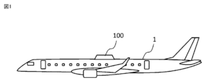
- FIG. 1 is a side view of an aircraft 1 equipped with the antenna device 100 according to the first embodiment.
- the antenna device 100 is an antenna device mounted on a moving body. For example, when mounted on an aircraft 1 for satellite communication, the antenna device 100 is attached to the top surface of the aircraft 1. Although the antenna device 100 is mounted on the aircraft 1 here, it may be mounted on another mobile body. When the antenna device 100 is mounted on another moving body, the antenna device 100 is attached to a portion capable of transmitting and receiving radio waves, such as a top surface portion or a side surface portion of the moving body.
- FIG. 2 is a cross-sectional view of the antenna device 100 according to the first embodiment. This cross section is a plane perpendicular to the mounting plane of the aircraft 1 on which the antenna device 100 is mounted.
- FIG. 3 is a top view of the antenna device 100 with the radome removed.
- the antenna device 100 includes an antenna unit 2 having an antenna element, a mount 3 provided with the antenna unit 2, a radome 4 for accommodating the antenna unit 2, and a skirt 5 provided on the mount 3.
- the antenna unit 2 includes an antenna element that transmits or receives radio waves.
- the antenna element is composed of a receiving antenna 21 and a transmitting antenna 22.
- the antenna element is composed of the receiving antenna 21 and the transmitting antenna 22, but may be composed of either one. Further, the antenna element may have a configuration in which the receiving antenna 21 and the transmitting antenna 22 are integrated.
- the receiving antenna 21 and the transmitting antenna 22 of the antenna unit 2 are provided on the mount 3, respectively.
- the receiving antenna 21 and the transmitting antenna 22 have an RFIC (Radio Frequency Integrated Circuit) 23, an RF (Radio Frequency) substrate 24, and an antenna base 25, respectively.
- RFIC Radio Frequency Integrated Circuit
- the RFIC 23 is provided on the surface of the RF substrate 24.
- the RFIC 23 is a module for satellite communication that drives an active electronic scanning array.
- the RF substrate 24 is a substrate on which the RFIC 23 is mounted.
- the RF board 24 has a function of radiating radio waves from the mounted RFIC 23.
- the active electronic scanning array can direct radio waves in any direction by electronic scanning. Therefore, by providing the RFIC 23, the antenna device 100 does not need to mechanically drive the antenna unit 2 when tracking the satellite and directing radio waves in an arbitrary direction in order to communicate with the satellite.
- An antenna base 25 is provided between the antenna element and the mount 3. Specifically, the antenna base 25 is provided between the RFIC 23 of the receiving antenna 21 and the mount 3. Similarly, the antenna base 25 is provided between the RFIC 23 of the transmitting antenna 22 and the mount 3.
- the antenna base 25 is a member for efficiently transferring the heat generated by the RFIC 23 and the RF substrate 24 of the antenna unit 2 to the mount 3.
- the antenna base 25 is made of a metal material having high thermal conductivity such as aluminum and copper. The heat transferred from the RFIC 23 and the RF substrate 24 to the antenna base 25 is diffused throughout the antenna base 25. Since the antenna base 25 is made of a metal material, the antenna device 100 can strongly support the mount 3 even when a load is applied from the outside due to vibration or the like. Therefore, the antenna base 25 also has a role of preventing the RFIC 23 and the RF substrate 24 from warping.
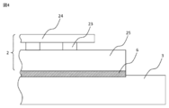
- FIG. 4 is an enlarged view of a portion where the antenna portion 2 and the mount 3 of the antenna device 100 according to the first embodiment are joined.
- the antenna base 25 and the mount 3 are preferably fastened in close contact with each other.
- heat loss can be reduced when the heat generated from the RFIC 23 and the RF substrate 24 is transmitted to the mount 3.
- the connection surface between the antenna base 25 and the mount 3 is preferably processed so that there is no surface unevenness.
- heat loss can be further reduced when the heat generated from the RFIC 23 and the RF substrate 24 is transmitted to the mount 3.
- the TIM material 6 is a member that fills a small gap between the antenna base 25 and the mount 3.
- the thermal resistance can be reduced on the connection surface between the antenna base 25 and the mount 3.
- the mount 3 is a component that plays the role of a plate for installing the antenna portion 2 on the aircraft 1.
- the mount 3 is attached to the aircraft 1 with the mounting bracket 7.
- the mount 3 is made of a highly rigid metal material so as not to transmit the influence of disturbance due to vibration load, wind load, etc. to the antenna portion 2. Further, since the mount 3 is made of a metal material, it has a high thermal conductivity, and the heat transferred from the antenna portion 2 can be diffused to the entire mount 3.
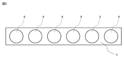
- FIG. 5 is a cross-sectional view of the mount 3 when the heat pipe 9 is formed on the mount 3 of the antenna device 100 according to the first embodiment.
- the mount 3 may be configured such that the heat pipe 9 is stretched around.
- the heat pipe 9 By forming the heat pipe 9 on the mount 3, the heat transferred from the RFIC 23 and the RF substrate 24 to the antenna base 25 can be efficiently diffused to the entire mount 3.
- the heat pipe 9 provided on the mount 3 is made of a metal material, the antenna device 100 can strongly support the mount 3 even when a load is applied from the outside due to vibration or the like. Therefore, it also has a role of preventing the RFIC 23 and the RF substrate 24 from warping.
- the mount 3 is a component having a first surface 31 and a side surface 32 connected to the first surface 31.
- the antenna portion 2 is provided on the first surface 31 of the mount 3.
- the antenna base 25 of the antenna unit 2 is provided on the first surface 31 of the mount 3, and the receiving antenna 21 and the transmitting antenna 22 are provided on the antenna base 25.
- the first surface 31 is an elliptical plate.
- the side surface 32 is a tubular member having an inclination, and is connected to the outer peripheral surface of the first surface 31 at an obtuse angle with respect to the first surface 31.
- the side surface 32 of the mount 3 has a smaller diameter from the end opposite to the side connected to the first surface 31 toward the end on the side connected to the first surface 31. Therefore, it is oval when viewed from the upper surface side and trapezoidal when viewed from the side surface side.
- the shape of the mount 3 may be any shape.
- the first surface 31 of the mount 3 has a suitable elliptical shape, but may have any shape such as a polygonal shape and a circular shape.
- the mount 3 may be a truncated cone-shaped member.
- FIG. 6 shows a truncated cone-shaped mount 3.
- the mount 3 shown in FIG. 6 has a shape in which the mount 3 shown in FIG. 2 does not have a cavity.
- the mount 3 has a first surface 31, a second surface 33 that is a surface opposite to the first surface 31, and a side surface 32 that connects the first surface 31 and the second surface. It is a structure to have.
- the radome 4 is a component for protecting the antenna portion 2 of the antenna device 100 from the external environment such as hot air, cold air, rain, and wind outside the radome 4.
- the radome 4 has a tubular shape with one end closed and the other end open. Further, the side surface of the radome 4 has an inclined shape, and the diameter decreases from the end portion on the open side toward the end portion on the closed side.
- the inclination of the radome 4 is an inclination along the shape of the side surface 32 of the mount 3.
- the radome 4 is fixed to the mount 3 with a fastening part 8.
- a part of the mount 3 is fitted inside the radome 4.
- the inner peripheral surface of the open end of the radome 4 is fixed to the side surface 32 of the mount 3.
- the fastening component 8 is attached from the outer peripheral surface side of the radome 4 toward the mount 3.
- the fastening component 8 is a component for fastening the radome 4 and the mount 3, and is a bolt, a rivet, or the like.
- the fastening component 8 is provided with measures to prevent loosening so that it will not loosen due to the load or vibration during flight of the aircraft 1.
- the first surface of the mount 3 is provided inside the radome 4.
- the end of the side surface 32 of the mount 3 connected to the first surface 31 is provided inside the radome 4.
- the end of the side surface 32 of the mount 3 opposite to the side connected to the first surface 31 is formed on the outside of the radome 4. That is, a part of the mount 3 is fitted into the radome 4, and a part of the mount 3 protrudes from the radome 4.
- the side surface 32 of the mount 3 has a surface to which the inner peripheral surface of the radome 4 is attached and a surface formed on the outside of the radome 4.
- the end of the side surface 32 of the mount 3 connected to the first surface 31 is provided inside the radome 4.
- the end of the side surface 32 of the mount 3 opposite to the side connected to the first surface 31 is formed on the outside of the radome 4.
- the first surface 31 is provided inside the radome 4, and the second surface 33 is provided outside the radome 4.
- FIG. 7 is a cross-sectional view of another configuration of the mount 3.
- the mount 3 may be configured to be entirely fitted into the radome 4.
- the first surface of the mount 3 is provided inside the radome 4.
- the side surface 32 of the mount 3 is also provided inside the radome 4.
- the radome 4 is made of a material having a high dielectric constant and a dielectric loss tangent so that radio waves emitted from the RF substrate 24 can be transmitted, and is formed with a predetermined thickness. Further, it is made of a material having strong strength so that the antenna portion 2 can be protected from an external environment such as a wind load and a collision of foreign matter.
- FIG. 8 is an enlarged cross-sectional view of the connection portion between the skirt 5 and the mount 3 of the antenna device 100 according to the first embodiment.
- the skirt 5 is a part for filling the space between the aircraft 1 and the mount 3.
- the skirt 5 has a shape that follows the shape of the portion of the mount 3 to which the skirt 5 is attached. Here, it has a tubular shape that follows the shape of the side surface 32 of the mount 3.
- the skirt 5 is provided so as to cover the surface of the side surface 32 of the mount 3 formed on the outside of the radome 4.
- the inner peripheral surface of the skirt 5 is attached on the side surface 32 of the mount 3 in contact with the surface formed on the outside of the radome 4.
- the skirt 5 and the mount 3 are fixed by the fastening part 8.
- the fastening component 8 is attached from the outer peripheral surface side of the skirt 5 toward the mount 3.
- the fastening component 8 is a bolt, a rivet, or the like.
- the skirt 5 is provided on the surface formed on the outside of the radome 4 of the mount 3 when the entire mount 3 is fitted into the radome 4 as shown in FIG.
- Other configurations of the skirt 5 are the same as those of FIG. 8 above.
- the skirt 5 is provided on the surface of the mount 3 formed on the outside of the radome 4.
- the skirt 5 may have a configuration in which at least a part thereof is connected to the mount 3, and is provided on a surface of the mount 3 formed inside the radome 4, such as between the mount 3 and the radome 4. May be good.
- the inner peripheral surface of the skirt 5 is fastened to the mount 3 via the TIM material 6. As a result, the gap between the skirt 5 and the mount 3 is filled, so that the skirt 5 and the mount 3 can be brought into close contact with each other.
- the end of the skirt 5 on the radome 4 side is connected to the radome 4 along the open end of the radome 4.
- the end of the skirt 5 on the opposite side of the radome 4 is connected to the aircraft 1 so as to follow the curved surface of the aircraft 1.
- the skirt 5 is attached to the aircraft 1 via the elastic material 10.
- the elastic body 10 is a member for filling a small gap between the skirt 5 and the aircraft 1.
- the elastic object 10 allows the skirt 5 and the aircraft 1 to be brought into close contact with each other, and the wind received by the antenna device 100 during the operation of the aircraft 1 enters the inside of the antenna device 100 from between the skirt 5 and the aircraft 1. , It is possible to prevent the generation of lift. Further, in order to fill the space between the aircraft 1 and the skirt 5, it is possible to prevent water from entering the inside of the antenna device 100 from between the skirt 5 and the aircraft 1.
- the connecting portion between the skirt 5 and the radome 4 is configured so that there is no step and the outer peripheral surface of the skirt 5 and the outer peripheral surface of the radome 4 are continuous surfaces. With this configuration, the air resistance of the antenna device 100 can be reduced. As shown in FIG. 9, the outer peripheral surface of the skirt 5 may be formed inside the outer peripheral surface of the radome 4.
- the skirt 5 is made of a metal material having high thermal conductivity, like the antenna base 25 and the mount 3.
- a slit-shaped heat radiating fin 51 is formed on the outer peripheral surface of the skirt 5 over the entire circumference of the outer peripheral surface.
- the heat radiating fin 51 dissipates heat from the antenna unit 2 to the outside of the antenna device 100.
- the skirt 5 itself has a structure capable of acting as a heat sink. Therefore, the heat transferred from the mount 3 to the skirt 5 can be released from the skirt 5 to the outside of the aircraft 1.
- the heat radiating fins 51 formed on the skirt 5 are provided with a plurality of slits in the circumferential direction of the skirt 5. By providing the slit in the circumferential direction of the skirt 5, the direction of the slit becomes the traveling direction of the aircraft 1, so that cooling can be performed more effectively.
- the heat radiating fins 51 formed on the skirt 5 are preferably provided with slits in the circumferential direction of the skirt 5, but may be slits in other directions or shapes as necessary. The direction and shape of the slit may be different depending on the location where the heat radiation fin 51 is provided. Further, here, the heat radiating fins 51 are formed over the entire circumference of the outer peripheral surface of the skirt 5, but may be provided only at a necessary location.
- the heat dissipation fins 51 may be provided only on a part of the outer peripheral surface of the skirt 5, such as forming the heat dissipation fins 51 only on both sides with respect to the traveling direction of the aircraft 1, which has high heat dissipation efficiency.
- FIG. 10 shows another configuration of the antenna device 100 according to the first embodiment.
- FIG. 10 is a top view of another configuration of the antenna device 100 with the radome 4 removed.
- the arrow 11 in the figure is the traveling direction of the aircraft 1.
- the shaded portion 53 of the skirt 5 in the drawing is a portion made of a metal material.
- the skirt 5 is made of a metal material having high thermal conductivity only in the shaded portions 53 on both sides with respect to the traveling direction of the aircraft 1, as shown in FIG.
- a portion other than the shaded portion 53 may be made of a lightweight material such as an elastic material.
- the heat radiation fins 51 are formed in the shaded portion 53 of the skirt 5.
- FIG. 11 is a diagram showing a heat dissipation flow of the antenna device 100.
- the arrows in the figure indicate the direction of heat dissipation.
- the heat generated by the transmitting antenna 22 and the receiving antenna 21 is transferred to the antenna base 25.
- the heat transferred to the antenna base 25 is diffused to the entire antenna base 25 and transferred to the mount 3 via the TIM material 6.
- the heat transferred to the mount 3 is diffused to the entire mount 3 and transferred to the skirt 5 via the TIM material 6.
- the heat transferred to the skirt 5 is finally released to the outside of the radome 4 from the heat radiation fins 51 provided on the outer periphery of the skirt 5.
- the antenna device 100 can efficiently transfer the heat generated from the receiving antenna 21 and the transmitting antenna 22 from the mount 3 to the skirt 5. Further, the skirt 5 itself can be used as a heat sink for heat dissipation. Therefore, the heat generated from the antenna portion can be efficiently dissipated to the outside of the radome 4 without providing a cooling device such as a fan inside the radome 4.
- the antenna device 100 is mounted on a moving body such as an aircraft 1, the antenna portion 2 is sealed by a radome 4 so that it does not come into direct contact with the outside air. Further, it is difficult to release heat from the antenna unit 2 to the airframe of the aircraft 1 due to the restrictions on the equipment.
- the heat inside the radome 4 can be dissipated from the skirt 5, so that the antenna device 100 does not become large. Further, it is possible to utilize the wind around the aircraft 1 in operation and the cold air in the sky for cooling the antenna device 100.
- FIG. 12 is a cross-sectional view of the antenna device 200 according to the second embodiment.
- FIG. 13 is an enlarged cross-sectional view of the connection portion between the skirt 5 and the mount 3 of the antenna device 200 according to the second embodiment.
- the antenna device 200 has a different configuration of the mount 3 and the skirt 5 of the antenna device 100 according to the first embodiment. Other configurations are substantially the same.
- the same or corresponding configurations as those described in the above-described embodiment will be designated by the same reference numerals, and the description of these configurations will not be repeated.
- the mount 3 and the skirt 5 are integrally formed.
- the mount 3 and the skirt 5 are made of the same material.
- the skirt 5 and the mount 3 are made of a metal material having high thermal conductivity.
- heat radiation fins 51 shaped like slits are formed on the outer peripheral surface of the skirt 5 over the entire circumference of the outer peripheral surface. ing. This makes it possible for the skirt 5 itself to play the role of a heat sink. Therefore, the heat transferred from the mount 3 to the skirt 5 can be released from the skirt 5 to the outside of the aircraft 1.
- the heat radiating fins 51 formed on the skirt 5 are provided with a plurality of slits in the circumferential direction of the skirt 5. By providing the slits in the circumferential direction of the skirt 5, the heat radiation fins 51 formed at positions on both sides with respect to the traveling direction of the aircraft 1 are cooled more effectively because the slit direction is the traveling direction of the aircraft 1. It can be performed.
- the heat radiating fins 51 formed on the skirt 5 are preferably provided with slits in the circumferential direction of the skirt 5, but may be slits in other directions or shapes as necessary. The direction and shape of the slit may be different depending on the location where the heat radiation fin 51 is provided.
- the heat radiation fins 51 are formed over the entire circumference of the outer peripheral surface of the skirt 5, but may be provided only at necessary locations.
- the heat dissipation fins 51 may be formed only on both sides with respect to the traveling direction of the aircraft 1, which has high heat dissipation efficiency, and may be provided only on a part of the outer peripheral surface of the skirt 5.
- the mount 3 and the skirt 5 may be integrally formed only at the portion of the skirt 5 where the heat radiation fins 51 are provided.
- the skirt 5 is made of a metal material having high thermal conductivity only on both sides with respect to the traveling direction of the aircraft 1, and other than that.
- the portion may be made of a lightweight material such as an elastic material.
- the heat radiation fins 51 are formed on the portion of the skirt 5 made of a metal material.
- only the portion of the skirt 5 made of a metal material is configured to integrally form the mount 3 and the skirt 5.
- FIG. 14 is a diagram showing a heat dissipation flow of the antenna device 200.
- the arrows in the figure indicate the direction of heat dissipation.
- the heat generated by the transmitting antenna 22 and the receiving antenna 21 is transferred to the antenna base 25.
- the heat transferred to the antenna base 25 is diffused to the entire antenna base 25 and transferred to the mount 3 via the TIM material 6.
- the heat transferred to the mount 3 is diffused to the entire mount 3 and transferred to the skirt 5 via the TIM material 6.
- the heat transferred to the skirt 5 is finally released to the outside of the radome 4 from the heat radiation fins 51 provided on the outer periphery of the skirt 5.
- the heat generated from the receiving antenna 21 and the transmitting antenna 22 can be efficiently transferred from the mount 3 to the skirt 5.
- the skirt 5 itself can be used as a heat sink for heat dissipation. Therefore, the heat generated from the antenna portion can be efficiently dissipated to the outside of the radome 4 without providing a cooling device such as a fan inside the radome 4.
- the antenna device 100 is mounted on a moving body such as an aircraft 1, the antenna portion 2 is sealed by a radome 4 so that it does not come into direct contact with the outside air. Further, it is difficult to release heat from the antenna unit 2 to the airframe of the aircraft 1 due to the restrictions on the equipment.
- the heat inside the radome 4 can be dissipated from the skirt 5, so that the antenna device 100 does not become large. Further, it is possible to utilize the wind around the aircraft 1 in operation and the cold air in the sky for cooling the antenna device 100.
- mount 3 and the skirt 5 are integrally formed, it is possible to have a configuration in which heat dissipation is improved when heat is transferred from the mount 3 to the skirt 5 as compared with the antenna device 100. .. Further, it is not necessary to fix the mount 3 and the skirt 5 with the fastening parts 8, which facilitates assembly. Further, since the fastening parts 8 and the TIM material 6 are not required, the number of component parts can be reduced.
- FIG. 15 is a cross-sectional view of the antenna device 300 according to the second embodiment.
- FIG. 16 is an enlarged cross-sectional view of the connection portion between the skirt 5 and the mount 3 of the antenna device 300 according to the second embodiment.
- the antenna device 300 has a different configuration of the radome 4 and the skirt 5 of the antenna device 100 according to the first embodiment. Other configurations are substantially the same.
- the same or corresponding configurations as those described in the above-described embodiment will be designated by the same reference numerals, and the description of these configurations will not be repeated.
- a part of the skirt 5 is integrally formed with the radome 4.
- a part of the skirt 5 integrally formed with the radome 4 is a metal block 52 formed of a metal material.
- the metal block 52 is integrally molded with the radome 4 at the stage of manufacturing the radome 4.
- heat radiation fins 51 shaped like slits are formed on the outer peripheral surface of the skirt 5 over the entire circumference of the outer peripheral surface. ing.
- a heat radiation fin 51 shaped like a slit may also be formed in the portion of the metal block 52. This makes it possible for the skirt 5 itself to play the role of a heat sink. Therefore, the heat transferred from the mount 3 to the skirt 5 can be released from the skirt 5 to the outside of the aircraft 1.
- the heat radiating fins 51 formed on the skirt 5 are provided with a plurality of slits in the circumferential direction of the skirt 5. By providing the slits in the circumferential direction of the skirt 5, the heat radiation fins 51 formed at positions on both sides with respect to the traveling direction of the aircraft 1 are cooled more effectively because the slit direction is the traveling direction of the aircraft 1. It can be performed.
- the heat radiating fins 51 formed on the skirt 5 are preferably provided with slits in the circumferential direction of the skirt 5 as described above, but may be slits in other directions or shapes as needed. The direction and shape of the slit may be different depending on the location where the heat radiation fin 51 is provided.
- the heat radiation fins 51 are formed over the entire circumference of the outer peripheral surface of the skirt 5, but may be provided only at necessary locations.
- the heat dissipation fins 51 may be formed only on both sides with respect to the traveling direction of the aircraft 1 having high heat dissipation efficiency, and may be provided only on a part of the outer peripheral surface of the skirt 5.
- the skirt 5 is made of a metal material having high thermal conductivity only on both sides with respect to the traveling direction of the aircraft 1, and other than that.
- the portion may be made of a lightweight material such as an elastic material.
- the heat radiation fins 51 are formed on the portion of the skirt 5 made of a metal material.
- FIG. 17 is a diagram showing a heat dissipation flow of the antenna device 300.
- the arrows in the figure indicate the direction of heat dissipation.
- the heat generated by the transmitting antenna 22 and the receiving antenna 21 is transferred to the antenna base 25.
- the heat transferred to the antenna base 25 is diffused to the entire antenna base 25 and transferred to the mount 3 via the TIM material 6.
- the heat transferred to the mount 3 is diffused to the entire mount 3 and transferred to the skirt 5 via the TIM material 6.
- the heat transferred to the skirt 5 is finally released to the outside of the radome 4 from the heat radiation fins 51 provided on the outer periphery of the skirt 5.
- the antenna device 300 configured in this way, the heat generated from the receiving antenna 21 and the transmitting antenna 22 can be efficiently transferred from the mount 3 to the skirt 5. Further, the skirt 5 itself can be used as a heat sink for heat dissipation. Therefore, the heat generated from the antenna portion can be efficiently dissipated to the outside of the radome 4 without providing a cooling device such as a fan inside the radome 4.
- the antenna device 100 is mounted on a moving body such as an aircraft 1, the antenna portion 2 is sealed by a radome 4 so that it does not come into direct contact with the outside air. Further, it is difficult to release heat from the antenna unit 2 to the airframe of the aircraft 1 due to the restrictions on the equipment.
- the heat inside the radome 4 can be dissipated from the skirt 5, so that the antenna device 100 does not become large. Further, it is possible to utilize the wind around the aircraft 1 in operation and the cold air in the sky for cooling the antenna device 100.
- the radome 4 portion can also have a heat dissipation effect. With this configuration, it is possible to have a configuration in which heat dissipation is improved when heat is transferred from the mount 3 to the skirt 5 as compared with the antenna device 100.
Landscapes
- Physics & Mathematics (AREA)
- Engineering & Computer Science (AREA)
- Thermal Sciences (AREA)
- Microelectronics & Electronic Packaging (AREA)
- Astronomy & Astrophysics (AREA)
- Aviation & Aerospace Engineering (AREA)
- General Physics & Mathematics (AREA)
- Remote Sensing (AREA)
- Details Of Aerials (AREA)
- Cooling Or The Like Of Electrical Apparatus (AREA)
- Cooling Or The Like Of Semiconductors Or Solid State Devices (AREA)
Priority Applications (3)
| Application Number | Priority Date | Filing Date | Title |
|---|---|---|---|
| US17/609,420 US12095136B2 (en) | 2019-06-28 | 2020-04-09 | Antenna apparatus |
| EP20833463.1A EP3993155A4 (en) | 2019-06-28 | 2020-04-09 | ANTENNA DEVICE |
| JP2021527399A JP7119228B2 (ja) | 2019-06-28 | 2020-04-09 | アンテナ装置 |
Applications Claiming Priority (2)
| Application Number | Priority Date | Filing Date | Title |
|---|---|---|---|
| JP2019121090 | 2019-06-28 | ||
| JP2019-121090 | 2019-06-28 |
Publications (1)
| Publication Number | Publication Date |
|---|---|
| WO2020261706A1 true WO2020261706A1 (ja) | 2020-12-30 |
Family
ID=74061594
Family Applications (1)
| Application Number | Title | Priority Date | Filing Date |
|---|---|---|---|
| PCT/JP2020/015956 Ceased WO2020261706A1 (ja) | 2019-06-28 | 2020-04-09 | アンテナ装置 |
Country Status (4)
| Country | Link |
|---|---|
| US (1) | US12095136B2 (https=) |
| EP (1) | EP3993155A4 (https=) |
| JP (1) | JP7119228B2 (https=) |
| WO (1) | WO2020261706A1 (https=) |
Cited By (4)
| Publication number | Priority date | Publication date | Assignee | Title |
|---|---|---|---|---|
| CN115016600A (zh) * | 2022-03-15 | 2022-09-06 | 北京小米移动软件有限公司 | 笔记本电脑 |
| WO2023127899A1 (ja) * | 2021-12-28 | 2023-07-06 | 三菱電機株式会社 | アンテナ装置 |
| WO2023168924A1 (en) * | 2022-03-08 | 2023-09-14 | Commscope Technologies Llc | Reflector assemblies for active antenna units and active antenna units and base station antennas with the reflector assemblies |
| US12469948B2 (en) | 2022-10-05 | 2025-11-11 | Outdoor Wireless Networks LLC | Active antenna units and base station antennas with heat dissipation members |
Families Citing this family (4)
| Publication number | Priority date | Publication date | Assignee | Title |
|---|---|---|---|---|
| US20220354020A1 (en) * | 2019-09-06 | 2022-11-03 | Carlisle Interconnect Technologies, Inc. | Mounting System For Mounting An Element To An Aircraft Surface |
| EP4270634A4 (en) * | 2020-12-28 | 2024-11-06 | Kyocera Corporation | Antenna device |
| EP4673997A1 (en) * | 2023-06-15 | 2026-01-07 | Safran Passenger Innovations, LLC | Semi-transparent radome for in-flight connectivity terminal |
| CN117039390B (zh) * | 2023-10-09 | 2023-12-29 | 成都天锐星通科技有限公司 | 一种相控阵天线及通讯设备 |
Citations (9)
| Publication number | Priority date | Publication date | Assignee | Title |
|---|---|---|---|---|
| JPH0487402A (ja) * | 1990-07-31 | 1992-03-19 | Nec Corp | アンテナ装置 |
| JP2000323910A (ja) * | 1999-05-11 | 2000-11-24 | Mitsubishi Electric Corp | アンテナ装置の冷却構造 |
| JP2003110330A (ja) * | 2001-10-02 | 2003-04-11 | Mitsubishi Electric Corp | アンテナ装置 |
| JP2003298270A (ja) | 2002-03-29 | 2003-10-17 | Mitsubishi Electric Corp | アンテナ装置 |
| JP2012109670A (ja) * | 2010-11-15 | 2012-06-07 | Mitsubishi Electric Corp | 高周波モジュール及びこれを用いたアレイアンテナ装置 |
| US20120326915A1 (en) * | 2010-03-09 | 2012-12-27 | Pti Industries, Inc. | Housing for aircraft mounted components |
| JP2013131860A (ja) * | 2011-12-20 | 2013-07-04 | Toshiba Corp | アンテナ装置 |
| JP2016539606A (ja) | 2013-11-11 | 2016-12-15 | ゴーゴー・エルエルシー | 低無線信号減衰量のローカルエリアを有するレードーム |
| JP2017152810A (ja) * | 2016-02-23 | 2017-08-31 | Necプラットフォームズ株式会社 | 車載用アンテナ装置および車載用アンテナ装置の放熱方法 |
Family Cites Families (7)
| Publication number | Priority date | Publication date | Assignee | Title |
|---|---|---|---|---|
| CA2001013C (en) * | 1988-10-19 | 1995-04-18 | Toshikiyo Hirata | Array antenna system |
| KR100995082B1 (ko) * | 2008-08-13 | 2010-11-18 | 한국전자통신연구원 | 안테나 모듈의 온도 제어 시스템 |
| BR112012013364A8 (pt) * | 2009-12-02 | 2018-02-06 | Andrew Llc | Antena de painel que tem caixa vedada de rádio |
| KR101769524B1 (ko) * | 2012-11-16 | 2017-08-21 | 주식회사 케이엠더블유 | 이동통신 시스템의 소형 기지국 장치 |
| US9608321B2 (en) | 2013-11-11 | 2017-03-28 | Gogo Llc | Radome having localized areas of reduced radio signal attenuation |
| CN110492216A (zh) * | 2018-05-15 | 2019-11-22 | 康普技术有限责任公司 | 具有完全内嵌无线电和带集成散热结构的壳体的基站天线 |
| KR102290036B1 (ko) * | 2019-05-15 | 2021-08-18 | 주식회사 케이엠더블유 | 안테나 장치 |
-
2020
- 2020-04-09 EP EP20833463.1A patent/EP3993155A4/en active Pending
- 2020-04-09 WO PCT/JP2020/015956 patent/WO2020261706A1/ja not_active Ceased
- 2020-04-09 US US17/609,420 patent/US12095136B2/en active Active
- 2020-04-09 JP JP2021527399A patent/JP7119228B2/ja active Active
Patent Citations (9)
| Publication number | Priority date | Publication date | Assignee | Title |
|---|---|---|---|---|
| JPH0487402A (ja) * | 1990-07-31 | 1992-03-19 | Nec Corp | アンテナ装置 |
| JP2000323910A (ja) * | 1999-05-11 | 2000-11-24 | Mitsubishi Electric Corp | アンテナ装置の冷却構造 |
| JP2003110330A (ja) * | 2001-10-02 | 2003-04-11 | Mitsubishi Electric Corp | アンテナ装置 |
| JP2003298270A (ja) | 2002-03-29 | 2003-10-17 | Mitsubishi Electric Corp | アンテナ装置 |
| US20120326915A1 (en) * | 2010-03-09 | 2012-12-27 | Pti Industries, Inc. | Housing for aircraft mounted components |
| JP2012109670A (ja) * | 2010-11-15 | 2012-06-07 | Mitsubishi Electric Corp | 高周波モジュール及びこれを用いたアレイアンテナ装置 |
| JP2013131860A (ja) * | 2011-12-20 | 2013-07-04 | Toshiba Corp | アンテナ装置 |
| JP2016539606A (ja) | 2013-11-11 | 2016-12-15 | ゴーゴー・エルエルシー | 低無線信号減衰量のローカルエリアを有するレードーム |
| JP2017152810A (ja) * | 2016-02-23 | 2017-08-31 | Necプラットフォームズ株式会社 | 車載用アンテナ装置および車載用アンテナ装置の放熱方法 |
Non-Patent Citations (1)
| Title |
|---|
| See also references of EP3993155A4 |
Cited By (7)
| Publication number | Priority date | Publication date | Assignee | Title |
|---|---|---|---|---|
| WO2023127899A1 (ja) * | 2021-12-28 | 2023-07-06 | 三菱電機株式会社 | アンテナ装置 |
| JP7341377B1 (ja) * | 2021-12-28 | 2023-09-08 | 三菱電機株式会社 | アンテナ装置 |
| US12218400B2 (en) | 2021-12-28 | 2025-02-04 | Mitsubishi Electric Corporation | Antenna device |
| EP4459792A4 (en) * | 2021-12-28 | 2025-05-07 | Mitsubishi Electric Corporation | ANTENNA DEVICE |
| WO2023168924A1 (en) * | 2022-03-08 | 2023-09-14 | Commscope Technologies Llc | Reflector assemblies for active antenna units and active antenna units and base station antennas with the reflector assemblies |
| CN115016600A (zh) * | 2022-03-15 | 2022-09-06 | 北京小米移动软件有限公司 | 笔记本电脑 |
| US12469948B2 (en) | 2022-10-05 | 2025-11-11 | Outdoor Wireless Networks LLC | Active antenna units and base station antennas with heat dissipation members |
Also Published As
| Publication number | Publication date |
|---|---|
| JP7119228B2 (ja) | 2022-08-16 |
| EP3993155A4 (en) | 2022-09-07 |
| EP3993155A1 (en) | 2022-05-04 |
| US12095136B2 (en) | 2024-09-17 |
| US20220223992A1 (en) | 2022-07-14 |
| JPWO2020261706A1 (https=) | 2020-12-30 |
Similar Documents
| Publication | Publication Date | Title |
|---|---|---|
| JP7119228B2 (ja) | アンテナ装置 | |
| US10331016B2 (en) | Image capturing module | |
| JPWO2020261706A5 (https=) | ||
| US20230007808A1 (en) | Telecommunications housing with improved thermal load management | |
| JP7050958B2 (ja) | アンテナ装置 | |
| US6950306B2 (en) | Connection frame for fan | |
| JP2019147421A (ja) | 車両用アンテナ装置 | |
| JP4564507B2 (ja) | アンテナ装置とアンテナ複合ユニット | |
| WO2021186568A1 (ja) | アンテナ装置 | |
| US20210336318A1 (en) | Communication device for vehicle | |
| US12218400B2 (en) | Antenna device | |
| KR101648831B1 (ko) | 경량화한 중계기 함체 | |
| JP5920122B2 (ja) | 車載用アンテナ装置 | |
| JP2007192804A (ja) | レーダ装置 | |
| JP2003298270A (ja) | アンテナ装置 | |
| KR102555901B1 (ko) | 방열부를 구비하는 초소형 위성 | |
| KR20090119206A (ko) | 무선통신기기의 함체장치의 열방출 구조 | |
| US20060274500A1 (en) | Heat radiating structure for CPU | |
| WO2022145206A1 (ja) | アンテナ装置 | |
| JP2019140429A (ja) | パラボラアンテナ装置の導風装置、パラボラアンテナ装置およびパラボラアンテナ装置の冷却方法 | |
| JPH02246142A (ja) | 半導体装置 | |
| JP7697740B2 (ja) | アンテナ装置及びレドーム | |
| US20240087977A1 (en) | Integrated circuit package heat sink | |
| JP7042857B2 (ja) | 電力変換装置 | |
| JPH06104309A (ja) | 半導体装置 |
Legal Events
| Date | Code | Title | Description |
|---|---|---|---|
| 121 | Ep: the epo has been informed by wipo that ep was designated in this application |
Ref document number: 20833463 Country of ref document: EP Kind code of ref document: A1 |
|
| ENP | Entry into the national phase |
Ref document number: 2021527399 Country of ref document: JP Kind code of ref document: A |
|
| NENP | Non-entry into the national phase |
Ref country code: DE |
|
| WWE | Wipo information: entry into national phase |
Ref document number: 2020833463 Country of ref document: EP |