WO2020261706A1 - アンテナ装置 - Google Patents
アンテナ装置 Download PDFInfo
- Publication number
- WO2020261706A1 WO2020261706A1 PCT/JP2020/015956 JP2020015956W WO2020261706A1 WO 2020261706 A1 WO2020261706 A1 WO 2020261706A1 JP 2020015956 W JP2020015956 W JP 2020015956W WO 2020261706 A1 WO2020261706 A1 WO 2020261706A1
- Authority
- WO
- WIPO (PCT)
- Prior art keywords
- mount
- skirt
- antenna
- radome
- antenna device
- Prior art date
Links
Images


Classifications
-
- H—ELECTRICITY
- H01—ELECTRIC ELEMENTS
- H01Q—ANTENNAS, i.e. RADIO AERIALS
- H01Q1/00—Details of, or arrangements associated with, antennas
- H01Q1/02—Arrangements for de-icing; Arrangements for drying-out ; Arrangements for cooling; Arrangements for preventing corrosion
-
- H—ELECTRICITY
- H01—ELECTRIC ELEMENTS
- H01Q—ANTENNAS, i.e. RADIO AERIALS
- H01Q1/00—Details of, or arrangements associated with, antennas
- H01Q1/42—Housings not intimately mechanically associated with radiating elements, e.g. radome
-
- H—ELECTRICITY
- H05—ELECTRIC TECHNIQUES NOT OTHERWISE PROVIDED FOR
- H05K—PRINTED CIRCUITS; CASINGS OR CONSTRUCTIONAL DETAILS OF ELECTRIC APPARATUS; MANUFACTURE OF ASSEMBLAGES OF ELECTRICAL COMPONENTS
- H05K7/00—Constructional details common to different types of electric apparatus
- H05K7/20—Modifications to facilitate cooling, ventilating, or heating
- H05K7/2039—Modifications to facilitate cooling, ventilating, or heating characterised by the heat transfer by conduction from the heat generating element to a dissipating body
- H05K7/20436—Inner thermal coupling elements in heat dissipating housings, e.g. protrusions or depressions integrally formed in the housing
- H05K7/20445—Inner thermal coupling elements in heat dissipating housings, e.g. protrusions or depressions integrally formed in the housing the coupling element being an additional piece, e.g. thermal standoff
-
- H—ELECTRICITY
- H01—ELECTRIC ELEMENTS
- H01Q—ANTENNAS, i.e. RADIO AERIALS
- H01Q1/00—Details of, or arrangements associated with, antennas
- H01Q1/27—Adaptation for use in or on movable bodies
- H01Q1/28—Adaptation for use in or on aircraft, missiles, satellites, or balloons
Definitions
- the present disclosure relates to an antenna device having a heat dissipation structure.
- the antenna device mounted on a moving body such as an aircraft has a small cross-sectional area when viewed from the nose direction in order to reduce air resistance (see, for example, Patent Document 1).
- a phased array method is used as a technique for reducing the height of the antenna device in order to reduce the cross-sectional area seen from the nose direction.
- exhaust heat from the antenna device is performed by air cooling using heat radiation fins provided in a heat pipe (see, for example, Patent Document 2).
- the antenna device described in Patent Document 1 since the antenna device is mounted on a moving body, the antenna portion is covered with a radome and does not come into direct contact with the outside air. Therefore, in order to cool the antenna portion, it is necessary to provide a cooling device such as a fan inside the radome, and there is a problem that it is difficult to reduce the height of the antenna device. Further, even in the antenna device described in Patent Document 2, in order to cool the antenna portion, a space for providing a heat pipe inside the radome is required, and it is difficult to reduce the height of the antenna device. There are challenges.
- the present disclosure has been made to solve the above problems, and an object of the present invention is to obtain an antenna device capable of cooling with a high heat dissipation effect even when the height of the antenna device is reduced. And.
- the antenna device includes an antenna element, a mount provided with the antenna element, a radome for accommodating the antenna element, and a skirt provided on the mount, and the side surface of the mount is on the inner peripheral surface of the radome. It has an attached surface, and the skirt is characterized in that heat radiation fins are formed on the outer peripheral surface to dissipate heat from the antenna element transmitted through the mount to the outside.
- an antenna device capable of cooling with a high heat dissipation effect even when the height of the antenna device is reduced.
- FIG. 5 is a side view of an aircraft equipped with the antenna device according to the first embodiment. It is sectional drawing of the antenna device which concerns on Embodiment 1. FIG. It is the top view which removed the radome of the antenna device which concerns on Embodiment 1. FIG. It is an enlarged view of the part where the antenna part and the mount of the antenna device which concerns on Embodiment 1 are joined. It is sectional drawing of the mount when the heat pipe is formed in the mount of the antenna device which concerns on Embodiment 1. FIG. It is sectional drawing which shows the other structure of the antenna device which concerns on Embodiment 1. FIG. It is sectional drawing which shows the other structure of the antenna device which concerns on Embodiment 1. FIG. FIG. FIG. FIG.
- FIG. 5 is an enlarged cross-sectional view of a connection portion between a skirt and a mount of the antenna device according to the first embodiment.
- FIG. 5 is an enlarged cross-sectional view of a connection portion between a skirt and a mount of the antenna device according to the first embodiment. It is a top view which shows the other structure of the antenna device which concerns on Embodiment 1.
- FIG. It is a figure which shows the flow of heat dissipation of the antenna device which concerns on Embodiment 1.
- FIG. It is sectional drawing of the antenna device which concerns on Embodiment 2.
- FIG. FIG. 5 is an enlarged cross-sectional view of a connection portion between a skirt and a mount of the antenna device according to the second embodiment.
- FIG. 5 is an enlarged cross-sectional view of a connection portion between a skirt and a mount of the antenna device according to the third embodiment. It is a figure which shows the flow of heat dissipation of the antenna device which concerns on Embodiment 3.
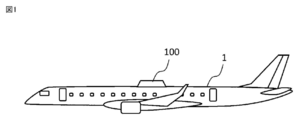
- FIG. 1 is a side view of an aircraft 1 equipped with the antenna device 100 according to the first embodiment.
- the antenna device 100 is an antenna device mounted on a moving body. For example, when mounted on an aircraft 1 for satellite communication, the antenna device 100 is attached to the top surface of the aircraft 1. Although the antenna device 100 is mounted on the aircraft 1 here, it may be mounted on another mobile body. When the antenna device 100 is mounted on another moving body, the antenna device 100 is attached to a portion capable of transmitting and receiving radio waves, such as a top surface portion or a side surface portion of the moving body.
- FIG. 2 is a cross-sectional view of the antenna device 100 according to the first embodiment. This cross section is a plane perpendicular to the mounting plane of the aircraft 1 on which the antenna device 100 is mounted.
- FIG. 3 is a top view of the antenna device 100 with the radome removed.
- the antenna device 100 includes an antenna unit 2 having an antenna element, a mount 3 provided with the antenna unit 2, a radome 4 for accommodating the antenna unit 2, and a skirt 5 provided on the mount 3.
- the antenna unit 2 includes an antenna element that transmits or receives radio waves.
- the antenna element is composed of a receiving antenna 21 and a transmitting antenna 22.
- the antenna element is composed of the receiving antenna 21 and the transmitting antenna 22, but may be composed of either one. Further, the antenna element may have a configuration in which the receiving antenna 21 and the transmitting antenna 22 are integrated.
- the receiving antenna 21 and the transmitting antenna 22 of the antenna unit 2 are provided on the mount 3, respectively.
- the receiving antenna 21 and the transmitting antenna 22 have an RFIC (Radio Frequency Integrated Circuit) 23, an RF (Radio Frequency) substrate 24, and an antenna base 25, respectively.
- RFIC Radio Frequency Integrated Circuit
- the RFIC 23 is provided on the surface of the RF substrate 24.
- the RFIC 23 is a module for satellite communication that drives an active electronic scanning array.
- the RF substrate 24 is a substrate on which the RFIC 23 is mounted.
- the RF board 24 has a function of radiating radio waves from the mounted RFIC 23.
- the active electronic scanning array can direct radio waves in any direction by electronic scanning. Therefore, by providing the RFIC 23, the antenna device 100 does not need to mechanically drive the antenna unit 2 when tracking the satellite and directing radio waves in an arbitrary direction in order to communicate with the satellite.
- An antenna base 25 is provided between the antenna element and the mount 3. Specifically, the antenna base 25 is provided between the RFIC 23 of the receiving antenna 21 and the mount 3. Similarly, the antenna base 25 is provided between the RFIC 23 of the transmitting antenna 22 and the mount 3.
- the antenna base 25 is a member for efficiently transferring the heat generated by the RFIC 23 and the RF substrate 24 of the antenna unit 2 to the mount 3.
- the antenna base 25 is made of a metal material having high thermal conductivity such as aluminum and copper. The heat transferred from the RFIC 23 and the RF substrate 24 to the antenna base 25 is diffused throughout the antenna base 25. Since the antenna base 25 is made of a metal material, the antenna device 100 can strongly support the mount 3 even when a load is applied from the outside due to vibration or the like. Therefore, the antenna base 25 also has a role of preventing the RFIC 23 and the RF substrate 24 from warping.
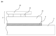
- FIG. 4 is an enlarged view of a portion where the antenna portion 2 and the mount 3 of the antenna device 100 according to the first embodiment are joined.
- the antenna base 25 and the mount 3 are preferably fastened in close contact with each other.
- heat loss can be reduced when the heat generated from the RFIC 23 and the RF substrate 24 is transmitted to the mount 3.
- the connection surface between the antenna base 25 and the mount 3 is preferably processed so that there is no surface unevenness.
- heat loss can be further reduced when the heat generated from the RFIC 23 and the RF substrate 24 is transmitted to the mount 3.
- the TIM material 6 is a member that fills a small gap between the antenna base 25 and the mount 3.
- the thermal resistance can be reduced on the connection surface between the antenna base 25 and the mount 3.
- the mount 3 is a component that plays the role of a plate for installing the antenna portion 2 on the aircraft 1.
- the mount 3 is attached to the aircraft 1 with the mounting bracket 7.
- the mount 3 is made of a highly rigid metal material so as not to transmit the influence of disturbance due to vibration load, wind load, etc. to the antenna portion 2. Further, since the mount 3 is made of a metal material, it has a high thermal conductivity, and the heat transferred from the antenna portion 2 can be diffused to the entire mount 3.
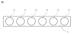
- FIG. 5 is a cross-sectional view of the mount 3 when the heat pipe 9 is formed on the mount 3 of the antenna device 100 according to the first embodiment.
- the mount 3 may be configured such that the heat pipe 9 is stretched around.
- the heat pipe 9 By forming the heat pipe 9 on the mount 3, the heat transferred from the RFIC 23 and the RF substrate 24 to the antenna base 25 can be efficiently diffused to the entire mount 3.
- the heat pipe 9 provided on the mount 3 is made of a metal material, the antenna device 100 can strongly support the mount 3 even when a load is applied from the outside due to vibration or the like. Therefore, it also has a role of preventing the RFIC 23 and the RF substrate 24 from warping.
- the mount 3 is a component having a first surface 31 and a side surface 32 connected to the first surface 31.
- the antenna portion 2 is provided on the first surface 31 of the mount 3.
- the antenna base 25 of the antenna unit 2 is provided on the first surface 31 of the mount 3, and the receiving antenna 21 and the transmitting antenna 22 are provided on the antenna base 25.
- the first surface 31 is an elliptical plate.
- the side surface 32 is a tubular member having an inclination, and is connected to the outer peripheral surface of the first surface 31 at an obtuse angle with respect to the first surface 31.
- the side surface 32 of the mount 3 has a smaller diameter from the end opposite to the side connected to the first surface 31 toward the end on the side connected to the first surface 31. Therefore, it is oval when viewed from the upper surface side and trapezoidal when viewed from the side surface side.
- the shape of the mount 3 may be any shape.
- the first surface 31 of the mount 3 has a suitable elliptical shape, but may have any shape such as a polygonal shape and a circular shape.
- the mount 3 may be a truncated cone-shaped member.
- FIG. 6 shows a truncated cone-shaped mount 3.
- the mount 3 shown in FIG. 6 has a shape in which the mount 3 shown in FIG. 2 does not have a cavity.
- the mount 3 has a first surface 31, a second surface 33 that is a surface opposite to the first surface 31, and a side surface 32 that connects the first surface 31 and the second surface. It is a structure to have.
- the radome 4 is a component for protecting the antenna portion 2 of the antenna device 100 from the external environment such as hot air, cold air, rain, and wind outside the radome 4.
- the radome 4 has a tubular shape with one end closed and the other end open. Further, the side surface of the radome 4 has an inclined shape, and the diameter decreases from the end portion on the open side toward the end portion on the closed side.
- the inclination of the radome 4 is an inclination along the shape of the side surface 32 of the mount 3.
- the radome 4 is fixed to the mount 3 with a fastening part 8.
- a part of the mount 3 is fitted inside the radome 4.
- the inner peripheral surface of the open end of the radome 4 is fixed to the side surface 32 of the mount 3.
- the fastening component 8 is attached from the outer peripheral surface side of the radome 4 toward the mount 3.
- the fastening component 8 is a component for fastening the radome 4 and the mount 3, and is a bolt, a rivet, or the like.
- the fastening component 8 is provided with measures to prevent loosening so that it will not loosen due to the load or vibration during flight of the aircraft 1.
- the first surface of the mount 3 is provided inside the radome 4.
- the end of the side surface 32 of the mount 3 connected to the first surface 31 is provided inside the radome 4.
- the end of the side surface 32 of the mount 3 opposite to the side connected to the first surface 31 is formed on the outside of the radome 4. That is, a part of the mount 3 is fitted into the radome 4, and a part of the mount 3 protrudes from the radome 4.
- the side surface 32 of the mount 3 has a surface to which the inner peripheral surface of the radome 4 is attached and a surface formed on the outside of the radome 4.
- the end of the side surface 32 of the mount 3 connected to the first surface 31 is provided inside the radome 4.
- the end of the side surface 32 of the mount 3 opposite to the side connected to the first surface 31 is formed on the outside of the radome 4.
- the first surface 31 is provided inside the radome 4, and the second surface 33 is provided outside the radome 4.
- FIG. 7 is a cross-sectional view of another configuration of the mount 3.
- the mount 3 may be configured to be entirely fitted into the radome 4.
- the first surface of the mount 3 is provided inside the radome 4.
- the side surface 32 of the mount 3 is also provided inside the radome 4.
- the radome 4 is made of a material having a high dielectric constant and a dielectric loss tangent so that radio waves emitted from the RF substrate 24 can be transmitted, and is formed with a predetermined thickness. Further, it is made of a material having strong strength so that the antenna portion 2 can be protected from an external environment such as a wind load and a collision of foreign matter.
- FIG. 8 is an enlarged cross-sectional view of the connection portion between the skirt 5 and the mount 3 of the antenna device 100 according to the first embodiment.
- the skirt 5 is a part for filling the space between the aircraft 1 and the mount 3.
- the skirt 5 has a shape that follows the shape of the portion of the mount 3 to which the skirt 5 is attached. Here, it has a tubular shape that follows the shape of the side surface 32 of the mount 3.
- the skirt 5 is provided so as to cover the surface of the side surface 32 of the mount 3 formed on the outside of the radome 4.
- the inner peripheral surface of the skirt 5 is attached on the side surface 32 of the mount 3 in contact with the surface formed on the outside of the radome 4.
- the skirt 5 and the mount 3 are fixed by the fastening part 8.
- the fastening component 8 is attached from the outer peripheral surface side of the skirt 5 toward the mount 3.
- the fastening component 8 is a bolt, a rivet, or the like.
- the skirt 5 is provided on the surface formed on the outside of the radome 4 of the mount 3 when the entire mount 3 is fitted into the radome 4 as shown in FIG.
- Other configurations of the skirt 5 are the same as those of FIG. 8 above.
- the skirt 5 is provided on the surface of the mount 3 formed on the outside of the radome 4.
- the skirt 5 may have a configuration in which at least a part thereof is connected to the mount 3, and is provided on a surface of the mount 3 formed inside the radome 4, such as between the mount 3 and the radome 4. May be good.
- the inner peripheral surface of the skirt 5 is fastened to the mount 3 via the TIM material 6. As a result, the gap between the skirt 5 and the mount 3 is filled, so that the skirt 5 and the mount 3 can be brought into close contact with each other.
- the end of the skirt 5 on the radome 4 side is connected to the radome 4 along the open end of the radome 4.
- the end of the skirt 5 on the opposite side of the radome 4 is connected to the aircraft 1 so as to follow the curved surface of the aircraft 1.
- the skirt 5 is attached to the aircraft 1 via the elastic material 10.
- the elastic body 10 is a member for filling a small gap between the skirt 5 and the aircraft 1.
- the elastic object 10 allows the skirt 5 and the aircraft 1 to be brought into close contact with each other, and the wind received by the antenna device 100 during the operation of the aircraft 1 enters the inside of the antenna device 100 from between the skirt 5 and the aircraft 1. , It is possible to prevent the generation of lift. Further, in order to fill the space between the aircraft 1 and the skirt 5, it is possible to prevent water from entering the inside of the antenna device 100 from between the skirt 5 and the aircraft 1.
- the connecting portion between the skirt 5 and the radome 4 is configured so that there is no step and the outer peripheral surface of the skirt 5 and the outer peripheral surface of the radome 4 are continuous surfaces. With this configuration, the air resistance of the antenna device 100 can be reduced. As shown in FIG. 9, the outer peripheral surface of the skirt 5 may be formed inside the outer peripheral surface of the radome 4.
- the skirt 5 is made of a metal material having high thermal conductivity, like the antenna base 25 and the mount 3.
- a slit-shaped heat radiating fin 51 is formed on the outer peripheral surface of the skirt 5 over the entire circumference of the outer peripheral surface.
- the heat radiating fin 51 dissipates heat from the antenna unit 2 to the outside of the antenna device 100.
- the skirt 5 itself has a structure capable of acting as a heat sink. Therefore, the heat transferred from the mount 3 to the skirt 5 can be released from the skirt 5 to the outside of the aircraft 1.
- the heat radiating fins 51 formed on the skirt 5 are provided with a plurality of slits in the circumferential direction of the skirt 5. By providing the slit in the circumferential direction of the skirt 5, the direction of the slit becomes the traveling direction of the aircraft 1, so that cooling can be performed more effectively.
- the heat radiating fins 51 formed on the skirt 5 are preferably provided with slits in the circumferential direction of the skirt 5, but may be slits in other directions or shapes as necessary. The direction and shape of the slit may be different depending on the location where the heat radiation fin 51 is provided. Further, here, the heat radiating fins 51 are formed over the entire circumference of the outer peripheral surface of the skirt 5, but may be provided only at a necessary location.
- the heat dissipation fins 51 may be provided only on a part of the outer peripheral surface of the skirt 5, such as forming the heat dissipation fins 51 only on both sides with respect to the traveling direction of the aircraft 1, which has high heat dissipation efficiency.
- FIG. 10 shows another configuration of the antenna device 100 according to the first embodiment.
- FIG. 10 is a top view of another configuration of the antenna device 100 with the radome 4 removed.
- the arrow 11 in the figure is the traveling direction of the aircraft 1.
- the shaded portion 53 of the skirt 5 in the drawing is a portion made of a metal material.
- the skirt 5 is made of a metal material having high thermal conductivity only in the shaded portions 53 on both sides with respect to the traveling direction of the aircraft 1, as shown in FIG.
- a portion other than the shaded portion 53 may be made of a lightweight material such as an elastic material.
- the heat radiation fins 51 are formed in the shaded portion 53 of the skirt 5.
- FIG. 11 is a diagram showing a heat dissipation flow of the antenna device 100.
- the arrows in the figure indicate the direction of heat dissipation.
- the heat generated by the transmitting antenna 22 and the receiving antenna 21 is transferred to the antenna base 25.
- the heat transferred to the antenna base 25 is diffused to the entire antenna base 25 and transferred to the mount 3 via the TIM material 6.
- the heat transferred to the mount 3 is diffused to the entire mount 3 and transferred to the skirt 5 via the TIM material 6.
- the heat transferred to the skirt 5 is finally released to the outside of the radome 4 from the heat radiation fins 51 provided on the outer periphery of the skirt 5.
- the antenna device 100 can efficiently transfer the heat generated from the receiving antenna 21 and the transmitting antenna 22 from the mount 3 to the skirt 5. Further, the skirt 5 itself can be used as a heat sink for heat dissipation. Therefore, the heat generated from the antenna portion can be efficiently dissipated to the outside of the radome 4 without providing a cooling device such as a fan inside the radome 4.
- the antenna device 100 is mounted on a moving body such as an aircraft 1, the antenna portion 2 is sealed by a radome 4 so that it does not come into direct contact with the outside air. Further, it is difficult to release heat from the antenna unit 2 to the airframe of the aircraft 1 due to the restrictions on the equipment.
- the heat inside the radome 4 can be dissipated from the skirt 5, so that the antenna device 100 does not become large. Further, it is possible to utilize the wind around the aircraft 1 in operation and the cold air in the sky for cooling the antenna device 100.
- FIG. 12 is a cross-sectional view of the antenna device 200 according to the second embodiment.
- FIG. 13 is an enlarged cross-sectional view of the connection portion between the skirt 5 and the mount 3 of the antenna device 200 according to the second embodiment.
- the antenna device 200 has a different configuration of the mount 3 and the skirt 5 of the antenna device 100 according to the first embodiment. Other configurations are substantially the same.
- the same or corresponding configurations as those described in the above-described embodiment will be designated by the same reference numerals, and the description of these configurations will not be repeated.
- the mount 3 and the skirt 5 are integrally formed.
- the mount 3 and the skirt 5 are made of the same material.
- the skirt 5 and the mount 3 are made of a metal material having high thermal conductivity.
- heat radiation fins 51 shaped like slits are formed on the outer peripheral surface of the skirt 5 over the entire circumference of the outer peripheral surface. ing. This makes it possible for the skirt 5 itself to play the role of a heat sink. Therefore, the heat transferred from the mount 3 to the skirt 5 can be released from the skirt 5 to the outside of the aircraft 1.
- the heat radiating fins 51 formed on the skirt 5 are provided with a plurality of slits in the circumferential direction of the skirt 5. By providing the slits in the circumferential direction of the skirt 5, the heat radiation fins 51 formed at positions on both sides with respect to the traveling direction of the aircraft 1 are cooled more effectively because the slit direction is the traveling direction of the aircraft 1. It can be performed.
- the heat radiating fins 51 formed on the skirt 5 are preferably provided with slits in the circumferential direction of the skirt 5, but may be slits in other directions or shapes as necessary. The direction and shape of the slit may be different depending on the location where the heat radiation fin 51 is provided.
- the heat radiation fins 51 are formed over the entire circumference of the outer peripheral surface of the skirt 5, but may be provided only at necessary locations.
- the heat dissipation fins 51 may be formed only on both sides with respect to the traveling direction of the aircraft 1, which has high heat dissipation efficiency, and may be provided only on a part of the outer peripheral surface of the skirt 5.
- the mount 3 and the skirt 5 may be integrally formed only at the portion of the skirt 5 where the heat radiation fins 51 are provided.
- the skirt 5 is made of a metal material having high thermal conductivity only on both sides with respect to the traveling direction of the aircraft 1, and other than that.
- the portion may be made of a lightweight material such as an elastic material.
- the heat radiation fins 51 are formed on the portion of the skirt 5 made of a metal material.
- only the portion of the skirt 5 made of a metal material is configured to integrally form the mount 3 and the skirt 5.
- FIG. 14 is a diagram showing a heat dissipation flow of the antenna device 200.
- the arrows in the figure indicate the direction of heat dissipation.
- the heat generated by the transmitting antenna 22 and the receiving antenna 21 is transferred to the antenna base 25.
- the heat transferred to the antenna base 25 is diffused to the entire antenna base 25 and transferred to the mount 3 via the TIM material 6.
- the heat transferred to the mount 3 is diffused to the entire mount 3 and transferred to the skirt 5 via the TIM material 6.
- the heat transferred to the skirt 5 is finally released to the outside of the radome 4 from the heat radiation fins 51 provided on the outer periphery of the skirt 5.
- the heat generated from the receiving antenna 21 and the transmitting antenna 22 can be efficiently transferred from the mount 3 to the skirt 5.
- the skirt 5 itself can be used as a heat sink for heat dissipation. Therefore, the heat generated from the antenna portion can be efficiently dissipated to the outside of the radome 4 without providing a cooling device such as a fan inside the radome 4.
- the antenna device 100 is mounted on a moving body such as an aircraft 1, the antenna portion 2 is sealed by a radome 4 so that it does not come into direct contact with the outside air. Further, it is difficult to release heat from the antenna unit 2 to the airframe of the aircraft 1 due to the restrictions on the equipment.
- the heat inside the radome 4 can be dissipated from the skirt 5, so that the antenna device 100 does not become large. Further, it is possible to utilize the wind around the aircraft 1 in operation and the cold air in the sky for cooling the antenna device 100.
- mount 3 and the skirt 5 are integrally formed, it is possible to have a configuration in which heat dissipation is improved when heat is transferred from the mount 3 to the skirt 5 as compared with the antenna device 100. .. Further, it is not necessary to fix the mount 3 and the skirt 5 with the fastening parts 8, which facilitates assembly. Further, since the fastening parts 8 and the TIM material 6 are not required, the number of component parts can be reduced.
- FIG. 15 is a cross-sectional view of the antenna device 300 according to the second embodiment.
- FIG. 16 is an enlarged cross-sectional view of the connection portion between the skirt 5 and the mount 3 of the antenna device 300 according to the second embodiment.
- the antenna device 300 has a different configuration of the radome 4 and the skirt 5 of the antenna device 100 according to the first embodiment. Other configurations are substantially the same.
- the same or corresponding configurations as those described in the above-described embodiment will be designated by the same reference numerals, and the description of these configurations will not be repeated.
- a part of the skirt 5 is integrally formed with the radome 4.
- a part of the skirt 5 integrally formed with the radome 4 is a metal block 52 formed of a metal material.
- the metal block 52 is integrally molded with the radome 4 at the stage of manufacturing the radome 4.
- heat radiation fins 51 shaped like slits are formed on the outer peripheral surface of the skirt 5 over the entire circumference of the outer peripheral surface. ing.
- a heat radiation fin 51 shaped like a slit may also be formed in the portion of the metal block 52. This makes it possible for the skirt 5 itself to play the role of a heat sink. Therefore, the heat transferred from the mount 3 to the skirt 5 can be released from the skirt 5 to the outside of the aircraft 1.
- the heat radiating fins 51 formed on the skirt 5 are provided with a plurality of slits in the circumferential direction of the skirt 5. By providing the slits in the circumferential direction of the skirt 5, the heat radiation fins 51 formed at positions on both sides with respect to the traveling direction of the aircraft 1 are cooled more effectively because the slit direction is the traveling direction of the aircraft 1. It can be performed.
- the heat radiating fins 51 formed on the skirt 5 are preferably provided with slits in the circumferential direction of the skirt 5 as described above, but may be slits in other directions or shapes as needed. The direction and shape of the slit may be different depending on the location where the heat radiation fin 51 is provided.
- the heat radiation fins 51 are formed over the entire circumference of the outer peripheral surface of the skirt 5, but may be provided only at necessary locations.
- the heat dissipation fins 51 may be formed only on both sides with respect to the traveling direction of the aircraft 1 having high heat dissipation efficiency, and may be provided only on a part of the outer peripheral surface of the skirt 5.
- the skirt 5 is made of a metal material having high thermal conductivity only on both sides with respect to the traveling direction of the aircraft 1, and other than that.
- the portion may be made of a lightweight material such as an elastic material.
- the heat radiation fins 51 are formed on the portion of the skirt 5 made of a metal material.
- FIG. 17 is a diagram showing a heat dissipation flow of the antenna device 300.
- the arrows in the figure indicate the direction of heat dissipation.
- the heat generated by the transmitting antenna 22 and the receiving antenna 21 is transferred to the antenna base 25.
- the heat transferred to the antenna base 25 is diffused to the entire antenna base 25 and transferred to the mount 3 via the TIM material 6.
- the heat transferred to the mount 3 is diffused to the entire mount 3 and transferred to the skirt 5 via the TIM material 6.
- the heat transferred to the skirt 5 is finally released to the outside of the radome 4 from the heat radiation fins 51 provided on the outer periphery of the skirt 5.
- the antenna device 300 configured in this way, the heat generated from the receiving antenna 21 and the transmitting antenna 22 can be efficiently transferred from the mount 3 to the skirt 5. Further, the skirt 5 itself can be used as a heat sink for heat dissipation. Therefore, the heat generated from the antenna portion can be efficiently dissipated to the outside of the radome 4 without providing a cooling device such as a fan inside the radome 4.
- the antenna device 100 is mounted on a moving body such as an aircraft 1, the antenna portion 2 is sealed by a radome 4 so that it does not come into direct contact with the outside air. Further, it is difficult to release heat from the antenna unit 2 to the airframe of the aircraft 1 due to the restrictions on the equipment.
- the heat inside the radome 4 can be dissipated from the skirt 5, so that the antenna device 100 does not become large. Further, it is possible to utilize the wind around the aircraft 1 in operation and the cold air in the sky for cooling the antenna device 100.
- the radome 4 portion can also have a heat dissipation effect. With this configuration, it is possible to have a configuration in which heat dissipation is improved when heat is transferred from the mount 3 to the skirt 5 as compared with the antenna device 100.
Abstract
アンテナ装置の高さを小さくした場合であっても、放熱効果の高い冷却が可能となるアンテナ装置を得る。アンテナ素子(2)と、アンテナ素子(2)が設けられたマウント(3)と、アンテナ素子(2)を収納するレドーム(4)と、マウント(3)に設けられたスカート(5)とを備える。アンテナ素子(2)が設けられたマウント(3)の側面は、レドームの内周面が取り付けられた面を有する。マウント(3)に設けられたスカート(5)は、マウント(3)を介して伝えられたアンテナ素子(2)からの熱を外部に放熱する放熱フィン(51)が外周面に形成されたことを特徴とする。
Description
本開示は、放熱構造を有するアンテナ装置に関するものである。
航空機等の移動体に搭載されるアンテナ装置は、空気抵抗を小さくするために、機首方向から見た断面積を小さくしている(例えば、特許文献1参照)。特許文献1のアンテナ装置では、機首方向から見た断面積を小さくするために、アンテナ装置の高さを小さくする技術として、フェーズドアレー方式を用いている。また、フェーズドアレー方式のアンテナ装置において、放熱構造としてアンテナ装置からの排熱をヒートパイプに設けた放熱フィンを用いて空冷で行うものがある(例えば、特許文献2参照)。
フェーズドアレー方式のアンテナ装置では、アンテナ部の発熱密度の増加により、高い放熱性が求められる。しかしながら、特許文献1に記載のアンテナ装置では、アンテナ装置を移動体に搭載するため、アンテナ部がレドームで覆われており直接外気に触れることがない。そのため、アンテナ部を冷却するためには、レドームの内部にファンなどの冷却装置を設ける必要があり、アンテナ装置の高さを小さくすることが難しいという課題がある。また、特許文献2に記載のアンテナ装置においても、アンテナ部を冷却するためには、レドームの内部にヒートパイプを設けるためのスペースが必要であり、アンテナ装置の高さを小さくすることが難しいという課題がある。
本開示は上記のような問題点を解決するためになされたものであり、アンテナ装置の高さを小さくした場合であっても、放熱効果の高い冷却が可能となるアンテナ装置を得ることを目的とする。
本開示に係るアンテナ装置は、アンテナ素子と、アンテナ素子が設けられたマウントと、アンテナ素子を収納するレドームと、マウントに設けられたスカートとを備え、マウントの側面は、レドームの内周面に取り付けられた面を有し、スカートは、マウントを介して伝えられたアンテナ素子からの熱を外部に放熱する放熱フィンが外周面に形成されたことを特徴とする。
本開示によれば、アンテナ装置の高さを小さくした場合であっても、放熱効果の高い冷却が可能となるアンテナ装置を得ることができる。
以下、実施の形態について図面を参照して詳細に説明する。なお図中、同一または同等の部分には同一の符号を付す。
実施の形態1.
図1は、実施の形態1に係るアンテナ装置100が搭載された航空機1の側面図である。アンテナ装置100は、移動体に搭載するアンテナ装置である。例えば、衛星通信用として航空機1に搭載される場合は、アンテナ装置100は航空機1の天面部に取り付けられる。アンテナ装置100は、ここでは航空機1に搭載する例を示すが、他の移動体に搭載してもよい。アンテナ装置100を他の移動体に搭載する場合は、移動体の天面部または側面部など、電波の送受信が可能な部分にアンテナ装置100を取り付ける。
図1は、実施の形態1に係るアンテナ装置100が搭載された航空機1の側面図である。アンテナ装置100は、移動体に搭載するアンテナ装置である。例えば、衛星通信用として航空機1に搭載される場合は、アンテナ装置100は航空機1の天面部に取り付けられる。アンテナ装置100は、ここでは航空機1に搭載する例を示すが、他の移動体に搭載してもよい。アンテナ装置100を他の移動体に搭載する場合は、移動体の天面部または側面部など、電波の送受信が可能な部分にアンテナ装置100を取り付ける。
図2は、実施の形態1に係るアンテナ装置100の断面図である。この断面は、アンテナ装置100を搭載する航空機1の搭載面に垂直な面である。図3は、レドームを外したアンテナ装置100の上面図である。アンテナ装置100は、アンテナ素子を備えるアンテナ部2とアンテナ部2が設けられたマウント3とアンテナ部2を収納するレドーム4とマウント3に設けられたスカート5とを備える。
アンテナ部2は、電波を送信または受信するアンテナ素子を備える。アンテナ素子は、受信アンテナ21と送信アンテナ22とから構成される。本実施の形態では、アンテナ素子は、受信アンテナ21と送信アンテナ22とから構成されるが、何れか一方から構成されてもよい。また、アンテナ素子は、受信アンテナ21と送信アンテナ22とが一体の構成であってもよい。
アンテナ部2の受信アンテナ21と送信アンテナ22とは、それぞれマウント3に設けられる。受信アンテナ21と送信アンテナ22とは、それぞれ、RFIC(Radio Frequency Integrated Circuit)23、RF(Radio Frequency)基板24、アンテナベース25を有する。
RFIC23は、RF基板24の表面に設けられる。RFIC23は、アクティブ式の電子走査アレイを駆動させる衛星通信用のモジュールである。RF基板24は、RFIC23を実装する基盤である。RF基板24は、実装されたRFIC23から電波を放射する機能を有する。アクティブ式の電子走査アレイは、電子走査で任意の方向に電波を向けることが可能である。よって、アンテナ装置100は、RFIC23を設けることで、衛星を追尾し、衛星と通信するために任意の方向に電波を向ける際に、機械駆動でアンテナ部2を動作させる必要がない。
アンテナ素子とマウント3との間に、アンテナベース25が設けられる。詳しくは、受信アンテナ21のRFIC23とマウント3との間にアンテナベース25が設けられる構成となる。同様に、送信アンテナ22のRFIC23とマウント3との間にアンテナベース25が設けられる構成となる。アンテナベース25は、アンテナ部2のRFIC23及びRF基板24が発生した熱を効率よく、マウント3に伝達するための部材である。アンテナベース25は、アルミニウムや銅などの熱伝導率が高い金属材料から構成される。RFIC23及びRF基板24からアンテナベース25へ伝えられた熱は、アンテナベース25全体に拡散される。アンテナベース25は、金属材料で構成されるため、アンテナ装置100が、振動などにより外部から荷重を印加された場合にも、マウント3を強く支持することができる。そのため、アンテナベース25は、RFIC23及びRF基板24の反りを防止する役割も有する。
図4は、実施の形態1に係るアンテナ装置100のアンテナ部2とマウント3とが接合された部分の拡大図である。アンテナベース25とマウント3とは、密着して締結することが好ましい。これにより、RFIC23及びRF基板24からの発熱をマウント3へ伝える際に、熱損失を低減することができる。アンテナベース25とマウント3との接続面は、表面の凸凹が無いように加工することが好ましい。これにより、さらに、RFIC23及びRF基板24からの発熱をマウント3へ伝える際に、熱損失を低減することができる。また、図4に示す通り、アンテナベース25とマウント3との間にTIM(Thermal Interface Material)材6を設けることが好ましい。TIM材6は、アンテナベース25とマウント3との間の小さな隙間を埋める部材である。これにより、アンテナベース25とマウント3との接続面において、熱抵抗を低減することができる。
マウント3は、航空機1に、アンテナ部2を設置するためのプレートの役割を果たしている部品である。マウント3は、取付金具7で航空機1に取り付けられる。マウント3は、振動荷重、風荷重などによる外乱の影響をアンテナ部2に伝えないようするために、剛性の高い金属材料で構成されている。また、マウント3は、金属材料で構成されているため、熱伝導率が高く、アンテナ部2から伝達された熱をマウント3全体に熱を拡散することが可能である。
図5は、実施の形態1に係るアンテナ装置100のマウント3にヒートパイプ9が形成される場合のマウント3の断面図である。図5のように、マウント3は、ヒートパイプ9を張り巡らせる構成としてもよい。マウント3に、ヒートパイプ9を形成することにより、RFIC23及びRF基板24からアンテナベース25に伝わった熱をマウント3全体に効率よく拡散することができる。また、マウント3に設けられたヒートパイプ9は、金属材料で構成されるため、アンテナ装置100が、振動などにより外部から荷重を印加された場合にも、マウント3を強く支持することができる。そのため、RFIC23及びRF基板24の反りを防止する役割も有する。
マウント3は、図2に示す通り、第1の面31、第1の面31と接続する側面32とを有する部品である。マウント3の第1の面31に、アンテナ部2が設けられる。詳しくは、マウント3の第1の面31に、アンテナ部2のアンテナベース25が設けられ、アンテナベース25に受信アンテナ21と送信アンテナ22とが設けられる。第1の面31は、楕円形状のプレートである。側面32は、傾斜を有する筒状の部材であり、第1の面31の外周面に、第1の面31に対して鈍角に傾斜して接続されている。マウント3の側面32は、第1の面31に接続された側と反対側の端部から第1の面31に接続された側の端部に向かって径が小さくなっている。よって、上面側からみると、楕円形となり、側面側からみると台形となる。
マウント3の形状は、任意の形状としてよい。ここではマウント3の第1の面31は、好適である楕円形としているが、多角形、円形等、どのような形状としてもよい。例えば、マウント3は、円錐台状の部材としてもよい。図6に円錐台状のマウント3を示す。図6に示すマウント3は、図2に示すマウント3が空洞を有さないようにした形状である。この場合、マウント3は、第1の面31と、第1の面31と反対側の面である第2の面33と、第1の面31と第2の面を接続する側面32とを有する構成である。
レドーム4は、アンテナ装置100のアンテナ部2をレドーム4の外の熱気や冷気、雨、風などの外的な環境から保護するための部品である。レドーム4は、一端が閉口しており、他端が開口した筒状の形状である。また、レドーム4の側面は傾斜を有する形状であり、開口した側の端部から閉口した側の端部に向かって径が小さくなっている。このレドーム4の傾斜は、マウント3の側面32の形状に沿った傾斜である。マウント3とレドーム4とが傾斜を有する形状とすることで、傾斜を有さない筒状の形状と比較して、外部からの抵抗を小さくすることが可能であり、振動荷重、風荷重による外乱の影響などがアンテナ部2に伝わることを低減できる。
レドーム4は、マウント3に締結部品8で固定されている。レドーム4の内部にマウント3の一部が嵌め込まれる構成である。レドーム4の開口した側の端部の内周面が、マウント3の側面32に固定される。レドーム4の外周面側からマウント3に向かって締結部品8が取り付けられる。締結部品8は、レドーム4とマウント3を締結するための部品であり、ボルト、リベットなどである。締結部品8は、航空機1の飛行中の荷重や振動によって、緩まないよう、緩み防止の対策が施されているものである。レドーム4とマウント3とは、このように固定することで、航空機1が移動中に外乱による荷重を受ける場合であっても、レドーム4がマウント3から外れない構成となっている。
このとき、マウント3の第1面がレドーム4の内部に設けられる。マウント3の側面32のうち、第1の面31に接続された側の端部がレドーム4の内部に設けられる。マウント3の側面32のうち、第1の面31に接続された側と反対側の端部がレドーム4の外部に形成される。つまり、マウント3の一部がレドーム4に嵌め込まれ、マウント3の一部がレドーム4から突出した構成となる。これにより、マウント3の側面32は、レドーム4の内周面が取り付けられた面と、レドーム4の外部に形成された面を有する。また、図6に示したマウント3が円錐台状の形状の場合は、マウント3の側面32のうち、第1の面31に接続された側の端部がレドーム4の内部に設けられる。マウント3の側面32のうち、第1の面31に接続された側と反対側の端部がレドーム4の外部に形成される。また、第1の面31がレドーム4の内部に設けられ、第2の面33がレドーム4の外部に設けられる構成となる。
ここでは、マウント3の一部がレドーム4に嵌め込まれ、マウント3の一部がレドーム4から突出した構成としたが、その他の構成としてもよい。図7は、マウント3の他の構成の断面図である。例えば、図7に示すようにマウント3は、全体がレドーム4に嵌め込まれる構成としてもよい。図7では、マウント3の第1面がレドーム4の内部に設けられる。また、マウント3の側面32も、レドーム4の内部に設けられる。
レドーム4は、RF基板24から発せられた電波を透過できるよう、誘電率、誘電正接が高い材料で構成されており、決められた厚さで形成されている。また、風荷重、異物の衝突といった外的環境からアンテナ部2を保護することができるように、強固な強度を有する材料で構成されている。
図8は、実施の形態1に係るアンテナ装置100のスカート5とマウント3との接続部分を拡大した断面図である。スカート5は、航空機1とマウント3との空間を埋めるための部品である。スカート5は、マウント3のうちスカート5を取り付ける部分の形状に沿った形状である。ここでは、マウント3の側面32の形状に沿った筒状である。スカート5は、マウント3の側面32のうちレドーム4の外部に形成された面を覆うように設けられる。詳しくは、スカート5の内周面が、マウント3の側面32において、レドーム4の外部に形成された面に接して取り付けられる。スカート5とマウント3とは、締結部品8で固定されている。スカート5の外周面側からマウント3に向かって締結部品8が取り付けられる。締結部品8は、ボルト、リベットなどである。
スカート5は、図7に示すようにマウント3の全体がレドーム4に嵌め込まれる構成の場合は、マウント3のレドーム4の外部に形成された面に設けられる。スカート5のその他の構成は、上記の図8の構成と同様である。なお、ここではスカート5は、マウント3のうちレドーム4の外部に形成された面に設けられる構成としている。しかし、スカート5は、少なくとも一部がマウント3と接続されている構成であればよく、マウント3とレドーム4の間など、マウント3のうちレドーム4の内部に形成された面に設けられる構成としてもよい。
スカート5の内周面は、TIM材6を介して、マウント3と締結されている。これにより、スカート5とマウント3との隙間を埋められるため、スカート5とマウント3とを密着させることができる。スカート5のレドーム4側の端部は、レドーム4の開口した側の端部に沿うようにレドーム4に接続される。スカート5のレドーム4と反対側の端部が、航空機1の曲面に沿うように、航空機1に接続される。
スカート5は航空機1に、弾性物10を介して取り付けられる。弾性物10は、スカート5と航空機1との間の小さい隙間を埋めるための部材である。弾性物10により、スカート5と航空機1とを密着させることができ、航空機1の運航中にアンテナ装置100がうける風が、スカート5と航空機1との間からアンテナ装置100の内部に侵入して、揚力が発生することを防ぐことができる。また、航空機1とスカート5との空間を埋めるため、スカート5と航空機1との間からアンテナ装置100の内部に水が浸入することを防ぐこともできる。
図8に示すように、スカート5とレドーム4との接続部分は、段差をなくし、スカート5の外周面とレドーム4の外周面とが連続した面になるように構成する。この構成により、アンテナ装置100の空気抵抗を小さくすることができる。なお、図9に示すように、スカート5の外周面は、レドーム4の外周面よりも内側に形成する構成としてもよい。
スカート5は、アンテナベース25やマウント3と同様に、熱伝導率の高い材料である金属材料で構成される。航空機1の外の冷気に接触する面積を増やすために、スカート5の外周面には、外周面の全周にわたって、スリット形状に形取られた放熱フィン51が形成されている。放熱フィン51は、アンテナ部2からの熱をアンテナ装置100の外部に放熱するものである。これにより、スカート5自体にヒートシンクの役割を担わせることが可能な構造となっている。よって、マウント3からスカート5へ伝わった熱を、スカート5から航空機1の外のへ放出することができる。
スカート5に形成された放熱フィン51は、スカート5の周方向のスリットが、複数本設けられたものである。スカート5の周方向のスリットを設けることで、スリットの方向が航空機1の進行方向となるため、より効果的に冷却を行うことができる。スカート5に形成された放熱フィン51は、上述の通り、スカート5の周方向のスリットを設けることが好適であるが、必要に応じて他の方向や形状のスリットとしてもよい。放熱フィン51を設ける箇所によって、スリットの方向や形状が異なった構成としてもよい。また、ここでは、放熱フィン51は、スカート5の外周面の全周にわったて形成されているが、必要に応じた箇所のみに設ければよい。例えば、放熱の効率の高い、航空機1の進行方向に対して両側のみに放熱フィン51を形成するなど、スカート5の外周面の一部のみに放熱フィン51を設ける構成としてもよい。
図10に実施の形態1に係るアンテナ装置100の他の構成を示す。図10は、レドーム4を外したアンテナ装置100の他の構成の上面図である。図中の矢印11は、航空機1の進行方向である。図中のスカート5の内、斜線部分53は、金属材料で形成された部分である。スカート5は、アンテナ装置100の重量を考慮する必要がある場合は、図10に示すように、航空機1の進行方向に対して両側である斜線部分53のみを、高熱伝導率の金属材料とし、斜線部分53以外の部分を弾性素材などの軽量な材料にする構成としてもよい。このとき、放熱フィン51は、スカート5の斜線部分53に形成される。これにより、放熱の効率の高い、航空機1の進行方向に対しての両側の部分のみから放熱を行い、それ以外の部分は、軽量な素材で構成することができ、アンテナ装置100を軽量化することが可能となる。
図11は、アンテナ装置100の放熱の流れを示す図である。図中の矢印は、放熱の方向を示す。送信アンテナ22及び受信アンテナ21で発生した熱は、アンテナベース25へ伝えられる。アンテナベース25へ伝えられた熱は、アンテナベース25全体へ拡散され、TIM材6を介してマウント3へ伝えられる。そして、マウント3へ伝えられた熱は、マウント3全体に拡散され、TIM材6を介してスカート5へ伝えらえる。スカート5へ伝えられた熱は、最終的にスカート5の外周に設けられた放熱フィン51からレドーム4の外部へ放出される。
このように、本実施の形態に係るアンテナ装置100は、受信アンテナ21及び送信アンテナ22から発生した熱を、マウント3からスカート5へと効率よく伝えることができる。また、スカート5自体を放熱のためのヒートシンクとして使用することができる。そのため、レドーム4の内部にファンなどの冷却装置を設けることなく、アンテナ部から発生した熱をレドーム4の外部に効率よく放熱することができる。特に、アンテナ装置100を航空機1などの移動体に搭載した場合では、アンテナ部2はレドーム4で密閉されているため直接外気に触れることが無い。また、アンテナ部2から航空機1の機体に熱を逃がすことは艤装制約上難しい。そのような場合であっても、レドーム4の内部の熱をスカート5から放熱することができるため、アンテナ装置100を大型化することない。また、運航中の航空機1の周囲の風や上空の冷たい空気をアンテナ装置100の冷却のために活用することが可能である。
実施の形態2.
図12は、実施の形態2に係るアンテナ装置200の断面図である。図13は、実施の形態2に係るアンテナ装置200のスカート5とマウント3との接続部分を拡大した断面図である。アンテナ装置200は、実施の形態1に係るアンテナ装置100のマウント3とスカート5との構成が異なるものである。その他の構成は、実質的に同様である。以下、上述の実施の形態で説明した構成と同一又は対応する構成については同一符号を付し、それらの構成の説明を繰り返し行わない。
図12は、実施の形態2に係るアンテナ装置200の断面図である。図13は、実施の形態2に係るアンテナ装置200のスカート5とマウント3との接続部分を拡大した断面図である。アンテナ装置200は、実施の形態1に係るアンテナ装置100のマウント3とスカート5との構成が異なるものである。その他の構成は、実質的に同様である。以下、上述の実施の形態で説明した構成と同一又は対応する構成については同一符号を付し、それらの構成の説明を繰り返し行わない。
実施の形態2に係るアンテナ装置200では、マウント3とスカート5が一体に形成される。マウント3とスカート5とは、同一の材料から形成される。スカート5とマウント3とは、熱伝導率の高い材料である金属材料で構成される。アンテナ装置100と同様に、航空機1の外の冷気に接触する面積を増やすために、スカート5の外周面には、外周面の全周にわたって、スリット形状に形取られた放熱フィン51が形成されている。これにより、スカート5自体にヒートシンクの役割を担わせることが可能となる構造となっている。よって、マウント3からスカート5へ伝わった熱を、スカート5から航空機1の外のへ放出することができる。
スカート5に形成された放熱フィン51は、スカート5の周方向のスリットが、複数本設けられたものである。スカート5の周方向のスリットを設けることで、航空機1の進行方向に対して両側の位置に形成された放熱フィン51は、スリットの方向が航空機1の進行方向となるため、より効果的に冷却を行うことができる。スカート5に形成された放熱フィン51は、上述の通り、スカート5の周方向のスリットを設けることが好適であるが、必要に応じて他の方向や形状のスリットとしてもよい。放熱フィン51を設ける箇所によって、スリットの方向や形状が異なった構成としてもよい。なお、ここでは、放熱フィン51は、スカート5の外周面の全周にわったて形成されているが、必要に応じた箇所のみに設ければよい。例えば、放熱の効率の高い、航空機1の進行方向に対して両側のみに放熱フィン51を形成するなど、スカート5の外周面の一部のみに設ける構成としてもよい。また、スカート5のうち放熱フィン51を設けた箇所のみをマウント3とスカート5とを一体に形成する構成としてもよい。
また、アンテナ装置100と同様に、スカート5は、アンテナ装置200の重量を考慮する必要がある場合は、航空機1の進行方向に対して両側のみを、高熱伝導率の金属材料とし、それ以外の部分を弾性素材などの軽量な材料にする構成としてもよい。このとき、放熱フィン51は、スカート5の金属材料で構成された部分に形成される。また、アンテナ装置200では、スカート5のうち金属材料で構成された部分のみをマウント3とスカート5とを一体に形成する構成とする。これにより、放熱の効率の高い、航空機1の進行方向に対しての両側の部分のみから放熱を行い、それ以外の部分は、軽量な素材で構成することができ、アンテナ装置200を軽量化することが可能となる。
図14は、アンテナ装置200の放熱の流れを示す図である。図中の矢印が放熱の方向を示す。送信アンテナ22及び受信アンテナ21で発生した熱は、アンテナベース25へ伝えられる。アンテナベース25へ伝えられた熱は、アンテナベース25全体へ拡散され、TIM材6を介してマウント3へ伝えられる。そして、マウント3へ伝えられた熱は、マウント3全体に拡散され、TIM材6を介してスカート5へ伝えらえる。スカート5へ伝えられた熱は、最終的にスカート5の外周に設けられた放熱フィン51からレドーム4の外部へ放出される。
このように構成されたアンテナ装置200であっても、受信アンテナ21及び送信アンテナ22から発生した熱を、マウント3からスカート5へと効率よく伝えることができる。また、スカート5自体を放熱のためのヒートシンクとして使用することができる。そのため、レドーム4の内部にファンなどの冷却装置を設けることなく、アンテナ部から発生した熱をレドーム4の外部に効率よく放熱することができる。特に、アンテナ装置100を航空機1などの移動体に搭載した場合では、アンテナ部2はレドーム4で密閉されているため直接外気に触れることが無い。また、アンテナ部2から航空機1の機体に熱を逃がすことは艤装制約上難しい。そのような場合であっても、レドーム4の内部の熱をスカート5から放熱することができるため、アンテナ装置100を大型化することない。また、運航中の航空機1の周囲の風や上空の冷たい空気をアンテナ装置100の冷却のために活用することが可能である。
また、マウント3とスカート5とが一体に形成されているため、アンテナ装置100と比較してマウント3からスカート5へ熱を伝達する際、放熱性を向上させた構成とすることが可能である。また、マウント3とスカート5とを締結部品8で固定する必要がなくなり組み立てが容易となる。また、締結部品8とTIM材6とが不要となるため、構成部品を削減することができる。
実施の形態3.
図15は、実施の形態2に係るアンテナ装置300の断面図である。図16は、実施の形態2に係るアンテナ装置300のスカート5とマウント3との接続部分を拡大した断面図である。アンテナ装置300は、実施の形態1に係るアンテナ装置100のレドーム4とスカート5との構成が異なるものである。その他の構成は、実質的に同様である。以下、上述の実施の形態で説明した構成と同一又は対応する構成については同一符号を付し、それらの構成の説明を繰り返し行わない。
図15は、実施の形態2に係るアンテナ装置300の断面図である。図16は、実施の形態2に係るアンテナ装置300のスカート5とマウント3との接続部分を拡大した断面図である。アンテナ装置300は、実施の形態1に係るアンテナ装置100のレドーム4とスカート5との構成が異なるものである。その他の構成は、実質的に同様である。以下、上述の実施の形態で説明した構成と同一又は対応する構成については同一符号を付し、それらの構成の説明を繰り返し行わない。
実施の形態3に係るアンテナ装置300では、スカート5の一部がレドーム4と一体に形成される。レドーム4と一体に形成されるスカート5の一部は、金属材料から形成された金属ブロック52である。この金属ブロック52は、レドーム4を製造する段階で、レドーム4と一体成型して製造される構成である。アンテナ装置100と同様に、航空機1の外の冷気に接触する面積を増やすために、スカート5の外周面には、外周面の全周にわたって、スリット形状に形取られた放熱フィン51が形成されている。金属ブロック52の部分にもスリット形状に形取られた放熱フィン51を形成してもよい。これにより、スカート5自体にヒートシンクの役割を担わせることが可能となる構造となっている。よって、マウント3からスカート5へ伝わった熱を、スカート5から航空機1の外のへ放出することができる。
スカート5に形成された放熱フィン51は、スカート5の周方向のスリットが、複数本設けられたものである。スカート5の周方向のスリットを設けることで、航空機1の進行方向に対して両側の位置に形成された放熱フィン51は、スリットの方向が航空機1の進行方向となるため、より効果的に冷却を行うことができる。スカート5に形成された放熱フィン51は、上述の通りスカート5の周方向のスリットを設けることが好適であるが、必要に応じて他の方向や形状のスリットとしてもよい。放熱フィン51を設ける箇所によって、スリットの方向や形状が異なった構成としてもよい。なお、ここでは、放熱フィン51は、スカート5の外周面の全周にわったて形成されているが、必要に応じた箇所のみに設ければよい。例えば、放熱の効率の高い航空機1の進行方向に対して両側のみに放熱フィン51を形成するなど、スカート5の外周面の一部のみに設ける構成としてもよい。
また、アンテナ装置100と同様に、スカート5は、アンテナ装置200の重量を考慮する必要がある場合は、航空機1の進行方向に対して両側のみを、高熱伝導率の金属材料とし、それ以外の部分を弾性素材などの軽量な材料にする構成としてもよい。このとき、放熱フィン51は、スカート5の金属材料で構成された部分に形成される。これにより、放熱の効率の高い、航空機1の進行方向に対しての両側の部分のみから放熱を行い、それ以外の部分は、軽量な素材で構成することができ、アンテナ装置300を軽量化することが可能となる。
図17は、アンテナ装置300の放熱の流れを示す図である。図中の矢印が放熱の方向を示す。送信アンテナ22及び受信アンテナ21で発生した熱は、アンテナベース25へ伝えられる。アンテナベース25へ伝えられた熱は、アンテナベース25全体へ拡散され、TIM材6を介してマウント3へ伝えられる。そして、マウント3へ伝えられた熱は、マウント3全体に拡散され、TIM材6を介してスカート5へ伝えらえる。スカート5へ伝えられた熱は、最終的にスカート5の外周に設けられた放熱フィン51からレドーム4の外部へ放出される。
このように構成されたアンテナ装置300であっても、受信アンテナ21及び送信アンテナ22から発生した熱を、マウント3からスカート5へと効率よく伝えることができる。また、スカート5自体を放熱のためのヒートシンクとして使用することができる。そのため、レドーム4の内部にファンなどの冷却装置を設けることなく、アンテナ部から発生した熱をレドーム4の外部に効率よく放熱することができる。特に、アンテナ装置100を航空機1などの移動体に搭載した場合では、アンテナ部2はレドーム4で密閉されているため直接外気に触れることが無い。また、アンテナ部2から航空機1の機体に熱を逃がすことは艤装制約上難しい。そのような場合であっても、レドーム4の内部の熱をスカート5から放熱することができるため、アンテナ装置100を大型化することない。また、運航中の航空機1の周囲の風や上空の冷たい空気をアンテナ装置100の冷却のために活用することが可能である。
また、スカート5の一部である金属ブロック52を、レドーム4を製造する段階でレドーム4と一体成型して製造することで、レドーム4部分にも放熱効果を持たせることができる。この構成により、アンテナ装置100と比較してマウント3からスカート5へ熱を伝達する際、放熱性を向上させた構成とすることが可能である。
1 航空機、2 アンテナ部、21 受信アンテナ、22 送信アンテナ、23 RFIC、24 RF基板、3 マウント、31 第1の面、32 側面、33 第2の面、4 レドーム、5 スカート、51 放熱フィン、52 金属ブロック、6 TIM材、7 取付金具、8 締結部品、9 ヒートパイプ、10 弾性物、11 航空機の進行方向、100、200、300 アンテナ装置。
Claims (11)
- アンテナ素子と、前記アンテナ素子が設けられたマウントと、前記アンテナ素子を収納するレドームと、前記マウントに設けられたスカートとを備え、
前記マウントの側面は、前記レドームの内周面に取り付けられた面を有し、
前記スカートは、前記マウントを介して伝えられた前記アンテナ素子からの熱を外部に放熱する放熱フィンが外周面に形成されたアンテナ装置。 - 前記マウントの側面は、前記レドームの内周面が取り付けられた面と、前記レドームの外部に形成された面とを有し、
前記スカートは、前記マウントの側面において、前記レドームの外部に形成された面を覆う請求項1に記載のアンテナ装置。 - 前記マウントの側面は、前記レドームの内部に設けられ、
前記スカートは、前記マウントの前記レドームの外部に形成された面に設けられた請求項1に記載のアンテナ装置。 - 前記アンテナ素子と前記マウントとの間に、前記アンテナ素子からの熱を前記マウントに伝達するアンテナベースを備える請求項1から請求項3の何れか1項に記載のアンテナ装置。
- 前記マウントは、ヒートパイプが形成された請求項1から請求項4の何れか1項に記載のアンテナ装置。
- 前記マウントと前記スカートの少なくとも一部とが一体に形成された請求項1から請求項5の何れか1項に記載のアンテナ装置。
- 前記レドームと前記スカートの少なくとも一部とが一体に形成された請求項1から請求項6の何れか1項に記載のアンテナ装置。
- 前記スカートは、移動体に取り付けられ、
前記放熱フィンは、前記スカートにおいて前記移動体の進行方向における両側に形成された請求項1から請求項7の何れか1項に記載のアンテナ装置。 - 前記スカートの外周面は、前記レドームの外周面よりも内側に形成された請求項1から請求項7の何れか1項に記載のアンテナ装置。
- 前記スカートの外周面は、前記レドームの外周面と連続した面である請求項1から請求項8の何れか1項に記載のアンテナ装置。
- 前記マウントは、前記アンテナ素子が設けられた第1の面と、前記第1の面と反対側の第2の面とを有し、前記第1の面が前記レドームの内部に設けられ、前記第2の面が前記レドームの外部に設けられる請求項1~請求項10の何れか1項に記載のアンテナ装置。
Priority Applications (3)
| Application Number | Priority Date | Filing Date | Title |
|---|---|---|---|
| JP2021527399A JP7119228B2 (ja) | 2019-06-28 | 2020-04-09 | アンテナ装置 |
| US17/609,420 US20220223992A1 (en) | 2019-06-28 | 2020-04-09 | Antenna apparatus |
| EP20833463.1A EP3993155A4 (en) | 2019-06-28 | 2020-04-09 | ANTENNA DEVICE |
Applications Claiming Priority (2)
| Application Number | Priority Date | Filing Date | Title |
|---|---|---|---|
| JP2019121090 | 2019-06-28 | ||
| JP2019-121090 | 2019-06-28 |
Publications (1)
| Publication Number | Publication Date |
|---|---|
| WO2020261706A1 true WO2020261706A1 (ja) | 2020-12-30 |
Family
ID=74061594
Family Applications (1)
| Application Number | Title | Priority Date | Filing Date |
|---|---|---|---|
| PCT/JP2020/015956 WO2020261706A1 (ja) | 2019-06-28 | 2020-04-09 | アンテナ装置 |
Country Status (4)
| Country | Link |
|---|---|
| US (1) | US20220223992A1 (ja) |
| EP (1) | EP3993155A4 (ja) |
| JP (1) | JP7119228B2 (ja) |
| WO (1) | WO2020261706A1 (ja) |
Cited By (3)
| Publication number | Priority date | Publication date | Assignee | Title |
|---|---|---|---|---|
| CN115016600A (zh) * | 2022-03-15 | 2022-09-06 | 北京小米移动软件有限公司 | 笔记本电脑 |
| WO2023127899A1 (ja) * | 2021-12-28 | 2023-07-06 | 三菱電機株式会社 | アンテナ装置 |
| WO2023168924A1 (en) * | 2022-03-08 | 2023-09-14 | Commscope Technologies Llc | Reflector assemblies for active antenna units and active antenna units and base station antennas with the reflector assemblies |
Families Citing this family (2)
| Publication number | Priority date | Publication date | Assignee | Title |
|---|---|---|---|---|
| US20220354020A1 (en) * | 2019-09-06 | 2022-11-03 | Carlisle Interconnect Technologies, Inc. | Mounting System For Mounting An Element To An Aircraft Surface |
| CN117039390B (zh) * | 2023-10-09 | 2023-12-29 | 成都天锐星通科技有限公司 | 一种相控阵天线及通讯设备 |
Citations (9)
| Publication number | Priority date | Publication date | Assignee | Title |
|---|---|---|---|---|
| JPH0487402A (ja) * | 1990-07-31 | 1992-03-19 | Nec Corp | アンテナ装置 |
| JP2000323910A (ja) * | 1999-05-11 | 2000-11-24 | Mitsubishi Electric Corp | アンテナ装置の冷却構造 |
| JP2003110330A (ja) * | 2001-10-02 | 2003-04-11 | Mitsubishi Electric Corp | アンテナ装置 |
| JP2003298270A (ja) | 2002-03-29 | 2003-10-17 | Mitsubishi Electric Corp | アンテナ装置 |
| JP2012109670A (ja) * | 2010-11-15 | 2012-06-07 | Mitsubishi Electric Corp | 高周波モジュール及びこれを用いたアレイアンテナ装置 |
| US20120326915A1 (en) * | 2010-03-09 | 2012-12-27 | Pti Industries, Inc. | Housing for aircraft mounted components |
| JP2013131860A (ja) * | 2011-12-20 | 2013-07-04 | Toshiba Corp | アンテナ装置 |
| JP2016539606A (ja) | 2013-11-11 | 2016-12-15 | ゴーゴー・エルエルシー | 低無線信号減衰量のローカルエリアを有するレードーム |
| JP2017152810A (ja) * | 2016-02-23 | 2017-08-31 | Necプラットフォームズ株式会社 | 車載用アンテナ装置および車載用アンテナ装置の放熱方法 |
Family Cites Families (6)
| Publication number | Priority date | Publication date | Assignee | Title |
|---|---|---|---|---|
| AU4411289A (en) * | 1988-10-19 | 1990-05-14 | Toyo Communication Equipment Co., Ltd. | Array antenna and a feeder device therefor |
| KR100995082B1 (ko) * | 2008-08-13 | 2010-11-18 | 한국전자통신연구원 | 안테나 모듈의 온도 제어 시스템 |
| US8497813B2 (en) * | 2008-12-02 | 2013-07-30 | Andrew Llc | Panel antenna having sealed radio enclosure |
| ES2862457T3 (es) * | 2012-11-16 | 2021-10-07 | Kmw Inc | Dispositivo de estación base de tamaño pequeño en un sistema móvil de comunicación |
| CN110492216A (zh) * | 2018-05-15 | 2019-11-22 | 康普技术有限责任公司 | 具有完全内嵌无线电和带集成散热结构的壳体的基站天线 |
| KR102290036B1 (ko) * | 2019-05-15 | 2021-08-18 | 주식회사 케이엠더블유 | 안테나 장치 |
-
2020
- 2020-04-09 US US17/609,420 patent/US20220223992A1/en active Pending
- 2020-04-09 EP EP20833463.1A patent/EP3993155A4/en active Pending
- 2020-04-09 WO PCT/JP2020/015956 patent/WO2020261706A1/ja active Application Filing
- 2020-04-09 JP JP2021527399A patent/JP7119228B2/ja active Active
Patent Citations (9)
| Publication number | Priority date | Publication date | Assignee | Title |
|---|---|---|---|---|
| JPH0487402A (ja) * | 1990-07-31 | 1992-03-19 | Nec Corp | アンテナ装置 |
| JP2000323910A (ja) * | 1999-05-11 | 2000-11-24 | Mitsubishi Electric Corp | アンテナ装置の冷却構造 |
| JP2003110330A (ja) * | 2001-10-02 | 2003-04-11 | Mitsubishi Electric Corp | アンテナ装置 |
| JP2003298270A (ja) | 2002-03-29 | 2003-10-17 | Mitsubishi Electric Corp | アンテナ装置 |
| US20120326915A1 (en) * | 2010-03-09 | 2012-12-27 | Pti Industries, Inc. | Housing for aircraft mounted components |
| JP2012109670A (ja) * | 2010-11-15 | 2012-06-07 | Mitsubishi Electric Corp | 高周波モジュール及びこれを用いたアレイアンテナ装置 |
| JP2013131860A (ja) * | 2011-12-20 | 2013-07-04 | Toshiba Corp | アンテナ装置 |
| JP2016539606A (ja) | 2013-11-11 | 2016-12-15 | ゴーゴー・エルエルシー | 低無線信号減衰量のローカルエリアを有するレードーム |
| JP2017152810A (ja) * | 2016-02-23 | 2017-08-31 | Necプラットフォームズ株式会社 | 車載用アンテナ装置および車載用アンテナ装置の放熱方法 |
Non-Patent Citations (1)
| Title |
|---|
| See also references of EP3993155A4 |
Cited By (4)
| Publication number | Priority date | Publication date | Assignee | Title |
|---|---|---|---|---|
| WO2023127899A1 (ja) * | 2021-12-28 | 2023-07-06 | 三菱電機株式会社 | アンテナ装置 |
| JP7341377B1 (ja) | 2021-12-28 | 2023-09-08 | 三菱電機株式会社 | アンテナ装置 |
| WO2023168924A1 (en) * | 2022-03-08 | 2023-09-14 | Commscope Technologies Llc | Reflector assemblies for active antenna units and active antenna units and base station antennas with the reflector assemblies |
| CN115016600A (zh) * | 2022-03-15 | 2022-09-06 | 北京小米移动软件有限公司 | 笔记本电脑 |
Also Published As
| Publication number | Publication date |
|---|---|
| JP7119228B2 (ja) | 2022-08-16 |
| US20220223992A1 (en) | 2022-07-14 |
| EP3993155A1 (en) | 2022-05-04 |
| JPWO2020261706A1 (ja) | 2020-12-30 |
| EP3993155A4 (en) | 2022-09-07 |
Similar Documents
| Publication | Publication Date | Title |
|---|---|---|
| WO2020261706A1 (ja) | アンテナ装置 | |
| KR100995082B1 (ko) | 안테나 모듈의 온도 제어 시스템 | |
| JP7050958B2 (ja) | アンテナ装置 | |
| JPWO2020261706A5 (ja) | ||
| US6950306B2 (en) | Connection frame for fan | |
| CN115380637A (zh) | 具有改进的热负荷管理的电信壳体 | |
| JP4869883B2 (ja) | レーダ装置 | |
| JP4564507B2 (ja) | アンテナ装置とアンテナ複合ユニット | |
| EP3747041B1 (en) | Package stiffener for protecting semiconductor die | |
| JP5920122B2 (ja) | 車載用アンテナ装置 | |
| US20060274500A1 (en) | Heat radiating structure for CPU | |
| CN107922058B (zh) | 人造卫星 | |
| WO2023127899A1 (ja) | アンテナ装置 | |
| JP2002089990A (ja) | 冷却装置 | |
| JPH05259667A (ja) | 放熱構造 | |
| JP7317211B2 (ja) | アンテナ装置 | |
| JP6984668B2 (ja) | 車両用通信装置 | |
| JP2019140429A (ja) | パラボラアンテナ装置の導風装置、パラボラアンテナ装置およびパラボラアンテナ装置の冷却方法 | |
| KR20090119206A (ko) | 무선통신기기의 함체장치의 열방출 구조 | |
| JPH02246142A (ja) | 半導体装置 | |
| JP2000124371A (ja) | 電気機器の冷却構造 | |
| JPH09199647A (ja) | 半導体装置 | |
| KR102555901B1 (ko) | 방열부를 구비하는 초소형 위성 | |
| WO2022145205A1 (ja) | アンテナ装置 | |
| JP7042857B2 (ja) | 電力変換装置 |
Legal Events
| Date | Code | Title | Description |
|---|---|---|---|
| 121 | Ep: the epo has been informed by wipo that ep was designated in this application |
Ref document number: 20833463 Country of ref document: EP Kind code of ref document: A1 |
|
| ENP | Entry into the national phase |
Ref document number: 2021527399 Country of ref document: JP Kind code of ref document: A |
|
| NENP | Non-entry into the national phase |
Ref country code: DE |
|
| WWE | Wipo information: entry into national phase |
Ref document number: 2020833463 Country of ref document: EP |