WO2020261684A1 - マグネシウム合金部材、及びマグネシウム合金部材の製造方法 - Google Patents
マグネシウム合金部材、及びマグネシウム合金部材の製造方法 Download PDFInfo
- Publication number
- WO2020261684A1 WO2020261684A1 PCT/JP2020/014465 JP2020014465W WO2020261684A1 WO 2020261684 A1 WO2020261684 A1 WO 2020261684A1 JP 2020014465 W JP2020014465 W JP 2020014465W WO 2020261684 A1 WO2020261684 A1 WO 2020261684A1
- Authority
- WO
- WIPO (PCT)
- Prior art keywords
- magnesium alloy
- plate
- caulking nut
- nut
- shaped portion
- Prior art date
- Legal status (The legal status is an assumption and is not a legal conclusion. Google has not performed a legal analysis and makes no representation as to the accuracy of the status listed.)
- Ceased
Links
Images


Classifications
-
- C—CHEMISTRY; METALLURGY
- C22—METALLURGY; FERROUS OR NON-FERROUS ALLOYS; TREATMENT OF ALLOYS OR NON-FERROUS METALS
- C22C—ALLOYS
- C22C23/00—Alloys based on magnesium
- C22C23/02—Alloys based on magnesium with aluminium as the next major constituent
-
- F—MECHANICAL ENGINEERING; LIGHTING; HEATING; WEAPONS; BLASTING
- F16—ENGINEERING ELEMENTS AND UNITS; GENERAL MEASURES FOR PRODUCING AND MAINTAINING EFFECTIVE FUNCTIONING OF MACHINES OR INSTALLATIONS; THERMAL INSULATION IN GENERAL
- F16B—DEVICES FOR FASTENING OR SECURING CONSTRUCTIONAL ELEMENTS OR MACHINE PARTS TOGETHER, e.g. NAILS, BOLTS, CIRCLIPS, CLAMPS, CLIPS OR WEDGES; JOINTS OR JOINTING
- F16B37/00—Nuts or like thread-engaging members
- F16B37/04—Devices for fastening nuts to surfaces, e.g. sheets, plates
Definitions
- the present disclosure relates to a magnesium alloy member and a method for manufacturing the magnesium alloy member.
- This application claims priority based on Japanese Patent Application No. 2019-121651 of the Japanese application dated June 28, 2019, and incorporates all the contents described in the Japanese application.
- Patent Document 1 discloses that a pierce nut is attached to a steel plate.
- Patent Document 2 discloses a structure in which a nut is crimped to a plate-shaped casting base made of a magnesium alloy. A cylindrical convex portion is formed in advance at a position on the casting base where the nut is attached. A groove having a specific shape is pre-formed at a portion of the nut to be attached to the casting base.
- the magnesium alloy member of the present disclosure is With a caulking nut With a base including a plate-shaped part, The base is made of magnesium alloy The caulking nut is attached to the plate-shaped portion and is attached to the plate-shaped portion.
- the idling torque of the caulking nut is 8.5 Nm or more.
- Another magnesium alloy member of the present disclosure is With a caulking nut With a base including a plate-shaped part, The base is made of magnesium alloy The caulking nut is attached to the plate-shaped portion and is attached to the plate-shaped portion.
- the pushing force of the caulking nut is 0.8 kN or more.
- the method for manufacturing the magnesium alloy member of the present disclosure is as follows.
- a step of driving a caulking nut into the plate-shaped portion by a punch while the material having the plate-shaped portion is supported by a die is provided.
- the material is composed of a magnesium alloy.
- the step is performed in a state where the material, the die and the punch are heated to a warm region of the magnesium alloy.
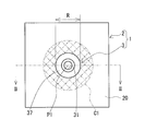
- FIG. 1 is a plan view showing a magnesium alloy member of the embodiment.
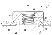
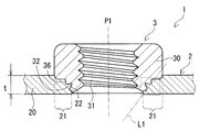
- FIG. 2A is an example of the magnesium alloy member of the embodiment shown in FIG. 1, and is a cross-sectional view taken along the II-II cutting line shown in FIG.
- FIG. 2B is another example of the magnesium alloy member of the embodiment shown in FIG. 1, and is a cross-sectional view taken along the II-II cutting line shown in FIG.
- FIG. 2C is a diagram for explaining the cross-sectional area of the groove portion of the caulking nut.
- FIG. 2D is a diagram illustrating a method of measuring the ratio of the total cross-sectional area of the gap to the cross-sectional area of the groove portion of the caulking nut.
- FIG. 3A is a process diagram for explaining the method for manufacturing the magnesium alloy member of the embodiment, and is a cross-sectional view showing a preparatory process.
- FIG. 3B is a process diagram for explaining the method for manufacturing the magnesium alloy member of the embodiment, and is a cross-sectional view showing the arrangement process.
- FIG. 3C is a process diagram for explaining the method for manufacturing the magnesium alloy member of the embodiment, and is a cross-sectional view showing the initial stage of the mounting process.
- FIG. 3D is a process diagram for explaining the method for manufacturing the magnesium alloy member of the embodiment, and is a cross-sectional view showing the latter stage of the mounting process.
- FIG. 3A is a process diagram for explaining the method for manufacturing the magnesium alloy member of the embodiment, and is a cross-sectional view showing a preparatory process.
- FIG. 3B is a process diagram for explaining the method for manufacturing the magnesium alloy member of the embodiment, and is a cross-sectional view showing the arrangement process.
- FIG. 3C is
- FIG. 3E is a process diagram illustrating a method for manufacturing the magnesium alloy member of the embodiment, and is a cross-sectional view showing a mold removing step.
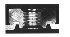
- FIG. 4 shows the sample No. of Test Example 1. It is a figure which shows the cross-sectional photograph which cut
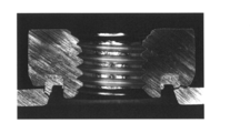
- FIG. 5 shows the sample No. of Test Example 1. It is a figure which shows the cross-sectional photograph which cut the magnesium alloy member of 101 in the plane including the shaft of the caulking nut.
- FIG. 6 shows the sample No. of Test Example 1.
- FIG. 7 shows the sample No. of Test Example 1. It is a figure which shows the cross-sectional photograph which cut the magnesium alloy member of 102 in the plane including the shaft of the caulking nut, and is the figure which enlarges and shows the region near the groove part of the caulking nut.
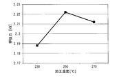
- FIG. 8 is a graph showing the relationship between the processing temperature and the idling torque in the sample having the pierced nut among the samples prepared in Test Example 1.
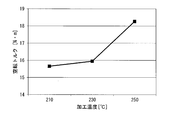
- FIG. 9 is a graph showing the relationship between the processing temperature and the punching force in the sample having the pierced nut among the samples prepared in Test Example 1.
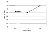
- FIG. 10 is a graph showing the relationship between the processing temperature and the idling torque in the sample having the clinching nut among the samples prepared in Test Example 1.
- FIG. 11 is a graph showing the relationship between the processing temperature and the punching force in the sample having the clinching nut among the samples prepared in Test Example 1.
- the caulking nut is a magnesium alloy member attached to a plate-shaped portion made of a magnesium alloy and has excellent fixing strength of the caulking nut.
- Magnesium alloys are generally inferior in plastic workability at room temperature. Therefore, when a commercially available caulking nut is attached to the magnesium alloy plate at room temperature, for example, 25 ° C., as in the case of the steel plate, the place where the caulking nut is attached and the place where the caulking nut is attached in the magnesium alloy plate and as shown in the test example described later. Cracks occur around it. Due to the cracks, the fixing strength of the caulking nut is low. Due to the low fixing strength, it is conceivable that the caulking nut will fall off from the magnesium alloy plate when the bolt is fastened to the caulking nut.
- Patent Document 2 discloses that by forming the grooves of the casting base and the nut into a specific shape as described above, the amount of plastic deformation of the casting base is reduced and the occurrence of cracks is suppressed. However, since the amount of plastic deformation of the casting base is small, the amount filled in the groove of the nut in the casting base is small. As a result, it is considered that the fixing strength between the casting base and the nut is low. In addition, both the casting base and the nut need to be molded into a specific shape. In this respect, this prior art is inferior in manufacturability of the magnesium alloy member with nut.
- one of the purposes of the present disclosure is to provide a magnesium alloy member having excellent fixing strength of the caulking nut.
- Another object of the present disclosure is to provide a method for manufacturing a magnesium alloy member to which a caulking nut can be firmly attached.
- the magnesium alloy member of the present disclosure is excellent in fixing strength of the caulking nut.
- a caulking nut can be firmly attached.
- the magnesium alloy member according to one aspect of the present disclosure is With a caulking nut With a base including a plate-shaped part, The base is made of magnesium alloy The caulking nut is attached to the plate-shaped portion and is attached to the plate-shaped portion.
- the idling torque of the caulking nut is 8.5 Nm or more.
- the magnesium alloy member according to one aspect of the present disclosure may be referred to as the first Mg alloy member.
- the plate-shaped part is unlikely to crack. Therefore, the caulking nut is prevented from falling off from the plate-shaped portion.
- Such a first Mg alloy member is excellent in fixing strength between the plate-shaped portion and the caulking nut. Further, since such a first Mg alloy member can secure a large tightening torque, a strong bolt fastening structure can be constructed.
- the magnesium alloy member according to another aspect of the present disclosure is With a caulking nut With a base including a plate-shaped part, The base is made of magnesium alloy The caulking nut is attached to the plate-shaped portion and is attached to the plate-shaped portion.
- the pushing force of the caulking nut is 0.8 kN or more.
- the magnesium alloy member according to another aspect of the present disclosure may be referred to as a second Mg alloy member.
- the second Mg alloy member even if a load along the axial direction of the caulking nut is applied to the plate-shaped portion when tightening a bolt to the caulking nut, cracks are unlikely to occur in the plate-shaped portion. Therefore, the caulking nut is prevented from falling off from the plate-shaped portion.
- Such a second Mg alloy member is excellent in fixing strength between the plate-shaped portion and the caulking nut. Further, such a second Mg alloy member is excellent in bolt fastening workability because the allowable range of the load along the axial direction is large when the bolt is fastened or the like.
- the first Mg alloy member of the present disclosure examples thereof include a form in which the pushing force of the caulking nut is 0.8 kN or more.
- the caulking nut has a tubular portion provided with a screw hole and a groove portion, and has a tubular portion.
- the groove portion is provided in the tubular portion so as to bite the region on the screw hole side of the plate-shaped portion.
- the plate-shaped portion includes a filling portion that enters the groove portion.
- the plate-shaped portion includes a portion that overlaps the crimping nut in a plan view from the axial direction of the caulking nut.
- the portion overlapping the caulking nut may be in a form having no crack.
- the above cracks may occur when installing the caulking nut. If there is no such crack, the above-mentioned crack does not develop and a large crack does not occur when the above-mentioned rotational force at the time of fastening or a load along the axial direction of the caulking nut is applied to the plate-shaped portion. Therefore, the above-mentioned form can more reliably prevent the caulking nut from falling off from the plate-shaped portion.
- Examples of the magnesium alloy include a form containing 7.2% by mass or more of Al.
- a magnesium alloy having an Al content of 7.2% by mass or more is excellent in strength, rigidity, and corrosion resistance as compared with a case where the Al content is less than 7.2% by mass. Therefore, the above form is excellent in strength, rigidity, and corrosion resistance.
- the nominal diameter of the caulking nut may be M4 or more and M12 or less specified in JIS B 1180: 2014.
- the above form is excellent in manufacturability because a commercially available caulking nut can be used.
- the method for manufacturing a magnesium alloy member according to one aspect of the present disclosure is as follows. A step of driving a caulking nut into the plate-shaped portion by a punch while the material having the plate-shaped portion is supported by a die is provided. The material is composed of a magnesium alloy. The step is performed in a state where the material, the die and the punch are heated to a warm region of the magnesium alloy.
- the method for producing a magnesium alloy member according to one aspect of the present disclosure may be referred to as the present production method.
- a caulking nut can be firmly attached to a material made of magnesium alloy.
- the reason for this is that the plastic workability of the material is enhanced by heating both the material and the die and punch, which are dies, to the warm region of the magnesium alloy.
- this manufacturing method it is not necessary to mold the material and the caulking nut into a special shape.
- a general magnesium alloy plate and a commercially available caulking nut can be used. In this respect, this manufacturing method can produce a magnesium alloy member having excellent fixing strength of the caulking nut with high productivity.
- Examples of the warm range include a form in which the temperature is 200 ° C. or higher and 280 ° C. or lower.
- step 10 As an example of the manufacturing method of the magnesium alloy member of the present disclosure, there is a form in which the caulking nut is heated to the warm region.
- the temperature of the material does not easily drop when the material comes into contact with the caulking nut. Therefore, the temperature of the material is appropriately maintained in the warm range of the magnesium alloy. Therefore, the above-mentioned form can enhance the plastic workability of the material.
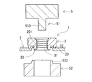
- FIG. 1 is a plan view of the magnesium alloy member 1 of the embodiment in the axial direction of the caulking nut 3.
- the axial direction of the caulking nut 3 corresponds to the vertical direction on the paper surface in FIG. 2A and 2B are cross-sectional views of the magnesium alloy member 1 of the embodiment cut along a plane including the shaft P1 of the caulking nut 3.
- the plane including the shaft P1 is a plane parallel to the shaft P1 and passes through the shaft P1 of the caulking nut 3.
- the magnesium alloy member 1 of the embodiment includes a base 2 and a caulking nut 3.
- the base 2 is made of a magnesium alloy.
- the base portion 2 includes a plate-shaped portion 20.
- the caulking nut 3 is attached to the plate-shaped portion 20 by locally biting the plate-shaped portion 20.
- the caulking nut 3 is firmly attached to the plate-shaped portion 20.
- the magnesium alloy constituting the base 2 contains an additive element, and the balance is composed of Mg (magnesium) and unavoidable impurities, and is an alloy containing the largest amount of Mg.
- the additive elements are, for example, Al (aluminum), Zn (zinc), Mn (manganese), Si (silicon), Be (berylium), Ca (calcium), Sr (strontium), Y (yttrium), Li (lithium). , Zr (zirconium), Ce (cerium), and one or more elements selected from the group consisting of rare earth elements excluding Y and Ce.
- magnesium alloys containing Al are excellent in mechanical properties such as strength and rigidity, and corrosion resistance.
- the Al content is, for example, 0.1% by mass or more and 12% by mass or less.
- a magnesium alloy containing 7.2% by mass or more of Al is excellent in strength, rigidity, and corrosion resistance as compared with the case where the Al content is less than 7.2% by mass. Therefore, the magnesium alloy member 1 including the base portion 2 made of a magnesium alloy containing 7.2% by mass or more of Al is excellent in strength, rigidity, and corrosion resistance.
- the magnesium alloy member 1 including the base portion 2 made of a magnesium alloy containing Al in the above range is excellent in manufacturability because the caulking nut 3 can be easily attached in the manufacturing process.
- each additive element other than Al is, for example, 0.01% by mass or more and 10% by mass or less, and further 0.1% by mass or more and 5% by mass or less.
- magnesium alloy an alloy having a known composition, for example, various alloys specified in ASTM standard can be used.
- examples of magnesium alloys containing Al include AZ alloys, AM alloys, AS alloys and the like.
- examples of the magnesium alloy containing Zn and Zr include ZK-based alloys.
- Examples of the AZ alloy containing 7.2% by mass or more of Al include AZ31, AZ61, and AZ91.
- the base 2 includes a plate-shaped portion 20. As shown in FIGS. 2A and 2B, the plate-shaped portion 20 includes a mounting portion 21 where the caulking nut 3 is mounted.
- the base 2 includes a portion where the two surfaces are provided substantially in parallel and the distance between the two surfaces is substantially the same. The above two surfaces correspond to the upper surface and the lower surface in FIGS. 2A and 2B. The above distance corresponds to the thickness of the base 2.
- the plate-shaped portion 20 has substantially the same thickness except for the mounting portion 21. Details of the mounting location 21 will be described later.
- the base portion 2 may have a form in which substantially the entire base portion 2 is a plate-shaped portion 20. This form has substantially the same thickness over the entire base 2 except for the mounting location 21 of the caulking nut 3.
- the base 2 is a flat plate material, that is, a magnesium alloy plate.
- 2A and 2B illustrate the case where the base 2 is a flat plate material.
- the base portion 2 is a three-dimensional object having a bent portion or a curved portion at least a part of the base portion 2. Examples of the three-dimensional object include a box, a cylinder, and the like.
- the base portion 2 may include a portion other than the plate-shaped portion 20.
- the base portion 2 may have at least one of a locally thick portion, a locally thin portion, and a through hole in addition to the plate-shaped portion 20.
- Locally thick portions include, for example, protrusions.
- Locally thin portions include, for example, grooves and steps.
- a typical example of a magnesium alloy plate is one manufactured through a rolling process.
- the rolled magnesium alloy plate has excellent plastic workability, so that the caulking nut 3 can be attached well in the manufacturing process, has excellent mechanical properties such as strength, and easily has a uniform thickness.
- the magnesium alloy plate may be a cast material formed by a casting method such as a die casting method.
- Examples of the above-mentioned three-dimensional object include a molded body obtained by plastically working a magnesium alloy plate to form a predetermined shape. Examples of plastic working include press molding and the like.
- examples of the three-dimensional object include a cast material formed by a casting method such as a die casting method. The cast material is easy to manufacture even if it has a complicated three-dimensional shape.
- the attachment portion 21 of the caulking nut 3 is a portion of the plate-shaped portion 20 that comes into contact with the caulking nut 3 and a portion in the vicinity thereof.
- the mounting portion 21 is a portion of the plate-shaped portion 20 that is overlapped with the caulking nut 3 when the magnesium alloy member 1 is viewed in a plan view from the axial direction of the caulking nut 3. Therefore, the mounting portion 21 is provided in an annular shape along the circumferential direction of the caulking nut 3.
- the attachment portion 21 of the caulking nut 3 includes a portion where the plate-shaped portion 20 is plastically deformed by being bitten into the caulking nut 3.
- This plastically deformed portion is provided in the region of the plate-shaped portion 20 on the screw hole 31 side of the caulking nut 3. Further, at least a part of the plastically deformed portion has a shape corresponding to the outer shape of the groove portion 32 of the caulking nut 3 by entering the groove portion 32. That is, the plate-shaped portion 20 includes a filling portion 22 that enters the groove portion 32. Further, the plastically deformed portion may include a portion of the plate-shaped portion 20 that is thinner than the thickness t of a portion other than the attachment portion 21. Details of the screw hole 31 and the groove 32 of the caulking nut 3 will be described later.
- the thickness t of the portion of the plate-shaped portion 20 other than the attachment portion 21 of the caulking nut 3 is substantially equal to the thickness t 200 of the plate-shaped portion 20 of the material 200 before the caulking nut 3 is attached.
- the thickness t or the thickness t 200 may be appropriately selected within a range in which the caulking nut 3 can be attached.
- the thickness t is 0.1 mm or more and 5.0 mm or less, and further 0.3 mm or more and 4.0 mm or less.
- the magnesium alloy member 1 is excellent in manufacturability in that a commercially available caulking nut 3 can be used.
- the thickness t may be selected according to the type and size of the caulking nut 3. Examples of the size of the caulking nut 3 include a nominal diameter specified in JIS B 1180: 2014.
- the above-mentioned thickness t is an average value measured in a region near the mounting portion 21 of the caulking nut 3 in the plate-shaped portion 20.
- the neighborhood region is the following annular region.
- a circle C1 having a axis P1 of the caulking nut 3 as a center and an outer diameter R of the caulking nut 3 as a radius is taken.
- the annular region is a region obtained by removing the outer peripheral circle of the caulking nut 3 from the circle C1.
- the outer circle of the caulking nut 3 corresponds to a circle having an outer diameter R.
- three or more measurement points are taken at equal intervals in the circumferential direction, and the thickness of each measurement point is measured.
- the thickness t is a value obtained by averaging the thicknesses of three or more measurement points.
- FIG. 1 virtually shows the annular region by cross-hatching the alternate long and short dash line to the annular region.
- the caulking nut 3 is a nut that is attached by being press-fitted into a metal plate.
- the caulking nut 3 includes a tubular portion 30 provided with a screw hole 31 and a groove portion 32, as shown in FIGS. 2A, 2B, and 3A described later.
- the screw hole 31 constitutes a female screw.
- a bolt (not shown) is screwed into the screw hole 31.
- the groove portion 32 is provided in the tubular portion 30 so as to bite the region on the screw hole 31 side of the plate-shaped portion 20 described above. Further, the groove portion 32 is provided in an annular shape. Typically, the groove 32 opens in the end face 35 of the tubular portion 30 as shown in FIG. 2A.
- the groove portion 32 opens on the outer peripheral surface 36 as shown in FIG. 2B.
- the opening of the groove portion 32 is arranged so as to face the region on the screw hole 31 side of the plate-shaped portion 20.
- the groove portion 32 is filled with the metal constituting the metal plate to which the caulking nut 3 is attached, here, the magnesium alloy constituting the plate-shaped portion 20 in a plastically deformed state.
- the plastically deformed portion of the plate-shaped portion 20 constitutes the above-mentioned filling portion 22.
- Typical examples of the caulking nut 3 include piercing nuts and clinching nuts.
- piercing nut and the clinching nut commercially available products and other known ones can be used.
- FIG. 2A illustrates a pierce nut as the caulking nut 3.
- the groove portion 32 of the pierce nut is typically an annular groove that opens to the end face 35 arranged on the plate-shaped portion 20 side of the two end faces of the tubular portion 30.
- the tubular portion 30 of the pierce nut has a locally thin portion on the end face 35 side.
- the locally thin portion will be referred to as a thin cylinder portion 33.
- the end face 35 side corresponds to the lower side in FIG. 2A.
- the thin cylinder portion 33 protrudes from the end face 35.
- the thin cylinder portion 33 is used to provide a through hole in the metal plate when the pierce nut is attached to the metal plate. A part of the outer peripheral surface of the thin cylinder portion 33 is supported by the inner peripheral surface forming the through hole. As a result, the thin cylinder portion 33 is supported by the plate-shaped portion 20 with the through hole inserted.
- the groove portion 32 is filled with a metal plate, in which a region of the plate-shaped portion 20 in the vicinity of the through hole is plastically deformed and filled. It is also preferable to refer to FIG. 3A described later for the groove portion 32 and FIGS. 3C and 3D described later for the thin cylinder portion 33.
- FIG. 2B illustrates a clinching nut as the caulking nut 3.
- a part of the tubular portion 30 of the clinching nut is in a state of being inserted into a metal plate. Therefore, a part of the tubular portion 30 is covered with the metal constituting the metal plate over the entire circumference of the tubular portion 30 in the circumferential direction.
- the groove portion 32 of the clinching nut is typically an annular groove that opens on the outer peripheral surface 36 of the tubular portion 30.
- the groove portion 32 is filled with a metal plate, in which a region in the plate-shaped portion 20 in the vicinity of the above-mentioned pilot hole is plastically deformed and filled.
- the nominal diameter of the caulking nut 3 can be appropriately selected.
- the nominal diameter may be M4 or more and M12 or less specified in JIS B 1180: 2014.
- the nominal diameter may be M5 or more and M10 or less.
- the magnesium alloy member 1 provided with the caulking nut 3 having the nominal diameter of M5 or more and M10 or less can be used for a housing, a structural member, or the like.
- the nominal diameter of the caulking nut 3 is the nominal diameter of the bolt screwed into the screw hole 31.
- the number of caulking nuts 3 provided in the magnesium alloy member 1 does not matter.
- the magnesium alloy member 1 shown in FIG. 1 includes one caulking nut 3, but may include a plurality of caulking nuts 3.
- the mounting position of the caulking nut 3 provided on the magnesium alloy member 1 can be appropriately selected depending on the application and the like.
- the mounting position in FIG. 1 is an example.
- a part of the magnesium alloy constituting the base portion 2 is filled in the groove portion 32 provided in the caulking nut 3.
- the filling amount of the magnesium alloy in the groove 32 is large. That is, there is little gap provided between the filling portion 22 filled in the groove portion 32 and the inner peripheral surface of the groove portion 32. Further, it can be said that the groove portion 32 is filled with the filling portion 22. Quantitatively, for example, the following porosity is 2.5% or less.
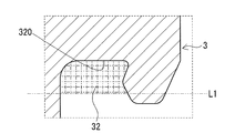
- ⁇ Porosity> A cross section of the magnesium alloy member 1 cut along a plane including the shaft P1 of the caulking nut 3 is taken. In the cross section, as follows, obtaining the cross-sectional area S 3 of the groove 32, and the total sectional area S of the gap 9.
- the porosity (%) is the ratio of the total cross-sectional area S of the gap 9 to the cross-sectional area S 3 of the groove 32.
- the porosity (%) is calculated by (S / S 3 ) ⁇ 100.
- the cross-sectional area S 3 of the groove 32 the following linear L1, which is the area of the region surrounded by the inner peripheral surface 320 of the groove 32.
- the straight line L1 is a plane orthogonal to the axis P1 of the caulking nut 3 and is taken so as to be in contact with the surface of the filling portion 22. That is, the straight line L1 is taken so as to close the opening of the groove 32.
- the surface of the filling portion 22 is typically formed by the pushing portion 522 of the die 52 in the manufacturing process. For the push-in portion 522, refer to FIG. 3D described later.
- FIGS. 2C and 2D are cross-sectional views showing an enlarged region of the groove portion 32 and its vicinity when the caulking nut 3 is a pierce nut.
- the above-mentioned area shown in FIGS. 2C and 2D corresponds to the area surrounded by the broken line rectangle in FIG. 2A.
- a region surrounded by the inner peripheral surface 320 and the straight line L1 of the groove 32, the cross-sectional area S 3 of the area of the region lattice hatching of the two-dot chain line is given the groove 32.
- FIG. 2D illustrates a case where the groove portion 32 has a gap 9.
- the gap 9 is provided between the filling portion 22 filled in the groove portion 32 and the inner peripheral surface 320 of the groove portion 32 in the region surrounded by the straight line L1 and the inner peripheral surface 320 of the groove portion 32.
- the gap 9 is a region with a grid-like hatching of fine solid lines.
- the total area of the hatched area is the total cross-sectional area S of the gap 9.
- the total cross-sectional area S of the gap 9 can be obtained by subtracting the cross-sectional area S 22 of the filling portion 22 occupying the area surrounded by the inner peripheral surface 320 of the groove portion 32 and the straight line L1 from the cross-sectional area S 3 of the groove portion 32. Good. That is, the total cross-sectional area S of the gap 9 may be obtained by (S 3- S 22 ).
- the groove portion 32 opens in a direction substantially orthogonal to the axis P1 of the caulking nut 3 and the opening of the groove portion 32 is embedded in the base portion 2
- the straight line L1 is taken so as to close the opening of the groove 32.
- the straight line L1 is a straight line passing through the virtual surface forming the opening of the groove portion 32.
- the porosity is 2.5% or less, that is, if the ratio S / S 3 is 0.025 or less, it can be said that the groove portion 32 has substantially no gap 9 and the filling portion 22 is filled.
- the amount of plastic deformation of the plate-shaped portion 20 is large in the manufacturing process. Since the amount of plastic deformation is large, a large contact area between the plate-shaped portion 20 and the caulking nut 3 is secured. As a result, a strong meshing structure can be constructed between the plate-shaped portion 20 and the caulking nut 3. Therefore, the magnesium alloy member 1 is excellent in the fixing strength of the caulking nut 3.
- the porosity is preferably 2.0% or less, more preferably 1.5% or less, and 1.0% or less. It is more preferable that the porosity is 0%, that is, there is substantially no gap 9. 2A and 2B show a case where the porosity is 0%.
- the mounting portion 21 of the caulking nut 3 does not have a crack.
- the magnesium alloy member 1 has no cracks in the vicinity of the groove 32 in the plate-shaped portion 20, that is, inside and outside the groove 32.
- the cracks may occur when the caulking nut 3 is attached to the material 200 during the manufacturing process. If there are no cracks in the mounting portion 21 of the caulking nut 3, even if a rotational force for tightening the bolt, a load along the axial direction of the caulking nut 3, or the like is applied to the plate-shaped portion 20 including the mounting portion 21, the plate Large cracks are unlikely to occur in the shape portion 20. The reason for this is that the phenomenon that small cracks propagate and become large cracks due to the above-mentioned rotational force and load does not substantially occur. Since such a magnesium alloy member 1 can effectively prevent the caulking nut 3 from falling off from the plate-shaped portion 20 when the bolt is fastened or the like, it can be said that the caulking nut 3 is excellent in fixing strength.
- the magnesium alloy member 1 of the embodiment for example, the idling torque of the caulking nut 3 satisfies 8.5 Nm or more.
- the idling torque is 8.5 Nm or more, even if the rotational force when tightening the bolt to the caulking nut 3 is applied to the plate-shaped portion 20 including the mounting portion 21 of the caulking nut 3, the plate-shaped portion 20 is cracked. Is unlikely to occur. Therefore, the caulking nut 3 is prevented from falling off from the plate-shaped portion 20. It can be said that such a magnesium alloy member 1 is excellent in fixing strength of the caulking nut 3.
- the idling torque is 10 N ⁇ m or more, and further 15 N ⁇ m or more. If the idling torque is 20 N ⁇ m or more, and further 25 N ⁇ m or more, although it depends on the thickness t of the plate-shaped portion 20 and the size of the caulking nut 3, for example, the nominal diameter specified in JIS B 1180: 2014. , The above fixing strength is higher.
- the larger the idling torque the larger the tightening torque allowed when tightening the bolt can be secured. Since such a magnesium alloy member 1 can firmly tighten bolts, a strong bolt fastening structure can be constructed. The upper limit of the idling torque is not particularly set.
- the magnesium alloy member 1 having the above-mentioned porosity of 2.5% or less typically has an idling torque of 8.5 Nm or more.
- the magnesium alloy member 1 having no crack in the mounting portion 21 of the caulking nut 3 described above typically has an idling torque of 8.5 Nm or more.
- the idling torque is measured as follows.
- the magnesium alloy member 1 is arranged on the pedestal so that the caulking nut 3 faces upward, and the plate-shaped portion 20 is fixed.
- the caulking nut 3 is gripped with a jig.
- This jig is rotated around the axis of the caulking nut 3. That is, a rotational force that twists the caulking nut 3 is applied to the caulking nut 3.
- the rotational force is increased, and the jig is rotated until the caulking nut 3 is removed from the plate-shaped portion 20.
- the idling torque is the maximum rotational force when the caulking nut 3 is removed from the plate-shaped portion 20.
- a commercially available tool for measuring torque such as a torque wrench, can be used.
- the pushing force of the caulking nut 3 satisfies 0.8 kN or more.
- the pushing force is 1.00 kN or more, 1.10 kN or more, and 1.15 kN or more.
- the punching force should be 1.2 kN or more, and further 1.5 kN or more.
- the fixing strength is higher.
- the larger the pushing force the larger the allowable range of the load along the axial direction described above can be secured when the bolt is fastened.
- Such a magnesium alloy member 1 is excellent in bolt fastening workability. There is no particular upper limit on the pushing force.
- the magnesium alloy member 1 having the above-mentioned porosity of 2.5% or less typically has a punching force of 0.8 kN or more. The smaller the porosity, the higher the pushing force.
- the magnesium alloy member 1 having no crack in the mounting portion 21 of the caulking nut 3 described above typically has a pushing force of 0.8 kN or more.
- the pushing force is measured as follows.
- the magnesium alloy member 1 shown in FIGS. 2A and 2B is turned upside down, and the plate-shaped portion 20 is arranged on the pedestal so that the caulking nut 3 is arranged downward.
- the pedestal is provided with a through hole larger than the outer diameter R of the caulking nut 3.
- the caulking nut 3 is inserted into the through hole.
- the area around the caulking nut 3 in the plate-shaped portion 20 is supported by the area around the through hole in the pedestal. With the plate-shaped portion 20 supported by the pedestal, a load is applied to the caulking nut 3 along the shaft P1 direction by a jig.
- the jig is arranged so that the caulking nut 3 is pressed but the plate-shaped portion 20 is not pressed.
- a bolt may be screwed into the caulking nut 3 and the jig may press the head of the bolt. In this case, the load is easily transmitted to the caulking nut 3.
- the jig may press the thin cylinder portion 33.
- the pressing surface of the jig is brought into direct contact with the end surface of the thin cylinder portion 33.
- the load is increased and the load is applied until the caulking nut 3 comes off from the plate-shaped portion 20.
- the pushing force is the maximum load when the caulking nut 3 comes off.
- a commercially available clinch meter can be used for the measurement of the pressing force.
- the above-mentioned idling torque satisfies 8.5 Nm or more and the above-mentioned punching force satisfies 0.8 kN or more.
- Such a magnesium alloy member 1 has a plate shape including a mounting portion 21 of the caulking nut 3 in which a rotational force at the time of fastening the bolt and a load along the axial direction of the caulking nut 3 are applied when tightening the bolt to the caulking nut 3. Even if it is added to the portion 20, cracks are less likely to occur in the plate-shaped portion 20. Therefore, the caulking nut 3 is effectively prevented from falling off from the plate-shaped portion 20. It can be said that such a magnesium alloy member 1 is superior to the fixing strength of the caulking nut 3.
- the magnesium alloy member 1 of the embodiment is excellent in fixing strength between the caulking nut 3 attached to the plate-shaped portion 20 and the plate-shaped portion 20. This effect will be specifically described in a test example described later.
- the magnesium alloy member 1 of the above-described embodiment may be manufactured by, for example, a method of manufacturing the magnesium alloy member of the embodiment including the following mounting steps, that is, the present manufacturing method.
- ⁇ Mounting Step> With the material 200 having the plate-shaped portion 20 supported by the die 52, the caulking nut 3 is driven into the plate-shaped portion 20 by the punch 51 (see FIGS. 3C and 3D).
- the material 200 is made of a magnesium alloy.
- the mounting step is performed in a state where the material 200 having the plate-shaped portion 20 and the die 52 and the punch 51 are heated to the warm region of the magnesium alloy.
- the warm range of the magnesium alloy is a temperature above room temperature and below the recrystallization temperature of the magnesium alloy.
- the plastic workability of the material 200, particularly the plate-shaped portion 20 is improved by setting the processing temperature when the caulking nut 3 is attached to the plate-shaped portion 20 to the warm range of the magnesium alloy instead of room temperature.
- the plastic workability of the plate-shaped portion 20 can be effectively enhanced by heating both the material 200 and the die 52 and the punch 51 which are the dies 5 to the warm region of the magnesium alloy.
- the room temperature here is 20 ° C. ⁇ 15 ° C., typically 25 ° C.
- This manufacturing method typically includes the following preparation step, placement step, the above-mentioned mounting step, and mold removal step. Refer to FIGS. 3C and 3D for the mounting process.
- ⁇ Preparation Step> The above-mentioned material 200, a caulking nut 3, and a mold 5 are prepared.
- the mold 5 includes a punch 51 and a die 52. Refer to FIG. 3A for the preparation step.
- ⁇ Arrangement process> The die 52, the material 200, the caulking nut 3, and the punch 51 are arranged in this order from the bottom.
- the plate-shaped portion 20 of the material 200 is supported by the die 52.
- the caulking nut 3 is arranged at a predetermined position of the plate-shaped portion 20. When the plate-shaped portion 20 has a pilot hole, the caulking nut 3 is arranged at the position where the pilot hole is formed. Refer to FIG. 3B for the arrangement process.
- ⁇ Mold Removal Step> After attaching the caulking nut 3 to the plate-shaped portion 20 of the material 200, the mold 5 is removed from the magnesium alloy member 1. Refer to FIG. 3E for the mold removing step.
- the material 200 may include a plate-shaped portion 20.
- the material 200 is provided with a pilot hole according to the size of the caulking nut 3, if necessary. Preliminary holes (not shown) may be formed by performing appropriate machining such as punching.
- FIG. 3A illustrates a case where the pilot hole is not provided.
- caulking nut 3 For the caulking nut 3, it is advisable to refer to the above-mentioned (caulking nut) section.
- the mold 5 of this example includes a punch 51, a die 52, and a heating mechanism (not shown).
- the punch 51 of this example includes a shaft portion 510 and a main body 512.
- the die 52 of this example includes a main body 520 provided with a through hole 524 and a pushing portion 522.
- the heating mechanism may include a heating unit such as a heater and a control panel or the like of the heating unit.
- the heating unit may be built in the main body 512,520 or the like.
- the shaft portion 510 is inserted into the screw hole 31 of the caulking nut 3 and is used for positioning the main body 512 with respect to the guide and the caulking nut 3.
- the shaft portion 510 typically includes a columnar body such as a round bar having an inner diameter smaller than the minimum inner diameter of the screw hole 31.
- the length of the shaft portion 510 is such that the end face of the shaft portion 510 does not protrude from the opening of the screw hole 31 when the shaft portion 510 is inserted into the screw hole 31, or the opening. It is almost flush with the virtual surface created by.
- the main body 512 is a member that presses the caulking nut 3 against the plate-shaped portion 20.
- the main body 512 is typically a columnar body such as a columnar body having an outer diameter larger than the outer diameter of the shaft portion 510.
- the shaft portion 510 is erected on the end surface 511 arranged on the caulking nut 3 side of the main body 512.
- the end face 511 is arranged in contact with the caulking nut 3 as shown in FIGS. 3C and 3D.
- the end face 511 is used as a surface for pressing the end face 37 of the caulking nut 3.
- the main body 520 mainly supports the plate-shaped portion 20 of the material 200.
- the main body 520 of this example is a tubular body provided with a through hole 524 in the central portion.
- the through hole 524 is used to support the outer peripheral surface of the thin cylinder portion 33 of the caulking nut 3 as shown in FIG. 3C, and to discharge the chips 202 as shown in FIG. 3D.
- the chip 202 is generated when a part of the plate-shaped portion 20 is punched out by the thin cylinder portion 33 to form a through hole 201 in the plate-shaped portion 20.
- the main body 520 has an annular protrusion on the end surface on the side where the plate-shaped portion 20 of the material 200 is arranged, and on the upper surface in FIG. 3A and the like.
- An annular protrusion is provided along the periphery of the through hole 524.
- This annular protrusion is the push-in portion 522.
- the pushing portion 522 is used to push the region of the plate-shaped portion 20 in the vicinity of the above-mentioned through hole 201 into the groove portion 32 of the caulking nut 3.
- the shape of the push-in portion 522 is a truncated cone shape having a part of the through hole 524.
- the plate-shaped portion 20 of the material 200 is arranged on the pushing portion 522 of the die 52. Further, with the shaft portion 510 of the punch 51 inserted into the screw hole 31 of the caulking nut 3, the punch 51 and the caulking nut 3 are arranged in the plate-shaped portion 20. In this case, the through hole 524 of the die 52, the screw hole 31 of the caulking nut 3, and the shaft portion 510 of the punch 51 are likely to be arranged coaxially. As a result, the caulking nut 3 is attached to an appropriate position of the plate-shaped portion 20.
- the plate-shaped portion 20 of the material 200 is provided with a pilot hole in advance
- the plate-shaped portion 20 is arranged on the die 52 so that the through hole 524 of the die 52 and the pilot hole are coaxial with each other.
- the caulking nut 3 is arranged in the plate-shaped portion 20 by fitting a part of the caulking nut 3 into the prepared hole of the plate-shaped portion 20.
- the caulking nut 3 is driven into the plate-shaped portion 20 of the material 200 by the mold 5.
- the end face 37 of the caulking nut 3 is pressed against the plate-shaped portion 20 side by the end face 511 of the main body 512.
- the thin cylinder portion 33 comes into contact with a part of the plate-shaped portion 20 to press the plate-shaped portion 20.
- the punch 51 moves, the thin cylinder portion 33 enters the through hole 524 of the main body 520, and as shown in FIG. 3C, the plate-shaped portion 20 is provided with the through hole 201.
- the end face 35 of the caulking nut 3 then comes into contact with the plate-shaped portion 20. In this state, the caulking nut 3 is sandwiched between the punch 51 and the die 52 via the plate-shaped portion 20.
- the groove 32 of the caulking nut 3 approaches so as to cover the pushing portion 522 of the die 52.
- the region in the vicinity of the through hole 201 in the plate-shaped portion 20 is sandwiched between the end face 35 and the region in the vicinity thereof and the pushing portion 522.
- the region of the plate-shaped portion 20 is pushed into the pushing portion 522 and is filled in the groove portion 32. That is, the region of the plate-shaped portion 20 is narrowed down by the mold 5 and press-fitted into the caulking nut 3.
- the chips 202 generated by the formation of the through hole 201 are pushed by the thin cylinder portion 33 and the shaft portion 510, and fall from the through hole 524 of the die 52.
- the caulking nut 3 is also heated to the warm range of the magnesium alloy.
- the reason for this is that it is possible to prevent the temperature of the plate-shaped portion 20 of the material 200 in contact with the caulking nut 3 from dropping. That is, the temperature of the plate-shaped portion 20 is appropriately maintained in the warm region. As a result, the plate-shaped portion 20 can be satisfactorily plastically deformed.
- the processing temperature that is, the heating temperature of the material 200 and the mold 5, preferably the caulking nut 3, is selected within a temperature range equal to or lower than the recrystallization temperature of the magnesium alloy constituting the material 200.
- the heating temperature in the warm range of the magnesium alloy is 200 ° C. or higher and 280 ° C. or lower.
- the heating temperature is 200 ° C. or higher, the plastic workability of the material 200 is enhanced. That is, a large amount of plastic deformation is secured in the plate-shaped portion 20 of the material 200. As a result, the plate-shaped portion 20 and the caulking nut 3 are firmly engaged with each other, and the caulking nut 3 is firmly attached to the plate-shaped portion 20.
- the higher the heating temperature the higher the plastic workability of the plate-shaped portion 20 tends to be.
- the heating temperature may be, for example, 210 ° C. or higher, 220 ° C. or higher, 230 ° C. or higher, or 240 ° C. or higher.
- the heating temperature is 280 ° C or less, the material 200 is unlikely to be burned.
- the heating temperature may be, for example, 275 ° C. or lower, and further 270 ° C. or lower.
- the heating temperature is, for example, 210 ° C. or higher and 275 ° C. or lower, and further 220 ° C. or higher and 270 ° C. or lower, the fixing strength of the caulking nut 3 tends to be higher.
- the fixing strength of the caulking nut 3 tends to be higher.
- the heating temperature is preferably adjusted according to the thickness t 200 of the plate-shaped portion 20, the composition of the magnesium alloy constituting the plate-shaped portion 20, the shape and size of the caulking nut 3.
- JIS B 1180 in the caulking nut 3 on the nominal diameter defined is relatively large in 2014, if the thickness t 200 is relatively thick, the heating temperature may be at higher temperatures.
- the thickness t 200 is 1.5mm or more, if it is more 2.0mm or more, the heating temperature is, for example 230 ° C. or higher, and a higher 240 ° C..
- the temperature of at least one of the material 200, the mold 5, and the caulking nut 3 may be different, or the temperatures of all three may be substantially the same. Good. If the temperatures of the three are the same, temperature control is easy. Further, the temperature of the punch 51 and the temperature of the die 52 may be different or substantially the same. When the heating temperature is different, the temperature difference may be 30 ° C. or lower, further 25 ° C. or lower.
- the caulking nut 3 is easy to use if it is heated and held in a constant temperature bath, for example.
- the heating temperature of the caulking nut 3 is higher than the temperature of the material 200. It may be expensive.
- At least one of the material 200 and the mold 5, preferably both, may be preheated to a warm region of the magnesium alloy.
- both the mold 5 and the material 200 are preheated as compared with the case where the mold 5 and the material 200 are heated in the warm region by the heating mechanism described above.
- the installation work time can be easily shortened.
- the temperature of the material 200 tends to be uniform. Therefore, the material 200, particularly the plate-shaped portion 20, is satisfactorily plastically deformed. In these respects, the above-mentioned form of preheating can produce the magnesium alloy member 1 with high productivity.
- a magnesium alloy member 1 in which the caulking nut 3 is firmly attached to the plate-shaped portion 20 can be obtained.
- a magnesium alloy member 1 satisfying at least one of the idling torque of the caulking nut 3 being 8.5 Nm or more and the pushing force of the caulking nut 3 being 0.8 kN or more can be obtained.
- the region of the plate-shaped portion 20 in the vicinity of the above-mentioned through hole 201 includes a region on the screw hole 31 side of the caulking nut 3 and a filling portion 22 that has entered the groove portion 32.
- the caulking nut 3 is firmly attached to the plate-shaped portion 20. This effect will be specifically described in the following test examples.
- a magnesium alloy plate having a composition equivalent to that of an AZ91 alloy was prepared.
- the composition is Mg-8.7% by mass Al-0.65% by mass Zn.
- This magnesium alloy plate was manufactured by a known method including a rolling step.
- the thickness of the prepared magnesium alloy plate is 1.3 mm to 2.0 mm.
- the thickness of the magnesium alloy plate is referred to as a plate thickness.
- a caulking nut As a caulking nut, a commercially available piercing nut and a commercially available clinching nut were prepared.
- the nominal diameter of the pierce nut is M10.
- the nominal diameter of the clinching nut is M10.
- the nominal diameter is a value standardized in JIS B 1180: 2014.
- a known mold equipped with a punch and a die was used. By attaching commercially available heaters to the punch and die, respectively, the punch and die can be heated.
- the plate with nuts 101 was produced by using a magnesium alloy plate having one plate thickness selected from the group consisting of 1.3 mm, 1.4 mm, and 1.5 mm and the above-mentioned pierced nut.
- the plate thickness (mm) of each sample is shown in Table 1.
- the processing temperature at which the pierce nut was attached to the magnesium alloy plate was set to the warm range of the magnesium alloy. Specifically, the magnesium alloy plate, the pierce nut, and both the punch and the die are heated to a temperature selected from the range of 210 ° C. or higher and 270 ° C. or lower. The pierce nut was attached to the magnesium alloy plate by driving the pierce nut at the above temperature into the magnesium alloy plate with a punch at the above temperature while the magnesium alloy plate at the above temperature was supported by the die at the above temperature.
- the heating temperature of the magnesium alloy plate was 210 ° C., and the heating temperature of the pierce nut and the heating temperature of the punch and die were 250 ° C.
- the heating temperature of the magnesium alloy plate was 230 ° C., and the heating temperature of the pierce nut and the heating temperature of the punch and die were 250 ° C.
- Sample No. 1 to No. In No. 5 the heating temperature (° C.) of the magnesium alloy plate, the pierce nut, and the mold was set to the processing temperature (° C.) shown in Table 1.
- the magnesium alloy plate, the pierce nut, and the die were heated to 250 ° C.
- the punch temperature was set to room temperature
- the pierce nut was attached to the magnesium alloy plate. That is, a part of the mold, here the punch, is not heated to the warm region of the magnesium alloy.
- the room temperature here is 25 ° C.
- the plate with nuts of 102 was produced by using a magnesium alloy plate having a plate thickness of 1.4 mm or 2.0 mm and the above-mentioned clinching nut.
- Table 2 shows the plate thickness (mm) of each sample.
- the processing temperature at which the clinching nut was attached to the magnesium alloy plate was set to the warm range of the magnesium alloy. Specifically, the magnesium alloy plate, the clinching nut, and both the punch and the die are heated to a temperature selected from the range of 210 ° C. or higher and 250 ° C. or lower. The clinching nut was attached to the magnesium alloy plate by driving the clinching nut at the above temperature into the magnesium alloy plate with a punch at the above temperature while the magnesium alloy plate at the above temperature was supported by the die at the above temperature. .. Sample No. 22-No. In No. 24, the heating temperature (° C.) of the magnesium alloy plate, the clinching nut, and the mold was set to the processing temperature (° C.) shown in Table 2.
- Sample No. In 102 the clinching nut was attached to the magnesium alloy plate with the temperatures of the magnesium alloy plate, the clinching nut, and the mold set to room temperature. That is, none of the above three is heated to the warm region of the magnesium alloy.
- the room temperature here is 25 ° C.
- the idling torque is measured as described above. Briefly, the nut-attached plate is placed on the pedestal so that the caulking nut is placed facing up. Grasp the caulking nut with a jig and rotate the caulking nut around its axis. Increase the rotational force until the caulking nut comes off the magnesium alloy plate. The idling torque is the maximum rotational force when the caulking nut is removed from the magnesium alloy plate.
- the idling torque was measured using a commercially available torque wrench. Further, here, 10 samples were prepared for each sample. The idling torques of 10 samples were measured, and the averaged values are shown in Tables 1 and 2 as the idling torques of each sample.
- the pushing force is measured as described above. Briefly, the nut-attached plate is placed on the pedestal so that the caulking nut is placed facing down. A jig is brought into contact with the end face of the caulking nut, and a load is applied along the axial direction of the caulking nut. Increase the load until the caulking nut comes off the magnesium alloy plate. The pushing force is the maximum load when the caulking nut comes off.
- the pushing force was measured using a commercially available clinch meter. Further, here, 10 samples were prepared for each sample. The punching force of 10 samples was measured, and the averaged values are shown in Tables 1 and 2 as the punching force of each sample.
- Sample No. 1 to No. 7, No. 21-No. All of the 24 nut-attached plates have an idling torque of 8.5 Nm or more.
- sample No. 1 to No. 7, No. 21-No. All of the 24 nut-attached plates have a pushing force of 0.8 kN or more.
- sample No. 1 to No. 7, No. 21-No. 24 is called a specific sample group.
- the idling torque of the specific sample group is 10 N ⁇ m or more and 12 N ⁇ m or more.
- the punching force is 1.0 kN or more. Therefore, in many of the specific sample groups, the caulking nut is firmly fixed by the magnesium alloy plate, and it can be said that the caulking nut is superior in fixing strength.
- the specific sample group equipped with the piercing nut has higher idling torque and pushing force than the specific sample group equipped with the clinching nut.
- the punching force is 1.5 kN or more, further 1.9 kN or more, and most samples are 2.0 kN or more.
- sample No. 101, No. All of the 102 nut-attached plates have an idling torque of 8.3 Nm or less and a pushing force of less than 0.1 kN.
- the reason for the difference in the fixing strength of the caulking nut is that, as shown in FIGS. 4 to 7, the properties of the nut-attached plates that come into contact with the caulking nuts in the magnesium alloy plate, that is, the caulking nut mounting locations, are different. Can be considered.
- the sample No. which is a specific sample group. 2, No. In No. 24, the plate with nut does not have a crack at the mounting location of the caulking nut.
- the contact area between the magnesium alloy plate and the caulking nut is large, and it can be said that they are in close contact with each other.
- the sample No. 101, No. In 102 a crack is generated at the mounting location of the caulking nut.
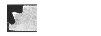
- Sample No. In 101 cracks are formed so as to divide the front and back surfaces of the magnesium alloy plate.
- sample No. In 101 due to this crack, the end face of the caulking nut is not in contact with the magnesium alloy plate, and a large gap is formed between the end face and the magnesium alloy plate.
- Sample No. In 102 the filling portion to be filled in the groove portion of the caulking nut in the magnesium alloy plate is divided into a plurality of parts by the crack, and a large gap 9 is formed between the groove portion and the filling portion.
- Porosity is the ratio of the total cross-sectional area of the gap to the cross-sectional area of the groove of the caulking nut.
- the total cross-sectional area of the gap is the gap provided between the filling portion filled in the groove portion of the caulking nut and the inner peripheral surface of the groove portion in the region surrounded by the straight line L1 and the inner peripheral surface of the groove portion as described above. It is the sum of the cross-sectional areas of.
- the porosity of the specific sample group is 0%. That is, in the specific sample group, it can be said that a part of the magnesium alloy plate is filled in the groove of the caulking nut with substantially no gap.
- sample No. The porosity of 102 is 30% or more, which is very large.
- Sample No. The porosity of 101 is 2.7%.
- the idling torque is 25 N ⁇ m or more and the pushing force is 2.18 kN or more, both of which are high. Therefore, according to the tendency of the graphs of FIGS. 8 and 9, in the range of 200 ° C. or higher and 280 ° C. or lower including the above temperature range, the magnesium alloy member having an idling torque of 8.5 Nm or higher and a punching force of 0. It is considered that a magnesium alloy member having a value of .8 kN or more can be obtained more reliably.
- a magnesium alloy member in which a caulking nut is attached to a plate-shaped portion made of a magnesium alloy, which has a high idling torque and a high punching force and is excellent in fixing strength of the caulking nut. It was.
- Such a magnesium alloy member is lighter than the case where the plate-shaped portion is made of an iron-based material such as steel. Therefore, this magnesium alloy member can be suitably used as a lightweight member having screw holes.
- the magnesium alloy member having excellent fixing strength of the above-mentioned caulking nut is manufactured by setting the processing temperature when attaching the caulking nut to the warm range of the magnesium alloy.
- Test Example 1 the composition of the magnesium alloy, the thickness of the magnesium alloy plate, the nominal diameter of the caulking nut, and the like can be appropriately changed.
Landscapes
- Engineering & Computer Science (AREA)
- Chemical & Material Sciences (AREA)
- Mechanical Engineering (AREA)
- General Engineering & Computer Science (AREA)
- Materials Engineering (AREA)
- Metallurgy (AREA)
- Organic Chemistry (AREA)
- Connection Of Plates (AREA)
- Forging (AREA)
Priority Applications (1)
| Application Number | Priority Date | Filing Date | Title |
|---|---|---|---|
| JP2021527385A JPWO2020261684A1 (enExample) | 2019-06-28 | 2020-03-30 |
Applications Claiming Priority (2)
| Application Number | Priority Date | Filing Date | Title |
|---|---|---|---|
| JP2019-121651 | 2019-06-28 | ||
| JP2019121651 | 2019-06-28 |
Publications (1)
| Publication Number | Publication Date |
|---|---|
| WO2020261684A1 true WO2020261684A1 (ja) | 2020-12-30 |
Family
ID=74060561
Family Applications (1)
| Application Number | Title | Priority Date | Filing Date |
|---|---|---|---|
| PCT/JP2020/014465 Ceased WO2020261684A1 (ja) | 2019-06-28 | 2020-03-30 | マグネシウム合金部材、及びマグネシウム合金部材の製造方法 |
Country Status (2)
| Country | Link |
|---|---|
| JP (1) | JPWO2020261684A1 (enExample) |
| WO (1) | WO2020261684A1 (enExample) |
Citations (6)
| Publication number | Priority date | Publication date | Assignee | Title |
|---|---|---|---|---|
| JPH05202917A (ja) * | 1992-01-28 | 1993-08-10 | Aoyama Seisakusho:Kk | ピアスナット |
| JP2002364622A (ja) * | 2001-06-08 | 2002-12-18 | Toyoda Gosei Co Ltd | 鋳造品における機能部品の取付構造及び機能部品の取付方法 |
| JP2004205001A (ja) * | 2002-12-26 | 2004-07-22 | Aoyama Seisakusho Co Ltd | ピアスナットの取付構造 |
| WO2009001516A1 (ja) * | 2007-06-28 | 2008-12-31 | Sumitomo Electric Industries, Ltd. | マグネシウム合金板材 |
| JP2014043883A (ja) * | 2012-08-27 | 2014-03-13 | Aoyama Seisakusho Co Ltd | 高強度鋼板用ピアスナット |
| JP2019105344A (ja) * | 2017-12-14 | 2019-06-27 | Toyo Tire株式会社 | 締結構造体 |
-
2020
- 2020-03-30 JP JP2021527385A patent/JPWO2020261684A1/ja active Pending
- 2020-03-30 WO PCT/JP2020/014465 patent/WO2020261684A1/ja not_active Ceased
Patent Citations (6)
| Publication number | Priority date | Publication date | Assignee | Title |
|---|---|---|---|---|
| JPH05202917A (ja) * | 1992-01-28 | 1993-08-10 | Aoyama Seisakusho:Kk | ピアスナット |
| JP2002364622A (ja) * | 2001-06-08 | 2002-12-18 | Toyoda Gosei Co Ltd | 鋳造品における機能部品の取付構造及び機能部品の取付方法 |
| JP2004205001A (ja) * | 2002-12-26 | 2004-07-22 | Aoyama Seisakusho Co Ltd | ピアスナットの取付構造 |
| WO2009001516A1 (ja) * | 2007-06-28 | 2008-12-31 | Sumitomo Electric Industries, Ltd. | マグネシウム合金板材 |
| JP2014043883A (ja) * | 2012-08-27 | 2014-03-13 | Aoyama Seisakusho Co Ltd | 高強度鋼板用ピアスナット |
| JP2019105344A (ja) * | 2017-12-14 | 2019-06-27 | Toyo Tire株式会社 | 締結構造体 |
Also Published As
| Publication number | Publication date |
|---|---|
| JPWO2020261684A1 (enExample) | 2020-12-30 |
Similar Documents
| Publication | Publication Date | Title |
|---|---|---|
| CN108700104B (zh) | 自锁螺栓 | |
| EP2329897B1 (en) | Pressed body | |
| CN105960474B (zh) | 罐盖用铝合金板及其制造方法 | |
| EP2402620A1 (en) | Clinch bolt | |
| CN108472699B (zh) | 镁合金板材及其制造方法 | |
| JP5961839B2 (ja) | 缶胴用アルミニウム合金板およびその製造方法 | |
| JP2011190493A (ja) | アルミニウム合金及びアルミニウム合金製高強度ボルト | |
| US20120277007A1 (en) | Magnesium-based alloy screw and producing method thereof | |
| JP2014047372A (ja) | ラミネート後の成形性に優れたアルミニウム合金箔とその製造方法、および該アルミニウム合金箔を用いたラミネート箔 | |
| EP2447381A1 (en) | Magnesium alloy plate | |
| JP2013104072A (ja) | リチウムイオン電池封口材用アルミニウム合金板材およびその製造方法 | |
| TW201245592A (en) | Method for manufacture fastening component made from aluminum-based alloy, and fastening component made from aluminum-based alloy | |
| JP2008173687A (ja) | 鍛造成形品およびその製造方法 | |
| JP5626061B2 (ja) | 歯形部品の製造方法および歯形部品の製造装置 | |
| CN104903481B (zh) | Di罐体用铝合金板 | |
| JP2011017041A (ja) | マグネシウム合金板 | |
| WO2016039215A1 (ja) | 缶胴用アルミニウム合金板 | |
| JP7274585B2 (ja) | マグネシウム合金板材およびその製造方法 | |
| WO2020261684A1 (ja) | マグネシウム合金部材、及びマグネシウム合金部材の製造方法 | |
| EP3815809A1 (en) | Blind rivet nut and manufacturing method therefor | |
| JP2016079501A (ja) | 缶蓋用アルミニウム合金板 | |
| JP7202257B2 (ja) | 缶胴用アルミニウム合金板 | |
| JP2016041852A (ja) | 缶胴用アルミニウム合金板 | |
| JP2002364622A (ja) | 鋳造品における機能部品の取付構造及び機能部品の取付方法 | |
| Poerschke | The Effects of forging on the microstructure and tensile properties of magnesium alloys AZ31 and ZK60 |
Legal Events
| Date | Code | Title | Description |
|---|---|---|---|
| 121 | Ep: the epo has been informed by wipo that ep was designated in this application |
Ref document number: 20833047 Country of ref document: EP Kind code of ref document: A1 |
|
| ENP | Entry into the national phase |
Ref document number: 2021527385 Country of ref document: JP Kind code of ref document: A |
|
| NENP | Non-entry into the national phase |
Ref country code: DE |
|
| 122 | Ep: pct application non-entry in european phase |
Ref document number: 20833047 Country of ref document: EP Kind code of ref document: A1 |