WO2020261668A1 - 空気清浄装置及び空気清浄方法 - Google Patents
空気清浄装置及び空気清浄方法 Download PDFInfo
- Publication number
- WO2020261668A1 WO2020261668A1 PCT/JP2020/011422 JP2020011422W WO2020261668A1 WO 2020261668 A1 WO2020261668 A1 WO 2020261668A1 JP 2020011422 W JP2020011422 W JP 2020011422W WO 2020261668 A1 WO2020261668 A1 WO 2020261668A1
- Authority
- WO
- WIPO (PCT)
- Prior art keywords
- air
- concentration
- space
- purifying
- substance
- Prior art date
Links
Images


Classifications
-
- A—HUMAN NECESSITIES
- A61—MEDICAL OR VETERINARY SCIENCE; HYGIENE
- A61L—METHODS OR APPARATUS FOR STERILISING MATERIALS OR OBJECTS IN GENERAL; DISINFECTION, STERILISATION OR DEODORISATION OF AIR; CHEMICAL ASPECTS OF BANDAGES, DRESSINGS, ABSORBENT PADS OR SURGICAL ARTICLES; MATERIALS FOR BANDAGES, DRESSINGS, ABSORBENT PADS OR SURGICAL ARTICLES
- A61L9/00—Disinfection, sterilisation or deodorisation of air
- A61L9/015—Disinfection, sterilisation or deodorisation of air using gaseous or vaporous substances, e.g. ozone
-
- B—PERFORMING OPERATIONS; TRANSPORTING
- B60—VEHICLES IN GENERAL
- B60H—ARRANGEMENTS OF HEATING, COOLING, VENTILATING OR OTHER AIR-TREATING DEVICES SPECIALLY ADAPTED FOR PASSENGER OR GOODS SPACES OF VEHICLES
- B60H3/00—Other air-treating devices
-
- F—MECHANICAL ENGINEERING; LIGHTING; HEATING; WEAPONS; BLASTING
- F24—HEATING; RANGES; VENTILATING
- F24F—AIR-CONDITIONING; AIR-HUMIDIFICATION; VENTILATION; USE OF AIR CURRENTS FOR SCREENING
- F24F1/00—Room units for air-conditioning, e.g. separate or self-contained units or units receiving primary air from a central station
- F24F1/0007—Indoor units, e.g. fan coil units
- F24F1/008—Indoor units, e.g. fan coil units with perfuming or deodorising means
Definitions
- the present invention relates to an air purifying device and an air purifying method.
- Ozone, hypochlorous acid, etc. are used as oxidizing agents to remove (deodorize) odorous substances such as malodorous substances and volatile organic compounds (VOCs) contained in the air inside vehicles and inside buildings.
- VOCs volatile organic compounds
- an air purifier for example, there is a vehicle ventilation / deodorizing device equipped with a fan, an ozone generator, a switching damper, a control unit, and an odor sensor (see, for example, Patent Document 1).
- the fan, ozone generator, and switching damper are controlled by the control unit according to the odor concentration in the vehicle detected by the odor sensor, and the ventilation mode, ozone normal mode, and ozone are used. The three modes of fumigation mode are switched.
- the odor sensor is often a semiconductor sensor formed by using a semiconductor element formed of an oxide semiconductor or an organic semiconductor.
- a semiconductor type sensor oxygen adsorbed on the surface of a semiconductor element reacts with an odor component (surface reaction), oxygen on the surface of the semiconductor element is released, and the odor component is adsorbed, thereby resisting the semiconductor element. The value changes.
- Semiconductor-type sensors utilize this property to measure the concentration of odorous components in the air.
- deodorization is not sufficient because ozone is uniformly generated in the vehicle for a predetermined time by a timer regardless of the strength of the offensive odor. There was a high possibility of over-deodorizing. If the deodorization is not sufficient, the offensive odor in the vehicle is not sufficiently removed and remains, which causes discomfort to the user of the vehicle. On the other hand, if the deodorization is excessively performed, ozone is excessively generated, so that wasteful power consumption and deodorization work take more time than necessary.
- One aspect of the present invention is to provide an air purifying device capable of stopping the generation of a purifying substance at the optimum timing when deodorization is completed.
- One aspect of the air purifying device is a cleaning unit that removes an odor component contained in the air in the space, and the air in the space is supplied to the cleaning unit and cleaned by the cleaning unit.
- An air purifying device having a circulation unit for discharging clean air into the space, and the cleaning unit including a purifying substance generating unit for generating a purifying substance that decomposes the odor component, wherein the odor component is discharged.
- the reaction product concentration measuring unit for measuring the concentration of the reaction product generated when decomposed by the purifying substance and the increase amount of the concentration of the reaction product per unit time are equal to or less than a predetermined value
- the above-mentioned It is provided with a control unit that controls the purification substance generation unit and controls the amount of the purification substance generated.
- One aspect of the air purifier according to the present invention can stop the generation of purifying substances at the optimum timing when deodorization is completed.
- the odor component refers to a malodorous substance, a volatile organic compound (VOC), or the like, and refers to a tobacco odor, a pet odor, a body odor emitted from the human body, an aging odor, or the like.
- VOC volatile organic compound
- Specific examples of the malodorous substance include methyl mercaptan, trimethylamine, isobutanol and the like, and examples of the volatile organic compound include toluene and xylene.
- examples of the purifying substance used for purifying the odorous component include ozone, hypochlorous acid, hydrogen peroxide and the like.
- the odor component is toluene and the purifying substance is ozone will be described.
- FIG. 1 is a diagram showing a state in which the air purifier according to one embodiment is installed in a vehicle.
- the vehicle is stopped, people and pets (animals) and the like are out of the vehicle, and there are no people and pets (animals) and the like in the vehicle.
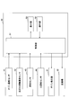
- the air purifying device 10 includes a cleaning unit 20, a circulation unit 30, a detection unit 40, and a control device 50.
- the cleaning unit 20, the circulation unit 30, and the detection unit 40 are installed in the indoor space (indoor space) S of the vehicle 12, and the main body of the control device 50 is outside the space S and inside the vehicle 12. It is provided. Further, the cleaning unit 20 and the circulation unit 30 are provided in the device main body 11 of the air purifying device 10.
- the device main body 11 has a casing provided with an internal space for accommodating the cleaning unit 20 and the circulation unit 30.
- the internal space constitutes a ventilation path for circulating the inhaled air in a predetermined direction.
- a casing formed in a tubular shape, a rectangular parallelepiped shape, or the like can be used as the casing of the device main body 11.
- the cleaning unit 20 purifies the air in the space S, and has a purifying substance generating unit 21 and a dust collecting filter 22.
- the cleaning unit 20 includes a purification substance generating unit 21 and a dust collecting filter 22 in this order along the air blowing direction.
- the purifying substance generating unit 21 generates ozone in the air using oxygen in the air taken in by the blower 32 described later as a raw material, and functions as an ozone generating unit. Then, the purifying substance generating unit 21 is electrically connected to the control unit 51 (see FIG. 2) described later of the control device 50, and is controlled by the control unit 51 (see FIG. 2).
- the purifying substance generating unit 21 can be of any type as long as it can generate ozone.
- a discharge type one in which the discharge electrode and the counter electrode are alternately arranged in a state of facing each other can be used. In this discharge type, when a voltage is applied to both electrodes, a discharge occurs between both electrodes.
- oxygen contained in the air is activated, and a part of the dissociated or excited oxygen is changed to ozone (O 3 ).
- O 3 ozone
- Ozone oxidizes with the odorous components contained in the air to decompose and remove the odorous components.
- the odor component is, for example, toluene
- the odor component reacts with ozone and is decomposed into carbon dioxide (CO 2 ) and water (H 2 O), which are reaction products, as shown in the following formula (1).
- CO 2 carbon dioxide
- H 2 O water
- the amount of ozone generated (amount of ozone generated) in the purifying substance generating unit 21 can be controlled (increase / decrease, start / stop, etc.) by adjusting the amount of discharge by the control unit 51 (see FIG. 2) described later.
- the dust collecting filter 22 is provided on the downstream side in the air flow direction from the purifying substance generating unit 21.
- the dust collecting filter 22 collects solid matter such as soot and dust in the air.
- the dust collecting filter 22 may be any as long as it can collect soot and the like in the air.
- a non-woven fabric made of fine metal wires, natural fibers or synthetic fibers formed in a pleated shape can be used.
- the circulation unit 30 has an intake port 31, a blower 32, and an exhaust port 33.
- the intake port 31 is for sucking the air in the space S into the inside of the device main body 11.
- the intake port 31 is formed in a slit shape on the side surface of the device main body 11.
- the intake port 31 may be formed on the upper surface or the lower surface of the device main body 11.
- the blower 32 is provided on the upstream side in the air flow direction with respect to the purifying substance generating portion 21 in the apparatus main body 11 and in the vicinity of the intake port 31. Then, the blower 32 is electrically connected to the control unit 51 (see FIG. 2) of the control device 50, and is controlled by the control unit 51 (see FIG. 2).
- the blower 32 for example, an axial fan that blows air in the rotation axis direction by propeller-shaped blades can be used.
- the blower 32 includes a motor (not shown) and a plurality of blades fixed to the rotating shaft of the motor.
- the blower 32 is supplied with power from an external power source, and the motor is driven to rotate the blades to suck air into the internal space of the apparatus main body 11 and purify the sucked air into the purifying substance generating unit 21 and the dust collecting filter. It is passed in the order of 22, and is discharged from the exhaust port 33 into the space S.
- the rotation speed of the blower 32 is controlled by a control unit 51 (see FIG. 2) described later.
- the exhaust port 33 is for discharging the air (clean air) purified by the cleaning unit 20 in the apparatus main body 11 to the space S in the vehicle.
- the exhaust port 33 is formed in a slit shape on the side surface of the device main body 11.
- the intake port 31 may be formed on the upper surface of the device main body 11.
- the detection unit 40 includes a purifying substance concentration sensor 41 which is a purifying substance concentration measuring unit, a reaction product concentration sensor 42 which is a reaction product concentration measuring unit, an odor sensor 43 which is an odor measuring unit, and a human sensing sensor which is a human detecting unit. Has 44. Each of these sensors is provided in the space S. Further, the detection unit 40 is electrically connected to the control unit 51 (see FIG. 2) of the control device 50, and transmits each detection signal to the control unit 51 (see FIG. 2).
- the purifying substance concentration sensor 41 measures the ozone concentration of the air in the space S, and functions as an ozone concentration sensor.
- a semiconductor type sensor or the like including a semiconductor element can be used as the purifying substance concentration sensor 41.
- ozone is adsorbed on the surface of the semiconductor element and the resistance value of the semiconductor element changes, so that the ozone concentration is measured.
- the purifying substance concentration sensor 41 is preferably provided at a position close to the intake port 31 in the space S.
- the position closer to the intake port 31 is easier to measure the ozone concentration in the state after the ozone released into the space S reacts with the odor component than the position closer to the exhaust port 33. Therefore, the ozone concentration contained in the air in the space S can be stably measured.
- the purifying substance concentration sensor 41 may be installed at a position far from the device main body 11 in the space S.
- the reaction product concentration sensor 42 measures the concentration (moisture concentration (humidity)) of water, which is one of the reaction products generated when the odorous component is decomposed by ozone.
- concentration moisture concentration (humidity)
- a known water concentration meter (moisture meter) or the like can be used as the reaction product concentration sensor 42.
- the type of the moisture concentration meter is not limited, and as the moisture concentration meter, for example, a polymer capacitance type humidity sensor or the like can be used.
- the reaction product concentration sensor 42 may be provided at a position where the water concentration in the space S can be measured.
- the odor sensor 43 measures the concentration of the odor component in the space S.
- a semiconductor type sensor or the like using a metal oxide semiconductor such as tin oxide or zinc oxide can be used as the odor sensor 43.
- oxygen adsorbed on the surface of a semiconductor element reacts with an odor component (surface reaction), and oxygen is released, so that the resistance value of the semiconductor element changes. From this change in resistance value, the concentration of odorous components in the air is measured.
- the odor sensor 43 may be of a type other than the semiconductor type.
- the person detection sensor 44 detects the presence or absence of a person in the space S.
- the human detection sensor 44 for example, an infrared sensor that detects the heat of an animal such as a person or a pet with infrared rays can be used.
- the human detection sensor 44 is preferably used as the human detection unit, but any sensor that can detect the presence or absence of a person or an animal may be used.
- the control device 50 includes a control unit 51 which is a main body, an operation unit 52 connected to the control unit 51, and a display unit 53.
- the control unit 51 is provided outside the space S and inside the vehicle 12, and the operation unit 52 and the display unit 53 are provided inside the space S.
- the control unit 51 is connected to each member constituting the air purifying device 10 such as the purifying substance generating unit 21 and the blower 32, and the display unit 53 in a controllable manner.
- the control unit 51 has a storage means for storing a control program and various storage information, and a calculation means for operating based on the control program.
- the control unit 51 is realized by the arithmetic means reading and executing a control program or the like stored in the storage means.
- the control unit 51 receives the measurement result from the detection unit 40.
- the control unit 51 controls the amount of ozone generated by the purifying substance generation unit 21 and the rotation speed of the blower 32 based on the measurement result of the detection unit 40.
- the control unit 51 has an ozone concentration measured by the purifying substance concentration sensor 41, a water concentration measured by the reaction product concentration sensor 42, and an odor component concentration in the space S measured by the odor sensor 43. And the signal of the detection result of the presence or absence of the person detected by the person detection sensor 44 is received.
- the control unit 51 calculates the ozone concentration, the water concentration, or the concentration of the odorous component in the air based on the signals received from these sensors, determines the presence or absence of a person, and supplies ozone to the purifying substance generating unit 21.
- a signal to be generated or a signal to rotate the blower 32 is output to the blower 32.
- the ozone generation amount or the air blowing amount is adjusted.
- the control unit 51 controls the purifying substance generating unit 21 to control the amount of ozone generated when the amount of increase in water concentration per unit time becomes equal to or less than a predetermined value.
- the control unit 51 determines the relationship between the amount of ozone generated by the purifying substance generation unit 21 and the volume of the space S, and the amount of increase in the concentration of reaction products (for example, water, CO 2, etc.) per unit time. It may be stored in a storage means in advance. In the present embodiment, it is preferable that the storage means stores the relationship between the amount of ozone generated by the purifying substance generating unit 21 and the volume of the space S, and the amount of increase in the water concentration per unit time. In this case, the control unit 51 compares the stored value stored in the storage means with the actually measured value measured by the purifying substance concentration sensor 41, and the amount of increase in the water concentration in the space S per unit time. Can be determined whether or not is less than or equal to a predetermined value.
- the control unit 51 controls the purifying substance generating unit 21 and the blower 32 to change the operating state of the air purifying device 10 to a ventilation mode, a purifying substance regular mode (hereinafter, referred to as an ozone regular mode in the present embodiment) and a purifying substance. It can be controlled to any of three operation modes of fumigation mode (hereinafter, referred to as ozone fumigation mode in this embodiment).
- the ventilation mode is an operation mode in which the air sucked into the device main body 11 is discharged from the inside of the device main body 11 into the space S without generating ozone in the purifying substance generating unit 21.
- the control unit 51 stops the operation of the purifying substance generating unit 21 and controls so that only the blower 32 is operated.
- the purifying substance generating unit 21 In the ozone regular mode, the purifying substance generating unit 21 generates low-concentration ozone, and the cleaning unit 20 uses the low-concentration ozone to clean the clean air together with the low-concentration ozone from the inside of the apparatus main body 11 into the space S. This is the operation mode for discharging.
- the control unit 51 operates the blower 32 and controls the purifying substance generation unit 21 to generate low-concentration ozone.
- the purifying substance generating unit 21 In the ozone fumigation mode, the purifying substance generating unit 21 generates high-concentration ozone, and the cleaning unit 20 uses the high-concentration ozone to clean the clean air together with the high-concentration ozone from the inside of the apparatus main body 11 to the space S. This is the operation mode for discharging.
- the control unit 51 operates the blower 32 and controls the purifying substance generation unit 21 to generate a high concentration of ozone.
- the first method is a method in which the amount of ozone generated by the purifying substance generating unit 21 is changed to keep the amount of air blown by the blower 32 constant.
- the second method is a method of varying the amount of air blown by the blower 32 while keeping the amount of ozone generated by the purifying substance generating unit 21 constant.
- the third method is a method of varying both the amount of ozone generated by the purifying substance generating unit 21 and the amount of air blown by the blower 32.
- the low ozone concentration means a concentration in which the ozone concentration is in the range of a standard value or less that is safe for the human body, and is 0.1 ppm or less, preferably 0.05 ppm or less.
- a high ozone concentration means that the ozone concentration is higher than the standard value that is safe for the human body, and the higher the concentration is preferable in order to efficiently decompose the odorous components, but the effect on the human body is affected. I am concerned. Therefore, it is preferable to perform the ozone fumigation mode using high-concentration ozone after confirming with the human detection sensor 44 that no person, pet, or the like is in the space S in the vehicle.
- the operation unit 52 is arranged in the space S, and is a signal for controlling the presence / absence of ozone generation and the amount of ozone generated in the purifying substance generation unit 21, the presence / absence of operation of the blower 32, the rotation speed thereof, and the like by an external operation. Has a function of transmitting to the control unit 51.
- the display unit 53 is arranged in the space S, and the presence / absence and amount of ozone generated in the purifying substance generating unit 21, the presence / absence of operation of the blower 32 and its rotation speed, and the ozone concentration measured by the purifying substance concentration sensor 41. It has a function of displaying the water concentration measured by the reaction product concentration sensor 42, the concentration of the odor component in the space S measured by the odor sensor 43, the presence or absence of a person detected by the human sensing sensor 44, and the like. In addition, the display unit 53 displays the end of the air cleaning method, which will be described later.
- the operation operation of the air purifier 10 having the above configuration will be described.
- the control unit 51 is energized and the operation of the air purifier 10 starts.
- the operator selects the operation mode from the ventilation mode, the ozone regular mode, or the ozone fumigation mode on the operation unit 52. First, a case where the ventilation mode is performed will be described.
- a signal for setting the operation mode to the ventilation mode is transmitted from the operation unit 52 to the control unit 51.
- the control unit 51 receives the signal of the operation unit 52 and outputs a signal for driving the blower 32 to the blower 32 to rotate the blades of the blower 32.
- the air in the space S is sucked into the apparatus main body 11 from the intake port 31.
- the air sucked into the main body 11 of the apparatus passes through the purifying substance generating unit 21, and the dust collecting filter 22 removes solid matter such as soot and dust in the air.
- the air from which solids have been removed is also called clean air.
- the clean air that has passed through the dust collection filter 22 is pressure-fed by the blower 32 and discharged from the exhaust port 33 into the space S.
- the clean air discharged from the exhaust port 33 into the space S diffuses in the space S and is mixed with the air containing the odor component to become the air containing the odor component.
- Air circulates due to natural convection in space S. A part of the air circulating in the space S is sucked into the device main body 11 from the intake port 31, and is cleaned again by the air purifying device 10. By repeatedly cleaning the air in the space S with the air purifying device 10, the air in the space S becomes air having a low concentration of solid matter such as soot and dust.
- the operation mode is set to the ozone regular use mode.
- the operation unit 52 transmits a signal to the control unit 51 to change the operation mode to the ozone normal mode.
- the control unit 51 receives the signal of the operation unit 52 and outputs a signal for driving the blower 32 to the blower 32 to rotate the blades of the blower 32 and generate a signal for generating low-concentration ozone as a purifying substance.
- the purifying substance generating unit 21 is operated.
- the air sucked into the apparatus main body 11 from the intake port 31 reaches the purifying substance generating section 21, the air passes through the purifying substance generating section 21 and low-concentration ozone is mixed in the air.
- the air containing low-concentration ozone that has passed through the purifying substance generating section 21 is pumped by the blower 32 after the solid matter such as dust in the air is removed by the dust collecting filter 22, and is sent from the exhaust port 33 into the space S. It is discharged to the air and diffuses in the space S.
- the air containing ozone diffuses in the space S from the purifying substance generating unit 21, odorous components and the like contained in the air are decomposed and removed by an oxidative reaction with ozone. As a result, the air is deodorized and sterilized. Further, when not only the odorous component contained in the air but also the odorous component adhering to the seat or wall in the vehicle comes into contact with ozone, it is deodorized and sterilized by oxidizing reaction with ozone. On the other hand, the ozone mixed in the air by the purifying substance generating unit 21 disappears by reacting with the odorous component in the air.
- air deodorized and sterilized by ozone is also called clean air.
- the clean air includes not only the case where the air does not completely contain the odor component but also the case where the odor component is contained in a very small amount.
- the clean air discharged from the exhaust port 33 into the space S diffuses in the space S and is mixed with the air containing the odor component to become the air containing the odor component.
- the air circulates in the space S. A part of the circulating air is sucked into the device main body 11 and cleaned again by the air purifying device 10. By repeatedly cleaning the air in the space S with the air purifying device 10, the air in the space S becomes deodorized and sterilized air having a low concentration of solid matter.
- the ozone concentration, water concentration, and odor component concentration in the air in the space S are measured by the purifying substance concentration sensor 41, the reaction product concentration sensor 42, and the odor sensor 43. These measurement results are sent to the control unit 51.
- the presence or absence of a person in the vehicle 12 is detected by the person detection sensor 44, and the detection result is sent to the control unit 51.
- the control unit 51 outputs a signal for controlling the purifying substance generating unit 21 and the blower 32, respectively, based on the detection results of each of these sensors.
- the ozone fumigation mode is the same as the ozone regular mode except that the control unit 51 outputs a signal to generate a high concentration ozone to the purifying substance generating unit 21 to generate a high concentration ozone from the purifying substance generating unit 21. Shows the operation.
- ozone fumigation mode ozone is consumed by reacting with the odor component while the odor component is present in the air, but the air sucked into the apparatus main body 11 is newly higher than the purifying substance generating unit 21. Concentration of ozone is supplied. Therefore, when the odorous component that reacts with ozone in the air disappears, the ozone concentration in the air rises at a constant rate. Ozone naturally decomposes and disappears in the process of air being released from the purifying substance generating unit 21 into the space S, but the decomposition rate is the rate at which ozone reacts with odorous components and decomposes. It is much lower than the supply rate of ozone supplied into the air from the purifying substance generator 21. Therefore, it is not necessary to particularly consider the decomposition rate of ozone when determining the increase or decrease of the ozone concentration.
- the ozone fumigation mode since high-concentration ozone that may affect the human body is used, it is desirable to start the operation after confirming that there are no people, pets, etc. in the space S by the human detection sensor 44. .. In addition, even after the ozone generation is stopped, the user is notified whether or not the vehicle can be boarded after the ozone concentration falls below the safe concentration, or the door lock is unlocked after the ozone concentration falls below the safe concentration. desirable.
- Air purification method> an example of an air purifying method for purifying air using the air purifying device 10 having the above configuration will be described with reference to FIGS. 3 and 4. Here, a case where the odor component is toluene will be described.
- FIG. 3 is a flowchart illustrating an air cleaning method
- FIG. 4 is a diagram showing an example of the relationship between time and the water concentration and the toluene concentration.
- the control unit 51 selects the ozone fumigation mode as the operation mode, operates the purification substance generation unit 21 and the blower 32, sucks the air in the space S, and the purification substance generation unit 21. To generate a high concentration of ozone in (step S11).
- the water concentration in the space S is measured by the reaction product concentration sensor 42 (concentration measurement step: step S12).
- the measurement result of the water concentration is sent to the control unit 51.
- control unit 51 calculates whether or not the amount of increase in the water concentration per unit time measured by the reaction product concentration sensor 42 is equal to or less than a predetermined value (step S13).
- the predetermined value means that the amount of increase in water concentration per unit time is, for example, 3.0% or less, and is preferably the same or about the same.
- the same degree means a range that allows an error of ⁇ 1.0%.
- the value of water concentration at the start of unit time ⁇ T the value of water concentration at the end of unit time ⁇ T.
- the ratio to the difference between the value of the water concentration at the start of the unit time ⁇ T can be used. ((Value of water concentration at the end of unit time ⁇ T)-(Value of water concentration at the start of unit time ⁇ T)) / (Value of water concentration at the start of unit time ⁇ T) ⁇ ⁇ ⁇ (I)
- the average value of the sum of the water concentration in the unit time ⁇ T the value of the water concentration in the middle time of the unit time ⁇ T, or the like can be used.
- step S13 when the amount of increase in water concentration per unit time exceeds a predetermined value (step S13: No), the control unit 51 keeps the purifying substance generating unit 21 in operation. Then, the control unit 51 measures the water concentration in the space S with the reaction product concentration sensor 42 (step S12), and calculates whether or not the amount of increase in the water concentration per unit time is equal to or less than a predetermined value (step S13). .. For a predetermined time from the start of operation of the purifying substance generating unit 21, ozone reacts with an odor component (toluene in this case) to generate a reaction product (water and CO 2 ), so that water, which is one of the reaction products, The concentration continues to increase.
- an odor component toluene in this case
- a high concentration of ozone is newly supplied to the air from the purifying substance generating unit 21. Therefore, ozone reacts with toluene to produce reaction products (CO 2 and water), and the water concentration increases from M1 to M2.
- reaction products CO 2 and water
- the lengths of the times T1 and T2, the degree of change in the concentration of toluene, and the degree of change in the water concentration depend on the concentration of toluene in the space S of the vehicle and the like.
- step S13 when the amount of increase in water concentration per unit time is equal to or less than a predetermined value (step S13: Yes), the control unit 51 stops the generation of high-concentration ozone in the purifying substance generating unit 21 (adjustment).
- Step S14 When a predetermined time elapses from the start of ozone generation and almost all the toluene existing in the space S is decomposed, the decomposition of toluene ends. As a result, since there is almost no substance that reacts with ozone in the space S, the concentration of the reaction product (CO 2 and water) hardly increases and becomes a predetermined value or less.
- the toluene that reacts with ozone is almost eliminated in the space S, so that the amount of increase in the water concentration per unit time is equal to or less than a predetermined value at the time T2. It becomes almost constant.
- the amount of increase in water concentration per unit time is less than or equal to the predetermined value even once, it can be determined that the amount of increase in water concentration per unit time is less than or equal to the predetermined value, but the present invention is not limited to this.
- a predetermined value for example, as shown in FIG. 5, the amount of increase in water concentration ⁇ C per unit time ⁇ T is continuously performed a plurality of times (for example,). (3 times or more), the case where they are almost the same can be used. In this case, it can be determined that the amount of increase in water concentration per unit time is equal to or less than a predetermined value.
- the amount of increase in water concentration per unit time is preferably constant. If the amount of increase in water concentration is constant, the control unit 51 can easily determine that the amount of increase in water concentration per unit time is equal to or less than a predetermined value, so that all the odorous components of S in the space have been removed. It is easier to detect things more reliably.
- the control unit 51 determines that the amount of increase in the water concentration per unit time measured by the reaction product concentration sensor 42 is equal to or less than a predetermined value, the height of the purification substance generation unit 21 is increased. The generation of concentrated ozone is stopped (forced termination) (see P3 at the time point in FIG. 4). As a result, the amount of ozone generated in the space S can be reduced.
- the generation of high-concentration ozone is changed to the generation of low-concentration ozone without stopping the purifying substance generating section 21 other than stopping the purifying substance generating section 21. Switch and gradually reduce the ozone concentration. Then, the ventilation mode may be finally switched, or the purifying substance generating unit 21 may be stopped to stop the generation of ozone.
- the purifying substance generating section 21 When the operation of the purifying substance generating section 21 is stopped, the supply of ozone from the purifying substance generating section 21 to the space S is stopped, so that the ozone newly generated in the space S disappears and almost all the toluene to be decomposed remains. Absent. Therefore, the water concentration in the space S becomes constant. Since the ozone in the space S is naturally decomposed, the ozone concentration in the space S gradually decreases.
- the air purifier 10 includes a reaction product concentration sensor 42 and a control unit 51.
- the control unit 51 controls the purifying substance generation unit 21 to control the ozone generation amount when the increase amount of the water concentration per unit time becomes equal to or less than a predetermined value.
- ozone generated from the purifying substance generating unit 21 is supplied into the space S, it decomposes odorous components (for example, toluene and the like) existing in the space S to generate water which is one of the reaction products.
- odorous components for example, toluene and the like
- the control unit 51 controls the purifying substance generating unit 21 and is supplied from the purifying substance generating unit 21. Control the amount of ozone generated. Therefore, since the air purifier 10 can more accurately determine the end of deodorization in the space S, it is possible to stop the generation of ozone at the optimum timing when the deodorization is completed.
- the air purifying device 10 can suppress the generation of excess ozone in the purifying substance generating unit 21, it is possible to efficiently remove the odor component while reducing the wasteful energy consumption. Therefore, according to the air purifier 10, it is possible to reduce discomfort to the user of the next vehicle, and it is possible to reduce unnecessary time required for deodorizing work while suppressing wasteful power consumption. be able to.
- the air purifier 10 can reduce the amount of excess ozone remaining in the space S by stopping the generation of ozone at the optimum timing, even if the odor sensor 43 is a semiconductor sensor, it can be reduced.
- the odor sensor 43 can stably measure the concentration of the odor component. For example, when the odor sensor 43 is a semiconductor sensor, if the ozone generated during deodorization exists in the space S of the vehicle, oxygen ions adsorbed on the surface of the semiconductor element increase, so that the odor sensor 43 It may reduce the measurement performance of the odorous component of 43.
- the odor sensor 43 may measure the concentration of the odor component to be small, and the concentration of the odor component may not be accurately measured. As a result, the operation of the purifying substance generating unit 21 may be stopped. In the present embodiment, it is possible to reduce the amount of excess ozone remaining in the space S, so even if the odor sensor 43 is a semiconductor sensor, oxygen ions that are excessively adsorbed on the surface of the semiconductor element of the odor sensor 43 The amount of is suppressed.
- the air purifying device 10 uses a semiconductor sensor for the odor sensor 43, it is possible to reduce the excess adsorption of ozone to the semiconductor surface of the semiconductor element of the odor sensor 43, so that the odor sensor 43 detects the odor component. It is possible to suppress the deterioration of the performance to be performed. Therefore, the air purifier 10 can stably measure the concentration of the odor component with the odor sensor 43 with high accuracy.
- the control unit 51 can determine in advance the amount of increase in water concentration per unit time, which is calculated based on the amount of ozone generated and the volume of the space S, as a predetermined value. By comparing the measured value with the predetermined value, the control unit 51 can easily determine whether or not the amount of increase in the water concentration in the space S per unit time has reached the predetermined value. This makes it easier for the control unit 51 to make a determination for controlling the purifying substance generating unit 21.
- the amount of increase in water concentration per unit time is preferably constant.
- “constant” means that the amount of increase in water concentration per unit time is almost zero.
- the amount of increase in water concentration is constant, it can be more reliably measured that all the odorous components in the space S have been removed. Therefore, by stopping (forced termination) the operation of the purifying substance generating unit 21 at the timing when the amount of increase in water concentration per unit time becomes constant, the amount of ozone generated in the space S can be reduced, and more. The generation of ozone can be stopped optimally. Therefore, according to the air purifier 10, the odor component can be removed more efficiently while further reducing the wasteful energy consumption.
- the air purifier 10 is controlled by the control unit 51 into one of three modes: ventilation mode, ozone regular mode, and ozone fumigation mode. As a result, the air purifying device 10 can appropriately purify the air according to the concentration of the odor component in the space S.
- the air purifier 10 preferably includes an odor sensor 43. By including the odor sensor 43, the air purifier 10 can detect the odor component in the space S.
- the air purifier 10 preferably includes a human detection sensor 44. By providing the air purifying device 10 with the human sensing sensor 44, it is possible to confirm whether or not a person exists in the space S. As a result, when the air purifier 10 is operating in the ozone fumigation mode, the air purifier 10 can stably perform the ozone fumigation mode in a state where no person is present in the space S.
- the air purifying device 10 preferably includes a purifying substance concentration sensor 41. By including the purifying substance concentration sensor 41, the air purifying device 10 can measure the concentration of ozone in the space S.
- the air purifying device 10 purifies the air in the space S inside the vehicle 12 .
- the air purifying device 10 purifies the air in the space S at the optimum timing. can do. Therefore, the air purifier 10 is suitably used not only as a vehicle 12 but also as an air purifier that is installed in, for example, a train, an airplane, a building, or the like to purify the air in those spaces. Can be done.
- the air purifier 10 deodorizes the partition space of the smoke separation room installed in the kitchen of a store, a public facility, the building space of a garbage collection place, the internal storage space of an air conditioner, a refrigerator, etc. It may be provided in a route or the like.
- the reaction product concentration sensor 42 provided in the space S is measures the moisture concentration as the concentration of response product, using a CO 2 concentration sensor for measuring the concentration of CO 2 You may.
- a CO 2 concentration sensor a known gas sensor such as a non-dispersive infrared (NDIR) type sensor can be used.
- both a sensor for measuring the water concentration and a sensor for measuring the CO 2 concentration may be provided.
- the device main body 11 having the cleaning unit 20 and the circulation unit 30 is installed in the space S inside the vehicle 12, but is not limited to this.
- the device main body 11 may be provided inside the vehicle 12 but outside the space S, and the intake port 31 and the exhaust port 33 of the circulation unit 30 may be opened toward the inside of the space S.
- the purifying substance generating unit 21 generates ozone as a purifying substance for purifying the odorous component, but any substance that can decompose the odorous component contained in the air to generate a reaction product may be used.
- an oxidizing agent such as hypochlorous acid (HClO) or hydrogen peroxide (H 2 O 2 ) may be generated.
- the reaction product concentration sensor 42 can use a hydrochloric acid concentration sensor capable of measuring the hydrochloric acid concentration in the air in the space S.
- the odorous component is represented as RH as in the following formula (2)
- the odorous component reacts with HClO to produce hydrochloric acid (HCl), which is a reaction product. Therefore, the reaction product concentration sensor 42 can detect hydrochloric acid using a hydrochloric acid concentration sensor that can measure the hydrochloric acid concentration in the air in the space S.
- the purifying substance concentration sensor 41 may use a hypochlorous acid concentration sensor capable of measuring the hypochlorous acid concentration in the air in the space S. it can.
- a measuring device including a fluorescent reagent that reacts with hypochlorous acid generated by the purifying substance generating unit 21 and emits light can be used.
- the fluorescent reagent provided in the purifying substance concentration sensor 41 emits light when it comes into contact with hypochlorous acid.
- the purifying substance concentration sensor 41 can stably measure the presence / absence of hypochlorous acid contained in the air in the space S and the concentration of hypochlorous acid according to the presence / absence of light emission and the light emission intensity of the fluorescent reagent. Further, as the purifying substance concentration sensor 41, in addition to the above-mentioned measuring device, a hydrochloric acid gas sensor using carbon nanotubes has a small size and high sensitivity, and can be preferably used.
- the purifying substance generating unit 21 and the blower 32 are incorporated together in the device main body 11, but they do not have to be incorporated together in the device main body 11.
- the blower 32 is provided on the upstream side of the purifying substance generating unit 21 in the apparatus main body 11 in the air flow direction, but on the downstream side of the purifying substance generating unit 21 in the air flow direction. It may be provided.
- the cleaning unit 20 includes the dust collecting filter 22, but when it is not necessary to collect solid matter such as soot and dust in the air, the cleaning unit 20 does not include the dust collecting filter 22. You may.
- the dust collecting filter 22 is used to collect solids such as soot and dust in the air, but it is sufficient if the solids such as soot and dust can be removed from the air.
- an electric dust collector may be used instead of the dust collector filter 22.
- An electrostatic precipitator is a device that applies a high voltage to air to charge dust and the like contained in the air and adsorb it on a dust collecting plate to remove it. By using the electrostatic precipitator, the maintenance cycle becomes longer than when the dust collector filter 22 is used, and the number of maintenances can be reduced.
- control device 50 is provided with the control unit 51 inside the vehicle 12 and outside the space S, and the operation unit 52 and the display unit 53 are provided inside the space S, but the present invention is not limited to this.
- the control device 50 may be provided in the device main body 11, or only the control unit 51 may be provided in the device main body 11. Further, the operation unit 52 and the display unit 53 of the control device 50 may be provided on the outside of the vehicle 12, or the control device 50 may be provided on the outside of the vehicle 12.
- Air purifier 20 Purifier 21 Purified substance generator 30 Circulator 32 Blower 40 Detector 41 Purified substance concentration sensor (Purified substance concentration measuring unit) 42 Reaction product concentration sensor (reaction product concentration part) 43 Odor sensor (odor measurement unit) 44 motion sensor (presence sensor) 51 Control unit S space
Abstract
空気清浄装置は、空間内の空気中に含まれる臭気成分を除去する清浄部と、前記空間内の前記空気を前記清浄部に供給し、前記清浄部で清浄された清浄空気を前記空間内に排出する循環部と、を有し、前記清浄部は、前記臭気成分を分解する浄化物質を発生させる浄化物質発生部を備える空気清浄装置であって、前記臭気成分を前記浄化物質で分解した際に発生する反応生成物の濃度を測定する反応生成物濃度測定部と、単位時間当たりの前記反応生成物の濃度の増加量が所定値以下になった場合に、前記浄化物質発生部を制御して、前記浄化物質の発生量を制御する制御部と、を備える。
Description
本発明は、空気清浄装置及び空気清浄方法に関する。
車両の内部や建物の室内等の空気に含まれる、悪臭物質や揮発性有機化合物(VOC)等の臭気成分を、オゾンや次亜塩素酸等を酸化剤として利用して、除去(脱臭)及び殺菌することで、臭気成分を含む空気を清浄化する空気清浄装置がある。
このような空気清浄装置として、例えば、ファン、オゾン発生器、切換ダンパ、コントロールユニット及び臭気センサを備えた、車両の換気・脱臭装置がある(例えば、特許文献1参照)。従来の、車両の換気・脱臭装置では、臭気センサで検知された車内の臭気濃度に応じて、コントロールユニットにより、ファン、オゾン発生器及び切換ダンパを制御して、換気モード、オゾン常用モード及びオゾン燻蒸モードの3つのモードの切換えを行っている。車内にしみついた強烈な異臭を脱臭する際には、オゾン燻蒸モードを選択して、基準値を超える高濃度のオゾンを所定時間発生させて、車内にしみついた強烈な異臭を効果的に脱臭している。
臭気センサは、一般に、酸化物半導体や有機半導体で形成された半導体素子を用いて形成された半導体式センサである場合が多い。半導体式センサでは、半導体素子の表面に負電荷吸着している酸素が臭気成分と反応(表面反応)し、半導体素子の表面の酸素が離脱して臭気成分が吸着することによって、半導体素子の抵抗値が変化する。半導体式センサは、この性質を利用して、空気中の臭気成分の濃度を測定している。
しかしながら、特許文献1の、車両の換気・脱臭装置では、異臭の強さに関わらず、車両内にオゾンをタイマーで一律に所定時間発生させているだけであるため、脱臭が十分でなかったり、脱臭を過剰にやり過ぎる可能性が高かった。脱臭が十分でないと、車両内の異臭が十分除去されず残るため、車両の使用者に対して不快感を与えることになる。一方、脱臭を過剰にやり過ぎると、オゾンを過剰に発生させることになるため、無駄な電力消費や脱臭作業に必要以上に時間を要することになる。
そのため、空気中の臭気成分を除去する、オゾンや次亜塩素酸等のような浄化物質の発生量を適切に抑制する必要がある。
本発明の一態様は、脱臭が終了した最適なタイミングで浄化物質の発生を停止できる空気清浄装置を提供することを目的とする。
本発明に係る空気清浄装置の一態様は、空間内の空気中に含まれる臭気成分を除去する清浄部と、前記空間内の前記空気を前記清浄部に供給し、前記清浄部で清浄された清浄空気を前記空間内に排出する循環部と、を有し、前記清浄部は、前記臭気成分を分解する浄化物質を発生させる浄化物質発生部を備える空気清浄装置であって、前記臭気成分を前記浄化物質で分解した際に発生する反応生成物の濃度を測定する反応生成物濃度測定部と、単位時間当たりの前記反応生成物の濃度の増加量が所定値以下になった場合に、前記浄化物質発生部を制御して、前記浄化物質の発生量を制御する制御部と、を備える。
本発明に係る空気清浄装置の一態様は、脱臭が終了した最適なタイミングで浄化物質の発生を停止できる。
以下、本発明の実施形態について、詳細に説明する。なお、説明の理解を容易にするため、各図面において同一の構成要素に対しては同一の符号を付して、重複する説明は省略する。また、図面における各部材の縮尺は実際とは異なる場合がある。
<空気清浄装置>
一実施形態に係る空気清浄装置について説明する。本実施形態では、一例として、空気清浄装置を車両の室内空間(空間)の空気中に含まれる臭気成分を清浄する場合について説明する。なお、臭気成分とは、悪臭物質や揮発性有機化合物(VOC)等をいい、たばこ臭、ペット臭もしくは人体から出る体臭、又は加齢臭等をいう。具体的には、悪臭物質として、メチルメルカプタン、トリメチルアミン、イソブタノール等が挙げられ、揮発性有機化合物として、トルエン及びキシレン等が挙げられる。また、臭気成分を清浄する際に用いる浄化物質として、オゾン、次亜塩素酸、過酸化水素等が挙げられる。以下、臭気成分がトルエンで、浄化物質がオゾンである場合について説明する。
一実施形態に係る空気清浄装置について説明する。本実施形態では、一例として、空気清浄装置を車両の室内空間(空間)の空気中に含まれる臭気成分を清浄する場合について説明する。なお、臭気成分とは、悪臭物質や揮発性有機化合物(VOC)等をいい、たばこ臭、ペット臭もしくは人体から出る体臭、又は加齢臭等をいう。具体的には、悪臭物質として、メチルメルカプタン、トリメチルアミン、イソブタノール等が挙げられ、揮発性有機化合物として、トルエン及びキシレン等が挙げられる。また、臭気成分を清浄する際に用いる浄化物質として、オゾン、次亜塩素酸、過酸化水素等が挙げられる。以下、臭気成分がトルエンで、浄化物質がオゾンである場合について説明する。
図1は、一実施形態に係る空気清浄装置を車両に設置した状態を示す図である。なお、図1では、車両は停車しており、車内から人やペット(動物)等は出て、車内には人やペット(動物)等がいない状態である。
図1に示すように、空気清浄装置10は、清浄部20、循環部30、検知部40及び制御装置50を有する。そして、清浄部20、循環部30及び検知部40は、車両12の室内の空間(室内空間)Sに設置されており、制御装置50の本体は、空間Sの外側であって車両12内に設けられている。また、清浄部20及び循環部30は、空気清浄装置10の装置本体11内に設けられている。
装置本体11は、清浄部20及び循環部30を収容する内部空間を備えるケーシングを有する。内部空間は、吸入した空気を所定方向に流通させるための通気路を構成する。装置本体11のケーシングとしては、例えば、筒状や直方体状等に形成されたものを用いることができる。
(清浄部)
清浄部20は、空間S内の空気を清浄するものであり、浄化物質発生部21及び集塵フィルタ22を有する。清浄部20は、浄化物質発生部21及び集塵フィルタ22を空気の送風方向に沿ってこの順に備えている。
清浄部20は、空間S内の空気を清浄するものであり、浄化物質発生部21及び集塵フィルタ22を有する。清浄部20は、浄化物質発生部21及び集塵フィルタ22を空気の送風方向に沿ってこの順に備えている。
浄化物質発生部21は、後述する送風機32で取り込んだ空気中の酸素を原料として、空気中にオゾンを発生させるものであり、オゾン発生部として機能する。そして、浄化物質発生部21は、制御装置50の、後述する制御部51(図2参照)と電気的に接続され、制御部51(図2参照)によって制御される。浄化物質発生部21は、オゾンを発生できるものであれば、どのような方式のものでも用いることができる。例えば、浄化物質発生部21として、放電電極と対向電極とを互いに向かい合った状態で交互に配置してなる放電式のものを用いることができる。この放電式では、両電極に電圧を印加すると両電極間で放電が生じる。放電を生じている電極間に空気を通過させることにより、空気中に含まれる酸素が活性化され、解離又は励起された酸素の一部がオゾン(O3)に変化する。これにより、空気中にオゾンが発生する。そして、発生したオゾンは、空気に含まれた状態で搬送される。オゾンは、空気中に含まれる臭気成分と酸化反応して、臭気成分を分解し、除去する。
臭気成分が、例えばトルエンである場合、下記式(1)のように、臭気成分はオゾンと反応して、反応生成物である、二酸化炭素(CO2)と水(H2O)に分解される。
C7H8+6O3→7CO2+4H2O ・・・(1)
C7H8+6O3→7CO2+4H2O ・・・(1)
浄化物質発生部21でのオゾンの発生量(オゾン発生量)は、後述する制御部51(図2参照)により、放電量を調整することにより、制御(増減、稼働、又は停止等)できる。
集塵フィルタ22は、浄化物質発生部21より空気の流れ方向の下流側に設けられている。集塵フィルタ22は、空気中の煤塵等の固形物を捕集するものである。集塵フィルタ22は、空気中の煤塵等を捕集できるものであればよく、例えば、金属細線、天然繊維又は合成繊維からなる不織布をプリーツ形状に形成したもの等を用いることができる。
(循環部)
循環部30は、吸気口31、送風機32及び排気口33を有する。
循環部30は、吸気口31、送風機32及び排気口33を有する。
吸気口31は、空間S内の空気を装置本体11の内部に吸入するためのものである。吸気口31は、装置本体11の側面にスリット状に形成されている。なお、吸気口31は、装置本体11の上面や下面に形成されていてもよい。
送風機32は、装置本体11内の浄化物質発生部21よりも空気の流れ方向の上流側であって、吸気口31の近傍に設けられる。そして、送風機32は、制御装置50の制御部51(図2参照)と電気的に接続され、制御部51(図2参照)によって制御される。送風機32は、例えば、プロペラ形の羽根によって回転軸方向に風を送る軸流ファンを用いることができる。送風機32は、図示しないモータと、前記モータの回転軸に固定される複数の羽根とで構成される。送風機32は、外部電源より給電され、前記モータが駆動して前記羽根を回転させることにより、装置本体11の内部空間内に空気を吸込み、吸入された空気を浄化物質発生部21、集塵フィルタ22の順に通過させ、排気口33から空間S内に放出させる。なお、送風機32の回転数は、後述する制御部51(図2参照)により制御される。
排気口33は、装置本体11内の清浄部20で清浄された空気(清浄空気)を車内の空間Sに排出するためのものである。排気口33は、装置本体11の側面にスリット状に形成されている。なお、吸気口31は、装置本体11の上面に形成されていてもよい。
(検知部)
検知部40は、浄化物質濃度測定部である浄化物質濃度センサ41、反応生成物濃度測定部である反応生成物濃度センサ42、臭い測定部である臭気センサ43及び人検知部である人感知センサ44を有する。これらのセンサは、それぞれ、空間S内に設けられている。また、検知部40は、制御装置50の制御部51(図2参照)と電気的に接続され、それぞれの検知信号を制御部51(図2参照)に送信する。
検知部40は、浄化物質濃度測定部である浄化物質濃度センサ41、反応生成物濃度測定部である反応生成物濃度センサ42、臭い測定部である臭気センサ43及び人検知部である人感知センサ44を有する。これらのセンサは、それぞれ、空間S内に設けられている。また、検知部40は、制御装置50の制御部51(図2参照)と電気的に接続され、それぞれの検知信号を制御部51(図2参照)に送信する。
浄化物質濃度センサ41は、空間S内の空気のオゾン濃度を測定するものであり、オゾン濃度センサとして機能する。浄化物質濃度センサ41は、半導体素子を備える半導体式センサ等を用いることができる。半導体式センサでは、前記半導体素子の表面にオゾンが吸着して、半導体素子の抵抗値が変化することにより、オゾン濃度が測定される。
浄化物質濃度センサ41は、空間S内の吸気口31に近い位置に設けられることが好ましい。吸気口31に近い位置の方が排気口33に近い位置よりも、空間S内に放出されたオゾンが臭気成分と反応した後の状態のオゾン濃度が測定され易い。そのため、空間Sの空気に含まれるオゾン濃度を安定して測定できる。なお、浄化物質濃度センサ41は、空間S内で、装置本体11から遠い位置に設置されていてもよい。
反応生成物濃度センサ42は、臭気成分をオゾンで分解した際に発生する反応生成物の一つである水の濃度(水分濃度(湿度))を測定する。反応生成物濃度センサ42としては、公知の水分濃度計(水分計)等を用いることができる。水分濃度計の形式は限定されず、水分濃度計として、例えば、高分子静電容量式の湿度センサ等を用いることができる。反応生成物濃度センサ42は、空間S内の水分濃度を測定できる位置に設けられていればよい。
臭気センサ43は、空間S内の臭気成分の濃度を測定する。臭気センサ43は、酸化錫、酸化亜鉛等の金属酸化半導体を使用した半導体式センサ等を用いることができる。半導体式センサでは、半導体素子の表面で表面に吸着している酸素が臭気成分と反応(表面反応)し、酸素が離脱することによって、半導体素子の抵抗値が変化する。この抵抗値の変化から、空気中の臭気成分の濃度が測定される。なお、臭気センサ43は、半導体式以外の他の方式でもよい。
人感知センサ44は、空間S内の人の有無を検知する。人感知センサ44は、例えば、赤外線で人やペット等の動物の熱を感知する赤外線式センサ等を用いることができる。なお、本実施形態では、人検知部として、好適に人感知センサ44を用いたが、人又は動物の有無を検知できるセンサであればよく、例えば、カメラで動作を検知するタイプの人検知部であってもよい。
(制御装置)
制御装置50は、図2に示すように、本体である制御部51と、制御部51に接続されている操作部52と、表示部53を有する。なお、本実施形態では、制御部51は空間Sの外側であって車両12内に設けられ、操作部52、及び表示部53は空間S内に設けられる。
制御装置50は、図2に示すように、本体である制御部51と、制御部51に接続されている操作部52と、表示部53を有する。なお、本実施形態では、制御部51は空間Sの外側であって車両12内に設けられ、操作部52、及び表示部53は空間S内に設けられる。
制御部51は、浄化物質発生部21及び送風機32等の空気清浄装置10を構成する各部材並びに表示部53を制御可能にこれらと接続されている。制御部51は、制御プログラムや各種記憶情報を格納する記憶手段と、制御プログラムに基づいて動作する演算手段とを有する。制御部51は、演算手段が記憶手段に格納されている制御プログラム等を読み出して実行することで実現される。
制御部51は、検知部40からの測定結果を受信する。制御部51は、検知部40の測定結果に基づいて、浄化物質発生部21で発生させるオゾンの発生量及び送風機32の回転速度を制御する。具体的には、制御部51は、浄化物質濃度センサ41で測定されたオゾン濃度、反応生成物濃度センサ42で測定された水分濃度、臭気センサ43で測定された空間S内の臭気成分の濃度及び人感知センサ44で検知された人の有無の検知結果の信号を受信する。制御部51は、これらのセンサから受信した信号に基づいて、空気中のオゾン濃度、水分濃度、又は臭気成分の濃度を算出したり、人の有無を判断し、浄化物質発生部21にオゾンを発生させる信号、又は送風機32に送風機32を回転させる信号を出力する。出力された信号に基づいて、浄化物質発生部21の放電量、又は送風機32の回転速度が制御されることで、オゾン発生量、又は空気の送風量が調整される。
制御部51は、単位時間当たりの水分濃度の増加量が所定値以下になった場合に、浄化物質発生部21を制御して、オゾンの発生量を制御する。
制御部51は、浄化物質発生部21で発生させるオゾンの発生量及び空間Sの体積と、単位時間当たりの反応生成物(例えば、水やCO2等)の濃度の増加量との関係を、予め記憶手段に記憶させておいてもよい。本実施形態では、記憶手段には、浄化物質発生部21で発生させるオゾンの発生量及び空間Sの体積と、単位時間当たりの水分濃度の増加量との関係が記憶されていることが好ましい。この場合、制御部51は、記憶手段に記憶されている記憶値と、浄化物質濃度センサ41で測定された実測値とを比較して、単位時間当たりの、空間S内の水分濃度の増加量が所定値以下か否か判断できる。
制御部51は、浄化物質発生部21及び送風機32を制御して、空気清浄装置10の運転状態を、換気モード、浄化物質常用モード(以下、本実施形態では、オゾン常用モードという)及び浄化物質燻蒸モード(以下、本実施形態では、オゾン燻蒸モードという)の3つの運転モードのいずれかに制御できる。
換気モードは、浄化物質発生部21でオゾンを発生させずに、装置本体11内に吸入された空気を装置本体11内から空間Sに排出する運転モードである。換気モードでは、制御部51は、浄化物質発生部21の運転を停止し、送風機32のみ運転させるように制御する。
オゾン常用モードは、浄化物質発生部21で低濃度のオゾンを発生させ、清浄部20で低濃度のオゾンを用いて清浄された清浄空気を低濃度のオゾンと共に、装置本体11内から空間Sに排出する運転モードである。オゾン常用モードでは、制御部51は、送風機32を運転させると共に、浄化物質発生部21で低濃度のオゾンを発生させるように制御する。
オゾン燻蒸モードは、浄化物質発生部21で高濃度のオゾンを発生させ、清浄部20で高濃度のオゾンを用いて清浄された清浄空気を高濃度のオゾンと共に、装置本体11内から空間Sに排出する運転モードである。オゾン燻蒸モードでは、制御部51は、送風機32を稼働させると共に、浄化物質発生部21で高濃度のオゾンを発生させるように制御する。
なお、浄化物質発生部21で発生させるオゾン濃度は、浄化物質発生部21を通過する空気量に対する浄化物質発生部21で発生するオゾン発生量の比(オゾン濃度=オゾン発生量/浄化物質発生部21を通過する空気量)より求められる。
オゾン発生量が一定であっても、空気量が変動すると、装置本体11内から空間Sに排出されるオゾン濃度は変動する。そのため、オゾン濃度を高濃度又は低濃度に調整する際には、次の3つの方法のいずれかを用いることができる。1つ目の方法は、浄化物質発生部21で発生させるオゾン発生量を変動させて、送風機32による空気の送風量を一定とする方法である。2つ目の方法は、浄化物質発生部21で発生させるオゾン発生量を一定として、送風機32による空気の送風量を変動する方法である。3つ目の方法は、浄化物質発生部21で発生させるオゾン発生量と送風機32による空気の送風量との両方を変動させる方法である。本実施形態では、車内の空間Sを空気が安定して循環させると共に、制御を容易に行う点から、上記の、1つ目の方法を用いることが好ましい。
オゾン濃度が低濃度とは、オゾン濃度が人体に安全な基準値以下の範囲の濃度をいい、0.1ppm以下であり、好ましくは0.05ppm以下である。
また、オゾン濃度が高濃度とは、オゾン濃度が人体に安全な基準値よりも高い濃度であり、臭気成分の分解を効率よく行うためには濃度が高い方が好ましいが、人体への影響が懸念される。そのため、高濃度オゾンを用いるオゾン燻蒸モードは、人感知センサ44で人やペット等が車内の空間Sにいないことを確認してから実施することが好ましい。
操作部52は、空間S内に配設され、外部からの操作により、浄化物質発生部21におけるオゾン発生の有無及びオゾン発生量と、送風機32の稼働の有無及びその回転数等を制御する信号を制御部51に送信する機能を有する。
表示部53は、空間S内に配設され、浄化物質発生部21におけるオゾン発生の有無及びオゾン発生量、送風機32の稼働の有無及びその回転数、浄化物質濃度センサ41で測定されたオゾン濃度、反応生成物濃度センサ42で測定された水分濃度、臭気センサ43で測定された空間S内の臭気成分の濃度並びに人感知センサ44で検知された人の有無等を表示する機能を有する。また、表示部53は、後述する、空気清浄方法の終了を表示する。
(運転動作)
上記構成を有する空気清浄装置10の運転動作について説明する。空気清浄装置10では、作業員が制御装置50の図示しない電源を入れると、制御部51が通電され、空気清浄装置10の運転が開始する。作業員は、操作部52で、運転モードを、換気モード、オゾン常用モード、又はオゾン燻蒸モードのいずれかを選択する。まず、換気モードを行う場合について説明する。
上記構成を有する空気清浄装置10の運転動作について説明する。空気清浄装置10では、作業員が制御装置50の図示しない電源を入れると、制御部51が通電され、空気清浄装置10の運転が開始する。作業員は、操作部52で、運転モードを、換気モード、オゾン常用モード、又はオゾン燻蒸モードのいずれかを選択する。まず、換気モードを行う場合について説明する。
(1.換気モード)
作業員が操作部52を操作して運転モードを換気モードにすると、操作部52から運転モードを換気モードにする信号が制御部51に送信される。制御部51は、操作部52の信号を受けて、送風機32を駆動させる信号を送風機32に出力することで、送風機32の羽根を回転させる。これにより、空間S内の空気は、吸気口31から装置本体11内に吸引される。装置本体11内に吸入された空気は、浄化物質発生部21を通過し、集塵フィルタ22で空気中の煤塵等の固形物が除去される。固形物が除去された空気を、清浄空気ともいう。集塵フィルタ22を通過した清浄空気は、送風機32で圧送され、排気口33から空間S内に排出される。排気口33から空間Sに排出された清浄空気は、空間S内を拡散して、臭気成分を含む空気と混合され、臭気成分を含む空気となる。空気は、空間S内の自然対流により循環する。空間S内を循環している空気の一部は、吸気口31から装置本体11内に吸引され、空気清浄装置10で再び清浄される。空間S内の空気が空気清浄装置10で繰り返し清浄されることで、空間S内の空気は、煤塵等の固形物の濃度が低い空気となる。
作業員が操作部52を操作して運転モードを換気モードにすると、操作部52から運転モードを換気モードにする信号が制御部51に送信される。制御部51は、操作部52の信号を受けて、送風機32を駆動させる信号を送風機32に出力することで、送風機32の羽根を回転させる。これにより、空間S内の空気は、吸気口31から装置本体11内に吸引される。装置本体11内に吸入された空気は、浄化物質発生部21を通過し、集塵フィルタ22で空気中の煤塵等の固形物が除去される。固形物が除去された空気を、清浄空気ともいう。集塵フィルタ22を通過した清浄空気は、送風機32で圧送され、排気口33から空間S内に排出される。排気口33から空間Sに排出された清浄空気は、空間S内を拡散して、臭気成分を含む空気と混合され、臭気成分を含む空気となる。空気は、空間S内の自然対流により循環する。空間S内を循環している空気の一部は、吸気口31から装置本体11内に吸引され、空気清浄装置10で再び清浄される。空間S内の空気が空気清浄装置10で繰り返し清浄されることで、空間S内の空気は、煤塵等の固形物の濃度が低い空気となる。
(2.オゾン常用モード)
次に、運転モードをオゾン常用モードとする場合について説明する。作業員が操作部52を操作して運転モードをオゾン常用モードにすると、操作部52から運転モードをオゾン常用モードにする信号を制御部51に送信される。制御部51は、操作部52の信号を受けて、送風機32を駆動させる信号を送風機32に出力することで、送風機32の羽根を回転させると共に、低濃度のオゾンを発生させる信号を浄化物質発生部21に出力することで、浄化物質発生部21を運転させる。吸気口31から装置本体11内に吸引された空気は、浄化物質発生部21に到達すると、空気は浄化物質発生部21内を通りながら空気中に低濃度のオゾンが混合される。浄化物質発生部21を通過した、低濃度のオゾンを含む空気は、集塵フィルタ22で空気中の煤塵等の固形物が除去された後、送風機32で圧送され、排気口33から空間S内に排出され、空間S内を拡散する。
次に、運転モードをオゾン常用モードとする場合について説明する。作業員が操作部52を操作して運転モードをオゾン常用モードにすると、操作部52から運転モードをオゾン常用モードにする信号を制御部51に送信される。制御部51は、操作部52の信号を受けて、送風機32を駆動させる信号を送風機32に出力することで、送風機32の羽根を回転させると共に、低濃度のオゾンを発生させる信号を浄化物質発生部21に出力することで、浄化物質発生部21を運転させる。吸気口31から装置本体11内に吸引された空気は、浄化物質発生部21に到達すると、空気は浄化物質発生部21内を通りながら空気中に低濃度のオゾンが混合される。浄化物質発生部21を通過した、低濃度のオゾンを含む空気は、集塵フィルタ22で空気中の煤塵等の固形物が除去された後、送風機32で圧送され、排気口33から空間S内に排出され、空間S内を拡散する。
オゾンを含む空気が浄化物質発生部21から空間S内を拡散している間で、空気中に含まれる臭気成分等はオゾンと酸化反応することにより分解して除去される。これにより、空気は、脱臭及び減菌される。また、空気中に含まれている臭気成分のみならず、車内のシートや壁等に付着している臭気成分等もオゾンと接触すると、オゾンと酸化反応することにより、脱臭及び殺菌される。一方、浄化物質発生部21で空気中に混合されたオゾンは、空気中の臭気成分と反応することで消失する。
なお、浄化物質発生部21でオゾンを発生させている場合、固形物の除去の他に、オゾンで脱臭及び減菌された空気も、清浄空気という。また、清浄空気とは、空気中に臭気成分を完全に含まない場合だけでなく、臭気成分をごく微量含んでいる場合も含む。
排気口33から空間Sに排出された清浄空気は、空間S内を拡散して、臭気成分を含む空気と混合されることで、臭気成分を含む空気となる。空気は、空間S内を循環する。循環している空気の一部は、装置本体11内に吸引され、空気清浄装置10で再び清浄される。空間S内の空気が空気清浄装置10で繰り返し清浄されることで、空間S内の空気は、固形物の濃度が低く、脱臭及び殺菌された空気となる。
空間S内の空気中のオゾン濃度、水分濃度及び臭気成分の濃度は、浄化物質濃度センサ41、反応生成物濃度センサ42及び臭気センサ43で測定される。これらの測定結果は、制御部51に送られる。
また、車両12内の人の有無は、人感知センサ44で検出され、検出結果は制御部51に送られる。
制御部51は、これらの各センサの検出結果に基づいて、浄化物質発生部21及び送風機32を、それぞれ制御する信号を出力する。
(3.オゾン燻蒸モード)
次に、運転モードをオゾン燻蒸モードとする場合について説明する。オゾン燻蒸モードは、制御部51が浄化物質発生部21に高濃度のオゾンを発生させる信号を出力して、浄化物質発生部21から高濃度のオゾンを発生させること以外は、オゾン常用モードと同じ動作を示す。
次に、運転モードをオゾン燻蒸モードとする場合について説明する。オゾン燻蒸モードは、制御部51が浄化物質発生部21に高濃度のオゾンを発生させる信号を出力して、浄化物質発生部21から高濃度のオゾンを発生させること以外は、オゾン常用モードと同じ動作を示す。
オゾン燻蒸モードでは、空気中に臭気成分が存在している間は、オゾンは臭気成分と反応して消費されるが、装置本体11内に吸入された空気に浄化物質発生部21より新たに高濃度のオゾンが供給されている。そのため、空気中のオゾンと反応する臭気成分がなくなると、空気中のオゾン濃度は一定の割合で上昇する。なお、オゾンは、空気が浄化物質発生部21から空間S中に放出される過程で自然に分解して消失するが、その分解速度は、オゾンが臭気成分等と反応して分解する速度や、浄化物質発生部21より空気中に供給されるオゾンの供給速度よりもはるかに低い。そのため、オゾン濃度の増減を判断する上では、オゾンの分解速度は特に考慮しなくてもよい。
また、オゾン燻蒸モードでは、人体に影響を及ぼす可能性のある高濃度オゾンを用いるため、人感知センサ44で空間S内に人やペット等がいないことを確認してから動作開始することが望ましい。また、オゾン発生の停止後もオゾン濃度が安全な濃度以下になってから乗車するように乗車の可否をユーザに知らせる、又は安全な濃度以下になってからドアロックを解錠する等の工夫が望ましい。
<空気清浄方法>
次に、上記構成を有する空気清浄装置10を用いて空気の清浄を行う空気清浄方法の一例について、図3及び図4を参照して説明する。なお、ここでは、臭気成分がトルエンである場合について説明する。
次に、上記構成を有する空気清浄装置10を用いて空気の清浄を行う空気清浄方法の一例について、図3及び図4を参照して説明する。なお、ここでは、臭気成分がトルエンである場合について説明する。
図3は、空気清浄方法を説明するフローチャートであり、図4は、時間と、水分濃度及びトルエン濃度との関係の一例を示す図である。図3に示すように、制御部51は、運転モードとしてオゾン燻蒸モードを選択して、浄化物質発生部21及び送風機32を運転させて、空間Sの空気を吸気すると共に、浄化物質発生部21で高濃度のオゾンを発生させる(ステップS11)。
高濃度のオゾンを発生させると、固形物が除去され、脱臭及び減菌された清浄空気が空気清浄装置10の排気口33から排出され、空間S中に拡散する。車両12の空間S内の空気中のオゾン濃度が上昇し、空間S内のトルエンがオゾンと反応して分解されることで、下記式(1)のように、反応生成物として水及びCO2が発生する。
C7H8+6O3→7CO2+4H2O ・・・(1)
C7H8+6O3→7CO2+4H2O ・・・(1)
そのため、図4に示すように、空間S内の高濃度のオゾンを発生させる時点P1の後、オゾンによるトルエンの分解が継続して生じることで、これらの濃度が上昇する。高濃度のオゾンの発生前、すなわちトルエンの分解前の水分濃度をM1、殆どのトルエン、又は全てのトルエンが分解された後の水分濃度をM2とした時、水分濃度は、M1からM2に向かって増加傾向となる。一方、高濃度のオゾンの発生前のトルエン濃度をM11、殆どのトルエン、又は全てのトルエンが分解された後のトルエン濃度をM12とした時、トルエン濃度は、M11からM12に向かって減少傾向となる。
続いて、図3に示すように、反応生成物濃度センサ42で空間S内の水分濃度を測定する(濃度測定工程:ステップS12)。
水分濃度の測定結果は制御部51に送られる。
次に、制御部51は、反応生成物濃度センサ42で測定された、単位時間当たりの水分濃度の増加量が所定値以下か否か算出する(ステップS13)。
なお、本実施形態において、所定値とは、単位時間当たりの水分濃度の増加量が、例えば3.0%以下であることをいい、同一か、ほぼ同程度であることが好ましい。同程度とは、±1.0%の誤差を許容する範囲をいう。
単位時間当たりの水分濃度の増加量を算出する方法として、例えば、下記式(I)のように、単位時間ΔTの開始時における水分濃度の値の、単位時間ΔTの終了時における水分濃度の値と単位時間ΔTの開始時における水分濃度の値との差に対する割合を用いることができる。
((単位時間ΔTの終了時における水分濃度の値)-(単位時間ΔTの開始時における水分濃度の値))/(単位時間ΔTの開始時における水分濃度の値) ・・・(I)
((単位時間ΔTの終了時における水分濃度の値)-(単位時間ΔTの開始時における水分濃度の値))/(単位時間ΔTの開始時における水分濃度の値) ・・・(I)
また、単位時間ΔTにおける水分濃度の値に代えて、単位時間ΔTにおける水分濃度の和の平均値、又は単位時間ΔTの中間の時間における水分濃度の値等を用いることができる。
ステップS13において、単位時間当たりの水分濃度の増加量が所定値を超えている場合(ステップS13:No)、制御部51は、浄化物質発生部21を運転させた状態を継続しておく。そして、制御部51は、反応生成物濃度センサ42で空間S内の水分濃度を測定し(ステップS12)、単位時間当たりの水分濃度の増加量が所定値以下か否か算出する(ステップS13)。浄化物質発生部21の運転開始から所定時間は、オゾンは臭気成分(ここでは、トルエン)と反応して反応生成物(水及びCO2)が生じるため、反応生成物の一つである水分の濃度は継続して増加する。
例えば、図4に示すように、時間T1では、浄化物質発生部21より高濃度のオゾンが新たに空気中に供給されている。そのため、オゾンはトルエンと反応して反応生成物(CO2及び水)が生じ、水分濃度は、M1からM2に向かって増加する。なお、時間T1及びT2の長さ、トルエンの濃度の変化具合並びに水分濃度の変化具合は、車両の空間S内のトルエンの濃度等に依存する。
ステップS13において、単位時間当たりの水分濃度の増加量が所定値以下の場合(ステップS13:Yes)には、制御部51は、浄化物質発生部21での高濃度オゾンの発生を停止する(調整工程:ステップS14)。オゾンの発生開始から所定時間経過して空間S内に存在する殆ど全てのトルエンが分解されると、トルエンの分解は終了する。この結果、空間S内にはオゾンと反応する物質がほぼ無くなるため、反応生成物(CO2及び水)の濃度は殆ど増加しなくなり、所定値以下になる。
例えば、図4に示すように、時点P2で、空間S内にはオゾンと反応するトルエンがほぼ無くなっているため、時間T2では、単位時間当たりの水分濃度の増加量は、所定値以下の状態であり、ほぼ一定となる。
単位時間当たりの水分濃度の増加量が1回でも所定値以下となった場合には、単位時間当たりの水分濃度の増加量が所定値以下であると判断できるが、これに限定されない。単位時間当たりの水分濃度の増加量が所定値以下であると判断する指標として、例えば、図5に示すように、単位時間ΔT当たりの水分濃度の増加量ΔCが、連続して複数回(例えば、3回以上)、ほぼ同じである場合を用いることができる。この場合には、単位時間当たりの水分濃度の増加量が所定値以下であると判断できる。
単位時間当たりの水分濃度の増加量は、一定であることが好ましい。水分濃度の増加量が一定であれば、制御部51は、単位時間当たりの水分濃度の増加量が所定値以下であると判断し易くなるので、空間内Sの全ての臭気成分が除去されたことがより確実に検知しやすい。
図3に示すように、制御部51は、反応生成物濃度センサ42で測定された、単位時間当たりの水分濃度の増加量が所定値以下であると判断したら、浄化物質発生部21での高濃度オゾンの発生を停止(強制終了)する(図4の時点P3参照)。これにより、空間S内に余計に発生させるオゾン量を低減できる。
なお、空間S中のオゾン濃度を低下させられればよいため、浄化物質発生部21を停止する以外に、浄化物質発生部21を停止せずに、高濃度オゾンの発生から低濃度オゾンの発生に切り換え、オゾン濃度を徐々に低下させる。そして、最後に換気モードに切り換えるか、浄化物質発生部21を停止してオゾンの発生を停止するように制御にしてもよい。
浄化物質発生部21の運転が停止すると、浄化物質発生部21からオゾンが空間Sに供給されるのが停止するので、空間Sに新たに発生するオゾンはなくなり、分解されるトルエンも殆ど残っていない。そのため、空間S内の水分濃度は一定となる。なお、空間S内のオゾンは、自然に分解するため、空間S内のオゾン濃度は、徐々に低下する。
以上のように、空気清浄装置10は、反応生成物濃度センサ42と、制御部51を備える。制御部51は、単位時間当たりの水分濃度の増加量が所定値以下になった場合に、浄化物質発生部21を制御して、オゾンの発生量を制御する。浄化物質発生部21より発生したオゾンは、空間S内に供給されると、空間S内に存在する臭気成分(例えば、トルエン等)を分解し、反応生成物の一つである水が生じる。空間S内の全ての臭気成分がオゾンにより分解されると、オゾンと反応する物質がほぼ無くなり、新たに生成される水がなくなるため、空間S内の水分濃度は増加しなくなる。そのため、単位時間当たりの水分濃度の増加量が所定値以下になった場合には、空間S内に存在する臭気成分が存在していないといえる。そこで、空気清浄装置10は、単位時間当たりの水分濃度の増加量が所定値以下となった場合には、制御部51は浄化物質発生部21を制御して、浄化物質発生部21より供給されるオゾンの発生量を制御する。よって、空気清浄装置10は、空間S内の脱臭の終了をより的確に判断できるので、脱臭が終了した最適なタイミングでオゾンの発生を停止できる。
空気清浄装置10は、浄化物質発生部21で余計なオゾンを発生させることを抑えることができるので、無駄なエネルギーの消費を低減しつつ、臭気成分を効率良く除去することができる。よって、空気清浄装置10によれば、次の車両の使用者に不快感を与えるのを低減することができると共に、無駄な電力消費を抑えつつ脱臭作業に必要以上に時間を要するのを低減することができる。
また、空気清浄装置10は、オゾンの発生を最適なタイミングで停止することで、空間S内に余計なオゾンが残るのを低減することができるので、臭気センサ43が半導体式センサであっても、臭気センサ43は、臭気成分の濃度を安定して測定できる。例えば、臭気センサ43が半導体式センサである場合、脱臭時に発生させたオゾンが車両の空間S内に存在していると、半導体素子の表面に吸着する酸素イオンが増加してしまうため、臭気センサ43の臭気成分の測定性能を低下させる可能性がある。そのため、臭気成分が車両や建物等の空間内に残っていても、臭気センサ43が臭気成分の濃度を少なく測定して、臭気成分の濃度を正確に測定できない可能性がある。その結果、浄化物質発生部21の運転を停止する可能性がある。本実施形態では、空間S内に余計なオゾンが残るのを低減することができるので、臭気センサ43が半導体式センサであっても、臭気センサ43の半導体素子の表面に余分に吸着する酸素イオンの量が抑えられる。そのため、空気清浄装置10は、臭気センサ43に半導体式センサを用いても、オゾンが臭気センサ43の半導体素子の半導体表面に余分に吸着するのを低減できるので、臭気センサ43が臭気成分を検知する性能が低下することを抑えることができる。よって、空気清浄装置10は、臭気センサ43で、臭気成分の濃度を高精度で安定して測定できる。
空気清浄装置10は、制御部51で、オゾンの発生量と空間Sの体積とに基づいて、算出された、単位時間当たりの水分濃度の増加量を、所定値として予め決定することができる。制御部51は、実測値を所定値と比較することで、単位時間当たりの、空間S内の水分濃度の増加量が所定値に到達しているか否か容易に判断できる。これにより、制御部51は、浄化物質発生部21を制御するための判断がより行いやすくなる。
本実施形態では、単位時間当たりの水分濃度の増加量は、一定であることが好ましい。なお、一定とは、単位時間当たりの水分濃度の増加量がほぼゼロであることをいう。空間S内の全ての臭気成分がオゾンにより分解され、オゾンと反応する物質がほぼ無くなると、空間S内の水分濃度は増加しない。水分濃度の増加量が一定であれば、空間S内の全ての臭気成分が除去されたことをより確実に測定できる。そのため、単位時間当たりの水分濃度の増加量が一定となったタイミングで浄化物質発生部21の運転を停止(強制終了)することで、空間S内に余計に生じるオゾンの量を低減でき、より最適にオゾンの発生を停止できる。よって、空気清浄装置10によれば、無駄なエネルギーの消費をより低減しつつ、臭気成分をより効率良く除去できる。
空気清浄装置10は、制御部51で、換気モード、オゾン常用モード及びオゾン燻蒸モードの3つのモードのいずれかに制御する。これにより、空気清浄装置10は、空間S内の臭気成分の濃度に応じて適切に空気を清浄できる。
空気清浄装置10は、臭気センサ43を備えることが好ましい。空気清浄装置10は、臭気センサ43を備えることで、空間S内の臭気成分を検知できる。
空気清浄装置10は、人感知センサ44を備えることが好ましい。空気清浄装置10は、人感知センサ44を備えることで、空間S内に人が存在しているか否か確認できる。これにより、空気清浄装置10がオゾン燻蒸モードで運転している場合、空気清浄装置10は、空間S内に人が存在していない状態で、安定してオゾン燻蒸モードを行うことができる。
空気清浄装置10は、浄化物質濃度センサ41を備えることが好ましい。空気清浄装置10は、浄化物質濃度センサ41を備えることで、空間S内のオゾンの濃度を測定できる。
以上のように、空気清浄装置10が車両12の車内の空間S内の空気を清浄する場合について説明したが、空気清浄装置10は、上述の通り、空間S内の空気を最適なタイミングで清浄することができる。そのため、空気清浄装置10は、車両12以外に、例えば、電車の車内、飛行機の機内、建物の室内等に設置して、それらの空間内の空気を清浄する空気清浄装置としても好適に用いることができる。また、空気清浄装置10は、お店の厨房、公共施設等に設置されている分煙室の間仕切空間、ゴミ収集場の建屋空間、エアコンや冷蔵庫等の内部の貯蔵空間及び等の脱臭を行う送風経路等に設けられてもよい。
なお、本実施形態では、空間S内に設けられる反応生成物濃度センサ42は、応生成物の濃度として水分濃度を測定しているが、CO2の濃度を測定するCO2濃度センサ等を用いてもよい。CO2濃度センサとしては、非分散型赤外線(NDIR(Nondispersive infrared))方式のセンサ等の公知のガスセンサを用いることができる。
本実施形態では、反応生成物濃度センサ42として、水分濃度を測定するセンサと、CO2濃度を測定するセンサとの両方を設けてもよい。
本実施形態では、清浄部20及び循環部30を有した装置本体11が、車両12の室内の空間Sに設置されているが、これに限定されない。例えば、装置本体11を車両12内であるが空間S外に設け、循環部30の吸気口31及び排気口33が空間S内に向けて開口した構成でもよい。
本実施形態では、浄化物質発生部21が臭気成分を清浄する浄化物質としてオゾンを発生させているが、空気中に含まれる臭気成分を分解して、反応生成物を生成できる物質であればよく、例えば、次亜塩素酸(HClO)、過酸化水素(H2O2)等の酸化剤を発生させてもよい。
浄化物質発生部21が浄化物質としてHClOを発生させる場合、反応生成物濃度センサ42は、空間S内の空気中の塩酸濃度を測定できる塩酸濃度センサを用いることができる。このとき、例えば、下記式(2)のように、臭気成分をR-Hとして表したとき、臭気成分は、HClOと反応して、反応生成物である塩酸(HCl)を生じる。そのため、反応生成物濃度センサ42は、空間S内の空気中の塩酸濃度を測定できる塩酸濃度センサを用いて塩酸を検出することができる。
R-H+HOCl+H2O→R-OH+HCl+H2O ・・・(2)
R-H+HOCl+H2O→R-OH+HCl+H2O ・・・(2)
浄化物質発生部21が浄化物質として次亜塩素酸を発生させる場合、浄化物質濃度センサ41は、空間S内の空気中の次亜塩素酸濃度を測定できる次亜塩素酸濃度センサを用いることができる。浄化物質濃度センサ41は、例えば、浄化物質発生部21で発生させた次亜塩素酸と反応して発光する蛍光試薬を備える測定装置を用いることができる。浄化物質濃度センサ41内に設けた蛍光試薬は、次亜塩素酸と接触することにより発光する。浄化物質濃度センサ41は、蛍光試薬の発光の有無及び発光強度に応じて、空間Sの空気に含まれる次亜塩素酸の有無及び次亜塩素酸の濃度を安定して測定できる。また、浄化物質濃度センサ41としては、上記の測定装置の他に、カーボンナノチューブを用いた塩酸ガスセンサは、小型で高感度であり、好適に用いることができる。
本実施形態では、浄化物質発生部21と送風機32とが装置本体11内に一緒に組み込まれているが、装置本体11内に一緒に組み込まれていなくてもよい。
本実施形態では、送風機32は、装置本体11内の浄化物質発生部21よりも空気の流れ方向の上流側に設けられているが、浄化物質発生部21よりも空気の流れ方向の下流側に設けられていてもよい。
本実施形態では、清浄部20が集塵フィルタ22を含んでいるが、空気中の煤塵等の固形物の捕集が必要ない場合等には、清浄部20は、集塵フィルタ22を備えなくてもよい。
本実施形態では、集塵フィルタ22を用いて、空気中の煤塵等の固形物を捕集しているが、空気中から煤塵等の固形物を除去できればよい。例えば、集塵フィルタ22に代えて電気集塵機を用いてもよい。電気集塵機は、空気に高電圧を印加して空気中に含まれるほこり等を帯電させて集塵板に吸着させて取り除く装置である。電気集塵機を利用することにより、集塵フィルタ22を利用した場合よりもメンテナンスサイクルが長くなり、メンテナンスの回数を減らすことができる。
本実施形態では、制御装置50は、制御部51を車両12内であって空間Sの外側に設け、操作部52及び表示部53を空間S内に設けているが、これに限定されない。制御装置50は、装置本体11内に設けてもよいし、制御部51だけを装置本体11内に設けてもよい。また、制御装置50の操作部52及び表示部53は、車両12の外側に設けてもよいし、制御装置50を車両12の外側に設けてもよい。
以上の通り、実施形態を説明したが、上記実施形態は、例として提示したものであり、上記実施形態により本発明が限定されるものではない。上記実施形態は、その他の様々な形態で実施されることが可能であり、発明の要旨を逸脱しない範囲で、種々の組み合わせ、省略、置き換え、変更等を行うことが可能である。これら実施形態やその変形は、発明の範囲や要旨に含まれると共に、特許請求の範囲に記載された発明とその均等の範囲に含まれる。
本出願は、2019年6月27日に日本国特許庁に出願した特願2019-119788号に基づく優先権を主張するものであり、特願2019-119788号の全内容を本出願に援用する。
10 空気清浄装置
20 清浄部
21 浄化物質発生部
30 循環部
32 送風機
40 検知部
41 浄化物質濃度センサ(浄化物質濃度測定部)
42 反応生成物濃度センサ(反応生成物濃度部)
43 臭気センサ(臭い測定部)
44 人感知センサ(人検知部)
51 制御部
S 空間
20 清浄部
21 浄化物質発生部
30 循環部
32 送風機
40 検知部
41 浄化物質濃度センサ(浄化物質濃度測定部)
42 反応生成物濃度センサ(反応生成物濃度部)
43 臭気センサ(臭い測定部)
44 人感知センサ(人検知部)
51 制御部
S 空間
Claims (12)
- 空間内の空気中に含まれる臭気成分を除去する清浄部と、
前記空間内の前記空気を前記清浄部に供給し、前記清浄部で清浄された清浄空気を前記空間内に排出する循環部と、を有し、
前記清浄部は、前記臭気成分を分解する浄化物質を発生させる浄化物質発生部を備える空気清浄装置であって、
前記臭気成分を前記浄化物質で分解した際に発生する反応生成物の濃度を測定する反応生成物濃度測定部と、
単位時間当たりの前記反応生成物の濃度の増加量が所定値以下になった場合に、前記浄化物質発生部を制御して、前記浄化物質の発生量を制御する制御部と、
を備えることを特徴とする空気清浄装置。 - 前記制御部は、前記浄化物質発生部で生じる前記浄化物質の発生量と前記空間の体積とに基づいて算出された、単位時間当たりの前記反応生成物の濃度の増加量を、前記所定値とすることを特徴とする請求項1に記載の空気清浄装置。
- 単位時間当たりの前記反応生成物の濃度の増加量が、一定であることを特徴とする請求項2に記載の空気清浄装置。
- 前記制御部は、
前記空間内の前記空気を前記空間の外側に排出する換気モードと、
前記浄化物質発生部で低濃度の前記浄化物質を発生させ、前記清浄部で前記低濃度の前記浄化物質を用いて浄化された空気を前記低濃度の前記浄化物質と共に前記空間に排出する浄化物質常用モードと、
前記浄化物質発生部で高濃度の前記浄化物質を発生させ、前記清浄部で前記高濃度の前記浄化物質を用いて浄化された空気を前記高濃度の前記浄化物質と共に前記空間に排出する浄化物質燻蒸モードと、
のいずれかのモードに制御することを特徴とする請求項1~3のいずれか一項に記載の空気清浄装置。 - 前記空間内の前記臭気成分を検知する臭い検知部をさらに備えることを特徴とする請求項1~4のいずれか一項に記載の空気清浄装置。
- 前記空間内の人の有無を検知する人検知部をさらに有することを特徴とする請求項1~5のいずれか一項に記載の空気清浄装置。
- 前記空気中の前記浄化物質の濃度を検知する浄化物質濃度測定部をさらに有することを特徴とする請求項1~6のいずれか一項に記載の空気清浄装置。
- 前記浄化物質が、オゾン又は次亜塩素酸であることを特徴とする請求項1~7の何れか一項に記載の空気清浄装置。
- 前記浄化物質が次亜塩素酸であり、
前記浄化物質の濃度を測定する浄化物質濃度測定部が、前記次亜塩素酸と反応して発光する蛍光試薬を用いて、前記次亜塩素酸の濃度を算出することを特徴とする請求項8に記載の空気清浄装置。 - 前記反応生成物が、水、二酸化炭素及び塩酸の何れか一つ以上であることを特徴とする請求項1~9の何れか一項に記載の空気清浄装置。
- 空間内に浄化物質を発生させて、前記浄化物質により前記空間内の空気中に含まれる臭気成分を除去する空気清浄方法であって、
前記臭気成分を前記浄化物質で分解した際に発生する反応生成物の濃度を測定する濃度測定工程と、
単位時間当たりの前記反応生成物の濃度の増加量が所定値以下になった場合に、前記浄化物質の発生量を調整する調整工程と、
含むことを特徴とする空気清浄方法。 - 前記反応生成物が、水、二酸化炭素及び塩酸の何れか一つ以上であることを特徴とする請求項11に記載の空気清浄方法。
Priority Applications (1)
| Application Number | Priority Date | Filing Date | Title |
|---|---|---|---|
| JP2021527367A JP7183417B2 (ja) | 2019-06-27 | 2020-03-16 | 空気清浄装置及び空気清浄方法 |
Applications Claiming Priority (2)
| Application Number | Priority Date | Filing Date | Title |
|---|---|---|---|
| JP2019-119788 | 2019-06-27 | ||
| JP2019119788 | 2019-06-27 |
Publications (1)
| Publication Number | Publication Date |
|---|---|
| WO2020261668A1 true WO2020261668A1 (ja) | 2020-12-30 |
Family
ID=74061392
Family Applications (1)
| Application Number | Title | Priority Date | Filing Date |
|---|---|---|---|
| PCT/JP2020/011422 WO2020261668A1 (ja) | 2019-06-27 | 2020-03-16 | 空気清浄装置及び空気清浄方法 |
Country Status (2)
| Country | Link |
|---|---|
| JP (1) | JP7183417B2 (ja) |
| WO (1) | WO2020261668A1 (ja) |
Citations (5)
| Publication number | Priority date | Publication date | Assignee | Title |
|---|---|---|---|---|
| JP2004028433A (ja) * | 2002-06-25 | 2004-01-29 | Daikin Ind Ltd | 空気清浄機 |
| JP2005058463A (ja) * | 2003-08-12 | 2005-03-10 | Karumoa:Kk | オゾン脱臭方法 |
| JP2011056191A (ja) * | 2009-09-14 | 2011-03-24 | Kyushu Univ | 浮遊性有機化合物の分解方法および浮遊性有機化合物分解装置 |
| JP2019076481A (ja) * | 2017-10-25 | 2019-05-23 | ウシオ電機株式会社 | 光脱臭装置および光脱臭方法 |
| WO2019150735A1 (ja) * | 2018-02-02 | 2019-08-08 | アルプスアルパイン株式会社 | 空気清浄装置、及び空気清浄方法 |
-
2020
- 2020-03-16 JP JP2021527367A patent/JP7183417B2/ja active Active
- 2020-03-16 WO PCT/JP2020/011422 patent/WO2020261668A1/ja active Application Filing
Patent Citations (5)
| Publication number | Priority date | Publication date | Assignee | Title |
|---|---|---|---|---|
| JP2004028433A (ja) * | 2002-06-25 | 2004-01-29 | Daikin Ind Ltd | 空気清浄機 |
| JP2005058463A (ja) * | 2003-08-12 | 2005-03-10 | Karumoa:Kk | オゾン脱臭方法 |
| JP2011056191A (ja) * | 2009-09-14 | 2011-03-24 | Kyushu Univ | 浮遊性有機化合物の分解方法および浮遊性有機化合物分解装置 |
| JP2019076481A (ja) * | 2017-10-25 | 2019-05-23 | ウシオ電機株式会社 | 光脱臭装置および光脱臭方法 |
| WO2019150735A1 (ja) * | 2018-02-02 | 2019-08-08 | アルプスアルパイン株式会社 | 空気清浄装置、及び空気清浄方法 |
Also Published As
| Publication number | Publication date |
|---|---|
| JP7183417B2 (ja) | 2022-12-05 |
| JPWO2020261668A1 (ja) | 2020-12-30 |
Similar Documents
| Publication | Publication Date | Title |
|---|---|---|
| JP7066755B2 (ja) | 空気清浄装置、及び空気清浄方法 | |
| AU671345B2 (en) | Environment decontaminating system having air cleaning and deodorizing function | |
| JP4561710B2 (ja) | 脱臭機能再生装置 | |
| JP5218308B2 (ja) | 脱臭機能再生装置 | |
| JP2005523775A (ja) | オゾンを用いた空気清浄・脱臭・殺菌装置 | |
| JP2014202421A (ja) | 空気調和機 | |
| KR20170065724A (ko) | 비열 플라즈마를 이용한 차량용 실내 공기 청정 장치 | |
| JP2008036168A (ja) | 脱臭装置 | |
| JP2008167900A (ja) | 空気清浄装置 | |
| WO2020261668A1 (ja) | 空気清浄装置及び空気清浄方法 | |
| JP2005089171A (ja) | イオン発生装置付きエレベータ | |
| JPH09313585A (ja) | オゾン発生器付き空気清浄装置 | |
| JP2006340813A (ja) | ゴミ収集場脱臭システム | |
| JPH06165910A (ja) | 空気清浄器 | |
| JP2008183326A (ja) | 脱臭装置 | |
| JP2004028433A (ja) | 空気清浄機 | |
| US20200009283A1 (en) | Deodorizing System | |
| JP2013022539A (ja) | 空気清浄機 | |
| JP2009061092A (ja) | 電気掃除機 | |
| JP2004150734A (ja) | 空気清浄装置 | |
| JP2007117254A (ja) | 空気浄化装置 | |
| JPH0630198Y2 (ja) | 空気清浄脱臭器 | |
| JP2007311227A (ja) | 空気清浄機 | |
| JP3462942B2 (ja) | 空気清浄装置 | |
| EP4339521A1 (en) | Humidifier |
Legal Events
| Date | Code | Title | Description |
|---|---|---|---|
| 121 | Ep: the epo has been informed by wipo that ep was designated in this application |
Ref document number: 20832254 Country of ref document: EP Kind code of ref document: A1 |
|
| ENP | Entry into the national phase |
Ref document number: 2021527367 Country of ref document: JP Kind code of ref document: A |
|
| NENP | Non-entry into the national phase |
Ref country code: DE |
|
| 122 | Ep: pct application non-entry in european phase |
Ref document number: 20832254 Country of ref document: EP Kind code of ref document: A1 |