WO2020261668A1 - 空気清浄装置及び空気清浄方法 - Google Patents
空気清浄装置及び空気清浄方法 Download PDFInfo
- Publication number
- WO2020261668A1 WO2020261668A1 PCT/JP2020/011422 JP2020011422W WO2020261668A1 WO 2020261668 A1 WO2020261668 A1 WO 2020261668A1 JP 2020011422 W JP2020011422 W JP 2020011422W WO 2020261668 A1 WO2020261668 A1 WO 2020261668A1
- Authority
- WO
- WIPO (PCT)
- Prior art keywords
- air
- concentration
- space
- purifying
- substance
- Prior art date
- Legal status (The legal status is an assumption and is not a legal conclusion. Google has not performed a legal analysis and makes no representation as to the accuracy of the status listed.)
- Ceased
Links
Images


Classifications
-
- A—HUMAN NECESSITIES
- A61—MEDICAL OR VETERINARY SCIENCE; HYGIENE
- A61L—METHODS OR APPARATUS FOR STERILISING MATERIALS OR OBJECTS IN GENERAL; DISINFECTION, STERILISATION OR DEODORISATION OF AIR; CHEMICAL ASPECTS OF BANDAGES, DRESSINGS, ABSORBENT PADS OR SURGICAL ARTICLES; MATERIALS FOR BANDAGES, DRESSINGS, ABSORBENT PADS OR SURGICAL ARTICLES
- A61L9/00—Disinfection, sterilisation or deodorisation of air
- A61L9/015—Disinfection, sterilisation or deodorisation of air using gaseous or vaporous substances, e.g. ozone
-
- B—PERFORMING OPERATIONS; TRANSPORTING
- B60—VEHICLES IN GENERAL
- B60H—ARRANGEMENTS OF HEATING, COOLING, VENTILATING OR OTHER AIR-TREATING DEVICES SPECIALLY ADAPTED FOR PASSENGER OR GOODS SPACES OF VEHICLES
- B60H3/00—Other air-treating devices
-
- F—MECHANICAL ENGINEERING; LIGHTING; HEATING; WEAPONS; BLASTING
- F24—HEATING; RANGES; VENTILATING
- F24F—AIR-CONDITIONING; AIR-HUMIDIFICATION; VENTILATION; USE OF AIR CURRENTS FOR SCREENING
- F24F1/00—Room units for air-conditioning, e.g. separate or self-contained units or units receiving primary air from a central station
- F24F1/0007—Indoor units, e.g. fan coil units
- F24F1/008—Indoor units, e.g. fan coil units with perfuming or deodorising means
Definitions
- the present invention relates to an air purifying device and an air purifying method.
- Ozone, hypochlorous acid, etc. are used as oxidizing agents to remove (deodorize) odorous substances such as malodorous substances and volatile organic compounds (VOCs) contained in the air inside vehicles and inside buildings.
- VOCs volatile organic compounds
- an air purifier for example, there is a vehicle ventilation / deodorizing device equipped with a fan, an ozone generator, a switching damper, a control unit, and an odor sensor (see, for example, Patent Document 1).
- the fan, ozone generator, and switching damper are controlled by the control unit according to the odor concentration in the vehicle detected by the odor sensor, and the ventilation mode, ozone normal mode, and ozone are used. The three modes of fumigation mode are switched.
- the odor sensor is often a semiconductor sensor formed by using a semiconductor element formed of an oxide semiconductor or an organic semiconductor.
- a semiconductor type sensor oxygen adsorbed on the surface of a semiconductor element reacts with an odor component (surface reaction), oxygen on the surface of the semiconductor element is released, and the odor component is adsorbed, thereby resisting the semiconductor element. The value changes.
- Semiconductor-type sensors utilize this property to measure the concentration of odorous components in the air.
- deodorization is not sufficient because ozone is uniformly generated in the vehicle for a predetermined time by a timer regardless of the strength of the offensive odor. There was a high possibility of over-deodorizing. If the deodorization is not sufficient, the offensive odor in the vehicle is not sufficiently removed and remains, which causes discomfort to the user of the vehicle. On the other hand, if the deodorization is excessively performed, ozone is excessively generated, so that wasteful power consumption and deodorization work take more time than necessary.
- One aspect of the present invention is to provide an air purifying device capable of stopping the generation of a purifying substance at the optimum timing when deodorization is completed.
- One aspect of the air purifying device is a cleaning unit that removes an odor component contained in the air in the space, and the air in the space is supplied to the cleaning unit and cleaned by the cleaning unit.
- An air purifying device having a circulation unit for discharging clean air into the space, and the cleaning unit including a purifying substance generating unit for generating a purifying substance that decomposes the odor component, wherein the odor component is discharged.
- the reaction product concentration measuring unit for measuring the concentration of the reaction product generated when decomposed by the purifying substance and the increase amount of the concentration of the reaction product per unit time are equal to or less than a predetermined value
- the above-mentioned It is provided with a control unit that controls the purification substance generation unit and controls the amount of the purification substance generated.
- One aspect of the air purifier according to the present invention can stop the generation of purifying substances at the optimum timing when deodorization is completed.
- the odor component refers to a malodorous substance, a volatile organic compound (VOC), or the like, and refers to a tobacco odor, a pet odor, a body odor emitted from the human body, an aging odor, or the like.
- VOC volatile organic compound
- Specific examples of the malodorous substance include methyl mercaptan, trimethylamine, isobutanol and the like, and examples of the volatile organic compound include toluene and xylene.
- examples of the purifying substance used for purifying the odorous component include ozone, hypochlorous acid, hydrogen peroxide and the like.
- the odor component is toluene and the purifying substance is ozone will be described.
- FIG. 1 is a diagram showing a state in which the air purifier according to one embodiment is installed in a vehicle.
- the vehicle is stopped, people and pets (animals) and the like are out of the vehicle, and there are no people and pets (animals) and the like in the vehicle.
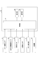
- the air purifying device 10 includes a cleaning unit 20, a circulation unit 30, a detection unit 40, and a control device 50.
- the cleaning unit 20, the circulation unit 30, and the detection unit 40 are installed in the indoor space (indoor space) S of the vehicle 12, and the main body of the control device 50 is outside the space S and inside the vehicle 12. It is provided. Further, the cleaning unit 20 and the circulation unit 30 are provided in the device main body 11 of the air purifying device 10.
- the device main body 11 has a casing provided with an internal space for accommodating the cleaning unit 20 and the circulation unit 30.
- the internal space constitutes a ventilation path for circulating the inhaled air in a predetermined direction.
- a casing formed in a tubular shape, a rectangular parallelepiped shape, or the like can be used as the casing of the device main body 11.
- the cleaning unit 20 purifies the air in the space S, and has a purifying substance generating unit 21 and a dust collecting filter 22.
- the cleaning unit 20 includes a purification substance generating unit 21 and a dust collecting filter 22 in this order along the air blowing direction.
- the purifying substance generating unit 21 generates ozone in the air using oxygen in the air taken in by the blower 32 described later as a raw material, and functions as an ozone generating unit. Then, the purifying substance generating unit 21 is electrically connected to the control unit 51 (see FIG. 2) described later of the control device 50, and is controlled by the control unit 51 (see FIG. 2).
- the purifying substance generating unit 21 can be of any type as long as it can generate ozone.
- a discharge type one in which the discharge electrode and the counter electrode are alternately arranged in a state of facing each other can be used. In this discharge type, when a voltage is applied to both electrodes, a discharge occurs between both electrodes.
- oxygen contained in the air is activated, and a part of the dissociated or excited oxygen is changed to ozone (O 3 ).
- O 3 ozone
- Ozone oxidizes with the odorous components contained in the air to decompose and remove the odorous components.
- the odor component is, for example, toluene
- the odor component reacts with ozone and is decomposed into carbon dioxide (CO 2 ) and water (H 2 O), which are reaction products, as shown in the following formula (1).
- CO 2 carbon dioxide
- H 2 O water
- the amount of ozone generated (amount of ozone generated) in the purifying substance generating unit 21 can be controlled (increase / decrease, start / stop, etc.) by adjusting the amount of discharge by the control unit 51 (see FIG. 2) described later.
- the dust collecting filter 22 is provided on the downstream side in the air flow direction from the purifying substance generating unit 21.
- the dust collecting filter 22 collects solid matter such as soot and dust in the air.
- the dust collecting filter 22 may be any as long as it can collect soot and the like in the air.
- a non-woven fabric made of fine metal wires, natural fibers or synthetic fibers formed in a pleated shape can be used.
- the circulation unit 30 has an intake port 31, a blower 32, and an exhaust port 33.
- the intake port 31 is for sucking the air in the space S into the inside of the device main body 11.
- the intake port 31 is formed in a slit shape on the side surface of the device main body 11.
- the intake port 31 may be formed on the upper surface or the lower surface of the device main body 11.
- the blower 32 is provided on the upstream side in the air flow direction with respect to the purifying substance generating portion 21 in the apparatus main body 11 and in the vicinity of the intake port 31. Then, the blower 32 is electrically connected to the control unit 51 (see FIG. 2) of the control device 50, and is controlled by the control unit 51 (see FIG. 2).
- the blower 32 for example, an axial fan that blows air in the rotation axis direction by propeller-shaped blades can be used.
- the blower 32 includes a motor (not shown) and a plurality of blades fixed to the rotating shaft of the motor.
- the blower 32 is supplied with power from an external power source, and the motor is driven to rotate the blades to suck air into the internal space of the apparatus main body 11 and purify the sucked air into the purifying substance generating unit 21 and the dust collecting filter. It is passed in the order of 22, and is discharged from the exhaust port 33 into the space S.
- the rotation speed of the blower 32 is controlled by a control unit 51 (see FIG. 2) described later.
- the exhaust port 33 is for discharging the air (clean air) purified by the cleaning unit 20 in the apparatus main body 11 to the space S in the vehicle.
- the exhaust port 33 is formed in a slit shape on the side surface of the device main body 11.
- the intake port 31 may be formed on the upper surface of the device main body 11.
- the detection unit 40 includes a purifying substance concentration sensor 41 which is a purifying substance concentration measuring unit, a reaction product concentration sensor 42 which is a reaction product concentration measuring unit, an odor sensor 43 which is an odor measuring unit, and a human sensing sensor which is a human detecting unit. Has 44. Each of these sensors is provided in the space S. Further, the detection unit 40 is electrically connected to the control unit 51 (see FIG. 2) of the control device 50, and transmits each detection signal to the control unit 51 (see FIG. 2).
- the purifying substance concentration sensor 41 measures the ozone concentration of the air in the space S, and functions as an ozone concentration sensor.
- a semiconductor type sensor or the like including a semiconductor element can be used as the purifying substance concentration sensor 41.
- ozone is adsorbed on the surface of the semiconductor element and the resistance value of the semiconductor element changes, so that the ozone concentration is measured.
- the purifying substance concentration sensor 41 is preferably provided at a position close to the intake port 31 in the space S.
- the position closer to the intake port 31 is easier to measure the ozone concentration in the state after the ozone released into the space S reacts with the odor component than the position closer to the exhaust port 33. Therefore, the ozone concentration contained in the air in the space S can be stably measured.
- the purifying substance concentration sensor 41 may be installed at a position far from the device main body 11 in the space S.
- the reaction product concentration sensor 42 measures the concentration (moisture concentration (humidity)) of water, which is one of the reaction products generated when the odorous component is decomposed by ozone.
- concentration moisture concentration (humidity)
- a known water concentration meter (moisture meter) or the like can be used as the reaction product concentration sensor 42.
- the type of the moisture concentration meter is not limited, and as the moisture concentration meter, for example, a polymer capacitance type humidity sensor or the like can be used.
- the reaction product concentration sensor 42 may be provided at a position where the water concentration in the space S can be measured.
- the odor sensor 43 measures the concentration of the odor component in the space S.
- a semiconductor type sensor or the like using a metal oxide semiconductor such as tin oxide or zinc oxide can be used as the odor sensor 43.
- oxygen adsorbed on the surface of a semiconductor element reacts with an odor component (surface reaction), and oxygen is released, so that the resistance value of the semiconductor element changes. From this change in resistance value, the concentration of odorous components in the air is measured.
- the odor sensor 43 may be of a type other than the semiconductor type.
- the person detection sensor 44 detects the presence or absence of a person in the space S.
- the human detection sensor 44 for example, an infrared sensor that detects the heat of an animal such as a person or a pet with infrared rays can be used.
- the human detection sensor 44 is preferably used as the human detection unit, but any sensor that can detect the presence or absence of a person or an animal may be used.
- the control device 50 includes a control unit 51 which is a main body, an operation unit 52 connected to the control unit 51, and a display unit 53.
- the control unit 51 is provided outside the space S and inside the vehicle 12, and the operation unit 52 and the display unit 53 are provided inside the space S.
- the control unit 51 is connected to each member constituting the air purifying device 10 such as the purifying substance generating unit 21 and the blower 32, and the display unit 53 in a controllable manner.
- the control unit 51 has a storage means for storing a control program and various storage information, and a calculation means for operating based on the control program.
- the control unit 51 is realized by the arithmetic means reading and executing a control program or the like stored in the storage means.
- the control unit 51 receives the measurement result from the detection unit 40.
- the control unit 51 controls the amount of ozone generated by the purifying substance generation unit 21 and the rotation speed of the blower 32 based on the measurement result of the detection unit 40.
- the control unit 51 has an ozone concentration measured by the purifying substance concentration sensor 41, a water concentration measured by the reaction product concentration sensor 42, and an odor component concentration in the space S measured by the odor sensor 43. And the signal of the detection result of the presence or absence of the person detected by the person detection sensor 44 is received.
- the control unit 51 calculates the ozone concentration, the water concentration, or the concentration of the odorous component in the air based on the signals received from these sensors, determines the presence or absence of a person, and supplies ozone to the purifying substance generating unit 21.
- a signal to be generated or a signal to rotate the blower 32 is output to the blower 32.
- the ozone generation amount or the air blowing amount is adjusted.
- the control unit 51 controls the purifying substance generating unit 21 to control the amount of ozone generated when the amount of increase in water concentration per unit time becomes equal to or less than a predetermined value.
- the control unit 51 determines the relationship between the amount of ozone generated by the purifying substance generation unit 21 and the volume of the space S, and the amount of increase in the concentration of reaction products (for example, water, CO 2, etc.) per unit time. It may be stored in a storage means in advance. In the present embodiment, it is preferable that the storage means stores the relationship between the amount of ozone generated by the purifying substance generating unit 21 and the volume of the space S, and the amount of increase in the water concentration per unit time. In this case, the control unit 51 compares the stored value stored in the storage means with the actually measured value measured by the purifying substance concentration sensor 41, and the amount of increase in the water concentration in the space S per unit time. Can be determined whether or not is less than or equal to a predetermined value.
- the control unit 51 controls the purifying substance generating unit 21 and the blower 32 to change the operating state of the air purifying device 10 to a ventilation mode, a purifying substance regular mode (hereinafter, referred to as an ozone regular mode in the present embodiment) and a purifying substance. It can be controlled to any of three operation modes of fumigation mode (hereinafter, referred to as ozone fumigation mode in this embodiment).
- the ventilation mode is an operation mode in which the air sucked into the device main body 11 is discharged from the inside of the device main body 11 into the space S without generating ozone in the purifying substance generating unit 21.
- the control unit 51 stops the operation of the purifying substance generating unit 21 and controls so that only the blower 32 is operated.
- the purifying substance generating unit 21 In the ozone regular mode, the purifying substance generating unit 21 generates low-concentration ozone, and the cleaning unit 20 uses the low-concentration ozone to clean the clean air together with the low-concentration ozone from the inside of the apparatus main body 11 into the space S. This is the operation mode for discharging.
- the control unit 51 operates the blower 32 and controls the purifying substance generation unit 21 to generate low-concentration ozone.
- the purifying substance generating unit 21 In the ozone fumigation mode, the purifying substance generating unit 21 generates high-concentration ozone, and the cleaning unit 20 uses the high-concentration ozone to clean the clean air together with the high-concentration ozone from the inside of the apparatus main body 11 to the space S. This is the operation mode for discharging.
- the control unit 51 operates the blower 32 and controls the purifying substance generation unit 21 to generate a high concentration of ozone.
- the first method is a method in which the amount of ozone generated by the purifying substance generating unit 21 is changed to keep the amount of air blown by the blower 32 constant.
- the second method is a method of varying the amount of air blown by the blower 32 while keeping the amount of ozone generated by the purifying substance generating unit 21 constant.
- the third method is a method of varying both the amount of ozone generated by the purifying substance generating unit 21 and the amount of air blown by the blower 32.
- the low ozone concentration means a concentration in which the ozone concentration is in the range of a standard value or less that is safe for the human body, and is 0.1 ppm or less, preferably 0.05 ppm or less.
- a high ozone concentration means that the ozone concentration is higher than the standard value that is safe for the human body, and the higher the concentration is preferable in order to efficiently decompose the odorous components, but the effect on the human body is affected. I am concerned. Therefore, it is preferable to perform the ozone fumigation mode using high-concentration ozone after confirming with the human detection sensor 44 that no person, pet, or the like is in the space S in the vehicle.
- the operation unit 52 is arranged in the space S, and is a signal for controlling the presence / absence of ozone generation and the amount of ozone generated in the purifying substance generation unit 21, the presence / absence of operation of the blower 32, the rotation speed thereof, and the like by an external operation. Has a function of transmitting to the control unit 51.
- the display unit 53 is arranged in the space S, and the presence / absence and amount of ozone generated in the purifying substance generating unit 21, the presence / absence of operation of the blower 32 and its rotation speed, and the ozone concentration measured by the purifying substance concentration sensor 41. It has a function of displaying the water concentration measured by the reaction product concentration sensor 42, the concentration of the odor component in the space S measured by the odor sensor 43, the presence or absence of a person detected by the human sensing sensor 44, and the like. In addition, the display unit 53 displays the end of the air cleaning method, which will be described later.
- the operation operation of the air purifier 10 having the above configuration will be described.
- the control unit 51 is energized and the operation of the air purifier 10 starts.
- the operator selects the operation mode from the ventilation mode, the ozone regular mode, or the ozone fumigation mode on the operation unit 52. First, a case where the ventilation mode is performed will be described.
- a signal for setting the operation mode to the ventilation mode is transmitted from the operation unit 52 to the control unit 51.
- the control unit 51 receives the signal of the operation unit 52 and outputs a signal for driving the blower 32 to the blower 32 to rotate the blades of the blower 32.
- the air in the space S is sucked into the apparatus main body 11 from the intake port 31.
- the air sucked into the main body 11 of the apparatus passes through the purifying substance generating unit 21, and the dust collecting filter 22 removes solid matter such as soot and dust in the air.
- the air from which solids have been removed is also called clean air.
- the clean air that has passed through the dust collection filter 22 is pressure-fed by the blower 32 and discharged from the exhaust port 33 into the space S.
- the clean air discharged from the exhaust port 33 into the space S diffuses in the space S and is mixed with the air containing the odor component to become the air containing the odor component.
- Air circulates due to natural convection in space S. A part of the air circulating in the space S is sucked into the device main body 11 from the intake port 31, and is cleaned again by the air purifying device 10. By repeatedly cleaning the air in the space S with the air purifying device 10, the air in the space S becomes air having a low concentration of solid matter such as soot and dust.
- the operation mode is set to the ozone regular use mode.
- the operation unit 52 transmits a signal to the control unit 51 to change the operation mode to the ozone normal mode.
- the control unit 51 receives the signal of the operation unit 52 and outputs a signal for driving the blower 32 to the blower 32 to rotate the blades of the blower 32 and generate a signal for generating low-concentration ozone as a purifying substance.
- the purifying substance generating unit 21 is operated.
- the air sucked into the apparatus main body 11 from the intake port 31 reaches the purifying substance generating section 21, the air passes through the purifying substance generating section 21 and low-concentration ozone is mixed in the air.
- the air containing low-concentration ozone that has passed through the purifying substance generating section 21 is pumped by the blower 32 after the solid matter such as dust in the air is removed by the dust collecting filter 22, and is sent from the exhaust port 33 into the space S. It is discharged to the air and diffuses in the space S.
- the air containing ozone diffuses in the space S from the purifying substance generating unit 21, odorous components and the like contained in the air are decomposed and removed by an oxidative reaction with ozone. As a result, the air is deodorized and sterilized. Further, when not only the odorous component contained in the air but also the odorous component adhering to the seat or wall in the vehicle comes into contact with ozone, it is deodorized and sterilized by oxidizing reaction with ozone. On the other hand, the ozone mixed in the air by the purifying substance generating unit 21 disappears by reacting with the odorous component in the air.
- air deodorized and sterilized by ozone is also called clean air.
- the clean air includes not only the case where the air does not completely contain the odor component but also the case where the odor component is contained in a very small amount.
- the clean air discharged from the exhaust port 33 into the space S diffuses in the space S and is mixed with the air containing the odor component to become the air containing the odor component.
- the air circulates in the space S. A part of the circulating air is sucked into the device main body 11 and cleaned again by the air purifying device 10. By repeatedly cleaning the air in the space S with the air purifying device 10, the air in the space S becomes deodorized and sterilized air having a low concentration of solid matter.
- the ozone concentration, water concentration, and odor component concentration in the air in the space S are measured by the purifying substance concentration sensor 41, the reaction product concentration sensor 42, and the odor sensor 43. These measurement results are sent to the control unit 51.
- the presence or absence of a person in the vehicle 12 is detected by the person detection sensor 44, and the detection result is sent to the control unit 51.
- the control unit 51 outputs a signal for controlling the purifying substance generating unit 21 and the blower 32, respectively, based on the detection results of each of these sensors.
- the ozone fumigation mode is the same as the ozone regular mode except that the control unit 51 outputs a signal to generate a high concentration ozone to the purifying substance generating unit 21 to generate a high concentration ozone from the purifying substance generating unit 21. Shows the operation.
- ozone fumigation mode ozone is consumed by reacting with the odor component while the odor component is present in the air, but the air sucked into the apparatus main body 11 is newly higher than the purifying substance generating unit 21. Concentration of ozone is supplied. Therefore, when the odorous component that reacts with ozone in the air disappears, the ozone concentration in the air rises at a constant rate. Ozone naturally decomposes and disappears in the process of air being released from the purifying substance generating unit 21 into the space S, but the decomposition rate is the rate at which ozone reacts with odorous components and decomposes. It is much lower than the supply rate of ozone supplied into the air from the purifying substance generator 21. Therefore, it is not necessary to particularly consider the decomposition rate of ozone when determining the increase or decrease of the ozone concentration.
- the ozone fumigation mode since high-concentration ozone that may affect the human body is used, it is desirable to start the operation after confirming that there are no people, pets, etc. in the space S by the human detection sensor 44. .. In addition, even after the ozone generation is stopped, the user is notified whether or not the vehicle can be boarded after the ozone concentration falls below the safe concentration, or the door lock is unlocked after the ozone concentration falls below the safe concentration. desirable.
- Air purification method> an example of an air purifying method for purifying air using the air purifying device 10 having the above configuration will be described with reference to FIGS. 3 and 4. Here, a case where the odor component is toluene will be described.
- FIG. 3 is a flowchart illustrating an air cleaning method
- FIG. 4 is a diagram showing an example of the relationship between time and the water concentration and the toluene concentration.
- the control unit 51 selects the ozone fumigation mode as the operation mode, operates the purification substance generation unit 21 and the blower 32, sucks the air in the space S, and the purification substance generation unit 21. To generate a high concentration of ozone in (step S11).
- the water concentration in the space S is measured by the reaction product concentration sensor 42 (concentration measurement step: step S12).
- the measurement result of the water concentration is sent to the control unit 51.
- control unit 51 calculates whether or not the amount of increase in the water concentration per unit time measured by the reaction product concentration sensor 42 is equal to or less than a predetermined value (step S13).
- the predetermined value means that the amount of increase in water concentration per unit time is, for example, 3.0% or less, and is preferably the same or about the same.
- the same degree means a range that allows an error of ⁇ 1.0%.
- the value of water concentration at the start of unit time ⁇ T the value of water concentration at the end of unit time ⁇ T.
- the ratio to the difference between the value of the water concentration at the start of the unit time ⁇ T can be used. ((Value of water concentration at the end of unit time ⁇ T)-(Value of water concentration at the start of unit time ⁇ T)) / (Value of water concentration at the start of unit time ⁇ T) ⁇ ⁇ ⁇ (I)
- the average value of the sum of the water concentration in the unit time ⁇ T the value of the water concentration in the middle time of the unit time ⁇ T, or the like can be used.
- step S13 when the amount of increase in water concentration per unit time exceeds a predetermined value (step S13: No), the control unit 51 keeps the purifying substance generating unit 21 in operation. Then, the control unit 51 measures the water concentration in the space S with the reaction product concentration sensor 42 (step S12), and calculates whether or not the amount of increase in the water concentration per unit time is equal to or less than a predetermined value (step S13). .. For a predetermined time from the start of operation of the purifying substance generating unit 21, ozone reacts with an odor component (toluene in this case) to generate a reaction product (water and CO 2 ), so that water, which is one of the reaction products, The concentration continues to increase.
- an odor component toluene in this case
- a high concentration of ozone is newly supplied to the air from the purifying substance generating unit 21. Therefore, ozone reacts with toluene to produce reaction products (CO 2 and water), and the water concentration increases from M1 to M2.
- reaction products CO 2 and water
- the lengths of the times T1 and T2, the degree of change in the concentration of toluene, and the degree of change in the water concentration depend on the concentration of toluene in the space S of the vehicle and the like.
- step S13 when the amount of increase in water concentration per unit time is equal to or less than a predetermined value (step S13: Yes), the control unit 51 stops the generation of high-concentration ozone in the purifying substance generating unit 21 (adjustment).
- Step S14 When a predetermined time elapses from the start of ozone generation and almost all the toluene existing in the space S is decomposed, the decomposition of toluene ends. As a result, since there is almost no substance that reacts with ozone in the space S, the concentration of the reaction product (CO 2 and water) hardly increases and becomes a predetermined value or less.
- the toluene that reacts with ozone is almost eliminated in the space S, so that the amount of increase in the water concentration per unit time is equal to or less than a predetermined value at the time T2. It becomes almost constant.
- the amount of increase in water concentration per unit time is less than or equal to the predetermined value even once, it can be determined that the amount of increase in water concentration per unit time is less than or equal to the predetermined value, but the present invention is not limited to this.
- a predetermined value for example, as shown in FIG. 5, the amount of increase in water concentration ⁇ C per unit time ⁇ T is continuously performed a plurality of times (for example,). (3 times or more), the case where they are almost the same can be used. In this case, it can be determined that the amount of increase in water concentration per unit time is equal to or less than a predetermined value.
- the amount of increase in water concentration per unit time is preferably constant. If the amount of increase in water concentration is constant, the control unit 51 can easily determine that the amount of increase in water concentration per unit time is equal to or less than a predetermined value, so that all the odorous components of S in the space have been removed. It is easier to detect things more reliably.
- the control unit 51 determines that the amount of increase in the water concentration per unit time measured by the reaction product concentration sensor 42 is equal to or less than a predetermined value, the height of the purification substance generation unit 21 is increased. The generation of concentrated ozone is stopped (forced termination) (see P3 at the time point in FIG. 4). As a result, the amount of ozone generated in the space S can be reduced.
- the generation of high-concentration ozone is changed to the generation of low-concentration ozone without stopping the purifying substance generating section 21 other than stopping the purifying substance generating section 21. Switch and gradually reduce the ozone concentration. Then, the ventilation mode may be finally switched, or the purifying substance generating unit 21 may be stopped to stop the generation of ozone.
- the purifying substance generating section 21 When the operation of the purifying substance generating section 21 is stopped, the supply of ozone from the purifying substance generating section 21 to the space S is stopped, so that the ozone newly generated in the space S disappears and almost all the toluene to be decomposed remains. Absent. Therefore, the water concentration in the space S becomes constant. Since the ozone in the space S is naturally decomposed, the ozone concentration in the space S gradually decreases.
- the air purifier 10 includes a reaction product concentration sensor 42 and a control unit 51.
- the control unit 51 controls the purifying substance generation unit 21 to control the ozone generation amount when the increase amount of the water concentration per unit time becomes equal to or less than a predetermined value.
- ozone generated from the purifying substance generating unit 21 is supplied into the space S, it decomposes odorous components (for example, toluene and the like) existing in the space S to generate water which is one of the reaction products.
- odorous components for example, toluene and the like
- the control unit 51 controls the purifying substance generating unit 21 and is supplied from the purifying substance generating unit 21. Control the amount of ozone generated. Therefore, since the air purifier 10 can more accurately determine the end of deodorization in the space S, it is possible to stop the generation of ozone at the optimum timing when the deodorization is completed.
- the air purifying device 10 can suppress the generation of excess ozone in the purifying substance generating unit 21, it is possible to efficiently remove the odor component while reducing the wasteful energy consumption. Therefore, according to the air purifier 10, it is possible to reduce discomfort to the user of the next vehicle, and it is possible to reduce unnecessary time required for deodorizing work while suppressing wasteful power consumption. be able to.
- the air purifier 10 can reduce the amount of excess ozone remaining in the space S by stopping the generation of ozone at the optimum timing, even if the odor sensor 43 is a semiconductor sensor, it can be reduced.
- the odor sensor 43 can stably measure the concentration of the odor component. For example, when the odor sensor 43 is a semiconductor sensor, if the ozone generated during deodorization exists in the space S of the vehicle, oxygen ions adsorbed on the surface of the semiconductor element increase, so that the odor sensor 43 It may reduce the measurement performance of the odorous component of 43.
- the odor sensor 43 may measure the concentration of the odor component to be small, and the concentration of the odor component may not be accurately measured. As a result, the operation of the purifying substance generating unit 21 may be stopped. In the present embodiment, it is possible to reduce the amount of excess ozone remaining in the space S, so even if the odor sensor 43 is a semiconductor sensor, oxygen ions that are excessively adsorbed on the surface of the semiconductor element of the odor sensor 43 The amount of is suppressed.
- the air purifying device 10 uses a semiconductor sensor for the odor sensor 43, it is possible to reduce the excess adsorption of ozone to the semiconductor surface of the semiconductor element of the odor sensor 43, so that the odor sensor 43 detects the odor component. It is possible to suppress the deterioration of the performance to be performed. Therefore, the air purifier 10 can stably measure the concentration of the odor component with the odor sensor 43 with high accuracy.
- the control unit 51 can determine in advance the amount of increase in water concentration per unit time, which is calculated based on the amount of ozone generated and the volume of the space S, as a predetermined value. By comparing the measured value with the predetermined value, the control unit 51 can easily determine whether or not the amount of increase in the water concentration in the space S per unit time has reached the predetermined value. This makes it easier for the control unit 51 to make a determination for controlling the purifying substance generating unit 21.
- the amount of increase in water concentration per unit time is preferably constant.
- “constant” means that the amount of increase in water concentration per unit time is almost zero.
- the amount of increase in water concentration is constant, it can be more reliably measured that all the odorous components in the space S have been removed. Therefore, by stopping (forced termination) the operation of the purifying substance generating unit 21 at the timing when the amount of increase in water concentration per unit time becomes constant, the amount of ozone generated in the space S can be reduced, and more. The generation of ozone can be stopped optimally. Therefore, according to the air purifier 10, the odor component can be removed more efficiently while further reducing the wasteful energy consumption.
- the air purifier 10 is controlled by the control unit 51 into one of three modes: ventilation mode, ozone regular mode, and ozone fumigation mode. As a result, the air purifying device 10 can appropriately purify the air according to the concentration of the odor component in the space S.
- the air purifier 10 preferably includes an odor sensor 43. By including the odor sensor 43, the air purifier 10 can detect the odor component in the space S.
- the air purifier 10 preferably includes a human detection sensor 44. By providing the air purifying device 10 with the human sensing sensor 44, it is possible to confirm whether or not a person exists in the space S. As a result, when the air purifier 10 is operating in the ozone fumigation mode, the air purifier 10 can stably perform the ozone fumigation mode in a state where no person is present in the space S.
- the air purifying device 10 preferably includes a purifying substance concentration sensor 41. By including the purifying substance concentration sensor 41, the air purifying device 10 can measure the concentration of ozone in the space S.
- the air purifying device 10 purifies the air in the space S inside the vehicle 12 .
- the air purifying device 10 purifies the air in the space S at the optimum timing. can do. Therefore, the air purifier 10 is suitably used not only as a vehicle 12 but also as an air purifier that is installed in, for example, a train, an airplane, a building, or the like to purify the air in those spaces. Can be done.
- the air purifier 10 deodorizes the partition space of the smoke separation room installed in the kitchen of a store, a public facility, the building space of a garbage collection place, the internal storage space of an air conditioner, a refrigerator, etc. It may be provided in a route or the like.
- the reaction product concentration sensor 42 provided in the space S is measures the moisture concentration as the concentration of response product, using a CO 2 concentration sensor for measuring the concentration of CO 2 You may.
- a CO 2 concentration sensor a known gas sensor such as a non-dispersive infrared (NDIR) type sensor can be used.
- both a sensor for measuring the water concentration and a sensor for measuring the CO 2 concentration may be provided.
- the device main body 11 having the cleaning unit 20 and the circulation unit 30 is installed in the space S inside the vehicle 12, but is not limited to this.
- the device main body 11 may be provided inside the vehicle 12 but outside the space S, and the intake port 31 and the exhaust port 33 of the circulation unit 30 may be opened toward the inside of the space S.
- the purifying substance generating unit 21 generates ozone as a purifying substance for purifying the odorous component, but any substance that can decompose the odorous component contained in the air to generate a reaction product may be used.
- an oxidizing agent such as hypochlorous acid (HClO) or hydrogen peroxide (H 2 O 2 ) may be generated.
- the reaction product concentration sensor 42 can use a hydrochloric acid concentration sensor capable of measuring the hydrochloric acid concentration in the air in the space S.
- the odorous component is represented as RH as in the following formula (2)
- the odorous component reacts with HClO to produce hydrochloric acid (HCl), which is a reaction product. Therefore, the reaction product concentration sensor 42 can detect hydrochloric acid using a hydrochloric acid concentration sensor that can measure the hydrochloric acid concentration in the air in the space S.
- the purifying substance concentration sensor 41 may use a hypochlorous acid concentration sensor capable of measuring the hypochlorous acid concentration in the air in the space S. it can.
- a measuring device including a fluorescent reagent that reacts with hypochlorous acid generated by the purifying substance generating unit 21 and emits light can be used.
- the fluorescent reagent provided in the purifying substance concentration sensor 41 emits light when it comes into contact with hypochlorous acid.
- the purifying substance concentration sensor 41 can stably measure the presence / absence of hypochlorous acid contained in the air in the space S and the concentration of hypochlorous acid according to the presence / absence of light emission and the light emission intensity of the fluorescent reagent. Further, as the purifying substance concentration sensor 41, in addition to the above-mentioned measuring device, a hydrochloric acid gas sensor using carbon nanotubes has a small size and high sensitivity, and can be preferably used.
- the purifying substance generating unit 21 and the blower 32 are incorporated together in the device main body 11, but they do not have to be incorporated together in the device main body 11.
- the blower 32 is provided on the upstream side of the purifying substance generating unit 21 in the apparatus main body 11 in the air flow direction, but on the downstream side of the purifying substance generating unit 21 in the air flow direction. It may be provided.
- the cleaning unit 20 includes the dust collecting filter 22, but when it is not necessary to collect solid matter such as soot and dust in the air, the cleaning unit 20 does not include the dust collecting filter 22. You may.
- the dust collecting filter 22 is used to collect solids such as soot and dust in the air, but it is sufficient if the solids such as soot and dust can be removed from the air.
- an electric dust collector may be used instead of the dust collector filter 22.
- An electrostatic precipitator is a device that applies a high voltage to air to charge dust and the like contained in the air and adsorb it on a dust collecting plate to remove it. By using the electrostatic precipitator, the maintenance cycle becomes longer than when the dust collector filter 22 is used, and the number of maintenances can be reduced.
- control device 50 is provided with the control unit 51 inside the vehicle 12 and outside the space S, and the operation unit 52 and the display unit 53 are provided inside the space S, but the present invention is not limited to this.
- the control device 50 may be provided in the device main body 11, or only the control unit 51 may be provided in the device main body 11. Further, the operation unit 52 and the display unit 53 of the control device 50 may be provided on the outside of the vehicle 12, or the control device 50 may be provided on the outside of the vehicle 12.
- Air purifier 20 Purifier 21 Purified substance generator 30 Circulator 32 Blower 40 Detector 41 Purified substance concentration sensor (Purified substance concentration measuring unit) 42 Reaction product concentration sensor (reaction product concentration part) 43 Odor sensor (odor measurement unit) 44 motion sensor (presence sensor) 51 Control unit S space
Landscapes
- Engineering & Computer Science (AREA)
- Health & Medical Sciences (AREA)
- Mechanical Engineering (AREA)
- Veterinary Medicine (AREA)
- General Health & Medical Sciences (AREA)
- Public Health (AREA)
- Animal Behavior & Ethology (AREA)
- Life Sciences & Earth Sciences (AREA)
- Epidemiology (AREA)
- Chemical & Material Sciences (AREA)
- Combustion & Propulsion (AREA)
- General Engineering & Computer Science (AREA)
- Disinfection, Sterilisation Or Deodorisation Of Air (AREA)
Priority Applications (1)
| Application Number | Priority Date | Filing Date | Title |
|---|---|---|---|
| JP2021527367A JP7183417B2 (ja) | 2019-06-27 | 2020-03-16 | 空気清浄装置及び空気清浄方法 |
Applications Claiming Priority (2)
| Application Number | Priority Date | Filing Date | Title |
|---|---|---|---|
| JP2019119788 | 2019-06-27 | ||
| JP2019-119788 | 2019-06-27 |
Publications (1)
| Publication Number | Publication Date |
|---|---|
| WO2020261668A1 true WO2020261668A1 (ja) | 2020-12-30 |
Family
ID=74061392
Family Applications (1)
| Application Number | Title | Priority Date | Filing Date |
|---|---|---|---|
| PCT/JP2020/011422 Ceased WO2020261668A1 (ja) | 2019-06-27 | 2020-03-16 | 空気清浄装置及び空気清浄方法 |
Country Status (2)
| Country | Link |
|---|---|
| JP (1) | JP7183417B2 (https=) |
| WO (1) | WO2020261668A1 (https=) |
Citations (5)
| Publication number | Priority date | Publication date | Assignee | Title |
|---|---|---|---|---|
| JP2004028433A (ja) * | 2002-06-25 | 2004-01-29 | Daikin Ind Ltd | 空気清浄機 |
| JP2005058463A (ja) * | 2003-08-12 | 2005-03-10 | Karumoa:Kk | オゾン脱臭方法 |
| JP2011056191A (ja) * | 2009-09-14 | 2011-03-24 | Kyushu Univ | 浮遊性有機化合物の分解方法および浮遊性有機化合物分解装置 |
| JP2019076481A (ja) * | 2017-10-25 | 2019-05-23 | ウシオ電機株式会社 | 光脱臭装置および光脱臭方法 |
| WO2019150735A1 (ja) * | 2018-02-02 | 2019-08-08 | アルプスアルパイン株式会社 | 空気清浄装置、及び空気清浄方法 |
-
2020
- 2020-03-16 JP JP2021527367A patent/JP7183417B2/ja active Active
- 2020-03-16 WO PCT/JP2020/011422 patent/WO2020261668A1/ja not_active Ceased
Patent Citations (5)
| Publication number | Priority date | Publication date | Assignee | Title |
|---|---|---|---|---|
| JP2004028433A (ja) * | 2002-06-25 | 2004-01-29 | Daikin Ind Ltd | 空気清浄機 |
| JP2005058463A (ja) * | 2003-08-12 | 2005-03-10 | Karumoa:Kk | オゾン脱臭方法 |
| JP2011056191A (ja) * | 2009-09-14 | 2011-03-24 | Kyushu Univ | 浮遊性有機化合物の分解方法および浮遊性有機化合物分解装置 |
| JP2019076481A (ja) * | 2017-10-25 | 2019-05-23 | ウシオ電機株式会社 | 光脱臭装置および光脱臭方法 |
| WO2019150735A1 (ja) * | 2018-02-02 | 2019-08-08 | アルプスアルパイン株式会社 | 空気清浄装置、及び空気清浄方法 |
Also Published As
| Publication number | Publication date |
|---|---|
| JP7183417B2 (ja) | 2022-12-05 |
| JPWO2020261668A1 (https=) | 2020-12-30 |
Similar Documents
| Publication | Publication Date | Title |
|---|---|---|
| JP7066755B2 (ja) | 空気清浄装置、及び空気清浄方法 | |
| AU671345B2 (en) | Environment decontaminating system having air cleaning and deodorizing function | |
| TWI281974B (en) | Ion generator and air conditioning apparatus | |
| JP5218308B2 (ja) | 脱臭機能再生装置 | |
| CN1665548A (zh) | 利用臭氧的空气净化除臭杀菌器 | |
| WO2007083573A1 (ja) | 脱臭機能再生装置および脱臭機能再生装置を備えた空気調和装置 | |
| KR20170065724A (ko) | 비열 플라즈마를 이용한 차량용 실내 공기 청정 장치 | |
| JP2014202421A (ja) | 空気調和機 | |
| TW201629403A (zh) | 空氣清淨機 | |
| JP2008167900A (ja) | 空気清浄装置 | |
| US20200009283A1 (en) | Deodorizing System | |
| KR100560054B1 (ko) | 오존을 이용한 공기청정 탈취 살균기 | |
| JPH09313585A (ja) | オゾン発生器付き空気清浄装置 | |
| JP2013022539A (ja) | 空気清浄機 | |
| JP7183417B2 (ja) | 空気清浄装置及び空気清浄方法 | |
| KR20110004617A (ko) | 고도산화공정을 이용한 고효율 탈취ㆍ공기살균 장치 및 그방법 | |
| JP2004150734A (ja) | 空気清浄装置 | |
| JP2008036168A (ja) | 脱臭装置 | |
| JP2004028433A (ja) | 空気清浄機 | |
| JP2008183326A (ja) | 脱臭装置 | |
| JPH0630198Y2 (ja) | 空気清浄脱臭器 | |
| JP3462942B2 (ja) | 空気清浄装置 | |
| JP7604744B2 (ja) | オゾン発生制御装置 | |
| EP4339521A1 (en) | Humidifier | |
| JP2002224205A (ja) | 空気清浄機及び空気清浄機の制御方法 |
Legal Events
| Date | Code | Title | Description |
|---|---|---|---|
| 121 | Ep: the epo has been informed by wipo that ep was designated in this application |
Ref document number: 20832254 Country of ref document: EP Kind code of ref document: A1 |
|
| ENP | Entry into the national phase |
Ref document number: 2021527367 Country of ref document: JP Kind code of ref document: A |
|
| NENP | Non-entry into the national phase |
Ref country code: DE |
|
| 122 | Ep: pct application non-entry in european phase |
Ref document number: 20832254 Country of ref document: EP Kind code of ref document: A1 |