WO2020255708A1 - 車載通信システム、車載通信装置及び送信周期算出方法 - Google Patents
車載通信システム、車載通信装置及び送信周期算出方法 Download PDFInfo
- Publication number
- WO2020255708A1 WO2020255708A1 PCT/JP2020/021867 JP2020021867W WO2020255708A1 WO 2020255708 A1 WO2020255708 A1 WO 2020255708A1 JP 2020021867 W JP2020021867 W JP 2020021867W WO 2020255708 A1 WO2020255708 A1 WO 2020255708A1
- Authority
- WO
- WIPO (PCT)
- Prior art keywords
- message
- time
- delay time
- vehicle communication
- received
- Prior art date
- Legal status (The legal status is an assumption and is not a legal conclusion. Google has not performed a legal analysis and makes no representation as to the accuracy of the status listed.)
- Ceased
Links
Images





Classifications
-
- H—ELECTRICITY
- H04—ELECTRIC COMMUNICATION TECHNIQUE
- H04L—TRANSMISSION OF DIGITAL INFORMATION, e.g. TELEGRAPHIC COMMUNICATION
- H04L12/00—Data switching networks
- H04L12/28—Data switching networks characterised by path configuration, e.g. LAN [Local Area Networks] or WAN [Wide Area Networks]
- H04L12/40—Bus networks
- H04L12/40006—Architecture of a communication node
-
- H—ELECTRICITY
- H04—ELECTRIC COMMUNICATION TECHNIQUE
- H04L—TRANSMISSION OF DIGITAL INFORMATION, e.g. TELEGRAPHIC COMMUNICATION
- H04L12/00—Data switching networks
- H04L12/28—Data switching networks characterised by path configuration, e.g. LAN [Local Area Networks] or WAN [Wide Area Networks]
- H04L12/40—Bus networks
-
- H—ELECTRICITY
- H04—ELECTRIC COMMUNICATION TECHNIQUE
- H04L—TRANSMISSION OF DIGITAL INFORMATION, e.g. TELEGRAPHIC COMMUNICATION
- H04L12/00—Data switching networks
- H04L12/28—Data switching networks characterised by path configuration, e.g. LAN [Local Area Networks] or WAN [Wide Area Networks]
- H04L12/40—Bus networks
- H04L12/407—Bus networks with decentralised control
- H04L12/413—Bus networks with decentralised control with random access, e.g. carrier-sense multiple-access with collision detection [CSMA-CD]
-
- H—ELECTRICITY
- H04—ELECTRIC COMMUNICATION TECHNIQUE
- H04L—TRANSMISSION OF DIGITAL INFORMATION, e.g. TELEGRAPHIC COMMUNICATION
- H04L43/00—Arrangements for monitoring or testing data switching networks
- H04L43/08—Monitoring or testing based on specific metrics, e.g. QoS, energy consumption or environmental parameters
- H04L43/0852—Delays
- H04L43/0858—One way delays
-
- H—ELECTRICITY
- H04—ELECTRIC COMMUNICATION TECHNIQUE
- H04L—TRANSMISSION OF DIGITAL INFORMATION, e.g. TELEGRAPHIC COMMUNICATION
- H04L43/00—Arrangements for monitoring or testing data switching networks
- H04L43/16—Threshold monitoring
-
- H—ELECTRICITY
- H04—ELECTRIC COMMUNICATION TECHNIQUE
- H04L—TRANSMISSION OF DIGITAL INFORMATION, e.g. TELEGRAPHIC COMMUNICATION
- H04L67/00—Network arrangements or protocols for supporting network services or applications
- H04L67/01—Protocols
- H04L67/12—Protocols specially adapted for proprietary or special-purpose networking environments, e.g. medical networks, sensor networks, networks in vehicles or remote metering networks
-
- H—ELECTRICITY
- H04—ELECTRIC COMMUNICATION TECHNIQUE
- H04L—TRANSMISSION OF DIGITAL INFORMATION, e.g. TELEGRAPHIC COMMUNICATION
- H04L69/00—Network arrangements, protocols or services independent of the application payload and not provided for in the other groups of this subclass
- H04L69/28—Timers or timing mechanisms used in protocols
-
- H—ELECTRICITY
- H04—ELECTRIC COMMUNICATION TECHNIQUE
- H04L—TRANSMISSION OF DIGITAL INFORMATION, e.g. TELEGRAPHIC COMMUNICATION
- H04L12/00—Data switching networks
- H04L12/28—Data switching networks characterised by path configuration, e.g. LAN [Local Area Networks] or WAN [Wide Area Networks]
- H04L12/40—Bus networks
- H04L2012/40208—Bus networks characterized by the use of a particular bus standard
- H04L2012/40215—Controller Area Network CAN
-
- H—ELECTRICITY
- H04—ELECTRIC COMMUNICATION TECHNIQUE
- H04L—TRANSMISSION OF DIGITAL INFORMATION, e.g. TELEGRAPHIC COMMUNICATION
- H04L12/00—Data switching networks
- H04L12/28—Data switching networks characterised by path configuration, e.g. LAN [Local Area Networks] or WAN [Wide Area Networks]
- H04L12/40—Bus networks
- H04L2012/40267—Bus for use in transportation systems
- H04L2012/40273—Bus for use in transportation systems the transportation system being a vehicle
Definitions
- the present disclosure relates to an in-vehicle communication system and an in-vehicle communication device for transmitting and receiving messages via a common communication line, and also to a transmission cycle calculation method for calculating a transmission cycle of a message transmitted periodically.
- a vehicle is equipped with a plurality of devices such as an ECU (Electronic Control Unit). These plurality of in-vehicle devices are connected to each other via a communication line, exchange information by transmitting and receiving messages, and realize various functions of the vehicle by cooperation.
- the communication standard of CAN Controller Area Network
- CAN Controller Area Network
- Patent Document 1 proposes an in-vehicle network expansion device that can be expected to efficiently arbitrate communication between communication lines when the CAN communication lines arranged in the vehicle are divided into multiple systems.
- This in-vehicle network expansion device includes a circuit that arbitrates communication between communication lines based on the priority given to a message when a communication collision occurs between communication lines.
- Devices such as an ECU mounted on a vehicle often periodically transmit a message having predetermined information. Utilizing this, the device on the side of receiving the message calculates the transmission cycle for the received message and determines whether or not the calculated transmission cycle is correct, thereby determining the correctness of the received message. It is possible. However, message transmission by a plurality of in-vehicle devices may occur at the same time to cause message collision, and transmission of a low-priority message may be delayed due to arbitration processing. When the message transmission is delayed due to the arbitration process, it is difficult for the device that receives this message to calculate the transmission cycle, and the accuracy of the correctness determination of the message based on the transmission cycle may be lowered.
- the present disclosure has been made in view of such circumstances, and an object thereof is to provide an in-vehicle communication system, an in-vehicle communication device, and a transmission cycle calculation method capable of accurately calculating a message transmission cycle. To do.
- the in-vehicle communication system is an in-vehicle communication system in which a plurality of in-vehicle communication devices connected to a common communication line transmit and receive a message via the communication line, and the in-vehicle communication device on the message transmitting side is ,
- the delay time measuring unit that measures the delay time from the time when the message to be sent is first attempted to the time when the message is started to be transmitted, and the delay time measured by the delay time measuring unit are added to the message.
- the vehicle-mounted communication device on the receiving side of the message which has a granting unit for granting, has a reception time-pointing acquisition unit that acquires the time when the message from the transmitting-side vehicle-mounted communication device is received, and a delay given to the received message.
- a calculation unit that calculates the transmission cycle of the message based on the delay time acquisition unit that acquires the time and the delay time acquired by the reception time acquisition unit and the delay time acquisition unit for each of the two received messages. And have.
- the present application can be realized not only as a device such as an in-vehicle communication device provided with such a characteristic processing unit, but also as a communication method in which the characteristic processing is a step, or the step is executed on a computer. It can be realized as a computer program for making it. It can be realized as a semiconductor integrated circuit that realizes a part or all of these devices, or can be realized as another device or system including these devices.
- the in-vehicle communication system is an in-vehicle communication system in which a plurality of in-vehicle communication devices connected to a common communication line transmit and receive a message via the communication line, and is in-vehicle on the message transmitting side.
- the communication device measures a delay time measuring unit that measures the delay time from the time when the message to be transmitted is first attempted to the time when the message is started to be transmitted, and a delay time measured by the delay time measuring unit.
- the in-vehicle communication device on the receiving side of the message has a receiving unit for acquiring the time when the message is received from the in-vehicle communication device on the transmitting side, and the receiving unit for acquiring the time when the message is received.
- the transmission cycle of the message is calculated based on the delay time acquisition unit that acquires the delayed time and the delay time acquired by the reception time acquisition unit and the delay time acquisition unit for each of the two received messages. It has a calculation unit to be used.
- the delay time from the time when the in-vehicle communication device on the transmitting side first tries to send the message to the time when the transmission of this message is actually started is given to this message.
- the message transmitted from the in-vehicle communication device on the transmitting side is received by the in-vehicle communication device on the receiving side connected to the common communication line.
- the in-vehicle communication device on the receiving side acquires the reception time point of the received message and also acquires the delay time given to the received message.
- the in-vehicle communication device on the receiving side acquires the reception time point and the delay time for each of the two messages received before and after in chronological order, and calculates the message transmission cycle based on the acquired information.
- the in-vehicle communication device on the transmitting side adds a delay time to the message and transmits it, and the in-vehicle communication device on the receiving side acquires the delay time from the message and calculates the transmission cycle, so that the in-vehicle communication device on the transmitting side mediates.
- the in-vehicle communication device on the receiving side can calculate the message transmission cycle in consideration of the delay in message transmission caused by the processing or the like. Therefore, the in-vehicle communication device on the receiving side can accurately calculate the message transmission cycle.
- the calculation unit calculates, as the transmission cycle, the time difference between the time when the previously received message goes back by the delay time from the reception time and the time when the later received message goes back by the delay time from the reception time. Is preferable.
- the time point that goes back by the delay time from the time when the message is received is the time point when the transmission of this message is first attempted. Therefore, the in-vehicle communication device on the receiving side calculates the time difference between the time when the previously received message goes back by the delay time from the reception time and the time when the later received message goes back by the delay time from the reception time, and calculates this time difference. Set as the message transmission cycle. Since the in-vehicle communication device on the receiving side can calculate the transmission cycle of the message based on the time when the in-vehicle communication device on the transmitting side first attempts to send the message, the transmission cycle of the message can be calculated accurately. it can.
- the in-vehicle communication device on the receiving side determines whether the received message is a message transmitted periodically or a message transmitted aperiodically based on the transmission cycle calculated by the calculation unit. It is preferable to have a periodic message determination unit for determination.
- the in-vehicle communication device on the receiving side transmits the received message periodically or aperiodically. Is determined.
- the in-vehicle communication device on the receiving side calculates, for example, the time difference at the time of transmission from the message received immediately before each time the message is received, and the calculated time difference falls within the error range with respect to the previously calculated transmission cycle. In this case, it can be determined that the received message is transmitted periodically.
- the in-vehicle communication device on the receiving side determines that the received message is transmitted aperiodically. be able to.
- the message determined to be aperiodic may be, for example, a message transmitted by event driving, an illegal message by an illegal device, or the like.
- the plurality of in-vehicle communication devices include an in-vehicle communication device having the delay time measuring unit and the imparting unit, and an in-vehicle communication device having the delay time measuring unit and the imparting unit. ..
- a vehicle-mounted communication device that transmits a message with a delay time and a message that is transmitted without a delay time are transmitted to a plurality of vehicle-mounted communication devices connected to a common communication line.
- In-vehicle communication devices may be included. That is, in the in-vehicle communication system, it is possible to mix a message with a delay time and a message without a delay time.
- a function of imparting a delay time to an in-vehicle communication device that is required to accurately determine a message transmission cycle may be added to an in-vehicle communication system having a conventional configuration that does not assign a delay time. Therefore, it is possible to facilitate the introduction of the configuration of the in-vehicle communication system of this embodiment into a conventional vehicle.
- Identification information for identifying the message is added to the message, and the in-vehicle communication device on the receiving side assigns a delay time to the message based on the identification information given to the received message. It is preferable to have a grant determination unit for determining whether or not the presence is present.
- the message sent and received by the in-vehicle communication device is given identification information for identifying this message.
- the message identification information can be, for example, CAN-ID in the CAN communication standard.
- the communication of this aspect is not limited to the communication standard of CAN, and various communication standards such as FlexRay or Ethernet (registered trademark) can be adopted.
- the in-vehicle communication device on the receiving side determines whether or not a delay time is added to this message based on the identification information of the received message. As a result, even when a message with a delay time and a message without a delay time are mixed, the in-vehicle communication device on the receiving side can calculate the message transmission cycle. ..
- the in-vehicle communication device is an in-vehicle communication device that is connected to a common communication line together with other in-vehicle communication devices and transmits / receives a message via the communication line, and transmits a message to be transmitted.
- a receiving unit that receives a message with a delay time from the time when the first attempt is made to the time when the transmission of the message is started, a receiving unit that acquires the time when the receiving unit receives the message, and a receiving unit that receives the message.
- a delay time acquisition unit that acquires the delay time given to the message, and a delay time acquired by the reception time acquisition unit and the delay time acquisition unit for each of the two received messages. It is provided with a calculation unit for calculating the transmission cycle.
- the message transmission cycle can be calculated accurately as in the aspect (1).
- the transmission cycle calculation method is a transmission cycle calculation method for calculating the transmission cycle of a message transmitted / received via the communication line by a plurality of in-vehicle communication devices connected to a common communication line.
- the in-vehicle communication device on the sending side of the message measures the delay time from the time when the in-vehicle communication device to send the message first tries to send the message to the time when the transmission of the message is started, and assigns the measured delay time to the message. Then, the in-vehicle communication device on the receiving side of the message acquires the time when the in-vehicle communication device on the transmitting side receives the message, acquires the delay time given to the received message, and for each of the two received messages.
- the transmission cycle of the message is calculated based on the time of acquisition and the delay time.
- the message transmission cycle can be calculated accurately as in the aspect (1).
- FIG. 1 is a block diagram showing a configuration of an in-vehicle communication system according to the present embodiment.
- the in-vehicle communication system according to the present embodiment is configured to include a plurality of ECUs 2 mounted on the vehicle 1.
- Each of the plurality of ECUs 2 is connected to a communication line 4 arranged in the vehicle 1, and can send and receive messages via the communication line 4.
- the plurality of ECUs 2 transmit and receive messages according to the CAN communication standard.
- the communication line 4 is called a CAN bus, and several to a dozen or more ECUs 2 can be connected to one communication line 4.
- the vehicle 1 may be provided with a plurality of communication lines 4, and in this case, a device such as a gateway that relays a message between the communication lines 4 is mounted on the vehicle.
- a device such as a gateway that relays a message between the communication lines 4 is mounted on the vehicle.
- the number of ECUs 2 included in the in-vehicle communication system, the number of communication lines 4, the connection mode of the devices, the network configuration, and the like are not limited to those shown in the drawings.
- the ECU 2 includes, for example, an ECU that controls the operation of the engine of the vehicle 1, an ECU that controls the lock / unlock of the door, an ECU that controls the on / off of the light, an ECU that controls the operation of the airbag, and ABS (Antilock).
- Various ECUs such as an ECU that controls the operation of the Brake System) may be included.
- the ECU 2 is mentioned as an in-vehicle communication device that transmits / receives a message via the communication line 4, but the in-vehicle communication device is not limited to these.
- CANID For messages that comply with CAN communication standards, identification information called CANID is stored in the beginning area of the message called arbitration field.
- the CANID is information indicating the type of data included in this message and the priority of this message. The smaller the value of CANID, the higher the priority of the message.
- arbitration arbitration
- CANID is a value determined by the designer at the design stage of the vehicle 1, the in-vehicle communication system, the ECU 2, or the like.
- the ECU 2 adds information on the delay time generated by the arbitration process to the message and transmits it.
- the ECU 2 receives the message reception time (time point) and the time (time point) at which the transmission source ECU 2 first attempts to transmit this message based on the delay time given to this message. That is, if there is no delay due to the arbitration process, the transmission time (transmission time point) at which the transmission source ECU 2 can transmit this message can be calculated.
- each ECU 2 repeatedly transmits a message at a predetermined cycle.
- the transmission cycle is predetermined for each ECU 2 or for each message type (that is, for each CANID), for example.
- the ECU 2 that has received the message has the message from the previous message transmission time to the current message based on the reception time and delay time of the received message and the reception time and delay time of the previous received message having the same CANID as this received message. Calculate the time difference until the transmission time. The calculation of this time difference corresponds to the process of calculating the transmission cycle of this message.
- the ECU 2 calculates the transmission cycle of this message each time a message is received.
- the ECU 2 compares the calculation result of the transmission cycle of this time with the calculation result of the transmission cycle up to the previous time, and when the transmission cycle of this time is significantly different from the transmission cycle of the previous time, the received message of this time is assumed. Judge that it is not a periodic message to be executed.
- the message determined by the ECU 2 to be not a periodic message is regarded as an invalid message and discarded.
- the aperiodic message may be processed as a legitimate message such as an event message.
- FIG. 2 is a block diagram showing a configuration of the ECU 2 according to the present embodiment.
- the ECU 2 according to the present embodiment includes a processing unit (processor) 21, a storage unit (storage) 22, an input / output unit (I / O) 23, a CAN controller 24, and the like.
- the processing unit 21 reads and executes the program 22a stored in the storage unit 22 to perform various processes such as control processing of the vehicle 1.
- the processing unit 21 gives a message to be transmitted to the CAN controller 24 and instructs the CAN controller 24 to transmit this message. Further, in the present embodiment, the processing unit 21 performs a process of calculating the transmission cycle of the received message.
- the storage unit 22 is configured by using a non-volatile memory element such as a flash memory or an EEPROM (Electrically Erasable Programmable Read Only Memory).
- the storage unit 22 stores various programs executed by the processing unit 21 and various data required for processing by the processing unit 21.
- the storage unit 22 stores the program 22a executed by the processing unit 21.
- the program 22a may be written in the storage unit 22 at the manufacturing stage of the ECU 2, for example.
- the ECU 2 may acquire what is distributed by a remote server device or the like by communication.
- the ECU 2 may read the program 22a recorded on a recording medium such as a memory card or an optical disk and store it in the storage unit 22.
- the writing device may read out what is recorded on the recording medium and write it in the storage unit 22 of the ECU 2.
- the program 22a may be provided in a mode of distribution via a network, or may be provided in a mode recorded on a recording medium.
- the input / output unit 23 for example, devices such as a sensor 5a and an actuator 5b are connected via a signal line or the like.
- the input / output unit 23 samples and acquires a signal input from an input device such as a sensor 5a, and gives the acquired information to the processing unit 21. Further, the input / output unit 23 outputs a control signal corresponding to the control command when the processing unit 21 gives a control command to the controlled target device such as the actuator 5b.
- the ECU 2 does not need to perform both input and output, and may be configured to perform only input or output, and may be configured not to perform either input or output.
- the CAN controller 24 performs processing related to sending and receiving a message via the communication line 4.
- the CAN controller 24 can be configured as, for example, one IC (Integrated Circuit).
- the CAN controller 24 is connected to a communication line 4 arranged in the vehicle 1 and transmits / receives a message in accordance with the CAN communication standard with another ECU 2 via the communication line 4.
- the CAN controller 24 converts a transmission message given by the processing unit 21 into an electric signal according to the CAN communication standard and outputs the message to the communication line 4, thereby transmitting the message to the other ECU 2.
- the CAN controller 24 receives a message from another ECU 2 by sampling and acquiring the potential of the communication line 4, and gives the received message to the processing unit 21.
- the CAN controller 24 includes a transmission processing unit 24a, a delay time measuring unit 24b, a delay time imparting unit 24c, a reception processing unit 24d, a reception time acquisition unit 24e, a delay time acquisition unit 24f, and the like. ..
- the transmission processing unit 24a performs a process of transmitting this message to the other ECU 2 by outputting the message to the communication line 4.
- the transmission processing unit 24a performs arbitration processing when the message transmission of the other ECU 2 is performed at the same time.
- the transmission processing unit 24a transmits a message when the transmission right is acquired by the arbitration process.
- the delay time measurement unit 24b performs a process of measuring the time when the message transmission is delayed because the transmission right cannot be acquired by the arbitration process.
- the delay time measuring unit 24b measures the delay time using a counter.
- the delay time measuring unit 24b starts timing the counter when, for example, a message to be transmitted and a transmission instruction are given from the processing unit 21. After that, the delay time measuring unit 24b acquires the value of the counter at the time when the transmission right is acquired by the arbitration process, and sets this value as the delay time. For example, when the value of the counter is 100 and the period of the clock that operates the counter is 1 ⁇ sec, the actual delay time is 100 ⁇ sec. In the present embodiment, it is assumed that the value of the clock period of the counter is known to the plurality of ECUs 2, and the value of this counter is treated as the delay time.
- the delay time giving unit 24c performs a process of adding the delay time (corresponding counter value) measured by the delay time measuring unit 24b to the transmitted message.
- the delay time assigning unit 24c stores the delay time in a part of the data field of the message according to the communication standard of CAN, for example.
- the reception processing unit 24d performs a process of receiving a message transmitted from another ECU 2.
- the reception processing unit 24d receives a message by repeatedly sampling the potential of the communication line 4, and gives the received message to the processing unit 21.
- the reception time acquisition unit 24e performs a process of acquiring the time when the reception processing unit 24d receives a message from another ECU 2.
- the CAN controller 24 has a timer function for measuring the current time.
- the time measured by the CAN controller 24 may be an absolute time shared with other devices, or may be a relative time used only by the own device.
- the timer function is realized by a counter, and by operating the counter at the same time as the CAN controller 24 is started, the relative time from the start can be measured by the counter.
- the reception time acquisition unit 24e acquires the reception time of the message by acquiring the value of the counter of the timer function at the timing when the message is received.
- the delay time acquisition unit 24f performs a process of acquiring information on the delay time given to the received message.
- the delay time information is stored in a part of the data field of the message.
- the delay time acquisition unit 24f extracts and acquires the delay time information from a predetermined location in the data field of the received message.
- the CAN controller 24 gives information such as the content of the message received by the reception processing unit 24d, the reception time acquired by the reception time acquisition unit 24e, and the delay time acquired by the delay time acquisition unit 24f to the processing unit 21.
- the processing unit 21 is provided with a transmission cycle calculation unit 21a.
- the transmission cycle calculation unit 21a is a software-like functional block realized by the processing unit 21 executing the program 22a stored in the storage unit 22.
- the transmission cycle calculation unit 21a may be realized as a hardware-like functional block.
- each time the CAN controller 24 receives a message it gives information such as the content of this message, the reception time, and the delay time to the processing unit 21.
- the transmission cycle calculation unit 21a of the processing unit 21 calculates the transmission cycle of this message by calculating the time difference between the received message and the previously received message. Perform the processing. Therefore, the transmission cycle calculation unit 21a stores the reception time and delay time information (or the message transmission time information calculated from the reception time and delay time) of the previously received message. ing.
- the transmission cycle calculation unit 21a calculates the transmission cycle of this message based on the reception time and delay time of the previous received message and the reception time and delay time of the current received message.
- a certain ECU ⁇ periodically transmits a message M ⁇ , and the transmission cycle of this message is T ⁇ . That is, in the ECU ⁇ , a transmission message and a transmission instruction are given from the processing unit 21 to the CAN controller 24 in a cycle T ⁇ .
- the ECU ⁇ receives the message M ⁇ transmitted by the ECU ⁇
- the time (message generation time) t ⁇ 0 at which the transmission instruction is given in the ECU ⁇ can be calculated by using the following equation (1).
- t ⁇ 0 t ⁇ 0-d0 ...
- T ⁇ (t ⁇ 1-d1)-(t ⁇ 0-d0) ...
- the transmission interval T ⁇ calculated by the equation (2) corresponds to the transmission cycle T ⁇ of the message M by the ECU ⁇ .
- T ⁇ T ⁇ since there are errors in the clock signals of ECU ⁇ and ECU ⁇ , there is a possibility that there is a difference between T ⁇ and T ⁇ due to these errors. That is, T ⁇ T ⁇ .
- the CAN controller 24 may include the transmission cycle calculation unit 21a. In this case, the CAN controller 24 gives the calculation result of the transmission cycle to the processing unit 21.
- the processing unit 21 can determine the correctness of the received message based on the transmission cycle calculated by the transmission cycle calculation unit 21a. In the present embodiment, the processing unit 21 calculates the transmission cycle of the received message, but the CAN controller 24 may calculate the transmission cycle, and the CAN controller 24 may give the calculation result to the processing unit 21. In this case, the CAN controller 24 may determine the correctness of the received message based on the calculated transmission cycle.
- FIG. 3 is a schematic diagram for explaining the configuration of a message transmitted by the ECU 2 in the in-vehicle communication system according to the present embodiment.
- the message according to the CAN communication standard includes an arbitration field, a control field, a data field, a CRC (Cyclic Redundancy Check) field, an ACK field, and the like.
- the CANID is stored in the arbitration field, and the delay time information is stored in a part of the data field.
- the maximum size of the message data field is 8 bytes.
- the size of the area for storing the delay time can be, for example, 2 bytes to 4 bytes.
- the size of the delay time is determined in advance at the design stage of the in-vehicle communication system or the like, for example, based on the maximum delay time. Assuming that the period of the clock signal for operating the counter for measuring the delay time is, for example, 2 ⁇ sec, the delay time of 2 bytes is about 130 msec at the maximum, and the delay time of 3 bytes is about 33 seconds at the maximum.
- the maximum delay time of 4 bytes is about 67 seconds.
- the CAN controller 24 starts transmitting the message by outputting the message given from the processing unit 21 to the communication line 4 in order from the MSB (Most Significant Bit) side, that is, the arbitration field side.
- the CAN controller 24 starts measuring the delay time by the counter.
- the arbitration process is performed from the start of message transmission to the completion of transmission of the arbitration field, and when the transmission of the last bit of the arbitration field is completed, the result of the arbitration process, that is, whether or not the message has the right to be transmitted is determined.
- the CAN controller 24 acquires the delay time measured by the counter and stores the acquired delay time in a predetermined place in the data field. After that, the CAN controller 24 transmits the control field, the data field, the CRC field, and the ACK field in this order, and completes the message transmission.
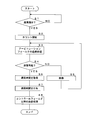
- FIG. 4 is a flowchart showing a procedure of message transmission processing performed by the CAN controller 24 according to the present embodiment.
- the transmission processing unit 24a of the CAN controller 24 determines whether or not a transmission instruction has been given together with a message to be transmitted from the processing unit 21 (step S1). When the transmission instruction is not given (S1: NO), the transmission processing unit 24a waits until the transmission instruction is given. When a transmission instruction is given (S1: YES), the delay time measuring unit 24b of the CAN controller 24 starts counting the delay time by the counter (step S2).
- the transmission processing unit starts transmission from the beginning of the transmission message, and first performs transmission processing of the arbitration field (step S3). At this time, the transmission processing unit 24a performs arbitration processing with the other ECU 2, and the presence or absence of the transmission right is determined by transmitting the final bit of the arbitration field. The transmission processing unit 24a determines whether or not it is possible to transmit its own message based on the result of the arbitration processing (step S4). When the message cannot be transmitted (S4: NO), the transmission processing unit 24a waits until the message transmission by the other ECU 2 is completed (step S5), returns the process to step S3, and transmits the message again. Try.
- the delay time measuring unit 24b acquires the delay time counted by the counter (step S6).
- the delay time assigning unit 24c of the CAN controller 24 assigns the delay time acquired in step S6 to a predetermined location in the data field of the transmitted message (step S7).
- the transmission processing unit 24a performs transmission processing for the control field and beyond of the transmission message (step S8), and ends the message transmission processing.
- FIG. 5 and 6 are schematic views for explaining a transmission cycle calculation method according to the present embodiment.
- FIG. 5 illustrates the relationship between the time (time point) and the time for one message.
- the time when the CAN controller 24 is given a transmission instruction from the processing unit 21 and first attempts to transmit a message is set as the transmission start time t0.
- the transmission of this message is made to stand by the message transmission of another ECU 2, and the message is retransmitted at the subsequent time t1.
- the transmission right of this message is determined at the time t2 when the last bit of the arbitration field is transmitted, and the delay time D at this point is given to a predetermined position in the data field of the message.
- the CAN controller 24 transmits the rest of the message and completes the transmission of the message at time t3. After that, at the time t4 when the message transmission cycle T elapses from the message transmission start time t0, the CAN controller 24 attempts to transmit the next message.
- the CAN controller 24 of the ECU 2 that receives this message sets the time t2 at which the transmission of this message is confirmed by the arbitration process as the reception time of this message.
- the CAN controller 24 completes the reception of the message at the subsequent time t3, and acquires the delay time D from a predetermined position in the data field of the received message.
- the CAN controller 24 gives information on the message reception time and the delay time to the processing unit 21.
- the processing unit 21 can calculate the time t0 that goes back from the message reception time t2 to the delay time D as the message transmission time t0.
- the processing unit 21 calculates the message transmission time in the same manner, and calculates the time difference between the transmission times of two consecutive received messages in chronological order.
- the transmission cycle T can be calculated.
- the delay time D given to the message by the CAN controller 24 of the ECU 2 on the transmitting side calculates the length of the message to be transmitted in advance, and the time until the transmission completion time t3 of this message, that is, (t3-t0). It may be the time corresponding to. In this case, the receiving ECU 2 sets the time when the message reception is completed as the message reception time.
- FIG. 6 shows an example of the reception time and the delay time for the four messages M0 to M3.
- the reception time, delay time, and the like in this figure are shown using counter values measured by a timer function counter included in the CAN controller 24 of the ECU 2 that has received the message.
- the message M0 is received at the reception time 1100, and 100 is added as a delay time.
- the message M1 is received at the reception time 2100, and 100 is added as a delay time.
- the message M2 is received at the reception time 3210, and 210 is added as a delay time.
- the message M3 is received at the reception time 4175, and a delay time of 175 is added.
- the ECU 2 that has received the message can calculate the time that is retroactive by the delay time from the message reception time as the transmission time.
- the transmission time of the message M0 is 1000
- the transmission time of the message M1 is 2000
- the transmission time of the message M2 is 3000
- the transmission time of the message M3 is 4000.
- the ECU 2 calculates the time difference between the transmission times of two consecutive messages in time series.
- the time difference between the transmission times of the messages M0 and M1 is 1000
- the time difference between the transmission times of the messages M1 and M2 is 1000
- the time difference between the transmission times of the messages M2 and M3 is 1000. Therefore, the ECU 2 can determine that the transmission cycle of this message is 1000.
- FIG. 7 is a flowchart showing the procedure of the transmission cycle calculation process performed by the ECU 2 according to the present embodiment.
- the reception processing unit 24d of the CAN controller 24 of the ECU 2 according to the present embodiment determines whether or not a message of another ECU 2 is transmitted to the communication line 4 (step S21). When the message is not transmitted (S21: NO), the reception processing unit 24d waits until another ECU 2 transmits the message.
- the reception time acquisition unit 24e of the CAN controller 24 acquires the reception time of this message based on the timer function of the CAN controller 24 (step S22). At this time, the reception time acquisition unit 24e acquires the time when the reception of this message up to the arbitration field is completed as the reception time. After that, the delay time acquisition unit 24f of the CAN controller 24 acquires the delay time assigned to a predetermined position in the data field of the received message (step S23). The reception time and delay time information acquired by the CAN controller 24 is given to the processing unit 21.
- the transmission cycle calculation unit 21a of the processing unit 21 reads out the reception time and delay time information stored for the previously received message (step S24). The transmission cycle calculation unit 21a calculates the transmission cycle of this message based on the reception time and delay time of the previous received message and the reception time and delay time of the current received message (step S25).
- the processing unit 21 determines whether or not the transmission cycle calculated in step S25 is the correct transmission cycle (step S26). For example, the processing unit 21 has information such as a table in which a legitimate transmission cycle is determined in advance for the CANID of the message, and does the calculated transmission cycle match the legitimate transmission cycle stored in the table or the like? It is possible to determine whether or not the calculated transmission cycle is valid by determining whether or not the difference between the calculated transmission cycle and the legitimate transmission cycle is within the threshold value. it can. Further, for example, the processing unit 21 compares the previously calculated transmission cycle with the transmission cycle calculated this time, and determines whether or not the difference between the two transmission cycles is within the threshold value, so that the transmission cycle is valid. It can be determined whether or not it is. The correctness judgment of the transmission cycle may be performed by any method.
- the processing unit 21 determines that the transmission cycle of the received message is the correct transmission cycle (S26: YES), the processing unit 21 performs reception processing of this message (step S27), and performs various processes according to the content of the received message. Do. Further, the processing unit 21 stores information on the reception time and the delay time for the message received this time (step S28), and ends the processing.
- the reception time and the delay time are stored using a storage area such as a register inside the storage unit 22 or the processing unit 21.
- the processing unit 21 determines that the transmission cycle of the received message is not the correct transmission cycle (S26: NO)
- the processing unit 21 performs a process of discarding this message (step S29), and ends the process.
- the message is destroyed, for example, by the processing unit 21 not performing processing using the received message.
- the CAN controller 24 calculates and determines the transmission cycle, the CAN controller 24 sends an error frame to the communication line 4 before the reception of the message determined that the transmission cycle is incorrect is completed. By outputting, it may be prevented that this message is received by another ECU 2.
- a message determined to have an incorrect transmission cycle is treated as an invalid message, but it is not limited to this.
- a message determined to have an incorrect transmission cycle may be treated as a legitimate aperiodic message such as an event message.
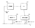
- FIG. 8 is a schematic diagram for explaining a method of a verification experiment of the transmission cycle calculation process according to the present embodiment.
- a PC Personal Computer
- the PC 101 is a general-purpose computer, and software for controlling the operation of the load generating device 103, software for acquiring the measurement result of the measuring device 104, and the like are installed.
- the verification board 102 is an FPGA (Field Programmable Gate Array) in which the functions of the ECU 2 according to the present embodiment are implemented.
- the verification board 102 is connected to the communication line 4 corresponding to the CAN bus, and transmits a message to be verified, that is, a message with a delay time at a predetermined cycle.
- the load generation device 103 is a device for transmitting a message that obstructs the verification target message transmitted by the verification board 102 to the communication line 4.
- the message that inhibits the verification target message is a message that corresponds to a message transmitted by another ECU 2 to the communication line 4 and delays the verification target message by arbitration processing.
- the load generation device 103 is connected to the PC 101, and the frequency of message transmission to the communication line 4 and the like are controlled by the PC 101. In this verification, PEAK System's "PCAN-USB" is used as the load generator 103.
- the measuring device 104 is a device that receives a message transmitted to the communication line 4 and gives information such as the content of the received message and the reception time to the PC 101.
- Vector's "VN1630A” is used as the measuring device 104, and the company's software "CANoe” is operated on the PC101 to obtain the verification result.
- the verification board 102 in this verification corresponds to the transmitting side ECU 2 in the in-vehicle communication system according to the present embodiment, and the measuring device 104 and the PC 101 correspond to the receiving side ECU 2.
- the calculation of the transmission cycle calculation of the ECU 2 according to the present embodiment was performed by the PC 101 based on the information given from the measuring device 104.
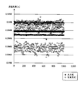
- FIG. 9 is a graph showing the results of a verification experiment of the transmission cycle calculation process according to the present embodiment.
- the periodic message transmission from the verification board 102 was performed 1000 times, and this message was received and the transmission cycle was calculated by the PC 101.
- the load generation device 103 transmits a load message so that the occupancy rate of the communication line 4 becomes 50%.
- the transmission cycle is calculated by the transmission cycle calculation method according to the above-described embodiment using the delay time given to the message and the conventional method of calculating the transmission cycle only by the time difference of the reception time without using the delay time. The method of 2 and 7 was performed. In the graph shown in FIG.
- the horizontal axis is the reception order of received messages
- the vertical axis is the transmission cycle [seconds] calculated based on the received messages, showing the results of the verification experiment.
- the calculation result of the transmission cycle by the transmission cycle calculation method according to the present embodiment is shown as a black circle
- the calculation result by the conventional method is shown as a white circle on the graph.
- the transmission cycle calculated by this method is aggregated to either 0.9987 or 0.9988, but the transmission cycle calculated by the conventional method is 0.9982 to 0. Widely varied between .9992.
- the reason why the result of this method is divided into two transmission cycles is due to the variation in the transmission timing of the message by the verification board 102 used in the verification experiment.
- the verification board 102 transmits a message at two timings when the transmission cycle is 0.9987 or 0.9988. Therefore, the message transmission cycle calculated by this method has little variation in the calculation result, and the transmission cycle of the transmission source is calculated with high accuracy.
- a delay time from the time when the transmitting ECU 2 first tries to transmit the message to the time when the message is actually transmitted is given to this message. ..
- the message transmitted from the transmitting side ECU 2 is received by the receiving side ECU 2 connected to the common communication line 4.
- the ECU 2 on the receiving side acquires the reception time of the received message and the delay time given to the received message.
- the ECU 2 on the receiving side acquires the reception time and the delay time for each of the two messages received before and after in chronological order, and calculates the message transmission cycle based on the acquired information.
- the ECU 2 on the receiving side can calculate the message transmission cycle in consideration of the transmission delay. Therefore, the ECU 2 on the receiving side can accurately calculate the message transmission cycle.
- the time retroactive by the delay time from the message reception time is the time when the message is first attempted to be transmitted, that is, the message transmission time. Therefore, the ECU 2 on the receiving side calculates the time difference between the time when the message received earlier is advanced by the delay time from the reception time and the time when the message received later is advanced by the delay time from the reception time, and this time difference is used as the message.
- the transmission cycle Since the receiving ECU 2 can calculate the message transmission cycle based on the time when the transmitting ECU 2 first tries to transmit the message, the message transmission cycle can be calculated accurately.
- the receiving ECU 2 periodically transmits the received message at a legitimate transmission cycle, or an unreasonable transmission cycle. Determines if it was transmitted aperiodically.
- the ECU 2 on the receiving side calculates, for example, the time difference in transmission time from the message received immediately before each time a message is received, and when the calculated time difference falls within a predetermined range with respect to the previously calculated transmission cycle, It can be determined that the received message is transmitted periodically.
- the ECU 2 on the receiving side may determine that the received message is transmitted aperiodically. it can.
- the message determined to be aperiodic may be, for example, a message transmitted by event driving, an illegal message by an illegal device, or the like.
- the ECU 2 is configured to send and receive messages according to the CAN communication standard, but the present invention is not limited to this, and for example, transmission and reception of messages according to the CAN-FD (CAN with Flexible Data rate) communication standard. May be done. Further, the ECU 2 may be configured to send and receive a message according to a communication standard different from CAN. Further, in the present embodiment, a part or all of the processing performed by the transmission processing unit 24a to the transmission cycle calculation unit 21a included in the CAN controller 24 may be performed by the processing unit 21 of the ECU 2. Further, a part or all of the processing shown in the flowchart of FIG. 7 may not be performed by the CAN controller 24, but may be performed by the processing unit 21. Further, the CAN controller 24 is configured to store the reception time and the delay time of the received message, but is not limited to this, and stores the transmission time of the message calculated based on the reception time and the delay time. It may be configured to be stored.
- CAN-FD CAN with Flexible Data rate
- FIG. 10 is a block diagram showing a configuration of an in-vehicle communication system according to the second embodiment.
- the in-vehicle communication system according to the second embodiment has both an ECU 2A having a function of adding a delay time to a message and an ECU 2C having a function of calculating a transmission cycle based on the delay time attached to the message. It is a system in which there is no ECU 2B.
- the ECU 2A assigns a delay time to the message transmitted by itself by the above method. However, the ECU 2A does not perform the process of calculating the transmission cycle for receiving the message, but only receives the message according to the normal CAN communication standard.
- the ECU 2B does not perform the above-mentioned processing such as assigning the delay time and calculating the transmission cycle, and transmits / receives a message according to a normal CAN communication standard.
- the ECU 2B may treat a message transmitted by the ECU 2A with a delay time as a message according to a normal CAN communication standard.
- the ECU 2C performs a process of calculating the transmission cycle using the delay time given to the message by the above method. However, the ECU 2C does not perform the process of giving a delay time to the message transmitted by itself.
- a message with a delay time and a message without a delay time are mixed. Therefore, each time the ECU 2C receives a message, it is necessary to determine whether the message is provided with a delay time or the message is not provided with a delay time.
- the ECU 2C according to the second embodiment stores in advance a table in which the CANID attached to the message and the information indicating whether or not the delay time is added to the message are associated with each other.
- the ECU 2C acquires the CANID of the received message and refers to the table to determine whether or not the received message has a delay time.
- the ECU 2C performs a process of calculating the transmission cycle for the message to which the delay time is given.
- the plurality of ECUs 2 connected to the common communication line 4 are not given a delay time to the ECU 2A that gives a delay time to the message and transmits the message.
- a CANID for identifying this message is attached to the messages sent and received by the ECUs 2A to 2C.
- the ECU 2C determines whether or not the delay time is added to the message based on the CANID of the received message. As a result, even when a message with a delay time and a message without a delay time are mixed, the ECU 2C on the receiving side can calculate the message transmission cycle.
- the in-vehicle communication system has a configuration in which three types of ECUs 2A to 2C are mixed, but ECUs having other configurations may be further mixed.
- ECUs having other configurations may be further mixed.
- an ECU having a function of assigning a delay time and transmitting a message and a function of calculating a transmission cycle using the delay time attached to the message may be further mixed.
- a plurality of ECUs similar to the ECUs 2A and 2C may be included in the in-vehicle communication system.
- the ECU 2C is configured to determine whether or not the received message has a delay time by referring to a table stored in advance, but the present invention is not limited to this. For example, information such as a flag indicating the presence or absence of a delay time may be included in the message.
- Each device in the in-vehicle communication system includes a computer including a microprocessor, ROM, RAM, and the like.
- An arithmetic processing unit such as a microprocessor reads a computer program including a part or all of each step of a sequence diagram or a flowchart as shown in FIGS. 4 and 7 from a storage unit such as a ROM or a RAM and executes the program. You can.
- the computer programs of these plurality of devices can be installed from an external server device or the like. Further, the computer programs of these plurality of devices are distributed in a state of being stored in a recording medium such as a CD-ROM, a DVD-ROM, or a semiconductor memory, respectively.
- Vehicle 2,2A, 2B, 2C ECU vehicle-mounted communication device
- CAN controller peripheral message determination unit, grant determination unit
- 24c Delay time granting unit (giving unit)
- 24d Reception processing unit 24e Reception time acquisition unit (Reception time acquisition unit) 24f Delay time acquisition unit
Landscapes
- Engineering & Computer Science (AREA)
- Computer Networks & Wireless Communication (AREA)
- Signal Processing (AREA)
- Environmental & Geological Engineering (AREA)
- Health & Medical Sciences (AREA)
- Computing Systems (AREA)
- General Health & Medical Sciences (AREA)
- Medical Informatics (AREA)
- Small-Scale Networks (AREA)
- Computer Security & Cryptography (AREA)
Abstract
メッセージの送信周期を精度よく算出することができる車載通信システム、車載通信装置及び送信周期算出方法を提供する。 メッセージの送信側の車載通信装置は、送信すべきメッセージの送信を最初に試みた時点から、当該メッセージの送信を開始した時点までの遅延時間を測定する遅延時間測定部と、遅延時間測定部が測定した遅延時間を前記メッセージに付与する付与部とを有し、メッセージの受信側の車載通信装置は、送信側の車載通信装置からのメッセージを受信した時点を取得する受信時点取得部と、受信したメッセージに付与された遅延時間を取得する遅延時間取得部と、受信した2つのメッセージそれぞれについて受信時点取得部が取得した時点及び遅延時間取得部が取得した遅延時間に基づき、メッセージの送信周期を算出する算出部とを有する。
Description
本開示は、共通の通信線を介してメッセージの送受信を行う車載通信システム及び車載通信装置に関し、また周期的に送信されるメッセージの送信周期を算出する送信周期算出方法に関する。
従来、車両にはECU(Electronic Control Unit)等の装置が複数搭載されている。これら複数の車載装置は通信線を介して相互に接続され、メッセージの送受信を行うことにより情報を交換し、協働により車両の種々の機能を実現している。車両内の通信には、CAN(Controller Area Network)の通信規格が広く採用されている。
特許文献1においては、車両内に配されるCANの通信線を多系統に分割した場合に、通信線間の通信を効率よく調停することが期待できる車載ネットワーク拡張装置が提案されている。この車載ネットワーク拡張装置は、通信線間で通信の衝突が生じた際に、メッセージに付与された優先度に基づいて通信線間の通信を調停する回路を備えている。
車両に搭載されたECU等の装置は、所定の情報を有するメッセージを周期的に送信することが多い。これを利用し、メッセージを受信する側の装置において、受信したメッセージについて送信周期を算出し、算出した送信周期が正しいものであるか否かを判定することによって、受信したメッセージの正否を判定することが可能である。しかしながら、複数の車載装置によるメッセージ送信が同時的に行われてメッセージの衝突が発生し、調停処理により優先度が低いメッセージの送信が遅延することが起こり得る。調停処理によるメッセージ送信の遅延が発生した場合、このメッセージを受信した装置では送信周期を算出することが難しく、送信周期に基づくメッセージの正否判定の精度を低下させる虞がある。
本開示は、斯かる事情に鑑みてなされたものであって、その目的とするところは、メッセージの送信周期を精度よく算出することができる車載通信システム、車載通信装置及び送信周期算出方法を提供することにある。
本態様に係る車載通信システムは、共通の通信線に接続された複数の車載通信装置が、前記通信線を介してメッセージを送受信する車載通信システムであって、メッセージの送信側の車載通信装置は、送信すべきメッセージの送信を最初に試みた時点から、当該メッセージの送信を開始した時点までの遅延時間を測定する遅延時間測定部と、前記遅延時間測定部が測定した遅延時間を前記メッセージに付与する付与部とを有し、メッセージの受信側の車載通信装置は、前記送信側の車載通信装置からのメッセージを受信した時点を取得する受信時点取得部と、受信したメッセージに付与された遅延時間を取得する遅延時間取得部と、受信した2つのメッセージそれぞれについて前記受信時点取得部が取得した時点及び前記遅延時間取得部が取得した遅延時間に基づき、前記メッセージの送信周期を算出する算出部とを有する。
本願は、このような特徴的な処理部を備える車載通信装置等の装置として実現することができるだけでなく、かかる特徴的な処理をステップとする通信方法として実現したり、かかるステップをコンピュータに実行させるためのコンピュータプログラムとして実現したりすることができる。これらの装置の一部又は全部を実現する半導体集積回路として実現したり、これらの装置を含むその他の装置又はシステムとして実現したりすることができる。
上記によれば、メッセージの送信周期を精度よく算出することが期待できる。
[本開示の実施の形態の説明]
最初に本開示の実施態様を列記して説明する。以下に記載する実施形態の少なくとも一部を任意に組み合わせてもよい。
最初に本開示の実施態様を列記して説明する。以下に記載する実施形態の少なくとも一部を任意に組み合わせてもよい。
(1)本態様に係る車載通信システムは、共通の通信線に接続された複数の車載通信装置が、前記通信線を介してメッセージを送受信する車載通信システムであって、メッセージの送信側の車載通信装置は、送信すべきメッセージの送信を最初に試みた時点から、当該メッセージの送信を開始した時点までの遅延時間を測定する遅延時間測定部と、前記遅延時間測定部が測定した遅延時間を前記メッセージに付与する付与部とを有し、メッセージの受信側の車載通信装置は、前記送信側の車載通信装置からのメッセージを受信した時点を取得する受信時点取得部と、受信したメッセージに付与された遅延時間を取得する遅延時間取得部と、受信した2つのメッセージそれぞれについて前記受信時点取得部が取得した時点及び前記遅延時間取得部が取得した遅延時間に基づき、前記メッセージの送信周期を算出する算出部とを有する。
本態様にあっては、送信側の車載通信装置が、メッセージの送信を最初に試みた時点から、このメッセージの送信を実際に開始した時点までの遅延時間を、このメッセージに付与する。送信側の車載通信装置から送信されたメッセージは、共通の通信線に接続された受信側の車載通信装置にて受信される。受信側の車載通信装置は、受信したメッセージの受信時点を取得すると共に、受信したメッセージに付与された遅延時間を取得する。受信側の車載通信装置は、時系列的に前後して受信した2つのメッセージについてそれぞれ受信時点及び遅延時間を取得し、取得したこれらの情報に基づいてメッセージの送信周期を算出する。送信側の車載通信装置が遅延時間をメッセージに付与して送信し、受信側の車載通信装置がメッセージから遅延時間を取得して送信周期を算出することにより、送信側の車載通信装置にて調停処理等により生じたメッセージ送信の遅延を受信側の車載通信装置が考慮してメッセージの送信周期を算出することができる。よって受信側の車載通信装置は、メッセージの送信周期を精度よく算出することができる。
(2)前記算出部は、先に受信したメッセージについて受信時点から遅延時間だけ遡った時点と、後に受信したメッセージについて受信時点から遅延時間だけ遡った時点との時間差を前記送信周期として算出することが好ましい。
本態様にあっては、メッセージの受信時点から遅延時間だけ遡った時点が、このメッセージの送信を最初に試みた時点となる。そこで受信側の車載通信装置は、先に受信したメッセージについて受信時点から遅延時間だけ遡った時点と、後に受信したメッセージについて受信時点から遅延時間だけ遡った時点との時間差を算出し、この時間差をメッセージの送信周期とする。送信側の車載通信装置がメッセージの送信を最初に試みた時点に基づいて、受信側の車載通信装置がメッセージの送信周期を算出することができるため、メッセージの送信周期を精度よく算出することができる。
(3)前記受信側の車載通信装置は、前記算出部が算出した送信周期に基づいて、受信したメッセージが周期的に送信されるメッセージ又は非周期的に送信されるメッセージのいずれであるかを判定する周期メッセージ判定部を有することが好ましい。
本態様にあっては、算出したメッセージの送信周期に基づいて、受信側の車載通信装置は、受信したメッセージが周期的に送信されるものであるか又は非周期的に送信されるものであるかを判定する。受信側の車載通信装置は、例えばメッセージを受信する都度、1つ前に受信したメッセージとの送信時点の時間差を算出し、算出した時間差が以前に算出した送信周期に対して誤差範囲内に収まる場合、受信メッセージが周期的に送信されるものであると判定することができる。これに対して、算出した時間差が送信周期に対して誤差範囲を超えて異なる値である場合、受信側の車載通信装置は、受信したメッセージが非周期的に送信されるものであると判定することができる。非周期的と判定されたメッセージは、例えばイベント駆動により送信されるメッセージ、又は、不正な装置による不正なメッセージ等の可能性がある。
(4)前記複数の車載通信装置には、前記遅延時間測定部及び前記付与部を有する車載通信装置と、前記遅延時間測定部及び前記付与部を有さない車載通信装置とを含むことが好ましい。
本態様にあっては、共通の通信線に接続される複数の車載通信装置には、メッセージに遅延時間を付与して送信する車載通信装置と、遅延時間の付与を行わずにメッセージを送信する車載通信装置とが含まれ得る。即ち、車載通信システムは、遅延時間が付与されたメッセージと、遅延時間が付与されていないメッセージとの混在が可能である。遅延時間を付与しない従来構成の車載通信システムに対して、メッセージの送信周期を精度よく判定することが求められる車載通信装置に対して遅延時間を付与する機能を追加すればよい。よって、本態様の車載通信システムの構成を従来の車両へ導入することを容易化できる。
(5)前記メッセージには、当該メッセージを識別する識別情報が付与され、前記受信側の車載通信装置は、受信したメッセージに付与された識別情報に基づいて、当該メッセージに遅延時間が付与されているか否かを判定する付与判定部を有することが好ましい。
本態様にあっては、車載通信装置が送受信するメッセージには、このメッセージを識別する識別情報が付与される。メッセージの識別情報は、例えばCANの通信規格ではCAN-IDとすることができる。ただし本態様の通信は、CANの通信規格に限定されるものではなく、例えばFlexRay又はイーサネット(登録商標)等の種々の通信規格が採用できる。受信側の車載通信装置は、受信したメッセージの識別情報に基づいて、このメッセージに遅延時間が付与されているか否かを判定する。これにより、遅延時間が付与されたメッセージと、遅延時間が付与されていないメッセージとが混在する場合であっても、受信側の車載通信装置がメッセージの送信周期の算出を行うことが可能となる。
(6)本態様に係る車載通信装置は、他の車載通信装置と共に共通の通信線に接続され、前記通信線を介してメッセージを送受信する車載通信装置であって、送信すべきメッセージの送信を最初に試みた時点から、当該メッセージの送信を開始した時点までの遅延時間が付与されたメッセージを受信する受信部と、前記受信部がメッセージを受信した時点を取得する受信時点取得部と、受信したメッセージに付与された遅延時間を取得する遅延時間取得部と、受信した2つのメッセージそれぞれについて前記受信時点取得部が取得した時点及び前記遅延時間取得部が取得した遅延時間に基づき、前記メッセージの送信周期を算出する算出部とを備える。
本態様にあっては、態様(1)と同様に、メッセージの送信周期を精度よく算出することができる。
(7)本態様に係る送信周期算出方法は、共通の通信線に接続された複数の車載通信装置が、前記通信線を介して送受信するメッセージの送信周期を算出する送信周期算出方法であって、メッセージの送信側の車載通信装置が、送信すべきメッセージの送信を最初に試みた時点から、当該メッセージの送信を開始した時点までの遅延時間を測定し、測定した遅延時間を前記メッセージに付与し、メッセージの受信側の車載通信装置が、前記送信側の車載通信装置からのメッセージを受信した時点を取得し、受信したメッセージに付与された遅延時間を取得し、受信した2つのメッセージそれぞれについて取得した時点及び遅延時間に基づき、前記メッセージの送信周期を算出する。
本態様にあっては、態様(1)と同様に、メッセージの送信周期を精度よく算出することができる。
[本開示の実施形態の詳細]
本開示の実施形態に係る車載通信システムの具体例を、以下に図面を参照しつつ説明する。本開示はこれらの例示に限定されるものではなく、請求の範囲によって示され、請求の範囲と均等の意味及び範囲内でのすべての変更が含まれることが意図される。
本開示の実施形態に係る車載通信システムの具体例を、以下に図面を参照しつつ説明する。本開示はこれらの例示に限定されるものではなく、請求の範囲によって示され、請求の範囲と均等の意味及び範囲内でのすべての変更が含まれることが意図される。
<システム構成>
図1は、本実施の形態に係る車載通信システムの構成を示すブロック図である。本実施の形態に係る車載通信システムは、車両1に搭載された複数のECU2を備えて構成されている。複数のECU2は、車両1内に配された通信線4にそれぞれ接続されており、通信線4を介してメッセージの送受信を行うことができる。なお本実施の形態において、複数のECU2は、CANの通信規格に従うメッセージの送受信を行う。通信線4はCANバスと呼ばれ、1つの通信線4には数個から十数個程度のECU2が接続され得る。車両1には複数の通信線4が設けられてもよく、この場合には通信線4の間のメッセージを中継するゲートウェイ等の装置が車両に搭載される。なお車載通信システムに含まれるECU2の数、通信線4の数、装置の接続態様及びネットワークの構成等は、図示のものに限らない。
図1は、本実施の形態に係る車載通信システムの構成を示すブロック図である。本実施の形態に係る車載通信システムは、車両1に搭載された複数のECU2を備えて構成されている。複数のECU2は、車両1内に配された通信線4にそれぞれ接続されており、通信線4を介してメッセージの送受信を行うことができる。なお本実施の形態において、複数のECU2は、CANの通信規格に従うメッセージの送受信を行う。通信線4はCANバスと呼ばれ、1つの通信線4には数個から十数個程度のECU2が接続され得る。車両1には複数の通信線4が設けられてもよく、この場合には通信線4の間のメッセージを中継するゲートウェイ等の装置が車両に搭載される。なお車載通信システムに含まれるECU2の数、通信線4の数、装置の接続態様及びネットワークの構成等は、図示のものに限らない。
ECU2は、例えば車両1のエンジンの動作を制御するECU、ドアのロック/アンロックを制御するECU、ライトの点灯/消灯を制御するECU、エアバッグの動作を制御するECU、及び、ABS(Antilock Brake System)の動作を制御するECU等の種々のECUが含まれ得る。なお、本実施の形態においては、通信線4を介したメッセージの送受信を行う車載通信装置としてECU2を挙げるが、車載通信装置はこれらに限るものではない。
CANの通信規格に従うメッセージには、CANIDと呼ばれる識別情報が、アービトレーションフィールドと呼ばれるメッセージの先頭領域に格納される。CANIDは、このメッセージに含まれるデータの種別等を示すと共に、このメッセージの優先度を示す情報である。CANIDは、その値が小さいほど優先度が高いメッセージであることを示す。複数のECU2が通信線4に対して同時的にメッセージの送信を試みた場合、CANの通信規格ではメッセージのアービトレーションフィールドに格納されたCANIDの値に基づくアービトレーション(調停)処理が各ECU2にて行われる。アービトレーション処理の結果、最も優先度が高い1つのメッセージが送信を許可され、これ以外のメッセージは送信を待機する必要がある。CANIDは、車両1、車載通信システム又はECU2の設計段階等において設計者により決定される値である。
本実施の形態に係る車載通信システムにおいては、ECU2がアービトレーション処理により生じた遅延時間の情報をメッセージに付与して送信する。このメッセージを受信したECU2は、メッセージの受信時刻(受信時点)と、このメッセージに付与された遅延時間とに基づいて、送信元のECU2がこのメッセージの送信を始めに試みた時刻(時点)、即ちアービトレーション処理による遅延が発生しなければ送信元のECU2がこのメッセージを送信できた送信時刻(送信時点)を算出することができる。
また本実施の形態において各ECU2は、所定の周期でメッセージ送信を繰り返し行う。送信周期は、例えばECU2毎に又はメッセージの種別毎(即ちCANID毎)に予め定められている。メッセージを受信したECU2は、受信したメッセージの受信時刻及び遅延時間と、この受信メッセージと同じCANIDを有する前回の受信メッセージの受信時刻及び遅延時間とに基づいて、前回のメッセージ送信時刻から今回のメッセージ送信時刻までの時間差を算出する。この時間差の算出は、このメッセージの送信周期を算出する処理に相当する。
本実施の形態に係るECU2は、メッセージを受信する都度、このメッセージの送信周期を算出する。ECU2は、今回の送信周期の算出結果と、前回までの送信周期の算出結果とを比較し、今回の送信周期が前回までの送信周期と大きく相違している場合に、今回の受信メッセージが想定される周期メッセージではないと判断する。本実施の形態においては、ECU2が周期メッセージではないと判断したメッセージは、不正なメッセージと見なされ、破棄される。ただし、非周期のメッセージは、例えばイベントメッセージ等の正規のメッセージとして処理されてもよい。
図2は、本実施の形態に係るECU2の構成を示すブロック図である。本実施の形態に係るECU2は、処理部(プロセッサ)21、記憶部(ストレージ)22、入出力部(I/O)23及びCANコントローラ24等を備えて構成されている。処理部21は、記憶部22に記憶されたプログラム22aを読み出して実行することにより、車両1の制御処理等の種々の処理を行う。処理部21は、制御処理等において他のECU2へのメッセージ送信が必要となった場合に、送信すべきメッセージをCANコントローラ24へ与えて、このメッセージの送信を指示する。また本実施の形態において処理部21は、受信したメッセージの送信周期を算出する処理を行う。
記憶部22は、例えばフラッシュメモリ又はEEPROM(Electrically Erasable Programmable Read Only Memory)等の不揮発性のメモリ素子を用いて構成されている。記憶部22は、処理部21が実行する各種のプログラム、及び、処理部21の処理に必要な各種のデータを記憶する。本実施の形態において記憶部22は、処理部21が実行するプログラム22aを記憶している。
プログラム22aは、例えばECU2の製造段階において記憶部22に書き込まれてもよい。例えばプログラム22aは、遠隔のサーバ装置などが配信するものをECU2が通信にて取得してもよい。例えばプログラム22aは、メモリカード又は光ディスク等の記録媒体に記録されたプログラム22aをECU2が読み出して記憶部22に記憶してもよい。例えばプログラム22aは、記録媒体に記録されたものを書込装置が読み出してECU2の記憶部22に書き込んでもよい。プログラム22aは、ネットワークを介した配信の態様で提供されてもよく、記録媒体に記録された態様で提供されてもよい。
入出力部23は、例えばセンサ5a及びアクチュエータ5b等の装置が信号線等を介して接続される。入出力部23は、センサ5a等の入力装置から入力される信号をサンプリングして取得し、取得した情報を処理部21へ与える。また入出力部23は、アクチュエータ5b等の制御対象装置に対する制御命令を処理部21から与えられた場合に、この制御命令に応じた制御信号を出力する。なおECU2は、入出力の両方を行う必要はなく、入力のみ又は出力のみを行う構成であってよく、更には入出力のいずれも行わない構成であってもよい。
CANコントローラ24は、通信線4を介したメッセージの送受信に関する処理を行う。CANコントローラ24は、例えば1つのIC(Integrated Circuit)として構成され得る。CANコントローラ24は、車両1内に配された通信線4に接続され、この通信線4を介して他のECU2との間でCANの通信規格に従うメッセージの送受信を行う。CANコントローラ24は、処理部21から与えられた送信用のメッセージをCANの通信規格に応じた電気信号に変換して通信線4へ出力することにより、他のECU2へのメッセージ送信を行う。CANコントローラ24は、通信線4の電位をサンプリングして取得することにより他のECU2からのメッセージを受信し、受信したメッセージを処理部21へ与える。
また本実施の形態に係るCANコントローラ24は、送信処理部24a、遅延時間測定部24b、遅延時間付与部24c、受信処理部24d、受信時刻取得部24e及び遅延時間取得部24f等を備えている。送信処理部24aは、処理部21から送信すべきメッセージ及び送信指示が与えられた場合に、このメッセージを通信線4へ出力することで他のECU2へ送信する処理を行う。また送信処理部24aは、他のECU2のメッセージ送信が同時的に行われた場合にアービトレーション処理を行う。送信処理部24aは、アービトレーション処理により送信権利を獲得した場合に、メッセージ送信を行う。
遅延時間測定部24bは、アービトレーション処理により送信権利を獲得できずにメッセージ送信が遅延した時間を測定する処理を行う。遅延時間測定部24bは、カウンタを用いて遅延時間を測定する。遅延時間測定部24bは、例えば処理部21から送信すべきメッセージ及び送信指示が与えられた際にカウンタの計時を開始する。その後、遅延時間測定部24bは、アービトレーション処理により送信権利を獲得した時点のカウンタの値を取得し、この値を遅延時間とする。例えばカウンタの値が100であり、カウンタを動作させるクロックの周期が1μ秒である場合、実際の遅延時間は100μ秒となる。本実施の形態においては、カウンタのクロック周期の値が複数のECU2にとって既知のものであるとし、このカウンタの値を遅延時間として扱う。
遅延時間付与部24cは、遅延時間測定部24bが測定した遅延時間(に相当するカウンタの値)を、送信メッセージに付与する処理を行う。遅延時間付与部24cは、例えばCANの通信規格に従うメッセージのデータフィールドの一部に遅延時間を格納する。
受信処理部24dは、他のECU2から送信されたメッセージを受信する処理を行う。受信処理部24dは、通信線4の電位を繰り返しサンプリングすることでメッセージを受信し、受信したメッセージを処理部21へ与える。
受信時刻取得部24eは、他のECU2からのメッセージを受信処理部24dにて受信した時刻を取得する処理を行う。本実施の形態においてCANコントローラ24は、現在の時刻を計時するタイマ機能を備えている。CANコントローラ24にて計時される時刻は、他の装置と共有される絶対的な時刻であってもよく、自装置のみで用いられる相対的な時刻であってもよい。例えば、タイマ機能はカウンタにより実現され、CANコントローラ24の起動と共にカウンタを動作させることで、起動からの相対的な時間をカウンタで計測することができる。受信時刻取得部24eは、メッセージを受信したタイミングでタイマ機能のカウンタの値を取得することで、メッセージの受信時刻を取得する。
遅延時間取得部24fは、受信したメッセージに付与された遅延時間の情報を取得する処理を行う。本実施の形態においてはメッセージのデータフィールドの一部に遅延時間の情報が格納されている。遅延時間取得部24fは、受信したメッセージのデータフィールドの所定箇所から遅延時間の情報を抽出して取得する。
CANコントローラ24は、受信処理部24dが受信したメッセージの内容、受信時刻取得部24eが取得した受信時刻、及び、遅延時間取得部24fが取得した遅延時間等の情報を、処理部21へ与える。
本実施の形態において処理部21には、送信周期算出部21aが設けられる。送信周期算出部21aは、記憶部22に記憶されたプログラム22aを処理部21が実行することにより実現されるソフトウェア的な機能ブロックである。ただし、送信周期算出部21aをハードウェア的な機能ブロックとして実現してもよい。
上述のように、CANコントローラ24はメッセージを受信する都度、このメッセージの内容、受信時刻及び遅延時間等の情報を処理部21へ与える。CANコントローラ24から与えられたこれらの情報に基づいて、処理部21の送信周期算出部21aは、受信したメッセージと前回に受信したメッセージとの時間差を算出することにより、このメッセージの送信周期を算出する処理を行う。このため送信周期算出部21aは、前回に受信したメッセージについての受信時刻及び遅延時間の情報(又は、受信時刻及び遅延時間から算出されるメッセージの送信時刻の情報であってもよい)を記憶している。送信周期算出部21aは、前回の受信メッセージの受信時刻及び遅延時間と、今回の受信メッセージの受信時刻及び遅延時間とを基に、このメッセージの送信周期を算出する。
例えば、あるECUαが周期的にメッセージMαを送信し、このメッセージの送信周期がTαであるものとする。即ち、ECUαでは処理部21からCANコントローラ24へ周期Tαで送信メッセージ及び送信指示が与えられている。ECUαが送信するメッセージMαをECUβが受信する場合に、連続してECUβが受信するメッセージMα0、Mα1、…、Mαnの受信時刻の列をtβ={tβ0、tβ1、…、tβn}とする。このときに各受信時刻に対応する遅延時間の列をd={d0、d1、…、dn}とする。
この場合に、ECUβが受信時刻tβ0にて受信したメッセージMα0について、ECUαにおいて送信指示がなされた時刻(メッセージの生成時刻)tα0は、以下の(1)式を用いて算出することができる。
tα0 = tβ0-d0 …(1)
tα0 = tβ0-d0 …(1)
よって、連続する2つのメッセージMα0、Mα1の送信間隔Tβは、以下の(2)式を用いて算出することができる。
Tβ = (tβ1-d1)-(tβ0-d0) …(2)
Tβ = (tβ1-d1)-(tβ0-d0) …(2)
この(2)式にて算出される送信間隔Tβは、ECUαによるメッセージMの送信周期Tαに相当する。ただしECUα及びECUβのクロック信号の誤差等が存在するため、Tα及びTβにはこれらの誤差による差異が存在する可能性がある。即ち、Tβ≒Tαである。また送信周期算出部21aはCANコントローラ24が備えてもよく、この場合には送信周期の算出結果をCANコントローラ24が処理部21へ与える。
処理部21は、送信周期算出部21aが算出した送信周期に基づいて受信メッセージの正否判定等を行うことができる。なお本実施の形態においては、受信メッセージの送信周期の算出を処理部21が行うが、送信周期の算出はCANコントローラ24が行い、算出結果をCANコントローラ24が処理部21へ与えてもよい。この場合、算出した送信周期に基づく受信メッセージの正否判定等をCANコントローラ24が行ってもよい。
<送信周期算出方法>
図3は、本実施の形態に係る車載通信システムにおいてECU2が送信するメッセージの構成を説明するための模式図である。CANの通信規格に従うメッセージには、アービトレーションフィールド、コントロールフィールド、データフィールド、CRC(Cyclic Redundancy Check)フィールド及びACKフィールド等が含まれる。本実施の形態に係るメッセージでは、アービトレーションフィールドにCANIDが格納され、データフィールドの一部に遅延時間の情報が格納される。
図3は、本実施の形態に係る車載通信システムにおいてECU2が送信するメッセージの構成を説明するための模式図である。CANの通信規格に従うメッセージには、アービトレーションフィールド、コントロールフィールド、データフィールド、CRC(Cyclic Redundancy Check)フィールド及びACKフィールド等が含まれる。本実施の形態に係るメッセージでは、アービトレーションフィールドにCANIDが格納され、データフィールドの一部に遅延時間の情報が格納される。
CANの通信規格では、メッセージのデータフィールドのサイズは最大8バイトである。このうち遅延時間を格納するための領域のサイズは、例えば2バイト~4バイトとすることができる。遅延時間のサイズは、車載通信システムの設計段階等において、例えば最大の遅延時間に基づき、予め決定される。遅延時間を計測するためのカウンタを動作させるクロック信号の周期を例えば2μ秒とすると、2バイトの遅延時間は最大で約130m秒であり、3バイトの遅延時間は最大で約33秒であり、4バイトの遅延時間は最大で約67秒である。
CANコントローラ24は、処理部21から与えられたメッセージをMSB(Most Significant Bit)側、即ちアービトレーションフィールド側から順に通信線4へ出力することにより、メッセージの送信を開始する。メッセージの送信開始と共に、CANコントローラ24は、カウンタによる遅延時間の測定を開始する。メッセージの送信開始からアービトレーションフィールドの送信完了までの間にアービトレーション処理が行われ、アービトレーションフィールドの最終ビットの送信を完了した時点でアービトレーション処理の結果、即ちメッセージの送信権利の有無が確定する。アービトレーション処理により送信権利の獲得が確定した場合、CANコントローラ24は、カウンタにより測定される遅延時間を取得し、取得した遅延時間をデータフィールドの所定箇所に格納する。その後、CANコントローラ24は、コントロールフィールド、データフィールド、CRCフィールド及びACKフィールドを順に送信し、メッセージ送信を完了する。
図4は、本実施の形態に係るCANコントローラ24が行うメッセージ送信処理の手順を示すフローチャートである。本実施の形態に係るCANコントローラ24の送信処理部24aは、処理部21から送信すべきメッセージと共に送信指示が与えられたか否かを判定する(ステップS1)。送信指示が与えられていない場合(S1:NO)、送信処理部24aは、送信指示が与えられるまで待機する。送信指示が与えられた場合(S1:YES)、CANコントローラ24の遅延時間測定部24bは、カウンタによる遅延時間のカウントを開始する(ステップS2)。
送信処理部は、送信メッセージの先頭部分から送信を開始し、まずアービトレーションフィールドの送信処理を行う(ステップS3)。このときに送信処理部24aは、他のECU2との間でアービトレーション処理を行い、アービトレーションフィールドの最終ビットの送信により送信権利の有無が確定する。送信処理部24aは、アービトレーション処理の結果に基づいて、自身のメッセージの送信が可能であるか否かを判定する(ステップS4)。メッセージの送信が不可能である場合(S4:NO)、送信処理部24aは、他のECU2によるメッセージ送信が終了するまで待機し(ステップS5)、ステップS3へ処理を戻して再度のメッセージ送信を試みる。
メッセージの送信が可能である場合(S4:YES)、遅延時間測定部24bは、カウンタがカウントした遅延時間を取得する(ステップS6)。CANコントローラ24の遅延時間付与部24cは、ステップS6にて取得した遅延時間を、送信メッセージのデータフィールドの所定箇所に付与する(ステップS7)。送信処理部24aは、送信メッセージのコントロールフィールド以降についての送信処理を行い(ステップS8)、メッセージ送信処理を終了する。
図5及び図6は、本実施の形態に係る送信周期算出方法を説明するための模式図である。図5には、1つのメッセージについての時刻(時点)及び時間の関係を図示している。図5に示す例では、CANコントローラ24が処理部21から送信指示を与えられてメッセージの送信を最初に試みた時点を送信開始の時刻t0としている。本例では、このメッセージの送信は他のECU2のメッセージ送信により待機させられ、その後の時刻t1にてメッセージの再送信が試みられている。このメッセージはアービトレーションフィールドの最終ビットを送信した時刻t2にて送信権利が確定し、この時点での遅延時間Dがメッセージのデータフィールドの所定箇所に付与される。CANコントローラ24は、メッセージの残りの部分を送信し、時刻t3にてメッセージの送信を完了する。その後、メッセージの送信開始時刻t0からこのメッセージの送信周期Tが経過した時刻t4にて、CANコントローラ24は、次のメッセージの送信を試みる。
このメッセージを受信するECU2のCANコントローラ24は、アービトレーション処理によりこのメッセージの送信が確定した時刻t2を、このメッセージの受信時刻とする。CANコントローラ24は、その後の時刻t3にてメッセージの受信を完了し、受信メッセージのデータフィールドの所定箇所から遅延時間Dを取得する。CANコントローラ24は、メッセージの受信時刻及び遅延時間の情報を処理部21へ与える。処理部21は、メッセージの受信時刻t2から遅延時間Dを遡った時刻t0をこのメッセージの送信時刻t0として算出することができる。処理部21は、CANコントローラ24がメッセージを受信する都度、同様にしてメッセージの送信時刻を算出し、時系列的に連続する2つの受信メッセージについて送信時刻の時間差を算出することで、このメッセージの送信周期Tを算出することができる。
なお、送信側のECU2のCANコントローラ24がメッセージに付与する遅延時間Dは、送信するメッセージの長さを事前に計算し、このメッセージの送信完了の時刻t3までの時間、即ち(t3-t0)に相当する時間としてもよい。この場合、受信側のECU2は、メッセージの受信完了の時点をメッセージの受信時刻とする。
図6には、4つのメッセージM0~M3について、受信時刻及び遅延時間の例が示されている。なお本図における受信時刻及び遅延時間等は、メッセージを受信したECU2のCANコントローラ24が備えるタイマ機能のカウンタにより計時されたカウンタ値を用いて示されている。例えばメッセージM0は、受信時刻1100にて受信され、遅延時間として100が付されている。同様に、メッセージM1は、受信時刻2100にて受信され、遅延時間として100が付されている。メッセージM2は、受信時刻3210にて受信され、遅延時間として210が付されている。メッセージM3は、受信時刻4175にて受信され、遅延時間として175が付されている。
メッセージを受信したECU2は、メッセージの受信時刻から遅延時間だけ遡った時刻を送信時刻として算出することができる。本例では、メッセージM0の送信時刻は1000であり、メッセージM1の送信時刻は2000であり、メッセージM2の送信時刻は3000であり、メッセージM3の送信時刻は4000である。ECU2は、時系列的に連続する2つのメッセージの送信時刻の時間差を算出する。本例では、メッセージM0及びM1の送信時刻の時間差は1000であり、メッセージM1及びM2の送信時刻の時間差は1000であり、メッセージM2及びM3の送信時刻の時間差は1000である。よってECU2は、このメッセージの送信周期が1000であると判定することができる。
図7は、本実施の形態に係るECU2が行う送信周期算出処理の手順を示すフローチャートである。本実施の形態に係るECU2のCANコントローラ24の受信処理部24dは、通信線4に対する他のECU2のメッセージ送信の有無を判定する(ステップS21)。メッセージが送信されていない場合(S21:NO)、受信処理部24dは、他のECU2がメッセージを送信するまで待機する。
他のECU2によるメッセージが送信された場合(S21:YES)、CANコントローラ24の受信時刻取得部24eは、CANコントローラ24のタイマ機能に基づいて、このメッセージの受信時刻を取得する(ステップS22)。このときに受信時刻取得部24eは、このメッセージのアービトレーションフィールドまでの受信を完了した時点を、受信時刻として取得する。その後、CANコントローラ24の遅延時間取得部24fは、受信したメッセージのデータフィールドの所定箇所に付与された遅延時間を取得する(ステップS23)。CANコントローラ24が取得した受信時刻及び遅延時間の情報は、処理部21へ与えられる。処理部21の送信周期算出部21aは、前回に受信したメッセージについて記憶した受信時刻及び遅延時間の情報を読み出す(ステップS24)。送信周期算出部21aは、前回の受信メッセージの受信時刻及び遅延時間と、今回の受信メッセージの受信時刻及び遅延時間とに基づいて、このメッセージの送信周期を算出する(ステップS25)。
処理部21は、ステップS25にて算出した送信周期が正しい送信周期であるか否かを判定する(ステップS26)。例えば処理部21は、予めメッセージのCANIDに対して正当な送信周期が定められたテーブル等の情報を有しており、算出した送信周期がテーブル等に記憶された正当な送信周期と一致するか否か、又は、算出した送信周期と正当な送信周期との差が閾値内であるか否か等を判定することにより、算出した送信周期が正当なものであるか否かを判定することができる。また例えば処理部21は、以前に算出した送信周期と今回に算出した送信周期とを比較し、両送信周期の差が閾値内であるか否かを判定することにより、送信周期が正当なものであるか否かを判定することができる。送信周期の正否判定は、どのような方法で行われてもよい。
処理部21は、受信メッセージの送信周期が正しい送信周期であると判定した場合(S26:YES)、このメッセージの受信処理を行い(ステップS27)、受信したメッセージの内容に応じた種々の処理を行う。また処理部21は、今回に受信したメッセージについて受信時刻及び遅延時間の情報を記憶し(ステップS28)、処理を終了する。受信時刻及び遅延時間の記憶は、記憶部22又は処理部21の内部にあるレジスタ等の記憶領域を用いて行われる。
また処理部21は、受信メッセージの送信周期が正しい送信周期ではないと判定した場合(S26:NO)、このメッセージを破棄する処理を行い(ステップS29)、処理を終了する。メッセージの破棄は、例えば処理部21が受信メッセージを用いた処理を行わないことにより実現される。なお送信周期の算出及び判定等をCANコントローラ24が行う構成の場合には、送信周期が正しくないと判定したメッセージの受信が完了する前に、CANコントローラ24がエラーフレームを通信線4に対して出力することにより、このメッセージが他のECU2にて受信されることを阻止してもよい。
なお本フローチャートにおいては、送信周期が正しくないと判定したメッセージは不正なメッセージとして扱っているが、これに限るものではない。例えば送信周期が正しくないと判定したメッセージを、イベントメッセージ等の正当な非周期メッセージとして扱ってもよい。
<検証実験>
図8は、本実施の形態に係る送信周期算出処理の検証実験の方法を説明するための模式図である。本実施の形態に係る送信周期算出処理の検証実験には、PC(Personal Computer)101、検証用ボード102、負荷生成装置103及び計測装置104が用いられている。PC101は、汎用のコンピュータであり、負荷生成装置103の動作を制御するソフトウェア、及び、計測装置104の計測結果を取得するソフトウェア等がインストールされている。検証用ボード102は、本実施の形態に係るECU2の機能をFPGA(Field Programmable Gate Array)にて実装したものである。本検証では、ALTERA社のFPGAが搭載された「DE2-115」を検証用ボード102として利用している。検証用ボード102は、CANバスに相当する通信線4に接続され、検証対象のメッセージ、即ち遅延時間を付与したメッセージを所定周期で送信する。
図8は、本実施の形態に係る送信周期算出処理の検証実験の方法を説明するための模式図である。本実施の形態に係る送信周期算出処理の検証実験には、PC(Personal Computer)101、検証用ボード102、負荷生成装置103及び計測装置104が用いられている。PC101は、汎用のコンピュータであり、負荷生成装置103の動作を制御するソフトウェア、及び、計測装置104の計測結果を取得するソフトウェア等がインストールされている。検証用ボード102は、本実施の形態に係るECU2の機能をFPGA(Field Programmable Gate Array)にて実装したものである。本検証では、ALTERA社のFPGAが搭載された「DE2-115」を検証用ボード102として利用している。検証用ボード102は、CANバスに相当する通信線4に接続され、検証対象のメッセージ、即ち遅延時間を付与したメッセージを所定周期で送信する。
負荷生成装置103は、検証用ボード102が通信線4に対して送信する検証対象メッセージを阻害するメッセージを送信するための装置である。検証対象メッセージを阻害するメッセージとは、通信線4に対して他のECU2が送信するメッセージに相当し、アービトレーション処理により検証対象メッセージを遅延させるメッセージである。負荷生成装置103はPC101に接続され、通信線4に対するメッセージ送信の頻度等はPC101により制御される。本検証では、PEAK System社の「PCAN-USB」を負荷生成装置103として利用している。
計測装置104は、通信線4に対して送信されるメッセージを受信し、受信したメッセージの内容及び受信時刻等の情報をPC101へ与える装置である。本検証では、Vector社の「VN1630A」を計測装置104として用い、同社のソフトウェア「CANoe」をPC101にて動作させて検証結果を取得している。本検証における検証用ボード102が本実施の形態に係る車載通信システムにおける送信側のECU2に相当し、計測装置104及びPC101が受信側のECU2に相当する。本実施の形態に係るECU2の送信周期算出の演算は、計測装置104から与えられる情報に基づいてPC101にて行った。
図9は、本実施の形態に係る送信周期算出処理の検証実験の結果を示すグラフである。本検証では、検証用ボード102からの周期的なメッセージ送信を1000回行い、このメッセージを受信してPC101にて送信周期を算出した。なお負荷生成装置103は、通信線4の占有率が50%となるように負荷となるメッセージを送信している。送信周期の算出は、メッセージに付与された遅延時間を利用する上述の本実施の形態に係る送信周期算出方法と、遅延時間を利用せずに受信時刻の時間差のみで送信周期を算出する従来方法との2つ7の方法で行った。図9に示すグラフは、横軸を受信メッセージの受信順序とし、縦軸を受信メッセージに基づいて算出された送信周期[秒]として検証実験の結果を示したものである。本実施の形態に係る送信周期算出方法による送信周期の算出結果を黒丸とし、従来方式による算出結果を白丸としてグラフ上に示してある。
図示の検証実験の結果によれば、本方式では算出される送信周期が0.9987又は0.9988のいずれかに集約されているが、従来方式では算出される送信周期が0.9982から0.9992の間で広範囲にわたってばらついている。なお、本方式の結果が2つの送信周期に分かれているのは、検証実験に用いた検証用ボード102によるメッセージの送信タイミングのバラツキに起因するものである。検証用ボード102は、送信周期が0.9987又は0.9988となる2つのタイミングでメッセージを送信している。よって本方式により算出されるメッセージの送信周期は、算出結果のバラツキが少なく、送信元の送信周期が精度よく算出されたものとなっている。
<まとめ>
以上の構成の本実施の形態に係る車載通信システムは、送信側のECU2がメッセージの送信を最初に試みた時点から、このメッセージを実際に送信した時点までの遅延時間を、このメッセージに付与する。送信側のECU2から送信されたメッセージは、共通の通信線4に接続された受信側のECU2にて受信される。受信側のECU2は、受信したメッセージの受信時刻を取得すると共に、受信したメッセージに付与された遅延時間を取得する。受信側のECU2は、時系列的に前後して受信した2つのメッセージについてそれぞれ受信時刻及び遅延時間を取得し、取得したこれらの情報に基づいてメッセージの送信周期を算出する。送信側のECU2が遅延時間をメッセージに付与して送信し、受信側のECU2がメッセージから遅延時間を取得して送信周期を算出することにより、送信側のECU2にてアービトレーション処理等により生じたメッセージ送信の遅延を受信側のECU2が考慮してメッセージの送信周期を算出することができる。よって受信側のECU2は、メッセージの送信周期を精度よく算出することができる。
以上の構成の本実施の形態に係る車載通信システムは、送信側のECU2がメッセージの送信を最初に試みた時点から、このメッセージを実際に送信した時点までの遅延時間を、このメッセージに付与する。送信側のECU2から送信されたメッセージは、共通の通信線4に接続された受信側のECU2にて受信される。受信側のECU2は、受信したメッセージの受信時刻を取得すると共に、受信したメッセージに付与された遅延時間を取得する。受信側のECU2は、時系列的に前後して受信した2つのメッセージについてそれぞれ受信時刻及び遅延時間を取得し、取得したこれらの情報に基づいてメッセージの送信周期を算出する。送信側のECU2が遅延時間をメッセージに付与して送信し、受信側のECU2がメッセージから遅延時間を取得して送信周期を算出することにより、送信側のECU2にてアービトレーション処理等により生じたメッセージ送信の遅延を受信側のECU2が考慮してメッセージの送信周期を算出することができる。よって受信側のECU2は、メッセージの送信周期を精度よく算出することができる。
また本実施の形態においては、メッセージの受信時刻から遅延時間だけ遡った時刻が、このメッセージの送信を最初に試みた時刻、即ちメッセージの送信時刻となる。そこで受信側のECU2は、先に受信したメッセージについて受信時刻から遅延時間だけ遡った時刻と、後に受信したメッセージについて受信時刻から遅延時間だけ遡った時刻との時間差を算出し、この時間差をメッセージの送信周期とする。送信側のECU2がメッセージの送信を最初に試みた時刻に基づいて、受信側のECU2がメッセージの送信周期を算出することができるため、メッセージの送信周期を精度よく算出することができる。
また本実施の形態においては、算出したメッセージの送信周期に基づいて、受信側のECU2は、受信したメッセージが正当な送信周期で周期的に送信されたものであるか、又は、不当な送信周期で非周期的に送信されたものであるかを判定する。受信側のECU2は、例えばメッセージを受信する都度、1つ前に受信したメッセージとの送信時刻の時間差を算出し、算出した時間差が以前に算出した送信周期に対して所定範囲内に収まる場合、受信メッセージが周期的に送信されるものであると判定することができる。これに対して、算出した時間差が送信周期に対して所定範囲を超えて異なる値である場合、受信側のECU2は、受信したメッセージが非周期的に送信されるものであると判定することができる。非周期と判定されるメッセージは、例えばイベント駆動により送信されるメッセージ、又は、不正な装置による不正なメッセージ等の可能性がある。
なお本実施の形態においては、ECU2がCANの通信規格に従うメッセージの送受信を行う構成としたが、これに限るものではなく、例えばCAN-FD(CAN with Flexible Data rate)の通信規格に従うメッセージの送受信を行ってもよい。またECU2は、CANとは異なる通信規格に従うメッセージの送受信を行う構成であってもよい。また本実施の形態においてCANコントローラ24が備える送信処理部24a~送信周期算出部21aが行う処理の一部又は全部は、ECU2の処理部21にて行われてもよい。また図7のフローチャートに示した処理の一部又は全部は、CANコントローラ24が行うのではなく、処理部21が行ってもよい。またCANコントローラ24は、受信メッセージの受信時刻及び遅延時間を記憶しておく構成としたが、これに限るものではなく、受信時刻及び遅延時間を基に算出されたメッセージの送信時刻を記憶しておく構成であってもよい。
<実施の形態2>
図10は、実施の形態2に係る車載通信システムの構成を示すブロック図である。実施の形態2に係る車載通信システムは、メッセージに遅延時間を付す機能を有するECU2Aと、メッセージに付された遅延時間に基づく送信周期を算出する機能を有するECU2Cと、これらの両機能を有さないECU2Bとが混在するシステムである。
図10は、実施の形態2に係る車載通信システムの構成を示すブロック図である。実施の形態2に係る車載通信システムは、メッセージに遅延時間を付す機能を有するECU2Aと、メッセージに付された遅延時間に基づく送信周期を算出する機能を有するECU2Cと、これらの両機能を有さないECU2Bとが混在するシステムである。
ECU2Aは、上述の方法により、自身が送信するメッセージに対して遅延時間を付与する。ただしECU2Aは、メッセージの受信に関しては送信周期を算出する処理を行わず、通常のCANの通信規格に従うメッセージ受信を行うのみである。ECU2Bは、上述の遅延時間の付与及び送信周期の算出等の処理を行わず、通常のCANの通信規格に従ってメッセージの送受信を行う。ECU2Bは、ECU2Aが送信する遅延時間が付与されたメッセージについて、これを通常のCANの通信規格に従うメッセージとして扱えばよい。ECU2Cは、上述の方法により、メッセージに付与された遅延時間を用いて送信周期を算出する処理を行う。ただしECU2Cは、自身が送信するメッセージに対して遅延時間を付与する処理は行わない。
実施の形態2に係る車載通信システムでは、遅延時間が付与されたメッセージと、遅延時間が付与されていないメッセージとが混在することとなる。このためECU2Cは、メッセージを受信する都度、遅延時間が付与されたメッセージであるか又は遅延時間が付与されていないメッセージであるかを判定する必要がある。実施の形態2に係るECU2Cは、メッセージに付されるCANIDと、このメッセージに遅延時間が付与されるか否かを示す情報とが対応付けられたテーブルを予め記憶している。ECU2Cは、受信したメッセージのCANIDを取得してテーブルを参照することにより、この受信メッセージに遅延時間が付されているか否かを判定する。遅延時間が付与されたメッセージに対して、ECU2Cは、送信周期を算出する処理を行う。
以上の構成の実施の形態2に係る車載通信システムは、共通の通信線4に接続される複数のECU2には、メッセージに遅延時間を付与して送信するECU2Aと、遅延時間の付与を行わずにメッセージを送信するECU2B及び2Cとが含まれる。即ち、実施の形態2に係る車載通信システムでは、遅延時間が付与されたメッセージと、遅延時間が付与されていないメッセージとが混在する。遅延時間を付与しないメッセージを送受信する従来構成のCANの車載通信システムに対して、メッセージの送信周期を精度よく判定することが求められるECU2Aについてのみ遅延時間を付与する機能を追加すればよいため、遅延時間を用いた送信周期の判定を行う構成を、従来の車載通信システムに対して導入することを容易化できる。
また実施の形態2に係る車載通信システムでは、ECU2A~2Cが送受信するメッセージには、このメッセージを識別するためのCANIDが付されている。メッセージを受信したECU2Cは、受信したメッセージのCANIDに基づいて、このメッセージに遅延時間が付与されているか否かを判定する。これにより、遅延時間が付与されたメッセージと、遅延時間が付与されていないメッセージとが混在する場合であっても、受信側のECU2Cがメッセージの送信周期の算出を行うことが可能となる。
なお実施の形態2に係る車載通信システムは、3種のECU2A~2Cが混在する構成であるが、これ以外の構成のECUが更に混在してもよい。例えば、遅延時間を付与してメッセージを送信する機能と、メッセージに付された遅延時間を用いて送信周期を算出する機能とを備えるECUが更に混在してもよい。また、ECU2A、2Cと同様のECUは、車載通信システムに複数が含まれていてよい。またECU2Cは、予め記憶したテーブルを参照して受信メッセージに遅延時間が付されているか否かを判定する構成としたが、これに限るものではない。例えばメッセージ中に遅延時間の有無を示すフラグ等の情報を含めてもよい。
車載通信システムにおける各装置は、マイクロプロセッサ、ROM及びRAM等を含んで構成されるコンピュータを備える。マイクロプロセッサ等の演算処理部は、図4及び図7に示すような、シーケンス図又はフローチャートの各ステップの一部又は全部を含むコンピュータプログラムを、ROM、RAM等の記憶部からそれぞれ読み出して実行してよい。これら複数の装置のコンピュータプログラムは、それぞれ、外部のサーバ装置等からインストールすることができる。また、これら複数の装置のコンピュータプログラムは、それぞれ、CD-ROM、DVD-ROM、半導体メモリ等の記録媒体に格納された状態で流通する。
今回開示された実施形態はすべての点で例示であって、制限的なものではないと考えられるべきである。本開示の範囲は、上記した意味ではなく、請求の範囲によって示され、請求の範囲と均等の意味及び範囲内でのすべての変更が含まれることが意図される。
1 車両
2,2A,2B,2C ECU(車載通信装置)
4 通信線
5a センサ
5b アクチュエータ
21 処理部
21a 送信周期算出部(算出部)
22 記憶部
22a プログラム
23 入出力部
24 CANコントローラ(周期メッセージ判定部、付与判定部)
24a 送信処理部
24b 遅延時間測定部
24c 遅延時間付与部(付与部)
24d 受信処理部
24e 受信時刻取得部(受信時点取得部)
24f 遅延時間取得部
2,2A,2B,2C ECU(車載通信装置)
4 通信線
5a センサ
5b アクチュエータ
21 処理部
21a 送信周期算出部(算出部)
22 記憶部
22a プログラム
23 入出力部
24 CANコントローラ(周期メッセージ判定部、付与判定部)
24a 送信処理部
24b 遅延時間測定部
24c 遅延時間付与部(付与部)
24d 受信処理部
24e 受信時刻取得部(受信時点取得部)
24f 遅延時間取得部
Claims (7)
- 共通の通信線に接続された複数の車載通信装置が、前記通信線を介してメッセージを送受信する車載通信システムであって、
メッセージの送信側の車載通信装置は、
送信すべきメッセージの送信を最初に試みた時点から、当該メッセージの送信を開始した時点までの遅延時間を測定する遅延時間測定部と、
前記遅延時間測定部が測定した遅延時間を前記メッセージに付与する付与部と
を有し、
メッセージの受信側の車載通信装置は、
前記送信側の車載通信装置からのメッセージを受信した時点を取得する受信時点取得部と、
受信したメッセージに付与された遅延時間を取得する遅延時間取得部と、
受信した2つのメッセージそれぞれについて前記受信時点取得部が取得した時点及び前記遅延時間取得部が取得した遅延時間に基づき、前記メッセージの送信周期を算出する算出部と
を有する、
車載通信システム。 - 前記算出部は、先に受信したメッセージについて受信時点から遅延時間だけ遡った時点と、後に受信したメッセージについて受信時点から遅延時間だけ遡った時点との時間差を前記送信周期として算出する、請求項1に記載の車載通信システム。
- 前記受信側の車載通信装置は、前記算出部が算出した送信周期に基づいて、受信したメッセージが周期的に送信されるメッセージ又は非周期的に送信されるメッセージのいずれであるかを判定する周期メッセージ判定部を有する、請求項1又は請求項2に記載の車載通信システム。
- 前記複数の車載通信装置には、
前記遅延時間測定部及び前記付与部を有する車載通信装置と、
前記遅延時間測定部及び前記付与部を有さない車載通信装置と
を含む、請求項1から請求項3までのいずれか1項に記載の車載通信システム。 - 前記メッセージには、当該メッセージを識別する識別情報が付与され、
前記受信側の車載通信装置は、
受信したメッセージに付与された識別情報に基づいて、当該メッセージに遅延時間が付与されているか否かを判定する付与判定部を有する、請求項4に記載の車載通信システム。 - 他の車載通信装置と共に共通の通信線に接続され、前記通信線を介してメッセージを送受信する車載通信装置であって、
送信すべきメッセージの送信を最初に試みた時点から、当該メッセージの送信を開始した時点までの遅延時間が付与されたメッセージを受信する受信部と、
前記受信部がメッセージを受信した時点を取得する受信時点取得部と、
受信したメッセージに付与された遅延時間を取得する遅延時間取得部と、
受信した2つのメッセージそれぞれについて前記受信時点取得部が取得した時点及び前記遅延時間取得部が取得した遅延時間に基づき、前記メッセージの送信周期を算出する算出部と
を備える、車載通信装置。 - 共通の通信線に接続された複数の車載通信装置が、前記通信線を介して送受信するメッセージの送信周期を算出する送信周期算出方法であって、
メッセージの送信側の車載通信装置が、送信すべきメッセージの送信を最初に試みた時点から、当該メッセージの送信を開始した時点までの遅延時間を測定し、測定した遅延時間を前記メッセージに付与し、
メッセージの受信側の車載通信装置が、前記送信側の車載通信装置からのメッセージを受信した時点を取得し、受信したメッセージに付与された遅延時間を取得し、受信した2つのメッセージそれぞれについて取得した時点及び遅延時間に基づき、前記メッセージの送信周期を算出する、
送信周期算出方法。
Priority Applications (2)
| Application Number | Priority Date | Filing Date | Title |
|---|---|---|---|
| CN202080044329.1A CN114008983B (zh) | 2019-06-21 | 2020-06-03 | 车载通信系统、车载通信装置及发送周期计算方法 |
| US17/619,870 US11949575B2 (en) | 2019-06-21 | 2020-06-03 | In-vehicle communication system, in-vehicle communication device, and transmission cycle calculation method |
Applications Claiming Priority (2)
| Application Number | Priority Date | Filing Date | Title |
|---|---|---|---|
| JP2019115712A JP7138083B2 (ja) | 2019-06-21 | 2019-06-21 | 車載通信システム、車載通信装置及び送信周期算出方法 |
| JP2019-115712 | 2019-06-21 |
Publications (1)
| Publication Number | Publication Date |
|---|---|
| WO2020255708A1 true WO2020255708A1 (ja) | 2020-12-24 |
Family
ID=73994332
Family Applications (1)
| Application Number | Title | Priority Date | Filing Date |
|---|---|---|---|
| PCT/JP2020/021867 Ceased WO2020255708A1 (ja) | 2019-06-21 | 2020-06-03 | 車載通信システム、車載通信装置及び送信周期算出方法 |
Country Status (4)
| Country | Link |
|---|---|
| US (1) | US11949575B2 (ja) |
| JP (1) | JP7138083B2 (ja) |
| CN (1) | CN114008983B (ja) |
| WO (1) | WO2020255708A1 (ja) |
Cited By (1)
| Publication number | Priority date | Publication date | Assignee | Title |
|---|---|---|---|---|
| CN112947371A (zh) * | 2021-02-05 | 2021-06-11 | 北京经纬恒润科技股份有限公司 | 测试报文的仿真测试方法、装置及仿真测试设备 |
Families Citing this family (3)
| Publication number | Priority date | Publication date | Assignee | Title |
|---|---|---|---|---|
| US12142373B2 (en) * | 2021-03-30 | 2024-11-12 | Cilag Gmbh International | Modular energy system with hardware mitigated communication |
| JP7718324B2 (ja) * | 2022-05-20 | 2025-08-05 | 株式会社オートネットワーク技術研究所 | 車載装置、情報処理方法、及びプログラム |
| CN116684325B (zh) * | 2023-06-28 | 2025-05-02 | 阿维塔科技(重庆)有限公司 | 一种报文时延仿真方法、装置及设备 |
Citations (2)
| Publication number | Priority date | Publication date | Assignee | Title |
|---|---|---|---|---|
| JP2002084337A (ja) * | 2000-07-03 | 2002-03-22 | Alpine Electronics Inc | データ通信方式 |
| JP2010258565A (ja) * | 2009-04-22 | 2010-11-11 | Hitachi Kokusai Electric Inc | 列車無線システム |
Family Cites Families (13)
| Publication number | Priority date | Publication date | Assignee | Title |
|---|---|---|---|---|
| JP4133299B2 (ja) * | 2002-12-20 | 2008-08-13 | 財団法人電力中央研究所 | 遅延時間抑制伝送方法およびシステムおよび遅延時間抑制伝送用ルータ |
| JP2005277896A (ja) | 2004-03-25 | 2005-10-06 | Auto Network Gijutsu Kenkyusho:Kk | 車載ネットワーク拡張装置及び車載電子制御ユニット |
| JP5598429B2 (ja) * | 2011-06-22 | 2014-10-01 | 株式会社オートネットワーク技術研究所 | 電源制御システム、電源制御装置及び電源制御方法 |
| CN102938722B (zh) * | 2012-10-30 | 2017-11-10 | 中兴通讯股份有限公司 | 一种网络设备周期性协议发包的方法及装置 |
| JP5919205B2 (ja) * | 2013-01-28 | 2016-05-18 | 日立オートモティブシステムズ株式会社 | ネットワーク装置およびデータ送受信システム |
| JP6282216B2 (ja) * | 2014-11-20 | 2018-02-21 | 国立大学法人名古屋大学 | 通信システム及び通信装置 |
| KR102699137B1 (ko) * | 2016-11-25 | 2024-08-27 | 현대자동차주식회사 | Can 버스트 분석을 통한 신호 지연 시간 분석 방법 및 장치 |
| JP6798280B2 (ja) * | 2016-11-29 | 2020-12-09 | 富士通株式会社 | 攻撃検知装置、攻撃検知方法、および、攻撃検知プログラム |
| JP6558703B2 (ja) * | 2016-12-14 | 2019-08-14 | パナソニックIpマネジメント株式会社 | 制御装置、制御システム、及びプログラム |
| JP2019054387A (ja) | 2017-09-14 | 2019-04-04 | アンリツ株式会社 | 車車間通信アプリメッセージの伝搬遅延測定システム及び伝搬遅延測定方法 |
| WO2019079845A1 (en) * | 2017-10-27 | 2019-05-02 | The Crown in Right of the State of South Australia | ROAD TRAFFIC MONITORING AND NOTIFICATION SYSTEM |
| US20190139422A1 (en) * | 2018-12-28 | 2019-05-09 | Wee Hoo Cheah | Companion drone to assist location determination |
| CN111835627B (zh) * | 2019-04-23 | 2022-04-26 | 华为技术有限公司 | 车载网关的通信方法、车载网关及智能车辆 |
-
2019
- 2019-06-21 JP JP2019115712A patent/JP7138083B2/ja active Active
-
2020
- 2020-06-03 US US17/619,870 patent/US11949575B2/en active Active
- 2020-06-03 CN CN202080044329.1A patent/CN114008983B/zh active Active
- 2020-06-03 WO PCT/JP2020/021867 patent/WO2020255708A1/ja not_active Ceased
Patent Citations (2)
| Publication number | Priority date | Publication date | Assignee | Title |
|---|---|---|---|---|
| JP2002084337A (ja) * | 2000-07-03 | 2002-03-22 | Alpine Electronics Inc | データ通信方式 |
| JP2010258565A (ja) * | 2009-04-22 | 2010-11-11 | Hitachi Kokusai Electric Inc | 列車無線システム |
Cited By (2)
| Publication number | Priority date | Publication date | Assignee | Title |
|---|---|---|---|---|
| CN112947371A (zh) * | 2021-02-05 | 2021-06-11 | 北京经纬恒润科技股份有限公司 | 测试报文的仿真测试方法、装置及仿真测试设备 |
| CN112947371B (zh) * | 2021-02-05 | 2022-08-19 | 北京经纬恒润科技股份有限公司 | 测试报文的仿真测试方法、装置及仿真测试设备 |
Also Published As
| Publication number | Publication date |
|---|---|
| CN114008983B (zh) | 2023-05-02 |
| US11949575B2 (en) | 2024-04-02 |
| JP7138083B2 (ja) | 2022-09-15 |
| JP2021002768A (ja) | 2021-01-07 |
| CN114008983A (zh) | 2022-02-01 |
| US20220360510A1 (en) | 2022-11-10 |
Similar Documents
| Publication | Publication Date | Title |
|---|---|---|
| WO2020255708A1 (ja) | 車載通信システム、車載通信装置及び送信周期算出方法 | |
| US10723361B2 (en) | Monitoring apparatus, communication system, vehicle, monitoring method, and non-transitory storage medium | |
| CN107005449A (zh) | 通信系统和通信装置 | |
| JP7394185B2 (ja) | 通信システム | |
| JP7119437B2 (ja) | 車両用マスタ電子制御装置、車両用スレーブ電子制御装置、車両用ログ収集システム及び車両用ログ収集プログラム | |
| WO2018173732A1 (ja) | 車載通信装置、コンピュータプログラム及びメッセージ判定方法 | |
| US11841942B2 (en) | Anomaly detection device and anomaly detection method | |
| US5218702A (en) | System for selecting request for a resource before decoding of requested resource address and validating selection thereafter | |
| JP2019080234A (ja) | 電子制御装置、通信管理方法、及びプログラム | |
| US10469129B2 (en) | Vehicle-mounted apparatus, relay apparatus and computer program | |
| US11977508B2 (en) | Serial data communication with in-frame response | |
| KR100362236B1 (ko) | 다중데이타통신시스템 | |
| CN103891194B (zh) | 测量值传输设备 | |
| KR960029991A (ko) | 버스중재방법 및 그 장치 | |
| US11829316B2 (en) | Method and device for determining information of a bus system | |
| US20080126644A1 (en) | System for generating access conflict in access conflict test | |
| JP2006253921A (ja) | 車両用ネットワークシステム | |
| JP7718324B2 (ja) | 車載装置、情報処理方法、及びプログラム | |
| KR100913263B1 (ko) | 슬레이브 모듈에 엘아이엔 아이디를 자동으로 부여하는방법 및 슬레이브 모듈 | |
| JP2024005967A (ja) | 不正信号検出装置、車両及び不正信号検出方法 | |
| KR100747760B1 (ko) | Can에서의 시분할 스케줄링 방법 및 그 can 시스템 | |
| JP6969215B2 (ja) | 通信装置及び通信システム | |
| JP3487048B2 (ja) | 通信システム | |
| CN113022587B (zh) | 非法诊断仪检测设备 | |
| CN121657520A (zh) | 车辆控制器uds服务安全执行方法、系统、电子设备及计算机可读介质 |
Legal Events
| Date | Code | Title | Description |
|---|---|---|---|
| 121 | Ep: the epo has been informed by wipo that ep was designated in this application |
Ref document number: 20826857 Country of ref document: EP Kind code of ref document: A1 |
|
| NENP | Non-entry into the national phase |
Ref country code: DE |
|
| 122 | Ep: pct application non-entry in european phase |
Ref document number: 20826857 Country of ref document: EP Kind code of ref document: A1 |