WO2020255499A1 - ポンプ装置 - Google Patents
ポンプ装置 Download PDFInfo
- Publication number
- WO2020255499A1 WO2020255499A1 PCT/JP2020/011198 JP2020011198W WO2020255499A1 WO 2020255499 A1 WO2020255499 A1 WO 2020255499A1 JP 2020011198 W JP2020011198 W JP 2020011198W WO 2020255499 A1 WO2020255499 A1 WO 2020255499A1
- Authority
- WO
- WIPO (PCT)
- Prior art keywords
- impeller
- pump device
- magnet
- housing
- dynamic pressure
- Prior art date
Links
Images


Classifications
-
- A—HUMAN NECESSITIES
- A61—MEDICAL OR VETERINARY SCIENCE; HYGIENE
- A61M—DEVICES FOR INTRODUCING MEDIA INTO, OR ONTO, THE BODY; DEVICES FOR TRANSDUCING BODY MEDIA OR FOR TAKING MEDIA FROM THE BODY; DEVICES FOR PRODUCING OR ENDING SLEEP OR STUPOR
- A61M60/00—Blood pumps; Devices for mechanical circulatory actuation; Balloon pumps for circulatory assistance
- A61M60/20—Type thereof
- A61M60/205—Non-positive displacement blood pumps
- A61M60/216—Non-positive displacement blood pumps including a rotating member acting on the blood, e.g. impeller
- A61M60/226—Non-positive displacement blood pumps including a rotating member acting on the blood, e.g. impeller the blood flow through the rotating member having mainly radial components
- A61M60/232—Centrifugal pumps
-
- A—HUMAN NECESSITIES
- A61—MEDICAL OR VETERINARY SCIENCE; HYGIENE
- A61M—DEVICES FOR INTRODUCING MEDIA INTO, OR ONTO, THE BODY; DEVICES FOR TRANSDUCING BODY MEDIA OR FOR TAKING MEDIA FROM THE BODY; DEVICES FOR PRODUCING OR ENDING SLEEP OR STUPOR
- A61M60/00—Blood pumps; Devices for mechanical circulatory actuation; Balloon pumps for circulatory assistance
- A61M60/10—Location thereof with respect to the patient's body
- A61M60/104—Extracorporeal pumps, i.e. the blood being pumped outside the patient's body
- A61M60/109—Extracorporeal pumps, i.e. the blood being pumped outside the patient's body incorporated within extracorporeal blood circuits or systems
-
- A—HUMAN NECESSITIES
- A61—MEDICAL OR VETERINARY SCIENCE; HYGIENE
- A61M—DEVICES FOR INTRODUCING MEDIA INTO, OR ONTO, THE BODY; DEVICES FOR TRANSDUCING BODY MEDIA OR FOR TAKING MEDIA FROM THE BODY; DEVICES FOR PRODUCING OR ENDING SLEEP OR STUPOR
- A61M60/00—Blood pumps; Devices for mechanical circulatory actuation; Balloon pumps for circulatory assistance
- A61M60/10—Location thereof with respect to the patient's body
- A61M60/122—Implantable pumps or pumping devices, i.e. the blood being pumped inside the patient's body
- A61M60/126—Implantable pumps or pumping devices, i.e. the blood being pumped inside the patient's body implantable via, into, inside, in line, branching on, or around a blood vessel
- A61M60/148—Implantable pumps or pumping devices, i.e. the blood being pumped inside the patient's body implantable via, into, inside, in line, branching on, or around a blood vessel in line with a blood vessel using resection or like techniques, e.g. permanent endovascular heart assist devices
-
- A—HUMAN NECESSITIES
- A61—MEDICAL OR VETERINARY SCIENCE; HYGIENE
- A61M—DEVICES FOR INTRODUCING MEDIA INTO, OR ONTO, THE BODY; DEVICES FOR TRANSDUCING BODY MEDIA OR FOR TAKING MEDIA FROM THE BODY; DEVICES FOR PRODUCING OR ENDING SLEEP OR STUPOR
- A61M60/00—Blood pumps; Devices for mechanical circulatory actuation; Balloon pumps for circulatory assistance
- A61M60/30—Medical purposes thereof other than the enhancement of the cardiac output
- A61M60/36—Medical purposes thereof other than the enhancement of the cardiac output for specific blood treatment; for specific therapy
- A61M60/38—Blood oxygenation
-
- A—HUMAN NECESSITIES
- A61—MEDICAL OR VETERINARY SCIENCE; HYGIENE
- A61M—DEVICES FOR INTRODUCING MEDIA INTO, OR ONTO, THE BODY; DEVICES FOR TRANSDUCING BODY MEDIA OR FOR TAKING MEDIA FROM THE BODY; DEVICES FOR PRODUCING OR ENDING SLEEP OR STUPOR
- A61M60/00—Blood pumps; Devices for mechanical circulatory actuation; Balloon pumps for circulatory assistance
- A61M60/40—Details relating to driving
- A61M60/403—Details relating to driving for non-positive displacement blood pumps
- A61M60/419—Details relating to driving for non-positive displacement blood pumps the force acting on the blood contacting member being permanent magnetic, e.g. from a rotating magnetic coupling between driving and driven magnets
-
- A—HUMAN NECESSITIES
- A61—MEDICAL OR VETERINARY SCIENCE; HYGIENE
- A61M—DEVICES FOR INTRODUCING MEDIA INTO, OR ONTO, THE BODY; DEVICES FOR TRANSDUCING BODY MEDIA OR FOR TAKING MEDIA FROM THE BODY; DEVICES FOR PRODUCING OR ENDING SLEEP OR STUPOR
- A61M60/00—Blood pumps; Devices for mechanical circulatory actuation; Balloon pumps for circulatory assistance
- A61M60/80—Constructional details other than related to driving
- A61M60/802—Constructional details other than related to driving of non-positive displacement blood pumps
- A61M60/818—Bearings
- A61M60/824—Hydrodynamic or fluid film bearings
-
- F—MECHANICAL ENGINEERING; LIGHTING; HEATING; WEAPONS; BLASTING
- F04—POSITIVE - DISPLACEMENT MACHINES FOR LIQUIDS; PUMPS FOR LIQUIDS OR ELASTIC FLUIDS
- F04D—NON-POSITIVE-DISPLACEMENT PUMPS
- F04D13/00—Pumping installations or systems
- F04D13/02—Units comprising pumps and their driving means
-
- F—MECHANICAL ENGINEERING; LIGHTING; HEATING; WEAPONS; BLASTING
- F04—POSITIVE - DISPLACEMENT MACHINES FOR LIQUIDS; PUMPS FOR LIQUIDS OR ELASTIC FLUIDS
- F04D—NON-POSITIVE-DISPLACEMENT PUMPS
- F04D13/00—Pumping installations or systems
- F04D13/02—Units comprising pumps and their driving means
- F04D13/06—Units comprising pumps and their driving means the pump being electrically driven
-
- F—MECHANICAL ENGINEERING; LIGHTING; HEATING; WEAPONS; BLASTING
- F04—POSITIVE - DISPLACEMENT MACHINES FOR LIQUIDS; PUMPS FOR LIQUIDS OR ELASTIC FLUIDS
- F04D—NON-POSITIVE-DISPLACEMENT PUMPS
- F04D29/00—Details, component parts, or accessories
- F04D29/04—Shafts or bearings, or assemblies thereof
- F04D29/046—Bearings
- F04D29/047—Bearings hydrostatic; hydrodynamic
-
- F—MECHANICAL ENGINEERING; LIGHTING; HEATING; WEAPONS; BLASTING
- F04—POSITIVE - DISPLACEMENT MACHINES FOR LIQUIDS; PUMPS FOR LIQUIDS OR ELASTIC FLUIDS
- F04D—NON-POSITIVE-DISPLACEMENT PUMPS
- F04D29/00—Details, component parts, or accessories
- F04D29/04—Shafts or bearings, or assemblies thereof
- F04D29/046—Bearings
- F04D29/048—Bearings magnetic; electromagnetic
-
- F—MECHANICAL ENGINEERING; LIGHTING; HEATING; WEAPONS; BLASTING
- F16—ENGINEERING ELEMENTS AND UNITS; GENERAL MEASURES FOR PRODUCING AND MAINTAINING EFFECTIVE FUNCTIONING OF MACHINES OR INSTALLATIONS; THERMAL INSULATION IN GENERAL
- F16C—SHAFTS; FLEXIBLE SHAFTS; ELEMENTS OR CRANKSHAFT MECHANISMS; ROTARY BODIES OTHER THAN GEARING ELEMENTS; BEARINGS
- F16C17/00—Sliding-contact bearings for exclusively rotary movement
- F16C17/10—Sliding-contact bearings for exclusively rotary movement for both radial and axial load
-
- F—MECHANICAL ENGINEERING; LIGHTING; HEATING; WEAPONS; BLASTING
- F16—ENGINEERING ELEMENTS AND UNITS; GENERAL MEASURES FOR PRODUCING AND MAINTAINING EFFECTIVE FUNCTIONING OF MACHINES OR INSTALLATIONS; THERMAL INSULATION IN GENERAL
- F16C—SHAFTS; FLEXIBLE SHAFTS; ELEMENTS OR CRANKSHAFT MECHANISMS; ROTARY BODIES OTHER THAN GEARING ELEMENTS; BEARINGS
- F16C32/00—Bearings not otherwise provided for
- F16C32/04—Bearings not otherwise provided for using magnetic or electric supporting means
Definitions
- the present invention relates to a pump device for flowing a fluid.
- a pump device In an artificial heart-lung machine that flows a patient's blood (fluid), a pump device is used as a power source for blood circulation.
- a centrifugal pump device that rotates an impeller provided in a housing, draws blood into the housing by centrifugal force accompanying the rotation, and discharges blood from the housing. Has been done.
- the pump device disclosed in Japanese Patent Application Laid-Open No. 2012-21413 forms a magnetic coupling between the motor chamber and the impeller, and rotates the impeller while attracting the magnet (permanent magnet) of the impeller downward. Further, this pump device is provided with dynamic pressure grooves on the facing surfaces of the housings facing each other above and below the impeller. As a result, dynamic pressure is generated above and below the impeller, and the impeller rotates in a balanced state.
- the present invention has been made in connection with the above-mentioned technology of a pump device, and provides a pump device capable of satisfactorily flowing a fluid by suppressing a shearing force in a dynamic pressure gap with a simple configuration.
- the purpose is.
- one aspect of the present invention is a pump device including an impeller and a housing for rotatably accommodating the impeller, wherein the impeller is the opposite of a fin portion and the fin portion.
- the housing is provided with a movable side cylinder portion provided on the side, and the housing is provided with an accommodating portion for accommodating the movable side cylinder portion, and the side peripheral surface of the movable side cylinder portion and the accommodating portion facing the side peripheral surface.
- a dynamic pressure gap that generates dynamic pressure in the radial direction when the impeller rotates is formed between the facing surfaces of the impeller, and at least one of the side peripheral surface and the facing surface is relative to the axial center of the impeller. When the impeller rises with the rotation of the impeller, the dynamic pressure gap expands.
- the above pump device can stably rotate the impeller by the dynamic pressure at the time of rotation of the impeller due to the dynamic pressure gap between the side peripheral surface and the facing surface. Moreover, in the pump device, since at least one of the side peripheral surface and the facing surface is inclined, the dynamic pressure gap is widened when the impeller floats due to the dynamic pressure, and the shearing force of the dynamic pressure gap can be suppressed. it can. As a result, the pump device can satisfactorily flow the fluid, and for example, when the fluid flowing in the housing is blood, it is possible to significantly reduce the occurrence of hemolysis due to the shearing force.
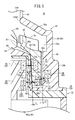
- FIG. 2 is a sectional view taken along line II-II of FIG. 1 showing a separated state of the pump main body and the driving device of the pump device. It is a side sectional view which shows the main part of a pump device.
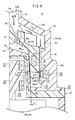
- FIG. 4A is a sectional view taken along line IVA-IVA of FIG. 3 showing a magnetic coupling mechanism.
- FIG. 4B is a sectional view taken along line IVB-IVB of FIG. 3 showing the first and second repulsion mechanisms. It is a side sectional view which shows the dynamic pressure bearing of an impeller and a housing in an enlarged manner.
- FIG. 7A is a schematic explanatory view of the pump device according to the first modification.
- FIG. 7B is a schematic explanatory view of the pump device according to the second modification.
- FIG. 7C is a schematic explanatory view of the pump device according to the third modification.
- the pump device 10 is an artificial heart-lung machine device 12 that assists (or substitutes for) the cardiopulmonary function of a patient, and is a power source for removing blood from the patient and sending blood into the body. Used as a source.
- the pump device 10 is configured as a centrifugal pump having an impeller 14 in the device and flowing a fluid by a centrifugal force accompanying the rotation of the impeller 14.
- the heart-lung machine 12 connects a blood removal tube 16 having a blood removal lumen 16a and a blood feeding tube 18 having a blood feeding lumen 18a to a pump device 10 to form a circulation circuit for circulating blood with a patient. doing.
- the tip opening of the blood removal tube 16 is placed in an appropriate biological organ (for example, the femoral vein), and the tip opening of the blood feeding tube 18 is placed in an appropriate biological organ (for example, the femoral artery). Will be done.
- the pump device 10 sucks the patient's blood through the blood removal lumen 16a and sends the blood to the patient through the blood feeding lumen 18a.
- the artificial heart-lung machine 12 may have a configuration in which a reservoir, an artificial lung, or the like (both not shown) are connected in the middle of a circulation circuit (blood removal tube 16 or blood feeding tube 18) in addition to the pump device 10.
- the pump device 10 includes a pump body 20 accommodating the impeller 14, a drive device 22 for rotating the impeller 14, and a control unit 24 (Controller) for controlling the drive of the drive device 22.
- the housing 26 of the pump device 10 is made of a resin material and can be divided into a main body side housing 28 which constitutes the outer shape of the pump main body 20 and a drive side housing 30 which constitutes the outer shape of the drive device 22.
- the main body side housing 28 and the drive side housing 30 are detachably configured and can be assembled to each other at the time of use, so that the driving force of the driving device 22 can be transmitted to the impeller 14 of the pump main body 20.
- the pump body 20 is removed from the drive device 22 and discarded. That is, the pump body 20 is configured as a disposable type that is replaced after each use and is disposable or sterilized.
- the drive device 22 is configured as a reuse type, and at the next use opportunity, a new pump body 20 is attached to operate the impeller 14 of the pump body 20.
- the main body side housing 28 of the pump main body 20 has an internal space 32 in which the impeller 14 is rotatably accommodated and blood flows in and out.
- the main body side housing 28 has a fixed side box portion 29a formed in a substantially conical shape on the upper side and a disk shape on the lower side, and a fixed side tubular portion 29b formed in a substantially cylindrical shape connected to the fixed side box portion 29a in the lower part. It is composed of a housing unit).
- a blood inflow port 34 connected to the blood removal tube 16 is provided at the ceiling and center of the fixed side box portion 29a. Inside the blood inflow port 34, an inflow path 34a communicating with the internal space 32 is provided. The inflow path 34a communicates with the opening 34a1 provided at the protruding end of the blood inflow port 34 and also communicates with the inflow port 34a2 provided at the boundary with the internal space 32.
- a blood outflow port 36 connected to the blood feeding tube 18 is provided on the outer periphery of the fixed side box portion 29a.
- the blood outflow port 36 projects tangentially from the outer circumference of the fixed side box portion 29a.
- an outflow passage 36a communicating with the internal space 32 is provided inside the blood outflow port 36.
- the outflow passage 36a communicates with the opening 36a1 (see FIG. 1) provided at the protruding end of the blood outflow port 36, and also communicates with the outflow port 36a2 provided at the boundary with the internal space 32.
- the internal space 32 is formed in a shape corresponding to the outer shape of the main body side housing 28 (fixed side box portion 29a, fixed side tubular portion 29b).
- the upper side of the internal space 32 (hereinafter referred to as the upper space 32a) is formed by the inner surface of the fixed side box portion 29a, and the fin portion 60 of the impeller 14 is arranged.
- the lower central portion of the upper space 32a is composed of a shaft-shaped portion 38 of the main body side housing 28 protruding toward the inflow port 34a2 of the blood inflow port 34.
- the fixed-side tubular portion 29b of the main body-side housing 28 has a cylindrical outer peripheral wall 40, a bottom wall 42 forming a lower end portion of the main body-side housing 28, and the above-mentioned axial-shaped portion 38 provided inside the outer peripheral wall 40. And include.
- the lower side of the internal space 32 (hereinafter referred to as the lower space 32b) is formed in a cylindrical shape by the inner surface of the fixed side tubular portion 29b, and rotatably accommodates the driven rotating structure portion 62 of the impeller 14 described later.
- first repulsive magnet 44 is provided near the lower part of the outer peripheral wall 40.
- the first repulsive magnet 44 forms a first repulsive mechanism 86 that repels each other with the impeller-side repulsive magnet 76 provided on the impeller 14.
- the first repulsion mechanism 86 will be described later.
- the shaft-shaped portion 38 provided inside the fixed-side tubular portion 29b has a cylindrical inner peripheral wall 48 and a chevron portion 50 connected to the upper end portion of the inner peripheral wall 48, and the inner peripheral wall 48 and the chevron portion 50.
- An insertion hole 52 is formed inside. That is, the lower space 32b orbits the side of the insertion hole 52. The lower end side of the insertion hole 52 is opened, and the drive side housing 30 is inserted when the pump body 20 and the drive device 22 are assembled.
- the chevron portion 50 of the shaft-shaped portion 38 is formed in a conical shape, and a bearing portion 54 that rotatably supports the impeller 14 is provided at the top thereof.
- the bearing portion 54 is formed in a hemispherical shape and supports the lower side of the rotating shaft body 68 provided in the center of the impeller 14. When the line passing through the hemispherical center and the apex is extended, the bearing portion 54 overlaps the center of the inflow port 34a2 of the blood inflow port 34, and this center is the main body side housing 28 (shaft-shaped portion 38, outer peripheral wall 40). It also coincides with the axis St of.
- the impeller 14 is formed in a cylindrical shape and is accommodated in both the upper space 32a and the lower space 32b in the main body side housing 28.
- the impeller 14 has a fin portion 60 at the upper part and a driven rotating structure portion 62 at the lower part. Inside the fin portion 60 and the driven rotating structure portion 62, a space portion 64 in which the shaft-shaped portion 38 is arranged is formed.
- the fin portion 60 generates a centrifugal force in the blood in the upper space 32a when the impeller 14 rotates.
- the fin portion 60 includes a conical wall portion 66 connected to the upper end of the driven rotating structure portion 62, a rotating shaft body 68 pivotally supported by the bearing portion 54 at the center of the conical wall portion 66, and an upward direction from the upper surface of the conical wall portion 66. It is provided with a plurality of protruding wall portions 70 that project to the surface.
- the space surrounded by the conical wall portion 66 and the pair of protruding wall portions 70 is a flow passage 60a in which the upper portion is open and blood flows.
- the shape of the fin portion 60 is not limited to this, and for example, a shroud (not shown) may be provided on the upper portion of the protruding wall portion 70 to cover the flow passage 60a.
- the conical wall portion 66 is steeper than the chevron portion 50 of the main body side housing 28, and its upper surface is curved in an arch shape. Therefore, a gap (hereinafter referred to as an upper gap 66a) is formed between the chevron portion 50 and the conical wall portion 66.
- the conical wall portion 66 around the rotating shaft body 68 is provided with a plurality of (three) washout holes 67 penetrating the conical wall portion 66.
- the washout hole 67 is formed as an elongated hole long in the circumferential direction, and allows blood to flow through the upper space 32a above the conical wall portion 66 and the upper gap 66a.
- the rotating shaft body 68 is formed in a conical shape that smoothly connects to the conical wall portion 66 and is steeply inclined upward from the protruding wall portion 70.
- the outer periphery of the lower side of the rotating shaft body 68 projects downward and inward in an arc shape, and a concave receiving portion 69 recessed upward is provided in the lower central portion of the rotating shaft body 68.
- the concave receiving portion 69 is formed on an arc concave surface having a curvature smaller than that of the hemispherical bearing portion 54, and comes into contact with the bearing portion 54 when the impeller 14 is not rotating.
- the lower end surface of the movable side tubular portion 72 is separated from the bottom wall 42 of the main body side housing 28 even when the concave receiving portion 69 and the bearing portion 54 are in contact with each other. Further, the concave receiving portion 69 rises from the bearing portion 54 as the impeller 14 rotates.
- the bearing structure of the impeller 14 and the main body side housing 28 is not limited to the above configuration, and various configurations may be adopted.
- the bearing structure may have a configuration in which a pin (not shown) is provided in the center of the main body side housing 28, while a hole (not shown) into which the pin is inserted is provided in the impeller 14.
- the plurality of protruding wall portions 70 of the fin portion 60 extend from the position near the outside of the washout hole 67 to the vicinity of the outer edge of the conical wall portion 66.
- Each protruding wall portion 70 is slightly curved and extends in a plan view. As a result, each protruding wall portion 70 smoothly flows the blood that has entered the flow passage 60a radially outward when the impeller 14 rotates.
- the driven rotating structure portion 62 of the impeller 14 is connected to the conical wall portion 66 of the fin portion 60, and has a cylindrical movable side cylinder portion 72 having a predetermined thickness in the radial direction of the impeller 14.
- the diameter of the movable side cylinder portion 72 is set, for example, in the range of 20 mm to 50 mm. In this embodiment, an impeller 14 having a diameter of 30 mm is applied.
- the movable side cylinder portion 72 has a side peripheral surface (inner peripheral surface 72a, outer peripheral surface 72b) extending parallel to the axial center Si of the impeller 14.
- a driven magnet 74 and an impeller side repulsive magnet 76 are installed inside the movable side cylinder portion 72.
- the driven magnet 74 is arranged at the same height as the driving magnet 92 of the driving device 22 with the pump body 20 and the driving device 22 mounted, and forms a magnetic coupling mechanism 84 with the driving magnet 92. More specifically, the driven magnet 74 is fixed on the upper side of the movable side tubular portion 72 toward the inner side in the radial direction (inner peripheral surface 72a). Further, the axial length (thickness) parallel to the axial center of the driven magnet 74 is set to be substantially the same as the axial length of the driving magnet 92.
- the driven magnet 74 is configured as a driven side multi-pole magnetizing ring magnet 75 that orbits with a constant radius R1 with respect to the axial center Si of the impeller 14.
- the driven side multi-pole magnetizing ring magnet 75 is magnetized so that a plurality of N poles and S poles are alternately arranged along the circumferential direction.
- Examples of the material constituting the driven magnet 74 (driven side multi-pole magnetizing ring magnet 75) include hard magnetic materials such as alnico, ferrite, and neodymium.
- the number of polarities of the driven side multi-pole magnetizing ring magnet 75 is 6 (that is, 3 counter-poles) in FIG. 4A, but is not limited to this.
- the driven magnet 74 is not limited to being configured as a multi-pole magnetizing ring, and is formed in a ring shape by arranging a plurality of arc-shaped magnets having counter poles (N pole, S pole) in the circumferential direction. You may be.
- the impeller-side repulsive magnet 76 is fixed to the lower side of the driven rotating structure portion 62 slightly toward the outer side (outer peripheral surface 72b) in the radial direction. That is, the radius R2 of the impeller side repulsive magnet 76 is longer than the radius R1 of the driven magnet 74. Further, the driven magnet 74 and the impeller side repulsive magnet 76 are largely separated vertically in the driven rotating structure portion 62 so as to suppress the influence of mutual magnetic fields. A shield portion (not shown) that limits the influence of mutual magnetic fields may be provided between the driven magnet 74 and the impeller side repulsive magnet 76.
- the impeller side repulsive magnet 76 is configured as an impeller side inner and outer peripheral unipolar magnetizing ring magnet 77 that orbits with a constant radius R2 from the axis Si of the impeller 14.
- the inner outer peripheral single-pole magnetizing ring magnet 77 on the impeller side has a first polarity (S pole in FIG. 3) over the entire circumference of the outer peripheral portion, and has a second polarity opposite to the first polarity over the entire circumference of the inner peripheral portion. It is magnetized so as to have (N pole in FIG. 3).
- the material constituting the impeller-side repulsive magnet 76 is not particularly limited, and the material mentioned in the driven magnet 74 can be applied.
- the first repulsive magnet 44 is installed on the outer peripheral wall 40 of the fixed side tubular portion 29b facing the driven rotating structure portion 62 of the impeller 14.
- the first repulsive magnet 44 is arranged radially outside and slightly above the impeller side repulsive magnet 76 (position offset in the direction approaching the inflow port 34a2).
- the lower end of the first repulsive magnet 44 is located above the upper end of the impeller side repulsive magnet 76.
- the first repulsive magnet 44 is configured as an outer inner and outer peripheral unipolar magnetizing ring magnet 45 that orbits a position farthest from the axial center St of the main body side housing 28 with a constant radius R3.
- the outer inner and outer peripheral unipolar magnetizing ring magnet 45 has a first polarity (N pole in FIG. 3) over the entire circumference of the outer peripheral portion, and has a second polarity (opposite to the first polarity) over the entire circumference of the inner peripheral portion. In FIG. 3, it is magnetized so as to have an S pole).
- the material constituting the first repulsive magnet 44 is not particularly limited, and the material mentioned in the driven magnet 74 can be applied.
- the impeller-side repulsive magnet 76 and the first repulsive magnet 44 formed on the inflow port 34a2 side of the impeller-side repulsive magnet 76 are the impeller-side repulsive magnet 76 radially inward and downward with respect to the first repulsive magnet 44.
- the repulsive force of the first repulsive mechanism 86 is set to be larger than the attractive force of the magnetic coupling mechanism 84 when the axial center Si of the impeller 14 matches the axial center St of the main body side housing 28.
- the inner peripheral surface 72a of the movable side tubular portion 72 of the impeller 14 and the facing surface 48a of the inner peripheral wall 48 of the housing 26 (main body side housing 28) are dynamically pressured based on the rotation of the impeller 14.
- the bearing 78 is formed.
- the dynamic pressure bearing 78 is a journal bearing that makes the movable side cylinder portion 72 non-contact from the inner peripheral wall 48 by the blood flowing between the facing surface 48a and the inner peripheral surface 72a during the rotation of the impeller 14.
- the dynamic pressure gap (first gap 80 between the facing surface 48a and the inner peripheral surface 72a) of the dynamic pressure bearing 78 is the outer peripheral surface 72b (side circumference) of the movable side cylinder portion 72. It is set sufficiently smaller than the second gap 82 between the surface) and the facing surface 40a of the main body side housing 28 (outer peripheral wall 40).
- the interval I1 of the first gap 80 when the impeller 14 is not rotated is set in the range of 50 ⁇ m to 200 ⁇ m when the fluid is blood, for example, although it depends on the viscosity of the flowing fluid.
- the distance I2 of the second gap 82 is set in the range of, for example, 0.8 mm to 1.2 mm.
- the facing surface 48a and the inner peripheral surface 72a (first gap 80) according to the present embodiment are formed so as to be inclined with respect to the axial centers Si and St of the impeller 14 and the axial portion 38. That is, the facing surface 48a and the inner peripheral surface 72a are formed in a tapered shape that is inclined inward in the radial direction toward the inflow port 34a2, and extend in parallel with each other.
- the facing surface 48a and the inner peripheral surface 72a formed in a tapered shape in this way increase the distance I1 of the first gap 80 by ascending the impeller 14 with the dynamic pressure of the impeller 14 during high-speed rotation.
- the facing surface 40a and the outer peripheral surface 72b forming the second gap 82 extend parallel to the axial centers Si and St.
- the inclination angle ⁇ of the facing surface 48a and the inner peripheral surface 72a with respect to the axial center Si and St is set in the range of, for example, about 0.05 ° to 0.1 °, although it depends on the dimensions of the impeller 14 and the housing 26. It is good.
- the inclination angle ⁇ in this way, for example, when the impeller 14 floats 1 mm from the position when the rotation is stopped, the interval I1 of the first gap 80 can be widened by 50 ⁇ m. If the inclination angle ⁇ is smaller than 0.05 °, the distance I1 of the first gap 80 does not change even if the impeller 14 floats.
- the length of the inner peripheral surface 72a and the facing surface 48a facing each other while inclining each other is preferably set in the range of 10 mm to 100 mm. As a result, even if the impeller 14 floats, an appropriate dynamic pressure can be stably obtained.
- the drive device 22 of the pump device 10 includes a drive-side housing 30 and a motor mechanism 90 housed in the drive-side housing 30. Further, the drive device 22 has a drive magnet 92 and a second repulsion magnet 100 provided in the motor mechanism 90 and attracted to and from the impeller 14.
- the drive-side housing 30 has an annular mounting groove 94 on the upper surface for mounting the pump main body 20 (main body-side housing 28). Further, the portion inside the drive-side housing 30 in the radial direction from the mounting groove 94 is a central convex portion 96 inserted into the insertion hole 52 of the main body-side housing 28.
- the main body side housing 28 of the pump main body 20 and the drive side housing 30 of the drive device 22 are engaged by inserting the central convex portion 96 into the insertion hole 52 while inserting the bottom wall 42 into the mounting groove 94. .. Needless to say, the engagement structure between the pump body 20 and the drive device 22 is not particularly limited.
- a motor body 90a of the motor mechanism 90 is provided inside the drive-side housing 30, and the motor body 90a rotates the rotating body 98 at an appropriate rotation speed under the control of the control unit 24.
- the rotating body 98 protrudes from the motor body 90a and is inserted into the protruding space in the central convex portion 96, and the upper portion thereof bulges outward in the radial direction.
- the pump body 20 and the drive device 22 are mounted, the axis Si of the impeller 14 and the axis Ss of the rotating body 98 overlap each other.
- the upper part of the rotating body 98 is cut out in the upper part and the lower part of the outer peripheral surface on the outer side in the radial direction in a side sectional view, and the driving magnet 92 and the second repulsive magnet 100 are held in this part.
- the drive magnet 92 is fixed to the protruding end of the rotating body 98
- the second repulsive magnet 100 is fixed to the lower part of the bulging portion of the rotating body 98.
- the drive magnet 92 and the second repulsion magnet 100 rotate integrally with the rotating body 98.
- the drive magnet 92 is configured as a drive-side multi-pole magnetizing ring magnet 93 that orbits with a radius R4 shorter than the radius R1 of the driven magnet 74 with respect to the axial center Ss of the rotating body 98.
- the drive-side multi-pole magnetizing ring magnet 93 is magnetized so that a plurality of (six) polarities (N-pole and S-pole) are alternately arranged along the circumferential direction. ..
- the drive magnet 92 is arranged to face the driven magnet 74 on the radial inside of the driven magnet 74 with the pump body 20 and the drive device 22 mounted, thereby forming a magnetic coupling mechanism 84 between the driven magnet 92 and the driven magnet 74. To do.
- the material mentioned in the driven magnet 74 can be appropriately selected.
- the drive magnet 92 is not limited to being composed of a multi-pole magnetizing ring magnet, and is formed in a ring shape by arranging a plurality of arc-shaped magnets having counter poles (N pole, S pole) in the circumferential direction. It may have been done.
- the second repulsive magnet 100 forms a second repulsive mechanism 88 that repels each other with the impeller side repulsive magnet 76.
- the second repulsive magnet 100 is composed of an inner inner peripheral unipolar magnetizing ring magnet 101 that orbits the axial center Ss of the rotating body 98 with the same radius R4 as the driving magnet 92.
- the inner and outer peripheral unipolar magnetizing ring magnet 101 has a first polarity (N pole in FIG. 3) over the entire circumference of the outer peripheral portion, and has a second polarity (opposite to the first polarity) over the entire circumference of the inner peripheral portion. In FIG. 3, it is magnetized so as to have an S pole).
- the material constituting the second repulsive magnet 100 is not particularly limited, and the material mentioned in the driven magnet 74 can be applied.
- the first repulsive magnet 44, the impeller side repulsive magnet 76, and the second repulsive magnet 100 are not limited to being configured as a unipolar magnetizing ring, and have an arcuate shape having opposite poles on the inner peripheral portion and the outer peripheral portion.
- a plurality of magnets may be arranged in the circumferential direction to form a ring.
- the second repulsive magnet 100 is arranged slightly below the impeller side repulsive magnet 76 (at a position offset in the direction away from the inflow port 34a2) with the pump body 20 and the drive device 22 mounted. Therefore, the impeller-side repulsive magnet 76 and the second repulsive magnet 100 generate a repulsive force (repulsive force) that pushes out the impeller-side repulsive magnet 76 on the radial side of the second repulsive magnet 100 and on the inflow port 34a2 side.
- the first distance D1 (shortest distance) between the impeller side repulsive magnet 76 and the first repulsive magnet 44 is shorter than the second distance D2 (shortest distance) between the impeller side repulsive magnet 76 and the second repulsive magnet 100.
- the axial length of the second repulsive magnet 100 is formed longer than the axial length of the first repulsive magnet 44, and a large magnetic flux density is generated with the impeller side repulsive magnet 76.
- the second repulsion mechanism 88 configured in this way applies an upward repulsive force to the impeller 14 when the rotation of the impeller 14 is stopped, but the first repulsion mechanism 86 does not cause the impeller 14 to rise significantly from the bearing portion 54. Balanced to.
- control unit 24 of the pump device 10 is composed of a well-known computer having an input / output interface (not shown), a memory, and a processor, and controls the drive of the motor mechanism 90.
- a monitor, a speaker, an operation button, and the like are provided on the outer surface of the control unit 24, and a user such as a doctor or a nurse sets the drive content of the pump device 10 by operating the operation button.
- the control unit 24 controls the power supply of the battery based on the user's setting information, and rotates the rotating body 98 in the range of, for example, 0 to 10000 rpm.
- the pump device 10 is basically configured as described above, and its operation will be described below.
- the heart-lung machine 12 including the pump device 10 is constructed for a patient who assists cardiopulmonary function.
- the user connects the blood removal tube 16 to the blood inflow port 34 of the pump body 20 and the blood supply tube 18 to the blood outflow port 36 of the pump body 20.
- the first repulsive magnet 44 of the pump main body 20 and the impeller side repulsive magnet 76 form a first repulsive mechanism 86 that repels each other. Therefore, in the pump main body 20 alone, the impeller 14 is pressed in the direction away from the inflow port 34a2 of the main body side housing 28, and the rotating shaft body 68 of the impeller 14 is suppressed from being displaced from the bearing portion 54 when being carried.
- the pump device 10 is assembled by attaching the pump body 20 to the drive device 22.
- the driven magnet 74 and the driving magnet 92 adjacent in the radial direction form a magnetic coupling mechanism 84 with different polarities facing each other.
- the magnetic coupling mechanism 84 generates a magnetic coupling force so that the rotational force of the rotating body 98 can be transmitted to the impeller 14.
- the impeller-side repulsive magnet 76 of the impeller 14 and the second repulsive magnet 100 of the drive device 22 form a second repulsive mechanism 88 that repels each other. That is, in the housing 26, the first repulsion mechanism 86 applies an even repulsive force from the outer side of the impeller 14 to the inner side and the entire circumferential direction, and the second repulsion mechanism 88 is lateral to the inner side of the impeller 14. An even repulsive force is applied from the outside to the entire circumferential direction. Therefore, the impeller 14 receives a repulsive force from the inside and outside of the entire circumferential direction, and the posture is corrected so that the axis Si of the impeller 14 coincides with the axis St of the main body side housing 28.
- the second repulsive magnet 100 pushes out the impeller side repulsive magnet 76 so as to be outward and upward (direction approaching the inflow port 34a2). Therefore, the concave receiving portion 69 of the impeller 14 is likely to be lifted from the bearing portion 54.
- the impeller 14 is in contact with the bearing portion 54 in the mounted state and when the rotation is stopped, but the impeller 14 is not limited to this, and the second repulsion is made so that the impeller 14 floats slightly from the bearing portion 54 when the rotation is stopped.
- the repulsive force of the mechanism 88 may be set.
- the blood flowing into the internal space 32 from the inflow path 34a wraps around from the radial outside of the upper space 32a to the lower space 32b.
- the diameter is on the lower end side of the lower space 32b (between the lower end surface of the movable side cylinder portion 72 and the bottom wall 42). Head inward.
- the blood flows upward through the first gap 80 between the axial portion 38 and the driven rotating structure portion 62, reaches the upper gap 66a, and returns to the upper space 32a via the washout hole 67.
- the dynamic pressure bearing 78 When the impeller 14 rotates, the dynamic pressure bearing 78 is formed by the blood flowing in the first gap 80.
- the dynamic pressure bearing 78 maintains the non-contact property of the impeller 14 with respect to the shaft-shaped portion 38 by generating dynamic pressure in the radial direction, and the axial center Si of the impeller 14 is set to the axial center St of the main body side housing 28. Match.
- the pressure on the outlet 36a2 side of the internal space 32 decreases as the blood flows out from the outflow passage 36a.
- the posture of the axis Si of the impeller 14 is aligned with the axis St by the first and second repulsion mechanisms 86 and 88 and the dynamic pressure bearing 78, so that the vicinity of the outflow port 36a2 is located. It is possible to suppress the lowering posture change and allow blood to flow well.
- the impeller 14 may rise more than necessary by receiving the repulsive force of the first repulsion mechanism 86 (first repulsion magnet 44). Be restricted.
- the impeller 14 rotates at high speed (for example, rotation of 3000 rpm or more), the impeller 14 floats toward the inflow port 34a2, so that the distance I1 between the first gap 80 between the facing surface 48a and the inner peripheral surface 72a expands and the distance I1' It becomes. Therefore, the shearing force generated in the first gap 80 due to the high-speed rotation of the impeller 14 can be suppressed. Therefore, it is possible to significantly reduce hemolysis that is likely to occur due to shearing force.
- the present invention is not limited to the above embodiment, and various modifications can be made according to the gist of the invention.
- the facing surface 48a of the housing 26 and the inner peripheral surface 72a of the impeller 14 are tilted at the same inclination angle ⁇ so that they are parallel to each other, and the first gap 80 is set to a constant interval.
- the facing surface 48a forming the dynamic pressure bearing 78 and the inner peripheral surface 72a may be set to different inclination angles ⁇ (that is, the facing surface 48a and the inner peripheral surface 72a are not parallel to each other). May be good).
- the inclination angle ⁇ of the facing surface 48a with respect to the axial center Si is set to be larger than the inclination angle ⁇ of the inner peripheral surface 72a, so that the distance I1 of the first gap 80 is further widened when the impeller 14 is ascended. Can be done.
- the pump device 10 may be configured not to include one or both of the first and second repulsion mechanisms 86 and 88.
- the pump device 10 may be configured not to include one or both of the first and second repulsion mechanisms 86 and 88.
- the installation positions of the first repulsive magnet 44 and the second repulsive magnet 100 are not particularly limited.
- the first repulsive magnet 44 may be provided not only in the pump main body 20 (main body side housing 28) but also in the drive device 22 (drive side housing 30).
- the second repulsive magnet 100 may be provided not only in the drive device 22 (rotating body 98) but also in the pump main body 20 (main body side housing 28).
- the inner peripheral surface 72a of the movable side tubular portion 72 of the impeller 14 is inclined with respect to the axial center Si, while the fixed side tubular portion 29b of the housing 26.
- the facing surface 48a of the above is parallel to the axis Si.
- the facing surface 48a of the fixed side tubular portion 29b of the housing 26 is inclined with respect to the axial center Si, while the movable side tubular portion 72 of the impeller 14
- the inner peripheral surface 72a is parallel to the axial center Si.
- the facing surface 40a of the outer peripheral wall 40 of the housing 26 (fixed side cylinder portion 29b) and the outer peripheral surface 72b of the movable side cylinder portion 72 of the impeller 14 ( The dynamic pressure bearing 79 is formed in the second gap 82 between the side peripheral surface).
- the facing surface 40a and the outer peripheral surface 72b are formed in a tapered shape inclined with respect to the axial center Si. Specifically, the facing surface 40a and the outer peripheral surface 72b are inclined so as to spread outward in the radial direction toward the inflow port 34a2.
- the dynamic pressure bearing 79 is formed on the radial outer side of the impeller 14, and the dynamic pressure bearing 79 is inclined so that the distance I2 of the dynamic pressure gap (second gap 82) when the impeller 14 floats. Can be expanded. Therefore, the same effect as that of the pump device 10 can be obtained.
- the dynamic pressure bearing 79 formed on the outer side of the impeller 14 in the radial direction may also have a configuration in which only one of the facing surface 40a and the outer peripheral surface 72b is inclined as in the first and second modifications.
- One aspect of the present invention is a pump device 10, 10A to 10C including an impeller 14 and a housing 26 for rotatably accommodating the impeller 14, wherein the impeller 14 is on the opposite side of the fin portion 60 and the fin portion 60.
- the housing 26 includes a housing portion (fixed side cylinder portion 29b) for accommodating the movable side cylinder portion 72, and the housing 26 has a side peripheral surface (inner peripheral surface 72a) of the movable side cylinder portion 72.
- a dynamic pressure gap (first gap 80, first gap 80, first gap 80, 2 Gap 82) is formed, and at least one of the side peripheral surfaces and the facing surfaces 40a and 48a is inclined with respect to the axial center Si of the impeller 14, so that the impeller 14 is rotated as the impeller 14 rotates.
- the dynamic pressure gap widens when ascending.
- the impeller 14 has a dynamic pressure gap (first gap 80, second gap 82) between the side peripheral surfaces (inner peripheral surface 72a, outer peripheral surface 72b) and the facing surfaces 40a and 48a.
- the impeller 14 can be stably rotated by the dynamic pressure during rotation.
- the dynamic pressure gap is widened when the impeller 14 floats due to the dynamic pressure, and the dynamic pressure is increased.
- the shearing force of the gap can be suppressed.
- the pump devices 10, 10A to 10C can satisfactorily flow the fluid, and for example, when the fluid flowing in the housing 26 is blood, it is possible to significantly reduce the occurrence of hemolysis due to shearing force. Become.
- the side peripheral surfaces (inner peripheral surface 72a, outer peripheral surface 72b) and the facing surfaces 40a and 48a are inclined in parallel with each other.
- the pump devices 10 and 10C can have a constant interval while inclining the dynamic pressure gaps (first gap 80, second gap 82) along the axial direction of the impeller 14. Therefore, the pump devices 10 and 10C can suppress the shearing force while maintaining a good rotational posture by the dynamic pressure even if the impeller 14 floats.
- the dynamic pressure gap (first gap 80) is formed inside the movable side cylinder portion 72.
- the pump devices 10, 10A, and 10B can smoothly guide the fluid flowing on the outside of the movable side cylinder portion 72 to the dynamic pressure gap on the inside, and sufficiently exert the dynamic pressure in the dynamic pressure gap.
- the impeller 14 can be rotated stably.
- the inclined side peripheral surfaces (inner peripheral surface 72a, outer peripheral surface 72b) and the facing surfaces 40a and 48a have an inclination angle ⁇ of the impeller 14 with respect to the axial center Si in the range of 0.05 ° to 0.1 °. It is set.
- the pump devices 10, 10A to 10C can appropriately widen the distance between the dynamic pressure gaps (first gap 80, second gap 82) when the impeller 14 rises with rotation, and the shearing force. Can be effectively suppressed.
- the distance between the dynamic pressure gaps (first gap 80, second gap 82) is set in the range of 50 ⁇ m to 200 ⁇ m.
- the pump devices 10, 10A to 10C can stably support and rotate the impeller 14 by the dynamic pressure bearings 78 and 79 formed between the housing 26 and the impeller 14.
- the housing 26 has a hemispherical bearing portion 54
- the impeller 14 has a concave receiving portion 69 that rises from the bearing portion 54 during rotation while contacting the bearing portion 54 when the rotation is stopped.
- the pump devices 10, 10A to 10C can easily raise the impeller 14 when the impeller 14 rotates, and can suppress the occurrence of hemolysis between the bearing portion 54 and the concave receiving portion 69. ..
- the impeller 14 includes a ring-shaped impeller-side repulsive magnet 76 along the circumferential direction of the movable-side tubular portion 72, and the housing 26 has a fixed-side repulsive magnet (th) that repels each other with the impeller-side repulsive magnet 76. It includes one repulsive magnet 44 and a second repulsive magnet 100).
- the pump devices 10, 10A to 10C repel each other between the impeller side repulsive magnet 76 and the fixed side repulsive magnet, and the impeller 14 can be rotated more stably by the repulsive mechanism and the dynamic pressure gap.
Abstract
ポンプ装置(10)は、インペラ(14)と、インペラ(14)を回転自在に収容するハウジング(26)とを備える。インペラ(14)は、フィン部(60)と、可動側筒部(72)とを備え、ハウジング(26)は、可動側筒部(72)を収容する固定側筒部(29b)を備える。可動側筒部(72)の内周面(72a)と、当該内周面(72a)に対向する対向面(48a)との間には第1隙間(80)が形成される。内周面(72a)及び対向面(48a)が、インペラ(14)の軸心(Si)に対して傾斜していることで、インペラ(14)の回転に伴い当該インペラ(14)が浮上した際に第1隙間(80)が広がる。
Description
本発明は、流体を流動させるポンプ装置に関する。
患者の血液(流体)を流動させる人工心肺装置において、ポンプ装置は血液循環の動力源として使用される。例えば、特開2012-21413号公報には、ハウジング内に設けられたインペラを回転させ、この回転に伴う遠心力によりハウジング内に血液を引き込むと共に、ハウジングから血液を吐出する遠心式ポンプ装置が開示されている。
特開2012-21413号公報に開示のポンプ装置は、モータ室とインペラの間で磁気カップリングを形成して、インペラの磁石(永久磁石)を下側に吸引しつつインペラを回転させる。また、このポンプ装置は、インペラの上下において対向するハウジングの対向面に動圧溝を各々備える。これにより、インペラの上下において動圧力が発生してインペラが釣り合った状態で回転する。
ところで、この種のポンプ装置は、インペラを高速に回転させた際に、動圧力を発生させる動圧隙間のせん断力が増加することになる。このようにせん断力が増加すると、血液の溶血が増える傾向がある。
本発明は、上記のポンプ装置の技術に関連してなされたものであり、簡単な構成によって動圧隙間のせん断力を抑制することで、流体を良好に流動させることができるポンプ装置を提供することを目的とする。
前記の目的を達成するために、本発明の一態様は、インペラと、前記インペラを回転自在に収容するハウジングとを備えるポンプ装置であって、前記インペラは、フィン部と、前記フィン部の反対側に設けられる可動側筒部とを備え、前記ハウジングは、前記可動側筒部を収容する収容部を備え、前記可動側筒部の側周面と、当該側周面に対向する前記収容部の対向面との間には、前記インペラの回転時に径方向の動圧力を生じる動圧隙間が形成され、且つ前記側周面及び前記対向面のうち少なくとも一方が、前記インペラの軸心に対して傾斜していることで、前記インペラの回転に伴い当該インペラが浮上した際に前記動圧隙間が広がる。
上記のポンプ装置は、側周面と対向面の間の動圧隙間により、インペラの回転時の動圧力によりインペラを安定的に回転させることができる。しかも、ポンプ装置は、側周面及び対向面のうち少なくとも一方が傾斜していることで、動圧力によりインペラが浮上した際に動圧隙間が広がり、動圧隙間のせん断力を抑制することができる。これによりポンプ装置は、流体を良好に流動させることができ、例えば、ハウジング内に流れる流体が血液の場合に、せん断力による溶血の発生を大幅に低減することが可能となる。
以下、本発明について好適な実施形態を挙げ、添付の図面を参照して詳細に説明する。
本発明の一実施形態に係るポンプ装置10は、患者の心肺機能を補助する(又は心肺を代替する)人工心肺装置12において、患者の血液を体外に脱血させ、また体内に送血する動力源として用いられる。図1に示すように、ポンプ装置10は、インペラ14を装置内に有し、インペラ14の回転に伴う遠心力によって流体を流動させる遠心ポンプに構成されている。
人工心肺装置12は、脱血ルーメン16aを有する脱血チューブ16、及び送血ルーメン18aを有する送血チューブ18をポンプ装置10に接続して、患者との間で血液を循環する循環回路を形成している。人工心肺装置12の構築時には、脱血チューブ16の先端開口が適宜の生体器官(例えば、大腿静脈)に留置され、送血チューブ18の先端開口が適宜の生体器官(例えば、大腿動脈)に留置される。そしてポンプ装置10は、脱血ルーメン16aを通して患者の血液を吸引し、送血ルーメン18aを通して患者に血液を送血する。なお、人工心肺装置12は、ポンプ装置10の他にリザーバ、人工肺等(共に不図示)を循環回路(脱血チューブ16や送血チューブ18)の途中位置に接続した構成でもよい。
図2に示すように、ポンプ装置10は、上記のインペラ14を収容したポンプ本体20と、インペラ14を回転させる駆動装置22と、駆動装置22の駆動を制御する制御部24(Controller)とを備える。ポンプ装置10のハウジング26は、樹脂材料からなり、ポンプ本体20の外形を構成する本体側ハウジング28と、駆動装置22の外形を構成する駆動側ハウジング30とに分割可能となっている。
本体側ハウジング28と駆動側ハウジング30とは、着脱自在に構成され、使用時に相互に組み付けられることで、駆動装置22の駆動力がポンプ本体20のインペラ14に伝達可能となる。そして使用後に、ポンプ本体20は駆動装置22から取り外されて廃棄される。つまり、ポンプ本体20は、1回の使用毎に取り替えられて、使い捨て又は滅菌処理されるディスポーザブルタイプに構成される。一方、駆動装置22は、リユースタイプに構成され、次の使用機会において、新たなポンプ本体20が取り付けられてこのポンプ本体20のインペラ14を動作させる。
ポンプ本体20の本体側ハウジング28は、インペラ14が回転自在に収容されると共に、血液の流入及び流出がなされる内部空間32を有する。本体側ハウジング28は、上側が略円錐状且つ下側が円盤状に形成された固定側箱部29aと、この固定側箱部29aに下部に連なり略円筒状に形成された固定側筒部29b(収容部)とで構成される。
固定側箱部29aの天井部且つ中心には、脱血チューブ16に接続される血液流入ポート34が設けられる。血液流入ポート34の内部には、内部空間32に連通する流入路34aが設けられている。流入路34aは、血液流入ポート34の突出端に設けられた開口34a1に連通すると共に、内部空間32との境界に設けられた流入口34a2に連通する。
また、固定側箱部29aの外周には、送血チューブ18に接続される血液流出ポート36が設けられている。血液流出ポート36は、固定側箱部29aの外周から接線方向に突出している。血液流出ポート36の内部には、内部空間32に連通する流出路36aが設けられている。流出路36aは、血液流出ポート36の突出端に設けられた開口36a1(図1参照)に連通すると共に、内部空間32との境界に設けられた流出口36a2に連通する。
図3に示すように、内部空間32は、本体側ハウジング28の外形(固定側箱部29a、固定側筒部29b)に応じた形状に形成されている。内部空間32の上部側(以下、上空間32aという)は、固定側箱部29aの内面により構成され、インペラ14のフィン部60が配置される。また、上空間32aの下部側中心部は、血液流入ポート34の流入口34a2に向かって突出した本体側ハウジング28の軸状部38により構成される。
本体側ハウジング28の固定側筒部29bは、円筒状の外周壁40と、本体側ハウジング28の下端部を構成する底壁42と、外周壁40の内側に設けられた上記の軸状部38とを含む。内部空間32の下部側(以下、下空間32bという)は、この固定側筒部29bの内面により円筒状に形成され、後述するインペラ14の従動回転構造部62を回転自在に収容する。
また、外周壁40の下部寄りには、第1反発磁石44が設けられている。第1反発磁石44は、インペラ14に設けられたインペラ側反発磁石76との間で相互に反発し合う第1反発機構86を形成する。この第1反発機構86については後述する。
固定側筒部29bの内側に設けられる軸状部38は、円筒状の内周壁48と、内周壁48の上端部に連結される山形部50とを有し、内周壁48及び山形部50の内側に挿入穴52を形成している。すなわち下空間32bは、この挿入穴52の側方を周回している。挿入穴52は、下端側が開口し、ポンプ本体20と駆動装置22の組付け時に駆動側ハウジング30が挿入される。
軸状部38の山形部50は、円錐状に形成され、その頂部にはインペラ14を回転自在に軸支する軸受部54が設けられている。軸受部54は、半球状に形成され、インペラ14の中央に設けられた回転軸体68の下側を支持する。軸受部54は、半球状の中心と頂点を通る線を延長した場合に、血液流入ポート34の流入口34a2の中心と重なり、この中心は本体側ハウジング28(軸状部38、外周壁40)の軸心Stとも一致する。
図1及び図3に示すように、インペラ14は、円筒状に形成され、本体側ハウジング28内の上空間32aと下空間32bの両方にわたって収容される。インペラ14は、フィン部60を上部に有すると共に、従動回転構造部62を下部に有する。フィン部60及び従動回転構造部62の内側は、軸状部38が配置される空間部64を形成している。
フィン部60は、インペラ14の回転時に、上空間32aの血液に遠心力を生じさせる。フィン部60は、従動回転構造部62の上端に連なる円錐壁部66と、円錐壁部66の中心で軸受部54に軸支される回転軸体68と、円錐壁部66の上面から上方向に突出する複数の突出壁部70とを備える。円錐壁部66と一対の突出壁部70とで囲われる空間は、上部が開放し血液が流動する流通路60aとなっている。なお、フィン部60の形状は、これに限定されず、例えば、突出壁部70の上部に図示しないシュラウドが設けられ、流通路60aが覆われる構成でもよい。
円錐壁部66は、本体側ハウジング28の山形部50よりも急傾斜し、且つその上面が弓形に湾曲している。そのため、山形部50と円錐壁部66の間には、隙間(以下、上側隙間66aという)が形成される。回転軸体68の周囲の円錐壁部66には、円錐壁部66を貫通する複数(3つ)のウオッシュアウトホール67が設けられている。ウオッシュアウトホール67は、周方向に長い長孔に形成され、円錐壁部66よりも上側の上空間32aと上側隙間66aとを連通して血液を流動させる。
回転軸体68は、円錐壁部66に滑らかに連なると共に、突出壁部70よりも上方に向かって急激に傾斜する円錐状に形成されている。回転軸体68の下部側の外周は、下方且つ内側に向かって円弧状に突出し、また回転軸体68の下部中央部には上方に窪む凹状受部69が設けられている。凹状受部69は、半球状の軸受部54よりも小さな曲率の円弧凹面に形成され、インペラ14の非回転時に軸受部54に接触する。可動側筒部72の下端面は、凹状受部69と軸受部54が接触した状態においても本体側ハウジング28の底壁42から離間している。また凹状受部69はインペラ14の回転に伴い軸受部54から浮上する。
なお、インペラ14と本体側ハウジング28の軸受構造は、上記構成に限定されず種々の構成を採用してよい。例えば、軸受構造は、本体側ハウジング28の中心に図示しないピンを設ける一方で、ピンが挿入される図示しない孔部をインペラ14に設けた構成としてもよい。
フィン部60の複数の突出壁部70は、ウオッシュアウトホール67の外側近傍位置から円錐壁部66の外縁付近まで延在している。各突出壁部70は、平面視で、若干湾曲して延在している。これにより各突出壁部70は、インペラ14の回転時に、流通路60aに入り込んだ血液を径方向外側にスムーズに流動させる。
インペラ14の従動回転構造部62は、フィン部60の円錐壁部66に連なり、インペラ14の径方向に所定の厚みを有する円筒状の可動側筒部72を有する。可動側筒部72の直径は、例えば、20mm~50mmの範囲に設定される。本実施形態では、直径が30mmのインペラ14を適用している。
可動側筒部72は、インペラ14の軸心Siに平行に延在する側周面(内周面72a、外周面72b)を有する。可動側筒部72の内部には、従動磁石74及びインペラ側反発磁石76が設置されている。
従動磁石74は、ポンプ本体20と駆動装置22の装着状態で、駆動装置22の駆動磁石92と同一高さ位置に配置されて、駆動磁石92との間で磁気カップリング機構84を形成する。より具体的には、従動磁石74は、可動側筒部72の上部側で、径方向内側(内周面72a)寄りに固定される。また、従動磁石74の軸心に平行な軸方向長さ(厚さ)は、駆動磁石92の軸方向長さと略同一に設定されている。
図4Aに示すように、従動磁石74は、インペラ14の軸心Siに対し一定の半径R1で周回する従動側多極着磁リング磁石75に構成されている。従動側多極着磁リング磁石75は、複数のN極及びS極が周方向に沿って交互に並ぶように着磁されたものである。従動磁石74(従動側多極着磁リング磁石75)を構成する材料としては、例えば、アルニコ、フェライト、ネオジム等の硬質磁性材料があげられる。なお、従動側多極着磁リング磁石75の極性数は、図4A中において6つ(すなわち3つの対極)であるが、これに限定されるものではない。また、従動磁石74は、多極着磁リングとして構成されることに限定されず、対極(N極、S極)を有する円弧状の磁石を、周方向に複数並べることでリング状に形成されていてもよい。
図3及び図4Bに示すように、インペラ側反発磁石76は、従動回転構造部62の下部側で、若干径方向外側(外周面72b)寄りに固定される。つまり、従動磁石74の半径R1に対しインペラ側反発磁石76の半径R2のほうが長い。また、従動磁石74とインペラ側反発磁石76とは、相互の磁界の影響が抑制されるように従動回転構造部62内で上下に大きく離間している。従動磁石74とインペラ側反発磁石76の間には、相互の磁界の影響を制限するシールド部(不図示)が設けられていてもよい。
インペラ側反発磁石76は、インペラ14の軸心Siから一定の半径R2で周回するインペラ側内外周単極着磁リング磁石77に構成されている。インペラ側内外周単極着磁リング磁石77は、外周部の全周にわたって第1極性(図3中ではS極)を有し、内周部の全周にわたって第1極性と反対の第2極性(図3中ではN極)を有するように着磁されたものである。インペラ側反発磁石76(インペラ側内外周単極着磁リング磁石77)を構成する材料は、特に限定されず、従動磁石74であげた材料を適用し得る。
ここで上記したように、インペラ14の従動回転構造部62に対向する固定側筒部29bの外周壁40には、第1反発磁石44が設置される。第1反発磁石44は、インペラ側反発磁石76よりも径方向外側且つ多少上方(流入口34a2に近づく方向にオフセットした位置)に配置されている。第1反発磁石44の下端は、インペラ側反発磁石76の上端よりも上側に位置している。
第1反発磁石44は、本体側ハウジング28の軸心Stから最も離れた位置を、一定の半径R3で周回する外側内外周単極着磁リング磁石45に構成されている。外側内外周単極着磁リング磁石45は、外周部の全周にわたって第1極性(図3中ではN極)を有し、内周部の全周にわたって第1極性と反対の第2極性(図3中ではS極)を有するように着磁されたものである。この第1反発磁石44を構成する材料も特に限定されず、従動磁石74であげた材料を適用し得る。
インペラ側反発磁石76と、このインペラ側反発磁石76よりも流入口34a2側に形成された第1反発磁石44とは、第1反発磁石44に対し径方向内側且つ下方向にインペラ側反発磁石76を押し出す反発力(斥力)を生じさせる。つまりインペラ14は、第1反発機構86により、流入口34a2から離れる方向に押し付けられると共に、周方向全体から径方向内側に押し付けられる力を受ける。第1反発機構86の反発力は、インペラ14の軸心Siが本体側ハウジング28の軸心Stに一致している場合に、磁気カップリング機構84の引力よりも大きく設定されている。
図2及び図3に戻り、インペラ14の可動側筒部72の内周面72aと、ハウジング26(本体側ハウジング28)の内周壁48の対向面48aとは、インペラ14の回転に基づき動圧軸受78を形成する。動圧軸受78は、インペラ14の回転において、対向面48aと内周面72aの間を流動する血液により、内周壁48から可動側筒部72を非接触とするジャーナル軸受である。
詳細には、図5に示すように、動圧軸受78の動圧隙間(対向面48aと内周面72aの間の第1隙間80)は、可動側筒部72の外周面72b(側周面)と本体側ハウジング28(外周壁40)の対向面40aとの間の第2隙間82よりも充分に小さく設定される。インペラ14の非回転時における第1隙間80の間隔I1は、流動する流体の粘性にもよるが、例えば流体が血液の場合には50μm~200μmの範囲に設定される。なお、第2隙間82の間隔I2は、例えば0.8mm~1.2mmの範囲に設定される。
そして、本実施形態に係る対向面48a及び内周面72a(第1隙間80)は、インペラ14や軸状部38の軸心Si、Stに対して傾斜するように形成されている。すなわち、対向面48a及び内周面72aは、流入口34a2に向かって径方向内側に傾斜するテーパ状に形成され、互いに平行に延在している。このようにテーパ状に形成された対向面48a及び内周面72aは、インペラ14の高速回転時の動圧力に伴いインペラ14が浮上することで、第1隙間80の間隔I1を広げる。なお、第2隙間82を構成する対向面40aと外周面72bは、軸心Si、Stに対して平行に延在している。
軸心Si、Stに対する対向面48a及び内周面72aの傾斜角度θは、インペラ14やハウジング26の寸法にもよるが、例えば、0.05°~0.1°程度の範囲に設定されるとよい。このように傾斜角度θを設定することで、例えば、インペラ14は、回転停止時の位置から1mm浮いた場合に、第1隙間80の間隔I1を50μm広げることができる。仮に、傾斜角度θが0.05°よりも小さい場合には、インペラ14が浮上しても第1隙間80の間隔I1が殆ど変わらなくなる。逆に、傾斜角度θが0.1°よりも大きい場合には、径方向の動圧力が弱まりインペラ14の回転姿勢が不安定となる。またテーパ状の対向面48aと内周面72aは、インペラ14の回転速度の上昇に比例して、第1隙間80の間隔I1をリニアに広げさせる。
インペラ14の非回転時に、内周面72aと対向面48aが相互に傾斜しつつ対向し合う長さは、10mm~100mmの範囲に設定されることが好ましい。これにより、インペラ14が浮上しても適切な動圧力を安定的に得ることができる。
図1~図3に示すように、ポンプ装置10の駆動装置22は、駆動側ハウジング30と、駆動側ハウジング30内に収容されるモータ機構90とを備える。さらに、駆動装置22は、モータ機構90に設けられてインペラ14との間で引き合う駆動磁石92及び第2反発磁石100を有する。
駆動側ハウジング30は、ポンプ本体20(本体側ハウジング28)を装着する円環状の装着溝94を上面に有する。また、駆動側ハウジング30の装着溝94よりも径方向内側部分は、本体側ハウジング28の挿入穴52に挿入される中央凸部96となっている。ポンプ本体20の本体側ハウジング28と、駆動装置22の駆動側ハウジング30とは、挿入穴52に中央凸部96を挿入する一方で、底壁42を装着溝94に挿入することにより係合する。なおポンプ本体20と駆動装置22の係合構造は特に限定されないことは勿論である。
駆動側ハウジング30の内部には、モータ機構90のモータ本体90aが設けられ、モータ本体90aは、制御部24の制御下に回転体98を適宜の回転速度で回転させる。回転体98は、モータ本体90aから突出して中央凸部96内の突出空間に挿入され、その上部が径方向外側に膨出している。ポンプ本体20と駆動装置22の装着状態では、インペラ14の軸心Siと回転体98の軸心Ssが相互に重なる。
回転体98の上部は、側面断面視で、径方向外側の外周面の上部及び下部が切り欠かれ、この部分に駆動磁石92及び第2反発磁石100を保持している。具体的には、回転体98の突出端に駆動磁石92が固定される一方で、回転体98の膨出部分の下部に第2反発磁石100が固定される。駆動磁石92及び第2反発磁石100は、回転体98と一体に回転する。
図4Aに示すように、駆動磁石92は、回転体98の軸心Ssに対し従動磁石74の半径R1よりも短い半径R4で周回する駆動側多極着磁リング磁石93に構成されている。駆動側多極着磁リング磁石93は、従動磁石74と同様に、複数(6つ)の極性(N極、S極)が周方向に沿って交互に並ぶように着磁されたものである。駆動磁石92は、ポンプ本体20と駆動装置22の装着状態で、従動磁石74の径方向内側で従動磁石74に対向配置されることで、従動磁石74との間に磁気カップリング機構84を形成する。
駆動磁石92を構成する材料は、従動磁石74であげた材料を適宜選択し得る。また、駆動磁石92も、多極着磁リング磁石に構成されることに限定されず、対極(N極、S極)を有する円弧状の磁石を、周方向に複数並べることでリング状に形成されていてもよい。
また図4Bに示すように、第2反発磁石100は、インペラ側反発磁石76との間で相互に反発し合う第2反発機構88を形成する。第2反発磁石100は、回転体98の軸心Ssに対し駆動磁石92と同じ半径R4で周回する内側内外周単極着磁リング磁石101に構成されている。内側内外周単極着磁リング磁石101は、外周部の全周にわたって第1極性(図3中ではN極)を有し、内周部の全周にわたって第1極性と反対の第2極性(図3中ではS極)を有するように着磁されたものである。この第2反発磁石100を構成する材料も特に限定されず、従動磁石74であげた材料を適用し得る。
なお、第1反発磁石44、インペラ側反発磁石76、第2反発磁石100は、単極着磁リングとして構成されることに限定されず、内周部と外周部とに対極を有する円弧状の磁石を、周方向に複数並べることでリング状に形成されてもよい。
第2反発磁石100は、ポンプ本体20と駆動装置22の装着状態で、インペラ側反発磁石76よりも若干下方(流入口34a2から離れる方向にオフセットした位置)に配置される。このため、インペラ側反発磁石76と第2反発磁石100とは、第2反発磁石100に対し径方向外側且つ流入口34a2側にインペラ側反発磁石76を押し出す反発力(斥力)を生じさせる。
インペラ側反発磁石76と第1反発磁石44の第1距離D1(最短距離)は、インペラ側反発磁石76と第2反発磁石100の第2距離D2(最短距離)よりも短い。その一方で、第2反発磁石100の軸方向長さは、第1反発磁石44の軸方向長さよりも長く形成され、インペラ側反発磁石76との間で多くの磁束密度を生じさせる。このように構成された第2反発機構88は、インペラ14の回転停止時に、インペラ14に上方向へ向かう反発力をかけるが、第1反発機構86によりインペラ14は軸受部54から大きく浮き上がらない程度にバランスされる。
図2に戻り、ポンプ装置10の制御部24(Controller)は、図示しない入出力インタフェース、メモリ及びプロセッサを有する周知のコンピュータにより構成され、モータ機構90の駆動を制御する。制御部24の外面には、図示しないモニタ、スピーカ、操作ボタン等が設けられており、医師や看護士等のユーザは、操作ボタンを操作することで、ポンプ装置10の駆動内容を設定する。制御部24は、ユーザの設定情報に基づき、バッテリの電力の供給を制御して、例えば0~10000rpmの範囲で回転体98を回転させる。
本実施形態に係るポンプ装置10は、基本的には以上のように構成されるものであり、以下その動作について説明する。
ポンプ装置10を含む人工心肺装置12は、心肺機能を補助する患者に対して構築される。人工心肺装置12の構築時に、ユーザは、ポンプ本体20の血液流入ポート34に脱血チューブ16を接続し、ポンプ本体20の血液流出ポート36に送血チューブ18を接続する。ここで、ポンプ本体20の第1反発磁石44とインペラ側反発磁石76とは、相互に反発し合う第1反発機構86を構成している。このため、ポンプ本体20単体では、本体側ハウジング28の流入口34a2から離れる方向にインペラ14が押し付けられ、持ち運び時等にインペラ14の回転軸体68が軸受部54からずれることが抑制される。
そして図2に示すように、ポンプ装置10は、駆動装置22に対しポンプ本体20を装着することで組み立てられる。装着状態では、図3に示すように、径方向に隣接する従動磁石74と駆動磁石92が、異なる極性同士を相互に対向させて磁気カップリング機構84を形成する。磁気カップリング機構84は、磁気的結合力を生じさせて、回転体98の回転力をインペラ14に伝達可能とする。
さらに装着状態では、インペラ14のインペラ側反発磁石76と駆動装置22の第2反発磁石100とが、相互に反発し合う第2反発機構88を形成する。つまり、ハウジング26内では、第1反発機構86がインペラ14の外側の側方から内側方向且つ周方向全体に均等的な反発力をかけ、第2反発機構88が、インペラ14の内側の側方から外側方向且つ周方向全体に均等的な反発力をかける。従って、インペラ14は、周方向全体の側方の内外から反発力を受け、本体側ハウジング28の軸心Stにインペラ14の軸心Siが一致するように姿勢が矯正される。
また、第2反発磁石100は、外側且つ上方向(流入口34a2に近づく方向)に向かうようにインペラ側反発磁石76を押し出す。このため、インペラ14の凹状受部69は、軸受部54から浮き上がり易くなる。なお本実施形態において、インペラ14は、装着状態且つ回転停止時に軸受部54に接触しているが、これに限定されず、回転停止時にインペラ14が軸受部54から微量に浮くように第2反発機構88の反発力を設定してもよい。
ポンプ装置10は、駆動装置22のモータ機構90が回転体98を回転させると、磁気カップリング機構84を介して本体側ハウジング28内でインペラ14を回転させる。これにより上空間32a内で回転するフィン部60は、遠心力を生じさせて血液を流動させる。
図6に示すように、インペラ14の回転時に、流入路34aから内部空間32に流入した血液は、上空間32aの径方向外側から下空間32bに回り込む。この血液は、外周壁40と従動回転構造部62の間の第2隙間82を下方に流動すると、下空間32bの下端側(可動側筒部72の下端面と底壁42の間)で径方向内側に向かう。さらに血液は、軸状部38と従動回転構造部62との間の第1隙間80を上方に流動して上側隙間66aに至り、ウオッシュアウトホール67を介して上空間32aに戻る。
インペラ14の回転時には、第1隙間80を流動する血液により動圧軸受78が形成される。この動圧軸受78は、径方向に動圧力を生じさせることで、軸状部38に対するインペラ14の非接触性を維持して、インペラ14の軸心Siを本体側ハウジング28の軸心Stに一致させる。
ここで、ポンプ本体20の内部空間32は、流出路36aからの血液の流出に伴い、内部空間32の流出口36a2側の圧力が低くなる。これに対し、ポンプ装置10は、第1及び第2反発機構86、88と、動圧軸受78とによりインペラ14の軸心Siの姿勢を軸心Stに沿わせることで、流出口36a2付近が低くなる姿勢変化を抑制し、血液を良好に流動させることができる。また、インペラ14は、高速回転等に伴い流入口34a2側にインペラ14が浮上しても、第1反発機構86(第1反発磁石44)の反発力を受けることで必要以上に浮上することが制限される。
さらに、インペラ14が高速回転(例えば3000rpm以上の回転)時には、インペラ14が流入口34a2側に浮上することで、対向面48aと内周面72aの第1隙間80の間隔I1が広がり間隔I1’となる。そのため、インペラ14の高速回転に伴って第1隙間80に生じるせん断力を抑制することができる。従ってせん断力により生じ易くなる溶血を大幅に低減することが可能となる。
なお、本発明は、上記の実施形態に限定されず、発明の要旨に沿って種々の改変が可能である。例えば、本実施形態において、ハウジング26の対向面48aとインペラ14の内周面72aとは、同じ傾斜角度θで傾斜することで互いに平行となり、第1隙間80を一定の間隔としている。しかしながら、動圧軸受78を形成する対向面48aと内周面72aとは相互に異なる傾斜角度θに設定されていてもよい(つまり、対向面48aと内周面72aが平行となっていなくてもよい)。例えば、対向面48aの軸心Siに対する傾斜角度θが、内周面72aの傾斜角度θよりも大きく設定されていることで、インペラ14の浮上時に第1隙間80の間隔I1をより大きく広げることができる。
また例えば、ポンプ装置10は、第1及び第2反発機構86、88の一方又は両方を備えない構成でもよい。動圧軸受78の動圧力を適切に設定することで、インペラ14の回転時の姿勢変化を抑制することができる。
さらに、第1反発磁石44、第2反発磁石100の設置位置は特に限定されない。例えば、第1反発磁石44は、ポンプ本体20(本体側ハウジング28)に設けられるだけでなく、駆動装置22(駆動側ハウジング30)に設けられてもよい。逆に、第2反発磁石100は、駆動装置22(回転体98)に設けられるだけでなく、ポンプ本体20(本体側ハウジング28)に設けられてもよい。
以下、本発明の変形例について幾つか例示する。なお、以降の説明において、上記の実施形態と同じ構成又は同じ機能を有する要素には、同じ符号を付してその詳細な説明を省略する。
図7Aに示すように、第1変形例に係るポンプ装置10Aは、インペラ14の可動側筒部72の内周面72aが軸心Siに対し傾斜する一方で、ハウジング26の固定側筒部29bの対向面48aが軸心Siに対し平行となっている。このように、内周面72aが傾斜しているだけでも、インペラ14の浮上に伴い動圧軸受78の第1隙間80の間隔I1を広げることが可能であり、ポンプ装置10と同様の効果を得ることができる。
図7Bに示すように、第2変形例に係るポンプ装置10Bは、ハウジング26の固定側筒部29bの対向面48aが軸心Siに対し傾斜する一方で、インペラ14の可動側筒部72の内周面72aが軸心Siに対し平行となっている。このように、対向面48aが傾斜しているだけでも、インペラ14の浮上に伴い動圧軸受78の第1隙間80の間隔I1を広げることが可能であり、ポンプ装置10と同様の効果を得ることができる。
図7Cに示すように、第3変形例に係るポンプ装置10Cは、ハウジング26(固定側筒部29b)の外周壁40の対向面40aと、インペラ14の可動側筒部72の外周面72b(側周面)との間の第2隙間82において動圧軸受79を構成している。そして、対向面40aと外周面72bが軸心Siに対し傾斜したテーパ状に形成されている。具体的には、対向面40a及び外周面72bは、流入口34a2に向かって径方向外側に広がるように傾斜している。
このようにインペラ14の径方向外側に動圧軸受79を形成し、この動圧軸受79が傾斜していることで、インペラ14が浮上した際に動圧隙間(第2隙間82)の間隔I2を広げることができる。従ってポンプ装置10と同様の効果を得ることができる。なお、インペラ14の径方向外側に形成する動圧軸受79も、第1及び第2変形例のように、対向面40a及び外周面72bのうちいずれか一方のみが傾斜する構成でもよい。
上記の実施形態から把握し得る技術的思想及び効果について、以下に記載する。
本発明の一態様は、インペラ14と、インペラ14を回転自在に収容するハウジング26とを備えるポンプ装置10、10A~10Cであって、インペラ14は、フィン部60と、フィン部60の反対側に設けられる可動側筒部72とを備え、ハウジング26は、可動側筒部72を収容する収容部(固定側筒部29b)を備え、可動側筒部72の側周面(内周面72a、外周面72b)と、当該側周面に対向する収容部の対向面40a、48aとの間には、インペラ14の回転時に径方向の動圧力を生じる動圧隙間(第1隙間80、第2隙間82)が形成され、且つ側周面及び対向面40a、48aのうち少なくとも一方が、インペラ14の軸心Siに対して傾斜していることで、インペラ14の回転に伴い当該インペラ14が浮上した際に動圧隙間が広がる。
ポンプ装置10、10A~10Cは、側周面(内周面72a、外周面72b)と対向面40a、48aの間の動圧隙間(第1隙間80、第2隙間82)により、インペラ14の回転時の動圧力によりインペラ14を安定的に回転させることができる。しかも、ポンプ装置10、10A~10Cは、側周面及び対向面40a、48aのうち少なくとも一方が傾斜していることで、動圧力によりインペラ14が浮上した際に動圧隙間が広がり、動圧隙間のせん断力を抑制することができる。これによりポンプ装置10、10A~10Cは、流体を良好に流動させることができ、例えば、ハウジング26内に流れる流体が血液の場合に、せん断力による溶血の発生を大幅に低減することが可能となる。
また、側周面(内周面72a、外周面72b)及び対向面40a、48aは、互いに平行に傾斜している。これにより、ポンプ装置10、10Cは、インペラ14の軸心方向に沿って動圧隙間(第1隙間80、第2隙間82)を傾斜しつつ一定の間隔とすることができる。従って、ポンプ装置10、10Cは、インペラ14が浮上しても、動圧力により回転姿勢を良好に維持しつつせん断力を抑制することができる。
また、動圧隙間(第1隙間80)は、可動側筒部72の内側に形成される。これにより、ポンプ装置10、10A、10Bは、可動側筒部72の外側を流動した流体を内側の動圧隙間にスムーズに導くことが可能となり、動圧隙間において動圧力を充分に発揮させてインペラ14を安定的に回転させることができる。
また、傾斜している側周面(内周面72a、外周面72b)及び対向面40a、48aは、インペラ14の軸心Siに対する傾斜角度θが0.05°~0.1°の範囲に設定されている。これにより、ポンプ装置10、10A~10Cは、インペラ14が回転に伴って浮上した際に、動圧隙間(第1隙間80、第2隙間82)の間隔を適切に広げることができ、せん断力を効果的に抑制することが可能となる。
また、動圧隙間(第1隙間80、第2隙間82)の間隔は、50μm~200μmの範囲に設定されている。ポンプ装置10、10A~10Cは、ハウジング26とインペラ14の間に形成された動圧軸受78、79により、インペラ14を安定的に軸支して回転させることが可能となる。
また、ハウジング26は、半球状の軸受部54を有し、インペラ14は、回転停止時に軸受部54に接触する一方で、回転時に軸受部54から浮上する凹状受部69を有する。これにより、ポンプ装置10、10A~10Cは、インペラ14の回転時にインペラ14を容易に浮上させることが可能となり、軸受部54と凹状受部69との間の溶血の発生も抑制することができる。
また、インペラ14は、可動側筒部72の周方向に沿ってリング状のインペラ側反発磁石76を備え、ハウジング26は、インペラ側反発磁石76との間で反発し合う固定側反発磁石(第1反発磁石44、第2反発磁石100)を備える。これにより、ポンプ装置10、10A~10Cは、インペラ側反発磁石76と固定側反発磁石の間で反発し合い、反発機構と動圧隙間によってインペラ14をより一層安定的に回転させることができる。
Claims (7)
- インペラと、
前記インペラを回転自在に収容するハウジングとを備えるポンプ装置であって、
前記インペラは、フィン部と、前記フィン部の反対側に設けられる可動側筒部とを備え、
前記ハウジングは、前記可動側筒部を収容する収容部を備え、
前記可動側筒部の側周面と、当該側周面に対向する前記収容部の対向面との間には、前記インペラの回転時に径方向の動圧力を生じる動圧隙間が形成され、
且つ前記側周面及び前記対向面のうち少なくとも一方が、前記インペラの軸心に対して傾斜していることで、前記インペラの回転に伴い当該インペラが浮上した際に前記動圧隙間が広がる
ポンプ装置。 - 請求項1記載のポンプ装置において、
前記側周面及び前記対向面は、互いに平行に傾斜している
ポンプ装置。 - 請求項1又は2記載のポンプ装置において、
前記動圧隙間は、前記可動側筒部の内側に形成される
ポンプ装置。 - 請求項1~3のいずれか1項に記載のポンプ装置において、
傾斜している前記側周面及び前記対向面は、前記インペラの軸心に対する傾斜角度が0.05°~0.1°の範囲に設定されている
ポンプ装置。 - 請求項1~4のいずれか1項に記載のポンプ装置において、
前記動圧隙間の間隔は、50μm~200μmの範囲に設定されている
ポンプ装置。 - 請求項1~5のいずれか1項に記載のポンプ装置において、
前記ハウジングは、半球状の軸受部を有し、
前記インペラは、回転停止時に前記軸受部に接触する一方で、回転時に前記軸受部から浮上する凹状受部を有する
ポンプ装置。 - 請求項1~6のいずれか1項に記載のポンプ装置において、
前記インペラは、前記可動側筒部の周方向に沿ってリング状のインペラ側反発磁石を備え、
前記ハウジングは、前記インペラ側反発磁石との間で反発し合う固定側反発磁石を備える
ポンプ装置。
Priority Applications (2)
| Application Number | Priority Date | Filing Date | Title |
|---|---|---|---|
| JP2021527364A JP7352630B2 (ja) | 2019-06-19 | 2020-03-13 | ポンプ装置 |
| US17/527,224 US20220072296A1 (en) | 2019-06-19 | 2021-11-16 | Pump device for pumping blood |
Applications Claiming Priority (2)
| Application Number | Priority Date | Filing Date | Title |
|---|---|---|---|
| JP2019113877 | 2019-06-19 | ||
| JP2019-113877 | 2019-06-19 |
Related Child Applications (1)
| Application Number | Title | Priority Date | Filing Date |
|---|---|---|---|
| US17/527,224 Continuation US20220072296A1 (en) | 2019-06-19 | 2021-11-16 | Pump device for pumping blood |
Publications (1)
| Publication Number | Publication Date |
|---|---|
| WO2020255499A1 true WO2020255499A1 (ja) | 2020-12-24 |
Family
ID=74040021
Family Applications (1)
| Application Number | Title | Priority Date | Filing Date |
|---|---|---|---|
| PCT/JP2020/011198 WO2020255499A1 (ja) | 2019-06-19 | 2020-03-13 | ポンプ装置 |
Country Status (3)
| Country | Link |
|---|---|
| US (1) | US20220072296A1 (ja) |
| JP (1) | JP7352630B2 (ja) |
| WO (1) | WO2020255499A1 (ja) |
Cited By (1)
| Publication number | Priority date | Publication date | Assignee | Title |
|---|---|---|---|---|
| WO2022185961A1 (ja) * | 2021-03-04 | 2022-09-09 | テルモ株式会社 | ポンプ装置 |
Families Citing this family (4)
| Publication number | Priority date | Publication date | Assignee | Title |
|---|---|---|---|---|
| DE102018201030A1 (de) | 2018-01-24 | 2019-07-25 | Kardion Gmbh | Magnetkuppelelement mit magnetischer Lagerungsfunktion |
| DE102018211327A1 (de) | 2018-07-10 | 2020-01-16 | Kardion Gmbh | Laufrad für ein implantierbares, vaskuläres Unterstützungssystem |
| DE102020102474A1 (de) | 2020-01-31 | 2021-08-05 | Kardion Gmbh | Pumpe zum Fördern eines Fluids und Verfahren zum Herstellen einer Pumpe |
| US11670336B2 (en) * | 2020-10-08 | 2023-06-06 | Seagate Technology Llc | Magnetic bearings for data storage devices |
Citations (5)
| Publication number | Priority date | Publication date | Assignee | Title |
|---|---|---|---|---|
| JPH03151979A (ja) * | 1989-10-24 | 1991-06-28 | Minnesota Mining & Mfg Co <3M> | 使い捨て式ポンプ作用ユニット |
| JP2002315824A (ja) * | 2001-04-23 | 2002-10-29 | National Institute Of Advanced Industrial & Technology | 人工心臓用回転ポンプ |
| US20110238172A1 (en) * | 2006-08-06 | 2011-09-29 | Mustafa Akdis | Blood pump |
| JP2013160136A (ja) * | 2012-02-06 | 2013-08-19 | Medtech Heart Inc | 血液ポンプ |
| WO2019044738A1 (ja) * | 2017-08-29 | 2019-03-07 | テルモ株式会社 | ポンプ装置 |
Family Cites Families (1)
| Publication number | Priority date | Publication date | Assignee | Title |
|---|---|---|---|---|
| JP3151979B2 (ja) | 1992-11-20 | 2001-04-03 | 村田機械株式会社 | 自動等化器 |
-
2020
- 2020-03-13 JP JP2021527364A patent/JP7352630B2/ja active Active
- 2020-03-13 WO PCT/JP2020/011198 patent/WO2020255499A1/ja active Application Filing
-
2021
- 2021-11-16 US US17/527,224 patent/US20220072296A1/en active Pending
Patent Citations (5)
| Publication number | Priority date | Publication date | Assignee | Title |
|---|---|---|---|---|
| JPH03151979A (ja) * | 1989-10-24 | 1991-06-28 | Minnesota Mining & Mfg Co <3M> | 使い捨て式ポンプ作用ユニット |
| JP2002315824A (ja) * | 2001-04-23 | 2002-10-29 | National Institute Of Advanced Industrial & Technology | 人工心臓用回転ポンプ |
| US20110238172A1 (en) * | 2006-08-06 | 2011-09-29 | Mustafa Akdis | Blood pump |
| JP2013160136A (ja) * | 2012-02-06 | 2013-08-19 | Medtech Heart Inc | 血液ポンプ |
| WO2019044738A1 (ja) * | 2017-08-29 | 2019-03-07 | テルモ株式会社 | ポンプ装置 |
Cited By (1)
| Publication number | Priority date | Publication date | Assignee | Title |
|---|---|---|---|---|
| WO2022185961A1 (ja) * | 2021-03-04 | 2022-09-09 | テルモ株式会社 | ポンプ装置 |
Also Published As
| Publication number | Publication date |
|---|---|
| JP7352630B2 (ja) | 2023-09-28 |
| US20220072296A1 (en) | 2022-03-10 |
| JPWO2020255499A1 (ja) | 2020-12-24 |
Similar Documents
| Publication | Publication Date | Title |
|---|---|---|
| WO2020255499A1 (ja) | ポンプ装置 | |
| US11686318B2 (en) | Centrifugal blood pump device | |
| KR101356414B1 (ko) | 회전 혈액 펌프 | |
| US5360317A (en) | Centrifugal blood pump | |
| EP0591208B1 (en) | Fluid pump with levitated impeller | |
| US11801377B2 (en) | Centrifugal blood pump | |
| US20140179983A1 (en) | Stabilizing drive for contactless rotary blood pump impeller | |
| JP7258167B2 (ja) | インターベンション式心室補助装置 | |
| JPWO2015098708A1 (ja) | 遠心ポンプ | |
| JP2005118237A (ja) | 軸方向または径方向に動圧軸受を有する遠心血液ポンプ | |
| JP7123059B2 (ja) | ポンプ装置 | |
| WO2022019201A1 (ja) | ポンプ装置 | |
| JP7422730B2 (ja) | ポンプ装置 | |
| JP7422729B2 (ja) | ポンプ装置 | |
| JP7355502B2 (ja) | ポンプ装置 | |
| JP7149875B2 (ja) | ポンプ装置 | |
| JP2019058442A (ja) | ポンプ装置 | |
| JP2605192B2 (ja) | 血液ポンプ | |
| JP2019154574A (ja) | ポンプ装置 | |
| JP2003093500A (ja) | 血液ポンプ | |
| JPH05111535A (ja) | 血液ポンプ | |
| JP2003079720A (ja) | 血液ポンプ | |
| JPH05212111A (ja) | 血液ポンプ |
Legal Events
| Date | Code | Title | Description |
|---|---|---|---|
| 121 | Ep: the epo has been informed by wipo that ep was designated in this application |
Ref document number: 20827326 Country of ref document: EP Kind code of ref document: A1 |
|
| ENP | Entry into the national phase |
Ref document number: 2021527364 Country of ref document: JP Kind code of ref document: A |
|
| NENP | Non-entry into the national phase |
Ref country code: DE |
|
| 122 | Ep: pct application non-entry in european phase |
Ref document number: 20827326 Country of ref document: EP Kind code of ref document: A1 |