WO2020255303A1 - 浸窒焼入れ処理用鋼、浸窒焼入れ部品及びその製造方法 - Google Patents
浸窒焼入れ処理用鋼、浸窒焼入れ部品及びその製造方法 Download PDFInfo
- Publication number
- WO2020255303A1 WO2020255303A1 PCT/JP2019/024332 JP2019024332W WO2020255303A1 WO 2020255303 A1 WO2020255303 A1 WO 2020255303A1 JP 2019024332 W JP2019024332 W JP 2019024332W WO 2020255303 A1 WO2020255303 A1 WO 2020255303A1
- Authority
- WO
- WIPO (PCT)
- Prior art keywords
- mass
- immersion
- quenching
- less
- steel
- Prior art date
- Legal status (The legal status is an assumption and is not a legal conclusion. Google has not performed a legal analysis and makes no representation as to the accuracy of the status listed.)
- Ceased
Links
Classifications
-
- C—CHEMISTRY; METALLURGY
- C21—METALLURGY OF IRON
- C21D—MODIFYING THE PHYSICAL STRUCTURE OF FERROUS METALS; GENERAL DEVICES FOR HEAT TREATMENT OF FERROUS OR NON-FERROUS METALS OR ALLOYS; MAKING METAL MALLEABLE, e.g. BY DECARBURISATION OR TEMPERING
- C21D1/00—General methods or devices for heat treatment, e.g. annealing, hardening, quenching or tempering
- C21D1/06—Surface hardening
-
- C—CHEMISTRY; METALLURGY
- C22—METALLURGY; FERROUS OR NON-FERROUS ALLOYS; TREATMENT OF ALLOYS OR NON-FERROUS METALS
- C22C—ALLOYS
- C22C38/00—Ferrous alloys, e.g. steel alloys
-
- C—CHEMISTRY; METALLURGY
- C22—METALLURGY; FERROUS OR NON-FERROUS ALLOYS; TREATMENT OF ALLOYS OR NON-FERROUS METALS
- C22C—ALLOYS
- C22C38/00—Ferrous alloys, e.g. steel alloys
- C22C38/14—Ferrous alloys, e.g. steel alloys containing titanium or zirconium
-
- C—CHEMISTRY; METALLURGY
- C22—METALLURGY; FERROUS OR NON-FERROUS ALLOYS; TREATMENT OF ALLOYS OR NON-FERROUS METALS
- C22C—ALLOYS
- C22C38/00—Ferrous alloys, e.g. steel alloys
- C22C38/18—Ferrous alloys, e.g. steel alloys containing chromium
- C22C38/40—Ferrous alloys, e.g. steel alloys containing chromium with nickel
- C22C38/58—Ferrous alloys, e.g. steel alloys containing chromium with nickel with more than 1.5% by weight of manganese
-
- C—CHEMISTRY; METALLURGY
- C23—COATING METALLIC MATERIAL; COATING MATERIAL WITH METALLIC MATERIAL; CHEMICAL SURFACE TREATMENT; DIFFUSION TREATMENT OF METALLIC MATERIAL; COATING BY VACUUM EVAPORATION, BY SPUTTERING, BY ION IMPLANTATION OR BY CHEMICAL VAPOUR DEPOSITION, IN GENERAL; INHIBITING CORROSION OF METALLIC MATERIAL OR INCRUSTATION IN GENERAL
- C23C—COATING METALLIC MATERIAL; COATING MATERIAL WITH METALLIC MATERIAL; SURFACE TREATMENT OF METALLIC MATERIAL BY DIFFUSION INTO THE SURFACE, BY CHEMICAL CONVERSION OR SUBSTITUTION; COATING BY VACUUM EVAPORATION, BY SPUTTERING, BY ION IMPLANTATION OR BY CHEMICAL VAPOUR DEPOSITION, IN GENERAL
- C23C8/00—Solid state diffusion of only non-metal elements into metallic material surfaces; Chemical surface treatment of metallic material by reaction of the surface with a reactive gas, leaving reaction products of surface material in the coating, e.g. conversion coatings, passivation of metals
- C23C8/06—Solid state diffusion of only non-metal elements into metallic material surfaces; Chemical surface treatment of metallic material by reaction of the surface with a reactive gas, leaving reaction products of surface material in the coating, e.g. conversion coatings, passivation of metals using gases
- C23C8/08—Solid state diffusion of only non-metal elements into metallic material surfaces; Chemical surface treatment of metallic material by reaction of the surface with a reactive gas, leaving reaction products of surface material in the coating, e.g. conversion coatings, passivation of metals using gases only one element being applied
- C23C8/24—Nitriding
- C23C8/26—Nitriding of ferrous surfaces
Definitions
- the present invention relates to steel for immersion quenching treatment, immersion quenching parts, and a method for producing the same.
- Mechanical structural parts such as automobile parts are generally manufactured by processing steel, which is the material of mechanical structural parts, into a predetermined shape and then performing surface hardening treatment such as carburizing and quenching treatment and nitriding treatment.
- Patent Document 1 the workpieces iron - and nitriding at multiphase region temperature of nitrogen-based equilibrium diagram of austenite and iron nitride (Fe 4 N) After that, a nitrogen quenching treatment has been proposed in which the product to be treated is rapidly cooled and reheated to form a two-layer structure of Fe 16 N 2 and nitrogen martensite on the surface of the product to be treated.
- the immersion ⁇ insertion process in general, the iron - After nitrogen austenite nitrogen is diffused and penetrated from the steel surface is formed in a surface portion at a temperature range of not lower than A 1 point of nitrogen-based equilibrium diagram, quenching (rapid cooling) This is a surface hardening method that produces hard nitrogen martensite.
- the carburizing and quenching treatment has an advantage that the thermal strain is small because the treatment is performed at a low temperature as compared with the carburizing and quenching treatment, and the treatment time is short because the treatment is performed at a high temperature as compared with the nitriding treatment.
- the layer formed on the surface layer of steel by the diffusion permeation of nitrogen is referred to as the "nitriding layer", and the portion where the nitrifying layer is not formed (the portion inside the nitrification layer) is referred to as “mother”. It is called “material”, and the layer formed by quenching the infiltration layer is called “hardened layer”.
- the present invention has been made to solve the above-mentioned problems, and an object of the present invention is to provide a distillation-quenching-treated steel capable of producing a distillation-quenching part having excellent toughness and fatigue strength. Another object of the present invention is to provide an immersion hardened part having excellent toughness and fatigue strength and a method for manufacturing the same.
- the present inventors have found that the cause of the decrease in toughness and fatigue characteristics after the distillation-quenching-treated steel is immersion-quenched. It was found that it was mainly caused by the coarsening of crystal grains in the nitrogen layer and the cured layer and the ferrite between the crystal grains. Then, the present inventors promote the austeniticization of the nitrification layer and reduce the ferrite existing between the austenite crystal grains by containing Mn and / or Ni in a predetermined ratio, and as a result, the cured layer. It has been found that ferrite between martensite crystal grains can also be reduced.
- the present inventors suppress the coarsening of austenite crystal grains in the nitrification layer by containing an element that forms a nitride during the nitrification treatment in a predetermined ratio, and as a result, martensite in the hardened layer. It has been found that coarsening of crystal grains can also be suppressed.
- the present invention has been completed based on these findings.
- the present invention C: 0.6% by mass or less, Mn and / or Ni: 0.4 to 3.0% by mass in total, P: 0.03% by mass or less, S: 0.03% by mass or less, and Cr: 0.1 to 4.5% by mass, Si: 0.1 to 1.0% by mass, and Al: 0.1 to 1.0% by mass selected from 1 Contains more than seeds, with the balance consisting of Fe and unavoidable impurities
- A1 0.30Cr + 0.45Si + 0.34Al-0.2 (Mn + Ni) (1) (In the formula, each element symbol is the mass% of each element), and the immersion index A1 is 0.7 or less.
- the present invention C: 0.6% by mass or less, Mn and / or Ni: 0.4 to 3.0% by mass in total, P: 0.03% by mass or less, S: 0.03% by mass or less, and V: 0.01 to 1.5% by mass, Nb: 0.01 to 3.0% by mass and Ti: 0.01 to 1.5% by mass selected from 1 Contains more than seeds, with the balance consisting of Fe and unavoidable impurities
- A2 0.36V + 0.35Nb + 0.35Ti-0.20 (Mn + Ni) (2) (In the formula, each element symbol is the mass% of each element), and the immersion index A2 is 0.7 or less.
- the present invention C: 0.6% by mass or less, Mn and / or Ni: 0.4 to 3.0% by mass in total, P: 0.03% by mass or less, S: 0.03% by mass or less, One or more selected from Cr: 0.1 to 4.5% by mass, Si: 0.1 to 1.0% by mass and Al: 0.1 to 1.0% by mass, and V: 0.01 to 0.01 to Contains one or more selected from 1.5% by mass, Nb: 0.01 to 3.0% by mass and Ti: 0.01 to 1.5% by mass, and the balance consists of Fe and unavoidable impurities.
- A3 0.30Cr + 0.45Si + 0.34Al + 0.36V + 0.35Nb + 0.35Ti-0.20 (Mn + Ni) (3) (In the formula, each element symbol is the mass% of each element), and the immersion index A3 is 0.7 or less.
- the present invention is a nitriding and quenching component in which a hardened layer containing nitrogen martensite is formed on the surface layer portion of the nitriding and quenching steel by the nitriding and quenching treatment. Further, the present invention is a method for manufacturing an immersion-quenched part, in which the immersion-quenching-treated steel is processed into a component shape and subjected to the immersion-quenching treatment.
- the nitrogen quenching steel according to the present embodiment contains C, Mn and / or Ni, P, S, and one or more selected from Cr, Si, and Al, and the balance is Fe and unavoidable. Consists of impurities. Further, the distillation-quenching-treated steel may further contain one or more selected from Mo and B.
- unavoidable impurities as used herein means components such as O that are difficult to remove. This component is inevitably mixed in at the stage of melting the raw material.
- C is an element necessary for ensuring the tempering hardness and strength of the nitrogen quenching steel.
- the content of C is too large, the workability and weldability of the nitrogen quenching treatment steel are lowered, so that the upper limit is 0.6% by mass, preferably 0.5% by mass.
- 0.3% by mass may be the upper limit of the C content.
- the lower limit of the C content is not particularly limited, but is preferably 0.005% by mass, more preferably 0.010% by mass.
- Mn and Ni are elements that reduce ferrite in the nitrification layer and suppress a decrease in fatigue strength because they have the effect of increasing the hardenability of the nitrification quenching steel and increasing the austenite growth rate.
- the lower limit of the total amount of Mn and / or Ni is set to 0.4% by mass, preferably 0.42% by mass.
- the content of Mn and / or Ni is too large, the hardness of the cured layer decreases due to the increase in the amount of retained austenite during the quenching treatment.
- the upper limit of the total amount of Mn and / or Ni is set to 3.0% by mass, preferably 2.8% by mass.
- the contents of each of Mn and Ni are not particularly limited, but if the content of Mn is too large, the workability of the steel for distillation and quenching tends to decrease, and if the content of Ni is too large, Since Ni is expensive, it is economically disadvantageous. Therefore, the Mn content is preferably 3.0% by mass or less, more preferably 0.3 to 2.8% by mass.
- the Ni content is preferably 3.0% by mass or less, more preferably 0.05 to 1.0% by mass.
- P 0.03% by mass or less>
- P is an element that easily segregates the grain boundaries and embrittles the grain boundaries. If the content of P is too high, the toughness is lowered due to the embrittlement of the grain boundaries. Therefore, the upper limit of the P content is 0.03% by mass, preferably 0.025% by mass. On the other hand, the lower limit of the P content is not particularly limited, but is preferably 0.0001% by mass, more preferably 0.0005% by mass.
- S is a sulfide-producing element. If the content of S is too large, coarse MnS is generated and the fatigue strength is lowered. Therefore, the upper limit of the S content is 0.03% by mass, preferably 0.025% by mass. On the other hand, the lower limit of the S content is not particularly limited, but is preferably 0.0001% by mass, more preferably 0.0005% by mass.
- Si and Al are elements that form nitrides during the immersion quenching process. That is, these elements generate nitrides during the nitrogen quenching treatment to refine the crystal structure of nitrogen austenite in the nitrogened layer, and as a result, the crystal structure of nitrogen martensite in the cured layer is also refined. This makes it possible to improve the fatigue strength and toughness of the immersion and quenching parts.
- Cr is also an element that enhances hardenability.
- the lower limit of the Cr content is 0.1% by mass, preferably 0.15% by mass.
- the upper limit of the content of Cr is set to 4.5% by mass, preferably 4.0% by mass, and more preferably 1.5% by mass.
- Si is an element necessary to secure the strength of the base material of quenching and quenching parts in addition to the above effects.
- the lower limit of the Si content is set to 0.1% by mass, preferably 0.15% by mass, and more preferably 0.2% by mass.
- the upper limit of the Si content is set to 1.0% by mass, preferably 0.9% by mass, and more preferably 0.7% by mass.
- the lower limit of the Al content is 0.1% by mass, preferably 0.15% by mass, and more preferably 0.2% by mass.
- the upper limit of the Al content is set to 1.0% by mass, preferably 0.9% by mass, and more preferably 0.7% by mass.
- the total amount of Cr, Si and Al is not particularly limited, but is preferably 0.1 to 4.5% by mass.
- this total amount is less than 0.1% by mass, the crystal structure of nitrogen austenite in the nitrification layer and nitrogen austenite in the hardened layer becomes insufficiently refined, and the fatigue strength and toughness of the nitrification and quenching parts are sufficiently improved. Sometimes I don't. On the other hand, if this total amount exceeds 4.5% by mass, it is uneconomical because an effect commensurate with the amount cannot be obtained.
- Mo is an element that enhances the hardenability of steel for quenching and quenching.
- the lower limit of the Mo content is preferably 0.1% by mass, more preferably 0.15% by mass.
- Mo is expensive and excessive use is uneconomical. Therefore, the upper limit of the Mo content is preferably 2.0% by mass, more preferably 1.5% by mass.
- B is also an element that enhances the hardenability of the quenching and quenching steel.
- the lower limit of the B content is preferably 0.0001% by mass, more preferably 0.0003% by mass.
- the upper limit of the content of B is preferably 0.01% by mass, more preferably 0.005% by mass.
- the immersion quenching steel according to the present embodiment has an immersion index A1 represented by the following formula (1) of 0.7 or less, preferably ⁇ 0.10 to 0.68, and more preferably 0 to. It is controlled to 0.5.
- A1 0.30Cr + 0.45Si + 0.34Al-0.2 (Mn + Ni) (1)
- each element symbol is the mass% of each element.
- the immersion index A1 is an index of the thickness of the metal structure of nitrogen austenite grown from the surface by the immersion treatment, and the smaller the immersion index A1, the larger the thickness of the immersion layer (hardened layer after quenching treatment). Means that. If the immersion index A1 exceeds 0.7, the thickness of the immersion layer (hardened layer after quenching treatment) becomes too small, and the fatigue characteristics cannot be sufficiently exhibited by the quenching treatment.
- the immersion index A1 is experimentally calculated from the relationship between the alloy composition and the thickness of the immersion layer.
- the metal structure of the distillation-quenching-treated steel according to the present embodiment is not particularly limited, but is preferably ferrite.
- a nitrogenous austenite is formed on the surface layer by quenching in a temperature range of A 1 point or higher, and then nitrogen austenite is converted to nitrogen by quenching.
- a hardened layer can be formed by transforming it into martensite.
- the nitrogen quenching treatment steel according to the present embodiment contains C, Mn and / or Ni, P, S, and one or more selected from V, Nb, and Ti, and the balance is Fe and unavoidable. Consists of impurities. Further, the distillation-quenching-treated steel may further contain one or more selected from Mo and B.
- the immersion quenching steel according to the present embodiment contains one or more selected from V, Nb and Ti instead of one or more selected from Cr, Si and Al. It is different from the nitriding and quenching steel according to 1. Since the basic features of the immersion quenching steel according to the present embodiment are the same as those of the immersion quenching steel according to the first embodiment, only the differences will be described.
- Nb and Ti are elements that form nitrides during the immersion quenching process. That is, these elements generate nitrides during the nitrification quenching treatment to refine the crystal structure of nitrogen austenite in the nitrification layer, and as a result, the crystal structure of nitrogen martensite in the hardened layer is also refined. This makes it possible to improve the fatigue strength and toughness of the immersion and quenching parts. Further, both V and Ti can generate carbides to refine the crystal structure of the distillation-quenching-treated steel.
- the lower limit of the content of V and Ti is set to 0.01% by mass, preferably 0.05% by mass, and more preferably 0.2% by mass.
- the upper limit of the contents of V and Ti is 1.5% by mass, preferably 1.45% by mass, and more preferably 0.5. Let it be mass%.
- Nb also produces carbides to refine the crystal structure of the distillation-quenching steel.
- the lower limit of the content of Nb is set to 0.01% by mass, preferably 0.05% by mass.
- the upper limit of the content of Nb is set to 3.0% by mass, preferably 2.8% by mass, and more preferably 0.6% by mass.
- the total amount of V, Nb and Ti is not particularly limited, but is preferably 0.01 to 3.0% by mass.
- this total amount is less than 0.01% by mass, the crystal structure of nitrogen austenite in the nitrification layer and nitrogen martensite in the hardened layer becomes insufficiently refined, and the fatigue strength and toughness of the nitrification and quenching parts are sufficiently improved. It may not be possible to increase it.
- this total amount exceeds 3.0% by mass, it is uneconomical because an effect commensurate with the amount cannot be obtained.
- the nitriding and quenching steel according to the present embodiment has a nitriding index A2 represented by the following formula (2) of 0.7 or less, preferably ⁇ 0.10 to 0.68, and more preferably 0 to 0. It is controlled to 5.
- A2 0.36V + 0.35Nb + 0.35Ti-0.20 (Mn + Ni) (2)
- each element symbol is the mass% of each element.
- the immersion index A2 is an index of the thickness of the metal structure of nitrogen austenite grown from the surface by the immersion treatment, and the smaller the immersion index A2, the larger the thickness of the immersion layer. If the immersion index A2 exceeds 0.7, the thickness of the immersion layer becomes too small, and the fatigue characteristics cannot be sufficiently exhibited by the quenching treatment.
- the immersion index A2 is experimentally calculated from the relationship between the alloy composition and the thickness of the immersion layer.
- the ironing and quenching steel according to the present embodiment is selected from C, Mn and / or Ni, P, S, one or more selected from Cr, Si and Al, and V, Nb and Ti.
- the balance is composed of Fe and unavoidable impurities.
- the distillation-quenching-treated steel may further contain one or more selected from Mo and B.
- the nitriding and quenching steel according to the present embodiment is different from the nitriding and quenching steel according to the first embodiment in that it further contains one or more selected from V, Nb and Ti. Since the basic features of the immersion quenching steel according to the present embodiment are the same as those of the immersion quenching steel according to the first and second embodiments, only the differences will be described.
- the nitriding and quenching steel according to the present embodiment has a nitriding index A3 represented by the following formula (3) of 0.7 or less, preferably ⁇ 0.10 to 0.68, more preferably 0 to 0. It is controlled to 5.
- A3 0.30Cr + 0.45Si + 0.34Al + 0.36V + 0.35Nb + 0.35Ti-0.20 (Mn + Ni) (3)
- each element symbol is the mass% of each element.
- the immersion index A3 is an index of the thickness of the metal structure of nitrogen austenite grown from the surface by the immersion treatment, and the smaller the immersion index A3, the larger the thickness of the immersion layer. If the immersion index A3 exceeds 0.7, the thickness of the immersion layer becomes too small, and the fatigue characteristics cannot be sufficiently exhibited by the quenching treatment.
- the immersion index A3 is experimentally calculated from the relationship between the alloy composition and the thickness of the immersion layer.
- a hardened layer containing nitrogen martensite is formed on the surface layer portion of the nitriding and quenching steel of the first to third embodiments by the nitriding and quenching treatment.
- the average crystal grain size is preferably 80 ⁇ m or less, more preferably 75 ⁇ m or less, and further preferably 70 ⁇ m or less.
- the lower limit of the average crystal grain size of nitrogen martensite is not particularly limited, but is preferably 1 ⁇ m, more preferably 10 ⁇ m, and even more preferably 20 ⁇ m.
- the thickness of the cured layer may be appropriately adjusted according to the type of quenching and quenching parts, and is not particularly limited, but is preferably 105 to 500 ⁇ m, more preferably 108 to 450 ⁇ m, and further preferably 110 to 400 ⁇ m. When the thickness of the cured layer is within the above range, fatigue characteristics can be stably ensured.
- the Vickers hardness of the hardened layer may be appropriately adjusted according to the type of quenching and quenching parts and is not particularly limited, but is preferably 500 HV or more, more preferably 600 to 1000 HV, and further preferably 700 to 900 HV.
- Properties such as toughness and fatigue strength of soaked and hardened parts can also be affected by the average grain size of the base metal structure.
- the smaller the average crystal grain size of the metal structure of the base material the better the toughness and fatigue strength of the quenching and quenching component.
- the steel for soaking and quenching is a hot-rolled material, a cold-rolled material, or an annealed material, there is a high possibility that the average crystal grain size of the metal structure will change due to the quenching and quenching treatment. It is desirable that the average crystal grain size of the metal structure is small.
- the average crystal grain size of the metal structure of the base material is preferably 100 ⁇ m or less, more preferably 95 ⁇ m or less, and further preferably 90 ⁇ m or less.
- the lower limit is preferably 1 ⁇ m, more preferably 10 ⁇ m, and further preferably 15 ⁇ m.
- the "average crystal grain size" as used herein means one measured by a cutting method in accordance with JIS G0551: 2013.
- the immersion-quenched parts having the above-mentioned characteristics are manufactured by processing the immersion-quenching-treated steel into a part shape and performing the immersion-quenching treatment.
- the shape of the part is not particularly limited, and may be any shape according to the type of the part.
- the quenching and quenching component is a bearing component
- the shape of the bearing component may be required.
- the processing method is not particularly limited, and a method known in the art can be used.
- the soaking and quenching treatment is not particularly limited, and can be carried out according to a method known in the art. Specifically, if the iron nitride quenching steel processed into the shape of a part is diffused and infiltrated from the steel surface in the temperature range of A 1 or higher in the iron-nitrogen phase diagram, and then quenched (quenched). Good.
- the immersion-quenched parts according to the present embodiment manufactured in this manner are excellent not only in dimensional accuracy and surface strength but also in toughness and fatigue strength, and are therefore suitable for use as automobile parts.
- a hot-rolled steel sheet having the alloy composition shown in Table 1 was cold-rolled to a plate thickness of 2 mm and then annealed at 700 to 960 ° C. to obtain a steel sheet (steel for immersion quenching treatment).
- the steel sheet obtained above was subjected to immersion quenching treatment.
- the steel sheet was subjected to the nitrogen quenching treatment by contacting it with a mixed gas containing nitrogen gas, hydrogen gas and ammonia gas, and then oil quenching was performed to form a hardened layer on the surface layer portion of the steel sheet.
- the detailed conditions are as follows. Nitrogen treatment temperature: 830 ° C Nitrogen treatment time: 3 hours Nitrogen gas concentration in mixed gas: 79.95-99% by volume Hydrogen gas concentration in mixed gas: 0.95 to 20% by volume Ammonia gas concentration in mixed gas: 0.05-0.3% by volume Quenching temperature: 60-70 ° C
- the steel sheet obtained above was evaluated as follows.
- (Average crystal grain size) In accordance with JIS G0551: 2013, the crystal grain size of the metal structure (ferrite) of the base material and the metal structure (nitrogen martensite) of the cured layer was measured using a cutting method. Specifically, the number of measurements was set to 10, and the crystal grain size of 10 fields of view was measured at 100 to 500 times using an optical microscope, and the average was taken.
- the thickness of the cured layer was measured using an optical microscope. Specifically, the number of measurements was set to 10, and the thickness of the nitriding layer in 10 fields of view was measured at 100 times using an optical microscope, and the average was taken.
- the nitrogen concentration of the cured layer was measured using the glow discharge emission analysis method (GD-OES).
- the measurement conditions were as follows. Measuring machine: Marcus type high frequency glow discharge light emitting surface analyzer Sputtering method: Normal sputtering Measurement depth: 10 ⁇ m from the surface Measuring range: ⁇ 4mm
- the evaluation was performed in accordance with JIS Z2273: 1978 and JIS Z2275: 1978.
- the maximum bending stress is 500 N / mm 2
- Comparative Example 1 does not contain an element that forms a nitride during the immersion quenching treatment, so that the effect of suppressing the coarsening of nitrogen austenite due to the formation of the nitride cannot be obtained, and the crystal grains of nitrogen martensite are also large. became. Therefore, the fatigue characteristics and toughness have deteriorated after the immersion quenching treatment.
- Comparative Example 2 since the total amount of Mn and Ni was too small, insufficient quenching occurred, and fatigue characteristics and toughness deteriorated. Similarly, in Comparative Example 3, since the total amount of Mn and Ni was too small, the austenitization of the nitrification layer was insufficient, and the ferrite existing between the austenite crystal grains could not be sufficiently reduced. Therefore, the fatigue characteristics and toughness deteriorated after the immersion quenching treatment.
- the present invention it is possible to provide a steel for quenching and quenching treatment capable of producing a quenching and quenching component having excellent toughness and fatigue strength. Further, according to the present invention, it is possible to provide an immersion hardened part having excellent toughness and fatigue strength and a method for producing the same.
Landscapes
- Chemical & Material Sciences (AREA)
- Engineering & Computer Science (AREA)
- Materials Engineering (AREA)
- Mechanical Engineering (AREA)
- Metallurgy (AREA)
- Organic Chemistry (AREA)
- Chemical Kinetics & Catalysis (AREA)
- Physics & Mathematics (AREA)
- Thermal Sciences (AREA)
- Crystallography & Structural Chemistry (AREA)
- Solid-Phase Diffusion Into Metallic Material Surfaces (AREA)
- Heat Treatment Of Articles (AREA)
Abstract
C:0.6質量%以下;Mn及び/又はNi:合計で0.4~3.0質量%;P:0.03質量%以下;S:0.03質量%以下;並びにCr:0.1~4.5質量%、Si:0.1~1.0質量%及びAl:0.1~1.0質量%から選択される1種以上を含み、残部がFe及び不可避的不純物からなる浸窒焼入れ処理用鋼である。また、この浸窒焼入れ処理用鋼は、下記式(1)で表される浸窒指数A1が0.7以下である。 A1=0.30Cr+0.45Si+0.34Al-0.2(Mn+Ni) (1) 式中、各元素記号は、各元素の質量%である。
Description
本発明は、浸窒焼入れ処理用鋼、浸窒焼入れ部品及びその製造方法に関する。
自動車部品などをはじめとする機械構造部品は、機械構造部品の素材である鋼を所定の形状に加工した後に浸炭焼入れ処理、窒化処理などの表面硬化処理を行うことによって一般に製造されている。
近年、自動車の品質及び性能を向上させることを目的として、自動車部品の寸法精度及び表面強度に対する要求が厳しくなっている。一般に、寸法精度は、熱処理ひずみを低減させることによって高めることができ、また、表面強度は、表面硬化処理層を厚くすることによって高めることができる。
しかしながら、浸炭焼入れ処理は、表面強度を高めることが容易であるものの、処理温度が高いため、熱処理ひずみが大きく、寸法精度を高めることができないという問題がある。
一方、窒化処理は、処理温度が比較的低温であるため、熱処理ひずみが小さく、寸法精度を高めることができる。しかしながら、窒化処理は、表面硬化処理層を厚くすることができないことから、高強度化が難しいという問題がある。
しかしながら、浸炭焼入れ処理は、表面強度を高めることが容易であるものの、処理温度が高いため、熱処理ひずみが大きく、寸法精度を高めることができないという問題がある。
一方、窒化処理は、処理温度が比較的低温であるため、熱処理ひずみが小さく、寸法精度を高めることができる。しかしながら、窒化処理は、表面硬化処理層を厚くすることができないことから、高強度化が難しいという問題がある。
そこで、寸法精度及び表面硬度の両方を高める技術として、特許文献1には、被処理品を鉄-窒素系平衡状態図のオーステナイトと鉄窒化物(Fe4N)の混相域温度で浸窒した後、被処理品を急冷及び再加熱して、被処理品表面にFe16N2と窒素マルテンサイトとの2層構造を生成させる浸窒焼入れ処理が提案されている。
なお、浸窒焼入れ処理とは、一般に、鉄-窒素系平衡状態図のA1点以上の温度域で鋼表面から窒素を拡散浸透させて窒素オーステナイトを表層部に形成した後、焼入れ(急冷)することによって硬質な窒素マルテンサイトを生成させる表面硬化法である。浸窒焼入れ処理は、浸炭焼入れ処理に比べて低温で処理を行うため熱ひずみが小さく、また、窒化処理に比べて高温で処理を行うため処理時間が短いという利点がある。以下、窒素の拡散浸透(浸窒処理)によって鋼の表層部に形成された層を「浸窒層」、浸窒層が形成されなかった部分(浸窒層よりも内側の部分)を「母材」といい、浸窒層の焼入れによって生成した層を「硬化層」という。
なお、浸窒焼入れ処理とは、一般に、鉄-窒素系平衡状態図のA1点以上の温度域で鋼表面から窒素を拡散浸透させて窒素オーステナイトを表層部に形成した後、焼入れ(急冷)することによって硬質な窒素マルテンサイトを生成させる表面硬化法である。浸窒焼入れ処理は、浸炭焼入れ処理に比べて低温で処理を行うため熱ひずみが小さく、また、窒化処理に比べて高温で処理を行うため処理時間が短いという利点がある。以下、窒素の拡散浸透(浸窒処理)によって鋼の表層部に形成された層を「浸窒層」、浸窒層が形成されなかった部分(浸窒層よりも内側の部分)を「母材」といい、浸窒層の焼入れによって生成した層を「硬化層」という。
近年、自動車部品などの機械構造部品には、寸法精度及び表面強度だけでなく靭性及び疲労強度に対する要求も増している。
しかしながら、特許文献1では、機械構造部品(浸窒焼入れ部品)の靭性及び疲労強度については十分に検討されていない。
しかしながら、特許文献1では、機械構造部品(浸窒焼入れ部品)の靭性及び疲労強度については十分に検討されていない。
本発明は、上記のような問題を解決するためになされたものであり、靭性及び疲労強度に優れた浸窒焼入れ部品を製造可能な浸窒焼入れ処理用鋼を提供することを目的とする。
また、本発明は、靭性及び疲労強度に優れた浸窒焼入れ部品及びその製造方法を提供することを目的とする。
また、本発明は、靭性及び疲労強度に優れた浸窒焼入れ部品及びその製造方法を提供することを目的とする。
本発明者らは、浸窒焼入れ処理用鋼の合金組成に着目して鋭意研究を行った結果、浸窒焼入れ処理用鋼を浸窒焼入れ処理した後に靭性及び疲労特性が低下する原因が、浸窒層及び硬化層における結晶粒の粗大化及び結晶粒間のフェライトに主に起因しているという知見を得た。そして、本発明者らは、Mn及び/又はNiを所定の割合で含有させることにより、浸窒層のオーステナイト化を促進してオーステナイト結晶粒間に存在するフェライトを低減し、その結果として硬化層のマルテンサイト結晶粒間のフェライトも低減し得ることを見出した。また、本発明者らは、浸窒処理時に窒化物を生成する元素を所定の割合で含有させることにより、浸窒層におけるオーステナイト結晶粒の粗大化を抑制し、その結果として硬化層におけるマルテンサイト結晶粒の粗大化も抑制し得ることを見出した。本発明は、これらの知見に基づき完成されたものである。
すなわち、本発明は、
C:0.6質量%以下、
Mn及び/又はNi:合計で0.4~3.0質量%、
P:0.03質量%以下、
S:0.03質量%以下、並びに
Cr:0.1~4.5質量%、Si:0.1~1.0質量%及びAl:0.1~1.0質量%から選択される1種以上
を含み、残部がFe及び不可避的不純物からなり、
下記式(1):
A1=0.30Cr+0.45Si+0.34Al-0.2(Mn+Ni) (1)
(式中、各元素記号は、各元素の質量%である)で表される浸窒指数A1が0.7以下である浸窒焼入れ処理用鋼である。
C:0.6質量%以下、
Mn及び/又はNi:合計で0.4~3.0質量%、
P:0.03質量%以下、
S:0.03質量%以下、並びに
Cr:0.1~4.5質量%、Si:0.1~1.0質量%及びAl:0.1~1.0質量%から選択される1種以上
を含み、残部がFe及び不可避的不純物からなり、
下記式(1):
A1=0.30Cr+0.45Si+0.34Al-0.2(Mn+Ni) (1)
(式中、各元素記号は、各元素の質量%である)で表される浸窒指数A1が0.7以下である浸窒焼入れ処理用鋼である。
また、本発明は、
C:0.6質量%以下、
Mn及び/又はNi:合計で0.4~3.0質量%、
P:0.03質量%以下、
S:0.03質量%以下、並びに
V:0.01~1.5質量%、Nb:0.01~3.0質量%及びTi:0.01~1.5質量%から選択される1種以上
を含み、残部がFe及び不可避的不純物からなり、
下記式(2):
A2=0.36V+0.35Nb+0.35Ti-0.20(Mn+Ni) (2)
(式中、各元素記号は、各元素の質量%である)で表される浸窒指数A2が0.7以下である浸窒焼入れ処理用鋼である。
C:0.6質量%以下、
Mn及び/又はNi:合計で0.4~3.0質量%、
P:0.03質量%以下、
S:0.03質量%以下、並びに
V:0.01~1.5質量%、Nb:0.01~3.0質量%及びTi:0.01~1.5質量%から選択される1種以上
を含み、残部がFe及び不可避的不純物からなり、
下記式(2):
A2=0.36V+0.35Nb+0.35Ti-0.20(Mn+Ni) (2)
(式中、各元素記号は、各元素の質量%である)で表される浸窒指数A2が0.7以下である浸窒焼入れ処理用鋼である。
また、本発明は、
C:0.6質量%以下、
Mn及び/又はNi:合計で0.4~3.0質量%、
P:0.03質量%以下、
S:0.03質量%以下、
Cr:0.1~4.5質量%、Si:0.1~1.0質量%及びAl:0.1~1.0質量%から選択される1種以上、並びに
V:0.01~1.5質量%、Nb:0.01~3.0質量%及びTi:0.01~1.5質量%から選択される1種以上
を含み、残部がFe及び不可避的不純物からなり、
下記式(3):
A3=0.30Cr+0.45Si+0.34Al+0.36V+0.35Nb+0.35Ti-0.20(Mn+Ni) (3)
(式中、各元素記号は、各元素の質量%である)で表される浸窒指数A3が0.7以下である浸窒焼入れ処理用鋼である。
C:0.6質量%以下、
Mn及び/又はNi:合計で0.4~3.0質量%、
P:0.03質量%以下、
S:0.03質量%以下、
Cr:0.1~4.5質量%、Si:0.1~1.0質量%及びAl:0.1~1.0質量%から選択される1種以上、並びに
V:0.01~1.5質量%、Nb:0.01~3.0質量%及びTi:0.01~1.5質量%から選択される1種以上
を含み、残部がFe及び不可避的不純物からなり、
下記式(3):
A3=0.30Cr+0.45Si+0.34Al+0.36V+0.35Nb+0.35Ti-0.20(Mn+Ni) (3)
(式中、各元素記号は、各元素の質量%である)で表される浸窒指数A3が0.7以下である浸窒焼入れ処理用鋼である。
また、本発明は、前記浸窒焼入れ処理用鋼の表層部に、浸窒焼入れ処理によって窒素マルテンサイトを含む硬化層が形成された浸窒焼入れ部品である。
さらに、本発明は、前記浸窒焼入れ処理用鋼を部品形状に加工して浸窒焼入れ処理を行う、浸窒焼入れ部品の製造方法である。
さらに、本発明は、前記浸窒焼入れ処理用鋼を部品形状に加工して浸窒焼入れ処理を行う、浸窒焼入れ部品の製造方法である。
本発明によれば、靭性及び疲労強度に優れた浸窒焼入れ部品を製造可能な浸窒焼入れ処理用鋼を提供することができる。
また、本発明によれば、靭性及び疲労強度に優れた浸窒焼入れ部品及びその製造方法を提供することができる。
また、本発明によれば、靭性及び疲労強度に優れた浸窒焼入れ部品及びその製造方法を提供することができる。
以下、本発明の好適な実施形態について具体的に説明するが、本発明はこれらに限定されて解釈されるべきものではなく、本発明の要旨を逸脱しない限りにおいて、当業者の知識に基づいて、種々の変更、改良などを行うことができる。各実施形態に開示されている複数の構成要素は、適宜な組み合わせにより、種々の発明を形成できる。例えば、1つの実施形態に示される全構成要素からいくつかの構成要素を削除してもよいし、異なる実施形態の構成要素を適宜組み合わせてもよい。
(実施形態1)
本実施形態に係る浸窒焼入れ処理用鋼は、Cと、Mn及び/又はNiと、Pと、Sと、Cr、Si及びAlから選択される1種以上とを含み、残部がFe及び不可避的不純物からなる。また、この浸窒焼入れ処理用鋼は、Mo及びBから選択される1種以上をさらに含んでもよい。
ここで、本明細書において「不可避的不純物」とは、Oなどの除去することが難しい成分のことを意味する。この成分は、原料を溶製する段階で不可避的に混入する。
本実施形態に係る浸窒焼入れ処理用鋼は、Cと、Mn及び/又はNiと、Pと、Sと、Cr、Si及びAlから選択される1種以上とを含み、残部がFe及び不可避的不純物からなる。また、この浸窒焼入れ処理用鋼は、Mo及びBから選択される1種以上をさらに含んでもよい。
ここで、本明細書において「不可避的不純物」とは、Oなどの除去することが難しい成分のことを意味する。この成分は、原料を溶製する段階で不可避的に混入する。
<C:0.6質量%以下>
Cは、浸窒焼入れ処理用鋼の調質硬さ及び強度を確保するために必要な元素である。しかしながら、Cの含有量が多すぎると、浸窒焼入れ処理用鋼の加工性及び溶接性が低下するため、0.6質量%、好ましくは0.5質量%を上限とする。また、浸窒焼入れ部品の母材に硬度があまり要求されない場合、0.3質量%をCの含有量の上限としてもよい。Cの含有量の下限は、特に限定されないが、好ましくは0.005質量%、より好ましくは0.010質量%である。
Cは、浸窒焼入れ処理用鋼の調質硬さ及び強度を確保するために必要な元素である。しかしながら、Cの含有量が多すぎると、浸窒焼入れ処理用鋼の加工性及び溶接性が低下するため、0.6質量%、好ましくは0.5質量%を上限とする。また、浸窒焼入れ部品の母材に硬度があまり要求されない場合、0.3質量%をCの含有量の上限としてもよい。Cの含有量の下限は、特に限定されないが、好ましくは0.005質量%、より好ましくは0.010質量%である。
<Mn及び/又はNi:合計で0.4~3.0質量%>
Mn及びNiは、浸窒焼入れ処理用鋼の焼入性を高めるとともに、オーステナイト成長速度を高める効果を有するため、浸窒層内のフェライトを低減して疲労強度の低下を抑制する元素である。焼入性を向上させる観点からは、Mn及び/又はNiの合計量の下限を0.4質量%、好ましくは0.42質量%とする。一方、Mn及び/又はNiの含有量が多すぎると、焼入れ処理時に残留オーステナイト量の増加によって硬化層の硬さが低下する。したがって、Mn及び/又はNiの合計量の上限を3.0質量%、好ましくは2.8質量%とする。
また、Mn及びNiそれぞれの含有量は、特に限定されないが、Mnの含有量が多すぎると、浸窒焼入れ処理用鋼の加工性が低下する傾向にあり、Niの含有量が多すぎると、Niが高価であるため経済的に不利となる。したがって、Mnの含有量は、好ましくは3.0質量%以下、より好ましくは0.3~2.8質量%である。また、Niの含有量は、好ましくは3.0質量%以下、より好ましくは0.05~1.0質量%である。
Mn及びNiは、浸窒焼入れ処理用鋼の焼入性を高めるとともに、オーステナイト成長速度を高める効果を有するため、浸窒層内のフェライトを低減して疲労強度の低下を抑制する元素である。焼入性を向上させる観点からは、Mn及び/又はNiの合計量の下限を0.4質量%、好ましくは0.42質量%とする。一方、Mn及び/又はNiの含有量が多すぎると、焼入れ処理時に残留オーステナイト量の増加によって硬化層の硬さが低下する。したがって、Mn及び/又はNiの合計量の上限を3.0質量%、好ましくは2.8質量%とする。
また、Mn及びNiそれぞれの含有量は、特に限定されないが、Mnの含有量が多すぎると、浸窒焼入れ処理用鋼の加工性が低下する傾向にあり、Niの含有量が多すぎると、Niが高価であるため経済的に不利となる。したがって、Mnの含有量は、好ましくは3.0質量%以下、より好ましくは0.3~2.8質量%である。また、Niの含有量は、好ましくは3.0質量%以下、より好ましくは0.05~1.0質量%である。
<P:0.03質量%以下>
Pは、粒界偏析して粒界を脆化させ易い元素である。Pの含有量が多すぎると、粒界の脆化によって靭性が低下する。そのため、Pの含有量の上限を0.03質量%、好ましくは0.025質量%とする。一方、Pの含有量の下限は、特に限定されないが、好ましくは0.0001質量%、より好ましくは0.0005質量%である。
Pは、粒界偏析して粒界を脆化させ易い元素である。Pの含有量が多すぎると、粒界の脆化によって靭性が低下する。そのため、Pの含有量の上限を0.03質量%、好ましくは0.025質量%とする。一方、Pの含有量の下限は、特に限定されないが、好ましくは0.0001質量%、より好ましくは0.0005質量%である。
<S:0.03質量%以下>
Sは硫化物生成元素である。Sの含有量が多すぎると、粗大なMnSが生成し、疲労強度が低下する。そのため、Sの含有量の上限を0.03質量%、好ましくは0.025質量%とする。一方、Sの含有量の下限は、特に限定されないが、好ましくは0.0001質量%、より好ましくは0.0005質量%である。
Sは硫化物生成元素である。Sの含有量が多すぎると、粗大なMnSが生成し、疲労強度が低下する。そのため、Sの含有量の上限を0.03質量%、好ましくは0.025質量%とする。一方、Sの含有量の下限は、特に限定されないが、好ましくは0.0001質量%、より好ましくは0.0005質量%である。
<Cr:0.1~4.5質量%、Si:0.1~1.0質量%及びAl:0.1~1.0質量%から選択される1種以上>
Cr、Si及びAlは、浸窒焼入れ処理時に窒化物を生成する元素である。すなわち、これらの元素は、浸窒焼入れ処理時に窒化物を生成して浸窒層における窒素オーステナイトの結晶組織を微細化し、その結果として硬化層における窒素マルテンサイトの結晶組織も微細化する。これにより、浸窒焼入れ部品の疲労強度及び靭性を向上させることが可能となる。
また、Crは、焼入性を高める元素でもある。このようなCrによる効果を得るためには、Crの含有量の下限を0.1質量%、好ましくは0.15質量%とする。一方、この効果は、Crの含有量の増加によって飽和するため、Crの含有量の上限を4.5質量%、好ましくは4.0質量%、より好ましくは1.5質量%とする。
Cr、Si及びAlは、浸窒焼入れ処理時に窒化物を生成する元素である。すなわち、これらの元素は、浸窒焼入れ処理時に窒化物を生成して浸窒層における窒素オーステナイトの結晶組織を微細化し、その結果として硬化層における窒素マルテンサイトの結晶組織も微細化する。これにより、浸窒焼入れ部品の疲労強度及び靭性を向上させることが可能となる。
また、Crは、焼入性を高める元素でもある。このようなCrによる効果を得るためには、Crの含有量の下限を0.1質量%、好ましくは0.15質量%とする。一方、この効果は、Crの含有量の増加によって飽和するため、Crの含有量の上限を4.5質量%、好ましくは4.0質量%、より好ましくは1.5質量%とする。
Siは、上記の効果の他に、浸窒焼入れ部品の母材の強度を確保するために必要な元素である。このようなSiによる効果を得るためには、Siの含有量の下限を0.1質量%、好ましくは0.15質量%、より好ましくは0.2質量%とする。一方、この効果は、Siの含有量の増加によって飽和するため、Siの含有量の上限を1.0質量%、好ましくは0.9質量%、より好ましくは0.7質量%とする。
Alによる上記の効果を得るためには、Alの含有量の下限を0.1質量%、好ましくは0.15質量%、より好ましくは0.2質量%とする。一方、この効果は、Alの含有量の増加によって飽和するため、Alの含有量の上限を1.0質量%、好ましくは0.9質量%、より好ましくは0.7質量%とする。
Cr、Si及びAlの合計量は、特に限定されないが、好ましくは0.1~4.5質量%である。この合計量が0.1質量%未満であると、浸窒層における窒素オーステナイト及び硬化層における窒素オーステナイトの結晶組織の微細化が不十分となり、浸窒焼入れ部品の疲労強度及び靭性が十分に向上しないことがある。一方、この合計量が4.5質量%を超えると、その量に見合う効果を得ることができないため不経済である。
<Mo:0.1~2.0質量%>
Moは、浸窒焼入れ処理用鋼の焼入性を高める元素である。この効果を得るためには、Moの含有量の下限を好ましくは0.1質量%、より好ましくは0.15質量%とする。一方、Moは高価であり、過剰使用は不経済となるため、Moの含有量の上限を好ましくは2.0質量%、より好ましくは1.5質量%とする。
Moは、浸窒焼入れ処理用鋼の焼入性を高める元素である。この効果を得るためには、Moの含有量の下限を好ましくは0.1質量%、より好ましくは0.15質量%とする。一方、Moは高価であり、過剰使用は不経済となるため、Moの含有量の上限を好ましくは2.0質量%、より好ましくは1.5質量%とする。
<B:0.0001~0.01質量%>
BもMoと同様に、浸窒焼入れ処理用鋼の焼入性を高める元素である。この効果を得るためには、Bの含有量の下限を好ましくは0.0001質量%、より好ましくは0.0003質量%とする。一方、この効果はBの含有量の増加によって飽和するため、Bの含有量の上限を好ましくは0.01質量%、より好ましくは0.005質量%とする。
BもMoと同様に、浸窒焼入れ処理用鋼の焼入性を高める元素である。この効果を得るためには、Bの含有量の下限を好ましくは0.0001質量%、より好ましくは0.0003質量%とする。一方、この効果はBの含有量の増加によって飽和するため、Bの含有量の上限を好ましくは0.01質量%、より好ましくは0.005質量%とする。
本実施形態に係る浸窒焼入れ処理用鋼において、疲労特性及び靭性を効率良く発現させるためには、焼入れ処理後に硬化層となる浸窒層の厚さを制御する必要がある。
そこで、本実施形態に係る浸窒焼入れ処理用鋼は、下記式(1)で表される浸窒指数A1が0.7以下、好ましくは-0.10~0.68、より好ましくは0~0.5に制御されている。
A1=0.30Cr+0.45Si+0.34Al-0.2(Mn+Ni) (1)
式中、各元素記号は、各元素の質量%である。
浸窒指数A1は、浸窒処理によって表面から成長した窒素オーステナイトの金属組織の厚さの指標であり、浸窒指数A1が小さいほど浸窒層(焼入れ処理後の硬化層)の厚さが大きいことを意味する。浸窒指数A1が0.7を超えると、浸窒層(焼入れ処理後の硬化層)の厚さが小さくなりすぎてしまい、焼入れ処理によって疲労特性を十分に発現させることができない。なお、浸窒指数A1は、合金組成と浸窒層の厚さとの関係から実験的に算出されたものである。
そこで、本実施形態に係る浸窒焼入れ処理用鋼は、下記式(1)で表される浸窒指数A1が0.7以下、好ましくは-0.10~0.68、より好ましくは0~0.5に制御されている。
A1=0.30Cr+0.45Si+0.34Al-0.2(Mn+Ni) (1)
式中、各元素記号は、各元素の質量%である。
浸窒指数A1は、浸窒処理によって表面から成長した窒素オーステナイトの金属組織の厚さの指標であり、浸窒指数A1が小さいほど浸窒層(焼入れ処理後の硬化層)の厚さが大きいことを意味する。浸窒指数A1が0.7を超えると、浸窒層(焼入れ処理後の硬化層)の厚さが小さくなりすぎてしまい、焼入れ処理によって疲労特性を十分に発現させることができない。なお、浸窒指数A1は、合金組成と浸窒層の厚さとの関係から実験的に算出されたものである。
本実施形態に係る浸窒焼入れ処理用鋼の金属組織は、特に限定されないが、好ましくはフェライトである。このような金属組織を有する浸窒焼入れ処理用鋼は、A1点以上の温度域で浸窒処理することで窒素オーステナイトを含む浸窒層を表層部に形成した後、焼入れによって窒素オーステナイトを窒素マルテンサイトに変態させることで硬化層を形成することができる。
(実施形態2)
本実施形態に係る浸窒焼入れ処理用鋼は、Cと、Mn及び/又はNiと、Pと、Sと、V、Nb及びTiから選択される1種以上とを含み、残部がFe及び不可避的不純物からなる。また、この浸窒焼入れ処理用鋼は、Mo及びBから選択される1種以上をさらに含んでもよい。
本実施形態に係る浸窒焼入れ処理用鋼は、Cr、Si及びAlから選択される1種以上の代わりに、V、Nb及びTiから選択される1種以上を含んでいる点で、実施形態1に係る浸窒焼入れ処理用鋼と異なる。なお、本実施形態に係る浸窒焼入れ処理用鋼の基本的な特徴は、実施形態1に係る浸窒焼入れ処理用鋼と同様であるため、相違点のみ説明する。
本実施形態に係る浸窒焼入れ処理用鋼は、Cと、Mn及び/又はNiと、Pと、Sと、V、Nb及びTiから選択される1種以上とを含み、残部がFe及び不可避的不純物からなる。また、この浸窒焼入れ処理用鋼は、Mo及びBから選択される1種以上をさらに含んでもよい。
本実施形態に係る浸窒焼入れ処理用鋼は、Cr、Si及びAlから選択される1種以上の代わりに、V、Nb及びTiから選択される1種以上を含んでいる点で、実施形態1に係る浸窒焼入れ処理用鋼と異なる。なお、本実施形態に係る浸窒焼入れ処理用鋼の基本的な特徴は、実施形態1に係る浸窒焼入れ処理用鋼と同様であるため、相違点のみ説明する。
<V:0.01~1.5質量%、Nb:0.01~3.0質量%及びTi:0.01~1.5質量%から選択される1種以上>
V、Nb及びTiは、浸窒焼入れ処理時に窒化物を生成する元素である。すなわち、これらの元素は、浸窒焼入れ処理時に窒化物を生成して浸窒層における窒素オーステナイトの結晶組織を微細化し、その結果として硬化層における窒素マルテンサイトの結晶組織も微細化する。これにより、浸窒焼入れ部品の疲労強度及び靭性を向上させることが可能となる。
また、V及びTiはいずれも、炭化物を生成して浸窒焼入れ処理用鋼の結晶組織を微細化することができる。このようなV及びTiによる効果を得るためには、V及びTiの含有量の下限をいずれも0.01質量%、好ましくは0.05質量%、より好ましくは0.2質量%とする。一方、この効果は、V及びTiの含有量の増加によって飽和するため、V及びTiの含有量の上限をいずれも1.5質量%、好ましくは1.45質量%、より好ましくは0.5質量%とする。
V、Nb及びTiは、浸窒焼入れ処理時に窒化物を生成する元素である。すなわち、これらの元素は、浸窒焼入れ処理時に窒化物を生成して浸窒層における窒素オーステナイトの結晶組織を微細化し、その結果として硬化層における窒素マルテンサイトの結晶組織も微細化する。これにより、浸窒焼入れ部品の疲労強度及び靭性を向上させることが可能となる。
また、V及びTiはいずれも、炭化物を生成して浸窒焼入れ処理用鋼の結晶組織を微細化することができる。このようなV及びTiによる効果を得るためには、V及びTiの含有量の下限をいずれも0.01質量%、好ましくは0.05質量%、より好ましくは0.2質量%とする。一方、この効果は、V及びTiの含有量の増加によって飽和するため、V及びTiの含有量の上限をいずれも1.5質量%、好ましくは1.45質量%、より好ましくは0.5質量%とする。
NbもV及びTiと同様に、炭化物を生成して浸窒焼入れ処理用鋼の結晶組織を微細化する。このようなNbによる効果を得るためには、Nbの含有量の下限を0.01質量%、好ましくは0.05質量%とする。一方、この効果は、Nbの含有量の増加によって飽和するため、Nbの含有量の上限を3.0質量%、好ましくは2.8質量%、より好ましくは0.6質量%とする。
V、Nb及びTiの合計量は、特に限定されないが、好ましくは0.01~3.0質量%である。この合計量が0.01質量%未満であると、浸窒層における窒素オーステナイト及び硬化層における窒素マルテンサイトの結晶組織の微細化が不十分となり、浸窒焼入れ部品の疲労強度及び靭性を十分に高めることができない場合がある。一方、この合計量が3.0質量%を超えると、その量に見合う効果を得ることができないため不経済である。
本実施形態に係る浸窒焼入れ処理用鋼は、下記式(2)で表される浸窒指数A2が0.7以下、好ましくは-0.10~0.68、より好ましくは0~0.5に制御されている。
A2=0.36V+0.35Nb+0.35Ti-0.20(Mn+Ni) (2)
式中、各元素記号は、各元素の質量%である。
浸窒指数A2は、浸窒処理によって表面から成長した窒素オーステナイトの金属組織の厚さの指標であり、浸窒指数A2が小さいほど浸窒層の厚さが大きいことを意味する。浸窒指数A2が0.7を超えると、浸窒層の厚さが小さくなりすぎてしまい、焼入れ処理によって疲労特性を十分に発現させることができない。なお、浸窒指数A2は、合金組成と浸窒層の厚さとの関係から実験的に算出されたものである。
A2=0.36V+0.35Nb+0.35Ti-0.20(Mn+Ni) (2)
式中、各元素記号は、各元素の質量%である。
浸窒指数A2は、浸窒処理によって表面から成長した窒素オーステナイトの金属組織の厚さの指標であり、浸窒指数A2が小さいほど浸窒層の厚さが大きいことを意味する。浸窒指数A2が0.7を超えると、浸窒層の厚さが小さくなりすぎてしまい、焼入れ処理によって疲労特性を十分に発現させることができない。なお、浸窒指数A2は、合金組成と浸窒層の厚さとの関係から実験的に算出されたものである。
(実施形態3)
本実施形態に係る浸窒焼入れ処理用鋼は、Cと、Mn及び/又はNiと、Pと、Sと、Cr、Si及びAlから選択される1種以上と、V、Nb及びTiから選択される1種以上とを含み、残部がFe及び不可避的不純物からなる。また、この浸窒焼入れ処理用鋼は、Mo及びBから選択される1種以上をさらに含んでもよい。
本実施形態に係る浸窒焼入れ処理用鋼は、V、Nb及びTiから選択される1種以上をさらに含んでいる点で、実施形態1に係る浸窒焼入れ処理用鋼と異なる。なお、本実施形態に係る浸窒焼入れ処理用鋼の基本的な特徴は、実施形態1及び2に係る浸窒焼入れ処理用鋼と同様であるため、相違点のみ説明する。
本実施形態に係る浸窒焼入れ処理用鋼は、Cと、Mn及び/又はNiと、Pと、Sと、Cr、Si及びAlから選択される1種以上と、V、Nb及びTiから選択される1種以上とを含み、残部がFe及び不可避的不純物からなる。また、この浸窒焼入れ処理用鋼は、Mo及びBから選択される1種以上をさらに含んでもよい。
本実施形態に係る浸窒焼入れ処理用鋼は、V、Nb及びTiから選択される1種以上をさらに含んでいる点で、実施形態1に係る浸窒焼入れ処理用鋼と異なる。なお、本実施形態に係る浸窒焼入れ処理用鋼の基本的な特徴は、実施形態1及び2に係る浸窒焼入れ処理用鋼と同様であるため、相違点のみ説明する。
本実施形態に係る浸窒焼入れ処理用鋼は、下記式(3)で表される浸窒指数A3が0.7以下、好ましくは-0.10~0.68、より好ましくは0~0.5に制御されている。
A3=0.30Cr+0.45Si+0.34Al+0.36V+0.35Nb+0.35Ti-0.20(Mn+Ni) (3)
式中、各元素記号は、各元素の質量%である。
浸窒指数A3は、浸窒処理によって表面から成長した窒素オーステナイトの金属組織の厚さの指標であり、浸窒指数A3が小さいほど浸窒層の厚さが大きいことを意味する。浸窒指数A3が0.7を超えると、浸窒層の厚さが小さくなりすぎてしまい、焼入れ処理によって疲労特性を十分に発現させることができない。なお、浸窒指数A3は、合金組成と浸窒層の厚さとの関係から実験的に算出されたものである。
A3=0.30Cr+0.45Si+0.34Al+0.36V+0.35Nb+0.35Ti-0.20(Mn+Ni) (3)
式中、各元素記号は、各元素の質量%である。
浸窒指数A3は、浸窒処理によって表面から成長した窒素オーステナイトの金属組織の厚さの指標であり、浸窒指数A3が小さいほど浸窒層の厚さが大きいことを意味する。浸窒指数A3が0.7を超えると、浸窒層の厚さが小さくなりすぎてしまい、焼入れ処理によって疲労特性を十分に発現させることができない。なお、浸窒指数A3は、合金組成と浸窒層の厚さとの関係から実験的に算出されたものである。
(実施形態4)
本実施形態に係る浸窒焼入れ部品は、実施形態1~3の浸窒焼入れ処理用鋼の表層部に、浸窒焼入れ処理によって窒素マルテンサイトを含む硬化層が形成されている。
硬化層に含まれる窒素マルテンサイトの平均結晶粒径は、小さいほど浸窒焼入れ部品の靭性及び疲労特性が向上する傾向にあるため、好ましくは80μm以下、より好ましくは75μm以下、さらに好ましくは70μm以下である。一方、窒素マルテンサイトの平均結晶粒径の下限は、特に限定されないが、好ましくは1μm、より好ましくは10μm、さらに好ましくは20μmである。
本実施形態に係る浸窒焼入れ部品は、実施形態1~3の浸窒焼入れ処理用鋼の表層部に、浸窒焼入れ処理によって窒素マルテンサイトを含む硬化層が形成されている。
硬化層に含まれる窒素マルテンサイトの平均結晶粒径は、小さいほど浸窒焼入れ部品の靭性及び疲労特性が向上する傾向にあるため、好ましくは80μm以下、より好ましくは75μm以下、さらに好ましくは70μm以下である。一方、窒素マルテンサイトの平均結晶粒径の下限は、特に限定されないが、好ましくは1μm、より好ましくは10μm、さらに好ましくは20μmである。
硬化層の厚さは、浸窒焼入れ部品の種類に応じて適宜調整すればよく特に限定されないが、好ましくは105~500μm、より好ましくは108~450μm、さらに好ましくは110~400μmである。硬化層の厚さが上記の範囲であると、疲労特性を安定して確保することができる。
硬化層のビッカース硬さは、浸窒焼入れ部品の種類に応じて適宜調整すればよく特に限定されないが、好ましくは500HV以上、より好ましくは600~1000HV、さらに好ましくは700~900HVである。
浸窒焼入れ部品における靱性、疲労強度などの特性は、母材金属組織の平均結晶粒径によっても影響され得る。例えば、母材の金属組織の平均結晶粒径は小さい方が、靭性、疲労強度に優れた浸窒焼入れ部品となる。浸窒焼入れ処理用鋼が熱延材、冷延材、焼鈍材のいずれの場合であっても、浸窒焼入れ処理によって金属組織の平均結晶粒径が変化する可能性が高いが、母材の金属組織の平均結晶粒径は小さいことが望ましい。そこで、母材の金属組織の平均結晶粒径は、好ましくは100μm以下、より好ましくは95μm以下、更に好ましくは90μm以下とする。一方、母材の金属組織の平均結晶粒径が小さすぎると、硬さが高くなって加工性が低下するため、下限は、好ましくは1μm、より好ましくは10μm、さらに好ましくは15μmとする。
ここで、本明細書において「平均結晶粒径」とは、JIS G0551:2013に準拠して切断法によって測定されるものを意味する。
ここで、本明細書において「平均結晶粒径」とは、JIS G0551:2013に準拠して切断法によって測定されるものを意味する。
上記のような特徴を有する浸窒焼入れ部品は、浸窒焼入れ処理用鋼を部品形状に加工し、浸窒焼入れ処理を行うことによって製造される。
部品形状としては、特に限定されず、部品の種類に応じた形状であればよい。例えば、浸窒焼入れ部品が軸受部品であれば、要求される軸受部品の形状とすればよい。また、その加工方法も特に限定されず、当該技術分野において公知の方法を用いることができる。
部品形状としては、特に限定されず、部品の種類に応じた形状であればよい。例えば、浸窒焼入れ部品が軸受部品であれば、要求される軸受部品の形状とすればよい。また、その加工方法も特に限定されず、当該技術分野において公知の方法を用いることができる。
浸窒焼入れ処理としては、特に限定されず、当該技術分野において公知の方法に準じて行うことができる。具体的には、部品形状に加工した浸窒焼入れ処理用鋼を鉄-窒素系平衡状態図のA1点以上の温度域で鋼表面から窒素を拡散浸透させた後、焼入れ(急冷)すればよい。
このようにして製造される本実施形態に係る浸窒焼入れ部品は、寸法精度及び表面強度はもちろんのこと、靭性及び疲労強度にも優れているため、自動車部品として用いるのに適している。
以下、本発明を実施例によって更に具体的に説明するが、本発明はこれらの実施例によって何ら限定されるものではない。
表1に示す合金組成を有する熱延鋼板を板厚2mmまで冷延した後、700~960℃で焼鈍することによって鋼板(浸窒焼入れ処理用鋼)を得た。

上記で得られた鋼板に対して浸窒焼入れ処理を行った。浸窒焼入れ処理は、鋼板を窒素ガス、水素ガス及びアンモニアガスを含む混合ガスと接触させることで浸窒処理した後、油焼入れを行い、鋼板の表層部に硬化層を形成した。詳細な条件は下記の通りとした。
浸窒処理温度:830℃
浸窒処理時間:3時間
混合ガス中の窒素ガス濃度:79.95~99体積%
混合ガス中の水素ガス濃度:0.95~20体積%
混合ガス中のアンモニアガス濃度:0.05~0.3体積%
焼入れ温度:60~70℃
浸窒処理温度:830℃
浸窒処理時間:3時間
混合ガス中の窒素ガス濃度:79.95~99体積%
混合ガス中の水素ガス濃度:0.95~20体積%
混合ガス中のアンモニアガス濃度:0.05~0.3体積%
焼入れ温度:60~70℃
上記で得られた鋼板について、下記の評価を行った。
(平均結晶粒径)
JIS G0551:2013に準拠し、切断法を使用して母材部の金属組織(フェライト)及び硬化層の金属組織(窒素マルテンサイト)の結晶粒径を測定した。具体的には、測定数を10とし、光学顕微鏡を用いて100~500倍で10視野の結晶粒径を測定し、その平均をとった。
(平均結晶粒径)
JIS G0551:2013に準拠し、切断法を使用して母材部の金属組織(フェライト)及び硬化層の金属組織(窒素マルテンサイト)の結晶粒径を測定した。具体的には、測定数を10とし、光学顕微鏡を用いて100~500倍で10視野の結晶粒径を測定し、その平均をとった。
(硬化層の厚さ)
光学顕微鏡を用いて硬化層の厚さを測定した。具体的には、測定数を10とし、光学顕微鏡を用いて100倍で10視野の浸窒層厚さを測定し、その平均をとった。
光学顕微鏡を用いて硬化層の厚さを測定した。具体的には、測定数を10とし、光学顕微鏡を用いて100倍で10視野の浸窒層厚さを測定し、その平均をとった。
(硬化層のビッカース硬さ)
ビッカース硬さ試験機を用い、試験加重を980mN、試験数を5とし、表面から深さ25μmの位置におけるビッカース硬さを測定し、その平均をとった。
ビッカース硬さ試験機を用い、試験加重を980mN、試験数を5とし、表面から深さ25μmの位置におけるビッカース硬さを測定し、その平均をとった。
(硬化層の窒素濃度)
グロー放電発光分析法法(GD-OES)を用いて硬化層の窒素濃度を測定した。測定条件は下記の通りとした。
測定機:マーカス型高周波グロー放電発光表面分析装置
スパッタ方式:ノーマルスパッタ
測定深さ:表面から深さ10μm
測定範囲:Φ4mm
グロー放電発光分析法法(GD-OES)を用いて硬化層の窒素濃度を測定した。測定条件は下記の通りとした。
測定機:マーカス型高周波グロー放電発光表面分析装置
スパッタ方式:ノーマルスパッタ
測定深さ:表面から深さ10μm
測定範囲:Φ4mm
(疲労特性)
JIS Z2273:1978及びJIS Z2275:1978に準拠して評価を行った。試験片は、JIS Z2275:1978に記載の1号試験片の形状(d=20、R=42.5)とし、PWOG型平面曲げ疲労試験機を用い、応力比=-1、周波数1250rpm、最大曲げ応力を500N/mm2及び650N/mm2、試験数5の条件にて、疲労破壊を生じるまでの応力の繰返し回数を測定した。最大曲げ応力が500N/mm2の場合は、繰返し回数が2.0×106回を超えても疲労破壊が生じなかった試験片が過半数だったものを合格(〇)、最大曲げ応力が650N/mm2の場合は、繰返し回数が1.0×105回を超えても疲労破壊が生じなかった試験片が過半数のものを合格(〇)とし、それ以外を不合格(×)とした。なお、この評価基準は、自動車の変速機部品などの一般的な機械構造部品として使用する場合を想定した基準である。
JIS Z2273:1978及びJIS Z2275:1978に準拠して評価を行った。試験片は、JIS Z2275:1978に記載の1号試験片の形状(d=20、R=42.5)とし、PWOG型平面曲げ疲労試験機を用い、応力比=-1、周波数1250rpm、最大曲げ応力を500N/mm2及び650N/mm2、試験数5の条件にて、疲労破壊を生じるまでの応力の繰返し回数を測定した。最大曲げ応力が500N/mm2の場合は、繰返し回数が2.0×106回を超えても疲労破壊が生じなかった試験片が過半数だったものを合格(〇)、最大曲げ応力が650N/mm2の場合は、繰返し回数が1.0×105回を超えても疲労破壊が生じなかった試験片が過半数のものを合格(〇)とし、それ以外を不合格(×)とした。なお、この評価基準は、自動車の変速機部品などの一般的な機械構造部品として使用する場合を想定した基準である。
(靭性)
JIS Z2242:2005に準拠して評価を行った。試験片は、JIS Z2242:2005に記載のVノッチ試験片(ノッチ深さ2mm)とし、シャルピー衝撃試験機を用いて室温にて行った。また、試験数は3とした。この評価において、シャルピー衝撃値が30J/cm2以上であったものを◎、15J/cm2以上30J/cm2未満であったものを〇、15J/cm2未満であったものを×とした。なお、この評価基準は、自動車の変速機部品などの一般的な機械構造部品として使用を想定した基準である。
JIS Z2242:2005に準拠して評価を行った。試験片は、JIS Z2242:2005に記載のVノッチ試験片(ノッチ深さ2mm)とし、シャルピー衝撃試験機を用いて室温にて行った。また、試験数は3とした。この評価において、シャルピー衝撃値が30J/cm2以上であったものを◎、15J/cm2以上30J/cm2未満であったものを〇、15J/cm2未満であったものを×とした。なお、この評価基準は、自動車の変速機部品などの一般的な機械構造部品として使用を想定した基準である。
上記の各結果を表2に示す。
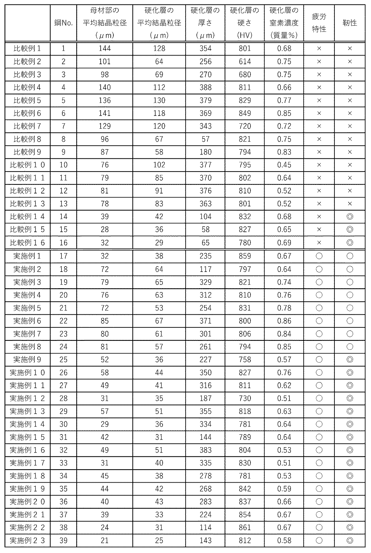
表2に示されるように、実施例1~23は、所定の合金組成及び浸窒指数を満たす鋼板を用いたため、浸窒焼入れ処理後に疲労特性及び靭性が良好であった。
これに対して、比較例1~13は、所定の合金組成を満たしていない鋼板を用いていたため、浸窒焼入れ処理後に疲労特性及び靭性が十分でなかった。
特に、比較例1は、浸窒焼入れ処理時に窒化物を生成する元素を含んでいないため、窒化物の生成による窒素オーステナイトの粗大化抑制の効果が得られず、窒素マルテンサイトの結晶粒も大きくなった。そのため、浸窒焼入れ処理後に疲労特性及び靭性が低下してしまった。
また、比較例2は、Mn及びNiの合計量が少なすぎたため、焼入れ不足が発生し、疲労特性及び靭性が低下した。比較例3も同様に、Mn及びNiの合計量が少なすぎたため、浸窒層のオーステナイト化が不十分であり、オーステナイト結晶粒間に存在するフェライトを十分に低減させることができなかった。そのため、浸窒焼入れ処理後に疲労特性及び靭性が低下した。
これに対して、比較例1~13は、所定の合金組成を満たしていない鋼板を用いていたため、浸窒焼入れ処理後に疲労特性及び靭性が十分でなかった。
特に、比較例1は、浸窒焼入れ処理時に窒化物を生成する元素を含んでいないため、窒化物の生成による窒素オーステナイトの粗大化抑制の効果が得られず、窒素マルテンサイトの結晶粒も大きくなった。そのため、浸窒焼入れ処理後に疲労特性及び靭性が低下してしまった。
また、比較例2は、Mn及びNiの合計量が少なすぎたため、焼入れ不足が発生し、疲労特性及び靭性が低下した。比較例3も同様に、Mn及びNiの合計量が少なすぎたため、浸窒層のオーステナイト化が不十分であり、オーステナイト結晶粒間に存在するフェライトを十分に低減させることができなかった。そのため、浸窒焼入れ処理後に疲労特性及び靭性が低下した。
また、比較例4~7及び10~13は、浸窒焼入れ処理時に窒化物を生成する元素が少なすぎたため、窒化物の生成による窒素オーステナイトの粗大化抑制の効果が得られず、窒素マルテンサイトの結晶粒も大きくなった。そのため、浸窒焼入れ処理後に疲労特性及び靭性が低下してしまった。
また、比較例8及び9は、Si及びAlの量が多すぎたため、窒化物が粗大化してしまい疲労破壊の起点となり易くなった。そのため、浸窒焼入れ処理後に疲労特性及び靭性が低下してしまった。
また、比較例14~16は、浸窒指数が0.7以上であったため、浸窒処理時にオーステナイト成長速度が遅くなり、浸窒層の厚さが小さくなった。そのため、硬化層の厚さも小さくなり、疲労特性及び靭性が低下してしまった。
また、比較例8及び9は、Si及びAlの量が多すぎたため、窒化物が粗大化してしまい疲労破壊の起点となり易くなった。そのため、浸窒焼入れ処理後に疲労特性及び靭性が低下してしまった。
また、比較例14~16は、浸窒指数が0.7以上であったため、浸窒処理時にオーステナイト成長速度が遅くなり、浸窒層の厚さが小さくなった。そのため、硬化層の厚さも小さくなり、疲労特性及び靭性が低下してしまった。
以上の結果からわかるように、本発明によれば、靭性及び疲労強度に優れた浸窒焼入れ部品を製造可能な浸窒焼入れ処理用鋼を提供することができる。また、本発明によれば、靭性及び疲労強度に優れた浸窒焼入れ部品及びその製造方法を提供することができる。
Claims (10)
- C:0.6質量%以下、
Mn及び/又はNi:合計で0.4~3.0質量%、
P:0.03質量%以下、
S:0.03質量%以下、並びに
Cr:0.1~4.5質量%、Si:0.1~1.0質量%及びAl:0.1~1.0質量%から選択される1種以上
を含み、残部がFe及び不可避的不純物からなり、
下記式(1):
A1=0.30Cr+0.45Si+0.34Al-0.2(Mn+Ni) (1)
(式中、各元素記号は、各元素の質量%である)で表される浸窒指数A1が0.7以下である浸窒焼入れ処理用鋼。 - C:0.6質量%以下、
Mn及び/又はNi:合計で0.4~3.0質量%、
P:0.03質量%以下、
S:0.03質量%以下、並びに
V:0.01~1.5質量%、Nb:0.01~3.0質量%及びTi:0.01~1.5質量%から選択される1種以上
を含み、残部がFe及び不可避的不純物からなり、
下記式(2):
A2=0.36V+0.35Nb+0.35Ti-0.20(Mn+Ni) (2)
(式中、各元素記号は、各元素の質量%である)で表される浸窒指数A2が0.7以下である浸窒焼入れ処理用鋼。 - C:0.6質量%以下、
Mn及び/又はNi:合計で0.4~3.0質量%、
P:0.03質量%以下、
S:0.03質量%以下、
Cr:0.1~4.5質量%、Si:0.1~1.0質量%及びAl:0.1~1.0質量%から選択される1種以上、並びに
V:0.01~1.5質量%、Nb:0.01~3.0質量%及びTi:0.01~1.5質量%から選択される1種以上
を含み、残部がFe及び不可避的不純物からなり、
下記式(3):
A3=0.30Cr+0.45Si+0.34Al+0.36V+0.35Nb+0.35Ti-0.20(Mn+Ni) (3)
(式中、各元素記号は、各元素の質量%である)で表される浸窒指数A3が0.7以下である浸窒焼入れ処理用鋼。 - Mo:0.1~2.0質量%及びB:0.0001~0.01質量%から選択される1種以上をさらに含む、請求項1~3のいずれか一項に記載の浸窒焼入れ処理用鋼。
- Cr、Si及びAlの合計量が0.1~4.5質量%である、請求項1、3及び4のいずれか一項に記載の浸窒焼入れ処理用鋼。
- V、Nb及びTiの合計量が0.01~3.0質量%である、請求項2~5のいずれか一項に記載の浸窒焼入れ処理用鋼。
- 請求項1~6のいずれか一項に記載の浸窒焼入れ処理用鋼の表層部に、浸窒焼入れ処理によって窒素マルテンサイトを含む硬化層が形成された浸窒焼入れ部品。
- 前記窒素マルテンサイトの平均結晶粒径が80μm以下である、請求項7に記載の浸窒焼入れ部品。
- 前記硬化層のビッカース硬さが500HV以上である、請求項7又は8に記載の浸窒焼入れ部品。
- 請求項1~6のいずれか一項に記載の浸窒焼入れ処理用鋼を部品形状に加工して浸窒焼入れ処理を行う、浸窒焼入れ部品の製造方法。
Priority Applications (1)
| Application Number | Priority Date | Filing Date | Title |
|---|---|---|---|
| PCT/JP2019/024332 WO2020255303A1 (ja) | 2019-06-19 | 2019-06-19 | 浸窒焼入れ処理用鋼、浸窒焼入れ部品及びその製造方法 |
Applications Claiming Priority (1)
| Application Number | Priority Date | Filing Date | Title |
|---|---|---|---|
| PCT/JP2019/024332 WO2020255303A1 (ja) | 2019-06-19 | 2019-06-19 | 浸窒焼入れ処理用鋼、浸窒焼入れ部品及びその製造方法 |
Publications (1)
| Publication Number | Publication Date |
|---|---|
| WO2020255303A1 true WO2020255303A1 (ja) | 2020-12-24 |
Family
ID=74040347
Family Applications (1)
| Application Number | Title | Priority Date | Filing Date |
|---|---|---|---|
| PCT/JP2019/024332 Ceased WO2020255303A1 (ja) | 2019-06-19 | 2019-06-19 | 浸窒焼入れ処理用鋼、浸窒焼入れ部品及びその製造方法 |
Country Status (1)
| Country | Link |
|---|---|
| WO (1) | WO2020255303A1 (ja) |
Citations (6)
| Publication number | Priority date | Publication date | Assignee | Title |
|---|---|---|---|---|
| JPS5917167B2 (ja) * | 1980-06-09 | 1984-04-19 | 株式会社不二越 | 鋼の焼入方法 |
| JP2012036495A (ja) * | 2010-07-16 | 2012-02-23 | Sumitomo Metal Ind Ltd | 窒化処理機械部品の製造方法 |
| KR20140081124A (ko) * | 2012-12-21 | 2014-07-01 | 주식회사 포스코 | 질화처리용 보론 첨가 고탄소강, 그의 질화처리 방법 및 질화처리된 보론 첨가 고탄소강 |
| JP2018141216A (ja) * | 2017-02-28 | 2018-09-13 | Jfeスチール株式会社 | 部品およびその製造方法 |
| JP2018141218A (ja) * | 2017-02-28 | 2018-09-13 | Jfeスチール株式会社 | 部品およびその製造方法 |
| JP2019049032A (ja) * | 2017-09-11 | 2019-03-28 | 大同特殊鋼株式会社 | 浸窒処理用鋼材 |
-
2019
- 2019-06-19 WO PCT/JP2019/024332 patent/WO2020255303A1/ja not_active Ceased
Patent Citations (6)
| Publication number | Priority date | Publication date | Assignee | Title |
|---|---|---|---|---|
| JPS5917167B2 (ja) * | 1980-06-09 | 1984-04-19 | 株式会社不二越 | 鋼の焼入方法 |
| JP2012036495A (ja) * | 2010-07-16 | 2012-02-23 | Sumitomo Metal Ind Ltd | 窒化処理機械部品の製造方法 |
| KR20140081124A (ko) * | 2012-12-21 | 2014-07-01 | 주식회사 포스코 | 질화처리용 보론 첨가 고탄소강, 그의 질화처리 방법 및 질화처리된 보론 첨가 고탄소강 |
| JP2018141216A (ja) * | 2017-02-28 | 2018-09-13 | Jfeスチール株式会社 | 部品およびその製造方法 |
| JP2018141218A (ja) * | 2017-02-28 | 2018-09-13 | Jfeスチール株式会社 | 部品およびその製造方法 |
| JP2019049032A (ja) * | 2017-09-11 | 2019-03-28 | 大同特殊鋼株式会社 | 浸窒処理用鋼材 |
Similar Documents
| Publication | Publication Date | Title |
|---|---|---|
| JP6089131B2 (ja) | 高炭素冷延鋼板及びその製造方法 | |
| JP5123335B2 (ja) | クランクシャフトおよびその製造方法 | |
| JP5767594B2 (ja) | 窒化用鋼材およびこれを用いた窒化部材 | |
| JP4347763B2 (ja) | 高温浸炭用鋼およびその製造方法 | |
| JP2010189697A (ja) | クランクシャフトおよびその製造方法 | |
| JP4385019B2 (ja) | 鋼製軟窒化機械部品の製造方法 | |
| JP2005097682A (ja) | 無段変速機ベルト用の鋼,鋼板および素材ベルト並びに無段変速機ベルトおよびその製造法 | |
| JP4847681B2 (ja) | Ti含有肌焼き鋼 | |
| JPWO2017056896A1 (ja) | クランク軸粗形材、窒化クランク軸及びその製造方法 | |
| JP2023144640A (ja) | 冷鍛性に優れる窒化用鋼および冷鍛窒化部品 | |
| JP2012077333A (ja) | 被削性に優れた窒化用鋼及び窒化処理部品 | |
| JP7031428B2 (ja) | 浸窒焼入れ処理用鋼、浸窒焼入れ部品及びその製造方法 | |
| JP4946617B2 (ja) | 軟窒化処理用鋼板およびその製造方法 | |
| JP7013833B2 (ja) | 浸炭部品 | |
| JP7168059B2 (ja) | 浸窒焼入れ処理用鋼、浸窒焼入れ部品及びその製造方法 | |
| WO2020255303A1 (ja) | 浸窒焼入れ処理用鋼、浸窒焼入れ部品及びその製造方法 | |
| JP2024114370A (ja) | 冷鍛性と窒化性に優れる窒化用鋼および冷間鍛造窒化部品 | |
| JP2024048190A (ja) | 被削性と窒化特性に優れた窒化用鋼 | |
| JP6300647B2 (ja) | 窒化特性に優れる窒化用鋼 | |
| JP7196707B2 (ja) | 窒化用鍛造部材及びその製造方法、並びに表面硬化鍛造部材及びその製造方法 | |
| JP2023142664A (ja) | 芯部硬さに優れた窒化用鋼 | |
| JP2012001794A (ja) | ベルト式cvtのエレメント用鋼及びこれを用いたエレメント | |
| JP7063070B2 (ja) | 浸炭部品 | |
| JP2020100897A (ja) | 表層硬化用鋼および表層硬化部品 | |
| JP4389726B2 (ja) | 無段変速機ベルトの金属帯リング用薄鋼帯板 |
Legal Events
| Date | Code | Title | Description |
|---|---|---|---|
| 121 | Ep: the epo has been informed by wipo that ep was designated in this application |
Ref document number: 19933376 Country of ref document: EP Kind code of ref document: A1 |
|
| NENP | Non-entry into the national phase |
Ref country code: DE |
|
| 122 | Ep: pct application non-entry in european phase |
Ref document number: 19933376 Country of ref document: EP Kind code of ref document: A1 |
|
| NENP | Non-entry into the national phase |
Ref country code: JP |