WO2020255203A1 - スライドファスナーのファスナーストリンガー、及びスライドファスナー - Google Patents
スライドファスナーのファスナーストリンガー、及びスライドファスナー Download PDFInfo
- Publication number
- WO2020255203A1 WO2020255203A1 PCT/JP2019/023889 JP2019023889W WO2020255203A1 WO 2020255203 A1 WO2020255203 A1 WO 2020255203A1 JP 2019023889 W JP2019023889 W JP 2019023889W WO 2020255203 A1 WO2020255203 A1 WO 2020255203A1
- Authority
- WO
- WIPO (PCT)
- Prior art keywords
- fastener
- braid
- fastener tape
- tape
- width direction
- Prior art date
- Legal status (The legal status is an assumption and is not a legal conclusion. Google has not performed a legal analysis and makes no representation as to the accuracy of the status listed.)
- Ceased
Links
Images


Classifications
-
- A—HUMAN NECESSITIES
- A44—HABERDASHERY; JEWELLERY
- A44B—BUTTONS, PINS, BUCKLES, SLIDE FASTENERS, OR THE LIKE
- A44B19/00—Slide fasteners
- A44B19/24—Details
Definitions
- the present invention relates to a slide fastener in which a pair of fastener stringers can be opened and closed by a slider, and the fastener stringer.
- the above-mentioned fastener tape does not expand or contract so much in the longitudinal direction or the width direction. This is because, for example, in the case of a woven fabric, the warp threads and the weft threads are woven in a state of being alternately orthogonal to each other. Also, in the case of knitting, it is easy to stretch in the direction in which Ranna is straight (weft direction in the case of weft knitting, warp direction in the case of warp knitting), but in the direction of connecting Ranna (warp direction, warp knitting in the case of weft knitting). If so, it is difficult to stretch in the weft direction). Since the fastener tape has such elasticity, the pair of fastener stringers are generally attached to an object such as clothes or a bag in a straight line.
- Patent Document 1 discloses a fastener stringer having a property of being easily curved on a flat surface. This fastener stringer uses a fastener tape woven or a bias tape.
- bias tape exists as a technical term.
- the bias tape is formed by cutting a woven fabric along a direction inclined by about 45 degrees with respect to the warp direction and the weft direction. If the bias tape is in the cut state, it is easy to bend on a flat surface, but the end portion in the width direction is easily frayed. Therefore, when the bias tape is used as a fastener tape, it is necessary to treat both side edges in the width direction so as not to fray, so that the bias tape is difficult to be curved on a flat surface.
- Aya knitting does not exist as a descriptive term, and it is not clear what kind of knitting method it is.
- knitted fabrics are classified into warp knitting and weft knitting as described above from the direction in which the knitting yarn moves. Therefore, Aya knit is a knit that is knitted by either warp or weft. Then, when the woven tape is used as the fastener tape, it becomes difficult to bend it on a flat surface like the bias tape.
- a flat braid is a combination of multiple braids crossed diagonally with respect to the longitudinal direction of the fastener tape.
- the braided material is inclined with respect to the longitudinal direction of the fastener tape, and extends from one end to the other end of the fastener tape while alternately passing through both ends in the width direction of the fastener tape.
- the fastener tape has only a flat braid or not, but it is desirable to do the following to make it easier to fix the element row. That is, the fastener tape is provided with a core material for fixing along one side edge portion in the width direction of the flat braid in addition to the flat braid. The core material is less likely to expand and contract than the flat braid in terms of elasticity of the fastener tape in the longitudinal direction.
- the slide fastener of the present invention includes a pair of the above-mentioned fastener stringers and a slider that can be attached to a pair of element rows and can open and close the pair of fastener stringers.
- fastener stringer and the slide fastener of the present invention use a flat braid for the fastener tape, when curved on a flat surface, one side in the width direction (curved inner side) with respect to the longitudinal dimension of the fastener tape is It becomes shorter and the other side in the width direction becomes longer, which makes it suitable for bending.
- the fastener stringer and the slide fastener of the present invention are provided with a core material
- the side in the width direction of the fastener tape to which the core material is fixed is in the longitudinal direction with respect to the side where the core material is not fixed. Since it is difficult to expand and contract, it is suitable for fixing the element row.
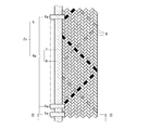
- FIG. 3 is a sectional view taken along line III-III of FIG.
- the slide fastener 1 has a pair of fastener stringers 2 and 2 that form a band and face each other in the width direction of the band, and a pair of fastener stringers 2 and 2 that face each other on their side edges. It is provided with a slider 3 that can be opened and closed in the portion. Since the fastener stringer 2 is strip-shaped, it is elongated, and its long direction is referred to as “longitudinal direction” and its narrow direction (short direction) is referred to as "width direction”.
- the basic state of the fastener stringer 2 is a state in which the fastener stringer 2 is simply placed on a flat surface, that is, a state in which it extends in a straight line.
- the longitudinal direction in the basic state is referred to as the front-rear direction, and the width direction is referred to as the left-right direction.
- the fastener stringer 2 is formed along a strip-shaped fastener tape 4 extending in a straight line in a basic state and one side edge portion in the width direction of the fastener tape 4 (more specifically, one side edge portion on the side of the opposite fastener tape 4). It includes a fixed element row 5.
- the element row 5 is formed by a monofilament composed of elements 6 continuous in the longitudinal direction along the opposite side edges of the fastener tape 4 as shown in FIG. 1, or the fastener tape 4 is opposed to each other as shown in FIG. It is formed by a large number of independent elements 6a arranged in a row at intervals in the longitudinal direction along the side edges.
- the monofilament is, for example, a coiled one.
- the monofilament is fixed to the fastener tape 4 by sewing.
- the independent element 6a is fixed to the fastener tape 4 by a method commonly called crimping.
- the crimping is a method of sandwiching the fastener tape 4 in the thickness direction by utilizing the plastic deformation of the element 6a.
- the slider 3 is attached to a pair of element rows 5 and 5, and can engage and separate the elements 6 and 6a in one element row 5 and the elements 6 and 6a in the other element row 5. Further, the slider 3 is connected to the slider body 3a and the slider body 3a which can engage and separate the pair of element rows 5 and 5 and the pair of fastener tapes 4 and 4 and the opposing elements 6 and 6a. It is provided with a puller 3b for moving 3a.
- the slide fastener 1 of the first embodiment of the present invention has the above-mentioned basic configuration of the slide fastener 1, and also uses the flat braid 7 alone for the fastener tape 4.
- the braid is a combination of a plurality of braided materials 8 diagonally intersecting the longitudinal direction of the fastener tape 4.
- the flat braid 7 is a flat braid, which is flat, more specifically, the width direction is longer than the thickness direction, and both sides in the thickness direction are flat.
- the braid material 8 is not limited to a stretchable material regardless of the material, and may be a non-stretchable material. Further, the braid material 8 is not limited to the thread generally used for the braid, and may be another material such as a wire.
- the braid material 8 is inclined with respect to the longitudinal direction of the fastener tape 4 (flat braid 7) and alternately passes through both ends of the fastener tape 4 in the width direction toward the other end of the fastener tape 4 in the longitudinal direction. It extends.
- the braid material 8 extends in a zigzag manner while being inclined with respect to the longitudinal direction of the fastener tape 4, and both ends of the fastener tape 4 in the width direction are zigzag bending points (folding points). Then, when three bending points arranged in order in the length direction of the braiding material 8 are extracted from any part of the flat braid 7, the shape of the braiding material 8 passing through the three bending points becomes V-shaped. .. That is, in the braid material 8, the V shape is repeated in the longitudinal direction with both ends in the width direction of the flat braid 7 as bending points.
- the braid member 8 when the braid material 8 is directed from one end in the width direction of the flat braid 7 to the other end, the braid member 8 is inclined to one side in the width direction with respect to the longitudinal direction of the flat braid 7 and extends, and the other end in the width direction of the flat braid 7. It slopes to the other in the width direction when going from one end to one end.
- the intersection angle between the straight line and the longitudinal direction of the portion where the braid material 8 is inclined is about 45 degrees.
- all the braid members 8 are inclined to one side in the width direction with respect to the longitudinal direction of the flat braid 7 and the width direction.
- to combine means that the braided members 8 tilted in one direction in the width direction are alternately overlapped on the upper surface and the lower surface in a predetermined number in parallel order with respect to a plurality of braided members 8 tilted in the other direction in the width direction and arranged in parallel.
- one braid member 8 tilting to one side in the width direction is superposed on the upper surface of two braid members 8 leaning to the other in the width direction, and then tilted to the other side in the width direction next to the two.
- the flat braid 7 has an elongated plate shape, and the braid material 8 appears alternately on the upper surface and the lower surface of the flat braid 7, and the braid material 8a tilted to one side in the width direction and the braid material 8b tilted to the other side are vertically overlapped. Therefore, the thickness of the flat braid 7 is about two of the thickness of the braid material 8.
- the braid material 8 is inclined with respect to the longitudinal direction of the fastener tape 4 (flat braid 7), and the upper surface and the lower surface thereof are alternately inclined by the braid material 8 inclined in the opposite direction. Since the braid material 8 is bent (continuously bent) at both ends in the width direction of the fastener tape 4, the pair of fastener stringers 2 and 2 are widened on a flat surface. When curved in the direction, the braid material 8 is deformed corresponding to the curved shape. Bending points of the braid material 8 are arranged at both ends of the fastener tape 4 in the width direction at intervals in the longitudinal direction of the fastener tape 4.
- the distance between the bending points adjacent to each other in the longitudinal direction is larger than that of the curved inner end (the one having the smaller radius of curvature) in both ends in the width direction.
- the curved outer edge (the one with the larger radius of curvature) is longer.
- the width of the curved portion of the fastener tape 4 located outside the curved shape is larger than the width of the fastener tape 4 in the basic state.
- the curved portion of the fastener tape 4 located inside the curved shape becomes narrower and wider than the width of the fastener tape 4 in the basic state.
- the slide fastener 1 of the first embodiment of the present invention described above uses the flat braid 7 for the fastener tape 4, the width of the fastener tape 4 in the longitudinal direction when curved on a plane is obtained.
- One side in the direction (curved inner side) becomes shorter, and the other side in the width direction becomes longer, which is suitable for bending.
- the fastener tape 4 is curved, it is less likely to wavy than a woven fabric or knitted fabric, and can be easily attached to an object.
- the braid material 8 tilted in one direction in the width direction and the braid material 8 tilted in the other direction with respect to the longitudinal direction. Since the sewing thread is sewn to the fastener tape 4 and the object in a form that straddles both sides, the sewing thread of the object is sewn down (commonly known as seam packer) compared to a fabric in which the sewing thread is sewn in a form that straddles only the weft. (It is called a ring.) Is less likely to occur, and wrinkles are less likely to occur on the object.
- the fastener tape 4a is a flat braid 7 and one side edge of the flat braid 7 in the width direction. It includes a core material 9 that is fixed along the portion.
- the core material 9 use a fastener tape 4a that is more difficult to expand and contract in the longitudinal direction than the flat braid 7 (those that do not expand and contract).
- the flat braid 7 expands and contracts in the longitudinal direction of the core member 9.
- the thickness of the fastener tape 4a the portion where the core material 9 and the flat braid 7 overlap is thicker than the portion where only the flat braid 7 is used.
- the core material 9 is fixed to one surface of the flat braid 7 in the thickness direction by welding or sewing.
- the fastener stringer 2 a large number of independent elements 6a are fixed by crimping at intervals along one side edge of the fastener tape 4a. More specifically, the element 6a has a shape that surrounds the overlapping portion of the core material 9 and the flat braid 7 from both sides in the width direction and both sides in the thickness direction, and is adjacent to the core material 9 in the width direction.
- the flat braid 7 is fixed so as to be sandwiched in the thickness direction.
- the fastener tape 4a since the fastener tape 4a includes the core material 9 in addition to the flat braid 7, the side of the width direction of the fastener tape 4a to which the core material 9 is fixed is defined.
- the core member 9 is less likely to expand and contract in the longitudinal direction with respect to the side to which the core material 9 is not fixed, and is suitable for fixing the element row 5 (element 6a).
Landscapes
- Slide Fasteners (AREA)
Abstract
平面上で湾曲させることに適したファスナーテープを有するファスナーストリンガー、およびスライドファスナーを提供することを目的とする。 本発明のスライドファスナー1のファスナーストリンガー2は、ファスナーテープ4,4aと、ファスナーテープの幅方向の一側縁部に沿って固定するエレメント列5とを備えることを前提とする。そしてファスナーテープはエレメント列を固定する平組紐7を用いるものである。平組紐は組紐材が斜めになっており、且つ幅方向の両端部で屈曲しているので、ファスナーテープを平面上で湾曲させやすい。
Description
本発明は、一対のファスナーストリンガーをスライダーによって開閉自在とするスライドファスナー、及びそのファスナーストリンガーに関する。
ファスナーストリンガーはファスナーテープの幅方向の一側縁部に沿ってエレメント列が固定されたものである。そしてファスナーテープには織物や編物が用いられたものが存在する。織物には経糸と緯糸が用いられる。また編物の編み方には緯編と経編とが存在する。そして緯編は、編糸を次々に輪奈(わな)を作りながら緯方向に動かして一列の編地を形成し、その緯方向に編糸を動かす作業を経方向に繰り返して多列の編地を形成しながら、編糸を別の列の輪奈に通して編物を作るようになっている。また経編は、編糸を経方向に動かすこと以外、緯編と同様にして編物を作るようになっている。
上記したファスナーテープは長手方向や幅方向に対してあまり伸縮しない。というのも、例えば織物であれば、経糸と緯糸が交互に直交する状態で織られているからである。また編物であれば、輪奈が真っ直ぐになる方向(緯編ならば緯方向、経編ならば経方向)には伸び易いが、輪奈を連結させる方向(緯編ならば経方向、経編ならば緯方向)には伸び難い。このような伸縮性をファスナーテープが有することから、一対のファスナーストリンガーは一直線になる状態で衣服や鞄等の対象物に取り付けられることが一般的である。
ところでスライドファスナーを取り扱う業界には、ファスナーストリンガーを湾曲させて対象物に取り付けたいという要望が存在する。しかしながら上記したファスナーストリンガーを平面上に置いたまま湾曲させようとすると、長手方向や幅方向にあまり伸縮しないことから、ファスナーテープの幅方向の両端部のうち曲率半径の小さな方の端部では厚み方向に波打つような形状となり、対象物に対して取り付け難くなる。
このような要望に応えるべく、平面上で湾曲させ易い性質のファスナーストリンガーが特許文献1に開示されている。このファスナーストリンガーはファスナーテープにあや編されたものやバイヤステープを用いるものである。
バイヤステープについての詳細な記述は特許文献1にはない。しかしバイヤステープは技術用語として存在する。バイヤステープは、織物を経方向と緯方向に対して約45度傾けた方向に沿って切断して形成されたものである。バイヤステープは切断されたままの状態であれば、平面上で湾曲させ易いが、幅方向の端部がほつれやすい。したがってバイヤステープをファスナーテープとして用いる場合には、幅方向の両側縁部をほつれにくくするように処理しなければならず、そうすると、バイヤステープは平面上で湾曲させ難くなる。
またあや編についての詳細な記述も特許文献1にはない。そしてあや編とは、記述用語として存在しないものと思われ、どのような編み方なのかが定かではない。ちなみに編物は、編糸の動く方向から前述したように経編、緯編に分類される。したがってあや編とは、経編、緯編のいずれかで編まれた編物である。そうすると、あや編されたものをファスナーテープとして用いる場合には、バイヤステープと同様に平面上で湾曲させ難くなる。
本発明は上記実情を考慮して創作されたもので、その目的は平面上で湾曲させることに適したファスナーテープを有するファスナーストリンガー、およびスライドファスナーを提供することである。
本発明のスライドファスナーのファスナーストリンガーは、ファスナーテープと、ファスナーテープの幅方向の一側縁部に沿って固定するエレメント列とを備えることを前提とする。そしてファスナーテープはエレメント列が固定される平組紐を備えるものである。
平組紐は複数の組紐材をファスナーテープの長手方向に対して斜めに交差して組み合わせたものである。そして組紐材はファスナーテープの長手方向に対して傾斜すると共に、ファスナーテープの幅方向の両端を交互に通過しながらファスナーテープの長手方向の一端から他端へ向かって延びるものである。
またファスナーテープは平組紐だけを備えるものなのか、否かを問わないが、エレメント列を固定し易くするには次のようにすることが望ましい。
すなわちファスナーテープは平組紐の他に、平組紐の幅方向の一側縁部に沿って固定する芯材を備えるものである。そしてファスナーテープの長手方向への伸縮性に関して芯材は平組紐よりも伸縮し難いものにする。
すなわちファスナーテープは平組紐の他に、平組紐の幅方向の一側縁部に沿って固定する芯材を備えるものである。そしてファスナーテープの長手方向への伸縮性に関して芯材は平組紐よりも伸縮し難いものにする。
また本発明のスライドファスナーは上記したファスナーストリンガーを一対と、一対のエレメント列に取り付けられると共に一対のファスナーストリンガーを開閉自在なスライダーとを備えるものである。
本発明のファスナーストリンガーおよびスライドファスナーは、ファスナーテープに平組紐を用いているので、平面上で湾曲させた場合に、ファスナーテープの長手方向の寸法に関して幅方向の一方側(湾曲させた内側)が短くなり、幅方向の他方側が長くなり、湾曲に適したものとなる。
また本発明のファスナーストリンガーおよびスライドファスナーは芯材を備えるものであれば、ファスナーテープの幅方向のうち芯材が固定された側に関しては、芯材が固定されていない側に対して長手方向に伸縮し難くなるので、エレメント列を固定するのに適している。
スライドファスナー1は基本的な構成として、図1に示すように、帯状をなすと共に帯状の幅方向に対向する一対のファスナーストリンガー2,2と、一対のファスナーストリンガー2,2をその対向する側縁部において開閉自在なスライダー3とを備えるものである。なおファスナーストリンガー2は帯状なので、細長いものであり、その長い方向を「長手方向」と称し、その細い方向(短い方向)を「幅方向」と称する。
図1の状態とは相違するが、ファスナーストリンガー2は平面上に単に置いた状態、つまり一直線に延びる状態を、基本状態とする。そして基本状態での長手方向を前後方向と称し、幅方向を左右方向と称することにする。
ファスナーストリンガー2は、基本状態において一直線に延びる帯状のファスナーテープ4と、ファスナーテープ4の幅方向の一側縁部(より詳しく言えば対向するファスナーテープ4の側の一側縁部)に沿って固定されたエレメント列5とを備えるものである。
エレメント列5は図1に示すようにファスナーテープ4の対向する側縁部に沿って長手方向に連続するエレメント6からなるモノフィラメントによって形成されたものか、図2に示すようにファスナーテープ4の対向する側縁部に沿って長手方向に間隔をあけて一列に配置された多数の独立したエレメント6aによって形成されたものである。ちなみにモノフィラメントは例えばコイル状に湾曲したものである。そしてモノフィラメントはファスナーテープ4に縫製によって固定される。一方、独立したエレメント6aは俗に加締めと称される手法によってファスナーテープ4に固定される。加締めとは、エレメント6aの塑性変形を利用してファスナーテープ4をその厚み方向に挟む手法である
ファスナーテープ4は帯状である。なおファスナーテープ4の厚み方向のことを上下方向とも称する。
スライダー3は、一対のエレメント列5,5に取り付けられると共に一方のエレメント列5におけるエレメント6,6aと他方のエレメント列5におけるエレメント6,6aとを噛合及び分離可能なものである。またスライダー3は、一対のエレメント列5,5および一対のファスナーテープ4,4を通すと共に対向するエレメント6,6aを噛合および分離可能なスライダー胴体3aと、スライダー胴体3aに連結されると共にスライダー胴体3aを移動させる引手3bとを備える。
本発明の第一実施形態のスライドファスナー1は、スライドファスナー1の上記した基本的な構成を有する他に、ファスナーテープ4に平組紐7を単独で用いたものである。
組紐とは、複数本の組紐材8がファスナーテープ4の長手方向に対して斜めに交差して組み合わされたもののことである。そして平組紐7とは平打ちされた組紐のことで、平らなもの、より詳しく言えば厚み方向の寸法に対して幅方向の寸法が長く、厚み方向の両面が平面状のものである。
組紐材8は材質を問わず、伸縮性のあるものに限らず、伸縮性の無いものであってもよい。また組紐材8は組紐に一般的に用いられる糸に限らず、ワイヤ等の他の材料であっても良い。
組紐材8は、ファスナーテープ4(平組紐7)の長手方向に対して傾斜すると共に、ファスナーテープ4の幅方向の両端を交互に通過しながらファスナーテープ4の長手方向の一端から他端へ向かって延びるものである。言い換えれば、組紐材8は、ファスナーテープ4の長手方向に対して傾斜したままジグザグに延び、且つファスナーテープ4の幅方向の両端をジグザグの屈曲点(折返し点)とするものである。そして平組紐7の任意の部分において、組紐材8の長さ方向において順番に配列された3つの屈曲点を抽出すると、その3つの屈曲点を通過する組紐材8の形は、V形になる。つまり組紐材8は、平組紐7の幅方向の両端を屈曲点とする状態でV形が長手方向に繰り返されるものである。
また組紐材8は、平組紐7の幅方向の一端から他端へ向かうときに、平組紐7の長手方向に対して幅方向の一方に傾斜して延び、平組紐7の幅方向の他端から一端へ向かうときに幅方向の他方に傾斜して延びる。ちなみに本実施形態では組紐材8が傾斜する部分の直線と長手方向との交差角度は約45度であるものとする。また平組紐7の長手方向に関する任意の範囲(例えば図での範囲W)においては、全ての組紐材8は、平組紐7の長手方向に対して幅方向の一方に傾くもの8aと、幅方向の他方に傾くもの8bとに分類される。そして幅方向の片側に傾く組紐材8aと、幅方向の反対側に傾く組紐材8bとが複数本ずつ組み合わさって平組紐7が形成される。
ちなみに組み合わさるとは、幅方向の一方に傾く組紐材8を、幅方向の他方に傾いて且つ並列する複数本の組紐材8に対して並列順に所定本数ずつ上面と下面に交互に重ね合わせるようにして関わらせることである。図1の例では、幅方向の一方に傾く一本の組紐材8は、幅方向の他方に傾く二本の組紐材8の上面に重ね合わせた後に、その隣りにおいて幅方向の他方に傾く二本の組紐材8の下面に重ね合わせることを繰り返して、平組紐7の一部となる。なお平組紐7は細長い板状であり、平組紐7の上面と下面に組紐材8が交互に表れ、幅方向の一方に傾く組紐材8aと他方に傾く組紐材8bとが上下に重なり合っているので、平組紐7の厚みは組紐材8の厚みの約二本分となる。
上記した第一実施形態のスライドファスナー1は、組紐材8がファスナーテープ4(平組紐7)の長手方向に対して傾斜しており、その上面と下面を反対方向に傾斜した組紐材8で交互に押さえる構成になっており、しかも組紐材8がファスナーテープ4の幅方向の両端部で屈曲している(連続して折れ曲がっている)ことから、一対のファスナーストリンガー2,2を平面上で幅方向に湾曲させた場合に、組紐材8が湾曲形状に対応して変形する。なおファスナーテープ4の幅方向の両端にはファスナーテープ4の長手方向に間隔を開けて組紐材8の屈曲点が配置される。そして変形した状態のファスナーテープ4の場合、長手方向に隣り合う屈曲点の間隔は、幅方向の両端のうち湾曲させた内側の端(曲率半径の小さな方)よりも、幅方向の両端のうち湾曲させた外側の端(曲率半径の大きな方)の方が長くなる。また図1に示すようにスライドファスナー1を平面上で幅方向に湾曲させた場合に、湾曲形状の外側に位置するファスナーテープ4の当該湾曲部分の幅は基本状態のファスナーテープ4の幅よりも狭くなり、湾曲形状の内側に位置するファスナーテープ4の当該湾曲部分は基本状態のファスナーテープ4の幅よりも広くなる。ちなみに図1に示す一対のファスナーテープ4,4は基本状態において元々同じ幅のものである。
このように上記した本発明の第一実施形態のスライドファスナー1は、ファスナーテープ4に平組紐7を用いているので、平面上で湾曲させた場合に、ファスナーテープ4の長手方向の寸法に関して幅方向の一方側(湾曲させた内側)が短くなり、幅方向の他方側が長くなり、湾曲に適したものとなる。そしてファスナーテープ4は湾曲させた場合に織物や編物に比べて波打ち難くなり、対象物に取り付け易くなる。
またファスナーテープ4を幅方向のエレメント列5とは反対側において対象物に縫製によって取り付けた場合には、長手方向に対して幅方向の一方に傾く組紐材8と他方に傾く組紐材8との双方に跨る形で縫糸がファスナーテープ4と対象物とに縫い付けられるので、織物のように緯糸にのみ跨る形で縫糸が縫い付けられるものと比べれば、対象物の縫い縮み(俗にシームパッカリングと称される。)が生じ難くなり、対象物にしわが出来難くなる。
また平組紐7を構成する組紐材8は、長手方向に対して傾斜しているので、組紐材8の長手方向がスライダー3の移動方向に対して斜めになり、スライダー3の移動方向に対して織物の緯糸のように直交するものと比べれば、スライダー3の移動に伴う摩擦抵抗が小さくなり、損傷し難くなる。
また本発明の第二実施形態のスライドファスナーに使用するファスナーストリンガー2は、図2,3に示すように、ファスナーテープ4aが平組紐7の他に、平組紐7の前記幅方向の一側縁部に沿って固定する芯材9を備えるものである。
芯材9はファスナーテープ4aの長手方向への伸縮性が平組紐7よりも伸縮し難いもの(伸び縮みしないもの)を用いる。言い換えれば平組紐7は芯材9よりも当該長手方向へ伸縮するものである。また厚みに関してファスナーテープ4aは、芯材9と平組紐7とが重なり合う部分については平組紐7だけの部分よりも厚くなる。ちなみに芯材9は平組紐7の厚み方向の一面に溶着や縫製によって固定される。
また当該ファスナーストリンガー2は、独立した多数のエレメント6aをファスナーテープ4aの一側縁部に沿って間隔を開けて加締めによって固定してある。より詳しく言えば、エレメント6aは、芯材9と平組紐7とが重なり合った部分を幅方向の両側および厚み方向の両側から包囲する形であり、且つ芯材9に対して幅方向の隣りにおいて平組紐7を厚み方向に挟む状態で固定してある。
上記した本発明の第二実施形態のファスナーストリンガー2aはファスナーテープ4aが平組紐7の他に芯材9を備えるので、ファスナーテープ4aの幅方向のうち芯材9が固定された側に関しては、芯材9が固定されていない側に対して長手方向に伸縮し難くなり、エレメント列5(エレメント6a)を固定するのに適している。
本発明は上記実施形態に限定されるものではなく、その趣旨を逸脱しない範囲において適宜変更可能である。例えばスライドファスナーは上記実施形態では平面上において、つまり二次元で湾曲させる状態で使用されるものであったが、本発明ではこれに限らず、三次元で湾曲させる状態で使用されるものであっても良いし、湾曲させずに使用するものであっても良い。また平組紐7は上記実施形態では板状であったが、本発明ではこれに限らず、袋状であっても良い。
1 スライドファスナー
2,2a ファスナーストリンガー
3 スライダー
3a スライダー胴体
3b 引手
4,4a ファスナーテープ
5 エレメント列
6,6a エレメント
7 平組紐
8,8a,8b 組紐材
9 芯材
W 範囲
2,2a ファスナーストリンガー
3 スライダー
3a スライダー胴体
3b 引手
4,4a ファスナーテープ
5 エレメント列
6,6a エレメント
7 平組紐
8,8a,8b 組紐材
9 芯材
W 範囲
Claims (4)
- ファスナーテープ(4,4a)と、前記ファスナーテープ(4,4a)の幅方向の一側縁部に沿って固定するエレメント列(5)とを備え、
前記ファスナーテープ(4,4a)は前記エレメント列(5)が固定される平組紐(7)を備えることを特徴とするスライドファスナー(1)のファスナーストリンガー(2)。 - 前記平組紐(7)は、複数の組紐材(8)を前記ファスナーテープ(4,4a)の長手方向に対して斜めに交差して組み合わせたものであり、
前記組紐材(8)は前記ファスナーテープ(4,4a)の長手方向に対して傾斜すると共に、前記ファスナーテープ(4,4a)の幅方向の両端を交互に通過しながら前記ファスナーテープ(4,4a)の長手方向の一端から他端へ向かって延びるものであることを特徴とする請求項1に記載のスライドファスナー(1)のファスナーストリンガー(2)。 - 前記ファスナーテープ(4,4a)は、前記平組紐(7)の幅方向の前記一側縁部に沿って固定する芯材(9)を備え、
前記ファスナーテープ(4,4a)の長手方向への伸縮性に関して前記芯材(9)は前記平組紐(7)よりも伸縮し難いものであることを特徴とする請求項1又は2に記載のスライドファスナー(1)のファスナーストリンガー(2)。 - 請求項1,2又は3に記載の前記ファスナーストリンガー(2)を一対と、
一対の前記エレメント列(5,5)に取り付けられると共に一対の前記ファスナーストリンガー(2,2)を開閉自在なスライダー(3)とを備えるスライドファスナー(1)。
Priority Applications (2)
| Application Number | Priority Date | Filing Date | Title |
|---|---|---|---|
| PCT/JP2019/023889 WO2020255203A1 (ja) | 2019-06-17 | 2019-06-17 | スライドファスナーのファスナーストリンガー、及びスライドファスナー |
| TW108143037A TW202100057A (zh) | 2019-06-17 | 2019-11-27 | 拉鏈的拉鏈牙鏈帶以及拉鏈 |
Applications Claiming Priority (1)
| Application Number | Priority Date | Filing Date | Title |
|---|---|---|---|
| PCT/JP2019/023889 WO2020255203A1 (ja) | 2019-06-17 | 2019-06-17 | スライドファスナーのファスナーストリンガー、及びスライドファスナー |
Publications (1)
| Publication Number | Publication Date |
|---|---|
| WO2020255203A1 true WO2020255203A1 (ja) | 2020-12-24 |
Family
ID=74040279
Family Applications (1)
| Application Number | Title | Priority Date | Filing Date |
|---|---|---|---|
| PCT/JP2019/023889 Ceased WO2020255203A1 (ja) | 2019-06-17 | 2019-06-17 | スライドファスナーのファスナーストリンガー、及びスライドファスナー |
Country Status (2)
| Country | Link |
|---|---|
| TW (1) | TW202100057A (ja) |
| WO (1) | WO2020255203A1 (ja) |
Citations (3)
| Publication number | Priority date | Publication date | Assignee | Title |
|---|---|---|---|---|
| JPS4839365Y1 (ja) * | 1969-09-11 | 1973-11-20 | ||
| JPS50112305U (ja) * | 1974-02-27 | 1975-09-12 | ||
| JPH0413689U (ja) * | 1990-05-23 | 1992-02-04 |
-
2019
- 2019-06-17 WO PCT/JP2019/023889 patent/WO2020255203A1/ja not_active Ceased
- 2019-11-27 TW TW108143037A patent/TW202100057A/zh unknown
Patent Citations (3)
| Publication number | Priority date | Publication date | Assignee | Title |
|---|---|---|---|---|
| JPS4839365Y1 (ja) * | 1969-09-11 | 1973-11-20 | ||
| JPS50112305U (ja) * | 1974-02-27 | 1975-09-12 | ||
| JPH0413689U (ja) * | 1990-05-23 | 1992-02-04 |
Also Published As
| Publication number | Publication date |
|---|---|
| TW202100057A (zh) | 2021-01-01 |
Similar Documents
| Publication | Publication Date | Title |
|---|---|---|
| JP4076525B2 (ja) | 編成面ファスナー | |
| US3495306A (en) | Variable width seam of interlocking components | |
| TWI382819B (zh) | 彎曲拉鏈 | |
| JP3973483B2 (ja) | 伸縮性経編布地 | |
| CN102713050B (zh) | 用于接合工业用织物两端的铰接式缝合元件 | |
| RU2594850C2 (ru) | Устройство для растягивания стежков, растягивающее устройство для создания сети с растянутыми стежками, способ создания сети с растянутыми стежками и сеть с растянутыми стежками | |
| WO2014119150A1 (ja) | ファスナーテープ無しストリンガー及びスライドファスナー付き物品 | |
| JP5795074B2 (ja) | スライドファスナー及び隠しスライドファスナー | |
| JP2023087074A (ja) | スライドファスナー | |
| TWI574646B (zh) | Chains, zippers and items with zippers | |
| WO2018012008A1 (ja) | 編込みファスナーストリンガー | |
| WO2019106806A1 (ja) | ファスナーテープ、ファスナーストリンガー、スライドファスナー、衣類及び衣類の製造方法 | |
| WO2011007411A1 (ja) | 編込みファスナーストリンガー | |
| NL7905885A (nl) | Ritssluiting. | |
| HK1257304A1 (zh) | 弯曲的滑动紧固件及相关系统 | |
| WO2020255203A1 (ja) | スライドファスナーのファスナーストリンガー、及びスライドファスナー | |
| WO2014002218A1 (ja) | ファスナーストリンガー及びスライドファスナー | |
| JP3406150B2 (ja) | 編込みスライドファスナー | |
| NL8103482A (nl) | Ritssluitingdraagband. | |
| WO2016016952A1 (ja) | ファスナーテープ無しストリンガー、ファスナーテープ無しスライドファスナー、及びスライドファスナー付き物品 | |
| CN87106853A (zh) | 拉链及其制造法 | |
| JP2017018327A (ja) | ファスナーチェーン、及びスライドファスナー | |
| BR112013016718B1 (pt) | fecho deslizante incorporado | |
| US4060886A (en) | Method and apparatus for manufacture of slide fastener stringer | |
| CN109068816B (zh) | 拉链带和拉链带的制造方法 |
Legal Events
| Date | Code | Title | Description |
|---|---|---|---|
| 121 | Ep: the epo has been informed by wipo that ep was designated in this application |
Ref document number: 19933508 Country of ref document: EP Kind code of ref document: A1 |
|
| NENP | Non-entry into the national phase |
Ref country code: DE |
|
| 122 | Ep: pct application non-entry in european phase |
Ref document number: 19933508 Country of ref document: EP Kind code of ref document: A1 |
|
| NENP | Non-entry into the national phase |
Ref country code: JP |