WO2020251041A1 - 回転機器 - Google Patents
回転機器 Download PDFInfo
- Publication number
- WO2020251041A1 WO2020251041A1 PCT/JP2020/023298 JP2020023298W WO2020251041A1 WO 2020251041 A1 WO2020251041 A1 WO 2020251041A1 JP 2020023298 W JP2020023298 W JP 2020023298W WO 2020251041 A1 WO2020251041 A1 WO 2020251041A1
- Authority
- WO
- WIPO (PCT)
- Prior art keywords
- bearing
- shaft member
- rotor
- housing
- rotating device
- Prior art date
- Legal status (The legal status is an assumption and is not a legal conclusion. Google has not performed a legal analysis and makes no representation as to the accuracy of the status listed.)
- Ceased
Links
Images




Classifications
-
- F—MECHANICAL ENGINEERING; LIGHTING; HEATING; WEAPONS; BLASTING
- F04—POSITIVE - DISPLACEMENT MACHINES FOR LIQUIDS; PUMPS FOR LIQUIDS OR ELASTIC FLUIDS
- F04D—NON-POSITIVE-DISPLACEMENT PUMPS
- F04D25/00—Pumping installations or systems
- F04D25/02—Units comprising pumps and their driving means
- F04D25/08—Units comprising pumps and their driving means the working fluid being air, e.g. for ventilation
-
- F—MECHANICAL ENGINEERING; LIGHTING; HEATING; WEAPONS; BLASTING
- F04—POSITIVE - DISPLACEMENT MACHINES FOR LIQUIDS; PUMPS FOR LIQUIDS OR ELASTIC FLUIDS
- F04D—NON-POSITIVE-DISPLACEMENT PUMPS
- F04D19/00—Axial-flow pumps
- F04D19/002—Axial flow fans
-
- F—MECHANICAL ENGINEERING; LIGHTING; HEATING; WEAPONS; BLASTING
- F04—POSITIVE - DISPLACEMENT MACHINES FOR LIQUIDS; PUMPS FOR LIQUIDS OR ELASTIC FLUIDS
- F04D—NON-POSITIVE-DISPLACEMENT PUMPS
- F04D19/00—Axial-flow pumps
- F04D19/007—Axial-flow pumps multistage fans
-
- F—MECHANICAL ENGINEERING; LIGHTING; HEATING; WEAPONS; BLASTING
- F04—POSITIVE - DISPLACEMENT MACHINES FOR LIQUIDS; PUMPS FOR LIQUIDS OR ELASTIC FLUIDS
- F04D—NON-POSITIVE-DISPLACEMENT PUMPS
- F04D29/00—Details, component parts, or accessories
- F04D29/05—Shafts or bearings, or assemblies thereof, specially adapted for elastic fluid pumps
- F04D29/053—Shafts
-
- F—MECHANICAL ENGINEERING; LIGHTING; HEATING; WEAPONS; BLASTING
- F04—POSITIVE - DISPLACEMENT MACHINES FOR LIQUIDS; PUMPS FOR LIQUIDS OR ELASTIC FLUIDS
- F04D—NON-POSITIVE-DISPLACEMENT PUMPS
- F04D29/00—Details, component parts, or accessories
- F04D29/05—Shafts or bearings, or assemblies thereof, specially adapted for elastic fluid pumps
- F04D29/056—Bearings
-
- F—MECHANICAL ENGINEERING; LIGHTING; HEATING; WEAPONS; BLASTING
- F04—POSITIVE - DISPLACEMENT MACHINES FOR LIQUIDS; PUMPS FOR LIQUIDS OR ELASTIC FLUIDS
- F04D—NON-POSITIVE-DISPLACEMENT PUMPS
- F04D29/00—Details, component parts, or accessories
- F04D29/05—Shafts or bearings, or assemblies thereof, specially adapted for elastic fluid pumps
- F04D29/056—Bearings
- F04D29/059—Roller bearings
-
- F—MECHANICAL ENGINEERING; LIGHTING; HEATING; WEAPONS; BLASTING
- F04—POSITIVE - DISPLACEMENT MACHINES FOR LIQUIDS; PUMPS FOR LIQUIDS OR ELASTIC FLUIDS
- F04D—NON-POSITIVE-DISPLACEMENT PUMPS
- F04D29/00—Details, component parts, or accessories
- F04D29/26—Rotors specially for elastic fluids
- F04D29/32—Rotors specially for elastic fluids for axial flow pumps
- F04D29/325—Rotors specially for elastic fluids for axial flow pumps for axial flow fans
-
- F—MECHANICAL ENGINEERING; LIGHTING; HEATING; WEAPONS; BLASTING
- F04—POSITIVE - DISPLACEMENT MACHINES FOR LIQUIDS; PUMPS FOR LIQUIDS OR ELASTIC FLUIDS
- F04D—NON-POSITIVE-DISPLACEMENT PUMPS
- F04D29/00—Details, component parts, or accessories
- F04D29/26—Rotors specially for elastic fluids
- F04D29/32—Rotors specially for elastic fluids for axial flow pumps
- F04D29/38—Blades
-
- F—MECHANICAL ENGINEERING; LIGHTING; HEATING; WEAPONS; BLASTING
- F04—POSITIVE - DISPLACEMENT MACHINES FOR LIQUIDS; PUMPS FOR LIQUIDS OR ELASTIC FLUIDS
- F04D—NON-POSITIVE-DISPLACEMENT PUMPS
- F04D29/00—Details, component parts, or accessories
- F04D29/40—Casings; Connections of working fluid
- F04D29/52—Casings; Connections of working fluid for axial pumps
- F04D29/54—Fluid-guiding means, e.g. diffusers
- F04D29/541—Specially adapted for elastic fluid pumps
- F04D29/542—Bladed diffusers
-
- F—MECHANICAL ENGINEERING; LIGHTING; HEATING; WEAPONS; BLASTING
- F04—POSITIVE - DISPLACEMENT MACHINES FOR LIQUIDS; PUMPS FOR LIQUIDS OR ELASTIC FLUIDS
- F04D—NON-POSITIVE-DISPLACEMENT PUMPS
- F04D29/00—Details, component parts, or accessories
- F04D29/40—Casings; Connections of working fluid
- F04D29/52—Casings; Connections of working fluid for axial pumps
- F04D29/54—Fluid-guiding means, e.g. diffusers
- F04D29/541—Specially adapted for elastic fluid pumps
- F04D29/542—Bladed diffusers
- F04D29/544—Blade shapes
-
- F—MECHANICAL ENGINEERING; LIGHTING; HEATING; WEAPONS; BLASTING
- F04—POSITIVE - DISPLACEMENT MACHINES FOR LIQUIDS; PUMPS FOR LIQUIDS OR ELASTIC FLUIDS
- F04D—NON-POSITIVE-DISPLACEMENT PUMPS
- F04D29/00—Details, component parts, or accessories
- F04D29/58—Cooling; Heating; Diminishing heat transfer
- F04D29/5806—Cooling the drive system
-
- H—ELECTRICITY
- H02—GENERATION; CONVERSION OR DISTRIBUTION OF ELECTRIC POWER
- H02K—DYNAMO-ELECTRIC MACHINES
- H02K1/00—Details of the magnetic circuit
- H02K1/06—Details of the magnetic circuit characterised by the shape, form or construction
- H02K1/22—Rotating parts of the magnetic circuit
- H02K1/27—Rotor cores with permanent magnets
- H02K1/2786—Outer rotors
- H02K1/2787—Outer rotors the magnetisation axis of the magnets being perpendicular to the rotor axis
- H02K1/2789—Outer rotors the magnetisation axis of the magnets being perpendicular to the rotor axis the rotor consisting of two or more circumferentially positioned magnets
- H02K1/2791—Surface mounted magnets; Inset magnets
-
- H—ELECTRICITY
- H02—GENERATION; CONVERSION OR DISTRIBUTION OF ELECTRIC POWER
- H02K—DYNAMO-ELECTRIC MACHINES
- H02K5/00—Casings; Enclosures; Supports
- H02K5/04—Casings or enclosures characterised by the shape, form or construction thereof
- H02K5/16—Means for supporting bearings, e.g. insulating supports or means for fitting bearings in the bearing-shields
- H02K5/173—Means for supporting bearings, e.g. insulating supports or means for fitting bearings in the bearing-shields using bearings with rolling contact, e.g. ball bearings
- H02K5/1737—Means for supporting bearings, e.g. insulating supports or means for fitting bearings in the bearing-shields using bearings with rolling contact, e.g. ball bearings radially supporting the rotor around a fixed spindle; radially supporting the rotor directly
-
- H—ELECTRICITY
- H02—GENERATION; CONVERSION OR DISTRIBUTION OF ELECTRIC POWER
- H02K—DYNAMO-ELECTRIC MACHINES
- H02K7/00—Arrangements for handling mechanical energy structurally associated with dynamo-electric machines, e.g. structural association with mechanical driving motors or auxiliary dynamo-electric machines
- H02K7/14—Structural association with mechanical loads, e.g. with hand-held machine tools or fans
-
- H—ELECTRICITY
- H02—GENERATION; CONVERSION OR DISTRIBUTION OF ELECTRIC POWER
- H02K—DYNAMO-ELECTRIC MACHINES
- H02K9/00—Arrangements for cooling or ventilating
- H02K9/02—Arrangements for cooling or ventilating by ambient air flowing through the machine
- H02K9/04—Arrangements for cooling or ventilating by ambient air flowing through the machine having means for generating a flow of cooling medium
- H02K9/06—Arrangements for cooling or ventilating by ambient air flowing through the machine having means for generating a flow of cooling medium with fans or impellers driven by the machine shaft
Definitions
- the present invention relates to a rotating device, and more particularly to a rotating device that generates wind for the purpose of intake or ventilation.
- an example of the present invention is to provide a rotating device that can meet the demand for miniaturization.
- Another object of the present invention is to provide a rotating device having excellent basic performance in generating wind while fulfilling the demand for miniaturization.
- the rotating device of the present invention Shaft member and A tubular rotating body that can rotate with respect to the shaft member, A tubular housing surrounding the rotating body and A bearing that supports the rotating body with respect to the shaft member, With the stator inside the rotating body, With one or more rotor blades provided on the rotating body, To be equipped.
- the rotating device of the present invention at least one end of the shaft member or its vicinity may be fixed to the housing.
- a stationary blade may be provided on the inner surface of the housing facing the outer surface of the rotating body.
- the moving blade and the stationary blade are arranged side by side at a predetermined interval in the axial direction of the shaft member.
- the rotating device of the present invention includes two bearings, a first bearing and a second bearing.
- the first bearing is arranged on one end side of the two ends of the shaft member.
- the second bearing may be arranged on the other end side of the shaft member.
- the position of the moving blade and the position of the first bearing overlap at least partly, and the position of the stationary blade and the position of the second bearing are aligned. It is preferable that at least a part of them overlap.
- the one or a plurality of moving blades are arranged between the first shaft member and the second shaft member in the axial direction of the shaft member.
- a preload in the direction of the other bearing may act on the inner peripheral ring fixed to the shaft member in either the first bearing or the second bearing. ..
- the moving blade may be arranged at the center of the rotating body in the axial direction of the shaft member. Further, in the rotating device of the present invention, the moving blade includes a tubular portion and a plurality of blades provided on the tubular portion. The plurality of blades may be provided on the tubular portion at predetermined intervals in the circumferential direction of the tubular portion.
- FIG. 5 is a cross-sectional view taken out from the rotating device according to the sixth embodiment, which is an example of the present invention, with the inner housing taken out together with a stationary blade provided on the inner circumference thereof, and cut out in a cross section including the axis x.
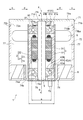
- FIG. 1 is a cross-sectional view of a rotating device 1 according to a first embodiment, which is an example of the present invention.
- the terms upward and downward mean the vertical relationship in FIG. 1, and do not necessarily coincide with the vertical relationship in the direction of gravity.
- the arrow a direction is defined as the upper side a
- the arrow b direction is defined as the lower side b.
- the direction perpendicular to the axis x hereinafter, also referred to as “diameter direction”
- the direction away from the axis x (arrow c direction) is the outer peripheral side c
- the direction toward the axis x (arrow d direction) is the inner circumference. Let it be the side d.
- the clockwise direction in the circumferential direction (circumferential direction seen from the upper side a) about the rotation axis x is the circumferential direction e
- the counterclockwise direction is the circumferential direction f.
- the circumferential direction e and the circumferential direction f are not shown in FIG.
- the portion that rotates in the rotating device 1 is referred to as a "rotating side", and the portion that supports the member on the rotating side and is fixed without rotating itself is referred to as a "fixed side".
- a rotating side the portion that supports the member on the rotating side and is fixed without rotating itself
- a fixed side Each may be referred to.
- the portion that is fixed without rotating by itself since the portion that is fixed without rotating by itself is stationary relative to the rotating portion, the portion that is fixed without rotating by itself may be referred to as a stationary portion.
- the expression representing the part such as " is the same in all subsequent embodiments.
- the rotating device 1 of the present embodiment has a shaft member 5, a rotor 3 which is a cylindrical rotating body rotatable with respect to the shaft member 5, a tubular housing 7 surrounding the rotor 3, and a rotor 3 as a shaft.
- a bearing 4 that supports the member 5, a stator 2 inside the rotor 3, a plurality of moving blades 6 provided on the rotor 3, and an inner surface of the housing 7 facing the outer surface of the rotor 3 are provided. It is equipped with a stationary wing 8.
- the stator 2 includes a stator core 21 which is fixed to the shaft member 5 and has a magnetic pole portion 23 which is fixed to the shaft member 5 and extends radially on the outer peripheral side c about the shaft member 5, and a coil 22 wound around the magnetic pole portion 23.
- the illustrated stator 2 is arranged in the housing 7 so that the gap between the second bearing 42 and the stator 2 is larger than the gap between the first bearing 41 and the stator 2.
- the stator core 21 is a laminated body in which magnetic materials such as silicon steel plates are stacked, and the annular portion 24 coaxially arranged so as to surround the shaft member 5 and the annular portion 24 to the outer peripheral side c. It is composed of a plurality of magnetic pole portions 23 formed so as to extend radially in the radial direction.
- the coil 22 is wound around each of the plurality of magnetic pole portions 23 in the stator core 21.
- the stator core 21 and the coil 22 are insulated by an insulator (not shown) formed of an insulator. Instead of the insulator, the surface of the stator core 21 may be coated with an insulating film to insulate the coil.
- the rotor 3 includes a magnet 31 that faces the magnetic pole portion 23 on the outer peripheral side c of the stator 2, and a tubular tubular member 32 in which the magnet 31 is arranged on the inner peripheral surface.
- the tubular member 32 has a cylindrical shape centered on the shaft of the shaft member 5, and is in a state of surrounding the stator 2.
- the tubular member 32 also has a function of preventing leakage of a magnetic field from the inside of the tubular member 32, and is formed of a magnetic material.
- the tubular member 32 may be made of a non-magnetic material such as aluminum or plastic as long as there is no problem in characteristics.
- the magnet 31 is attached to the inner peripheral surface of the tubular member 32 so as to face the stator 2.
- the magnet 31 has an annular shape, and a region magnetized on the N pole and a region magnetized on the S pole are alternately provided along the circumferential direction at regular intervals (or at regular intervals). Has been done.
- the magnet 31 may be an annular integrally molded product, but a plurality of magnets may be arranged side by side on the inner peripheral surface of the tubular member 32 and arranged in a tubular shape.
- the bearing 4 is arranged on both sides of the stator 2 in the axial direction of the shaft member 5, and has two bearings, a first bearing 41 located on the upper side a and a second bearing 42 located on the lower side b. That is, the magnet 31 and the stator 2 are located between the first bearing 41 and the second bearing 42 in the axial direction of the shaft member 5.
- the first bearing 41 and the second bearing 42 use members having the same configuration (same shape, structure, size, and material). Hereinafter, the first bearing 41 will be described, but the same applies to the second bearing 42.
- the first bearing 41 is a so-called ball bearing including an outer peripheral ring 41a, an inner peripheral ring 41b, and a bearing ball 41c interposed between the outer peripheral ring 41a and the inner peripheral ring 41b. Since the bearing ball 41c rolls between the outer peripheral ring 41a and the inner peripheral ring 41b, the rotational resistance of the inner peripheral ring 41b with respect to the outer peripheral ring 41a is significantly reduced. Due to its function, the first bearing 41 is made of, for example, a hard metal such as iron or a member such as ceramics.
- the inner peripheral ring 41b of the first bearing 41 is gap-fitted to the shaft member 5 and then fixed with an adhesive. Therefore, the gap between the inner peripheral ring 41b of the first bearing 41 and the shaft member 5 is filled with an adhesive, and the inner peripheral ring 41b of the first bearing 41 is fixed to the shaft member 5 together with the shaft member 5. It becomes a stationary part. Further, the inner peripheral ring 42b of the second bearing is fixed to the shaft member 5 by press fitting, and becomes a stationary portion together with the shaft member 5.
- the shaft member 5 and the housing 7 are members that are (relatively) stationary with respect to the rotor 3. Therefore, these are collectively referred to as a stationary member (resting portion).
- the outer peripheral ring 41a of the first bearing 41 and the outer peripheral ring 42a of the second bearing 42 are fixed to the inner peripheral surfaces of both ends of the tubular member 32.
- the inner peripheral ring 41b of the first bearing 41 and the inner peripheral ring 42b of the second bearing 42 are fixed to the outer peripheral surface of the shaft member 5.
- the rotor 3 is configured to be rotatable around the axis x of the shaft member 5.
- the radial dimension t which is the radial dimension of the bearing 4 (first bearing 41)
- the radial dimension s which is the radial dimension of the stator 2. (T> s).
- the shaft member 5 is made of, for example, aluminum for weight reduction, and is in a hollow state (more specifically, a cylindrical state).
- the shaft member 5 is a member on the fixed side. Since the member has a function of supporting the stator 2, the rotor 3, the bearing 4, and the moving blade 6 with respect to the housing 7, rigidity corresponding to the function is required.
- An opening (not shown) is provided in the middle (intermediate portion) of the shaft member 5, and a lead wire (not shown) connected to the coil 22 is drawn into the cavity inside the shaft member 5 from the opening.
- the shaft member 5 is pulled out of the rotating device 1 through an end opening (not shown).
- both ends of the tubular member 32 are closed by the first bearing 41 and the second bearing 42. Power must be supplied to the coil 22 of the stator 2 in this closed space.
- the inside of the space closed by the tubular member 32 and the bearing 4 and the outside thereof are electrically connected by passing a lead wire through the cavity inside the shaft member 5. Therefore, the lead wire can supply power to the coil 22 of the stator 2 in the closed space.
- the motor portion (the portion composed of the stator 2, the rotor 3, the bearing 4 and the shaft member 5; the same shall apply hereinafter) in the rotating device 1 configured as described above is attached to the stator 2 fixed to the shaft member 5.
- the rotor 3 surrounding the stator 2 is rotatable, and constitutes a so-called outer rotor type brushless motor.
- a shaft member fixed to the rotor rotates and a rotational force is extracted by the shaft member.
- the shaft member 5 is used. Is a member on the fixed side, and is configured so that the rotational force is directly extracted from the rotor 3.
- the housing 7 is a member having a cylindrical shape, and is made of, for example, plastic or metal. Although not shown, both ends of the housing 7 in the axial direction are openings (hereinafter, the opening on the upper side a is referred to as an "upper end opening” and the opening on the lower side b is referred to as a "lower end opening”). ing. A space 77 communicating from the upper end opening to the lower end opening is formed as a ventilation path between the inner peripheral surface of the housing 7 and the outer peripheral surface of the tubular member 32.
- the outer peripheral surface of the tubular member 32 of the rotor 3 protrudes toward the inner peripheral surface of the housing 7 (to the outer peripheral side c) in a region overlapping the first bearing 41 in the axial direction (axis x direction) of the shaft member 5.
- the moving blade 6 is attached.
- the moving blade 6 includes a plurality of blades arranged at predetermined intervals in the circumferential direction of the outer peripheral surface of the tubular member 32, and is adapted to rotate with the rotation of the rotor 3, and the rotation direction of the moving blade 6 is increased by the rotation of the moving blade 6. In response to this, air is generated in the space 77 in either the vertical direction or the vertical direction.
- the rotating device 1 is driven to rotate the moving blade 6 in the clockwise direction e, so that the air taken in from the upper end opening is blown out from the lower end opening. Has been done.
- the position of the rotor blade 6 in the rotor 3 in the axis x direction is biased to the upper side a. Since the moving blade 6 is close to the upper end opening on the side where air is taken in, the rotating device 1 of the present embodiment has high air suction efficiency. On the other hand, since the position of the rotor blade 6 in the axis x direction is biased to the upper side a, the position of the center of gravity of the rotor 3 is also biased to the upper side a in order to be biased to the upper side a in accordance with this. There is.
- the magnet 31 is arranged at a position in the x-direction of the axis so that the distance between the magnet 31 and the first bearing 41 is closer than that between the magnet 31 and the second bearing 42.
- the position of the magnet 31 in the axis x direction closer to the position of the rotor blade 6 in the axis x direction, the position of the center of gravity of the rotor 3 and the position of the rotor blade 6 in the axis x direction are closer to each other, so that the rotation of the rotor 3 can be easily stabilized. .. Stabilization of the rotation of the rotor 3 is expected to bring about a high-speed rotation of the rotor 3 and an increase in the amount of air blown as the rotating device 1.
- the housing 7 has a tubular main body (hereinafter, referred to as “housing main body”) 78 having a bottom portion in which a motor portion and a moving blade 6 are housed, and a lid body that covers an upper opening of the housing main body 78. 71 and.
- the lid body 71 includes a flat cylindrical tubular portion (hereinafter referred to as a “lid tubular portion”) 71b and a plurality (for example, four) of the lid tubular portion 71b extending from the upper end to the inner peripheral side d. It includes a spoke portion (hereinafter, referred to as a “lid spoke portion”) 71a and a disk portion (plate portion) 71c to which the lid spoke portion 71a is connected. Regions other than the lid spoke portion 71a and the disk portion 71c at the upper end of the lid body 71 form the upper end opening.
- the housing main body 78 is a donut-shaped support portion (hereinafter, downward support portion) connected to a cylindrical tubular portion (hereinafter, referred to as “housing tubular portion”) 72 and an inner peripheral portion of the stationary blade 8. Included) 74 and. A region other than the lower support portion 74 at the lower end of the housing main body 78 constitutes the lower end opening.
- the lower support portion 74 includes an annular bottom surface portion 74b, a tubular portion (hereinafter, referred to as “outer tubular portion”) 74a that rises from the outer peripheral end of the outer peripheral side c of the bottom surface portion 74b to the upper side a, and a bottom surface portion. Includes a tubular portion (hereinafter, referred to as “inner tubular portion”) 74c that slightly rises from the inner peripheral end of the inner peripheral side d of the 74b to the upper side a.
- the annular bottom surface portion 74b is a connecting portion that connects the inner tubular portion 74c to the inner peripheral portion of the stationary blade 8.
- the inner diameter of the inner tubular portion 74c is substantially the same as the end portion of the shaft member 5, or slightly smaller than the end portion of the shaft member 5, so that the end portion of the shaft member 5 is press-fitted. ing. Further, the upper end of the inner tubular portion 74c is in contact with the inner peripheral ring 42b of the second bearing 42, and is positioned by pressing the inner peripheral ring 42b of the second bearing 42.
- a stage 75 that supports the housing 7 is joined to the lower b-side surface of the bottom surface portion 74b via a joining plate 76 as another member.
- the stage 75 has an annular shape when viewed from below, and functions as a connecting member or a support base (foot) when the rotating device 1 is supported or placed on another member.
- the outer tubular portion 74a faces the inner peripheral surface of the housing tubular portion 72 while maintaining a certain interval.
- a stationary blade 8 is arranged between the outer tubular portion 74a and the housing tubular portion 72. The position where the stationary blade 8 is arranged is a region that overlaps with the second bearing 42 in the axial direction (axis x direction) of the shaft member 5.
- the stationary blade 8 is a member having a function of rectifying the downward wind flow generated by the moving blade 6.
- the shape of the stationary blade 8 is a plate-like shape that partitions a plurality of flow paths parallel to the axial direction of the shaft member 5, and specifically, for example, a cylindrical shape having a different diameter centered on the axis x.
- the shape of the hole seen from above or below may be a grid shape, a honeycomb shape, a shape in which circles are laid out, a shape in which triangles are laid out, a shape in which other polygons are laid out, or the like. .. Further, if necessary, the direction of the flow path may be oblique to the axial direction of the shaft member 5.
- the moving blades 6 and the stationary blades 8 are arranged side by side at predetermined intervals in the axial direction (axis x direction) of the shaft member 5.
- the air flow is effectively rectified. Therefore, a larger amount of air can be discharged from the lower end opening with a high wind pressure.
- the rectifying effect is not sufficient if it is too close, and the wind pressure drops if it is too far, which is not preferable.
- the preferable value of the "predetermined interval” varies depending on various conditions such as the diameters of the moving blades 6 and the stationary blades 8, the distance between the housing 7 and the rotor 3, the rotation speed of the moving blades 6, etc. It is preferable to select from a length L or more from the base of 6 (the outer peripheral surface of the tubular member 32) to the tip (the end of the outer peripheral side c) and 5 times (5 L) or less of the length L. It is more preferable to select from the range of 4 L or less.
- a ring-shaped rib 71d that fits with the end of the shaft member 5 is formed on the lower b-side portion of the disk portion 71c of the lid body 71.
- the end portion of the shaft member 5 can be positioned.
- the shaft member 5 is passed through the hole of the donut-shaped fixing member 92 so that the fixing member 92 covers the lower b side of the disk portion 71c in the lid 71 and the rib 71d is covered with the fixing member 92. By fixing, the end portion of the shaft member 5 can be positioned.
- a disc spring 91 which is an elastic member, is interposed between the lower surface of the fixing member 92 and the upper surface of the inner peripheral ring 41b of the first bearing 41.
- the inner peripheral ring 41b of the first bearing 41 is fixed to the shaft member 5 with an adhesive or the like while the inner peripheral ring 41b included in the first bearing 41 gap-fitted in the shaft member 5 is positioned. be able to.
- a protruding portion 71ba protruding toward the lower side b on the outer peripheral side c, and a notch portion cut out from the end portion of the lower side b toward the upper side a on the inner peripheral side d.
- 71bb is formed.
- a protrusion 72a protruding toward the upper side a on the inner peripheral side d and a notch cut out from the end portion of the upper side a toward the lower side b on the outer peripheral side c. Part 72b is formed.
- the lid tubular portion 71b of the lid body 71 and the housing tubular portion 72 of the housing main body 78 form a recess (hereinafter, referred to as a protrusion) 71ba of the lid tubular portion 71b as a recess of the housing tubular portion 72. It is connected to 72b (hereinafter referred to as a notch portion) and by engaging the protrusion 72a of the housing tubular portion 72 with the notch 71bb of the lid tubular portion 71b.
- the housing 7 is a separate body of the housing main body 78 and the lid 71, and the lid 71 can be removed from and attached to the housing main body 78.
- the rotating device 1 of the present embodiment is manufactured by temporarily fixing the motor portion to which the moving blade 6 is attached to the inside of the housing main body 78 with the lid 71 removed, and then attaching the lid 71. Can be done. Temporary fastening of the motor portion to the housing main body portion 78 is performed by press-fitting the end portion of the shaft member 5 into the inner tubular portion 74c.
- any of conventionally known methods such as fitting, screwing, locking, screwing, clipping, tape sticking, adhesion and welding, etc. It may be. However, if the lid 71 is attached to the housing main body 78 and then can be removed again, the rotating device 1 can be repaired or replaced in the event of a failure or the like. From that point of view, fitting, screwing, locking, screwing, clipping or taped is preferred.
- the rotating device 1 has a configuration in which the shaft member 5 is on the fixed side and the rotor 3 which is a rotating body is rotated with respect to the shaft member 5 via the bearing 4, and thus is shown in FIG.
- the radial dimension s of the stator 2 can be made smaller (t> s) than the radial dimension t of the bearing 4. Therefore, the stator 2 can be made very small.
- stator and the shaft member on the fixed side located inside the rotating body are used. Since the bearing must be arranged between the bearings, the radial dimension a of the stator is inevitably larger (t ⁇ s) than the radial dimension b of the bearing 4.
- the rotating device 1 has a structure in which moving blades 6 are provided on the outer peripheral surface of a rotor 3 which is a rotating body, and a tubular housing 7 is provided so as to surround the moving blades 6, thereby opening both ends of the housing 7.
- One of the portions is an intake port and the other is a discharge port, and the motor portion and the moving blade 6 can be housed in the internal space of the housing 7.
- the moving blade 6 is located in the flow path through which air flows (sometimes referred to as an air passage), space can be saved and the entire rotating device can be miniaturized.
- the space 77 communicating from the upper end opening to the lower end opening is hollow so as not to obstruct the air flow by members other than the lid spoke portion 71a and the stationary blade 8. ing. Further, since the space 77 is a straight tube except for the space occupied by the cylindrical motor, air can flow straight. Therefore, by rotating the moving blade 6, air can be sent straight from the upper end opening toward the lower end opening. Therefore, according to the rotating device 1 according to the present embodiment, air can be efficiently sent out, and strong wind and large air volume can be supplied.
- the stationary blade 8 when an attempt is made to provide a stationary blade 8 for rectification in the frame tubular portion 72 located downstream of the moving blade 6 (bearing 42 side), the stationary blade 8 is also placed in the internal space of the housing 7 as it is. It can be stored, space can be saved, and the size increase of rotating equipment can be suppressed. At this time, in order to further rectify the air by the stationary blade 8, it is desired that the moving blade 6 and the stationary blade 8 are separated to some extent (at a predetermined interval). According to the configuration of the present embodiment, the moving blades 6 and the stationary blades 8 can be arranged in the axial direction of the shaft member 5 inside the housing 7, and the distance between them can be easily adjusted appropriately. Therefore, according to the present embodiment, it is possible to design the air rectification efficiency to be high.
- the position of the moving blade 6 and the position of the first bearing 41 partially overlap, and the position of the stationary blade 8 and the second bearing 42 Partially overlaps with the position of.
- the position of the moving blade 6 at a position that at least partially overlaps the position of the first bearing 41, the moving blade 6 can be brought closer to the upper end opening on the air intake side to improve the air suction efficiency and the second.
- the stationary blade 8 at a position where it overlaps with the position of the bearing 42 at least in part, the distance between the moving blade 6 and the stationary blade 8 can be secured, and the rectification efficiency by the stationary blade can be secured despite its small size. Can be raised.
- a rotating device having a conventional motor configuration in which a rotating shaft member protrudes from the motor, one side of the shaft member is supported and rotated, and a rotational force is extracted from the protruding other side.
- the rotor 3 itself supported by the bearing 4 rotates as a rotating body, so that the rotation of the rotor 3 is stable.
- the shaft member 5 is used.
- the rotation of the rotor 3 is stable.
- the first bearing 41 and the second bearing 42 which are constituent members of the rotor 3 which is a rotating body and have a predetermined weight, rotatably support the rotor 3 in the axial direction of the shaft member 5. Since it is between them, the balance in the axial direction is improved and the rotation of the rotor 3 is stabilized.
- the bearings are arranged at both ends of the rotating body as in the present embodiment, but if the bearings are located near both ends of the rotating body, the rotating body can sufficiently rotate with respect to the shaft member. It will be in a stable state.
- the "neighborhood" referred to here may be a position near both ends of the rotating body and cannot be clearly defined numerically. For example, a region having a length of 20% from both ends in the axial direction of the rotating body. A region, preferably 10% in length from both ends, is included in the concept of "near both ends".
- the rotating device 1 since the first bearing 41 and the second bearing 42 have the same configuration, the outer ring 41a, 42a and the rotor 3 which are a part of the bearing 4 are included. Since the axial balance of the rotating portion is improved and the axial balance of the rotating device 1 as a whole is improved, the rotation of the rotor 3 is stabilized from this viewpoint as well.
- the rotating device 1 according to the present embodiment can realize the miniaturization of the entire device, is less likely to cause fluctuations in the rotation of the rotor 3, and can achieve high-precision stabilization. Further, stabilizing the rotation of the rotor 3 means that uneven rotation is less likely to occur, so that the torque of the rotating device 1 can be increased. That is, the rotating device 1 according to the present embodiment can be provided with excellent characteristics as a rotating device while realizing miniaturization.
- the upper and lower ends of the shaft member 5 are fixed to the housing 7 as an example, but the fixed side shaft member 5 is fixed to the housing 7 in some way. It suffices if at least one end or the vicinity thereof is fixed to the housing.
- the fixing member 92 is fixed to the lower b side portion of the annular portion 71c, and the disc spring 91 is further fixed in a state of being pressed from above by the fixing member 92. , Not limited to this configuration. If necessary, it is not necessary to provide both or one of the fixing member 92 and the disc spring 91.
- a spacer is provided between the second bearing 42 and the magnet 31 in the axial direction of the shaft member 5, and the spacer is used to provide a second spacer on the inner surface of the tubular member 32 in the axial direction of the shaft member 5.
- the bearing 42 may be positioned. In this case, of the ends of the magnet 31 on the second bearing 42 side, a portion closer to the stator 2 may be arranged so as to project toward the second bearing 42 to support the spacer. Further, if necessary, it is not necessary to provide a spacer between the second bearing 42 and the magnet 31 in the axial direction of the shaft member 5.
- the rotating device 1 is provided with the housing 7, but the housing 7 may not be provided if necessary. Therefore, the rotating device 1 in the present application includes a configuration in which the housing 7 is provided or the housing 7 is not provided. Further, in the present application, a shaft member, a tubular rotating body that can rotate with respect to the shaft member, a bearing that supports the rotating body with respect to the shaft member, and a stator inside the rotating body. , A rotating device including one or more moving blades provided on the rotating body is disclosed. Further, according to this rotating device, miniaturization can be achieved.
- this rotating device includes a magnet attached to the inner surface of the tubular member, and the end of the magnet on the first bearing side is on the second bearing side from the end of the stator on the first bearing side, and is on the second bearing side.
- the end of the magnet in the above is on the second bearing side from the end of the stator on the second bearing side, and the moving blade is positioned so as to overlap the end of the magnet on the first bearing or the first bearing side in the axial direction of the shaft member. It is disclosed that there is.
- the rotating device includes a part of a magnet (for example, an end portion on the first bearing side) provided at a position overlapping a part of the moving blade in the axial direction of the shaft member. According to this rotating device, the balance in the axial direction can be improved.
- housing cylinder portion 72 and the lower support portion 74 may be integrally formed or may be formed by one member.
- the outer peripheral surface of the tubular member 32 of the rotor 3 is directed toward the inner peripheral surface of the housing 7 in a region overlapping the first bearing 41 in the axial direction (axis x direction) of the shaft member 5.
- a moving blade 6 that protrudes (to the outer peripheral side c) is attached.
- the moving blade 6 is not limited to this, and may be attached directly to the outer peripheral surface of the tubular member 32 of the rotor 3 or via another member.
- the outer peripheral surface of the tubular member 32 of the rotor 3 is directed toward the inner peripheral surface of the housing 7 in a region overlapping the first bearing 41 in the axial direction (axis x direction) of the shaft member 5.
- a plurality of moving blades 6 protruding (to the outer peripheral side c) are attached in the circumferential direction.
- the present invention is not limited to this, and a plurality of moving blades may be arranged side by side in the axial direction of the shaft member 5.
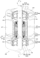
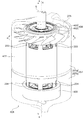
- FIG. 2 is a transparent perspective view of the rotating device 201 according to the second embodiment of the present invention
- FIG. 3 is a transparent sectional view of a cross section of the rotating device 201 including the axis x.
- the housing 207 is shown in a transparent state by being drawn by an imaginary line (dashed line).
- FIG. 4 is a cross-sectional view of a cross section (AA cross section in FIG. 2) perpendicular to the axis x direction of the rotating device 201.
- the imaginary line indicating the housing 207 is omitted.
- members having the same configuration as that of the first embodiment are designated by the same reference numerals, and detailed description thereof will be omitted.
- the suction port and the discharge port described in the following embodiments are ventilation ports, and are described as the suction port and the discharge port for convenience because they correspond to the direction of air. Depending on the direction of the air, the suction port becomes a suction port, the discharge port also becomes a suction port, and the description of the suction port and the discharge port in each embodiment does not limit the present invention.
- the housing 207 is composed of two members, a tubular first housing (hereinafter referred to as an upper housing) 207a and a second housing (hereinafter referred to as a lower housing) 207b. Will be done.
- the integrated housing 207 is configured by fitting and fixing the upper housing 207a and the lower housing 207b as shown in FIGS. 2 and 3.
- a part of the components of the rotating device 201 is housed inside the housing 207, and the shaft member 5 is fixed to the upper end portion of the upper housing 207a and the lower end portion of the lower housing 207b.
- the housing 207 and the shaft member 5 form a member on the fixed side.
- an upper end opening 275 and a lower end opening 276 are provided at the upper end of the upper housing 207a and the lower end of the lower housing 207b, and the upper opening 275 and the lower opening 276 each surround the shaft member 5. ..
- the moving blade 206 is attached to the central portion in the axis x direction on the outer peripheral surface of the rotor 203.
- the moving blade 206 is provided with a plurality of blades 262 at predetermined intervals on the outer peripheral surface of the tubular portion 261 and extends radially. Further, as shown in FIG. 4, when viewed from one side in the x-direction of the axis (upper side a in FIG. 4), a part of the respective blades 206 overlaps and is arranged without a gap. ..
- the rotor blade 206 rotates together with the rotor 203, and the rotated rotor blade 206 causes an air flow according to the rotation of the rotor blade 206. This air flow is generated in the space 277 between the housing 207 and the rotor 203 toward either the upward direction or the downward direction in the axial direction of the shaft member 5.
- the rotating device 201 is driven to rotate the moving blade 206 in the clockwise direction e so that the air taken in from the upper end opening 275 is blown out from the lower end opening 276. It is configured.
- the moving blade 206 is arranged at the center of the outer peripheral surface of the rotor 203 (rotating body).
- the vibration generated in the rotor 203 is difficult to propagate to the housing 1207, and the vibration generated in the rotor 203 is difficult to propagate to the housing 1207. The generation of vibration can be suppressed.
- the tubular member 232 of the rotor 203 is provided with a suction port 233 as a vent and a discharge port 234 as a vent.
- the suction port 233 is provided in the portion of the tubular member 232 between the first bearing (bearing) 41 and the moving blade 206.
- the discharge port 234 is provided in the portion of the tubular member 232 between the second bearing (bearing) 42 and the moving blade 206.
- the suction port 233 and the discharge port 234 are formed in a rectangular shape having a longitudinal ef in the circumferential direction.
- the plurality of suction ports 233 and the plurality of discharge ports 234 are arranged at equal intervals in the circumferential direction ef.
- the suction port 233 may be the discharge port
- the discharge port 234 may be the suction port.
- the rotating device 201 in the rotating device 201 according to the present embodiment, a large amount of cooling air can be sent into the rotor 203, and the stator 2 including the heated coil can be efficiently cooled.
- the same action occurs and the same effect is exhibited with respect to the same configuration as in the first embodiment.
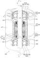
- FIG. 5 is a transparent perspective view of the rotating device 301 according to the third embodiment which is an example of the present invention
- FIG. 6 is a transparent sectional view of a cross section of the rotating device 301 including the axis x.
- members having the same configuration as those of the first to second embodiments are designated by the same reference numerals, and detailed description thereof will be omitted.
- a configuration different from the above-described embodiment will be mainly described in the present embodiment.
- the two moving blades 306a and 306b are attached to the outer peripheral surface of the rotor 303 at two locations above and below the axis x direction.
- the rotor blades 306a and 306b have the same shape, and similarly to the rotor blades 206 in the second embodiment, a plurality of blades 362a and 362b are radially provided at predetermined intervals on the outer periphery of the tubular portions 361a and 361b. It is a configuration. Other configurations are the same as those of the moving blade 206 in the second embodiment.
- the moving blades 306a and 306b rotate together with the rotor 303, and the rotation of the moving blades 306a and 306b causes an air flow, so that the air flows in the space 377 in either the vertical direction.
- the rotating device 301 of the present embodiment the rotating device 301 is driven to rotate the moving blades 306a and 306b in the clockwise direction e, so that the air taken in from the upper end opening 275 is blown out from the lower end opening 276. It is configured as follows.
- the moving blades 306a are arranged on the outer peripheral surface of the tubular member 332 on the housing 377 side with respect to the bearing 41. Further, in the radial direction of the rotor 203, the moving blades 306b are arranged on the outer peripheral surface of the tubular member 332 on the housing 377 side with respect to the bearing 42. Further, these rotor blades 306a and rotor blades 306b are arranged equidistant from the central portion of the rotor 203 (rotating body) in the axial direction (axis x direction) of the shaft member 5.
- the position of the moving blade 306a and the position of the first bearing 41 overlap, and the position of the moving blade 306b and the position of the second bearing 42 overlap. ..
- the moving blade 306a By arranging the moving blade 306a at a position that overlaps with the position of the first bearing 41 at least in part, the moving blade 306a can be brought closer to the upper end opening 275 on the air intake side, and the air suction efficiency can be improved.
- the moving blade 306b at a position where it overlaps with the position of the second bearing 42 at least in part, the moving blade 306b can be brought closer to the lower end opening 276 on the air blowing side, and the air blowing efficiency can be improved.
- the suction port 233 is located at the position on the moving blade 306b side with respect to the moving blade 306a. Is provided, and a discharge port 234 is provided at a position on the moving blade 306a side with respect to the moving blade 306b.
- the air taken in from the upper end opening 275 and sent by the moving blade 306a has a relatively high pressure in a region that is a part of the space 277 on the moving blade 306b side with respect to the moving blade 306a.
- the suction port 233 is provided in the region where the pressure is relatively high, the flow of air passing between the housing 377 and the rotor 303 (hereinafter, may be referred to as "main air flow")
- the cooling air inside the rotor 203 (hereinafter, may be simply referred to as “cooling air”) is efficiently inside the rotor 203 so as to be pushed into the space inside the rotor 203 from the suction port 233. Is sucked into.
- the rotating device 301 according to the present embodiment, more cooling air can be sent into the rotor 203, and the stator 2 provided with the heating coil can be cooled more efficiently.
- the same action occurs and the same effect is exhibited with respect to the same configuration as that of the first embodiment or the second embodiment.
- FIG. 7 is a transparent perspective view of the rotating device 401 according to the fourth embodiment of the present invention
- FIG. 8 is a transparent sectional view of a cross section of the rotating device 401 including the axis x.
- the members having the same configuration as those of the first to second embodiments are designated by the same reference numerals, and detailed description thereof will be omitted. In the following description, the configuration peculiar to the present embodiment will be mainly described.
- the moving blade 406 is attached to the upper portion (bearing 406 side) in the axis x direction on the outer peripheral surface of the rotor 403.
- the rotor blade 406 is the same as the rotor blade 206 in the second embodiment, and a plurality of blades 462 are arranged at predetermined intervals on the outer peripheral surface of the tubular portion 461, and the rotor blades 406 extend radially in the radial direction. is there.
- Other configurations are the same as those of the moving blade 206 in the second embodiment.
- the position of the moving blade 406 overlaps with the position of the bearing 41 in the axial direction (axis x direction) of the shaft member 5, and a part of the moving blade 406 is in the radial direction. It faces the bearing 41 via the tubular member 232.
- a ring member 409 hereinafter, referred to as a balance ring
- the position of the balance ring 409 overlaps with the position of the bearing 42, and a part of the balance ring 409 faces the bearing 42 via the tubular member 232 in the radial direction.
- the balance ring 409 is arranged at a position symmetrical to the moving blade 406 with the central portion of the rotor 203 (rotating body) as the center.
- the weight of the balance ring 409 is adjusted so that the weights at both ends of the rotor 203 are the same in the axial direction of the shaft member 5.
- the weight of the balance ring is adjusted to be the same as the rotor blade 406.
- the balance ring is formed of a weight member such as a resin member or a metal member.
- the position of the moving blade 406 and the position of the first bearing 41 overlap.
- the moving blade 406 can be brought closer to the upper end opening 275 on the air intake side, and the air suction efficiency can be improved.
- a suction port 233 is provided.
- the rotating device 401 according to the present embodiment, more cooling air can be sent into the internal space of the rotor 203, and the stator 2 having the heated coil can be cooled more efficiently.
- the same action occurs and the same effect is exhibited with respect to the same configuration as that of the first embodiment or the second embodiment.
- FIG. 9 is a cross-sectional view of a cross section including the axis x of the rotating device 501 according to the fifth embodiment of the present invention. Further, FIG. 10 is a cross-sectional view of a cross section (BB cross section in FIG. 9) perpendicular to the axis x direction of the rotating device 501.
- FIGS. 9 and 10 the same reference numerals are given to the members having the same configuration as that of the third embodiment (furthermore, the first embodiment to the second embodiment). , The detailed description thereof will be omitted. In the following description, the configuration peculiar to the present embodiment will be mainly described.
- the housing 507 includes a concave first housing (hereinafter referred to as an upper housing) 507a, a tubular second housing (hereinafter referred to as a middle housing) 507b, and a concave third housing. It is composed of three members of a housing (hereinafter referred to as a lower housing) 507c. Further, in the upper housing 507a, an upper end opening 275 is formed at the upper portion serving as one end of the housing 507.
- an upper housing 507a an upper end opening 275 is formed at the upper portion serving as one end of the housing 507.
- a lower end opening 276 is formed at the lower portion of the housing 507, which is the other end portion.
- the integrated housing 507 is configured by fitting and fixing the upper housing 507a, the middle housing 507b and the lower housing 507c as shown in FIG.
- the moving blade 306a is arranged so as to be surrounded by the upper housing 507a.
- the rotor blades 306b are arranged so as to be surrounded by the lower housing 507c. Therefore, if the configuration is the same as that of the third embodiment, the space 577 between the middle housing 507b and the rotor 203 has a cavity that is an open space.
- a stationary wing 579 is provided in this space 577.
- the stationary blade 579 is, for example, a part of the inner peripheral surface of the housing 307 located between the two moving blades 306a and 306b, or a housing located between the moving blade 406 and the balance ring 409 in the fourth embodiment. It is provided on a part of the inner peripheral surface of the 207, and such a stationary blade is hereinafter referred to as an "intermediate stationary blade".
- the intermediate vane 579 extends from a part of the inner peripheral surface of the middle housing 507b toward the axis x direction, and extends from a part of the inner peripheral surface of the middle housing 507b toward the rotor 203. It extends. Further, the intermediate stationary blades 579 have a plate-like shape formed by a plane parallel to the axis x, and a plurality of intermediate vanes 579 are provided at equal intervals in the circumferential ef direction (8 in the present embodiment).
- the space 577 is provided with a plurality of (eight in the present embodiment) wind passages (hereinafter, "air passages") along the flow path through which air flows by the plurality of intermediate stationary blades 579. It is divided into.). According to the present embodiment, the space 577 is divided into a plurality of air passages by the intermediate stationary blade 579, so that the air flow is rectified and the air volume can be increased.
- air passages wind passages
- the cylinder member 232 of the rotor 203 is provided with a suction port 233 and a discharge port 234, respectively.
- FIG. 11 shows an explanatory diagram for explaining the flow of cooling air into the rotor 3.
- FIG. 11 is a transmission cross-sectional view similar to that of FIG.
- the suction port 233 is located at the position on the moving blade 306b side with respect to the moving blade 306a.
- the discharge port 234 is provided at a position on the moving blade 306a side with respect to the moving blade 306b.
- the position of the suction port 233 overlaps the position of the upper end portion of the intermediate stationary blade 579, and the position of the discharge port 234 overlaps the position of the lower end portion of the intermediate stationary blade 579. ..
- the air taken in from the upper end opening 275 and sent by the moving blade 306a flows to a part of the space 577 on the moving blade 306b side with respect to the moving blade 306a.
- the air that has flowed into this region is rectified by passing through a space partitioned by a plurality of intermediate vanes 579, and is rectified separately from the main air into the inside of the rotor 203 from the suction port 233 provided in this region. Is pushed in in a rectified state to cool the stator 2.
- the cooling air taken in from the suction port 233 was formed in the stator 2 while cooling the stator 2 composed of the stator core 21 and the coil 22 inside the rotor 203. It flows toward the bearing 42 through a gap (for example, a gap between a plurality of magnetic pole portions 23 and a gap G between the stator core 21 and the magnet 31).
- the air is sent out to the lower end opening 276 by the moving blade 306b and flows to a part of the space 277 on the moving blade 306a side with respect to the moving blade 306b.
- the air that has flowed into this region passes through the space partitioned by the plurality of intermediate vanes 579 and is rectified, and the air is discharged to the lower end opening 276 by the moving blades 306b. Therefore, as shown by the dotted arrow in FIG. 11, the main air is discharged more efficiently together with the cooling air discharged from the inside of the rotor 203.
- the rotating device 501 according to the present embodiment, more cooling air can be sent into the rotor 203, and the stator 2 having the heated coil can be cooled more efficiently.
- the same action occurs and the same effect is exhibited with respect to the same configuration as that of the first embodiment, the second embodiment, or the third embodiment.
- FIG. 12 is a transparent cross-sectional view of a cross section parallel to the axis x, which is cut off in front of the axis x of the rotating device 601 according to the sixth embodiment of the present invention.
- the rotating device 601 according to the present embodiment differs from the rotating device 501 according to the fifth embodiment only in the configuration of the stationary blades provided on the inner peripheral surface of the inner housing.
- FIG. 12 as in the fifth embodiment, the members having the same configuration as the third embodiment (furthermore, the first to second embodiments) are the same. Reference numerals will be given and detailed description thereof will be omitted. In the following description, the configuration peculiar to the present embodiment will be mainly described.
- the housing 607 in this embodiment is composed of three members: an upper housing 507a, a tubular middle housing 607b, and a lower housing 507c.
- the integrated housing 607 is configured by fitting and fixing the upper housing 507a, the middle housing 607b and the lower housing 507c as shown in FIG.
- FIG. 13 shows a cross section of the middle housing 607b extracted from the rotating device 601 according to the present embodiment together with the intermediate stationary blades (static blades) 679a and 679b provided on the inner peripheral surface thereof, and cut out in a cross section including the axis x.
- the intermediate stationary blades 679a and 679b have a plate-like shape as in the fifth embodiment, and extend from the inner peripheral surface of the middle housing 607b toward the axis x direction. ..
- the intermediate stationary blades 679a and 679b extend from the inner peripheral surface of the middle housing 607b toward the rotor 203.
- the intermediate vanes 679a and 679b have a surface inclined with respect to the axis x.
- the intermediate vane 679a is inclined counterclockwise (circumferential direction f) from above (a part of the middle housing 607b on the bearing 41 side) to below (the other part of the middle housing 607b on the bearing 42 side).
- the intermediate stationary blade 679b is provided and is provided so as to be inclined clockwise (circumferential direction e) from above to downward.
- the intermediate stationary blades 679a and the intermediate stationary blades 679b are alternately arranged in the circumferential direction ef, and the directions of inclination are staggered. Specifically, in the circumferential direction of the rotor 203, the position of one end 679a1 (the end on the bearing 41 or the moving blade 306a side) of the intermediate stationary blade 679a is the position of the other end (bearing 42 or the moving blade). It is different from the position of the end) on the 306b side.
- the position of one end 679b1 (bearing 41 or the end on the moving blade 306a side) of the intermediate stationary blade 679b is the other end 679b2 (bearing 42 or the moving blade 306b). It is different from the position of the end) on the side.
- one end 679a1 of the intermediate vane 679a is close to one end 679b1 of the intermediate vane 679b, and the other end 679a2 of the intermediate vane 679a is the intermediate vane. It is separated from the other end of 679b, 679b2.
- the distance between one end 679a1 of the intermediate stationary blade 679a and one end 679b1 of the intermediate stationary blade 679b is intermediate with the other end 679a2 of the intermediate stationary blade 679a. It is less than the distance between the other end of the vane 679b and the other end 679b2.
- the space 677 is partitioned into a plurality of (eight in this embodiment) air passages along the main air flow path.
- the space 677 is partitioned into a plurality of air passages 677x, 677y by the intermediate stationary blades 679a, 679b, so that the air flow is rectified and the air volume can be increased.
- the width of the air passage 677x between the intermediate stationary blade 679a and the adjacent intermediate stationary blade 679b on the circumferential direction f side of the rotor 203 in the circumferential direction is formed so as to narrow in the direction in which air flows.
- the width of the air passage 677y between the intermediate stationary blade 679a and the adjacent intermediate stationary blade 679b on the circumferential direction e side in the circumferential direction of the rotor 203 is formed so as to expand in the direction in which air flows. ing.
- the air passage 677x on the bearing 41 or the moving blade 306a side is narrow, and the air passage 677y on the bearing 42 or the moving blade 306b side is wide.
- vent 633 on the rotor blade 306b side with respect to the position of the rotor blades 306a A vent 634 is provided on the moving blade 306a side with respect to the position of the moving blade 306b.
- the vent 633 is the same as the suction port 233 in the second to fifth embodiments, and the vent 634 is the same as the discharge port 234 in the second to fifth embodiments.
- the position of the vent 633 overlaps with the position of the upper end of the intermediate vanes 679a and 679b, and the position of the vent 634 is the position of the lower end of the intermediate vanes 679a and 679b. It overlaps with.
- the air in the air passage 677y upstream (bearing 41 or rotor blade 306a side) is dense, and the air in the air passage 677y downstream (bearing 42 or rotor blade 306b side) is sparse. ing. Therefore, since the air passage 677y expands toward the downstream side, the air changes from a dense state to a sparse state and is expanded, and the pressure at the air passage 677y on the lower end side (bearing 42 or rotor blade 306b side). Becomes low pressure, and the pressure in the air passage 677y on the upper end side (bearing 41 or rotor blade 306a side) becomes relatively high.
- the air in the air passage 677y having a relatively high pressure is taken into the rotor 203 through the vent 633, and the air in the air passage 677y having a relatively low pressure is taken in.
- the air for cooling is discharged to the outside of the rotor 203 through the vent 634.
- the flow of cooling air passing through the vents 633 and 634 is in the opposite direction to the air passage 677y.
- the air in the air passage 677y downstream (bearing 42 or rotor blade 306b side) is dense, and the air in the air passage 677y upstream (bearing 41 or rotor blade 306a side) is sparse. ing.
- the air passage 677x expands toward the upstream, the air changes from a sparse state to a dense state and is compressed, so that the pressure at the air passage 677y on the lower end side (bearer 42 or rotor blade 306b side) is increased.
- the pressure becomes relatively high, and the pressure at the upper end side (bearer 41 or rotor blade 306a side) in the air passage 677y becomes relatively low. Due to this pressure difference, the air passage 677y becomes relatively high pressure.
- the air inside is taken into the rotor 203 through the vent 634, and the air inside the air passage 677y, which has a relatively low pressure, is cooled to the outside of the rotor 203 via the vent 633. Air is discharged.
- a plurality of intermediate stationary blades 679a and a plurality of intermediate stationary blades 679b which form an array in which two different tilting directions are arranged alternately in the circumferential direction ef, are used.
- the widths of the air passages 677x and 677y are gradually changing in the traveling direction of the air. Therefore, in each of the air passages 677x and 677y, a pressure difference occurs between the upstream and the downstream of the air flow.
- the cooling air is forced into the rotor 203 through the vents 633 and 634. It is designed to be taken in or discharged.
- the rotating device of the present invention has been described above with reference to preferred embodiments, the rotating device of the present invention is not limited to the configuration of the above embodiment.
- configurations specific to each embodiment may be combined.
- a configuration peculiar to the first embodiment a configuration in which a preload is applied to the inner peripheral ring 41b of the first bearing 41 by a disc spring 91, etc.
- a configuration peculiar to the first embodiment is applied to the second to sixth embodiments. It doesn't matter.
- intermediate stationary blades 579 and the intermediate stationary blades 679a and 679b peculiar to the fifth embodiment and the sixth embodiment described with reference to the example provided with the pair of upper and lower rotor blades 306a and 306b are used (housing 507 and housing 607). (With) may be applied to the fourth embodiment.
- the fourth embodiment there is a point where the upper rotor blade 406 and the lower balance ring 409 form a pair, and between the rotor blade 406 and the balance ring 409, an intermediate stationary blade 579 or an intermediate stationary blade 679,679b There is a space 477 in which the space can be provided.
- the air may be a gas such as a refrigerant.
- a gas such as a refrigerant.
Landscapes
- Engineering & Computer Science (AREA)
- Mechanical Engineering (AREA)
- General Engineering & Computer Science (AREA)
- Power Engineering (AREA)
- Physics & Mathematics (AREA)
- Geometry (AREA)
- Thermal Sciences (AREA)
- Structures Of Non-Positive Displacement Pumps (AREA)
- Motor Or Generator Frames (AREA)
- Connection Of Motors, Electrical Generators, Mechanical Devices, And The Like (AREA)
Priority Applications (5)
| Application Number | Priority Date | Filing Date | Title |
|---|---|---|---|
| US17/596,398 US20220235775A1 (en) | 2019-06-14 | 2020-06-12 | Rotating device |
| CN202410553710.0A CN118407924A (zh) | 2019-06-14 | 2020-06-12 | 旋转设备 |
| CN202080043778.4A CN113966440B (zh) | 2019-06-14 | 2020-06-12 | 旋转设备 |
| JP2021526170A JP7496353B2 (ja) | 2019-06-14 | 2020-06-12 | 回転機器 |
| JP2024085507A JP7752210B2 (ja) | 2019-06-14 | 2024-05-27 | 回転機器 |
Applications Claiming Priority (2)
| Application Number | Priority Date | Filing Date | Title |
|---|---|---|---|
| JP2019111612 | 2019-06-14 | ||
| JP2019-111612 | 2019-06-14 |
Publications (1)
| Publication Number | Publication Date |
|---|---|
| WO2020251041A1 true WO2020251041A1 (ja) | 2020-12-17 |
Family
ID=73781223
Family Applications (1)
| Application Number | Title | Priority Date | Filing Date |
|---|---|---|---|
| PCT/JP2020/023298 Ceased WO2020251041A1 (ja) | 2019-06-14 | 2020-06-12 | 回転機器 |
Country Status (4)
| Country | Link |
|---|---|
| US (1) | US20220235775A1 (https=) |
| JP (2) | JP7496353B2 (https=) |
| CN (2) | CN113966440B (https=) |
| WO (1) | WO2020251041A1 (https=) |
Cited By (2)
| Publication number | Priority date | Publication date | Assignee | Title |
|---|---|---|---|---|
| JP2022122724A (ja) * | 2021-02-10 | 2022-08-23 | ミネベアミツミ株式会社 | 回転機器 |
| WO2023099087A1 (de) * | 2021-12-03 | 2023-06-08 | Ebm-Papst St. Georgen Gmbh & Co. Kg | Ventilator mit zweiseitig gelagerter rotorwelle |
Families Citing this family (1)
| Publication number | Priority date | Publication date | Assignee | Title |
|---|---|---|---|---|
| JP6935252B2 (ja) * | 2017-07-10 | 2021-09-15 | ミネベアミツミ株式会社 | モータ |
Citations (2)
| Publication number | Priority date | Publication date | Assignee | Title |
|---|---|---|---|---|
| JP2008175158A (ja) * | 2007-01-19 | 2008-07-31 | Nippon Densan Corp | 軸流ファン |
| JP2017158409A (ja) * | 2016-03-04 | 2017-09-07 | 日本精工株式会社 | ローラ |
Family Cites Families (23)
| Publication number | Priority date | Publication date | Assignee | Title |
|---|---|---|---|---|
| US3385510A (en) * | 1966-07-29 | 1968-05-28 | Litton Prec Products Inc | Miniature motor driven air blower |
| US4995787A (en) * | 1989-09-18 | 1991-02-26 | Torrington Research Company | Axial flow impeller |
| US5101306A (en) * | 1989-10-30 | 1992-03-31 | Kabushiki Kaisha Toshiba | Releasable controlled force clamp for disk storage apparatus |
| DE4121428A1 (de) * | 1991-06-28 | 1993-01-07 | Papst Motoren Gmbh & Co Kg | Spindelmotor, insbesondere fuer plattenspeicher |
| US5519270A (en) * | 1992-08-19 | 1996-05-21 | Fujitsu Limited | Spindle motor and disk drive having the same |
| US5859745A (en) * | 1993-11-02 | 1999-01-12 | Seagate Technology, Inc. | Split ring mounting for disk drive spindle and actuator shafts |
| JPH07327347A (ja) * | 1994-05-30 | 1995-12-12 | Toshiba Corp | アウタロータ用ファンモータ |
| US6528909B1 (en) * | 1998-01-14 | 2003-03-04 | International Business Machines Corporation | Motor shaft having an integral heat pipe |
| JP3295842B2 (ja) * | 1998-07-16 | 2002-06-24 | ミネベア株式会社 | 軸流ファンモータ |
| US6707639B1 (en) * | 2000-03-31 | 2004-03-16 | Seagate Technology Llc. | Balancing system with adjustable eccentric rings for a disc drive assembly |
| EP1432104B1 (de) * | 2002-12-16 | 2006-12-06 | ebm-papst St. Georgen GmbH & Co. KG | Aussenläufermotor mit stehender Lagerachse |
| JP2005256705A (ja) * | 2004-03-11 | 2005-09-22 | Nippon Densan Corp | 細長遠心ファン |
| US7554228B2 (en) * | 2005-05-25 | 2009-06-30 | Hewlett-Packard Development Company, L.P. | Cooling fan with an outer rotor motor |
| CN100590949C (zh) * | 2006-04-14 | 2010-02-17 | 日本伺服有限公司 | 轴流风扇电动机 |
| JP3129498U (ja) * | 2006-08-11 | 2007-02-22 | 建軍 ▲兪▼ | 磁気浮上回転装置 |
| JPWO2008041353A1 (ja) * | 2006-09-29 | 2010-02-04 | 日本電産サンキョー株式会社 | ファンモータ |
| JP2009243381A (ja) * | 2008-03-31 | 2009-10-22 | Nidec Sankyo Corp | ファンモータ |
| JP2012097655A (ja) * | 2010-11-02 | 2012-05-24 | Nippon Densan Corp | 送風ファン |
| JP2012102686A (ja) * | 2010-11-11 | 2012-05-31 | Nippon Densan Corp | 送風ファン |
| JP2013015038A (ja) * | 2011-06-30 | 2013-01-24 | Nippon Densan Corp | ファン |
| US20140010645A1 (en) * | 2012-07-05 | 2014-01-09 | Adda Corp. | Fan structure |
| JP5910673B2 (ja) * | 2014-06-30 | 2016-04-27 | ダイキン工業株式会社 | 電動機 |
| JP6728948B2 (ja) * | 2016-05-09 | 2020-07-22 | 日本電産株式会社 | ファンモータ |
-
2020
- 2020-06-12 WO PCT/JP2020/023298 patent/WO2020251041A1/ja not_active Ceased
- 2020-06-12 US US17/596,398 patent/US20220235775A1/en active Pending
- 2020-06-12 CN CN202080043778.4A patent/CN113966440B/zh active Active
- 2020-06-12 CN CN202410553710.0A patent/CN118407924A/zh active Pending
- 2020-06-12 JP JP2021526170A patent/JP7496353B2/ja active Active
-
2024
- 2024-05-27 JP JP2024085507A patent/JP7752210B2/ja active Active
Patent Citations (2)
| Publication number | Priority date | Publication date | Assignee | Title |
|---|---|---|---|---|
| JP2008175158A (ja) * | 2007-01-19 | 2008-07-31 | Nippon Densan Corp | 軸流ファン |
| JP2017158409A (ja) * | 2016-03-04 | 2017-09-07 | 日本精工株式会社 | ローラ |
Cited By (2)
| Publication number | Priority date | Publication date | Assignee | Title |
|---|---|---|---|---|
| JP2022122724A (ja) * | 2021-02-10 | 2022-08-23 | ミネベアミツミ株式会社 | 回転機器 |
| WO2023099087A1 (de) * | 2021-12-03 | 2023-06-08 | Ebm-Papst St. Georgen Gmbh & Co. Kg | Ventilator mit zweiseitig gelagerter rotorwelle |
Also Published As
| Publication number | Publication date |
|---|---|
| JP7496353B2 (ja) | 2024-06-06 |
| US20220235775A1 (en) | 2022-07-28 |
| CN113966440A (zh) | 2022-01-21 |
| JPWO2020251041A1 (https=) | 2020-12-17 |
| CN118407924A (zh) | 2024-07-30 |
| CN113966440B (zh) | 2024-05-28 |
| JP7752210B2 (ja) | 2025-10-09 |
| JP2024103561A (ja) | 2024-08-01 |
Similar Documents
| Publication | Publication Date | Title |
|---|---|---|
| JP7752210B2 (ja) | 回転機器 | |
| US20180195526A1 (en) | Serial axial flow fan | |
| EP3760878B1 (en) | Electric blower, electric vacuum cleaner and hand dryer | |
| WO2013145684A1 (ja) | 回転電機 | |
| JPWO2009136574A1 (ja) | 回転電動機およびそれを用いた送風機 | |
| US20210050762A1 (en) | Electric blower, electric vacuum cleaner, and hand drier | |
| US20070140844A1 (en) | Axial Flow Fan | |
| JP7781222B2 (ja) | 回転機器 | |
| JPWO2018216667A1 (ja) | ロータ及び当該ロータを有するモータ | |
| US20190195231A1 (en) | Centrifugal fan | |
| JPWO2020251041A5 (https=) | ||
| WO2021029309A1 (ja) | 回転機器 | |
| JP7808167B2 (ja) | 回転機器 | |
| JP4532964B2 (ja) | 二重回転子電動機 | |
| JP7288220B2 (ja) | モータ、送風装置、および冷凍装置 | |
| JP7591369B2 (ja) | 回転機器 | |
| TWI653808B (zh) | 微型馬達及其風扇 | |
| JPH10257719A (ja) | 小型モータ | |
| JP2022156437A (ja) | 回転電機のロータ | |
| US20250109750A1 (en) | Motor and fan motor | |
| CN110138107B (zh) | 内定子组件以及叶片与外转子一体化风机 | |
| JP2022122724A (ja) | 回転機器 | |
| JPH08205439A (ja) | モータ | |
| CN102148554A (zh) | 内转子式马达及其爪极件 | |
| WO2018159349A1 (ja) | モータ、動力装置、及びブルドーザ |
Legal Events
| Date | Code | Title | Description |
|---|---|---|---|
| 121 | Ep: the epo has been informed by wipo that ep was designated in this application |
Ref document number: 20822020 Country of ref document: EP Kind code of ref document: A1 |
|
| ENP | Entry into the national phase |
Ref document number: 2021526170 Country of ref document: JP Kind code of ref document: A |
|
| NENP | Non-entry into the national phase |
Ref country code: DE |
|
| 122 | Ep: pct application non-entry in european phase |
Ref document number: 20822020 Country of ref document: EP Kind code of ref document: A1 |