WO2020249993A1 - 車両の走行制御方法及び走行制御装置 - Google Patents
車両の走行制御方法及び走行制御装置 Download PDFInfo
- Publication number
- WO2020249993A1 WO2020249993A1 PCT/IB2019/000625 IB2019000625W WO2020249993A1 WO 2020249993 A1 WO2020249993 A1 WO 2020249993A1 IB 2019000625 W IB2019000625 W IB 2019000625W WO 2020249993 A1 WO2020249993 A1 WO 2020249993A1
- Authority
- WO
- WIPO (PCT)
- Prior art keywords
- vehicle
- lane
- target
- approach space
- traveling
- Prior art date
- Legal status (The legal status is an assumption and is not a legal conclusion. Google has not performed a legal analysis and makes no representation as to the accuracy of the status listed.)
- Ceased
Links
Images


Classifications
-
- B—PERFORMING OPERATIONS; TRANSPORTING
- B60—VEHICLES IN GENERAL
- B60W—CONJOINT CONTROL OF VEHICLE SUB-UNITS OF DIFFERENT TYPE OR DIFFERENT FUNCTION; CONTROL SYSTEMS SPECIALLY ADAPTED FOR HYBRID VEHICLES; ROAD VEHICLE DRIVE CONTROL SYSTEMS FOR PURPOSES NOT RELATED TO THE CONTROL OF A PARTICULAR SUB-UNIT
- B60W30/00—Purposes of road vehicle drive control systems not related to the control of a particular sub-unit, e.g. of systems using conjoint control of vehicle sub-units
- B60W30/18—Propelling the vehicle
- B60W30/18009—Propelling the vehicle related to particular drive situations
- B60W30/18163—Lane change; Overtaking manoeuvres
-
- B—PERFORMING OPERATIONS; TRANSPORTING
- B60—VEHICLES IN GENERAL
- B60W—CONJOINT CONTROL OF VEHICLE SUB-UNITS OF DIFFERENT TYPE OR DIFFERENT FUNCTION; CONTROL SYSTEMS SPECIALLY ADAPTED FOR HYBRID VEHICLES; ROAD VEHICLE DRIVE CONTROL SYSTEMS FOR PURPOSES NOT RELATED TO THE CONTROL OF A PARTICULAR SUB-UNIT
- B60W60/00—Drive control systems specially adapted for autonomous road vehicles
- B60W60/001—Planning or execution of driving tasks
- B60W60/0027—Planning or execution of driving tasks using trajectory prediction for other traffic participants
- B60W60/00272—Planning or execution of driving tasks using trajectory prediction for other traffic participants relying on extrapolation of current movement
-
- B—PERFORMING OPERATIONS; TRANSPORTING
- B60—VEHICLES IN GENERAL
- B60W—CONJOINT CONTROL OF VEHICLE SUB-UNITS OF DIFFERENT TYPE OR DIFFERENT FUNCTION; CONTROL SYSTEMS SPECIALLY ADAPTED FOR HYBRID VEHICLES; ROAD VEHICLE DRIVE CONTROL SYSTEMS FOR PURPOSES NOT RELATED TO THE CONTROL OF A PARTICULAR SUB-UNIT
- B60W30/00—Purposes of road vehicle drive control systems not related to the control of a particular sub-unit, e.g. of systems using conjoint control of vehicle sub-units
- B60W30/10—Path keeping
-
- B—PERFORMING OPERATIONS; TRANSPORTING
- B60—VEHICLES IN GENERAL
- B60W—CONJOINT CONTROL OF VEHICLE SUB-UNITS OF DIFFERENT TYPE OR DIFFERENT FUNCTION; CONTROL SYSTEMS SPECIALLY ADAPTED FOR HYBRID VEHICLES; ROAD VEHICLE DRIVE CONTROL SYSTEMS FOR PURPOSES NOT RELATED TO THE CONTROL OF A PARTICULAR SUB-UNIT
- B60W30/00—Purposes of road vehicle drive control systems not related to the control of a particular sub-unit, e.g. of systems using conjoint control of vehicle sub-units
- B60W30/18—Propelling the vehicle
- B60W30/18009—Propelling the vehicle related to particular drive situations
- B60W30/18154—Approaching an intersection
-
- B—PERFORMING OPERATIONS; TRANSPORTING
- B60—VEHICLES IN GENERAL
- B60W—CONJOINT CONTROL OF VEHICLE SUB-UNITS OF DIFFERENT TYPE OR DIFFERENT FUNCTION; CONTROL SYSTEMS SPECIALLY ADAPTED FOR HYBRID VEHICLES; ROAD VEHICLE DRIVE CONTROL SYSTEMS FOR PURPOSES NOT RELATED TO THE CONTROL OF A PARTICULAR SUB-UNIT
- B60W40/00—Estimation or calculation of non-directly measurable driving parameters for road vehicle drive control systems not related to the control of a particular sub unit, e.g. by using mathematical models
- B60W40/10—Estimation or calculation of non-directly measurable driving parameters for road vehicle drive control systems not related to the control of a particular sub unit, e.g. by using mathematical models related to vehicle motion
- B60W40/114—Yaw movement
-
- B—PERFORMING OPERATIONS; TRANSPORTING
- B60—VEHICLES IN GENERAL
- B60W—CONJOINT CONTROL OF VEHICLE SUB-UNITS OF DIFFERENT TYPE OR DIFFERENT FUNCTION; CONTROL SYSTEMS SPECIALLY ADAPTED FOR HYBRID VEHICLES; ROAD VEHICLE DRIVE CONTROL SYSTEMS FOR PURPOSES NOT RELATED TO THE CONTROL OF A PARTICULAR SUB-UNIT
- B60W60/00—Drive control systems specially adapted for autonomous road vehicles
- B60W60/001—Planning or execution of driving tasks
- B60W60/0027—Planning or execution of driving tasks using trajectory prediction for other traffic participants
- B60W60/00274—Planning or execution of driving tasks using trajectory prediction for other traffic participants considering possible movement changes
-
- B—PERFORMING OPERATIONS; TRANSPORTING
- B60—VEHICLES IN GENERAL
- B60W—CONJOINT CONTROL OF VEHICLE SUB-UNITS OF DIFFERENT TYPE OR DIFFERENT FUNCTION; CONTROL SYSTEMS SPECIALLY ADAPTED FOR HYBRID VEHICLES; ROAD VEHICLE DRIVE CONTROL SYSTEMS FOR PURPOSES NOT RELATED TO THE CONTROL OF A PARTICULAR SUB-UNIT
- B60W2420/00—Indexing codes relating to the type of sensors based on the principle of their operation
- B60W2420/40—Photo, light or radio wave sensitive means, e.g. infrared sensors
- B60W2420/403—Image sensing, e.g. optical camera
-
- B—PERFORMING OPERATIONS; TRANSPORTING
- B60—VEHICLES IN GENERAL
- B60W—CONJOINT CONTROL OF VEHICLE SUB-UNITS OF DIFFERENT TYPE OR DIFFERENT FUNCTION; CONTROL SYSTEMS SPECIALLY ADAPTED FOR HYBRID VEHICLES; ROAD VEHICLE DRIVE CONTROL SYSTEMS FOR PURPOSES NOT RELATED TO THE CONTROL OF A PARTICULAR SUB-UNIT
- B60W2552/00—Input parameters relating to infrastructure
- B60W2552/10—Number of lanes
-
- B—PERFORMING OPERATIONS; TRANSPORTING
- B60—VEHICLES IN GENERAL
- B60W—CONJOINT CONTROL OF VEHICLE SUB-UNITS OF DIFFERENT TYPE OR DIFFERENT FUNCTION; CONTROL SYSTEMS SPECIALLY ADAPTED FOR HYBRID VEHICLES; ROAD VEHICLE DRIVE CONTROL SYSTEMS FOR PURPOSES NOT RELATED TO THE CONTROL OF A PARTICULAR SUB-UNIT
- B60W2552/00—Input parameters relating to infrastructure
- B60W2552/53—Road markings, e.g. lane marker or crosswalk
-
- B—PERFORMING OPERATIONS; TRANSPORTING
- B60—VEHICLES IN GENERAL
- B60W—CONJOINT CONTROL OF VEHICLE SUB-UNITS OF DIFFERENT TYPE OR DIFFERENT FUNCTION; CONTROL SYSTEMS SPECIALLY ADAPTED FOR HYBRID VEHICLES; ROAD VEHICLE DRIVE CONTROL SYSTEMS FOR PURPOSES NOT RELATED TO THE CONTROL OF A PARTICULAR SUB-UNIT
- B60W2554/00—Input parameters relating to objects
- B60W2554/40—Dynamic objects, e.g. animals, windblown objects
- B60W2554/404—Characteristics
- B60W2554/4041—Position
-
- B—PERFORMING OPERATIONS; TRANSPORTING
- B60—VEHICLES IN GENERAL
- B60W—CONJOINT CONTROL OF VEHICLE SUB-UNITS OF DIFFERENT TYPE OR DIFFERENT FUNCTION; CONTROL SYSTEMS SPECIALLY ADAPTED FOR HYBRID VEHICLES; ROAD VEHICLE DRIVE CONTROL SYSTEMS FOR PURPOSES NOT RELATED TO THE CONTROL OF A PARTICULAR SUB-UNIT
- B60W2554/00—Input parameters relating to objects
- B60W2554/40—Dynamic objects, e.g. animals, windblown objects
- B60W2554/404—Characteristics
- B60W2554/4049—Relationship among other objects, e.g. converging dynamic objects
-
- B—PERFORMING OPERATIONS; TRANSPORTING
- B60—VEHICLES IN GENERAL
- B60W—CONJOINT CONTROL OF VEHICLE SUB-UNITS OF DIFFERENT TYPE OR DIFFERENT FUNCTION; CONTROL SYSTEMS SPECIALLY ADAPTED FOR HYBRID VEHICLES; ROAD VEHICLE DRIVE CONTROL SYSTEMS FOR PURPOSES NOT RELATED TO THE CONTROL OF A PARTICULAR SUB-UNIT
- B60W2554/00—Input parameters relating to objects
- B60W2554/40—Dynamic objects, e.g. animals, windblown objects
- B60W2554/406—Traffic density
Definitions
- the present invention relates to a vehicle travel control method and a travel control device that control the behavior of the own vehicle capable of autonomously traveling.
- Patent Document 1 it is assumed that the congested convoy overflows from the entrance of the branch road, but it is not assumed that various traffic jam situations may occur at the branch road.
- the tail end of the congested convoy does not overflow from the branch road entrance, the space where the own vehicle can enter the branch road is small, and a part of the vehicle body is in the adjacent traveling lane at the tail end position. It is not taken into consideration when the vehicle sticks out or when the vehicle cannot enter the branch road without tilting the direction of the vehicle. Therefore, when the own vehicle changes lanes, there is a risk that the vehicle cannot travel properly according to the actual traffic congestion in the other lane to which the lane is changed.
- An object to be solved by the present invention is to provide a vehicle travel control method and a travel control device capable of controlling the behavior of the own vehicle according to various traffic congestion situations that may occur in another lane to which the lane is changed. Is.
- the present invention detects an approach space existing behind another vehicle in the other lane when it is determined that there is congestion in another lane on the planned travel route, and determines that the approach space meets a predetermined condition.
- the above problem is solved by setting the target posture of the own vehicle at the target position based on the shape of the approach space.
- the target lane of the own vehicle is set in the other lane of the lane change destination. It is possible to control the behavior of the own vehicle according to various possible traffic conditions.
- FIG. It is a figure which shows an example of the target posture of the own vehicle set by the traveling control device shown in FIG. It is a figure which shows an example of the target posture of the own vehicle set by the traveling control device shown in FIG. It is a block diagram which shows the structure of the traveling control apparatus which concerns on 2nd Embodiment of this invention. It is a figure which shows an example of the target posture of the own vehicle set by the traveling control device shown in FIG. It is a figure which shows an example of the target posture of the own vehicle set by the traveling control device shown in FIG. It is a figure which shows an example of the target posture of the own vehicle set by the traveling control device shown in FIG. It is a figure which shows an example of the target posture of the own vehicle set by the traveling control device shown in FIG.
- FIG. 1 is a block diagram showing a configuration of a travel control system 101 including a travel control device 100.
- the vehicle travel control method and the vehicle travel control device 100 according to the present invention support the behavior of the actuator 21 of the own vehicle 9 by a computer based on the surrounding conditions of the own vehicle 9 that autonomously travels. It is a running control method and a running control device.
- the travel control device 100 is composed of one or more computers and software installed on the computers.
- the travel control device 100 includes a ROM that stores a program for executing automatic driving control for autonomously traveling the own vehicle 9, a CPU that executes the program stored in the ROM, and an accessible storage device. It consists of a RAM that functions as.
- the operating circuit MPU, DSP, ASIC, FPGA or the like can be used instead of or in combination with the CPU.
- the travel control device 100 is a vehicle 9 from the current location to the destination based on information from the navigation device 1, the map database 2, the vehicle position detector 3, the camera 4, the radar device 5, the vehicle speed sensor 6, and the input unit 7.
- the target travel locus of is calculated and determined.
- the target travel locus determined by the travel control device 100 is output as data including one or more lanes, a straight line, a course including a curve having a curvature or a traveling direction, or a combination thereof.
- the travel control device 100 calculates and outputs the control command value F to be output to the own vehicle 9 at predetermined time intervals based on the information of the target travel locus.
- the travel control device 100 controls the behavior of the actuator 21 of the own vehicle 9 based on the control command value F.
- the navigation device 1 selects from a display capable of displaying information on the current position of the own vehicle 9 and information such as a travel route to the destination, and the input destination and the current location detected by the own vehicle position detector 3. It is provided with a computer equipped with a program that calculates a traveling route according to the route calculation mode.
- the map database 2 stores three-dimensional high-definition map information based on the road shape detected when traveling on an actual road using a data acquisition vehicle.
- the three-dimensional high-definition map information stored in this map database 2 includes map information, boundary information at each map coordinate, two-dimensional position information, three-dimensional position information, road information, road attribute information, ascending information, descending information, and so on.
- Lane identification information, connection destination lane information, etc. are included.
- Road information and road attributes include road width, radius of curvature, shoulder structure, road traffic regulations (speed limit, lane changeability), road confluences, branch points, toll gates, lane reduction positions, service areas. / Contains information such as parking areas.
- the own vehicle position detector 3 is composed of a GPS unit, a gyro sensor, a vehicle speed sensor, and the like.
- the own vehicle position detector 3 detects radio waves transmitted from a plurality of satellite communications by the GPS unit, periodically acquires the position information of the own vehicle 9, and also acquires the acquired position information of the own vehicle 9 and a gyro sensor.
- the current position information of the own vehicle 9 is periodically detected based on the angle change information acquired from and the vehicle speed acquired from the vehicle speed sensor.
- the camera 4 is composed of an image sensor such as a CCD wide-angle camera, and is provided in the front and rear of the own vehicle 9 and on both sides as needed, and acquires image information by photographing the surroundings of the own vehicle 9.
- the camera 4 may be a stereo camera or an omnidirectional camera, and may include a plurality of image sensors. From the acquired image data, the camera 4 detects the road and structures around the road, road signs, signs, other vehicles, two-wheeled vehicles, bicycles, pedestrians, etc. in front of the own vehicle 9 as the surrounding conditions of the own vehicle 9. To do.
- the radar device 5 is provided on the front, rear, and both sides of the own vehicle 9, irradiates the periphery of the own vehicle 9 with millimeter waves or ultrasonic waves, scans a predetermined range around the own vehicle 9, and scans the predetermined range around the own vehicle 9. Detects obstacles such as other vehicles, two-wheeled vehicles, bicycles, pedestrians, curbs on the shoulder, guardrails, walls, and fillings that exist in the surrounding area. For example, the radar device 5 detects the relative position (direction) between the obstacle and the own vehicle 9, the relative speed of the obstacle, the distance from the own vehicle 9 to the obstacle, and the like as the surrounding conditions of the own vehicle 9.
- the vehicle speed sensor 6 measures the rotation speed of the drive system actuator of the own vehicle 9 such as a drive shaft, and detects the traveling speed of the own vehicle 9 based on this.
- the input unit 7 is composed of a mechanical switch, an electronic switch displayed on the display, and the like, and the driver inputs information such as a destination and a decision as to whether or not to perform automatic operation.
- the travel control device 100 estimates its own position based on the position information of its own vehicle 9 obtained by the own vehicle position detector 3 and the map information of the map database 2 (step S1). Further, the travel control device 100 recognizes pedestrians and other obstacles around the own vehicle 9 by the camera 4 and the radar device 5 (step S2). Then, the self-position information estimated in step S1 and the information such as obstacles recognized in step S2 are expanded and displayed on the map of the map database 2 (step S3).
- the destination is input from the input unit 7 and the start instruction of the autonomous driving control is input, the destination is set on the map of the map database 2 (step S4), and the navigation device 1 and the map database 2 are used. Then, route planning from the current location to the destination is performed (step S5). Then, the action of the own vehicle 9 is determined based on the information developed on the map (step S6). Specifically, for example, at each position of a plurality of intersections existing on the planned route, the direction in which the own vehicle 9 turns is determined. Next, drive zone planning is performed on the map of the map database 2 based on the information of obstacles and the like recognized by the camera 4 or the radar device 5 (step S7).
- the travel control device 100 sets the target travel locus of the own vehicle 9 based on the input position information of the current location and the destination, the set route information, the behavior of the own vehicle 9, and the drive zone information (Ste S8). Further, the travel control device 100 controls the behavior of the own vehicle 9 so that the own vehicle 9 follows the target travel locus (step S9).
- the travel control device 100 includes a lane planning unit 10, a track boundary acquisition unit 11, a branch determination unit 12, a surrounding condition detection unit 13, a traffic jam determination unit 14, a track boundary selection unit 15, an approach space detection unit 16a, and an approach space determination unit 16b. , Around obstacle detection unit 17, target posture setting unit 18, target travel locus generation unit 19, and route tracking control unit 20.
- the lane planning unit 10 of the travel control device 100 sets the lane plan of the own vehicle 9 based on the drive zone planning in step S7 of FIG. Based on this lane plan, the lane boundary acquisition unit 11 acquires the boundary of each lane of the planned travel route on which the own vehicle 9 should travel.
- the branch determination unit 12 determines whether or not there is a branch path in the planned travel route of the own vehicle 9.
- the branch determination unit 12 constitutes another lane determination unit.
- the surrounding situation detection unit 13 includes the camera 4 and the radar device 5, and detects the surrounding situation of the own vehicle 9 and the presence of other vehicles.
- the congestion determination unit 14 determines that the planned traveling route of the own vehicle 9 has a branch road
- the congestion on the branch road occurs based on the existence of other vehicles around the own vehicle 9 or the received congestion information. Determine if it is.
- the track boundary selection unit 15 finally owns the vehicle 9 based on the boundary of each lane of the planned travel route acquired by the track boundary acquisition unit 11 and the congestion state of the branch road determined by the congestion determination unit 14. Select the lane in which you will drive.
- the approach space detection unit 16a detects the approach space of the branch road based on the shape of the boundary of each lane of the planned travel route selected by the track boundary selection unit 15.
- the approach space is a space existing behind the other vehicle preceding the own vehicle 9 in the other lane of the lane change destination, and the own vehicle 9 can enter the other lane through the approach space.
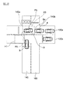
- the areas between the entrance boundary lines 35 and 135 of the branch road 30 and the rear end 8a of the preceding other vehicle 8 are designated as approach spaces A1 to A4, respectively.
- the entrance boundary lines 35 and 135 are branching portions between the branch road 30 and the traveling lane 40, and are boundaries that guide the vehicle entering the branch road 30 from the traveling lane 40 to the branch road 30.
- the approach space determination unit 16b determines whether or not the approach spaces A1 to A4 meet a predetermined condition set in advance.
- the predetermined condition means that, for example, the approach spaces A1 to A4 have the last section having a predetermined interval or more.
- the section between the rear end 8a of the other vehicle 8 which is the preceding vehicle lined up in the congested convoy of the branch road 30 and the entrance side lane end 36a of the branch road 30 is the last.
- the entrance-side lane end 36a of the branch road 30 refers to the entrance-side end of the region of the branch road 30 surrounded by a pair of boundaries 33 and 34 extending substantially parallel to each other.
- the "predetermined interval" is an interval in the lane direction of the branch road 30, and is an interval such that the own vehicle 9 can stop in a posture along the lane direction without tilting. ..
- the approach space determination unit 16b states that if the last section is shorter than the predetermined interval, "the last section of the predetermined interval or more". There is no "tail section", and it is determined that the approach spaces A1 to A4 meet the predetermined conditions.
- the approach spaces A1 and A2 do not have "the last sections of a predetermined interval or more". Therefore, it is determined that the approach spaces A1 and A2 meet the predetermined conditions.
- the target posture setting unit 18 shown in FIG. 3 sets the target posture of the own vehicle 9 at the target positions P1 to P4 at the end of the congested vehicle line based on the shapes of the approach spaces A1 to A4.
- the target posture is set as a posture in which the direction of the vehicle body of the own vehicle 9 is inclined at predetermined yaw angles ⁇ y1 to ⁇ y4 with respect to the lane direction of the branch road 30.
- the surrounding obstacle detection unit 17 includes the camera 4 and the radar device 5 as well as the surrounding condition detection unit 13, and detects obstacles around the own vehicle 9. Further, the target travel locus generation unit 19 generates target travel loci R1 to R4 based on information on the target posture, the target position, and surrounding obstacles of the own vehicle 9. Then, the route tracking control unit 20 controls the actuator 21 so that the own vehicle 9 travels following the target traveling loci R1 to R4.
- step S21 the congestion determination unit 14 of the travel control device 100 causes congestion in the branch road 30. Determine if it is.
- the branch road 30 is not congested, it is not necessary to set the target posture of the own vehicle 9, so the control ends.
- the control shifts to step S22, and the approach space determination unit 16b shows that the approach spaces A1 to A4 of the branch road 30 shown in FIGS. 5 to 8 meet the predetermined conditions.
- the approach space determination unit 16b determines that there is no trailing section of a predetermined interval or more between the entrance side lane ends 36a and 136a of the branch road 30 and the rear end 8a of the other vehicle 8.
- the approach spaces A1 to A4 meet the predetermined conditions.
- the branch road 30 has a trailing section of a predetermined interval or more, that is, when the approach space does not meet the predetermined condition, the own vehicle 9 does not tilt the vehicle body in a state of decelerating to a predetermined vehicle speed or less. Can fit in the approach space.
- the "state in which the own vehicle 9 has decelerated to a predetermined vehicle speed or less” includes a state in which the own vehicle 9 is temporarily stopped. Therefore, when the branch road 30 has a rearmost section having a predetermined interval or more and the approach space does not meet the predetermined condition, it is not necessary to set the target posture of the own vehicle 9, and the control ends.
- the travel control device 100 does not change the upper limit of the curvature of the own vehicle 9, maintains the upper limit of the curvature of the own vehicle 9 to a preset standard predetermined upper limit of the curvature, and keeps the own vehicle 9 Controls the behavior of the own vehicle 9 so that the vehicle travels in a straight posture along the lane direction of the branch road 30.
- the control shifts to step S23, and it is determined whether or not the inclination angle of the entrance boundary line of the branch road 30 is equal to or less than the predetermined threshold angle X. ..
- the entrance boundary lines 35 and 135 of the branch road 30 are the branch portions between the branch road 30 and the traveling lane 40, as shown in FIGS. 5 to 8, and the vehicle trying to enter the branch road 30 from the traveling lane 40. Is a boundary line that guides the vehicle to the branch road 30.
- the entrance boundary line 35 is inclined with respect to the lane direction of the branch road 30.
- the predetermined threshold angle X is, for example, 10 °.
- step S23 If it is determined in step S23 that the inclination angle of the entrance boundary line 35 of the branch road 30 is larger than the threshold angle X, control shifts to step S24, and the control proceeds along the branch road 30 to the opposite side of the traveling lane 40. It is determined whether or not the obstacle 50 as shown in FIG. 8 is provided.
- the obstacle 50 is, for example, a guardrail provided along the branch road 30, planting, or the like. If an obstacle 50 is provided along the branch road 30 on the opposite side of the traveling lane 40, the obstacle 50 is provided in front of the own vehicle 9 at the target position P4 at the end of the congested convoy. It will be in the state of being.
- step S24 when it is determined in step S24 that no obstacle is provided, the control shifts to step S26, and the target posture setting unit 18 targets the first target posture as shown in the examples of FIGS. 5 and 6. It is set as the target posture of the own vehicle 9 at the positions P1 and P2. Further, when it is determined in step S23 that the size of the inclination angle of the entrance boundary line 35 is equal to or less than the threshold angle X, the control shifts to step S25, and the target posture setting unit 18 is as shown in the example of FIG. The second target posture is set as the target posture of the own vehicle 9 at the target position P3.
- step S24 when it is determined in step S24 that the obstacle 50 is provided along the branch path 30, the control shifts to step S27, and the target posture setting unit 18 has a third target as shown in the example of FIG.
- the posture is set as the target posture of the own vehicle 9 at the target position P4.
- the first target posture, the second target posture, and the third target posture are target postures set based on different setting methods.
- step S28 the target travel locus generation unit 19 generates target travel loci R1 to R4 based on the target postures set in each of steps S25 to S27. Then, the path tracking control unit 20 raises the upper limit of the curvature of the own vehicle 9 in step S29, and controls the behavior of the own vehicle 9 according to the target traveling loci R1 to R4 in step S30.
- the upper limit of curvature is an upper limit value set to limit the curvature of the turning running of the own vehicle 9.
- the own vehicle 9 can travel along a target travel locus R1 to R4 different from the normal travel locus, and can take a target posture according to various yaw angles at target positions P1 to P4. become able to.
- the target travel loci R1 to R4 may be generated according to the target posture set based on the shapes of the approach spaces A1 to A4, respectively, or the travels simulated according to a plurality of curvatures. From the loci, loci that can realize the optimum target posture may be selected as the target traveling loci R1 to R4.
- the "optimal target posture" means, for example, that when the own vehicle 9 is in the approach spaces A1 to A4, the vehicle body does not protrude into the traveling lane 40, or the amount protruding into the traveling lane 40 is a predetermined amount or less. It means the attitude to become.
- the rearmost section L1 is shorter than a predetermined interval
- the approach space A1 meets a predetermined condition
- the inclination angle ⁇ 1 of the entrance boundary line 35 of the branch road 30 is a predetermined threshold angle. It is larger than X and no obstacle is provided along the branch road 30.
- the first target posture of the own vehicle 9 at the target position P1 behind the other vehicle 8 is a posture in which the direction of the vehicle body is inclined at a yaw angle ⁇ y1 with respect to the lane direction of the branch road 30.
- the target travel locus generation unit 19 of the travel control device 100 generates a target travel locus R1 from the current position of the own vehicle 9 to the target position P1.
- the route tracking control unit 20 raises the upper limit of the curvature of the own vehicle 9, and controls the behavior of the own vehicle 9 so that the own vehicle 9 follows the target traveling locus R1 and takes the first target posture at the target position P1.
- the target position P1 of the own vehicle 9 is set in the approach space A1.
- the rearmost section L2 is shorter than the predetermined interval, the approach space A2 meets the predetermined condition, and the inclination angle ⁇ 1 of the entrance boundary line 35 is predetermined, as in FIG. It is larger than the threshold angle X and no obstacle is provided along the branch path 30. Further, since the rearmost section L2 of the approach space A2 shown in FIG. 6 has a smaller interval than the last section L1 of the approach space A1 shown in FIG. 5, it is determined that the approach space A2 has a smaller space than the approach space A1. To. As shown in FIG.
- the yaw angle ⁇ y2 of the first target posture of the own vehicle 9 at the target position P2 becomes the same angle as the inclination angle ⁇ 1 of the entrance boundary line 35, and the first target The own vehicle 9 in the posture is inclined along the entrance boundary line 35. That is, when the first target posture is set for the own vehicle 9, the yaw angle of the first target posture of the own vehicle 9 changes according to the size of the approach spaces A1 and A2 of the branch road 30.
- the target travel locus generation unit 19 of the travel control device 100 generates the target travel locus R2 from the current position of the own vehicle 9 to the target position P2.
- the route tracking control unit 20 raises the upper limit of the curvature of the own vehicle 9, and controls the behavior of the own vehicle 9 so that the own vehicle 9 follows the target traveling locus R2 and takes the first target posture at the target position P2.
- the size of the approach spaces A1 and A2 may be judged not only by the length of the last sections L1 and L2 but also by the area or width of the approach spaces A1 and A2.
- the widths of the approach spaces A1 and A2 are the lengths of the approach spaces A1 and A2 in the direction perpendicular to the lane direction of the branch road 30, that is, in the width direction of the branch road 30.
- the travel control device 100 may determine the size of the approach spaces A1 and A2 based on the frontage lengths E1 and E2 of the approach spaces A1 and A2.
- the frontage lengths E1 and E2 of the approach spaces A1 and A2 are the lengths in the lane direction between the rear end 8a of the other vehicle 8 and the branch point 36b of the branch road 30. That is, the first target posture is set based on the shapes of the approach spaces A1 and A2.
- the shapes of the approach spaces A1 and A2 which are the criteria for setting the first target posture, include the areas and widths of the approach spaces A1 and A2, the intervals between the last sections L1 and L2, and the frontage lengths E1 and E2. Also includes the aspect ratio of the last sections L1 and L2 and the inclination angle ⁇ 1 of the entrance boundary line 35.
- the slope of the straight line connecting the start point and the end point of the entrance boundary line 35 is also included in the shapes of the entry spaces A1 and A2.
- FIG. 7 shows an example of the second target posture of the own vehicle 9.
- the approach space between the rear end 8a of the other vehicle 8 and the entrance boundary line 135 There is no last section in A3.
- the inclination angle ⁇ 2 of the entrance boundary line 135 of the branch path 30 is smaller than the predetermined threshold angle X.
- the target posture of the own vehicle 9 when temporarily stopping at the target position P3 behind the other vehicle 8 in the congested convoy is a posture in which the direction of the vehicle body is inclined at a yaw angle ⁇ y3 with respect to the lane direction of the branch road 30.
- the yaw angle ⁇ y3 of the target posture of the own vehicle 9 is set to be smaller than the inclination angle ⁇ 2 of the entrance boundary line 135.
- the target travel locus generation unit 19 of the travel control device 100 generates the target travel locus R3 from the current position of the own vehicle 9 to the target position P3.
- the route tracking control unit 20 controls the behavior of the own vehicle 9 so that the own vehicle 9 follows the target traveling locus R3 and takes the target posture at the target position P3.
- FIG. 8 shows an example of the third target posture of the own vehicle 9.
- the rearmost section L3 is shorter than a predetermined interval
- the inclination angle ⁇ 1 of the entrance boundary line 35 of the branch road 30 is larger than the predetermined threshold angle X
- the left side of the branch road 30 is larger than the predetermined threshold angle X
- An obstacle 50 is provided along the boundary 33 of the above.
- the obstacle 50 shall be a guardrail. Since the rearmost section L3 is shorter than the predetermined interval, the approach space A4 meets the predetermined condition.
- the target posture of the own vehicle 9 when temporarily stopping at the target position P4 behind the other vehicle 8 in the congested convoy is a posture in which the direction of the vehicle body is inclined at a yaw angle ⁇ y4 with respect to the lane direction of the branch road 30.
- the yaw angle ⁇ y4 of the third target posture is set to be smaller than the yaw angle when there is no obstacle 50 as shown in FIGS. 5 and 6. The higher the height of the obstacle 50, the smaller the yaw angle ⁇ y4 of the third target posture is set.
- the target travel locus generation unit 19 of the travel control device 100 generates the target travel locus R4 from the current position of the own vehicle 9 to the target position P4.
- the route tracking control unit 20 controls the behavior of the own vehicle 9 so that the own vehicle 9 follows the target traveling locus R4 and takes the target posture at the target position P4.
- the travel control device 100 when it is determined that there is a traffic jam in the branch road 30 adjacent to the travel lane 40, and the approach spaces A1 to A4 of the branch road 30 meet the predetermined conditions. In this case, the target posture of the own vehicle 9 at the target positions P1 to P4 behind the other vehicle 8 is set. As a result, the travel control device 100 can control the behavior of the own vehicle 9 according to various traffic congestion situations that may occur on the branch road 30.
- the travel control device 100 may fit in the approach spaces A1 to A4 in a state where the own vehicle 9 is decelerated below a predetermined vehicle speed without tilting the vehicle body. It is determined whether or not there is a trailing section that is longer than a predetermined interval that can be created. Then, when it is determined that the approach spaces A1 to A4 do not have the last section of the predetermined interval or more, the travel control device 100 determines that the approach spaces A1 to A4 meet the predetermined conditions. As a result, the travel control device 100 can set the optimum target posture of the own vehicle 9 at the target positions P1 to P4 even when the approach spaces A1 to A4 do not have a sufficient rearmost section.
- the own vehicle 9 can take a target posture in which the vehicle body is greatly tilted. It is possible to line up at the end of the congested convoy of the branch road 30 without protruding into the traveling lane 40.
- the travel control device 100 sets the target posture of the own vehicle 9 so that the larger the approach space A1, the closer the yaw angle ⁇ y1 is to 0 °. Set.
- the target posture of the own vehicle 9 can be set more appropriately according to the position of the other vehicle 8.
- the larger the approach space that is, the farther the position of the other vehicle 8 is, the closer the yaw angle of the target posture of the own vehicle 9 is to 0 °. Therefore, when the other vehicle 8 advances, the own vehicle 9 also It becomes possible to follow the other vehicle 8 and move along the branch road 30 more smoothly.
- the travel control device 100 enters.
- the target posture of the own vehicle 9 is set so that the yaw angle ⁇ y3 of the own vehicle 9 in the space A3 is smaller than the inclination angle ⁇ 2 of the entrance boundary line 135.
- the inclination angle ⁇ 2 of the entrance boundary line 135 of the branch road 30 is equal to or less than the threshold angle X
- the width of the approach space A3 at the target position P3 of the own vehicle 9 is narrow, and the inclination of the vehicle body of the own vehicle 9 is increased.
- the travel control device 100 sets the target posture of the own vehicle 9 so that the yaw angle ⁇ y3 of the own vehicle 9 is smaller than the inclination angle ⁇ 2 of the entrance boundary line 135, so that the vehicle body of the own vehicle 9 becomes excessively large. It prevents the vehicle from stopping behind the other vehicle 8 in an inclined posture, and minimizes the portion of the vehicle body of the own vehicle 9 that goes out to the traveling lane 40.
- the traveling control device 100 when the approach space A3 meets a predetermined condition and the inclination angle ⁇ 2 of the entrance boundary line 135 is equal to or less than the threshold angle X, the traveling control device 100 has a large approach space A3.
- the yaw angle ⁇ y3 of the own vehicle 9 is brought closer to 0 °.
- the travel control device 100 can reduce the portion of the vehicle body of the own vehicle 9 that may protrude into the traveling lane 40 as much as possible, and can adjust the target posture of the own vehicle 9 according to the position of the other vehicle 8. Can be set.
- the travel control device 100 has an obstacle.
- the target posture of the own vehicle 9 is set so that the yaw angle ⁇ y4 of the own vehicle 9 is smaller than when it is determined that the vehicle 9 is not provided.
- the own vehicle 9 is corrected to the obstacle.
- the occupants of the own vehicle 9 feel oppressive and anxious about the possibility of collision.
- the travel control device 100 sets the target posture so that the own vehicle 9 tilts at the target position P4, while suppressing an excessive tilting posture. Therefore, the feeling of oppression and anxiety felt by the occupants of the own vehicle 9 with respect to the obstacle 50 is reduced.
- the travel control device 100 sets the target posture so that the higher the height of the obstacle 50, the smaller the yaw angle ⁇ y4 of the own vehicle 9.
- the higher the height of the obstacle 50 provided in front the more easily the occupant of the own vehicle 9 feels oppressive to the obstacle 50.
- the yaw angle ⁇ y4 of the target posture of the own vehicle 9 is reduced, so that the feeling of oppression felt by the occupant of the own vehicle 9 can be reduced.
- the travel control device 100 sets the upper limit of the curvature of the own vehicle 9 higher than the preset predetermined upper limit of the curvature, and starts from the current position of the own vehicle 9.
- the target traveling loci R1 to R4 from the target positions P1 to P4 are generated.
- the own vehicle 9 travels along the target travel loci R1 to R4 different from the normal travel locus, and can take the target posture according to various yaw angles at the target positions P1 to P4. ..
- the travel control device 100 sets the approach space. It may be determined that A1 to A4 meet the predetermined conditions. Here, not only when the last sections L1 to L3 are shorter than the predetermined interval, but also when the area of the approach spaces A1 to A4 is less than or equal to the predetermined area or the width of the approach spaces A1 to A4 is less than or equal to the predetermined length. Even in this case, it is determined that "the own vehicle 9 cannot fit in the approach spaces A1 to A4 without tilting the vehicle body". As a result, the travel control device 100 can set various target postures of the own vehicle 9 in response to the case where the approach spaces A1 to A4 do not have sufficient space.
- the travel control device 100 when the own vehicle 9 travels based on the upper limit of the predetermined curvature and enters the approach spaces A1 to A4 in a state of decelerating to a predetermined vehicle speed or less, the vehicle body of the own vehicle 9 enters the traveling lane. It may be determined whether or not it is predicted that the amount exceeds a predetermined amount in 40. Then, the travel control device 100 determines that the approach spaces A1 to A4 meet the predetermined conditions when it is predicted that the vehicle body of the own vehicle protrudes into the traveling lane 40 by a predetermined amount or more. As a result, the travel control device 100 can set the target posture of the own vehicle 9 in advance so that the vehicle body of the own vehicle 9 does not protrude more than a predetermined amount into the traveling lane 40.
- Second Embodiment The vehicle travel control device 200 and the vehicle travelability control method using the vehicle travel control device 200 according to the second embodiment will be described with reference to FIGS. 9 to 12. Since the same reference numerals as those shown in FIGS. 1 to 8 indicate the same or similar configurations, detailed description thereof will be omitted.
- the travel control device 200 has another lane determination unit 112 in place of the branch determination unit 12 of the travel control device 100 according to the second embodiment.
- the other lane determination unit 112 determines whether or not there is a right turn lane 130a extending in the direction intersecting the traveling lane 140 in the planned traveling route calculated in advance (see FIGS. 10 to 12).
- the travel control device 200 has a turning travel region detection unit 118.
- the turning travel area detection unit 118 includes a camera 4 or a radar device 5.
- FIG. 10 shows an example in which the own vehicle 9 turns right at an intersection.
- the own vehicle 9 changes lanes from the current traveling lane 140 to the right turn lane 130a, which is another lane, across the left turn lane 130b.
- the right turn lane 130a and the left turn lane 130b are lanes extending in a direction intersecting the traveling lane 140.
- the approach space detection unit 16a of the travel control device 200 detects the approach space A5 in the right turn lane 130a.
- the approach space A5 is set as an area between the position of the left boundary line 140a of the traveling lane 140 and the rear end 8a of the other vehicle 8. That is, the shape of the approach space A5 changes depending on the position of the rear end 8a of the other vehicle 8.
- the approach space A5 has a length equal to or longer than a predetermined length in the lane direction of the right turn lane 130a, and the own vehicle 9 is in the approach space A5 of the target position P5 in the lane direction of the right turn lane 130a. You can line up in a straight line along the line.
- the approach space determination unit 16b determines whether or not the approach space A5 meets a predetermined condition set in advance.
- the predetermined condition in the example shown in FIG. 10 means that the rear end 8a of the other vehicle 8 that defines one end of the approach space A5 is behind the predetermined position.
- the predetermined position in this case is, for example, the position of the right boundary line 140b of the adjacent oncoming lane 160 of the traveling lane 140.
- the region of the left turn lane 130b required for the own vehicle 9 to swing its head and make a turning trip is defined as the turning running region H1.
- the turning traveling area detection unit 118 detects the turning traveling area H1 necessary for the own vehicle 9 to shake its head and make a turning traveling between the current position of the own vehicle 9 and the target position P5.
- the turning running area H1 since there is no other vehicle or obstacle in the turning running area H1, the turning running area H1 has sufficient space for the own vehicle 9 to shake its head and turn. It has a shape that can be secured.
- the target posture setting unit 18 sets the yaw angle of the target posture of the own vehicle 9 to 0 °. Then, the target traveling locus generation unit 19 takes a target traveling locus R5 from the current position of the own vehicle 9 to the target position P5 so that the own vehicle 9 takes a target posture along the lane direction of the right turn lane 130a at the target position P5. To generate.
- the route tracking control unit 20 raises the upper limit of the curvature of the own vehicle 9 and controls the behavior of the own vehicle 9 so that the own vehicle 9 follows the target traveling locus R5 and travels.
- the own vehicle 9 traveling along the target traveling locus R5 can enter the approach space A5 in the right turn lane 130a while shaking its head and making a sharp turn using the turning traveling region H1.
- FIG. 11 also shows an example in which the own vehicle 9 turns right at the intersection, as in FIG.
- the own vehicle 9 moves to the target position P6 behind the other vehicle 8 at the end of the congested convoy in the right turn lane 130a.
- the approach space detection unit 16a of the travel control device 200 detects the approach space A6 in the right turn lane 130a.
- the approach space determination unit 16b sets the approach space A6 to a predetermined condition. Judge that they do not match. Further, in the example shown in FIG. 11, the own vehicle 9 cannot fit in the approach space A6 unless the vehicle body is tilted.
- the target posture setting unit 18 sets the target posture of the own vehicle 9 as a posture tilted with respect to the lane direction of the right turn lane 130a.
- the yaw angle of the target posture of the own vehicle 9 is set as an angle equal to or less than the maximum angle that can be accommodated in the approach space A6.
- the target traveling locus generation unit 19 has a target traveling locus from the current position of the own vehicle 9 to the target position P6 so that the own vehicle 9 takes a target posture tilted with respect to the lane direction of the right turn lane 130a at the target position P6. Generate R6.
- the route tracking control unit 20 raises the upper limit of the curvature of the own vehicle 9 and controls the behavior of the own vehicle 9 so that the own vehicle 9 follows the target traveling locus R6.
- the own vehicle 9 traveling along the target traveling locus R6 can enter the approach space A6 in the right turn lane 130a while shaking its head and turning using the turning traveling region H2.
- the own vehicle 9 traveling along the target travel locus R6 makes a gentle turn compared to the own vehicle 9 traveling along the target travel locus R5 shown in FIG.
- FIG. 12 shows an example in which the own vehicle 9 turns right at a T-junction.
- the own vehicle 9 moves to the target position P7 or P8 behind the other vehicle 8 at the end of the congested convoy in the right turn lane 130a.
- a curb 150 is provided on the sidewalk side of the right turn lane 130a, and the surrounding obstacle detection unit 17 detects the curb 150 as an obstacle.
- the approach space detection unit 16a of the travel control device 200 detects the approach space A7 or A8 in the right turn lane 130a.
- the approach space A7 and the approach space A8 have different shapes based on the difference in the setting of the detection standard of the approach space by the approach space detection unit 16a.
- the approach space A7 is set as an area between the position of the boundary line 140c between the traveling lane 140 and the adjacent oncoming lane 160 and the rear end 8a of the other vehicle 8.
- the approach space A8 is set as an area between the position of the left boundary line 140a of the traveling lane 140 and the rear end 8a of the other vehicle 8. That is, the shape of the approach space differs depending on the difference in the detection criteria of the approach space.
- the approach space determination unit 16b determines that the approach space A7 or A8 is It is determined that the predetermined conditions are not met.
- the own vehicle 9 cannot fit in the approach space A7 unless the vehicle body is tilted, but the own vehicle 9 can fit in the approach space A8 in a straight posture along the lane direction of the right turn lane 130a.
- the turning traveling area detection unit 118 detects the turning traveling area H1 necessary for the own vehicle 9 to shake its head and make a turning run between the current position of the own vehicle 9 and the target position P7 or P8.
- the target posture setting unit 18 sets the target posture of the own vehicle 9 at the target position P7 with respect to the lane direction of the right turn lane 130a based on the shape of the approach space A7.
- the yaw angle of the target posture of the own vehicle 9 at the target position P7 is set so as to be as small as possible with respect to the curb 150 and smaller than the yaw angle of the target posture without the curb 150.
- the target travel locus generation unit 19 generates a target travel locus R7 from the current position of the own vehicle 9 to the target position P7.
- the route tracking control unit 20 raises the upper limit of the curvature of the own vehicle 9 and controls the behavior of the own vehicle 9 so that the own vehicle 9 follows the target travel locus R7.
- the route tracking control unit 20 raises the upper limit of the curvature of the own vehicle 9 and controls the behavior of the own vehicle 9 so that the own vehicle 9 follows the target travel locus R7.
- the target posture setting unit 18 sets the target posture of the own vehicle 9 at the target position P8 in the lane direction of the right turn lane 130a based on the shape of the approach space A8. Set as a posture that goes straight to.
- the yaw angle of the target posture of the own vehicle 9 at the target position P8 is set as 0 °.
- the target travel locus generation unit 19 generates a target travel locus R8 from the current position of the own vehicle 9 to the target position P8.
- the route tracking control unit 20 raises the upper limit of the curvature of the own vehicle 9 and controls the behavior of the own vehicle 9 so that the own vehicle 9 follows the target traveling locus R8. Therefore, the own vehicle 9 can enter the approach space A8 in the right turn lane 130a while shaking its head and turning using the turning travel area H1.
- the travel control device 200 is when it is determined that there is a traffic jam in the right turn lane 130a on the planned travel route, and when the approach spaces A5 to A8 of the right turn lane 130a meet the predetermined conditions. , Set the target posture of the own vehicle 9 at the target positions P5 to P8 behind the other vehicle 8. As a result, similarly to the travel control device 100 according to the first embodiment, the travel control device 200 controls the behavior of the own vehicle 9 according to various congestion situations that may occur in the right turn lane 130a of the lane change destination. Can be done.
- the other lane determination unit 112 of the travel control device 200 determines the lane extending in the direction intersecting the travel lane as another lane on the planned travel route. As a result, not only when the own vehicle 9 changes lanes to a branch road adjacent to the traveling lane 140, but also when the own vehicle 9 makes a right or left turn at an intersection or a T-junction, the own vehicle 9 responds to various traffic congestion situations. The behavior of the vehicle 9 can be controlled.
- the other lane determination unit 112 determines the right turn lane 130a as another lane on the planned traveling route, but the present invention is not limited to this, and when the own vehicle 9 turns left, the left turn lane 130b is changed. It may be determined as another lane on the planned travel route.
- the turning traveling area detection unit 118 detects the turning traveling areas H1 and H2 necessary for the own vehicle 9 to shake its head and make a turning run between the current position of the own vehicle 9 and the target positions P5 to P8. To do. Then, the target posture setting unit 18 and the target travel locus generation unit 19 are based on the shapes of the approach spaces A5 to A8 and the shapes of the turning travel regions H1 and H2, and the target posture and the target travel locus R5 at the target positions P5 to P8. ⁇ R8 is set.
- the traveling control device 200 has a more optimum target posture and target according to the road condition and the surrounding condition.
- the traveling locus R5 to R8 can be set.
- the travel control device 200 is provided with the curb.
- the target posture is set so that the yaw angle of the target posture of the own vehicle 9 is smaller than that in the case where the target posture is not set.
- the obstacle detected by the surrounding obstacle detection unit 17 is not limited to the curb 150, and may be a guardrail, a wall, or the like.
- the yaw angle of the target posture of the own vehicle 9 is 0 °. That is, the larger the approach space detected by the approach space detection unit 16a, the smaller the yaw angle of the target posture of the own vehicle 9. Therefore, when the curb 150 is provided at the boundary of the right turn lane 130a on the sidewalk side, the setting of the detection standard of the approach space may be appropriately changed in order to make the angle of the own vehicle 9 with respect to the curb 150 as small as possible.
- the travel control device 200 sets the upper limit of the curvature of the own vehicle 9 higher than the preset predetermined upper limit of curvature when the approach spaces A5 to A8 meet the predetermined conditions, similarly to the travel control device 100.
- the own vehicle 9 travels along the target travel locus R5 to R8 different from the normal travel locus, and can take the target posture according to various yaw angles at the target positions P5 to P8. ..
- the approach space determination unit 16b determines whether or not the approach spaces A5 to A8 meet the predetermined conditions based on the position of the rear end 8a of the other vehicle 8. Not limited. That is, when it is determined that there is a traffic jam in the right turn lane 130a, the approach space determination unit 16b determines whether or not the approach space determination unit 16b fits in the approach spaces A5 to A8 in a state where the own vehicle 9 is decelerated below a predetermined vehicle speed. If it is determined that the own vehicle 9 cannot fit in the approach spaces A5 to A8 without tilting the vehicle body, it may be determined that the approach spaces A5 to A8 meet the predetermined conditions.
- the branch road 30 and the right turn lane 130a correspond to other lanes according to the present invention. Further, the branch determination unit 12 corresponds to another lane determination unit according to the present invention.
Landscapes
- Engineering & Computer Science (AREA)
- Automation & Control Theory (AREA)
- Transportation (AREA)
- Mechanical Engineering (AREA)
- Human Computer Interaction (AREA)
- Physics & Mathematics (AREA)
- Mathematical Physics (AREA)
- Control Of Driving Devices And Active Controlling Of Vehicle (AREA)
- Traffic Control Systems (AREA)
Priority Applications (5)
| Application Number | Priority Date | Filing Date | Title |
|---|---|---|---|
| US17/618,247 US11524704B2 (en) | 2019-06-14 | 2019-06-14 | Vehicle travel control method and travel control device |
| EP19932257.9A EP3984848B1 (en) | 2019-06-14 | 2019-06-14 | Vehicle travel control method and travel control device |
| JP2021525391A JP7314995B2 (ja) | 2019-06-14 | 2019-06-14 | 車両の走行制御方法及び走行制御装置 |
| CN201980097448.0A CN114206699A (zh) | 2019-06-14 | 2019-06-14 | 车辆的行驶控制方法及行驶控制装置 |
| PCT/IB2019/000625 WO2020249993A1 (ja) | 2019-06-14 | 2019-06-14 | 車両の走行制御方法及び走行制御装置 |
Applications Claiming Priority (1)
| Application Number | Priority Date | Filing Date | Title |
|---|---|---|---|
| PCT/IB2019/000625 WO2020249993A1 (ja) | 2019-06-14 | 2019-06-14 | 車両の走行制御方法及び走行制御装置 |
Publications (1)
| Publication Number | Publication Date |
|---|---|
| WO2020249993A1 true WO2020249993A1 (ja) | 2020-12-17 |
Family
ID=73781157
Family Applications (1)
| Application Number | Title | Priority Date | Filing Date |
|---|---|---|---|
| PCT/IB2019/000625 Ceased WO2020249993A1 (ja) | 2019-06-14 | 2019-06-14 | 車両の走行制御方法及び走行制御装置 |
Country Status (5)
| Country | Link |
|---|---|
| US (1) | US11524704B2 (https=) |
| EP (1) | EP3984848B1 (https=) |
| JP (1) | JP7314995B2 (https=) |
| CN (1) | CN114206699A (https=) |
| WO (1) | WO2020249993A1 (https=) |
Families Citing this family (5)
| Publication number | Priority date | Publication date | Assignee | Title |
|---|---|---|---|---|
| JP7400508B2 (ja) * | 2020-02-03 | 2023-12-19 | 株式会社デンソー | 軌道生成装置、軌道生成方法、軌道生成プログラム |
| JP7388390B2 (ja) * | 2021-04-14 | 2023-11-29 | トヨタ自動車株式会社 | 位置情報取得システム、位置情報取得方法 |
| US11925132B2 (en) * | 2021-06-30 | 2024-03-12 | Deere & Company | Methods, apparatus, and articles of manufacture to generate acquisition paths |
| CN114771565A (zh) * | 2022-04-08 | 2022-07-22 | 合众新能源汽车有限公司 | 自动驾驶车辆的右转控制方法、装置及车辆、存储介质 |
| JP7838515B2 (ja) * | 2023-05-09 | 2026-04-01 | トヨタ自動車株式会社 | 情報処理装置 |
Citations (6)
| Publication number | Priority date | Publication date | Assignee | Title |
|---|---|---|---|---|
| JPH10105880A (ja) * | 1996-09-30 | 1998-04-24 | Hitachi Ltd | 移動体制御システム |
| JP2006252533A (ja) * | 2005-02-08 | 2006-09-21 | Matsushita Electric Ind Co Ltd | ナビゲーションシステムおよびその端末装置、センタ装置、待ち行列検出方法、および、それを実行するプログラム、そのプログラムを記録した記録媒体 |
| JP2016203745A (ja) * | 2015-04-20 | 2016-12-08 | トヨタ自動車株式会社 | 車両走行制御装置 |
| JP2017001596A (ja) * | 2015-06-15 | 2017-01-05 | 日産自動車株式会社 | 停車位置設定装置及び方法 |
| WO2017047261A1 (ja) * | 2015-09-17 | 2017-03-23 | 日立オートモティブシステムズ株式会社 | 車線変更制御装置 |
| JP2018094960A (ja) | 2016-12-08 | 2018-06-21 | 本田技研工業株式会社 | 車両制御装置 |
Family Cites Families (7)
| Publication number | Priority date | Publication date | Assignee | Title |
|---|---|---|---|---|
| JP5551410B2 (ja) * | 2009-10-26 | 2014-07-16 | Ihi運搬機械株式会社 | 自走機能付車両の乗り捨て駐車装置 |
| CN109195846B (zh) * | 2016-05-31 | 2021-10-22 | 本田技研工业株式会社 | 车辆控制系统、车辆控制方法及存储介质 |
| WO2018070015A1 (ja) * | 2016-10-13 | 2018-04-19 | 日産自動車株式会社 | 車両はみ出し判断方法及び車両はみ出し判断装置 |
| JP2018077565A (ja) * | 2016-11-07 | 2018-05-17 | 本田技研工業株式会社 | 車両制御装置 |
| JP7043295B2 (ja) * | 2018-03-07 | 2022-03-29 | 本田技研工業株式会社 | 車両制御装置、車両制御方法、およびプログラム |
| JP7151185B2 (ja) * | 2018-06-06 | 2022-10-12 | 株式会社デンソー | 車両制御装置 |
| GB2579020B (en) * | 2018-11-14 | 2021-05-12 | Jaguar Land Rover Ltd | Vehicle control system and method |
-
2019
- 2019-06-14 WO PCT/IB2019/000625 patent/WO2020249993A1/ja not_active Ceased
- 2019-06-14 EP EP19932257.9A patent/EP3984848B1/en active Active
- 2019-06-14 US US17/618,247 patent/US11524704B2/en active Active
- 2019-06-14 CN CN201980097448.0A patent/CN114206699A/zh active Pending
- 2019-06-14 JP JP2021525391A patent/JP7314995B2/ja active Active
Patent Citations (6)
| Publication number | Priority date | Publication date | Assignee | Title |
|---|---|---|---|---|
| JPH10105880A (ja) * | 1996-09-30 | 1998-04-24 | Hitachi Ltd | 移動体制御システム |
| JP2006252533A (ja) * | 2005-02-08 | 2006-09-21 | Matsushita Electric Ind Co Ltd | ナビゲーションシステムおよびその端末装置、センタ装置、待ち行列検出方法、および、それを実行するプログラム、そのプログラムを記録した記録媒体 |
| JP2016203745A (ja) * | 2015-04-20 | 2016-12-08 | トヨタ自動車株式会社 | 車両走行制御装置 |
| JP2017001596A (ja) * | 2015-06-15 | 2017-01-05 | 日産自動車株式会社 | 停車位置設定装置及び方法 |
| WO2017047261A1 (ja) * | 2015-09-17 | 2017-03-23 | 日立オートモティブシステムズ株式会社 | 車線変更制御装置 |
| JP2018094960A (ja) | 2016-12-08 | 2018-06-21 | 本田技研工業株式会社 | 車両制御装置 |
Non-Patent Citations (1)
| Title |
|---|
| See also references of EP3984848A4 |
Also Published As
| Publication number | Publication date |
|---|---|
| CN114206699A (zh) | 2022-03-18 |
| EP3984848A4 (en) | 2022-08-03 |
| EP3984848A1 (en) | 2022-04-20 |
| JPWO2020249993A1 (https=) | 2020-12-17 |
| US11524704B2 (en) | 2022-12-13 |
| US20220204053A1 (en) | 2022-06-30 |
| EP3984848B1 (en) | 2023-04-26 |
| JP7314995B2 (ja) | 2023-07-26 |
Similar Documents
| Publication | Publication Date | Title |
|---|---|---|
| JP7331939B2 (ja) | 車載装置及び運転支援方法 | |
| JP7314995B2 (ja) | 車両の走行制御方法及び走行制御装置 | |
| EP3611069A1 (en) | Vehicle control device | |
| JP7408695B2 (ja) | 車両制御装置、車両制御方法、及び車両制御システム | |
| JP7226544B2 (ja) | 車両の走行制御方法及び走行制御装置 | |
| JP2020163900A (ja) | 車両制御装置、車両制御方法、及びプログラム | |
| JP6521487B2 (ja) | 車両制御装置 | |
| JP6376523B2 (ja) | 車両制御装置 | |
| US12084109B2 (en) | Vehicle control device | |
| JP7091290B2 (ja) | 車両制御装置、車両制御方法、およびプログラム | |
| JP6376522B2 (ja) | 車両制御装置 | |
| JP2021041754A (ja) | 運転制御方法及び運転制御装置 | |
| JP7250624B2 (ja) | 車両の走行制御方法及び走行制御装置 | |
| JP7258677B2 (ja) | 運転制御方法及び運転制御装置 | |
| JP7350540B2 (ja) | 運転制御方法及び運転制御装置 | |
| JP2020138603A (ja) | 車両の走行制御方法及び走行制御装置 | |
| JP2020132007A (ja) | 車両の走行支援方法及び走行支援装置 | |
| JP2021172265A (ja) | 車両の走行支援方法および走行支援装置 | |
| JP2021126979A (ja) | 車両制御装置 | |
| JP6376520B2 (ja) | 車両制御装置 | |
| JP7298180B2 (ja) | 車両の走行制御方法及び走行制御装置 | |
| RU2776268C1 (ru) | Способ управления движением для транспортного средства и устройство управления движением для транспортного средства | |
| JP2023167861A (ja) | 車両の運転支援方法及び運転支援装置 | |
| JP6432584B2 (ja) | 車両制御装置 | |
| JP7826816B2 (ja) | 運転支援方法及び運転支援装置 |
Legal Events
| Date | Code | Title | Description |
|---|---|---|---|
| 121 | Ep: the epo has been informed by wipo that ep was designated in this application |
Ref document number: 19932257 Country of ref document: EP Kind code of ref document: A1 |
|
| ENP | Entry into the national phase |
Ref document number: 2021525391 Country of ref document: JP Kind code of ref document: A |
|
| NENP | Non-entry into the national phase |
Ref country code: DE |
|
| WWE | Wipo information: entry into national phase |
Ref document number: 2019932257 Country of ref document: EP |