WO2020249993A1 - Vehicle travel control method and travel control device - Google Patents
Vehicle travel control method and travel control device Download PDFInfo
- Publication number
- WO2020249993A1 WO2020249993A1 PCT/IB2019/000625 IB2019000625W WO2020249993A1 WO 2020249993 A1 WO2020249993 A1 WO 2020249993A1 IB 2019000625 W IB2019000625 W IB 2019000625W WO 2020249993 A1 WO2020249993 A1 WO 2020249993A1
- Authority
- WO
- WIPO (PCT)
- Prior art keywords
- vehicle
- lane
- target
- approach space
- traveling
- Prior art date
Links
- 238000000034 method Methods 0.000 title claims description 28
- 238000013459 approach Methods 0.000 claims description 175
- 238000001514 detection method Methods 0.000 claims description 27
- 230000036544 posture Effects 0.000 description 116
- 230000008859 change Effects 0.000 description 5
- 238000010586 diagram Methods 0.000 description 4
- 208000019901 Anxiety disease Diseases 0.000 description 2
- 206010040007 Sense of oppression Diseases 0.000 description 2
- 230000036506 anxiety Effects 0.000 description 2
- 230000009471 action Effects 0.000 description 1
- 230000001174 ascending effect Effects 0.000 description 1
- 230000033228 biological regulation Effects 0.000 description 1
- 230000009467 reduction Effects 0.000 description 1
- 230000004044 response Effects 0.000 description 1
- 230000001629 suppression Effects 0.000 description 1
Images


Classifications
-
- B—PERFORMING OPERATIONS; TRANSPORTING
- B60—VEHICLES IN GENERAL
- B60W—CONJOINT CONTROL OF VEHICLE SUB-UNITS OF DIFFERENT TYPE OR DIFFERENT FUNCTION; CONTROL SYSTEMS SPECIALLY ADAPTED FOR HYBRID VEHICLES; ROAD VEHICLE DRIVE CONTROL SYSTEMS FOR PURPOSES NOT RELATED TO THE CONTROL OF A PARTICULAR SUB-UNIT
- B60W30/00—Purposes of road vehicle drive control systems not related to the control of a particular sub-unit, e.g. of systems using conjoint control of vehicle sub-units, or advanced driver assistance systems for ensuring comfort, stability and safety or drive control systems for propelling or retarding the vehicle
- B60W30/18—Propelling the vehicle
- B60W30/18009—Propelling the vehicle related to particular drive situations
- B60W30/18163—Lane change; Overtaking manoeuvres
-
- B—PERFORMING OPERATIONS; TRANSPORTING
- B60—VEHICLES IN GENERAL
- B60W—CONJOINT CONTROL OF VEHICLE SUB-UNITS OF DIFFERENT TYPE OR DIFFERENT FUNCTION; CONTROL SYSTEMS SPECIALLY ADAPTED FOR HYBRID VEHICLES; ROAD VEHICLE DRIVE CONTROL SYSTEMS FOR PURPOSES NOT RELATED TO THE CONTROL OF A PARTICULAR SUB-UNIT
- B60W60/00—Drive control systems specially adapted for autonomous road vehicles
- B60W60/001—Planning or execution of driving tasks
- B60W60/0027—Planning or execution of driving tasks using trajectory prediction for other traffic participants
- B60W60/00272—Planning or execution of driving tasks using trajectory prediction for other traffic participants relying on extrapolation of current movement
-
- B—PERFORMING OPERATIONS; TRANSPORTING
- B60—VEHICLES IN GENERAL
- B60W—CONJOINT CONTROL OF VEHICLE SUB-UNITS OF DIFFERENT TYPE OR DIFFERENT FUNCTION; CONTROL SYSTEMS SPECIALLY ADAPTED FOR HYBRID VEHICLES; ROAD VEHICLE DRIVE CONTROL SYSTEMS FOR PURPOSES NOT RELATED TO THE CONTROL OF A PARTICULAR SUB-UNIT
- B60W30/00—Purposes of road vehicle drive control systems not related to the control of a particular sub-unit, e.g. of systems using conjoint control of vehicle sub-units, or advanced driver assistance systems for ensuring comfort, stability and safety or drive control systems for propelling or retarding the vehicle
- B60W30/10—Path keeping
-
- B—PERFORMING OPERATIONS; TRANSPORTING
- B60—VEHICLES IN GENERAL
- B60W—CONJOINT CONTROL OF VEHICLE SUB-UNITS OF DIFFERENT TYPE OR DIFFERENT FUNCTION; CONTROL SYSTEMS SPECIALLY ADAPTED FOR HYBRID VEHICLES; ROAD VEHICLE DRIVE CONTROL SYSTEMS FOR PURPOSES NOT RELATED TO THE CONTROL OF A PARTICULAR SUB-UNIT
- B60W30/00—Purposes of road vehicle drive control systems not related to the control of a particular sub-unit, e.g. of systems using conjoint control of vehicle sub-units, or advanced driver assistance systems for ensuring comfort, stability and safety or drive control systems for propelling or retarding the vehicle
- B60W30/18—Propelling the vehicle
- B60W30/18009—Propelling the vehicle related to particular drive situations
- B60W30/18154—Approaching an intersection
-
- B—PERFORMING OPERATIONS; TRANSPORTING
- B60—VEHICLES IN GENERAL
- B60W—CONJOINT CONTROL OF VEHICLE SUB-UNITS OF DIFFERENT TYPE OR DIFFERENT FUNCTION; CONTROL SYSTEMS SPECIALLY ADAPTED FOR HYBRID VEHICLES; ROAD VEHICLE DRIVE CONTROL SYSTEMS FOR PURPOSES NOT RELATED TO THE CONTROL OF A PARTICULAR SUB-UNIT
- B60W40/00—Estimation or calculation of non-directly measurable driving parameters for road vehicle drive control systems not related to the control of a particular sub unit, e.g. by using mathematical models
- B60W40/10—Estimation or calculation of non-directly measurable driving parameters for road vehicle drive control systems not related to the control of a particular sub unit, e.g. by using mathematical models related to vehicle motion
- B60W40/114—Yaw movement
-
- B—PERFORMING OPERATIONS; TRANSPORTING
- B60—VEHICLES IN GENERAL
- B60W—CONJOINT CONTROL OF VEHICLE SUB-UNITS OF DIFFERENT TYPE OR DIFFERENT FUNCTION; CONTROL SYSTEMS SPECIALLY ADAPTED FOR HYBRID VEHICLES; ROAD VEHICLE DRIVE CONTROL SYSTEMS FOR PURPOSES NOT RELATED TO THE CONTROL OF A PARTICULAR SUB-UNIT
- B60W60/00—Drive control systems specially adapted for autonomous road vehicles
- B60W60/001—Planning or execution of driving tasks
- B60W60/0027—Planning or execution of driving tasks using trajectory prediction for other traffic participants
- B60W60/00274—Planning or execution of driving tasks using trajectory prediction for other traffic participants considering possible movement changes
-
- B—PERFORMING OPERATIONS; TRANSPORTING
- B60—VEHICLES IN GENERAL
- B60W—CONJOINT CONTROL OF VEHICLE SUB-UNITS OF DIFFERENT TYPE OR DIFFERENT FUNCTION; CONTROL SYSTEMS SPECIALLY ADAPTED FOR HYBRID VEHICLES; ROAD VEHICLE DRIVE CONTROL SYSTEMS FOR PURPOSES NOT RELATED TO THE CONTROL OF A PARTICULAR SUB-UNIT
- B60W2420/00—Indexing codes relating to the type of sensors based on the principle of their operation
- B60W2420/40—Photo or light sensitive means, e.g. infrared sensors
- B60W2420/403—Image sensing, e.g. optical camera
-
- B—PERFORMING OPERATIONS; TRANSPORTING
- B60—VEHICLES IN GENERAL
- B60W—CONJOINT CONTROL OF VEHICLE SUB-UNITS OF DIFFERENT TYPE OR DIFFERENT FUNCTION; CONTROL SYSTEMS SPECIALLY ADAPTED FOR HYBRID VEHICLES; ROAD VEHICLE DRIVE CONTROL SYSTEMS FOR PURPOSES NOT RELATED TO THE CONTROL OF A PARTICULAR SUB-UNIT
- B60W2552/00—Input parameters relating to infrastructure
- B60W2552/10—Number of lanes
-
- B—PERFORMING OPERATIONS; TRANSPORTING
- B60—VEHICLES IN GENERAL
- B60W—CONJOINT CONTROL OF VEHICLE SUB-UNITS OF DIFFERENT TYPE OR DIFFERENT FUNCTION; CONTROL SYSTEMS SPECIALLY ADAPTED FOR HYBRID VEHICLES; ROAD VEHICLE DRIVE CONTROL SYSTEMS FOR PURPOSES NOT RELATED TO THE CONTROL OF A PARTICULAR SUB-UNIT
- B60W2552/00—Input parameters relating to infrastructure
- B60W2552/53—Road markings, e.g. lane marker or crosswalk
-
- B—PERFORMING OPERATIONS; TRANSPORTING
- B60—VEHICLES IN GENERAL
- B60W—CONJOINT CONTROL OF VEHICLE SUB-UNITS OF DIFFERENT TYPE OR DIFFERENT FUNCTION; CONTROL SYSTEMS SPECIALLY ADAPTED FOR HYBRID VEHICLES; ROAD VEHICLE DRIVE CONTROL SYSTEMS FOR PURPOSES NOT RELATED TO THE CONTROL OF A PARTICULAR SUB-UNIT
- B60W2554/00—Input parameters relating to objects
- B60W2554/40—Dynamic objects, e.g. animals, windblown objects
- B60W2554/404—Characteristics
- B60W2554/4041—Position
-
- B—PERFORMING OPERATIONS; TRANSPORTING
- B60—VEHICLES IN GENERAL
- B60W—CONJOINT CONTROL OF VEHICLE SUB-UNITS OF DIFFERENT TYPE OR DIFFERENT FUNCTION; CONTROL SYSTEMS SPECIALLY ADAPTED FOR HYBRID VEHICLES; ROAD VEHICLE DRIVE CONTROL SYSTEMS FOR PURPOSES NOT RELATED TO THE CONTROL OF A PARTICULAR SUB-UNIT
- B60W2554/00—Input parameters relating to objects
- B60W2554/40—Dynamic objects, e.g. animals, windblown objects
- B60W2554/404—Characteristics
- B60W2554/4049—Relationship among other objects, e.g. converging dynamic objects
-
- B—PERFORMING OPERATIONS; TRANSPORTING
- B60—VEHICLES IN GENERAL
- B60W—CONJOINT CONTROL OF VEHICLE SUB-UNITS OF DIFFERENT TYPE OR DIFFERENT FUNCTION; CONTROL SYSTEMS SPECIALLY ADAPTED FOR HYBRID VEHICLES; ROAD VEHICLE DRIVE CONTROL SYSTEMS FOR PURPOSES NOT RELATED TO THE CONTROL OF A PARTICULAR SUB-UNIT
- B60W2554/00—Input parameters relating to objects
- B60W2554/40—Dynamic objects, e.g. animals, windblown objects
- B60W2554/406—Traffic density
Definitions
- the present invention relates to a vehicle travel control method and a travel control device that control the behavior of the own vehicle capable of autonomously traveling.
- Patent Document 1 it is assumed that the congested convoy overflows from the entrance of the branch road, but it is not assumed that various traffic jam situations may occur at the branch road.
- the tail end of the congested convoy does not overflow from the branch road entrance, the space where the own vehicle can enter the branch road is small, and a part of the vehicle body is in the adjacent traveling lane at the tail end position. It is not taken into consideration when the vehicle sticks out or when the vehicle cannot enter the branch road without tilting the direction of the vehicle. Therefore, when the own vehicle changes lanes, there is a risk that the vehicle cannot travel properly according to the actual traffic congestion in the other lane to which the lane is changed.
- An object to be solved by the present invention is to provide a vehicle travel control method and a travel control device capable of controlling the behavior of the own vehicle according to various traffic congestion situations that may occur in another lane to which the lane is changed. Is.
- the present invention detects an approach space existing behind another vehicle in the other lane when it is determined that there is congestion in another lane on the planned travel route, and determines that the approach space meets a predetermined condition.
- the above problem is solved by setting the target posture of the own vehicle at the target position based on the shape of the approach space.
- the target lane of the own vehicle is set in the other lane of the lane change destination. It is possible to control the behavior of the own vehicle according to various possible traffic conditions.
- FIG. It is a figure which shows an example of the target posture of the own vehicle set by the traveling control device shown in FIG. It is a figure which shows an example of the target posture of the own vehicle set by the traveling control device shown in FIG. It is a block diagram which shows the structure of the traveling control apparatus which concerns on 2nd Embodiment of this invention. It is a figure which shows an example of the target posture of the own vehicle set by the traveling control device shown in FIG. It is a figure which shows an example of the target posture of the own vehicle set by the traveling control device shown in FIG. It is a figure which shows an example of the target posture of the own vehicle set by the traveling control device shown in FIG. It is a figure which shows an example of the target posture of the own vehicle set by the traveling control device shown in FIG.
- FIG. 1 is a block diagram showing a configuration of a travel control system 101 including a travel control device 100.
- the vehicle travel control method and the vehicle travel control device 100 according to the present invention support the behavior of the actuator 21 of the own vehicle 9 by a computer based on the surrounding conditions of the own vehicle 9 that autonomously travels. It is a running control method and a running control device.
- the travel control device 100 is composed of one or more computers and software installed on the computers.
- the travel control device 100 includes a ROM that stores a program for executing automatic driving control for autonomously traveling the own vehicle 9, a CPU that executes the program stored in the ROM, and an accessible storage device. It consists of a RAM that functions as.
- the operating circuit MPU, DSP, ASIC, FPGA or the like can be used instead of or in combination with the CPU.
- the travel control device 100 is a vehicle 9 from the current location to the destination based on information from the navigation device 1, the map database 2, the vehicle position detector 3, the camera 4, the radar device 5, the vehicle speed sensor 6, and the input unit 7.
- the target travel locus of is calculated and determined.
- the target travel locus determined by the travel control device 100 is output as data including one or more lanes, a straight line, a course including a curve having a curvature or a traveling direction, or a combination thereof.
- the travel control device 100 calculates and outputs the control command value F to be output to the own vehicle 9 at predetermined time intervals based on the information of the target travel locus.
- the travel control device 100 controls the behavior of the actuator 21 of the own vehicle 9 based on the control command value F.
- the navigation device 1 selects from a display capable of displaying information on the current position of the own vehicle 9 and information such as a travel route to the destination, and the input destination and the current location detected by the own vehicle position detector 3. It is provided with a computer equipped with a program that calculates a traveling route according to the route calculation mode.
- the map database 2 stores three-dimensional high-definition map information based on the road shape detected when traveling on an actual road using a data acquisition vehicle.
- the three-dimensional high-definition map information stored in this map database 2 includes map information, boundary information at each map coordinate, two-dimensional position information, three-dimensional position information, road information, road attribute information, ascending information, descending information, and so on.
- Lane identification information, connection destination lane information, etc. are included.
- Road information and road attributes include road width, radius of curvature, shoulder structure, road traffic regulations (speed limit, lane changeability), road confluences, branch points, toll gates, lane reduction positions, service areas. / Contains information such as parking areas.
- the own vehicle position detector 3 is composed of a GPS unit, a gyro sensor, a vehicle speed sensor, and the like.
- the own vehicle position detector 3 detects radio waves transmitted from a plurality of satellite communications by the GPS unit, periodically acquires the position information of the own vehicle 9, and also acquires the acquired position information of the own vehicle 9 and a gyro sensor.
- the current position information of the own vehicle 9 is periodically detected based on the angle change information acquired from and the vehicle speed acquired from the vehicle speed sensor.
- the camera 4 is composed of an image sensor such as a CCD wide-angle camera, and is provided in the front and rear of the own vehicle 9 and on both sides as needed, and acquires image information by photographing the surroundings of the own vehicle 9.
- the camera 4 may be a stereo camera or an omnidirectional camera, and may include a plurality of image sensors. From the acquired image data, the camera 4 detects the road and structures around the road, road signs, signs, other vehicles, two-wheeled vehicles, bicycles, pedestrians, etc. in front of the own vehicle 9 as the surrounding conditions of the own vehicle 9. To do.
- the radar device 5 is provided on the front, rear, and both sides of the own vehicle 9, irradiates the periphery of the own vehicle 9 with millimeter waves or ultrasonic waves, scans a predetermined range around the own vehicle 9, and scans the predetermined range around the own vehicle 9. Detects obstacles such as other vehicles, two-wheeled vehicles, bicycles, pedestrians, curbs on the shoulder, guardrails, walls, and fillings that exist in the surrounding area. For example, the radar device 5 detects the relative position (direction) between the obstacle and the own vehicle 9, the relative speed of the obstacle, the distance from the own vehicle 9 to the obstacle, and the like as the surrounding conditions of the own vehicle 9.
- the vehicle speed sensor 6 measures the rotation speed of the drive system actuator of the own vehicle 9 such as a drive shaft, and detects the traveling speed of the own vehicle 9 based on this.
- the input unit 7 is composed of a mechanical switch, an electronic switch displayed on the display, and the like, and the driver inputs information such as a destination and a decision as to whether or not to perform automatic operation.
- the travel control device 100 estimates its own position based on the position information of its own vehicle 9 obtained by the own vehicle position detector 3 and the map information of the map database 2 (step S1). Further, the travel control device 100 recognizes pedestrians and other obstacles around the own vehicle 9 by the camera 4 and the radar device 5 (step S2). Then, the self-position information estimated in step S1 and the information such as obstacles recognized in step S2 are expanded and displayed on the map of the map database 2 (step S3).
- the destination is input from the input unit 7 and the start instruction of the autonomous driving control is input, the destination is set on the map of the map database 2 (step S4), and the navigation device 1 and the map database 2 are used. Then, route planning from the current location to the destination is performed (step S5). Then, the action of the own vehicle 9 is determined based on the information developed on the map (step S6). Specifically, for example, at each position of a plurality of intersections existing on the planned route, the direction in which the own vehicle 9 turns is determined. Next, drive zone planning is performed on the map of the map database 2 based on the information of obstacles and the like recognized by the camera 4 or the radar device 5 (step S7).
- the travel control device 100 sets the target travel locus of the own vehicle 9 based on the input position information of the current location and the destination, the set route information, the behavior of the own vehicle 9, and the drive zone information (Ste S8). Further, the travel control device 100 controls the behavior of the own vehicle 9 so that the own vehicle 9 follows the target travel locus (step S9).
- the travel control device 100 includes a lane planning unit 10, a track boundary acquisition unit 11, a branch determination unit 12, a surrounding condition detection unit 13, a traffic jam determination unit 14, a track boundary selection unit 15, an approach space detection unit 16a, and an approach space determination unit 16b. , Around obstacle detection unit 17, target posture setting unit 18, target travel locus generation unit 19, and route tracking control unit 20.
- the lane planning unit 10 of the travel control device 100 sets the lane plan of the own vehicle 9 based on the drive zone planning in step S7 of FIG. Based on this lane plan, the lane boundary acquisition unit 11 acquires the boundary of each lane of the planned travel route on which the own vehicle 9 should travel.
- the branch determination unit 12 determines whether or not there is a branch path in the planned travel route of the own vehicle 9.
- the branch determination unit 12 constitutes another lane determination unit.
- the surrounding situation detection unit 13 includes the camera 4 and the radar device 5, and detects the surrounding situation of the own vehicle 9 and the presence of other vehicles.
- the congestion determination unit 14 determines that the planned traveling route of the own vehicle 9 has a branch road
- the congestion on the branch road occurs based on the existence of other vehicles around the own vehicle 9 or the received congestion information. Determine if it is.
- the track boundary selection unit 15 finally owns the vehicle 9 based on the boundary of each lane of the planned travel route acquired by the track boundary acquisition unit 11 and the congestion state of the branch road determined by the congestion determination unit 14. Select the lane in which you will drive.
- the approach space detection unit 16a detects the approach space of the branch road based on the shape of the boundary of each lane of the planned travel route selected by the track boundary selection unit 15.
- the approach space is a space existing behind the other vehicle preceding the own vehicle 9 in the other lane of the lane change destination, and the own vehicle 9 can enter the other lane through the approach space.
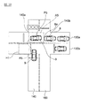
- the areas between the entrance boundary lines 35 and 135 of the branch road 30 and the rear end 8a of the preceding other vehicle 8 are designated as approach spaces A1 to A4, respectively.
- the entrance boundary lines 35 and 135 are branching portions between the branch road 30 and the traveling lane 40, and are boundaries that guide the vehicle entering the branch road 30 from the traveling lane 40 to the branch road 30.
- the approach space determination unit 16b determines whether or not the approach spaces A1 to A4 meet a predetermined condition set in advance.
- the predetermined condition means that, for example, the approach spaces A1 to A4 have the last section having a predetermined interval or more.
- the section between the rear end 8a of the other vehicle 8 which is the preceding vehicle lined up in the congested convoy of the branch road 30 and the entrance side lane end 36a of the branch road 30 is the last.
- the entrance-side lane end 36a of the branch road 30 refers to the entrance-side end of the region of the branch road 30 surrounded by a pair of boundaries 33 and 34 extending substantially parallel to each other.
- the "predetermined interval" is an interval in the lane direction of the branch road 30, and is an interval such that the own vehicle 9 can stop in a posture along the lane direction without tilting. ..
- the approach space determination unit 16b states that if the last section is shorter than the predetermined interval, "the last section of the predetermined interval or more". There is no "tail section", and it is determined that the approach spaces A1 to A4 meet the predetermined conditions.
- the approach spaces A1 and A2 do not have "the last sections of a predetermined interval or more". Therefore, it is determined that the approach spaces A1 and A2 meet the predetermined conditions.
- the target posture setting unit 18 shown in FIG. 3 sets the target posture of the own vehicle 9 at the target positions P1 to P4 at the end of the congested vehicle line based on the shapes of the approach spaces A1 to A4.
- the target posture is set as a posture in which the direction of the vehicle body of the own vehicle 9 is inclined at predetermined yaw angles ⁇ y1 to ⁇ y4 with respect to the lane direction of the branch road 30.
- the surrounding obstacle detection unit 17 includes the camera 4 and the radar device 5 as well as the surrounding condition detection unit 13, and detects obstacles around the own vehicle 9. Further, the target travel locus generation unit 19 generates target travel loci R1 to R4 based on information on the target posture, the target position, and surrounding obstacles of the own vehicle 9. Then, the route tracking control unit 20 controls the actuator 21 so that the own vehicle 9 travels following the target traveling loci R1 to R4.
- step S21 the congestion determination unit 14 of the travel control device 100 causes congestion in the branch road 30. Determine if it is.
- the branch road 30 is not congested, it is not necessary to set the target posture of the own vehicle 9, so the control ends.
- the control shifts to step S22, and the approach space determination unit 16b shows that the approach spaces A1 to A4 of the branch road 30 shown in FIGS. 5 to 8 meet the predetermined conditions.
- the approach space determination unit 16b determines that there is no trailing section of a predetermined interval or more between the entrance side lane ends 36a and 136a of the branch road 30 and the rear end 8a of the other vehicle 8.
- the approach spaces A1 to A4 meet the predetermined conditions.
- the branch road 30 has a trailing section of a predetermined interval or more, that is, when the approach space does not meet the predetermined condition, the own vehicle 9 does not tilt the vehicle body in a state of decelerating to a predetermined vehicle speed or less. Can fit in the approach space.
- the "state in which the own vehicle 9 has decelerated to a predetermined vehicle speed or less” includes a state in which the own vehicle 9 is temporarily stopped. Therefore, when the branch road 30 has a rearmost section having a predetermined interval or more and the approach space does not meet the predetermined condition, it is not necessary to set the target posture of the own vehicle 9, and the control ends.
- the travel control device 100 does not change the upper limit of the curvature of the own vehicle 9, maintains the upper limit of the curvature of the own vehicle 9 to a preset standard predetermined upper limit of the curvature, and keeps the own vehicle 9 Controls the behavior of the own vehicle 9 so that the vehicle travels in a straight posture along the lane direction of the branch road 30.
- the control shifts to step S23, and it is determined whether or not the inclination angle of the entrance boundary line of the branch road 30 is equal to or less than the predetermined threshold angle X. ..
- the entrance boundary lines 35 and 135 of the branch road 30 are the branch portions between the branch road 30 and the traveling lane 40, as shown in FIGS. 5 to 8, and the vehicle trying to enter the branch road 30 from the traveling lane 40. Is a boundary line that guides the vehicle to the branch road 30.
- the entrance boundary line 35 is inclined with respect to the lane direction of the branch road 30.
- the predetermined threshold angle X is, for example, 10 °.
- step S23 If it is determined in step S23 that the inclination angle of the entrance boundary line 35 of the branch road 30 is larger than the threshold angle X, control shifts to step S24, and the control proceeds along the branch road 30 to the opposite side of the traveling lane 40. It is determined whether or not the obstacle 50 as shown in FIG. 8 is provided.
- the obstacle 50 is, for example, a guardrail provided along the branch road 30, planting, or the like. If an obstacle 50 is provided along the branch road 30 on the opposite side of the traveling lane 40, the obstacle 50 is provided in front of the own vehicle 9 at the target position P4 at the end of the congested convoy. It will be in the state of being.
- step S24 when it is determined in step S24 that no obstacle is provided, the control shifts to step S26, and the target posture setting unit 18 targets the first target posture as shown in the examples of FIGS. 5 and 6. It is set as the target posture of the own vehicle 9 at the positions P1 and P2. Further, when it is determined in step S23 that the size of the inclination angle of the entrance boundary line 35 is equal to or less than the threshold angle X, the control shifts to step S25, and the target posture setting unit 18 is as shown in the example of FIG. The second target posture is set as the target posture of the own vehicle 9 at the target position P3.
- step S24 when it is determined in step S24 that the obstacle 50 is provided along the branch path 30, the control shifts to step S27, and the target posture setting unit 18 has a third target as shown in the example of FIG.
- the posture is set as the target posture of the own vehicle 9 at the target position P4.
- the first target posture, the second target posture, and the third target posture are target postures set based on different setting methods.
- step S28 the target travel locus generation unit 19 generates target travel loci R1 to R4 based on the target postures set in each of steps S25 to S27. Then, the path tracking control unit 20 raises the upper limit of the curvature of the own vehicle 9 in step S29, and controls the behavior of the own vehicle 9 according to the target traveling loci R1 to R4 in step S30.
- the upper limit of curvature is an upper limit value set to limit the curvature of the turning running of the own vehicle 9.
- the own vehicle 9 can travel along a target travel locus R1 to R4 different from the normal travel locus, and can take a target posture according to various yaw angles at target positions P1 to P4. become able to.
- the target travel loci R1 to R4 may be generated according to the target posture set based on the shapes of the approach spaces A1 to A4, respectively, or the travels simulated according to a plurality of curvatures. From the loci, loci that can realize the optimum target posture may be selected as the target traveling loci R1 to R4.
- the "optimal target posture" means, for example, that when the own vehicle 9 is in the approach spaces A1 to A4, the vehicle body does not protrude into the traveling lane 40, or the amount protruding into the traveling lane 40 is a predetermined amount or less. It means the attitude to become.
- the rearmost section L1 is shorter than a predetermined interval
- the approach space A1 meets a predetermined condition
- the inclination angle ⁇ 1 of the entrance boundary line 35 of the branch road 30 is a predetermined threshold angle. It is larger than X and no obstacle is provided along the branch road 30.
- the first target posture of the own vehicle 9 at the target position P1 behind the other vehicle 8 is a posture in which the direction of the vehicle body is inclined at a yaw angle ⁇ y1 with respect to the lane direction of the branch road 30.
- the target travel locus generation unit 19 of the travel control device 100 generates a target travel locus R1 from the current position of the own vehicle 9 to the target position P1.
- the route tracking control unit 20 raises the upper limit of the curvature of the own vehicle 9, and controls the behavior of the own vehicle 9 so that the own vehicle 9 follows the target traveling locus R1 and takes the first target posture at the target position P1.
- the target position P1 of the own vehicle 9 is set in the approach space A1.
- the rearmost section L2 is shorter than the predetermined interval, the approach space A2 meets the predetermined condition, and the inclination angle ⁇ 1 of the entrance boundary line 35 is predetermined, as in FIG. It is larger than the threshold angle X and no obstacle is provided along the branch path 30. Further, since the rearmost section L2 of the approach space A2 shown in FIG. 6 has a smaller interval than the last section L1 of the approach space A1 shown in FIG. 5, it is determined that the approach space A2 has a smaller space than the approach space A1. To. As shown in FIG.
- the yaw angle ⁇ y2 of the first target posture of the own vehicle 9 at the target position P2 becomes the same angle as the inclination angle ⁇ 1 of the entrance boundary line 35, and the first target The own vehicle 9 in the posture is inclined along the entrance boundary line 35. That is, when the first target posture is set for the own vehicle 9, the yaw angle of the first target posture of the own vehicle 9 changes according to the size of the approach spaces A1 and A2 of the branch road 30.
- the target travel locus generation unit 19 of the travel control device 100 generates the target travel locus R2 from the current position of the own vehicle 9 to the target position P2.
- the route tracking control unit 20 raises the upper limit of the curvature of the own vehicle 9, and controls the behavior of the own vehicle 9 so that the own vehicle 9 follows the target traveling locus R2 and takes the first target posture at the target position P2.
- the size of the approach spaces A1 and A2 may be judged not only by the length of the last sections L1 and L2 but also by the area or width of the approach spaces A1 and A2.
- the widths of the approach spaces A1 and A2 are the lengths of the approach spaces A1 and A2 in the direction perpendicular to the lane direction of the branch road 30, that is, in the width direction of the branch road 30.
- the travel control device 100 may determine the size of the approach spaces A1 and A2 based on the frontage lengths E1 and E2 of the approach spaces A1 and A2.
- the frontage lengths E1 and E2 of the approach spaces A1 and A2 are the lengths in the lane direction between the rear end 8a of the other vehicle 8 and the branch point 36b of the branch road 30. That is, the first target posture is set based on the shapes of the approach spaces A1 and A2.
- the shapes of the approach spaces A1 and A2 which are the criteria for setting the first target posture, include the areas and widths of the approach spaces A1 and A2, the intervals between the last sections L1 and L2, and the frontage lengths E1 and E2. Also includes the aspect ratio of the last sections L1 and L2 and the inclination angle ⁇ 1 of the entrance boundary line 35.
- the slope of the straight line connecting the start point and the end point of the entrance boundary line 35 is also included in the shapes of the entry spaces A1 and A2.
- FIG. 7 shows an example of the second target posture of the own vehicle 9.
- the approach space between the rear end 8a of the other vehicle 8 and the entrance boundary line 135 There is no last section in A3.
- the inclination angle ⁇ 2 of the entrance boundary line 135 of the branch path 30 is smaller than the predetermined threshold angle X.
- the target posture of the own vehicle 9 when temporarily stopping at the target position P3 behind the other vehicle 8 in the congested convoy is a posture in which the direction of the vehicle body is inclined at a yaw angle ⁇ y3 with respect to the lane direction of the branch road 30.
- the yaw angle ⁇ y3 of the target posture of the own vehicle 9 is set to be smaller than the inclination angle ⁇ 2 of the entrance boundary line 135.
- the target travel locus generation unit 19 of the travel control device 100 generates the target travel locus R3 from the current position of the own vehicle 9 to the target position P3.
- the route tracking control unit 20 controls the behavior of the own vehicle 9 so that the own vehicle 9 follows the target traveling locus R3 and takes the target posture at the target position P3.
- FIG. 8 shows an example of the third target posture of the own vehicle 9.
- the rearmost section L3 is shorter than a predetermined interval
- the inclination angle ⁇ 1 of the entrance boundary line 35 of the branch road 30 is larger than the predetermined threshold angle X
- the left side of the branch road 30 is larger than the predetermined threshold angle X
- An obstacle 50 is provided along the boundary 33 of the above.
- the obstacle 50 shall be a guardrail. Since the rearmost section L3 is shorter than the predetermined interval, the approach space A4 meets the predetermined condition.
- the target posture of the own vehicle 9 when temporarily stopping at the target position P4 behind the other vehicle 8 in the congested convoy is a posture in which the direction of the vehicle body is inclined at a yaw angle ⁇ y4 with respect to the lane direction of the branch road 30.
- the yaw angle ⁇ y4 of the third target posture is set to be smaller than the yaw angle when there is no obstacle 50 as shown in FIGS. 5 and 6. The higher the height of the obstacle 50, the smaller the yaw angle ⁇ y4 of the third target posture is set.
- the target travel locus generation unit 19 of the travel control device 100 generates the target travel locus R4 from the current position of the own vehicle 9 to the target position P4.
- the route tracking control unit 20 controls the behavior of the own vehicle 9 so that the own vehicle 9 follows the target traveling locus R4 and takes the target posture at the target position P4.
- the travel control device 100 when it is determined that there is a traffic jam in the branch road 30 adjacent to the travel lane 40, and the approach spaces A1 to A4 of the branch road 30 meet the predetermined conditions. In this case, the target posture of the own vehicle 9 at the target positions P1 to P4 behind the other vehicle 8 is set. As a result, the travel control device 100 can control the behavior of the own vehicle 9 according to various traffic congestion situations that may occur on the branch road 30.
- the travel control device 100 may fit in the approach spaces A1 to A4 in a state where the own vehicle 9 is decelerated below a predetermined vehicle speed without tilting the vehicle body. It is determined whether or not there is a trailing section that is longer than a predetermined interval that can be created. Then, when it is determined that the approach spaces A1 to A4 do not have the last section of the predetermined interval or more, the travel control device 100 determines that the approach spaces A1 to A4 meet the predetermined conditions. As a result, the travel control device 100 can set the optimum target posture of the own vehicle 9 at the target positions P1 to P4 even when the approach spaces A1 to A4 do not have a sufficient rearmost section.
- the own vehicle 9 can take a target posture in which the vehicle body is greatly tilted. It is possible to line up at the end of the congested convoy of the branch road 30 without protruding into the traveling lane 40.
- the travel control device 100 sets the target posture of the own vehicle 9 so that the larger the approach space A1, the closer the yaw angle ⁇ y1 is to 0 °. Set.
- the target posture of the own vehicle 9 can be set more appropriately according to the position of the other vehicle 8.
- the larger the approach space that is, the farther the position of the other vehicle 8 is, the closer the yaw angle of the target posture of the own vehicle 9 is to 0 °. Therefore, when the other vehicle 8 advances, the own vehicle 9 also It becomes possible to follow the other vehicle 8 and move along the branch road 30 more smoothly.
- the travel control device 100 enters.
- the target posture of the own vehicle 9 is set so that the yaw angle ⁇ y3 of the own vehicle 9 in the space A3 is smaller than the inclination angle ⁇ 2 of the entrance boundary line 135.
- the inclination angle ⁇ 2 of the entrance boundary line 135 of the branch road 30 is equal to or less than the threshold angle X
- the width of the approach space A3 at the target position P3 of the own vehicle 9 is narrow, and the inclination of the vehicle body of the own vehicle 9 is increased.
- the travel control device 100 sets the target posture of the own vehicle 9 so that the yaw angle ⁇ y3 of the own vehicle 9 is smaller than the inclination angle ⁇ 2 of the entrance boundary line 135, so that the vehicle body of the own vehicle 9 becomes excessively large. It prevents the vehicle from stopping behind the other vehicle 8 in an inclined posture, and minimizes the portion of the vehicle body of the own vehicle 9 that goes out to the traveling lane 40.
- the traveling control device 100 when the approach space A3 meets a predetermined condition and the inclination angle ⁇ 2 of the entrance boundary line 135 is equal to or less than the threshold angle X, the traveling control device 100 has a large approach space A3.
- the yaw angle ⁇ y3 of the own vehicle 9 is brought closer to 0 °.
- the travel control device 100 can reduce the portion of the vehicle body of the own vehicle 9 that may protrude into the traveling lane 40 as much as possible, and can adjust the target posture of the own vehicle 9 according to the position of the other vehicle 8. Can be set.
- the travel control device 100 has an obstacle.
- the target posture of the own vehicle 9 is set so that the yaw angle ⁇ y4 of the own vehicle 9 is smaller than when it is determined that the vehicle 9 is not provided.
- the own vehicle 9 is corrected to the obstacle.
- the occupants of the own vehicle 9 feel oppressive and anxious about the possibility of collision.
- the travel control device 100 sets the target posture so that the own vehicle 9 tilts at the target position P4, while suppressing an excessive tilting posture. Therefore, the feeling of oppression and anxiety felt by the occupants of the own vehicle 9 with respect to the obstacle 50 is reduced.
- the travel control device 100 sets the target posture so that the higher the height of the obstacle 50, the smaller the yaw angle ⁇ y4 of the own vehicle 9.
- the higher the height of the obstacle 50 provided in front the more easily the occupant of the own vehicle 9 feels oppressive to the obstacle 50.
- the yaw angle ⁇ y4 of the target posture of the own vehicle 9 is reduced, so that the feeling of oppression felt by the occupant of the own vehicle 9 can be reduced.
- the travel control device 100 sets the upper limit of the curvature of the own vehicle 9 higher than the preset predetermined upper limit of the curvature, and starts from the current position of the own vehicle 9.
- the target traveling loci R1 to R4 from the target positions P1 to P4 are generated.
- the own vehicle 9 travels along the target travel loci R1 to R4 different from the normal travel locus, and can take the target posture according to various yaw angles at the target positions P1 to P4. ..
- the travel control device 100 sets the approach space. It may be determined that A1 to A4 meet the predetermined conditions. Here, not only when the last sections L1 to L3 are shorter than the predetermined interval, but also when the area of the approach spaces A1 to A4 is less than or equal to the predetermined area or the width of the approach spaces A1 to A4 is less than or equal to the predetermined length. Even in this case, it is determined that "the own vehicle 9 cannot fit in the approach spaces A1 to A4 without tilting the vehicle body". As a result, the travel control device 100 can set various target postures of the own vehicle 9 in response to the case where the approach spaces A1 to A4 do not have sufficient space.
- the travel control device 100 when the own vehicle 9 travels based on the upper limit of the predetermined curvature and enters the approach spaces A1 to A4 in a state of decelerating to a predetermined vehicle speed or less, the vehicle body of the own vehicle 9 enters the traveling lane. It may be determined whether or not it is predicted that the amount exceeds a predetermined amount in 40. Then, the travel control device 100 determines that the approach spaces A1 to A4 meet the predetermined conditions when it is predicted that the vehicle body of the own vehicle protrudes into the traveling lane 40 by a predetermined amount or more. As a result, the travel control device 100 can set the target posture of the own vehicle 9 in advance so that the vehicle body of the own vehicle 9 does not protrude more than a predetermined amount into the traveling lane 40.
- Second Embodiment The vehicle travel control device 200 and the vehicle travelability control method using the vehicle travel control device 200 according to the second embodiment will be described with reference to FIGS. 9 to 12. Since the same reference numerals as those shown in FIGS. 1 to 8 indicate the same or similar configurations, detailed description thereof will be omitted.
- the travel control device 200 has another lane determination unit 112 in place of the branch determination unit 12 of the travel control device 100 according to the second embodiment.
- the other lane determination unit 112 determines whether or not there is a right turn lane 130a extending in the direction intersecting the traveling lane 140 in the planned traveling route calculated in advance (see FIGS. 10 to 12).
- the travel control device 200 has a turning travel region detection unit 118.
- the turning travel area detection unit 118 includes a camera 4 or a radar device 5.
- FIG. 10 shows an example in which the own vehicle 9 turns right at an intersection.
- the own vehicle 9 changes lanes from the current traveling lane 140 to the right turn lane 130a, which is another lane, across the left turn lane 130b.
- the right turn lane 130a and the left turn lane 130b are lanes extending in a direction intersecting the traveling lane 140.
- the approach space detection unit 16a of the travel control device 200 detects the approach space A5 in the right turn lane 130a.
- the approach space A5 is set as an area between the position of the left boundary line 140a of the traveling lane 140 and the rear end 8a of the other vehicle 8. That is, the shape of the approach space A5 changes depending on the position of the rear end 8a of the other vehicle 8.
- the approach space A5 has a length equal to or longer than a predetermined length in the lane direction of the right turn lane 130a, and the own vehicle 9 is in the approach space A5 of the target position P5 in the lane direction of the right turn lane 130a. You can line up in a straight line along the line.
- the approach space determination unit 16b determines whether or not the approach space A5 meets a predetermined condition set in advance.
- the predetermined condition in the example shown in FIG. 10 means that the rear end 8a of the other vehicle 8 that defines one end of the approach space A5 is behind the predetermined position.
- the predetermined position in this case is, for example, the position of the right boundary line 140b of the adjacent oncoming lane 160 of the traveling lane 140.
- the region of the left turn lane 130b required for the own vehicle 9 to swing its head and make a turning trip is defined as the turning running region H1.
- the turning traveling area detection unit 118 detects the turning traveling area H1 necessary for the own vehicle 9 to shake its head and make a turning traveling between the current position of the own vehicle 9 and the target position P5.
- the turning running area H1 since there is no other vehicle or obstacle in the turning running area H1, the turning running area H1 has sufficient space for the own vehicle 9 to shake its head and turn. It has a shape that can be secured.
- the target posture setting unit 18 sets the yaw angle of the target posture of the own vehicle 9 to 0 °. Then, the target traveling locus generation unit 19 takes a target traveling locus R5 from the current position of the own vehicle 9 to the target position P5 so that the own vehicle 9 takes a target posture along the lane direction of the right turn lane 130a at the target position P5. To generate.
- the route tracking control unit 20 raises the upper limit of the curvature of the own vehicle 9 and controls the behavior of the own vehicle 9 so that the own vehicle 9 follows the target traveling locus R5 and travels.
- the own vehicle 9 traveling along the target traveling locus R5 can enter the approach space A5 in the right turn lane 130a while shaking its head and making a sharp turn using the turning traveling region H1.
- FIG. 11 also shows an example in which the own vehicle 9 turns right at the intersection, as in FIG.
- the own vehicle 9 moves to the target position P6 behind the other vehicle 8 at the end of the congested convoy in the right turn lane 130a.
- the approach space detection unit 16a of the travel control device 200 detects the approach space A6 in the right turn lane 130a.
- the approach space determination unit 16b sets the approach space A6 to a predetermined condition. Judge that they do not match. Further, in the example shown in FIG. 11, the own vehicle 9 cannot fit in the approach space A6 unless the vehicle body is tilted.
- the target posture setting unit 18 sets the target posture of the own vehicle 9 as a posture tilted with respect to the lane direction of the right turn lane 130a.
- the yaw angle of the target posture of the own vehicle 9 is set as an angle equal to or less than the maximum angle that can be accommodated in the approach space A6.
- the target traveling locus generation unit 19 has a target traveling locus from the current position of the own vehicle 9 to the target position P6 so that the own vehicle 9 takes a target posture tilted with respect to the lane direction of the right turn lane 130a at the target position P6. Generate R6.
- the route tracking control unit 20 raises the upper limit of the curvature of the own vehicle 9 and controls the behavior of the own vehicle 9 so that the own vehicle 9 follows the target traveling locus R6.
- the own vehicle 9 traveling along the target traveling locus R6 can enter the approach space A6 in the right turn lane 130a while shaking its head and turning using the turning traveling region H2.
- the own vehicle 9 traveling along the target travel locus R6 makes a gentle turn compared to the own vehicle 9 traveling along the target travel locus R5 shown in FIG.
- FIG. 12 shows an example in which the own vehicle 9 turns right at a T-junction.
- the own vehicle 9 moves to the target position P7 or P8 behind the other vehicle 8 at the end of the congested convoy in the right turn lane 130a.
- a curb 150 is provided on the sidewalk side of the right turn lane 130a, and the surrounding obstacle detection unit 17 detects the curb 150 as an obstacle.
- the approach space detection unit 16a of the travel control device 200 detects the approach space A7 or A8 in the right turn lane 130a.
- the approach space A7 and the approach space A8 have different shapes based on the difference in the setting of the detection standard of the approach space by the approach space detection unit 16a.
- the approach space A7 is set as an area between the position of the boundary line 140c between the traveling lane 140 and the adjacent oncoming lane 160 and the rear end 8a of the other vehicle 8.
- the approach space A8 is set as an area between the position of the left boundary line 140a of the traveling lane 140 and the rear end 8a of the other vehicle 8. That is, the shape of the approach space differs depending on the difference in the detection criteria of the approach space.
- the approach space determination unit 16b determines that the approach space A7 or A8 is It is determined that the predetermined conditions are not met.
- the own vehicle 9 cannot fit in the approach space A7 unless the vehicle body is tilted, but the own vehicle 9 can fit in the approach space A8 in a straight posture along the lane direction of the right turn lane 130a.
- the turning traveling area detection unit 118 detects the turning traveling area H1 necessary for the own vehicle 9 to shake its head and make a turning run between the current position of the own vehicle 9 and the target position P7 or P8.
- the target posture setting unit 18 sets the target posture of the own vehicle 9 at the target position P7 with respect to the lane direction of the right turn lane 130a based on the shape of the approach space A7.
- the yaw angle of the target posture of the own vehicle 9 at the target position P7 is set so as to be as small as possible with respect to the curb 150 and smaller than the yaw angle of the target posture without the curb 150.
- the target travel locus generation unit 19 generates a target travel locus R7 from the current position of the own vehicle 9 to the target position P7.
- the route tracking control unit 20 raises the upper limit of the curvature of the own vehicle 9 and controls the behavior of the own vehicle 9 so that the own vehicle 9 follows the target travel locus R7.
- the route tracking control unit 20 raises the upper limit of the curvature of the own vehicle 9 and controls the behavior of the own vehicle 9 so that the own vehicle 9 follows the target travel locus R7.
- the target posture setting unit 18 sets the target posture of the own vehicle 9 at the target position P8 in the lane direction of the right turn lane 130a based on the shape of the approach space A8. Set as a posture that goes straight to.
- the yaw angle of the target posture of the own vehicle 9 at the target position P8 is set as 0 °.
- the target travel locus generation unit 19 generates a target travel locus R8 from the current position of the own vehicle 9 to the target position P8.
- the route tracking control unit 20 raises the upper limit of the curvature of the own vehicle 9 and controls the behavior of the own vehicle 9 so that the own vehicle 9 follows the target traveling locus R8. Therefore, the own vehicle 9 can enter the approach space A8 in the right turn lane 130a while shaking its head and turning using the turning travel area H1.
- the travel control device 200 is when it is determined that there is a traffic jam in the right turn lane 130a on the planned travel route, and when the approach spaces A5 to A8 of the right turn lane 130a meet the predetermined conditions. , Set the target posture of the own vehicle 9 at the target positions P5 to P8 behind the other vehicle 8. As a result, similarly to the travel control device 100 according to the first embodiment, the travel control device 200 controls the behavior of the own vehicle 9 according to various congestion situations that may occur in the right turn lane 130a of the lane change destination. Can be done.
- the other lane determination unit 112 of the travel control device 200 determines the lane extending in the direction intersecting the travel lane as another lane on the planned travel route. As a result, not only when the own vehicle 9 changes lanes to a branch road adjacent to the traveling lane 140, but also when the own vehicle 9 makes a right or left turn at an intersection or a T-junction, the own vehicle 9 responds to various traffic congestion situations. The behavior of the vehicle 9 can be controlled.
- the other lane determination unit 112 determines the right turn lane 130a as another lane on the planned traveling route, but the present invention is not limited to this, and when the own vehicle 9 turns left, the left turn lane 130b is changed. It may be determined as another lane on the planned travel route.
- the turning traveling area detection unit 118 detects the turning traveling areas H1 and H2 necessary for the own vehicle 9 to shake its head and make a turning run between the current position of the own vehicle 9 and the target positions P5 to P8. To do. Then, the target posture setting unit 18 and the target travel locus generation unit 19 are based on the shapes of the approach spaces A5 to A8 and the shapes of the turning travel regions H1 and H2, and the target posture and the target travel locus R5 at the target positions P5 to P8. ⁇ R8 is set.
- the traveling control device 200 has a more optimum target posture and target according to the road condition and the surrounding condition.
- the traveling locus R5 to R8 can be set.
- the travel control device 200 is provided with the curb.
- the target posture is set so that the yaw angle of the target posture of the own vehicle 9 is smaller than that in the case where the target posture is not set.
- the obstacle detected by the surrounding obstacle detection unit 17 is not limited to the curb 150, and may be a guardrail, a wall, or the like.
- the yaw angle of the target posture of the own vehicle 9 is 0 °. That is, the larger the approach space detected by the approach space detection unit 16a, the smaller the yaw angle of the target posture of the own vehicle 9. Therefore, when the curb 150 is provided at the boundary of the right turn lane 130a on the sidewalk side, the setting of the detection standard of the approach space may be appropriately changed in order to make the angle of the own vehicle 9 with respect to the curb 150 as small as possible.
- the travel control device 200 sets the upper limit of the curvature of the own vehicle 9 higher than the preset predetermined upper limit of curvature when the approach spaces A5 to A8 meet the predetermined conditions, similarly to the travel control device 100.
- the own vehicle 9 travels along the target travel locus R5 to R8 different from the normal travel locus, and can take the target posture according to various yaw angles at the target positions P5 to P8. ..
- the approach space determination unit 16b determines whether or not the approach spaces A5 to A8 meet the predetermined conditions based on the position of the rear end 8a of the other vehicle 8. Not limited. That is, when it is determined that there is a traffic jam in the right turn lane 130a, the approach space determination unit 16b determines whether or not the approach space determination unit 16b fits in the approach spaces A5 to A8 in a state where the own vehicle 9 is decelerated below a predetermined vehicle speed. If it is determined that the own vehicle 9 cannot fit in the approach spaces A5 to A8 without tilting the vehicle body, it may be determined that the approach spaces A5 to A8 meet the predetermined conditions.
- the branch road 30 and the right turn lane 130a correspond to other lanes according to the present invention. Further, the branch determination unit 12 corresponds to another lane determination unit according to the present invention.
Abstract
This travel control device: detects, if a determination was made that there is congestion in another lane on a planned travel route, an entry space existing at the rear of another vehicle within the other lane; determines whether the entry space meets a preset prescribed condition; sets, if the determination was that the entry space meets the prescribed condition, a target attitude of a host vehicle at a target position on the basis of the shape of the entry space; and generates a target travel trajectory from the current position of the host vehicle to the target position. The travel control device controls the behavior of the host vehicle such that the host vehicle travels by following the target travel trajectory.
Description
本発明は、自律走行可能な自車両の挙動を制御する車両の走行制御方法及び走行制御装置に関するものである。
The present invention relates to a vehicle travel control method and a travel control device that control the behavior of the own vehicle capable of autonomously traveling.
自車両の予定走行経路に分岐路等の他車線が存在する時、分岐路に渋滞が発生し、渋滞車列の最後尾が分岐路の入口付近まで来ている場合がある。特許文献1に記載される走行制御装置は、渋滞車列の車両が分岐路入口から隣接車線に溢れている時には、自車両の路外逸脱抑制制御を緩和し、自車両を路肩に寄せて渋滞車列の後ろに付けるように制御する。
When there is another lane such as a branch road in the planned travel route of the own vehicle, congestion may occur on the branch road and the end of the congested convoy may come near the entrance of the branch road. The travel control device described in Patent Document 1 relaxes the off-road deviation suppression control of the own vehicle when the vehicle in the congested convoy overflows from the entrance of the branch road to the adjacent lane, and brings the own vehicle closer to the shoulder to cause congestion. Control so that it is attached to the back of the train.
しかしながら、特許文献1では、渋滞車列が分岐路入口から溢れている場合は想定されているが、分岐路で起こり得る様々な渋滞の状況については想定されていない。例えば、特許文献1では、渋滞車列の最後尾が分岐路入口から溢れてはいないものの、自車両が分岐路に進入できるスペースが小さく、最後尾位置で車体の一部が隣接する走行車線にはみ出してしまう場合や、車体の向きを傾けなければ分岐路に進入することができない場合等については考慮されていない。従って、自車両が車線変更を行う場合、車線変更先の他車線の実際の渋滞の状況にあった適切な走行ができないおそれがあった。
However, in Patent Document 1, it is assumed that the congested convoy overflows from the entrance of the branch road, but it is not assumed that various traffic jam situations may occur at the branch road. For example, in Patent Document 1, although the tail end of the congested convoy does not overflow from the branch road entrance, the space where the own vehicle can enter the branch road is small, and a part of the vehicle body is in the adjacent traveling lane at the tail end position. It is not taken into consideration when the vehicle sticks out or when the vehicle cannot enter the branch road without tilting the direction of the vehicle. Therefore, when the own vehicle changes lanes, there is a risk that the vehicle cannot travel properly according to the actual traffic congestion in the other lane to which the lane is changed.
本発明が解決しようとする課題は、車線変更先の他車線で起こり得る様々な渋滞の状況に合わせて自車両の挙動を制御することができる車両の走行制御方法及び走行制御装置を提供することである。
An object to be solved by the present invention is to provide a vehicle travel control method and a travel control device capable of controlling the behavior of the own vehicle according to various traffic congestion situations that may occur in another lane to which the lane is changed. Is.
本発明は、予定走行経路上の他車線に渋滞が有ると判定された場合に、他車線内の他車両の後方に存在する進入スペースを検出し、進入スペースが所定条件に合致すると判定した場合に、目標位置における自車両の目標姿勢を、進入スペースの形状に基づいて設定することによって、上記課題を解決する。
The present invention detects an approach space existing behind another vehicle in the other lane when it is determined that there is congestion in another lane on the planned travel route, and determines that the approach space meets a predetermined condition. In addition, the above problem is solved by setting the target posture of the own vehicle at the target position based on the shape of the approach space.
本発明によれば、予定走行経路上の他車線への進入スペースの条件に応じて、他車線の渋滞車列の後ろに並ぶ自車両の目標姿勢を設定するため、車線変更先の他車線で起こり得る様々な渋滞の状況に合わせて自車両の挙動を制御することができる。
According to the present invention, in order to set the target posture of the own vehicle lined up behind the congested lane of the other lane according to the condition of the approach space to the other lane on the planned traveling route, the target lane of the own vehicle is set in the other lane of the lane change destination. It is possible to control the behavior of the own vehicle according to various possible traffic conditions.
以下、本発明の実施形態を図面に基づいて説明する。
《第1実施形態》
第1実施形態に係る車両の走行制御装置100及び走行制御装置100を用いた車両の走行性制御方法について、図1~8を用いて説明する。
図1は、走行制御装置100を含む走行制御システム101の構成を示すブロック図である。なお、本発明に係る車両の走行制御方法及び車両の走行制御装置100は、自律的に走行する自車両9の周囲の状況に基づいて、自車両9のアクチュエータ21の挙動をコンピュータによって支援するための走行制御方法及び走行制御装置である。 Hereinafter, embodiments of the present invention will be described with reference to the drawings.
<< First Embodiment >>
The vehicletravel control device 100 and the vehicle travelability control method using the vehicle travel control device 100 according to the first embodiment will be described with reference to FIGS. 1 to 8.
FIG. 1 is a block diagram showing a configuration of a travel control system 101 including atravel control device 100. The vehicle travel control method and the vehicle travel control device 100 according to the present invention support the behavior of the actuator 21 of the own vehicle 9 by a computer based on the surrounding conditions of the own vehicle 9 that autonomously travels. It is a running control method and a running control device.
《第1実施形態》
第1実施形態に係る車両の走行制御装置100及び走行制御装置100を用いた車両の走行性制御方法について、図1~8を用いて説明する。
図1は、走行制御装置100を含む走行制御システム101の構成を示すブロック図である。なお、本発明に係る車両の走行制御方法及び車両の走行制御装置100は、自律的に走行する自車両9の周囲の状況に基づいて、自車両9のアクチュエータ21の挙動をコンピュータによって支援するための走行制御方法及び走行制御装置である。 Hereinafter, embodiments of the present invention will be described with reference to the drawings.
<< First Embodiment >>
The vehicle
FIG. 1 is a block diagram showing a configuration of a travel control system 101 including a
走行制御装置100は、一又は複数のコンピュータ及び当該コンピュータにインストールされたソフトウェアにより構成される。走行制御装置100は、自車両9を自律的に走行させるための自動運転制御を実行するためのプログラムを格納したROMと、このROMに格納されたプログラムを実行するCPUと、アクセス可能な記憶装置として機能するRAMとから構成される。なお、動作回路としては、CPUに代えて又はこれとともに、MPU、DSP、ASIC、FPGA等を用いることができる。
The travel control device 100 is composed of one or more computers and software installed on the computers. The travel control device 100 includes a ROM that stores a program for executing automatic driving control for autonomously traveling the own vehicle 9, a CPU that executes the program stored in the ROM, and an accessible storage device. It consists of a RAM that functions as. As the operating circuit, MPU, DSP, ASIC, FPGA or the like can be used instead of or in combination with the CPU.
走行制御装置100は、ナビゲーション装置1、地図データベース2、自車両位置検出器3、カメラ4、レーダー装置5、車速センサ6及び入力部7からの情報に基づき、現在地から目的地までの自車両9の目標走行軌跡を演算して決定する。走行制御装置100によって決定された目標走行軌跡は、1つ以上の車線、直線状のライン、曲率を有するカーブ若しくは進行方向を含む進路、又はこれらの組み合わせを含むデータとして出力される。さらに、走行制御装置100は、目標走行軌跡の情報に基づき、自車両9に対して出力すべき制御指令値Fを、所定の時間間隔で演算して出力する。走行制御装置100は、制御指令値Fに基づいて自車両9のアクチュエータ21の挙動を制御する。
The travel control device 100 is a vehicle 9 from the current location to the destination based on information from the navigation device 1, the map database 2, the vehicle position detector 3, the camera 4, the radar device 5, the vehicle speed sensor 6, and the input unit 7. The target travel locus of is calculated and determined. The target travel locus determined by the travel control device 100 is output as data including one or more lanes, a straight line, a course including a curve having a curvature or a traveling direction, or a combination thereof. Further, the travel control device 100 calculates and outputs the control command value F to be output to the own vehicle 9 at predetermined time intervals based on the information of the target travel locus. The travel control device 100 controls the behavior of the actuator 21 of the own vehicle 9 based on the control command value F.
ナビゲーション装置1は、自車両9の現在位置に関する情報や目的地までの走行ルート等の情報を表示可能なディスプレイと、入力された目的地及び自車両位置検出器3により検出された現在地から、選択された経路演算モードに応じた走行経路を演算するプログラムが実装されたコンピュータとを備える。
The navigation device 1 selects from a display capable of displaying information on the current position of the own vehicle 9 and information such as a travel route to the destination, and the input destination and the current location detected by the own vehicle position detector 3. It is provided with a computer equipped with a program that calculates a traveling route according to the route calculation mode.
地図データベース2には、データ取得用車両を用いて実際の道路を走行した際に検出された道路形状に基づく三次元高精細地図情報が格納されている。この地図データベース2が記憶する三次元高精細地図情報には、地図情報とともに、各地図座標における境界情報、二次元位置情報、三次元位置情報、道路情報、道路属性情報、上り情報、下り情報、レーン識別情報、接続先レーン情報等が含まれている。道路情報及び道路属性には、道路幅、曲率半径、路肩構造物、道路交通法規(制限速度、車線変更の可否)、道路の合流地点、分岐地点、料金所、車線数の減少位置、サービスエリア/パーキングエリア等の情報が含まれている。
The map database 2 stores three-dimensional high-definition map information based on the road shape detected when traveling on an actual road using a data acquisition vehicle. The three-dimensional high-definition map information stored in this map database 2 includes map information, boundary information at each map coordinate, two-dimensional position information, three-dimensional position information, road information, road attribute information, ascending information, descending information, and so on. Lane identification information, connection destination lane information, etc. are included. Road information and road attributes include road width, radius of curvature, shoulder structure, road traffic regulations (speed limit, lane changeability), road confluences, branch points, toll gates, lane reduction positions, service areas. / Contains information such as parking areas.
自車両位置検出器3は、GPSユニット、ジャイロセンサ、及び車速センサ等から構成される。自車両位置検出器3は、GPSユニットにより複数の衛星通信から送信される電波を検出し、自車両9の位置情報を周期的に取得するとともに、取得した自車両9の位置情報と、ジャイロセンサから取得した角度変化情報と、車速センサから取得した車速とに基づいて、自車両9の現在の位置情報を周期的に検出する。
The own vehicle position detector 3 is composed of a GPS unit, a gyro sensor, a vehicle speed sensor, and the like. The own vehicle position detector 3 detects radio waves transmitted from a plurality of satellite communications by the GPS unit, periodically acquires the position information of the own vehicle 9, and also acquires the acquired position information of the own vehicle 9 and a gyro sensor. The current position information of the own vehicle 9 is periodically detected based on the angle change information acquired from and the vehicle speed acquired from the vehicle speed sensor.
カメラ4は、CCD広角カメラ等のイメージセンサからなり、自車両9に前方、後方及び必要に応じて両側方に設けられ、自車両9の周囲を撮像して画像情報を取得する。カメラ4は、ステレオカメラや全方位カメラであってもよく、複数のイメージセンサを含むようにしてもよい。カメラ4は、取得した画像データから、自車両9の前方に存在する道路及び道路周辺の構造物、道路標示、標識、他車両、二輪車、自転車、歩行者等を自車両9の周囲状況として検出する。
The camera 4 is composed of an image sensor such as a CCD wide-angle camera, and is provided in the front and rear of the own vehicle 9 and on both sides as needed, and acquires image information by photographing the surroundings of the own vehicle 9. The camera 4 may be a stereo camera or an omnidirectional camera, and may include a plurality of image sensors. From the acquired image data, the camera 4 detects the road and structures around the road, road signs, signs, other vehicles, two-wheeled vehicles, bicycles, pedestrians, etc. in front of the own vehicle 9 as the surrounding conditions of the own vehicle 9. To do.
レーダー装置5は、自車両9の前方、後方及び両側方に設けられ、ミリ波又は超音波を自車両9の周囲に照射して自車両9の周囲の所定範囲を走査し、自車両9の周囲に存在する他車両、二輪車、自転車、歩行者、路肩の縁石、ガードレール、壁面、盛り土等の障害物を検出する。例えば、レーダー装置5は、障害物と自車両9との相対位置(方位)、障害物の相対速度、自車両9から障害物までの距離等を自車両9の周囲状況として検出する。
The radar device 5 is provided on the front, rear, and both sides of the own vehicle 9, irradiates the periphery of the own vehicle 9 with millimeter waves or ultrasonic waves, scans a predetermined range around the own vehicle 9, and scans the predetermined range around the own vehicle 9. Detects obstacles such as other vehicles, two-wheeled vehicles, bicycles, pedestrians, curbs on the shoulder, guardrails, walls, and fillings that exist in the surrounding area. For example, the radar device 5 detects the relative position (direction) between the obstacle and the own vehicle 9, the relative speed of the obstacle, the distance from the own vehicle 9 to the obstacle, and the like as the surrounding conditions of the own vehicle 9.
車速センサ6は、ドライブシャフト等の自車両9の駆動系アクチュエータの回転速度を計測し、これに基づいて自車両9の走行速度を検出する。入力部7は、機械的スイッチや、ディスプレイに表示された電子的スイッチ等から構成され、ドライバによって、目的地等の情報及び自動運転を行うか否かの決定が入力される。
The vehicle speed sensor 6 measures the rotation speed of the drive system actuator of the own vehicle 9 such as a drive shaft, and detects the traveling speed of the own vehicle 9 based on this. The input unit 7 is composed of a mechanical switch, an electronic switch displayed on the display, and the like, and the driver inputs information such as a destination and a decision as to whether or not to perform automatic operation.
次に、走行制御装置100による全体的な制御の概要について、図2を用いて説明する。
まず、走行制御装置100は、自車両位置検出器3によって得られた自車両9の位置情報及び地図データベース2の地図情報により、自己位置の推定を行う(ステップS1)。また、走行制御装置100は、カメラ4及びレーダー装置5によって、自車両9の周囲の歩行者その他の障害物を認識する(ステップS2)。そして、ステップS1で推定された自己位置の情報と、ステップS2で認識された障害物等の情報とが、地図データベース2の地図上に展開されて表示される(ステップS3)。 Next, an outline of the overall control by thetravel control device 100 will be described with reference to FIG.
First, thetravel control device 100 estimates its own position based on the position information of its own vehicle 9 obtained by the own vehicle position detector 3 and the map information of the map database 2 (step S1). Further, the travel control device 100 recognizes pedestrians and other obstacles around the own vehicle 9 by the camera 4 and the radar device 5 (step S2). Then, the self-position information estimated in step S1 and the information such as obstacles recognized in step S2 are expanded and displayed on the map of the map database 2 (step S3).
まず、走行制御装置100は、自車両位置検出器3によって得られた自車両9の位置情報及び地図データベース2の地図情報により、自己位置の推定を行う(ステップS1)。また、走行制御装置100は、カメラ4及びレーダー装置5によって、自車両9の周囲の歩行者その他の障害物を認識する(ステップS2)。そして、ステップS1で推定された自己位置の情報と、ステップS2で認識された障害物等の情報とが、地図データベース2の地図上に展開されて表示される(ステップS3)。 Next, an outline of the overall control by the
First, the
さらに、入力部7から目的地が入力され、自律走行制御の開始指示が入力されると、地図データベース2の地図上に目的地が設定され(ステップS4)、ナビゲーション装置1及び地図データベース2を用いて、現在地から目的地までのルートプランニングがなされる(ステップS5)。そして、地図上に展開された情報に基づいて、自車両9の行動が決定される(ステップS6)。具体的には、たとえばプラニングされたルートに存在する複数の交差点の各位置において、自車両9がどの方向に曲がるか等が決定される。そして次に、カメラ4又はレーダー装置5により認識された障害物等の情報に基づき、地図データベース2の地図上において、ドライブゾーンプランニングが行われる(ステップS7)。具体的には、障害物との関係を考慮すると、ルート上の所定位置又は所定間隔において、自車両9がどの車線を走行するべきか等が適宜設定される。そして、走行制御装置100は、入力された現在地及び目的地の位置情報、設定されたルート情報、自車両9の行動及びドライブゾーンの情報に基づいて、自車両9の目標走行軌跡を設定する(ステップS8)。さらに、走行制御装置100は、目標走行軌跡に自車両9が追従するように、自車両9の挙動を制御する(ステップS9)。
Further, when the destination is input from the input unit 7 and the start instruction of the autonomous driving control is input, the destination is set on the map of the map database 2 (step S4), and the navigation device 1 and the map database 2 are used. Then, route planning from the current location to the destination is performed (step S5). Then, the action of the own vehicle 9 is determined based on the information developed on the map (step S6). Specifically, for example, at each position of a plurality of intersections existing on the planned route, the direction in which the own vehicle 9 turns is determined. Next, drive zone planning is performed on the map of the map database 2 based on the information of obstacles and the like recognized by the camera 4 or the radar device 5 (step S7). Specifically, in consideration of the relationship with obstacles, which lane the own vehicle 9 should travel in at a predetermined position or a predetermined interval on the route is appropriately set. Then, the travel control device 100 sets the target travel locus of the own vehicle 9 based on the input position information of the current location and the destination, the set route information, the behavior of the own vehicle 9, and the drive zone information ( Step S8). Further, the travel control device 100 controls the behavior of the own vehicle 9 so that the own vehicle 9 follows the target travel locus (step S9).
次に、図3に示す走行制御装置100の構成に基づいて、渋滞時の分岐路における自車両9の挙動の制御の手順を説明する。走行制御装置100は、車線計画部10、走路境界取得部11、分岐判定部12、周囲状況検出部13、渋滞判定部14、走路境界選択部15、進入スペース検出部16a、進入スペース判定部16b、周囲障害物検出部17、目標姿勢設定部18、目標走行軌跡生成部19及び経路追従制御部20を有する。
Next, a procedure for controlling the behavior of the own vehicle 9 on the branch road during a traffic jam will be described based on the configuration of the travel control device 100 shown in FIG. The travel control device 100 includes a lane planning unit 10, a track boundary acquisition unit 11, a branch determination unit 12, a surrounding condition detection unit 13, a traffic jam determination unit 14, a track boundary selection unit 15, an approach space detection unit 16a, and an approach space determination unit 16b. , Around obstacle detection unit 17, target posture setting unit 18, target travel locus generation unit 19, and route tracking control unit 20.
まず、走行制御装置100の車線計画部10は、図2のステップS7のドライブゾーンプランニングに基づき、自車両9の車線計画を設定する。走路境界取得部11は、この車線計画に基づき、自車両9が走行すべき予定走行経路の各車線の境界を取得する。分岐判定部12は、自車両9の予定走行経路に分岐路が有るか否かを判定する。なお、分岐判定部12は、他車線判定部を構成する。
First, the lane planning unit 10 of the travel control device 100 sets the lane plan of the own vehicle 9 based on the drive zone planning in step S7 of FIG. Based on this lane plan, the lane boundary acquisition unit 11 acquires the boundary of each lane of the planned travel route on which the own vehicle 9 should travel. The branch determination unit 12 determines whether or not there is a branch path in the planned travel route of the own vehicle 9. The branch determination unit 12 constitutes another lane determination unit.
周囲状況検出部13は、カメラ4及びレーダー装置5を含み、自車両9の周囲の状況及び他車両の存在を検出する。渋滞判定部14は、自車両9の予定走行経路に分岐路が有ると判定された場合に、自車両9の周囲の他車両の存在又は受信した渋滞情報に基づいて、分岐路に渋滞が発生しているか否かを判定する。走路境界選択部15は、走路境界取得部11によって取得された予定走行経路の各車線の境界と、渋滞判定部14によって判定された分岐路の渋滞状況とに基づいて、最終的に自車両9が走行する車線を選択する。
The surrounding situation detection unit 13 includes the camera 4 and the radar device 5, and detects the surrounding situation of the own vehicle 9 and the presence of other vehicles. When the congestion determination unit 14 determines that the planned traveling route of the own vehicle 9 has a branch road, the congestion on the branch road occurs based on the existence of other vehicles around the own vehicle 9 or the received congestion information. Determine if it is. The track boundary selection unit 15 finally owns the vehicle 9 based on the boundary of each lane of the planned travel route acquired by the track boundary acquisition unit 11 and the congestion state of the branch road determined by the congestion determination unit 14. Select the lane in which you will drive.
進入スペース検出部16aは、走路境界選択部15によって選択された予定走行経路の各車線の境界の形状に基づいて、分岐路の進入スペースを検出する。進入スペースとは、車線変更先の他車線内で自車両9に先行する他車両の後方に存在するスペースであり、自車両9は、進入スペースを介して他車線に進入することができる。例えば、図5~8に示す例では、各々、分岐路30の入口境界線35,135と先行する他車両8の後端8aとの間の領域を進入スペースA1~A4とする。なお、入口境界線35,135とは、分岐路30と走行車線40との分岐部で、走行車線40から分岐路30に入ろうとしている車両を分岐路30に案内する境界線である。また、進入スペース判定部16bは、進入スペースA1~A4が予め設定した所定条件に合致するか否かを判定する。
The approach space detection unit 16a detects the approach space of the branch road based on the shape of the boundary of each lane of the planned travel route selected by the track boundary selection unit 15. The approach space is a space existing behind the other vehicle preceding the own vehicle 9 in the other lane of the lane change destination, and the own vehicle 9 can enter the other lane through the approach space. For example, in the examples shown in FIGS. 5 to 8, the areas between the entrance boundary lines 35 and 135 of the branch road 30 and the rear end 8a of the preceding other vehicle 8 are designated as approach spaces A1 to A4, respectively. The entrance boundary lines 35 and 135 are branching portions between the branch road 30 and the traveling lane 40, and are boundaries that guide the vehicle entering the branch road 30 from the traveling lane 40 to the branch road 30. Further, the approach space determination unit 16b determines whether or not the approach spaces A1 to A4 meet a predetermined condition set in advance.
ここで、所定条件とは、例えば、進入スペースA1~A4に、所定の間隔以上の最後尾区間が有ることをいう。図5及び6に示す例では、分岐路30の渋滞車列に並んでいる先行車である他車両8の後端8aと分岐路30の入口側車線端部36aとの間の区間が最後尾区間L1,L2である。ここで、分岐路30の入口側車線端部36aとは、互いにほぼ平行に延びる一対の境界33,34に囲まれた分岐路30の領域の入口側の端部をいう。また、この実施形態において「所定の間隔」とは、分岐路30の車線方向の間隔であり、自車両9が車線方向に沿った姿勢で傾かずに停車することが可能な程度の間隔である。
Here, the predetermined condition means that, for example, the approach spaces A1 to A4 have the last section having a predetermined interval or more. In the examples shown in FIGS. 5 and 6, the section between the rear end 8a of the other vehicle 8 which is the preceding vehicle lined up in the congested convoy of the branch road 30 and the entrance side lane end 36a of the branch road 30 is the last. The sections L1 and L2. Here, the entrance-side lane end 36a of the branch road 30 refers to the entrance-side end of the region of the branch road 30 surrounded by a pair of boundaries 33 and 34 extending substantially parallel to each other. Further, in this embodiment, the "predetermined interval" is an interval in the lane direction of the branch road 30, and is an interval such that the own vehicle 9 can stop in a posture along the lane direction without tilting. ..
なお、進入スペース判定部16bは、分岐路30の進入スペースA1~A4に最後尾区間が有る場合であっても、最後尾区間が所定の間隔よりも短い場合は、「所定の間隔以上の最後尾区間」は無く、進入スペースA1~A4は所定条件に合致するものと判定する。図5及び6に示す例では、最後尾区間L1,L2の長さは自車両9の全長よりも短いため、進入スペースA1,A2には「所定の間隔以上の最後尾区間」は無い。従って、進入スペースA1,A2は所定条件に合致すると判定される。
In addition, even if the approach space A1 to A4 of the branch road 30 has the last section, the approach space determination unit 16b states that if the last section is shorter than the predetermined interval, "the last section of the predetermined interval or more". There is no "tail section", and it is determined that the approach spaces A1 to A4 meet the predetermined conditions. In the examples shown in FIGS. 5 and 6, since the lengths of the rearmost sections L1 and L2 are shorter than the total length of the own vehicle 9, the approach spaces A1 and A2 do not have "the last sections of a predetermined interval or more". Therefore, it is determined that the approach spaces A1 and A2 meet the predetermined conditions.
さらに、図3に示す目標姿勢設定部18は、進入スペースA1~A4の形状に基づいて、渋滞車列の最後尾の目標位置P1~P4における自車両9の目標姿勢を設定する。目標姿勢は、分岐路30の車線方向に対して所定のヨー角θy1~θy4で自車両9の車体の向きが傾斜する姿勢として設定される。
Further, the target posture setting unit 18 shown in FIG. 3 sets the target posture of the own vehicle 9 at the target positions P1 to P4 at the end of the congested vehicle line based on the shapes of the approach spaces A1 to A4. The target posture is set as a posture in which the direction of the vehicle body of the own vehicle 9 is inclined at predetermined yaw angles θy1 to θy4 with respect to the lane direction of the branch road 30.
また、周囲障害物検出部17は、周囲状況検出部13と同様に、カメラ4及びレーダー装置5を含み、自車両9の周囲の障害物を検出する。また、目標走行軌跡生成部19は、自車両9の目標姿勢、目標位置及び周囲障害物の情報に基づいて、目標走行軌跡R1~R4を生成する。そして、経路追従制御部20は、自車両9が目標走行軌跡R1~R4に追従して走行するように、アクチュエータ21を制御する。
Further, the surrounding obstacle detection unit 17 includes the camera 4 and the radar device 5 as well as the surrounding condition detection unit 13, and detects obstacles around the own vehicle 9. Further, the target travel locus generation unit 19 generates target travel loci R1 to R4 based on information on the target posture, the target position, and surrounding obstacles of the own vehicle 9. Then, the route tracking control unit 20 controls the actuator 21 so that the own vehicle 9 travels following the target traveling loci R1 to R4.
次に、目標姿勢設定部18による自車両9の目標姿勢の設定方法について、図4~8を参照して、さらに詳細に説明する。
図5~8に示すように予定走行経路に分岐路30が有る場合、まず、図4に示すように、ステップS21において、走行制御装置100の渋滞判定部14は、分岐路30に渋滞が発生しているか否かを判定する。ここで、分岐路30が渋滞していない場合は、自車両9の目標姿勢の設定は不要であるため、制御は終了する。 Next, a method of setting the target posture of theown vehicle 9 by the target posture setting unit 18 will be described in more detail with reference to FIGS. 4 to 8.
When there is abranch road 30 in the planned travel route as shown in FIGS. 5 to 8, first, as shown in FIG. 4, in step S21, the congestion determination unit 14 of the travel control device 100 causes congestion in the branch road 30. Determine if it is. Here, when the branch road 30 is not congested, it is not necessary to set the target posture of the own vehicle 9, so the control ends.
図5~8に示すように予定走行経路に分岐路30が有る場合、まず、図4に示すように、ステップS21において、走行制御装置100の渋滞判定部14は、分岐路30に渋滞が発生しているか否かを判定する。ここで、分岐路30が渋滞していない場合は、自車両9の目標姿勢の設定は不要であるため、制御は終了する。 Next, a method of setting the target posture of the
When there is a
次に、分岐路30に渋滞が発生している場合、制御はステップS22に移り、進入スペース判定部16bは、図5~8に示す分岐路30の進入スペースA1~A4が所定条件に合致するか否かを判定する。具体的には、進入スペース判定部16bは、分岐路30の入口側車線端部36a,136aから他車両8の後端8aまでの間で、所定の間隔以上の最後尾区間が無い場合を「進入スペースA1~A4が所定条件に合致する」と判定する。ここで、分岐路30に所定の間隔以上の最後尾区間が有る時、すなわち、進入スペースが所定条件に合致しない場合、自車両9は所定の車速以下に減速した状態で車体を傾斜させずに進入スペースに収まることができる。なお、「自車両9が所定の車速以下に減速した状態」には、自車両9が一時停止している状態も含まれる。従って、分岐路30に所定の間隔以上の最後尾区間が有り、進入スペースが所定条件に合致しない時は、自車両9の目標姿勢の設定は不要であるため、制御は終了する。具体的には、進入スペースが所定条件に合致しない場合は、走行制御装置100は、自車両9の曲率上限を変更せず、予め設定された標準的な規定曲率上限に維持し、自車両9が分岐路30の車線方向に沿って真っ直ぐな姿勢で走行するように自車両9の挙動を制御する。
Next, when the branch road 30 is congested, the control shifts to step S22, and the approach space determination unit 16b shows that the approach spaces A1 to A4 of the branch road 30 shown in FIGS. 5 to 8 meet the predetermined conditions. Judge whether or not. Specifically, the approach space determination unit 16b determines that there is no trailing section of a predetermined interval or more between the entrance side lane ends 36a and 136a of the branch road 30 and the rear end 8a of the other vehicle 8. The approach spaces A1 to A4 meet the predetermined conditions. " Here, when the branch road 30 has a trailing section of a predetermined interval or more, that is, when the approach space does not meet the predetermined condition, the own vehicle 9 does not tilt the vehicle body in a state of decelerating to a predetermined vehicle speed or less. Can fit in the approach space. The "state in which the own vehicle 9 has decelerated to a predetermined vehicle speed or less" includes a state in which the own vehicle 9 is temporarily stopped. Therefore, when the branch road 30 has a rearmost section having a predetermined interval or more and the approach space does not meet the predetermined condition, it is not necessary to set the target posture of the own vehicle 9, and the control ends. Specifically, when the approach space does not meet the predetermined conditions, the travel control device 100 does not change the upper limit of the curvature of the own vehicle 9, maintains the upper limit of the curvature of the own vehicle 9 to a preset standard predetermined upper limit of the curvature, and keeps the own vehicle 9 Controls the behavior of the own vehicle 9 so that the vehicle travels in a straight posture along the lane direction of the branch road 30.
次に、分岐路30の進入スペースA1~A4が所定条件に合致する場合、制御はステップS23に移り、分岐路30の入口境界線の傾斜角が所定の閾値角度X以下か否かを判定する。ここで、分岐路30の入口境界線35,135とは、図5~8に示すように、分岐路30と走行車線40との分岐部で、走行車線40から分岐路30に入ろうとしている車両を分岐路30に案内する境界線である。入口境界線35は、分岐路30の車線方向に対して傾斜している。なお、所定の閾値角度Xは、例えば、10°である。
Next, when the approach spaces A1 to A4 of the branch road 30 meet the predetermined conditions, the control shifts to step S23, and it is determined whether or not the inclination angle of the entrance boundary line of the branch road 30 is equal to or less than the predetermined threshold angle X. .. Here, the entrance boundary lines 35 and 135 of the branch road 30 are the branch portions between the branch road 30 and the traveling lane 40, as shown in FIGS. 5 to 8, and the vehicle trying to enter the branch road 30 from the traveling lane 40. Is a boundary line that guides the vehicle to the branch road 30. The entrance boundary line 35 is inclined with respect to the lane direction of the branch road 30. The predetermined threshold angle X is, for example, 10 °.
ステップS23で、分岐路30の入口境界線35の傾斜角が閾値角度Xよりも大きいと判定された場合、制御はステップS24に移り、分岐路30に沿って走行車線40とは反対側に、図8に示すような障害物50が設けられているか否かが判定される。障害物50は、例えば、分岐路30に沿って設けられるガードレール、植栽等である。なお、分岐路30に沿って走行車線40とは反対側に障害物50が設けられている場合は、渋滞車列の最後尾の目標位置P4において自車両9の前方に障害物50が設けられている状態となる。
If it is determined in step S23 that the inclination angle of the entrance boundary line 35 of the branch road 30 is larger than the threshold angle X, control shifts to step S24, and the control proceeds along the branch road 30 to the opposite side of the traveling lane 40. It is determined whether or not the obstacle 50 as shown in FIG. 8 is provided. The obstacle 50 is, for example, a guardrail provided along the branch road 30, planting, or the like. If an obstacle 50 is provided along the branch road 30 on the opposite side of the traveling lane 40, the obstacle 50 is provided in front of the own vehicle 9 at the target position P4 at the end of the congested convoy. It will be in the state of being.
そして、ステップS24で、障害物が設けられていないと判定された場合、制御はステップS26に移り、目標姿勢設定部18は、図5及び6の例に示すような第1目標姿勢を、目標位置P1,P2での自車両9の目標姿勢として設定する。また、ステップS23で、入口境界線35の傾斜角の大きさが閾値角度X以下であると判定された場合、制御はステップS25に移り、目標姿勢設定部18は、図7の例に示すような第2目標姿勢を、目標位置P3での自車両9の目標姿勢として設定する。さらに、ステップS24で、分岐路30に沿って障害物50が設けられていると判定された場合、制御はステップS27に移り、目標姿勢設定部18は図8の例に示すような第3目標姿勢を、目標位置P4での自車両9の目標姿勢として設定する。なお、第1目標姿勢、第2目標姿勢及び第3目標姿勢は、各々、異なる設定方法に基づいて設定される目標姿勢である。
Then, when it is determined in step S24 that no obstacle is provided, the control shifts to step S26, and the target posture setting unit 18 targets the first target posture as shown in the examples of FIGS. 5 and 6. It is set as the target posture of the own vehicle 9 at the positions P1 and P2. Further, when it is determined in step S23 that the size of the inclination angle of the entrance boundary line 35 is equal to or less than the threshold angle X, the control shifts to step S25, and the target posture setting unit 18 is as shown in the example of FIG. The second target posture is set as the target posture of the own vehicle 9 at the target position P3. Further, when it is determined in step S24 that the obstacle 50 is provided along the branch path 30, the control shifts to step S27, and the target posture setting unit 18 has a third target as shown in the example of FIG. The posture is set as the target posture of the own vehicle 9 at the target position P4. The first target posture, the second target posture, and the third target posture are target postures set based on different setting methods.
次に、ステップS28において、ステップS25~S27の各々で設定された目標姿勢に基づき、目標走行軌跡生成部19は、目標走行軌跡R1~R4を生成する。そして、経路追従制御部20は、ステップS29において、自車両9の曲率上限を引き上げ、ステップS30において、目標走行軌跡R1~R4に合わせて自車両9の挙動を制御する。
Next, in step S28, the target travel locus generation unit 19 generates target travel loci R1 to R4 based on the target postures set in each of steps S25 to S27. Then, the path tracking control unit 20 raises the upper limit of the curvature of the own vehicle 9 in step S29, and controls the behavior of the own vehicle 9 according to the target traveling loci R1 to R4 in step S30.
なお、曲率上限とは、自車両9の旋回走行の曲率を制限するために設定される上限値である。曲率上限を引き上げることにより、自車両9は、通常の走行軌跡とは異なる目標走行軌跡R1~R4に沿って走行し、目標位置P1~P4で様々なヨー角に応じた目標姿勢を取ることができるようになる。
The upper limit of curvature is an upper limit value set to limit the curvature of the turning running of the own vehicle 9. By raising the upper limit of curvature, the own vehicle 9 can travel along a target travel locus R1 to R4 different from the normal travel locus, and can take a target posture according to various yaw angles at target positions P1 to P4. become able to.
ここで、目標走行軌跡R1~R4は、各々、進入スペースA1~A4の形状に基づいて設定された目標姿勢に応じて生成されてもよく、または、複数の曲率に応じてシミュレートされた走行軌跡の中から最適な目標姿勢を実現し得る軌跡が目標走行軌跡R1~R4として選択されてもよい。なお、「最適な目標姿勢」とは、例えば、自車両9が進入スペースA1~A4にある時に、車体が走行車線40にはみ出さないか、又は、走行車線40にはみ出す量が所定量以下となるような姿勢をいう。
Here, the target travel loci R1 to R4 may be generated according to the target posture set based on the shapes of the approach spaces A1 to A4, respectively, or the travels simulated according to a plurality of curvatures. From the loci, loci that can realize the optimum target posture may be selected as the target traveling loci R1 to R4. The "optimal target posture" means, for example, that when the own vehicle 9 is in the approach spaces A1 to A4, the vehicle body does not protrude into the traveling lane 40, or the amount protruding into the traveling lane 40 is a predetermined amount or less. It means the attitude to become.
自車両9の第1目標姿勢、第2目標姿勢及び第3目標姿勢の設定方法について、各々、図5~8を参照して、さらに詳細に説明する。
まず、図5に示す例では、最後尾区間L1が所定の間隔よりも短く、進入スペースA1は所定条件に合致し、かつ、分岐路30の入口境界線35の傾斜角θ1が所定の閾値角度Xよりも大きく、かつ、分岐路30に沿って障害物は設けられていない。また、他車両8の後ろの目標位置P1での自車両9の第1目標姿勢は、車体の向きが分岐路30の車線方向に対してヨー角θy1で傾斜する姿勢となる。また、走行制御装置100の目標走行軌跡生成部19は、自車両9の現在位置から目標位置P1までの目標走行軌跡R1を生成する。経路追従制御部20は、自車両9の曲率上限を引き上げて、自車両9が目標走行軌跡R1に追従し、目標位置P1で第1目標姿勢を取るように自車両9の挙動を制御する。
なお、自車両9の目標位置P1は、進入スペースA1の中に設定される。 The method of setting the first target posture, the second target posture, and the third target posture of theown vehicle 9 will be described in more detail with reference to FIGS. 5 to 8, respectively.
First, in the example shown in FIG. 5, the rearmost section L1 is shorter than a predetermined interval, the approach space A1 meets a predetermined condition, and the inclination angle θ1 of theentrance boundary line 35 of the branch road 30 is a predetermined threshold angle. It is larger than X and no obstacle is provided along the branch road 30. Further, the first target posture of the own vehicle 9 at the target position P1 behind the other vehicle 8 is a posture in which the direction of the vehicle body is inclined at a yaw angle θy1 with respect to the lane direction of the branch road 30. Further, the target travel locus generation unit 19 of the travel control device 100 generates a target travel locus R1 from the current position of the own vehicle 9 to the target position P1. The route tracking control unit 20 raises the upper limit of the curvature of the own vehicle 9, and controls the behavior of the own vehicle 9 so that the own vehicle 9 follows the target traveling locus R1 and takes the first target posture at the target position P1.
The target position P1 of theown vehicle 9 is set in the approach space A1.
まず、図5に示す例では、最後尾区間L1が所定の間隔よりも短く、進入スペースA1は所定条件に合致し、かつ、分岐路30の入口境界線35の傾斜角θ1が所定の閾値角度Xよりも大きく、かつ、分岐路30に沿って障害物は設けられていない。また、他車両8の後ろの目標位置P1での自車両9の第1目標姿勢は、車体の向きが分岐路30の車線方向に対してヨー角θy1で傾斜する姿勢となる。また、走行制御装置100の目標走行軌跡生成部19は、自車両9の現在位置から目標位置P1までの目標走行軌跡R1を生成する。経路追従制御部20は、自車両9の曲率上限を引き上げて、自車両9が目標走行軌跡R1に追従し、目標位置P1で第1目標姿勢を取るように自車両9の挙動を制御する。
なお、自車両9の目標位置P1は、進入スペースA1の中に設定される。 The method of setting the first target posture, the second target posture, and the third target posture of the
First, in the example shown in FIG. 5, the rearmost section L1 is shorter than a predetermined interval, the approach space A1 meets a predetermined condition, and the inclination angle θ1 of the
The target position P1 of the
一方、図6に示す例では、図5と同様に、最後尾区間L2は所定の間隔よりも短く、進入スペースA2は所定条件に合致し、かつ、入口境界線35の傾斜角θ1は所定の閾値角度Xよりも大きく、かつ、分岐路30に沿って障害物が設けられていない。また、図6に示す進入スペースA2の最後尾区間L2は、図5に示す進入スペースA1の最後尾区間L1よりも間隔が小さいため、進入スペースA2は進入スペースA1よりもスペースが小さいと判断される。図5に示すように、他車両8と入口境界線35との間の進入スペースA1が大きい程、目標位置P1での自車両9の第1目標姿勢のヨー角θy1は0°に近づく。一方、図6に示すように、進入スペースA2が小さい程、目標位置P2での自車両9の第1目標姿勢のヨー角θy2は大きくなり、入口境界線35の傾斜角θ1に近似する。さらに、進入スペースA2が所定のスペースよりも小さくなると、目標位置P2での自車両9の第1目標姿勢のヨー角θy2は、入口境界線35の傾斜角θ1と同一の角度となり、第1目標姿勢の自車両9は入口境界線35に沿うように傾斜する。すなわち、自車両9に第1目標姿勢が設定される場合は、自車両9の第1目標姿勢のヨー角は、分岐路30の進入スペースA1,A2の大きさに応じて変化する。
On the other hand, in the example shown in FIG. 6, the rearmost section L2 is shorter than the predetermined interval, the approach space A2 meets the predetermined condition, and the inclination angle θ1 of the entrance boundary line 35 is predetermined, as in FIG. It is larger than the threshold angle X and no obstacle is provided along the branch path 30. Further, since the rearmost section L2 of the approach space A2 shown in FIG. 6 has a smaller interval than the last section L1 of the approach space A1 shown in FIG. 5, it is determined that the approach space A2 has a smaller space than the approach space A1. To. As shown in FIG. 5, the larger the approach space A1 between the other vehicle 8 and the entrance boundary line 35, the closer the yaw angle θy1 of the first target posture of the own vehicle 9 at the target position P1 approaches 0 °. On the other hand, as shown in FIG. 6, the smaller the approach space A2, the larger the yaw angle θy2 of the first target posture of the own vehicle 9 at the target position P2, which approximates the inclination angle θ1 of the entrance boundary line 35. Further, when the approach space A2 becomes smaller than the predetermined space, the yaw angle θy2 of the first target posture of the own vehicle 9 at the target position P2 becomes the same angle as the inclination angle θ1 of the entrance boundary line 35, and the first target The own vehicle 9 in the posture is inclined along the entrance boundary line 35. That is, when the first target posture is set for the own vehicle 9, the yaw angle of the first target posture of the own vehicle 9 changes according to the size of the approach spaces A1 and A2 of the branch road 30.
図6に示す例では、走行制御装置100の目標走行軌跡生成部19は、自車両9の現在位置から目標位置P2までの目標走行軌跡R2を生成する。経路追従制御部20は、自車両9の曲率上限を引き上げて、自車両9が目標走行軌跡R2に追従し、目標位置P2で第1目標姿勢を取るように自車両9の挙動を制御する。
In the example shown in FIG. 6, the target travel locus generation unit 19 of the travel control device 100 generates the target travel locus R2 from the current position of the own vehicle 9 to the target position P2. The route tracking control unit 20 raises the upper limit of the curvature of the own vehicle 9, and controls the behavior of the own vehicle 9 so that the own vehicle 9 follows the target traveling locus R2 and takes the first target posture at the target position P2.
なお、進入スペースA1,A2の大きさの判断基準は、最後尾区間L1,L2の長さのみならず、進入スペースA1,A2の面積又は幅によって判断してもよい。なお、進入スペースA1,A2の幅とは、分岐路30の車線方向に対して垂直な方向、すなわち分岐路30の幅方向における進入スペースA1,A2の長さである。また、図5及び6に示すように、走行制御装置100は、進入スペースA1,A2の間口長さE1,E2に基づいて進入スペースA1,A2の大きさを判断してもよい。進入スペースA1,A2の間口長さE1,E2とは、他車両8の後端8aと分岐路30の分岐点36bとの間の車線方向の長さである。すなわち、第1目標姿勢は、進入スペースA1,A2の形状に基づいて設定される。
The size of the approach spaces A1 and A2 may be judged not only by the length of the last sections L1 and L2 but also by the area or width of the approach spaces A1 and A2. The widths of the approach spaces A1 and A2 are the lengths of the approach spaces A1 and A2 in the direction perpendicular to the lane direction of the branch road 30, that is, in the width direction of the branch road 30. Further, as shown in FIGS. 5 and 6, the travel control device 100 may determine the size of the approach spaces A1 and A2 based on the frontage lengths E1 and E2 of the approach spaces A1 and A2. The frontage lengths E1 and E2 of the approach spaces A1 and A2 are the lengths in the lane direction between the rear end 8a of the other vehicle 8 and the branch point 36b of the branch road 30. That is, the first target posture is set based on the shapes of the approach spaces A1 and A2.
ここで、第1目標姿勢の設定の基準となる進入スペースA1,A2の形状には、進入スペースA1,A2の面積、幅、最後尾区間L1,L2の間隔及び間口長さE1,E2の他に、最後尾区間L1,L2の縦横比及び入口境界線35の傾斜角θ1も含まれる。また、入口境界線35が曲線形状である場合は、入口境界線35の始点と終点とを結ぶ直線の傾きも、進入スペースA1,A2の形状に含まれる。
Here, the shapes of the approach spaces A1 and A2, which are the criteria for setting the first target posture, include the areas and widths of the approach spaces A1 and A2, the intervals between the last sections L1 and L2, and the frontage lengths E1 and E2. Also includes the aspect ratio of the last sections L1 and L2 and the inclination angle θ1 of the entrance boundary line 35. When the entrance boundary line 35 has a curved shape, the slope of the straight line connecting the start point and the end point of the entrance boundary line 35 is also included in the shapes of the entry spaces A1 and A2.
次に、自車両9の第2目標姿勢の例を図7に示す。
図7に示す例では、他車両8の後端8aが入口側車線端部36aよりも後方に下がった位置にあるため、他車両8の後端8aと入口境界線135との間の進入スペースA3に最後尾区間は存在しない。また、分岐路30の入口境界線135の傾斜角θ2は、所定の閾値角度Xよりも小さい。また、渋滞車列の他車両8の後ろの目標位置P3に一時停止する時の自車両9の目標姿勢は、車体の向きが分岐路30の車線方向に対してヨー角θy3で傾斜する姿勢となる。ここで、自車両9の目標姿勢のヨー角θy3は、入口境界線135の傾斜角θ2よりも小さくなるように設定される。 Next, FIG. 7 shows an example of the second target posture of theown vehicle 9.
In the example shown in FIG. 7, since therear end 8a of the other vehicle 8 is located at a position lower than the entrance side lane end 36a, the approach space between the rear end 8a of the other vehicle 8 and the entrance boundary line 135 There is no last section in A3. Further, the inclination angle θ2 of the entrance boundary line 135 of the branch path 30 is smaller than the predetermined threshold angle X. Further, the target posture of the own vehicle 9 when temporarily stopping at the target position P3 behind the other vehicle 8 in the congested convoy is a posture in which the direction of the vehicle body is inclined at a yaw angle θy3 with respect to the lane direction of the branch road 30. Become. Here, the yaw angle θy3 of the target posture of the own vehicle 9 is set to be smaller than the inclination angle θ2 of the entrance boundary line 135.
図7に示す例では、他車両8の後端8aが入口側車線端部36aよりも後方に下がった位置にあるため、他車両8の後端8aと入口境界線135との間の進入スペースA3に最後尾区間は存在しない。また、分岐路30の入口境界線135の傾斜角θ2は、所定の閾値角度Xよりも小さい。また、渋滞車列の他車両8の後ろの目標位置P3に一時停止する時の自車両9の目標姿勢は、車体の向きが分岐路30の車線方向に対してヨー角θy3で傾斜する姿勢となる。ここで、自車両9の目標姿勢のヨー角θy3は、入口境界線135の傾斜角θ2よりも小さくなるように設定される。 Next, FIG. 7 shows an example of the second target posture of the
In the example shown in FIG. 7, since the
図7に示すように、走行制御装置100の目標走行軌跡生成部19は、自車両9の現在位置から目標位置P3までの目標走行軌跡R3を生成する。経路追従制御部20は、自車両9が目標走行軌跡R3に追従し、目標位置P3で目標姿勢を取るように自車両9の挙動を制御する。
As shown in FIG. 7, the target travel locus generation unit 19 of the travel control device 100 generates the target travel locus R3 from the current position of the own vehicle 9 to the target position P3. The route tracking control unit 20 controls the behavior of the own vehicle 9 so that the own vehicle 9 follows the target traveling locus R3 and takes the target posture at the target position P3.
次に、自車両9の第3目標姿勢の例を図8に示す。
図8に示す例では、最後尾区間L3が所定の間隔よりも短く、かつ、分岐路30の入口境界線35の傾斜角θ1が所定の閾値角度Xよりも大きく、かつ、分岐路30の左側の境界33に沿って障害物50が設けられている。障害物50は、ガードレールであるものとする。最後尾区間L3が所定の間隔よりも短いため、進入スペースA4は所定条件に合致する。また、渋滞車列の他車両8の後ろの目標位置P4に一時停止する時の自車両9の目標姿勢は、車体の向きが分岐路30の車線方向に対してヨー角θy4で傾斜する姿勢となる。進入スペースが同形状の場合において、第3目標姿勢のヨー角θy4は、図5及び6に示すような障害物50が無い場合のヨー角よりも小さくなるように設定される。なお、障害物50の高さが高い程、第3目標姿勢のヨー角θy4は小さくなるように設定される。 Next, FIG. 8 shows an example of the third target posture of theown vehicle 9.
In the example shown in FIG. 8, the rearmost section L3 is shorter than a predetermined interval, the inclination angle θ1 of theentrance boundary line 35 of the branch road 30 is larger than the predetermined threshold angle X, and the left side of the branch road 30. An obstacle 50 is provided along the boundary 33 of the above. The obstacle 50 shall be a guardrail. Since the rearmost section L3 is shorter than the predetermined interval, the approach space A4 meets the predetermined condition. Further, the target posture of the own vehicle 9 when temporarily stopping at the target position P4 behind the other vehicle 8 in the congested convoy is a posture in which the direction of the vehicle body is inclined at a yaw angle θy4 with respect to the lane direction of the branch road 30. Become. When the approach space has the same shape, the yaw angle θy4 of the third target posture is set to be smaller than the yaw angle when there is no obstacle 50 as shown in FIGS. 5 and 6. The higher the height of the obstacle 50, the smaller the yaw angle θy4 of the third target posture is set.
図8に示す例では、最後尾区間L3が所定の間隔よりも短く、かつ、分岐路30の入口境界線35の傾斜角θ1が所定の閾値角度Xよりも大きく、かつ、分岐路30の左側の境界33に沿って障害物50が設けられている。障害物50は、ガードレールであるものとする。最後尾区間L3が所定の間隔よりも短いため、進入スペースA4は所定条件に合致する。また、渋滞車列の他車両8の後ろの目標位置P4に一時停止する時の自車両9の目標姿勢は、車体の向きが分岐路30の車線方向に対してヨー角θy4で傾斜する姿勢となる。進入スペースが同形状の場合において、第3目標姿勢のヨー角θy4は、図5及び6に示すような障害物50が無い場合のヨー角よりも小さくなるように設定される。なお、障害物50の高さが高い程、第3目標姿勢のヨー角θy4は小さくなるように設定される。 Next, FIG. 8 shows an example of the third target posture of the
In the example shown in FIG. 8, the rearmost section L3 is shorter than a predetermined interval, the inclination angle θ1 of the
図8に示すように、走行制御装置100の目標走行軌跡生成部19は、自車両9の現在位置から目標位置P4までの目標走行軌跡R4を生成する。経路追従制御部20は、自車両9が目標走行軌跡R4に追従し、目標位置P4で目標姿勢を取るように自車両9の挙動を制御する。
As shown in FIG. 8, the target travel locus generation unit 19 of the travel control device 100 generates the target travel locus R4 from the current position of the own vehicle 9 to the target position P4. The route tracking control unit 20 controls the behavior of the own vehicle 9 so that the own vehicle 9 follows the target traveling locus R4 and takes the target posture at the target position P4.
以上より、この実施形態に係る走行制御装置100は、走行車線40に隣接する分岐路30に渋滞が有ると判定された場合、かつ、分岐路30の進入スペースA1~A4が所定条件に合致する場合、他車両8の後ろの目標位置P1~P4での自車両9の目標姿勢を設定する。これにより、走行制御装置100は、分岐路30で起こり得る様々な渋滞の状況に合わせて自車両9の挙動を制御することができる。
From the above, in the travel control device 100 according to this embodiment, when it is determined that there is a traffic jam in the branch road 30 adjacent to the travel lane 40, and the approach spaces A1 to A4 of the branch road 30 meet the predetermined conditions. In this case, the target posture of the own vehicle 9 at the target positions P1 to P4 behind the other vehicle 8 is set. As a result, the travel control device 100 can control the behavior of the own vehicle 9 according to various traffic congestion situations that may occur on the branch road 30.
また、走行制御装置100は、分岐路30に渋滞が有ると判定された場合、進入スペースA1~A4に、自車両9が所定の車速以下に減速した状態で車体を傾斜させずに収まることができる所定の間隔以上の最後尾区間が有るか否かを判定する。そして、進入スペースA1~A4に所定の間隔以上の前記最後尾区間が無いと判定された場合に、走行制御装置100は、進入スペースA1~A4が前記所定条件に合致すると判定する。これにより、走行制御装置100は、進入スペースA1~A4に十分な最後尾区間がない場合であっても、目標位置P1~P4での自車両9の最適な目標姿勢を設定することができる、
Further, when it is determined that the branch road 30 is congested, the travel control device 100 may fit in the approach spaces A1 to A4 in a state where the own vehicle 9 is decelerated below a predetermined vehicle speed without tilting the vehicle body. It is determined whether or not there is a trailing section that is longer than a predetermined interval that can be created. Then, when it is determined that the approach spaces A1 to A4 do not have the last section of the predetermined interval or more, the travel control device 100 determines that the approach spaces A1 to A4 meet the predetermined conditions. As a result, the travel control device 100 can set the optimum target posture of the own vehicle 9 at the target positions P1 to P4 even when the approach spaces A1 to A4 do not have a sufficient rearmost section.
また、図6に示すように、走行制御装置100は、進入スペースA2が所定条件に合致する場合、進入スペースA2が小さい程、自車両9のヨー角θy2を入口境界線35の傾斜角θ1に近づけるように自車両9の目標姿勢を設定する。これにより、図6に示すように、分岐路30の最後尾区間L2が所定の間隔よりも短い場合であっても、自車両9は車体を大きく傾けた目標姿勢を取ることが可能になり、走行車線40にはみ出さずに分岐路30の渋滞車列の最後尾に並ぶことができる。
Further, as shown in FIG. 6, when the approach space A2 meets a predetermined condition, the smaller the approach space A2 is, the more the yaw angle θy2 of the own vehicle 9 is set to the inclination angle θ1 of the entrance boundary line 35. Set the target posture of the own vehicle 9 so as to bring it closer. As a result, as shown in FIG. 6, even when the rearmost section L2 of the branch road 30 is shorter than a predetermined interval, the own vehicle 9 can take a target posture in which the vehicle body is greatly tilted. It is possible to line up at the end of the congested convoy of the branch road 30 without protruding into the traveling lane 40.
さらに、図5に示すように、走行制御装置100は、進入スペースA1が所定条件に合致する場合、進入スペースA1が大きい程、ヨー角θy1を0°に近づけるように自車両9の目標姿勢を設定する。これにより、他車両8の位置に応じて、自車両9の目標姿勢をより適切に設定することができる。また、進入スペースが大きい程、すなわち、他車両8の位置がより前方である程、自車両9の目標姿勢のヨー角を0°に近づけるため、他車両8が前進した時に、自車両9も他車両8に追従して、よりスムーズに分岐路30に沿って移動することができるようになる。
Further, as shown in FIG. 5, when the approach space A1 meets a predetermined condition, the travel control device 100 sets the target posture of the own vehicle 9 so that the larger the approach space A1, the closer the yaw angle θy1 is to 0 °. Set. As a result, the target posture of the own vehicle 9 can be set more appropriately according to the position of the other vehicle 8. Further, the larger the approach space, that is, the farther the position of the other vehicle 8 is, the closer the yaw angle of the target posture of the own vehicle 9 is to 0 °. Therefore, when the other vehicle 8 advances, the own vehicle 9 also It becomes possible to follow the other vehicle 8 and move along the branch road 30 more smoothly.
また、図7に示すように、進入スペースA3が所定条件に合致し、かつ、分岐路30の入口境界線135の傾斜角θ2が閾値角度X以下である場合に、走行制御装置100は、進入スペースA3における自車両9のヨー角θy3が入口境界線135の傾斜角θ2よりも小さくなるように自車両9の目標姿勢を設定する。ここで、分岐路30の入口境界線135の傾斜角θ2が閾値角度X以下である場合、自車両9の目標位置P3における進入スペースA3の幅が狭く、自車両9の車体の傾きを大きくしてしまうと車体が走行車線40にはみ出してしまうおそれがある。そのため、走行制御装置100は、自車両9のヨー角θy3が入口境界線135の傾斜角θ2よりも小さくなるように自車両9の目標姿勢を設定することにより、自車両9の車体が過度に傾いた姿勢で他車両8の後ろに停車することを防止し、自車両9の車体のうち走行車線40に出る部分が最小となるようにしている。
Further, as shown in FIG. 7, when the approach space A3 meets a predetermined condition and the inclination angle θ2 of the entrance boundary line 135 of the branch road 30 is equal to or less than the threshold angle X, the travel control device 100 enters. The target posture of the own vehicle 9 is set so that the yaw angle θy3 of the own vehicle 9 in the space A3 is smaller than the inclination angle θ2 of the entrance boundary line 135. Here, when the inclination angle θ2 of the entrance boundary line 135 of the branch road 30 is equal to or less than the threshold angle X, the width of the approach space A3 at the target position P3 of the own vehicle 9 is narrow, and the inclination of the vehicle body of the own vehicle 9 is increased. If this happens, the vehicle body may protrude into the traveling lane 40. Therefore, the travel control device 100 sets the target posture of the own vehicle 9 so that the yaw angle θy3 of the own vehicle 9 is smaller than the inclination angle θ2 of the entrance boundary line 135, so that the vehicle body of the own vehicle 9 becomes excessively large. It prevents the vehicle from stopping behind the other vehicle 8 in an inclined posture, and minimizes the portion of the vehicle body of the own vehicle 9 that goes out to the traveling lane 40.
さらに、図7に示すように、進入スペースA3が所定条件に合致し、かつ、入口境界線135の傾斜角θ2が閾値角度X以下である場合に、走行制御装置100は、進入スペースA3が大きい程、自車両9のヨー角θy3を0°に近づける。これにより、走行制御装置100は、自車両9の車体のうち走行車線40にはみ出す可能性がある部分をなるべく小さくすることができるとともに、他車両8の位置に合わせて自車両9の目標姿勢を設定することができる。
Further, as shown in FIG. 7, when the approach space A3 meets a predetermined condition and the inclination angle θ2 of the entrance boundary line 135 is equal to or less than the threshold angle X, the traveling control device 100 has a large approach space A3. The yaw angle θy3 of the own vehicle 9 is brought closer to 0 °. As a result, the travel control device 100 can reduce the portion of the vehicle body of the own vehicle 9 that may protrude into the traveling lane 40 as much as possible, and can adjust the target posture of the own vehicle 9 according to the position of the other vehicle 8. Can be set.
また、図8に示すように、進入スペースA4が所定条件に合致し、かつ、分岐路30の左側の境界33に障害物50が設けられている場合に、走行制御装置100は、障害物が設けられていないと判定された場合よりも自車両9のヨー角θy4が小さくなるように、自車両9の目標姿勢を設定する。ここで、自車両9の前方に障害物50等の障害物が有る時に、図6の例に示すように自車両9の車体の傾きを大きくしてしまうと、自車両9が障害物に正対することとなり、自車両9の乗員は圧迫感や衝突の可能性に対する不安を感じてしまう。そこで、走行制御装置100は、目標位置P4で自車両9が傾斜するように目標姿勢を設定する一方で、過度な傾斜姿勢を抑制する。よって、自車両9の乗員が障害物50に対して感じる圧迫感や不安感が軽減される。
Further, as shown in FIG. 8, when the approach space A4 meets a predetermined condition and an obstacle 50 is provided at the boundary 33 on the left side of the branch road 30, the travel control device 100 has an obstacle. The target posture of the own vehicle 9 is set so that the yaw angle θy4 of the own vehicle 9 is smaller than when it is determined that the vehicle 9 is not provided. Here, when there is an obstacle such as an obstacle 50 in front of the own vehicle 9, if the inclination of the vehicle body of the own vehicle 9 is increased as shown in the example of FIG. 6, the own vehicle 9 is corrected to the obstacle. On the other hand, the occupants of the own vehicle 9 feel oppressive and anxious about the possibility of collision. Therefore, the travel control device 100 sets the target posture so that the own vehicle 9 tilts at the target position P4, while suppressing an excessive tilting posture. Therefore, the feeling of oppression and anxiety felt by the occupants of the own vehicle 9 with respect to the obstacle 50 is reduced.
また、走行制御装置100は、障害物50の高さが高い程、自車両9のヨー角θy4が小さくなるように目標姿勢を設定する。ここで、一般的に、前方に設けられた障害物50の高さが高い程、自車両9の乗員は障害物50に対してより圧迫感を感じやすくなる。これに対して、障害物50の高さが高い程、自車両9の目標姿勢のヨー角θy4を小さくすることで、自車両9の乗員が感じる圧迫感を軽減させることができる。
Further, the travel control device 100 sets the target posture so that the higher the height of the obstacle 50, the smaller the yaw angle θy4 of the own vehicle 9. Here, in general, the higher the height of the obstacle 50 provided in front, the more easily the occupant of the own vehicle 9 feels oppressive to the obstacle 50. On the other hand, as the height of the obstacle 50 is higher, the yaw angle θy4 of the target posture of the own vehicle 9 is reduced, so that the feeling of oppression felt by the occupant of the own vehicle 9 can be reduced.
また、走行制御装置100は、進入スペースA1~A4が所定条件に合致する場合、自車両9の曲率上限を、予め設定された規定曲率上限よりも高く設定して、自車両9の現在位置から目標位置P1~P4までの目標走行軌跡R1~R4を生成する。これにより、自車両9は、通常の走行軌跡とは異なる目標走行軌跡R1~R4に沿って走行し、目標位置P1~P4で様々なヨー角に応じた目標姿勢を取ることができるようになる。
Further, when the approach spaces A1 to A4 meet the predetermined conditions, the travel control device 100 sets the upper limit of the curvature of the own vehicle 9 higher than the preset predetermined upper limit of the curvature, and starts from the current position of the own vehicle 9. The target traveling loci R1 to R4 from the target positions P1 to P4 are generated. As a result, the own vehicle 9 travels along the target travel loci R1 to R4 different from the normal travel locus, and can take the target posture according to various yaw angles at the target positions P1 to P4. ..
なお、様々な基準に基づいて、所定の車速以下に減速した自車両9が車体を傾斜させずに進入スペースA1~A4に収まることができないと判定された場合、走行制御装置100は、進入スペースA1~A4が所定条件に合致すると判定してもよい。ここで、最後尾区間L1~L3が所定の間隔よりも短い場合に限らず、進入スペースA1~A4の面積が所定の面積以下の場合又は進入スペースA1~A4の幅が所定の長さ以下の場合にも、「自車両9が車体を傾斜させずに進入スペースA1~A4に収まることができない」と判定される。これにより、走行制御装置100は、進入スペースA1~A4に十分なスペースがない場合に対応して、自車両9の様々な目標姿勢を設定することができる。
If it is determined that the own vehicle 9 decelerated below a predetermined vehicle speed cannot fit in the approach spaces A1 to A4 without tilting the vehicle body based on various criteria, the travel control device 100 sets the approach space. It may be determined that A1 to A4 meet the predetermined conditions. Here, not only when the last sections L1 to L3 are shorter than the predetermined interval, but also when the area of the approach spaces A1 to A4 is less than or equal to the predetermined area or the width of the approach spaces A1 to A4 is less than or equal to the predetermined length. Even in this case, it is determined that "the own vehicle 9 cannot fit in the approach spaces A1 to A4 without tilting the vehicle body". As a result, the travel control device 100 can set various target postures of the own vehicle 9 in response to the case where the approach spaces A1 to A4 do not have sufficient space.
また、走行制御装置100は、自車両9が規定曲率上限に基づいて走行し、かつ、所定の車速以下に減速した状態で進入スペースA1~A4に進入した時に、自車両9の車体が走行車線40に所定量以上はみ出すと予測されるか否かを判定してもよい。そして、走行制御装置100は、走行車線40に自車両の車体が所定量以上はみ出すと予測される場合に、進入スペースA1~A4が所定条件に合致すると判定する。これにより、走行制御装置100は、自車両9の車体が走行車線40に所定量以上はみ出さないように、予め自車両9の目標姿勢を設定することができる。
Further, in the travel control device 100, when the own vehicle 9 travels based on the upper limit of the predetermined curvature and enters the approach spaces A1 to A4 in a state of decelerating to a predetermined vehicle speed or less, the vehicle body of the own vehicle 9 enters the traveling lane. It may be determined whether or not it is predicted that the amount exceeds a predetermined amount in 40. Then, the travel control device 100 determines that the approach spaces A1 to A4 meet the predetermined conditions when it is predicted that the vehicle body of the own vehicle protrudes into the traveling lane 40 by a predetermined amount or more. As a result, the travel control device 100 can set the target posture of the own vehicle 9 in advance so that the vehicle body of the own vehicle 9 does not protrude more than a predetermined amount into the traveling lane 40.
なお、走行制御装置100は、自車両9が規定曲率上限に基づいて走行し、かつ、所定の車速以下に減速した状態で進入スペースA1~A4に進入した時に、自車両9の車体が走行車線40にはみ出すと予測されるか否かを判定してもよい。すなわち、この場合、走行制御装置100は、「所定量」を0と定め、自車両9の車体が走行車線40にはみ出すと予測される量が所定量=0以上となるか否かを判定する。これにより、走行制御装置100は、自車両9の車体が走行車線40にはみ出すことをより確実に防止することができるように、自車両9の目標姿勢を設定することができる。
In the travel control device 100, when the own vehicle 9 travels based on the upper limit of the predetermined curvature and enters the approach spaces A1 to A4 in a state of decelerating to a predetermined vehicle speed or less, the vehicle body of the own vehicle 9 enters the traveling lane. It may be determined whether or not it is predicted to exceed 40. That is, in this case, the travel control device 100 sets the "predetermined amount" to 0, and determines whether or not the amount predicted that the vehicle body of the own vehicle 9 protrudes into the traveling lane 40 is the predetermined amount = 0 or more. .. As a result, the travel control device 100 can set the target posture of the own vehicle 9 so that the vehicle body of the own vehicle 9 can be more reliably prevented from protruding into the traveling lane 40.
《第2実施形態》
第2実施形態に係る車両の走行制御装置200及び走行制御装置200を用いた車両の走行性制御方法について、図9~12を用いて説明する。なお、図1~8に記載されている符号と同一の符号は、同一又は同様の構成を示しているため、詳細な説明は省略する。 << Second Embodiment >>
The vehicletravel control device 200 and the vehicle travelability control method using the vehicle travel control device 200 according to the second embodiment will be described with reference to FIGS. 9 to 12. Since the same reference numerals as those shown in FIGS. 1 to 8 indicate the same or similar configurations, detailed description thereof will be omitted.
第2実施形態に係る車両の走行制御装置200及び走行制御装置200を用いた車両の走行性制御方法について、図9~12を用いて説明する。なお、図1~8に記載されている符号と同一の符号は、同一又は同様の構成を示しているため、詳細な説明は省略する。 << Second Embodiment >>
The vehicle
図9に示すように、走行制御装置200は、第2実施形態に係る走行制御装置100の分岐判定部12に替えて他車線判定部112を有する。他車線判定部112は、予め算出された予定走行経路に、走行車線140と交差する方向に延長する右折車線130aが有るか否かを判定する(図10~12参照)。また、走行制御装置200は、旋回走行領域検出部118を有している。旋回走行領域検出部118は、カメラ4又はレーダー装置5を含む。
As shown in FIG. 9, the travel control device 200 has another lane determination unit 112 in place of the branch determination unit 12 of the travel control device 100 according to the second embodiment. The other lane determination unit 112 determines whether or not there is a right turn lane 130a extending in the direction intersecting the traveling lane 140 in the planned traveling route calculated in advance (see FIGS. 10 to 12). In addition, the travel control device 200 has a turning travel region detection unit 118. The turning travel area detection unit 118 includes a camera 4 or a radar device 5.
走行制御装置200による自車両9の目標姿勢及び目標走行軌跡の設定方法の例を、図10~12に示す。
まず、図10は、自車両9が交差点を右折する例を示している。自車両9は、現在の走行車線140から、左折車線130bを横切って、他車線である右折車線130aに車線変更を行う。右折車線130a及び左折車線130bは、走行車線140と交差する方向に延長する車線である。右折車線130aには渋滞車列が有り、自車両9は、渋滞車列の最後尾の他車両8の後ろの目標位置P5に移動する。 10 to 12 show examples of how thetravel control device 200 sets the target posture and the target travel locus of the own vehicle 9.
First, FIG. 10 shows an example in which theown vehicle 9 turns right at an intersection. The own vehicle 9 changes lanes from the current traveling lane 140 to the right turn lane 130a, which is another lane, across the left turn lane 130b. The right turn lane 130a and the left turn lane 130b are lanes extending in a direction intersecting the traveling lane 140. There is a congested vehicle line in the right turn lane 130a, and the own vehicle 9 moves to the target position P5 behind the other vehicle 8 at the end of the congested vehicle line.
まず、図10は、自車両9が交差点を右折する例を示している。自車両9は、現在の走行車線140から、左折車線130bを横切って、他車線である右折車線130aに車線変更を行う。右折車線130a及び左折車線130bは、走行車線140と交差する方向に延長する車線である。右折車線130aには渋滞車列が有り、自車両9は、渋滞車列の最後尾の他車両8の後ろの目標位置P5に移動する。 10 to 12 show examples of how the
First, FIG. 10 shows an example in which the
ここで、走行制御装置200の進入スペース検出部16aは、右折車線130aの進入スペースA5を検出する。なお、進入スペースA5は、走行車線140の左側境界線140aの位置と他車両8の後端8aとの間の領域として設定される。すなわち、進入スペースA5の形状は、他車両8の後端8aの位置によって変化する。図10に示す例では、進入スペースA5は、右折車線130aの車線方向に所定以上の長さを有しており、自車両9は目標位置P5の進入スペースA5に、右折車線130aの車線方向に沿って真っ直ぐな姿勢で並ぶことができる。
Here, the approach space detection unit 16a of the travel control device 200 detects the approach space A5 in the right turn lane 130a. The approach space A5 is set as an area between the position of the left boundary line 140a of the traveling lane 140 and the rear end 8a of the other vehicle 8. That is, the shape of the approach space A5 changes depending on the position of the rear end 8a of the other vehicle 8. In the example shown in FIG. 10, the approach space A5 has a length equal to or longer than a predetermined length in the lane direction of the right turn lane 130a, and the own vehicle 9 is in the approach space A5 of the target position P5 in the lane direction of the right turn lane 130a. You can line up in a straight line along the line.
また、進入スペース判定部16bは、進入スペースA5が予め設定した所定条件に合致するか否かを判定する。図10に示す例における所定条件とは、進入スペースA5の一端を規定する他車両8の後端8aが所定位置よりも後方にあることをいう。なお、この場合の所定位置とは、例えば、走行車線140の隣接対向車線160の右側境界線140bの位置である。
Further, the approach space determination unit 16b determines whether or not the approach space A5 meets a predetermined condition set in advance. The predetermined condition in the example shown in FIG. 10 means that the rear end 8a of the other vehicle 8 that defines one end of the approach space A5 is behind the predetermined position. The predetermined position in this case is, for example, the position of the right boundary line 140b of the adjacent oncoming lane 160 of the traveling lane 140.
ここで、自車両9が頭を振って旋回走行するために必要な左折車線130bの領域を旋回走行領域H1とする。旋回走行領域検出部118は、自車両9の現在位置と目標位置P5との間で、自車両9が頭を振って旋回走行するために必要な旋回走行領域H1を検出する。図10に示す例では、旋回走行領域H1には、別の他車両又は障害物は存在しないため、旋回走行領域H1は、自車両9が頭を振って旋回走行するために必要なスペースが充分に確保可能な形状となっている。
Here, the region of the left turn lane 130b required for the own vehicle 9 to swing its head and make a turning trip is defined as the turning running region H1. The turning traveling area detection unit 118 detects the turning traveling area H1 necessary for the own vehicle 9 to shake its head and make a turning traveling between the current position of the own vehicle 9 and the target position P5. In the example shown in FIG. 10, since there is no other vehicle or obstacle in the turning running area H1, the turning running area H1 has sufficient space for the own vehicle 9 to shake its head and turn. It has a shape that can be secured.
進入スペースA5の形状及び旋回走行領域H1の形状に基づいて、目標姿勢設定部18は、自車両9の目標姿勢のヨー角を0°に設定する。そして、目標走行軌跡生成部19は、自車両9が目標位置P5で右折車線130aの車線方向に沿った目標姿勢を取るように、自車両9の現在位置から目標位置P5までの目標走行軌跡R5を生成する。
Based on the shape of the approach space A5 and the shape of the turning travel area H1, the target posture setting unit 18 sets the yaw angle of the target posture of the own vehicle 9 to 0 °. Then, the target traveling locus generation unit 19 takes a target traveling locus R5 from the current position of the own vehicle 9 to the target position P5 so that the own vehicle 9 takes a target posture along the lane direction of the right turn lane 130a at the target position P5. To generate.
そして、経路追従制御部20は、自車両9の曲率上限を引き上げるとともに、自車両9が目標走行軌跡R5に追従して走行するように自車両9の挙動を制御する。目標走行軌跡R5に沿って走行する自車両9は、旋回走行領域H1を利用して頭を振って急旋回をしながら右折車線130aの進入スペースA5に進入することができる。
Then, the route tracking control unit 20 raises the upper limit of the curvature of the own vehicle 9 and controls the behavior of the own vehicle 9 so that the own vehicle 9 follows the target traveling locus R5 and travels. The own vehicle 9 traveling along the target traveling locus R5 can enter the approach space A5 in the right turn lane 130a while shaking its head and making a sharp turn using the turning traveling region H1.
次に、図11にも、図10と同様に、自車両9が交差点を右折する例を示す。自車両9は、右折車線130aの渋滞車列の最後尾の他車両8の後ろの目標位置P6に移動する。
Next, FIG. 11 also shows an example in which the own vehicle 9 turns right at the intersection, as in FIG. The own vehicle 9 moves to the target position P6 behind the other vehicle 8 at the end of the congested convoy in the right turn lane 130a.
走行制御装置200の進入スペース検出部16aは、右折車線130aの進入スペースA6を検出する。ここで、他車両8の後端8aは予め定められた所定の位置、すなわち隣接対向車線160の右側境界線140bよりも後方にあるため、進入スペース判定部16bは、進入スペースA6は所定条件に合致しないと判定する。また、図11に示す例では、自車両9は、車体を傾けた姿勢でないと進入スペースA6に収まることができない。
The approach space detection unit 16a of the travel control device 200 detects the approach space A6 in the right turn lane 130a. Here, since the rear end 8a of the other vehicle 8 is located behind a predetermined position, that is, the right boundary line 140b of the adjacent oncoming lane 160, the approach space determination unit 16b sets the approach space A6 to a predetermined condition. Judge that they do not match. Further, in the example shown in FIG. 11, the own vehicle 9 cannot fit in the approach space A6 unless the vehicle body is tilted.
ここで、図11に示す例では、左折車線130bにおいて、自車両9の左側に別の他車両108が停車している。そのため、旋回走行領域H2は、図10に示す旋回走行領域H1よりも狭くなる。
Here, in the example shown in FIG. 11, another vehicle 108 is stopped on the left side of the own vehicle 9 in the left turn lane 130b. Therefore, the turning travel area H2 is narrower than the turning travel area H1 shown in FIG.
進入スペースA6の形状と旋回走行領域H2の形状とに基づき、目標姿勢設定部18は、自車両9の目標姿勢を、右折車線130aの車線方向に対して傾いた姿勢として設定する。自車両9の目標姿勢のヨー角は、進入スペースA6に収まることができる最大角度以下の角度として設定される。目標走行軌跡生成部19は、自車両9が目標位置P6で、右折車線130aの車線方向に対して傾いた目標姿勢を取るように、自車両9の現在位置から目標位置P6までの目標走行軌跡R6を生成する。
Based on the shape of the approach space A6 and the shape of the turning travel area H2, the target posture setting unit 18 sets the target posture of the own vehicle 9 as a posture tilted with respect to the lane direction of the right turn lane 130a. The yaw angle of the target posture of the own vehicle 9 is set as an angle equal to or less than the maximum angle that can be accommodated in the approach space A6. The target traveling locus generation unit 19 has a target traveling locus from the current position of the own vehicle 9 to the target position P6 so that the own vehicle 9 takes a target posture tilted with respect to the lane direction of the right turn lane 130a at the target position P6. Generate R6.
そして、経路追従制御部20は、自車両9の曲率上限を引き上げるとともに、自車両9が目標走行軌跡R6に追従して走行するように自車両9の挙動を制御する。目標走行軌跡R6に沿って走行する自車両9は、旋回走行領域H2を利用して頭を振って旋回をしながら右折車線130aの進入スペースA6に進入することができる。なお、目標走行軌跡R6に沿って走行する自車両9は、図10に示す目標走行軌跡R5に沿って走行する自車両9に比べて、緩やかに旋回走行を行う。
Then, the route tracking control unit 20 raises the upper limit of the curvature of the own vehicle 9 and controls the behavior of the own vehicle 9 so that the own vehicle 9 follows the target traveling locus R6. The own vehicle 9 traveling along the target traveling locus R6 can enter the approach space A6 in the right turn lane 130a while shaking its head and turning using the turning traveling region H2. The own vehicle 9 traveling along the target travel locus R6 makes a gentle turn compared to the own vehicle 9 traveling along the target travel locus R5 shown in FIG.
次に、図12に、自車両9がT字路を右折する例を示す。自車両9は、右折車線130aの渋滞車列の最後尾の他車両8の後ろの目標位置P7又はP8に移動する。なお、右折車線130aの歩道側には縁石150が設けられており、周囲障害物検出部17は、縁石150を障害物として検出する。
Next, FIG. 12 shows an example in which the own vehicle 9 turns right at a T-junction. The own vehicle 9 moves to the target position P7 or P8 behind the other vehicle 8 at the end of the congested convoy in the right turn lane 130a. A curb 150 is provided on the sidewalk side of the right turn lane 130a, and the surrounding obstacle detection unit 17 detects the curb 150 as an obstacle.
走行制御装置200の進入スペース検出部16aは、右折車線130aの進入スペースA7又はA8を検出する。ここで、進入スペース検出部16aによる進入スペースの検出基準の設定の違いに基づいて、進入スペースA7と進入スペースA8とは互いに異なる形状を有する。具体的には、進入スペースA7は、走行車線140と隣接対向車線160との境界線140cの位置と他車両8の後端8aとの間の領域として設定される。一方、進入スペースA8は、走行車線140の左側境界線140aの位置と他車両8の後端8aとの間の領域として設定される。すなわち、進入スペースの検出基準の違いに応じて、進入スペースの形状は異なる。
The approach space detection unit 16a of the travel control device 200 detects the approach space A7 or A8 in the right turn lane 130a. Here, the approach space A7 and the approach space A8 have different shapes based on the difference in the setting of the detection standard of the approach space by the approach space detection unit 16a. Specifically, the approach space A7 is set as an area between the position of the boundary line 140c between the traveling lane 140 and the adjacent oncoming lane 160 and the rear end 8a of the other vehicle 8. On the other hand, the approach space A8 is set as an area between the position of the left boundary line 140a of the traveling lane 140 and the rear end 8a of the other vehicle 8. That is, the shape of the approach space differs depending on the difference in the detection criteria of the approach space.
次に、他車両8の後端8aは予め定められた所定の位置、例えば、左折車線130bの停止線130cの位置よりも後方にあるため、進入スペース判定部16bは、進入スペースA7又はA8は所定条件に合致しないと判定する。自車両9は、車体を傾けた姿勢でないと進入スペースA7に収まることができないが、進入スペースA8には右折車線130aの車線方向に沿った真っ直ぐな姿勢で収まることができる。
Next, since the rear end 8a of the other vehicle 8 is behind a predetermined position, for example, the position of the stop line 130c of the left turn lane 130b, the approach space determination unit 16b determines that the approach space A7 or A8 is It is determined that the predetermined conditions are not met. The own vehicle 9 cannot fit in the approach space A7 unless the vehicle body is tilted, but the own vehicle 9 can fit in the approach space A8 in a straight posture along the lane direction of the right turn lane 130a.
さらに、旋回走行領域検出部118は、自車両9の現在位置と目標位置P7又はP8との間で、自車両9が頭を振って旋回走行するために必要な旋回走行領域H1を検出する。
Further, the turning traveling area detection unit 118 detects the turning traveling area H1 necessary for the own vehicle 9 to shake its head and make a turning run between the current position of the own vehicle 9 and the target position P7 or P8.
進入スペース検出部16aが進入スペースA7を検出した場合、進入スペースA7の形状に基づき、目標姿勢設定部18は、目標位置P7での自車両9の目標姿勢を、右折車線130aの車線方向に対して傾いた姿勢として設定する。ここで、目標位置P7での自車両9の目標姿勢のヨー角は、縁石150に対する角度がなるべく小さくなるように、縁石150が無い場合の目標姿勢のヨー角よりも小さくなるように設定される。そして、目標走行軌跡生成部19は、自車両9の現在位置から目標位置P7までの目標走行軌跡R7を生成する。
When the approach space detection unit 16a detects the approach space A7, the target posture setting unit 18 sets the target posture of the own vehicle 9 at the target position P7 with respect to the lane direction of the right turn lane 130a based on the shape of the approach space A7. Set as a tilted posture. Here, the yaw angle of the target posture of the own vehicle 9 at the target position P7 is set so as to be as small as possible with respect to the curb 150 and smaller than the yaw angle of the target posture without the curb 150. .. Then, the target travel locus generation unit 19 generates a target travel locus R7 from the current position of the own vehicle 9 to the target position P7.
経路追従制御部20は、自車両9の曲率上限を引き上げるとともに、自車両9が目標走行軌跡R7に追従して走行するように自車両9の挙動を制御する。なお、自車両9が目標走行軌跡R7に沿って走行する場合は、頭を振る程の急旋回走行は行わないため、自車両9の曲率上限を引き上げなくともよい。
The route tracking control unit 20 raises the upper limit of the curvature of the own vehicle 9 and controls the behavior of the own vehicle 9 so that the own vehicle 9 follows the target travel locus R7. When the own vehicle 9 travels along the target travel locus R7, it does not make a sharp turn to the extent that it shakes its head, so it is not necessary to raise the upper limit of the curvature of the own vehicle 9.
一方、進入スペース検出部16aが進入スペースA8を検出した場合、進入スペースA8の形状に基づき、目標姿勢設定部18は、目標位置P8での自車両9の目標姿勢を、右折車線130aの車線方向に真っ直ぐ沿う姿勢として設定する。ここで、目標位置P8での自車両9の目標姿勢のヨー角は0°として設定される。そして、目標走行軌跡生成部19は、自車両9の現在位置から目標位置P8までの目標走行軌跡R8を生成する。
On the other hand, when the approach space detection unit 16a detects the approach space A8, the target posture setting unit 18 sets the target posture of the own vehicle 9 at the target position P8 in the lane direction of the right turn lane 130a based on the shape of the approach space A8. Set as a posture that goes straight to. Here, the yaw angle of the target posture of the own vehicle 9 at the target position P8 is set as 0 °. Then, the target travel locus generation unit 19 generates a target travel locus R8 from the current position of the own vehicle 9 to the target position P8.
経路追従制御部20は、自車両9の曲率上限を引き上げるとともに、自車両9が目標走行軌跡R8に追従して走行するように自車両9の挙動を制御する。従って、自車両9は、旋回走行領域H1を利用して頭を振って旋回をしながら右折車線130aの進入スペースA8に進入することができる。
The route tracking control unit 20 raises the upper limit of the curvature of the own vehicle 9 and controls the behavior of the own vehicle 9 so that the own vehicle 9 follows the target traveling locus R8. Therefore, the own vehicle 9 can enter the approach space A8 in the right turn lane 130a while shaking its head and turning using the turning travel area H1.
以上より、この実施形態に係る走行制御装置200は、予定走行経路上の右折車線130aに渋滞が有ると判定された場合、かつ、右折車線130aの進入スペースA5~A8が所定条件に合致する場合、他車両8の後ろの目標位置P5~P8での自車両9の目標姿勢を設定する。これにより、第1実施形態に係る走行制御装置100と同様に、走行制御装置200は、車線変更先の右折車線130aで起こり得る様々な渋滞の状況に合わせて自車両9の挙動を制御することができる。
From the above, the travel control device 200 according to this embodiment is when it is determined that there is a traffic jam in the right turn lane 130a on the planned travel route, and when the approach spaces A5 to A8 of the right turn lane 130a meet the predetermined conditions. , Set the target posture of the own vehicle 9 at the target positions P5 to P8 behind the other vehicle 8. As a result, similarly to the travel control device 100 according to the first embodiment, the travel control device 200 controls the behavior of the own vehicle 9 according to various congestion situations that may occur in the right turn lane 130a of the lane change destination. Can be done.
また、走行制御装置200の他車線判定部112は、走行車線と交差する方向に延長する車線を、予定走行経路上の他車線として判定する。これにより、自車両9が走行車線140に隣接する分岐路に車線変更を行う場合のみならず、交差点やT字路で右折又は左折する場合に起こり得る様々な渋滞の状況に対応して、自車両9の挙動を制御することができる。なお、この実施形態において、他車線判定部112は、右折車線130aを予定走行経路上の他車線として判定しているが、これに限定されず、自車両9が左折する場合、左折車線130bを予定走行経路上の他車線として判定してもよい。
Further, the other lane determination unit 112 of the travel control device 200 determines the lane extending in the direction intersecting the travel lane as another lane on the planned travel route. As a result, not only when the own vehicle 9 changes lanes to a branch road adjacent to the traveling lane 140, but also when the own vehicle 9 makes a right or left turn at an intersection or a T-junction, the own vehicle 9 responds to various traffic congestion situations. The behavior of the vehicle 9 can be controlled. In this embodiment, the other lane determination unit 112 determines the right turn lane 130a as another lane on the planned traveling route, but the present invention is not limited to this, and when the own vehicle 9 turns left, the left turn lane 130b is changed. It may be determined as another lane on the planned travel route.
また、旋回走行領域検出部118は、自車両9の現在位置と目標位置P5~P8との間で、自車両9が頭を振って旋回走行するために必要な旋回走行領域H1,H2を検出する。そして、目標姿勢設定部18及び目標走行軌跡生成部19は、進入スペースA5~A8の形状及び旋回走行領域H1,H2の形状に基づいて、目標位置P5~P8での目標姿勢及び目標走行軌跡R5~R8を設定する。これにより、走行制御装置200は、自車両9が走行車線140から右折車線130aの渋滞車列の最後尾に移動する際、道路の状況及び周囲の状況に応じて、より最適な目標姿勢及び目標走行軌跡R5~R8を設定することができる。
Further, the turning traveling area detection unit 118 detects the turning traveling areas H1 and H2 necessary for the own vehicle 9 to shake its head and make a turning run between the current position of the own vehicle 9 and the target positions P5 to P8. To do. Then, the target posture setting unit 18 and the target travel locus generation unit 19 are based on the shapes of the approach spaces A5 to A8 and the shapes of the turning travel regions H1 and H2, and the target posture and the target travel locus R5 at the target positions P5 to P8. ~ R8 is set. As a result, when the own vehicle 9 moves from the traveling lane 140 to the end of the congested lane of the right turn lane 130a, the traveling control device 200 has a more optimum target posture and target according to the road condition and the surrounding condition. The traveling locus R5 to R8 can be set.
また、図12に示すように、進入スペースA7が所定条件に合致し、かつ、右折車線130aの歩道側の境界に縁石150が設けられている場合に、走行制御装置200は、縁石が設けられていない場合よりも自車両9の目標姿勢のヨー角が小さくなるように、目標姿勢を設定する。これにより、自車両9をなるべく縁石150に正対させず、自車両9の乗員の、縁石150に乗り上げてしまうかもしれないという不安を軽減させることができる。なお、周囲障害物検出部17が検出する障害物は、縁石150に限定されず、ガードレール、壁等であってもよい。
Further, as shown in FIG. 12, when the approach space A7 meets the predetermined conditions and the curb 150 is provided at the boundary on the sidewalk side of the right turn lane 130a, the travel control device 200 is provided with the curb. The target posture is set so that the yaw angle of the target posture of the own vehicle 9 is smaller than that in the case where the target posture is not set. As a result, it is possible to reduce the anxiety of the occupants of the own vehicle 9 that the own vehicle 9 may ride on the curb 150 without facing the curb 150 as much as possible. The obstacle detected by the surrounding obstacle detection unit 17 is not limited to the curb 150, and may be a guardrail, a wall, or the like.
また、図12に示すように、進入スペース検出部16aが進入スペースA8を検出した場合は、自車両9の目標姿勢のヨー角は0°である。すなわち、進入スペース検出部16aが検出する進入スペースが大きい程、自車両9の目標姿勢のヨー角は小さくなる。そのため、右折車線130aの歩道側の境界に縁石150が設けられている場合は、縁石150に対する自車両9の角度をなるべく小さくするために、進入スペースの検出基準の設定を適宜変えてもよい。
Further, as shown in FIG. 12, when the approach space detection unit 16a detects the approach space A8, the yaw angle of the target posture of the own vehicle 9 is 0 °. That is, the larger the approach space detected by the approach space detection unit 16a, the smaller the yaw angle of the target posture of the own vehicle 9. Therefore, when the curb 150 is provided at the boundary of the right turn lane 130a on the sidewalk side, the setting of the detection standard of the approach space may be appropriately changed in order to make the angle of the own vehicle 9 with respect to the curb 150 as small as possible.
また、走行制御装置200は、走行制御装置100と同様に、進入スペースA5~A8が所定条件に合致する場合、自車両9の曲率上限を、予め設定された規定曲率上限よりも高く設定する。これにより、自車両9は、通常の走行軌跡とは異なる目標走行軌跡R5~R8に沿って走行し、目標位置P5~P8で様々なヨー角に応じた目標姿勢を取ることができるようになる。
Further, the travel control device 200 sets the upper limit of the curvature of the own vehicle 9 higher than the preset predetermined upper limit of curvature when the approach spaces A5 to A8 meet the predetermined conditions, similarly to the travel control device 100. As a result, the own vehicle 9 travels along the target travel locus R5 to R8 different from the normal travel locus, and can take the target posture according to various yaw angles at the target positions P5 to P8. ..
なお、この実施形態では、進入スペース判定部16bは、他車両8の後端8aの位置に基づいて、進入スペースA5~A8が所定条件に合致するか否かを判定しているが、これに限定されない。すなわち、右折車線130aに渋滞が有ると判定された場合、進入スペース判定部16bは、自車両9が所定の車速以下に減速した状態で進入スペースA5~A8に車体を傾斜させずに収まるか否かを判定し、進入スペースA5~A8に自車両9が車体を傾斜させずに収まることができないと判定した場合に、進入スペースA5~A8が所定条件に合致すると判定してもよい。
In this embodiment, the approach space determination unit 16b determines whether or not the approach spaces A5 to A8 meet the predetermined conditions based on the position of the rear end 8a of the other vehicle 8. Not limited. That is, when it is determined that there is a traffic jam in the right turn lane 130a, the approach space determination unit 16b determines whether or not the approach space determination unit 16b fits in the approach spaces A5 to A8 in a state where the own vehicle 9 is decelerated below a predetermined vehicle speed. If it is determined that the own vehicle 9 cannot fit in the approach spaces A5 to A8 without tilting the vehicle body, it may be determined that the approach spaces A5 to A8 meet the predetermined conditions.
上記の分岐路30及び右折車線130aは本発明に係る他車線に相当する。また、上記の分岐判定部12は、本発明に係る他車線判定部に相当する。
The branch road 30 and the right turn lane 130a correspond to other lanes according to the present invention. Further, the branch determination unit 12 corresponds to another lane determination unit according to the present invention.
100,200…走行制御装置
8…他車両
9…自車両
12…分岐判定部(他車線判定部)
14…渋滞判定部
16a…進入スペース検出部
16b…進入スペース判定部
18…目標姿勢設定部
19…目標走行軌跡生成部
20…経路追従制御部
30…分岐路(他車線)
35,135…入口境界線
40,140…走行車線
50…障害物
112…他車線判定部
130a…右折車線(他車線)
A1,A2,A3,A4,A5,A6,A7,A8…進入スペース
H1,H2…旋回走行領域
L1,L2,L3…最後尾区間
P1,P2,P3,P4,P5,P6,P7,P8…目標位置
R1,R2,R3,R4,R5,R6,R7,R8…目標走行軌跡
θ1,θ2…入口境界線の傾斜角
θy1,θy2,θy3,θy4…ヨー角
X…閾値角度 100, 200 ...Travel control device 8 ... Other vehicle 9 ... Own vehicle 12 ... Branch determination unit (other lane determination unit)
14 ... Congestion determination unit 16a ... Approach space detection unit 16b ... Approach space determination unit 18 ... Targetposture setting unit 19 ... Target travel locus generation unit 20 ... Route tracking control unit 30 ... Branch road (other lane)
35, 135 ... Entrance boundary line 40, 140 ... Travel lane 50 ... Obstacle 112 ... Other lane determination unit 130a ... Right turn lane (other lane)
A1, A2, A3, A4, A5, A6, A7, A8 ... Approach space H1, H2 ... Turning travel area L1, L2, L3 ... Last section P1, P2, P3, P4, P5, P6, P7, P8 ... Target positions R1, R2, R3, R4, R5, R6, R7, R8 ... Target traveling locus θ1, θ2 ... Inclination angle of entrance boundary line θy1, θy2, θy3, θy4 ... Yaw angle X ... Threshold angle
8…他車両
9…自車両
12…分岐判定部(他車線判定部)
14…渋滞判定部
16a…進入スペース検出部
16b…進入スペース判定部
18…目標姿勢設定部
19…目標走行軌跡生成部
20…経路追従制御部
30…分岐路(他車線)
35,135…入口境界線
40,140…走行車線
50…障害物
112…他車線判定部
130a…右折車線(他車線)
A1,A2,A3,A4,A5,A6,A7,A8…進入スペース
H1,H2…旋回走行領域
L1,L2,L3…最後尾区間
P1,P2,P3,P4,P5,P6,P7,P8…目標位置
R1,R2,R3,R4,R5,R6,R7,R8…目標走行軌跡
θ1,θ2…入口境界線の傾斜角
θy1,θy2,θy3,θy4…ヨー角
X…閾値角度 100, 200 ...
14 ... Congestion determination unit 16a ... Approach space detection unit 16b ... Approach space determination unit 18 ... Target
35, 135 ...
A1, A2, A3, A4, A5, A6, A7, A8 ... Approach space H1, H2 ... Turning travel area L1, L2, L3 ... Last section P1, P2, P3, P4, P5, P6, P7, P8 ... Target positions R1, R2, R3, R4, R5, R6, R7, R8 ... Target traveling locus θ1, θ2 ... Inclination angle of entrance boundary line θy1, θy2, θy3, θy4 ... Yaw angle X ... Threshold angle
Claims (15)
- 自律的に走行する自車両の周囲の状況を検出し、前記周囲の状況に基づいて前記自車両の挙動を制御する車両の走行制御方法であって、
走行車線を自律的に走行する前記自車両の予定走行経路に、前記走行車線と異なる他車線が有るか否かを判定し、
前記他車線が有ると判定された場合に、前記他車線の渋滞の有無を判定し、
前記他車線に渋滞が有ると判定された場合に、前記他車線内の他車両の後方に存在する進入スペースを検出し、
前記進入スペースが予め設定した所定条件に合致するか否かを判定し、
前記進入スペースが前記所定条件に合致すると判定した場合は、前記他車線内の前記他車両の後ろの目標位置における前記自車両の目標姿勢を、前記進入スペースの形状に基づいて設定し、
前記自車両が前記目標位置で前記目標姿勢を取るように、前記自車両の現在位置から前記目標位置までの目標走行軌跡を生成し、
前記自車両が前記目標走行軌跡に追従して走行するように前記自車両の挙動を制御する、車両の走行制御方法。 It is a traveling control method of a vehicle that detects the surrounding situation of the own vehicle that travels autonomously and controls the behavior of the own vehicle based on the surrounding situation.
It is determined whether or not there is another lane different from the traveling lane in the planned traveling route of the own vehicle that autonomously travels in the traveling lane.
When it is determined that there is the other lane, it is determined whether or not there is congestion in the other lane.
When it is determined that there is a traffic jam in the other lane, the approach space existing behind the other vehicle in the other lane is detected.
It is determined whether or not the approach space meets a predetermined condition set in advance, and it is determined.
When it is determined that the approach space meets the predetermined conditions, the target posture of the own vehicle at the target position behind the other vehicle in the other lane is set based on the shape of the approach space.
A target traveling locus from the current position of the own vehicle to the target position is generated so that the own vehicle takes the target posture at the target position.
A vehicle travel control method for controlling the behavior of the own vehicle so that the own vehicle travels following the target travel locus. - 前記他車線に渋滞が有ると判定された場合、前記自車両が所定の車速以下に減速した状態で前記進入スペースに車体を傾斜させずに収まるか否かを判定し、
前記進入スペースに前記自車両が前記車体を傾斜させずに収まることができないと判定された場合に、前記進入スペースが前記所定条件に合致すると判定する、請求項1に記載の車両の走行制御方法。 When it is determined that there is a traffic jam in the other lane, it is determined whether or not the own vehicle can fit in the approach space without tilting the vehicle body in a state where the vehicle has decelerated to a predetermined vehicle speed or less.
The vehicle traveling control method according to claim 1, wherein when it is determined that the own vehicle cannot fit in the approach space without tilting the vehicle body, it is determined that the approach space meets the predetermined conditions. .. - 前記他車線は、前記走行車線と交差する方向に延長する車線である、請求項1又は2に記載の車両の走行制御方法。 The vehicle travel control method according to claim 1 or 2, wherein the other lane is a lane extending in a direction intersecting the traveling lane.
- 前記自車両の現在位置と前記目標位置との間で、前記自車両が頭を振って旋回走行するために必要な旋回走行領域を検出し、
前記進入スペースの形状及び前記旋回走行領域の形状に基づいて、前記目標位置での前記目標姿勢及び前記目標走行軌跡を設定する、請求項3に記載の車両の走行制御方法。 Between the current position of the own vehicle and the target position, the turning travel area required for the own vehicle to shake its head and make a turning run is detected.
The traveling control method for a vehicle according to claim 3, wherein the target posture and the target traveling locus at the target position are set based on the shape of the approach space and the shape of the turning traveling region. - 前記他車線は、前記走行車線に隣接する分岐路である、請求項1又は2に記載の車両の走行制御方法。 The vehicle traveling control method according to claim 1 or 2, wherein the other lane is a branch road adjacent to the traveling lane.
- 前記分岐路に渋滞が有ると判定された場合、前記進入スペースに、前記自車両が所定の車速以下に減速した状態で車体を傾斜させずに収まることができる所定の間隔以上の最後尾区間が有るか否かを判定し、
前記進入スペースに前記所定の間隔以上の前記最後尾区間が無いと判定された場合に、前記進入スペースが前記所定条件に合致すると判定する、請求項5に記載の車両の走行制御方法。 When it is determined that there is a traffic jam on the branch road, the trailing section of the predetermined interval or more that can be accommodated in the approach space without tilting the vehicle body in a state where the own vehicle is decelerated below a predetermined vehicle speed Judge whether it exists and
The vehicle traveling control method according to claim 5, wherein it is determined that the approach space meets the predetermined conditions when it is determined that the approach space does not have the tail section of the predetermined interval or more. - 前記分岐路に渋滞が有ると判定された場合、前記自車両が予め設定された規定曲率上限に基づいて走行し、かつ、所定の車速以下に減速した状態で前記進入スペースに進入した時に前記自車両の車体が前記走行車線に所定量以上はみ出すと予測されるか否かを判定し、
前記走行車線に前記自車両の車体が所定量以上はみ出すと予測される場合に、前記進入スペースが前記所定条件に合致すると判定する、請求項5に記載の車両の走行制御方法。 When it is determined that there is a traffic jam on the branch road, the vehicle enters the approach space while traveling based on a preset upper limit of curvature and decelerating to a predetermined vehicle speed or less. It is determined whether or not the vehicle body is expected to protrude more than a predetermined amount into the traveling lane.
The traveling control method for a vehicle according to claim 5, wherein when it is predicted that the vehicle body of the own vehicle protrudes into the traveling lane by a predetermined amount or more, it is determined that the approach space meets the predetermined condition. - 前記進入スペースが前記所定条件に合致する場合、
前記進入スペースが小さい程、前記進入スペースにおける前記自車両のヨー角を前記分岐路の入口境界線の傾斜角に近づけるように前記自車両の前記目標姿勢を設定する、請求項5~7のいずれか一項に記載の車両の走行制御方法。 When the approach space meets the predetermined conditions,
Any of claims 5 to 7, wherein the smaller the approach space is, the closer the yaw angle of the own vehicle in the approach space is to the inclination angle of the entrance boundary line of the branch road. The vehicle travel control method according to item 1. - 前記進入スペースが前記所定条件に合致する場合、
前記進入スペースが大きい程、前記進入スペースにおける前記自車両のヨー角を0°に近づけるように前記自車両の前記目標姿勢を設定する、請求項5~8のいずれか一項に記載の車両の走行制御方法。 When the approach space meets the predetermined conditions,
The vehicle according to any one of claims 5 to 8, wherein the larger the approach space is, the closer the yaw angle of the own vehicle in the approach space is to 0 °, and the target posture of the own vehicle is set. Driving control method. - 前記進入スペースが前記所定条件に合致する場合、かつ、前記分岐路の入口境界線の傾斜角が所定の閾値角度以下である場合、
前記進入スペースにおける前記自車両のヨー角が前記入口境界線の傾斜角よりも小さくなるように前記自車両の前記目標姿勢を設定する、請求項5~9のいずれか一項に記載の車両の走行制御方法。 When the approach space meets the predetermined conditions, and the inclination angle of the entrance boundary line of the branch road is equal to or less than the predetermined threshold angle.
The vehicle according to any one of claims 5 to 9, wherein the target posture of the own vehicle is set so that the yaw angle of the own vehicle in the approach space is smaller than the inclination angle of the entrance boundary line. Driving control method. - 前記進入スペースが前記所定条件に合致する場合、かつ、前記分岐路の前記入口境界線の傾斜角が前記所定の閾値角度以下である場合、
前記進入スペースにおける前記自車両のヨー角を、前記進入スペースが大きい程、0°に近づけるように前記自車両の前記目標姿勢を設定する、請求項10に記載の車両の走行制御方法。 When the approach space meets the predetermined conditions, and the inclination angle of the entrance boundary line of the branch road is equal to or less than the predetermined threshold angle.
The vehicle travel control method according to claim 10, wherein the target posture of the own vehicle is set so that the yaw angle of the own vehicle in the approach space is closer to 0 ° as the approach space is larger. - 前記進入スペースが前記所定条件に合致する場合、
前記進入スペースに進入する時の前記自車両の前方に障害物が設けられているか否かを判定し、
前記障害物が設けられていると判定された場合は、前記障害物が設けられていないと判定された場合よりも、前記進入スペースにおける前記自車両のヨー角が小さくなるように、前記自車両の前記目標姿勢を設定する、請求項1~11のいずれか一項に記載の車両の走行制御方法。 When the approach space meets the predetermined conditions,
It is determined whether or not an obstacle is provided in front of the own vehicle when entering the approach space.
When it is determined that the obstacle is provided, the yaw angle of the own vehicle in the approach space is smaller than that when it is determined that the obstacle is not provided. The vehicle traveling control method according to any one of claims 1 to 11, wherein the target posture is set. - 前記障害物の高さが高い程、前記進入スペースにおける前記自車両のヨー角が小さくなるように、前記自車両の前記目標姿勢を設定する、請求項12に記載の車両の走行制御方法。 The vehicle travel control method according to claim 12, wherein the target posture of the own vehicle is set so that the higher the height of the obstacle, the smaller the yaw angle of the own vehicle in the approach space.
- 前記進入スペースが前記所定条件に合致する場合、前記自車両の曲率上限を、予め設定された規定曲率上限よりも高く設定して、前記自車両の現在位置から前記目標位置までの目標走行軌跡を生成する、請求項1~13のいずれか一項に記載の車両の走行制御方法。 When the approach space meets the predetermined condition, the upper limit of the curvature of the own vehicle is set higher than the predetermined upper limit of the curvature set in advance, and the target traveling locus from the current position of the own vehicle to the target position is set. The vehicle traveling control method according to any one of claims 1 to 13, which is generated.
- 走行車線を自律的に走行する自車両の予定走行経路に、前記走行車線と異なる他車線が有るか否かを判定する他車線判定部と、
前記他車線が有ると判定された場合に、前記他車線の渋滞の有無を判定する渋滞判定部と、
前記他車線に渋滞が有ると判定された場合に、前記他車線内の他車両の後方に存在する進入スペースを検出する進入スペース検出部と、
前記進入スペースが予め設定した所定条件に合致するか否かを判定する進入スペース判定部と、
前記進入スペースが前記所定条件に合致すると判定した場合は、前記他車線内の前記他車両の後ろの目標位置における前記自車両の目標姿勢を、前記進入スペースの形状に基づいて設定する目標姿勢設定部と、
前記自車両が前記目標位置で前記目標姿勢を取るように、前記自車両の現在位置から前記目標位置までの目標走行軌跡を生成する目標走行軌跡生成部と、
前記自車両が前記目標走行軌跡に追従して走行するように前記自車両の挙動を制御する経路追従制御部とを備える、車両の走行制御装置。 Another lane determination unit that determines whether or not there is another lane different from the driving lane in the planned driving route of the own vehicle that autonomously travels in the driving lane.
When it is determined that there is another lane, a congestion determination unit that determines whether or not there is congestion in the other lane,
An approach space detection unit that detects an approach space existing behind another vehicle in the other lane when it is determined that there is a traffic jam in the other lane.
An approach space determination unit that determines whether or not the approach space meets a predetermined condition set in advance,
When it is determined that the approach space meets the predetermined conditions, the target posture setting of the own vehicle at the target position behind the other vehicle in the other lane is set based on the shape of the approach space. Department and
A target travel locus generator that generates a target travel locus from the current position of the own vehicle to the target position so that the own vehicle takes the target posture at the target position.
A vehicle travel control device including a route tracking control unit that controls the behavior of the own vehicle so that the own vehicle follows the target travel locus.
Priority Applications (5)
| Application Number | Priority Date | Filing Date | Title |
|---|---|---|---|
| EP19932257.9A EP3984848B1 (en) | 2019-06-14 | 2019-06-14 | Vehicle travel control method and travel control device |
| PCT/IB2019/000625 WO2020249993A1 (en) | 2019-06-14 | 2019-06-14 | Vehicle travel control method and travel control device |
| US17/618,247 US11524704B2 (en) | 2019-06-14 | 2019-06-14 | Vehicle travel control method and travel control device |
| CN201980097448.0A CN114206699A (en) | 2019-06-14 | 2019-06-14 | Vehicle travel control method and travel control device |
| JP2021525391A JP7314995B2 (en) | 2019-06-14 | 2019-06-14 | VEHICLE TRIP CONTROL METHOD AND TRIP CONTROL DEVICE |
Applications Claiming Priority (1)
| Application Number | Priority Date | Filing Date | Title |
|---|---|---|---|
| PCT/IB2019/000625 WO2020249993A1 (en) | 2019-06-14 | 2019-06-14 | Vehicle travel control method and travel control device |
Publications (1)
| Publication Number | Publication Date |
|---|---|
| WO2020249993A1 true WO2020249993A1 (en) | 2020-12-17 |
Family
ID=73781157
Family Applications (1)
| Application Number | Title | Priority Date | Filing Date |
|---|---|---|---|
| PCT/IB2019/000625 WO2020249993A1 (en) | 2019-06-14 | 2019-06-14 | Vehicle travel control method and travel control device |
Country Status (5)
| Country | Link |
|---|---|
| US (1) | US11524704B2 (en) |
| EP (1) | EP3984848B1 (en) |
| JP (1) | JP7314995B2 (en) |
| CN (1) | CN114206699A (en) |
| WO (1) | WO2020249993A1 (en) |
Families Citing this family (2)
| Publication number | Priority date | Publication date | Assignee | Title |
|---|---|---|---|---|
| JP7388390B2 (en) * | 2021-04-14 | 2023-11-29 | トヨタ自動車株式会社 | Location information acquisition system, location information acquisition method |
| US11925132B2 (en) * | 2021-06-30 | 2024-03-12 | Deere & Company | Methods, apparatus, and articles of manufacture to generate acquisition paths |
Citations (6)
| Publication number | Priority date | Publication date | Assignee | Title |
|---|---|---|---|---|
| JPH10105880A (en) * | 1996-09-30 | 1998-04-24 | Hitachi Ltd | Mobile object control system |
| JP2006252533A (en) * | 2005-02-08 | 2006-09-21 | Matsushita Electric Ind Co Ltd | Navigation system and its terminal device, center device, queue detecting method, program for carrying out the same, and recording medium recording the program |
| JP2016203745A (en) * | 2015-04-20 | 2016-12-08 | トヨタ自動車株式会社 | Vehicle traveling control device |
| JP2017001596A (en) * | 2015-06-15 | 2017-01-05 | 日産自動車株式会社 | Stop position setting device and method |
| WO2017047261A1 (en) * | 2015-09-17 | 2017-03-23 | 日立オートモティブシステムズ株式会社 | Lane change control device |
| JP2018094960A (en) | 2016-12-08 | 2018-06-21 | 本田技研工業株式会社 | Vehicle control device |
Family Cites Families (7)
| Publication number | Priority date | Publication date | Assignee | Title |
|---|---|---|---|---|
| JP5551410B2 (en) * | 2009-10-26 | 2014-07-16 | Ihi運搬機械株式会社 | Car parking system for vehicles with self-propelled function |
| US20200317219A1 (en) * | 2016-05-31 | 2020-10-08 | Honda Motor Co., Ltd. | Vehicle control system, vehicle control method, and vehicle control program |
| JP6721054B2 (en) | 2016-10-13 | 2020-07-08 | 日産自動車株式会社 | Vehicle protrusion determination method and vehicle protrusion determination device |
| JP2018077565A (en) * | 2016-11-07 | 2018-05-17 | 本田技研工業株式会社 | Vehicle controller |
| JP7043295B2 (en) * | 2018-03-07 | 2022-03-29 | 本田技研工業株式会社 | Vehicle control devices, vehicle control methods, and programs |
| JP7151185B2 (en) * | 2018-06-06 | 2022-10-12 | 株式会社デンソー | vehicle controller |
| GB2579020B (en) * | 2018-11-14 | 2021-05-12 | Jaguar Land Rover Ltd | Vehicle control system and method |
-
2019
- 2019-06-14 US US17/618,247 patent/US11524704B2/en active Active
- 2019-06-14 EP EP19932257.9A patent/EP3984848B1/en active Active
- 2019-06-14 JP JP2021525391A patent/JP7314995B2/en active Active
- 2019-06-14 WO PCT/IB2019/000625 patent/WO2020249993A1/en active Application Filing
- 2019-06-14 CN CN201980097448.0A patent/CN114206699A/en active Pending
Patent Citations (6)
| Publication number | Priority date | Publication date | Assignee | Title |
|---|---|---|---|---|
| JPH10105880A (en) * | 1996-09-30 | 1998-04-24 | Hitachi Ltd | Mobile object control system |
| JP2006252533A (en) * | 2005-02-08 | 2006-09-21 | Matsushita Electric Ind Co Ltd | Navigation system and its terminal device, center device, queue detecting method, program for carrying out the same, and recording medium recording the program |
| JP2016203745A (en) * | 2015-04-20 | 2016-12-08 | トヨタ自動車株式会社 | Vehicle traveling control device |
| JP2017001596A (en) * | 2015-06-15 | 2017-01-05 | 日産自動車株式会社 | Stop position setting device and method |
| WO2017047261A1 (en) * | 2015-09-17 | 2017-03-23 | 日立オートモティブシステムズ株式会社 | Lane change control device |
| JP2018094960A (en) | 2016-12-08 | 2018-06-21 | 本田技研工業株式会社 | Vehicle control device |
Non-Patent Citations (1)
| Title |
|---|
| See also references of EP3984848A4 |
Also Published As
| Publication number | Publication date |
|---|---|
| CN114206699A (en) | 2022-03-18 |
| EP3984848A1 (en) | 2022-04-20 |
| EP3984848A4 (en) | 2022-08-03 |
| US11524704B2 (en) | 2022-12-13 |
| EP3984848B1 (en) | 2023-04-26 |
| US20220204053A1 (en) | 2022-06-30 |
| JP7314995B2 (en) | 2023-07-26 |
| JPWO2020249993A1 (en) | 2020-12-17 |
Similar Documents
| Publication | Publication Date | Title |
|---|---|---|
| EP3611069B1 (en) | Vehicle control device | |
| US20200094829A1 (en) | Driving support control device | |
| JP7331939B2 (en) | In-vehicle device and driving support method | |
| CN111278706A (en) | Vehicle control device | |
| CN111527015A (en) | Vehicle control device | |
| JP2020163900A (en) | Vehicle control device, vehicle control method, and program | |
| JP6521487B2 (en) | Vehicle control device | |
| JP6376523B2 (en) | Vehicle control device | |
| JP6647681B2 (en) | Vehicle control device | |
| WO2020249993A1 (en) | Vehicle travel control method and travel control device | |
| JP6376522B2 (en) | Vehicle control device | |
| US20210061356A1 (en) | Vehicle control device | |
| JP6898645B2 (en) | Automatic steering system | |
| JPWO2020249993A5 (en) | ||
| JP6376520B2 (en) | Vehicle control device | |
| JP7226544B2 (en) | VEHICLE TRIP CONTROL METHOD AND TRIP CONTROL DEVICE | |
| JP7298180B2 (en) | VEHICLE TRIP CONTROL METHOD AND TRIP CONTROL DEVICE | |
| JP7250624B2 (en) | VEHICLE TRIP CONTROL METHOD AND TRIP CONTROL DEVICE | |
| JP7350540B2 (en) | Operation control method and operation control device | |
| RU2776268C1 (en) | Method for traffic control for vehicle and traffic control device for vehicle | |
| WO2021048583A1 (en) | Action deciding method of traveling support device, and traveling support device | |
| JP2021126979A (en) | Vehicle control device | |
| JP6432584B2 (en) | Vehicle control device | |
| JP2020138603A (en) | Travel control method and travel control device for vehicle | |
| JP7408695B2 (en) | Vehicle control device, vehicle control method, and vehicle control system |
Legal Events
| Date | Code | Title | Description |
|---|---|---|---|
| 121 | Ep: the epo has been informed by wipo that ep was designated in this application |
Ref document number: 19932257 Country of ref document: EP Kind code of ref document: A1 |
|
| ENP | Entry into the national phase |
Ref document number: 2021525391 Country of ref document: JP Kind code of ref document: A |
|
| NENP | Non-entry into the national phase |
Ref country code: DE |
|
| WWE | Wipo information: entry into national phase |
Ref document number: 2019932257 Country of ref document: EP |