WO2020249989A1 - 車両の走行制御方法及び走行制御装置 - Google Patents
車両の走行制御方法及び走行制御装置 Download PDFInfo
- Publication number
- WO2020249989A1 WO2020249989A1 PCT/IB2019/000590 IB2019000590W WO2020249989A1 WO 2020249989 A1 WO2020249989 A1 WO 2020249989A1 IB 2019000590 W IB2019000590 W IB 2019000590W WO 2020249989 A1 WO2020249989 A1 WO 2020249989A1
- Authority
- WO
- WIPO (PCT)
- Prior art keywords
- vehicle
- lane
- track
- traveling
- travel
- Prior art date
Links
Images


Classifications
-
- G—PHYSICS
- G01—MEASURING; TESTING
- G01C—MEASURING DISTANCES, LEVELS OR BEARINGS; SURVEYING; NAVIGATION; GYROSCOPIC INSTRUMENTS; PHOTOGRAMMETRY OR VIDEOGRAMMETRY
- G01C21/00—Navigation; Navigational instruments not provided for in groups G01C1/00 - G01C19/00
- G01C21/26—Navigation; Navigational instruments not provided for in groups G01C1/00 - G01C19/00 specially adapted for navigation in a road network
- G01C21/34—Route searching; Route guidance
- G01C21/36—Input/output arrangements for on-board computers
- G01C21/3626—Details of the output of route guidance instructions
- G01C21/3658—Lane guidance
-
- B—PERFORMING OPERATIONS; TRANSPORTING
- B60—VEHICLES IN GENERAL
- B60W—CONJOINT CONTROL OF VEHICLE SUB-UNITS OF DIFFERENT TYPE OR DIFFERENT FUNCTION; CONTROL SYSTEMS SPECIALLY ADAPTED FOR HYBRID VEHICLES; ROAD VEHICLE DRIVE CONTROL SYSTEMS FOR PURPOSES NOT RELATED TO THE CONTROL OF A PARTICULAR SUB-UNIT
- B60W60/00—Drive control systems specially adapted for autonomous road vehicles
- B60W60/007—Emergency override
-
- B—PERFORMING OPERATIONS; TRANSPORTING
- B60—VEHICLES IN GENERAL
- B60W—CONJOINT CONTROL OF VEHICLE SUB-UNITS OF DIFFERENT TYPE OR DIFFERENT FUNCTION; CONTROL SYSTEMS SPECIALLY ADAPTED FOR HYBRID VEHICLES; ROAD VEHICLE DRIVE CONTROL SYSTEMS FOR PURPOSES NOT RELATED TO THE CONTROL OF A PARTICULAR SUB-UNIT
- B60W30/00—Purposes of road vehicle drive control systems not related to the control of a particular sub-unit, e.g. of systems using conjoint control of vehicle sub-units, or advanced driver assistance systems for ensuring comfort, stability and safety or drive control systems for propelling or retarding the vehicle
- B60W30/10—Path keeping
-
- B—PERFORMING OPERATIONS; TRANSPORTING
- B60—VEHICLES IN GENERAL
- B60W—CONJOINT CONTROL OF VEHICLE SUB-UNITS OF DIFFERENT TYPE OR DIFFERENT FUNCTION; CONTROL SYSTEMS SPECIALLY ADAPTED FOR HYBRID VEHICLES; ROAD VEHICLE DRIVE CONTROL SYSTEMS FOR PURPOSES NOT RELATED TO THE CONTROL OF A PARTICULAR SUB-UNIT
- B60W30/00—Purposes of road vehicle drive control systems not related to the control of a particular sub-unit, e.g. of systems using conjoint control of vehicle sub-units, or advanced driver assistance systems for ensuring comfort, stability and safety or drive control systems for propelling or retarding the vehicle
- B60W30/18—Propelling the vehicle
- B60W30/18009—Propelling the vehicle related to particular drive situations
- B60W30/18163—Lane change; Overtaking manoeuvres
-
- B—PERFORMING OPERATIONS; TRANSPORTING
- B60—VEHICLES IN GENERAL
- B60W—CONJOINT CONTROL OF VEHICLE SUB-UNITS OF DIFFERENT TYPE OR DIFFERENT FUNCTION; CONTROL SYSTEMS SPECIALLY ADAPTED FOR HYBRID VEHICLES; ROAD VEHICLE DRIVE CONTROL SYSTEMS FOR PURPOSES NOT RELATED TO THE CONTROL OF A PARTICULAR SUB-UNIT
- B60W60/00—Drive control systems specially adapted for autonomous road vehicles
- B60W60/001—Planning or execution of driving tasks
-
- B—PERFORMING OPERATIONS; TRANSPORTING
- B62—LAND VEHICLES FOR TRAVELLING OTHERWISE THAN ON RAILS
- B62D—MOTOR VEHICLES; TRAILERS
- B62D15/00—Steering not otherwise provided for
- B62D15/02—Steering position indicators ; Steering position determination; Steering aids
- B62D15/025—Active steering aids, e.g. helping the driver by actively influencing the steering system after environment evaluation
- B62D15/0255—Automatic changing of lane, e.g. for passing another vehicle
-
- G—PHYSICS
- G01—MEASURING; TESTING
- G01C—MEASURING DISTANCES, LEVELS OR BEARINGS; SURVEYING; NAVIGATION; GYROSCOPIC INSTRUMENTS; PHOTOGRAMMETRY OR VIDEOGRAMMETRY
- G01C21/00—Navigation; Navigational instruments not provided for in groups G01C1/00 - G01C19/00
- G01C21/26—Navigation; Navigational instruments not provided for in groups G01C1/00 - G01C19/00 specially adapted for navigation in a road network
- G01C21/34—Route searching; Route guidance
- G01C21/3407—Route searching; Route guidance specially adapted for specific applications
-
- G—PHYSICS
- G08—SIGNALLING
- G08G—TRAFFIC CONTROL SYSTEMS
- G08G1/00—Traffic control systems for road vehicles
- G08G1/16—Anti-collision systems
- G08G1/167—Driving aids for lane monitoring, lane changing, e.g. blind spot detection
-
- B—PERFORMING OPERATIONS; TRANSPORTING
- B60—VEHICLES IN GENERAL
- B60W—CONJOINT CONTROL OF VEHICLE SUB-UNITS OF DIFFERENT TYPE OR DIFFERENT FUNCTION; CONTROL SYSTEMS SPECIALLY ADAPTED FOR HYBRID VEHICLES; ROAD VEHICLE DRIVE CONTROL SYSTEMS FOR PURPOSES NOT RELATED TO THE CONTROL OF A PARTICULAR SUB-UNIT
- B60W2520/00—Input parameters relating to overall vehicle dynamics
- B60W2520/06—Direction of travel
-
- B—PERFORMING OPERATIONS; TRANSPORTING
- B60—VEHICLES IN GENERAL
- B60W—CONJOINT CONTROL OF VEHICLE SUB-UNITS OF DIFFERENT TYPE OR DIFFERENT FUNCTION; CONTROL SYSTEMS SPECIALLY ADAPTED FOR HYBRID VEHICLES; ROAD VEHICLE DRIVE CONTROL SYSTEMS FOR PURPOSES NOT RELATED TO THE CONTROL OF A PARTICULAR SUB-UNIT
- B60W2520/00—Input parameters relating to overall vehicle dynamics
- B60W2520/10—Longitudinal speed
-
- B—PERFORMING OPERATIONS; TRANSPORTING
- B60—VEHICLES IN GENERAL
- B60W—CONJOINT CONTROL OF VEHICLE SUB-UNITS OF DIFFERENT TYPE OR DIFFERENT FUNCTION; CONTROL SYSTEMS SPECIALLY ADAPTED FOR HYBRID VEHICLES; ROAD VEHICLE DRIVE CONTROL SYSTEMS FOR PURPOSES NOT RELATED TO THE CONTROL OF A PARTICULAR SUB-UNIT
- B60W2520/00—Input parameters relating to overall vehicle dynamics
- B60W2520/14—Yaw
-
- B—PERFORMING OPERATIONS; TRANSPORTING
- B60—VEHICLES IN GENERAL
- B60W—CONJOINT CONTROL OF VEHICLE SUB-UNITS OF DIFFERENT TYPE OR DIFFERENT FUNCTION; CONTROL SYSTEMS SPECIALLY ADAPTED FOR HYBRID VEHICLES; ROAD VEHICLE DRIVE CONTROL SYSTEMS FOR PURPOSES NOT RELATED TO THE CONTROL OF A PARTICULAR SUB-UNIT
- B60W2540/00—Input parameters relating to occupants
- B60W2540/18—Steering angle
-
- B—PERFORMING OPERATIONS; TRANSPORTING
- B60—VEHICLES IN GENERAL
- B60W—CONJOINT CONTROL OF VEHICLE SUB-UNITS OF DIFFERENT TYPE OR DIFFERENT FUNCTION; CONTROL SYSTEMS SPECIALLY ADAPTED FOR HYBRID VEHICLES; ROAD VEHICLE DRIVE CONTROL SYSTEMS FOR PURPOSES NOT RELATED TO THE CONTROL OF A PARTICULAR SUB-UNIT
- B60W2552/00—Input parameters relating to infrastructure
- B60W2552/10—Number of lanes
-
- B—PERFORMING OPERATIONS; TRANSPORTING
- B60—VEHICLES IN GENERAL
- B60W—CONJOINT CONTROL OF VEHICLE SUB-UNITS OF DIFFERENT TYPE OR DIFFERENT FUNCTION; CONTROL SYSTEMS SPECIALLY ADAPTED FOR HYBRID VEHICLES; ROAD VEHICLE DRIVE CONTROL SYSTEMS FOR PURPOSES NOT RELATED TO THE CONTROL OF A PARTICULAR SUB-UNIT
- B60W2720/00—Output or target parameters relating to overall vehicle dynamics
- B60W2720/10—Longitudinal speed
Definitions
- the present invention relates to a vehicle travel control method and a travel control device for controlling the travel of the own vehicle.
- the driving control device executes automatic driving control for the own vehicle to follow the target track and autonomously drive, if there is an obstacle such as road parking on the target track, the driver's steering operation intervenes. You need to avoid things.
- the driving control of the own vehicle is in an override state in which the manual driving control takes precedence over the automatic driving control.
- the command value of the steering control by the automatic driving control is corrected according to the intention of the driver.
- Patent Document 1 does not consider changing the lane of the own vehicle due to overriding. Therefore, when the own vehicle changes lanes due to the intervention of the manual driving control by the driver, the switching between the manual driving control and the automatic driving control may not be performed smoothly, and the behavior of the vehicle may not be stable.
- An object to be solved by the present invention is to provide a vehicle travel control method and a travel control device capable of stabilizing the behavior of the own vehicle when the own vehicle performing autonomous traveling changes lanes by overriding. ..
- a track is generated in consideration of the overriding of the own vehicle, and the own vehicle travels along the generated track to change lanes.
- the behavior of the own vehicle can be stabilized when the own vehicle that performs autonomous traveling changes lanes by the override. It works.
- the vehicle travel control device 100 has a travel control device 100 that executes automatic operation control for autonomously traveling the own vehicle 101.
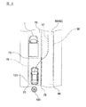
- the travel control system 111 includes a memory 2, a locator 3, a camera 4, an LRF (Laser Range Finder) 5, a steering amount detection unit 6, and a steering actuator 7.
- the travel control device 100 controls various actuators including the steering actuator 7 so that the own vehicle 101 can autonomously travel based on the information acquired from the memory 2, the locator 3, the camera 4, the LRF 5, and the steering amount detection unit 6. ..
- the memory 2 stores three-dimensional high-definition map information based on the road shape detected when traveling on an actual road using a data acquisition vehicle.
- the three-dimensional high-definition map information stored in the memory 2 includes the map information, boundary information at each map coordinate, two-dimensional position information, three-dimensional position information, road information, road attribute information, up information, down information, and lane. Identification information, connection destination lane information, etc. are included.
- Road information and road attributes include road width, radius of curvature, shoulder structure, road traffic regulations (speed limit, lane changeability), road confluences, branch points, toll gates, lane reduction positions, service areas. / Contains information such as parking areas.
- the locator 3 is composed of a GPS unit, a gyro sensor, a vehicle speed sensor, and the like.
- the locator 3 detects radio waves transmitted from a plurality of satellite communications by the GPS unit, periodically acquires the position information of the own vehicle 101, and acquires the position information of the own vehicle 101 and the angle acquired from the gyro sensor.
- the current position information of the own vehicle 101 is periodically detected based on the change information and the vehicle speed acquired from the vehicle speed sensor.
- the camera 4 is composed of an image sensor such as a CCD wide-angle camera, and is provided in the front and rear of the own vehicle 101 and on both sides as needed, and acquires image information by photographing the surroundings of the own vehicle 101.
- the camera 4 may be a stereo camera or an omnidirectional camera, and may include a plurality of image sensors. From the acquired image data, the camera 4 detects the road in front of the own vehicle 101 and structures around the road, road signs, signs, other vehicles, two-wheeled vehicles, bicycles, pedestrians, etc. as the surrounding conditions of the own vehicle 101. To do.
- the LRF5 is provided on the front, rear, and both sides of the own vehicle 101, and irradiates the periphery of the own vehicle 101 with millimeter waves or ultrasonic waves to scan a predetermined range around the own vehicle 101.
- the LRF5 detects obstacles such as other vehicles, motorcycles, bicycles, pedestrians, curbs on the shoulder of the road, guardrails, wall surfaces, and embankments existing around the own vehicle 101.
- the LRF 5 detects the relative position (direction) between the obstacle and the own vehicle 101, the relative speed of the obstacle, the distance from the own vehicle 101 to the obstacle, and the like as the surrounding conditions of the own vehicle 101.
- the steering amount detection unit 6 is, for example, a sensor that detects the rotation angle of the steering shaft (not shown), and detects the steering amount of the own vehicle 101.
- the steering actuator 7 is composed of, for example, a motor capable of transmitting torque to the steering shaft, and controls the steering of the own vehicle 101 according to a command value of automatic driving control by the traveling control device 100 or an operation of the steering wheel 103 by the driver.
- the travel control device 100 is composed of one or more computers and software installed on the computers.
- the travel control device 100 includes a ROM that stores a program for exerting an automatic driving control function, a CPU that executes the program stored in the ROM, and a RAM that functions as an accessible storage device.
- the travel control device 100 includes a lane planning unit 10, an override determination unit 20, a first travelable area generation unit 31, a second travelable area generation unit 41, a synthesis unit 45, an own vehicle travel track generation unit 50, and a route tracking control unit. Has 60.
- the travel control device 100 estimates its own position based on the position information of its own vehicle 9 and the map information of the memory 2 obtained by the locator 3 (step S1). Further, the travel control device 100 recognizes pedestrians and other obstacles around the own vehicle 101 by the camera 4 and the LRF 5 (step S2). Then, the self-position information estimated in step S1 and the information such as obstacles recognized in step S2 are expanded on the map information stored in the memory 2 (step S3).
- the destination is set on the map information of the memory 2 (step S4), and the route planning from the current location to the destination is performed. (Step S5).
- the action of the own vehicle 101 is determined based on the map information (step S6). Specifically, for example, at each position of a plurality of intersections existing on the planned route, in which direction the own vehicle 101 turns is determined.
- drive zone planning is performed on the map information of the memory 2 (step S7). Specifically, which lane the own vehicle 101 should drive in at a predetermined position or a predetermined interval on the route is appropriately set.
- the travel control device 100 uses the own vehicle 101 based on the input current location and destination position information, the set route information, the drive zone information, the obstacle information recognized by the cameras 4 and the LRF5, and the like.
- the target trajectory of (step S8) is set. Further, the travel control device 100 controls the behavior of various actuators of the own vehicle 101 so that the own vehicle 101 follows the target trajectory (step S9).
- the travel control method for the travel control device 100 to set the own vehicle travel trajectory as the target trajectory in step S8 described in FIG. 2 will be described in more detail with reference to FIGS. 1, 3 and 4.
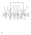
- the lane planning unit 10 of the travel control device 100 performs drive zone planning based on the map data of the memory 2 and the vehicle position information estimated by the locator 3, and the vehicle 101 performs drive zone planning. It is determined which lane to drive (step S11).
- the drive zone planning of the lane planning unit 10 corresponds to step S7 shown in FIG.
- the lane planning unit 10 performs drive zone planning so that the own vehicle 101 travels in the first lane 70 on the left side.
- the lane planning unit 10 acquires the leftmost boundary 77 and the right side boundary 78 of the first lane 70, and the own vehicle 101 travels between the leftmost boundary 77 and the right side boundary 78 of the first lane 70. Do drive zone planning as you do.
- the boundary 78 on the right side of the first lane 70 is a lane boundary line between the first lane 70 and the second lane 80 adjacent to the first lane 70.
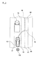
- the override determination unit 20 determines whether or not the control of the own vehicle 101 is switched from the automatic driving control to the override state and the lane is changed (step 12). Specifically, as shown in FIG. 4, when the own vehicle 101 is traveling in the first lane 70 due to the automatic driving control of the travel control device 100, and there is a road parking 1 in the traveling direction of the own vehicle 101. , The driver operates the steering wheel 103 to change lanes to the adjacent second lane 80 and try to avoid road parking 1. As a result, the control of the own vehicle 101 is overridden, and the own vehicle changes lanes.
- the override is a state in which the driver has control of the own vehicle 101.
- the second lane 80 is a lane existing in the direction in which the override of the own vehicle 101 is executed.
- the override determination unit 20 detects that the control of the own vehicle 101 is switched to the override state by detecting the steering control by the driver based on the steering amount detected by the steering amount detection unit 6, and the own vehicle 101 Determines whether or not to change lanes. Further, the override determination unit 20 detects the road parking 1 as an obstacle by the camera 4 and the LRF 5 mounted on the own vehicle 101, and when the override of the own vehicle 101 is detected, the own vehicle 101 May be expected to change lanes by overriding.
- the obstacle detected by the camera 4 and the LRF 5 mounted on the own vehicle 101 is not limited to the road parking 1, and may be a preceding vehicle, a bicycle, a two-wheeled vehicle, or the like.
- step S12 of FIG. 3 If it is determined in step S12 of FIG. 3 that the lane change of the own vehicle 101 is not performed by the override, the control proceeds to step S13, and the travel control device 100 generates a travelable area along the first lane 70. To do. In this case, the travelable area is not generated in the second lane 80.
- step S12 when it is determined by the override determination unit 20 that the control of the own vehicle 101 is switched to the override state and the lane change is performed, as shown in FIG. 4, the first travelable area generation unit 31 Generates a first travelable area 73 in which the own vehicle 101 can travel (step S14).
- the first travelable area 73 is generated along the predicted travel track 74 calculated according to the current steering angle and vehicle speed of the own vehicle 101 under the steering control of the driver.
- the predicted traveling track 74 may be calculated according to the current yaw rate and vehicle speed of the own vehicle 101.
- the second travelable area generation unit 41 performs the second The second travelable area 82 is generated according to the shape of the lane 80 (step S15).
- the position of the second lane 80 is recognized based on the map information stored in the memory 2 and the own vehicle position information estimated by the locator 3.
- the second travelable area generation unit 41 has acquired the boundary 78 on the left side of the second lane 80 and the boundary 88 on the right side of the second lane 80 from the map information of the memory 2. Therefore, the second travelable area 82 is generated between the left boundary 78 and the right boundary 88 of the second lane 80.
- the boundary 78 on the left side of the second lane 80 is a lane boundary line between the first lane 70 and the second lane 80.
- the second travelable region 82 is generated from the position 82b on the own vehicle 101 side in the traveling direction of the first lane 70 at least from the position 82a where the predicted travel track 74 is in contact with the second lane 80. Is set to be done.
- the synthesizing unit 45 combines the first travelable area 73 and the second travelable area 82 to generate the third travelable area 94 (step S16). Further, the own vehicle traveling track generation unit 50 generates the own vehicle traveling track 95 within the third travelable region 94 (step S17). Further, when it is determined that the lane change of the own vehicle 101 is not performed by the override, the own vehicle traveling track generation unit 50 generates the own vehicle traveling track 95 within the travelable area along the first lane 70. (Step S17).
- the control from the determination of the override of the own vehicle 101 by the override determination unit 20 to the generation of the own vehicle travel track 95 by the own vehicle travel track generation unit 50 corresponds to the track control in step S8 shown in FIG.
- the route tracking control unit 60 controls the behavior of the steering actuator 7 of the own vehicle 101 so that the own vehicle 101 follows the traveling track 95 of the own vehicle and travels (step S18).
- the route following control unit 60 controls the behavior of the own vehicle 101 so that the own vehicle 101 travels in the first travelable region 73 in the first lane 70.
- the route tracking control unit 60 controls the behavior of the own vehicle 101 so that the own vehicle 101 travels in the second travelable area 82 in the second lane 80.
- the control of the steering actuator 7 by the path tracking control unit 60 corresponds to the behavior control of the vehicle in step S9 shown in FIG.
- the travel control device 100 sets the first travelable area 73 and the second travelable area 82 in which the own vehicle 101 can travel when it is determined that the own vehicle 101 changes lanes by overriding. It is connected to generate a third travelable area 94.
- the first travelable area 73 is generated in the first lane 70 in which the own vehicle 101 travels.
- the second travelable area 82 is generated in the second lane 80 existing in the direction in which the override of the own vehicle 101 is executed. Then, the travel control device 100 generates the own vehicle travel track 95 within the third travelable region 94.
- the travel control device 100 smoothly generates the own vehicle traveling track 95 that the own vehicle 101 should follow while reflecting the driver's request. ..
- the traveling control of the own vehicle 101 can be smoothly returned to the automatic driving control again from the override state. Therefore, the behavior of the own vehicle 101 when the lane is changed by overriding is stable.
- the travel control device 100 generates a travelable area in the first lane 70 even when the own vehicle 101 does not change lanes due to the override. Then, the travel control device 100 generates an own vehicle traveling track for traveling the own vehicle 101 within the travelable area generated in the first lane 70. In this case, the travel control device 100 does not generate a travelable area in the adjacent second lane 80 in order to stably continue the travel of the own vehicle 101 in the first lane 70. Therefore, the travel control device 100 according to this embodiment generates a second travelable area 82 in the second lane 80 at a timing when the lane change is required, while traveling in the first lane 70 when the lane change is not required. Generate the own vehicle driving track within the possible area. As a result, even when the own vehicle 101 does not change lanes due to the override, the travel control device 100 can generate an appropriate own vehicle travel track, and the own vehicle 101 is stable along the first lane 70. You can continue running.
- the second lane 82 is set in the adjacent second lane 80. It may be generated. That is, in the flowchart of FIG. 3, the generation of the first travelable area is shown as step S14, but the first travelable area 73 of step S14 is generated between steps S11 and S12 of the flowchart of FIG. Processing may come. If YES is determined in the determination that there is a lane change due to the override in step S12, the process may flow from step S12 to step S15 as much as step S14 comes between steps S11 and S12.
- the first travelable area 73 is generated based on the predicted travel track 74 according to the override of the own vehicle 101. This makes it easier to generate the own vehicle traveling track 95 based on the traveling track required by the driver. Therefore, the own vehicle traveling track 95 becomes a track that reflects the driver's request, and the discomfort felt by the driver during traveling can be suppressed.
- the second travelable area 82 is set so as to be generated from the position 82b on the own vehicle 101 side in the traveling direction of the first lane 70 at least from the position 82a where the predicted travel track 74 is in contact with the second lane 80. ..
- the second travelable area 82 is formed so as to match the shape of the second lane 80 and along the extension direction of the second lane 80. As a result, the own vehicle 101 can change lanes to the second lane 80 more smoothly along the own vehicle traveling track 95.
- the override determination unit 20 uses the own vehicle. It is determined that 101 changes lanes to the second lane 80 by overriding. As a result, the travel control device 100 can surely generate the third travelable area 94 and the own vehicle travel track 95, so that the own vehicle 101 travels more smoothly while avoiding obstacles and changes lanes. be able to.
- the route tracking control unit 60 of the travel control device 100 controls the behavior of the own vehicle 101 so that the own vehicle 101 travels in the first travelable area 73 in the first lane 70. Further, the route tracking control unit 60 controls the behavior of the own vehicle 101 so that the own vehicle 101 travels in the second travelable area 82 in the second lane 80. As a result, the travel control device 300 can smoothly travel the own vehicle 101 along the own vehicle travel track 95 while reflecting the steering control by the driver in the behavior of the own vehicle 101.
- the first travelable area 73 is generated based on the current steering angle and vehicle speed of the own vehicle 101, or the predicted travel track 74 calculated from the current yaw rate and vehicle speed.
- the travel control device 100 can generate the own vehicle travel track 95 according to the actual travel conditions and the driver's request.
- the travel control device 100 controls the travel of the own vehicle 101 so as to travel along the own vehicle travel track 95 while decelerating at the timing when the own vehicle 101 changes lanes by overriding. As a result, the own vehicle 101 can more reliably follow the own vehicle traveling track 95 and travel.
- the width of the first travelable area 73 is variable, and when the driver operates the steering wheel 103 more than once when changing lanes, the width of the first travelable area 73 may be narrower.
- the narrower the width of the first travelable region 73 the stronger the steering control of the driver in the overriding state is reflected in the generation of the own vehicle traveling track 95.
- the wider the width of the first travelable region 73 the smoother the own vehicle travel track 95. Further, the width of the first travelable area 73 may change according to the travel mode of the own vehicle 101.
- the travel control device 200 according to the second embodiment of the present invention will be described with reference to FIG.
- the first travelable area 76, the third travelable area 96, and the own vehicle travel track 97 are the first travelable area 73, the third travelable area 94, and the own vehicle travel track 95 of the first embodiment. It is formed in a different manner from.
- the travel control device 200 according to the second embodiment has the same configuration as the travel control device 100 according to the first embodiment shown in FIG. Further, the flow of the travel control method for setting the own vehicle travel track 97 by the travel control device 200 is the same as the flow shown in FIG. Further, since the same reference numerals as those shown in FIGS. 1 to 4 indicate the same or similar configuration, detailed description thereof will be omitted.
- the camera 4 and the LRF 5 detect the road parking 1 as an obstacle. Then, the override determination unit 20 detects the override of the own vehicle 101, and determines that the own vehicle 101 changes lanes to the second lane 80 by the override.
- the first travelable area generation unit 31 sets the first travelable area 76 in accordance with the shape of the first lane 70. Generate. The first travelable area 76 is generated on the first lane 70 up to the point 75 on the front side of the road parking 1.
- the second travelable area generation unit 41 performs the second A second travelable area 82 is generated along the lane 80.
- the synthesis unit 45 combines the first travelable area 76 and the second travelable area 82 to generate the third travelable area 96. Further, the own vehicle traveling track generation unit 50 generates the own vehicle traveling track 97 within the third travelable region 96.
- the travel control device 200 generates the first travelable area 76 according to the shape of the first lane 70, and creates the second travelable area 82 according to the shape of the second lane 80. Generate. Then, the first travelable area 76 and the second travelable area 82 are connected, and the third travelable area 96 is generated. The travel control device 200 generates the own vehicle travel track 97 within the third travelable region 96. As a result, the area in which the own vehicle 101 can travel can be set widely, so that the area in which the own vehicle traveling track 97 can be generated is expanded. Therefore, it is possible to generate the own vehicle traveling track 97 that does not give a sense of discomfort to the occupants of the own vehicle 101.
- the first travelable area 76 is generated on the first lane 70 up to the point 75 on the front side of the road parking 1 as an obstacle detected by the camera 4 and the LRF5. As a result, the own vehicle 101 can smoothly change lanes while surely avoiding the road parking 1.
- the travel control device 300 of the control system 102 shown in FIG. 6 the first travelable area generation unit 31 of the travel control device 100 shown in FIG. 1 is used as the first track generation unit 30, and the second travelable area generation unit 41 is designated as the second travelable area generation unit 41.
- the two orbit generation units 40 are replaced with each other. Further, the travel control device 300 does not have a configuration corresponding to the synthesis unit 45 of the travel control device 100.
- the first track generation unit 30 when the control of the own vehicle 101 is switched to the override state by the override determination unit 20 and it is determined that the lane change is performed, the first track generation unit 30 overrides the own vehicle 101.
- the first orbit 79 corresponding to the above is generated (step S24). Specifically, the first track 79 is generated according to the current steering angle and vehicle speed of the own vehicle 101 under the steering control of the driver. Further, the first track 79 may be generated according to the current yaw rate and vehicle speed of the own vehicle 101.
- the second track generation unit 40 causes the second lane 80.
- a second orbit 81 is generated along the line (step S25). The second track 81 is generated so as to pass through the center between the boundaries 78 and 88 of the second lane 80.
- the own vehicle traveling track generation unit 50 generates the own vehicle traveling track 98 by combining the first track 79 and the second track 81 (step S26). Further, the route tracking control unit 60 controls the behavior of the steering actuator 7 of the own vehicle 101 so that the own vehicle 101 travels following the own vehicle traveling track 98 (step S18). If it is determined in step S12 that the own vehicle 101 does not change lanes by overriding, the route tracking control unit 60 follows the own vehicle traveling track set in advance by the own vehicle 101 and follows the first lane. The behavior of the own vehicle 101 is controlled so as to travel 70 (step S18).
- the override determination unit 20 determines the override of the own vehicle 101
- the first track generation unit 30 generates the first track 79
- the second track generation unit 40 generates the second track 81
- the own vehicle travel track generation unit The generation of the own vehicle traveling track 98 by 50 corresponds to the track control in step S8 shown in FIG.
- the travel control device 300 when the own vehicle 101 changes lanes by overriding, the travel control device 300 according to this embodiment combines the first track 79 and the second track 81 to generate the own vehicle travel track 98. Then, the travel control device 300 controls the steering actuator 7 of the own vehicle 101 so that the own vehicle 101 travels following the own vehicle travel track 98.
- the running control of the own vehicle 101 can smoothly return to the automatic driving control again from the overriding state. Therefore, the behavior of the own vehicle 101 when the lane is changed by overriding is stable.
- the first track 79 is generated according to the current steering angle and vehicle speed of the own vehicle 101, or the current yaw rate and vehicle speed.
- the travel control device 300 can generate the own vehicle travel track 98 according to the actual travel conditions and the driver's request.
- the travel control device 300 is capable of second travel generated according to the shape of the first track 79 corresponding to the override of the own vehicle 101 and the shape of the second lane 80 as shown in FIG.
- the own vehicle traveling track 98 may be generated based on the region 82.
- the own vehicle 101 may change lanes by overriding after temporarily stopping before the road parking 1. Further, when the traveling own vehicle 101 decelerates before the road parking 1 and changes lanes, the deceleration of the own vehicle 101 may be changed according to the steering amount of the driver in the overridden state.
- the first lane 70 corresponds to the traveling lane according to the present invention
- the second lane 80 corresponds to another lane according to the present invention.
Abstract
Description
以下、本発明の最良の実施形態である第1実施形態に係る車両の走行制御装置100について、図1~4に基づいて、説明する。
図1に示すように、走行制御システム111は、自車両101を自律走行させるための自動運転制御を実行する走行制御装置100を有している。走行制御システム111は、メモリ2、ロケータ3、カメラ4、LRF(Laser Range Finder,レーザレンジファインダ)5、操舵量検出部6及びステアリングアクチュエータ7を含む。走行制御装置100は、メモリ2、ロケータ3、カメラ4、LRF5及び操舵量検出部6から取得した情報に基づいて、自車両101が自律走行できるように、ステアリングアクチュエータ7を含む各種アクチュエータを制御する。
まず、走行制御装置100は、ロケータ3によって得られた自車両9の位置情報及びメモリ2の地図情報により、自己位置の推定を行う(ステップS1)。また、走行制御装置100は、カメラ4及びLRF5によって、自車両101の周囲の歩行者その他の障害物を認識する(ステップS2)。そして、ステップS1で推定された自己位置の情報と、ステップS2で認識された障害物等の情報とが、メモリ2に格納された地図情報の上に展開される(ステップS3)。
まず、図3に示すように、走行制御装置100の車線計画部10は、メモリ2の地図データ及びロケータ3によって推定された自車位置情報に基づいて、ドライブゾーンプランニングを行い、自車両101がどの車線を走行すべきかを決定する(ステップS11)。ここで、車線計画部10のドライブゾーンプランニングは、図2に示すステップS7に対応する。図4の例では、車線計画部10は、自車両101が左側の第1車線70を走行するように、ドライブゾーンプランニングを行う。すなわち、車線計画部10は、第1車線70の左端の境界77と右側の境界78とを取得し、自車両101が第1車線70の左端の境界77と右側の境界78との間を走行するようにドライブゾーンプランニングを行う。なお、第1車線70の右側の境界78は、第1車線70と、第1車線70に隣接する第2車線80との間の車線境界線である。
次に、本発明の第2実施形態に係る走行制御装置200について、図5に基づいて説明する。この実施形態では、第1走行可能領域76、第3走行可能領域96及び自車両走行軌道97が、第1実施形態の第1走行可能領域73、第3走行可能領域94及び自車両走行軌道95とは異なる態様で形成される。なお、第2実施形態に係る走行制御装置200は、図1に示す第1実施形態に係る走行制御装置100と同一の構成を有する。また、走行制御装置200によって自車両走行軌道97を設定するための走行制御方法のフローは、図4に示すフローと同一である。さらに、図1~4に記載されている符号と同一の符号は、同一又は同様の構成を示しているため、詳細な説明は省略する。
次に、本発明の第3実施形態に係る走行制御装置300について、図6~8に基づいて説明する。図1~5に記載されている符号と同一の符号は、同一又は同様の構成を示しているため、詳細な説明は省略する。
101…自車両
1…路駐車
20…オーバーライド判定部
30…第1軌道生成部
31…第1走行可能領域生成部
40…第2軌道生成部
41…第2走行可能領域生成部
45…合成部
50…自車両走行軌道生成部
60…経路追従制御部
70…第1車線(走行車線)
79…第1軌道
73,76…第1走行可能領域
74…予測走行軌道
80…第2車線(他車線)
81…第2軌道
82…第2走行可能領域
95,97,98…自車両走行軌道
94,96…第3走行可能領域
Claims (16)
- 走行車線に沿って自律走行する自車両が、オーバーライドによって前記走行車線と異なる他車線に車線変更するか否かを判定し、
前記自車両がオーバーライドによって車線変更すると判定された場合、
前記走行車線に、前記自車両が走行可能な第1走行可能領域を生成し、
前記自車両のオーバーライドが実行された方向の前記他車線に、前記自車両が走行可能な第2走行可能領域を生成し、
前記第1走行可能領域と前記第2走行可能領域とを接続して第3走行可能領域を生成し、
前記第3走行可能領域内で自車両走行軌道を生成し、
前記自車両がオーバーライドによって車線変更する場合、前記自車両が前記自車両走行軌道に沿って走行するように前記自車両の挙動を制御する、車両の走行制御方法。 - 前記第1走行可能領域は、前記自車両のオーバーライドに応じた予測走行軌道に基づいて生成される、請求項1に記載の車両の走行制御方法。
- 前記第1走行可能領域は、前記自車両の現在の舵角及び車速から算出される前記予測走行軌道に基づいて生成される、請求項2に記載の車両の走行制御方法。
- 前記第1走行可能領域は、前記自車両の現在のヨーレート及び車速から算出される前記予測走行軌道に基づいて生成される、請求項2に記載の車両の走行制御方法。
- 前記第2走行可能領域は、前記予測走行軌道が前記他車線に接する位置よりも少なくとも前記走行車線の進行方向の自車両側の位置から生成されるように設定される、請求項2~4のいずれか一項に記載の車両の走行制御方法。
- 前記第2走行可能領域は、前記他車線の形状に合わせて生成される、請求項1~5のいずれか一項に記載の車両の走行制御方法。
- 前記自車両の前方の前記走行車線上に障害物があることが検出され、かつ、前記自車両のオーバーライドが検出された場合に、前記自車両がオーバーライドによって前記他車線に車線変更すると判定する、請求項1~6のいずれか一項に記載の車両の走行制御方法。
- 前記第1走行可能領域は、前記自車両が走行する前記走行車線の形状に合わせて生成される、請求項1に記載の車両の走行制御方法。
- 前記自車両の前方の前記走行車線上に障害物があることが検出され、かつ、前記オーバーライドが検出された場合に、前記自車両はオーバーライドによって前記他車線に車線変更すると判定され、
前記第1走行可能領域は、前記障害物の手前側の地点まで、前記走行車線に沿って生成される、請求項8に記載の車両の走行制御方法。 - 前記自車両が前記自車両走行軌道に沿って走行するように前記自車両の挙動を制御する場合において、
前記走行車線内では、前記自車両が前記第1走行可能領域を走行するように前記自車両の挙動を制御し、
前記他車線内では、前記自車両が前記第2走行可能領域を走行するように前記自車両の挙動を制御する、請求項1~9のいずれか一項に記載の車両の走行制御方法。 - 前記自車両がオーバーライドによって車線変更するタイミングで、前記自車両が減速するように前記自車両の挙動を制御する、請求項1~10のいずれか一項に記載の車両の走行制御方法。
- 走行車線に沿って自律走行する自車両が、オーバーライドによって前記走行車線と異なる他車線に車線変更するか否かを判定し、
前記自車両がオーバーライドによって車線変更すると判定された場合、
前記自車両のオーバーライドに応じた第1軌道を生成し、
前記自車両のオーバーライドが実行された方向の前記他車線に、前記自車両が走行可能な第2走行可能領域を生成し、
前記第1軌道及び前記第2走行可能領域に基づいて、自車両走行軌道を生成し、
前記自車両がオーバーライドによって車線変更する場合、前記自車両が前記自車両走行軌道に沿って走行するように前記自車両の挙動を制御する、車両の走行制御方法。 - 走行車線に沿って自律走行する自車両が、オーバーライドによって前記走行車線と異なる他車線に車線変更するか否かを判定し、
前記自車両がオーバーライドによって車線変更すると判定された場合、
前記自車両のオーバーライドに応じた第1軌道を生成し、
前記走行車線と異なる前記他車線に沿った第2軌道を生成し、
前記第1軌道と前記第2軌道とを接続して自車両走行軌道を生成し、
前記自車両がオーバーライドによって車線変更する場合、前記自車両が前記自車両走行軌道に沿って走行するように前記自車両の挙動を制御する、車両の走行制御方法。 - 前記第1軌道は、前記自車両の現在の舵角及び車速に応じて生成される請求項13に記載の車両の走行制御方法。
- 前記第1軌道は、前記自車両の現在のヨーレート及び車速に応じて生成される請求項13に記載の車両の走行制御方法。
- 走行車線に沿って自律走行する自車両が、オーバーライドによって前記走行車線と異なる他車線に車線変更することを判定するオーバーライド判定部と、
前記自車両が走行する車線に、前記自車両が走行可能な第1走行可能領域を生成する第1走行可能領域生成部と、
前記自車両のオーバーライドが実行された方向の前記他車線に、前記自車両が走行可能な第2走行可能領域を生成する第2走行可能領域生成部と、
前記第1走行可能領域と前記第2走行可能領域とを結合して第3走行可能領域を生成する合成部と、
前記第3走行可能領域内で自車両走行軌道を生成する自車両走行軌道生成部と、
前記自車両がオーバーライドによって車線変更する場合、前記自車両が前記自車両走行軌道に沿って走行するように前記自車両の挙動を制御する経路追従制御部とを備える、車両の走行制御装置。
Priority Applications (5)
| Application Number | Priority Date | Filing Date | Title |
|---|---|---|---|
| US17/618,200 US11780474B2 (en) | 2019-06-13 | 2019-06-13 | Vehicle travel control method and vehicle travel control device |
| PCT/IB2019/000590 WO2020249989A1 (ja) | 2019-06-13 | 2019-06-13 | 車両の走行制御方法及び走行制御装置 |
| JP2021525388A JP7226544B2 (ja) | 2019-06-13 | 2019-06-13 | 車両の走行制御方法及び走行制御装置 |
| EP19932260.3A EP3985355A4 (en) | 2019-06-13 | 2019-06-13 | VEHICLE MOVEMENT CONTROL METHOD AND DEVICE |
| CN201980097476.2A CN114207380B (zh) | 2019-06-13 | 2019-06-13 | 车辆的行驶控制方法及行驶控制装置 |
Applications Claiming Priority (1)
| Application Number | Priority Date | Filing Date | Title |
|---|---|---|---|
| PCT/IB2019/000590 WO2020249989A1 (ja) | 2019-06-13 | 2019-06-13 | 車両の走行制御方法及び走行制御装置 |
Publications (1)
| Publication Number | Publication Date |
|---|---|
| WO2020249989A1 true WO2020249989A1 (ja) | 2020-12-17 |
Family
ID=73780934
Family Applications (1)
| Application Number | Title | Priority Date | Filing Date |
|---|---|---|---|
| PCT/IB2019/000590 WO2020249989A1 (ja) | 2019-06-13 | 2019-06-13 | 車両の走行制御方法及び走行制御装置 |
Country Status (5)
| Country | Link |
|---|---|
| US (1) | US11780474B2 (ja) |
| EP (1) | EP3985355A4 (ja) |
| JP (1) | JP7226544B2 (ja) |
| CN (1) | CN114207380B (ja) |
| WO (1) | WO2020249989A1 (ja) |
Cited By (1)
| Publication number | Priority date | Publication date | Assignee | Title |
|---|---|---|---|---|
| CN113799797A (zh) * | 2021-07-27 | 2021-12-17 | 北京三快在线科技有限公司 | 轨迹规划方法、装置、存储介质及电子设备 |
Citations (6)
| Publication number | Priority date | Publication date | Assignee | Title |
|---|---|---|---|---|
| JP2016215790A (ja) * | 2015-05-19 | 2016-12-22 | 株式会社デンソー | 車線変更計画生成装置、車線変更計画生成方法 |
| JP2017052486A (ja) | 2015-09-11 | 2017-03-16 | 株式会社ジェイテクト | ステアリング装置 |
| JP2017165153A (ja) * | 2016-03-14 | 2017-09-21 | 本田技研工業株式会社 | 車両制御装置、車両制御方法、および車両制御プログラム |
| JP2018202876A (ja) * | 2017-05-30 | 2018-12-27 | 日産自動車株式会社 | 先行車判定方法及び先行車判定装置 |
| JP2018203120A (ja) * | 2017-06-06 | 2018-12-27 | トヨタ自動車株式会社 | 操舵支援装置 |
| JP2019034627A (ja) * | 2017-08-14 | 2019-03-07 | 本田技研工業株式会社 | 車両制御装置、車両制御方法、およびプログラム。 |
Family Cites Families (12)
| Publication number | Priority date | Publication date | Assignee | Title |
|---|---|---|---|---|
| US9187117B2 (en) * | 2012-01-17 | 2015-11-17 | Ford Global Technologies, Llc | Autonomous lane control system |
| CN103646298B (zh) * | 2013-12-13 | 2018-01-02 | 中国科学院深圳先进技术研究院 | 一种自动驾驶方法及系统 |
| DE102015201878A1 (de) * | 2015-02-04 | 2016-08-04 | Continental Teves Ag & Co. Ohg | Halbautomatisierter Spurwechsel |
| JP6376059B2 (ja) * | 2015-07-06 | 2018-08-22 | トヨタ自動車株式会社 | 自動運転車両の制御装置 |
| CN108352116B (zh) * | 2015-07-31 | 2022-04-05 | 日立安斯泰莫株式会社 | 自身车辆周边信息管理装置 |
| JP6558239B2 (ja) * | 2015-12-22 | 2019-08-14 | アイシン・エィ・ダブリュ株式会社 | 自動運転支援システム、自動運転支援方法及びコンピュータプログラム |
| CN108778885B (zh) * | 2016-03-15 | 2021-09-10 | 本田技研工业株式会社 | 车辆控制系统、车辆控制方法及存储介质 |
| US20180188031A1 (en) * | 2016-08-31 | 2018-07-05 | Faraday&Future Inc. | System and method for calibrating vehicle dynamics expectations for autonomous vehicle navigation and localization |
| DE102016117438A1 (de) * | 2016-09-16 | 2018-03-22 | Knorr-Bremse Systeme für Nutzfahrzeuge GmbH | Verfahren und Vorrichtung zum Steuern einer Bewegung eines Fahrzeugs und Fahrzeugbewegungssteuersystem |
| US10809719B2 (en) * | 2017-08-29 | 2020-10-20 | Uatc, Llc | Systems and methods of controlling an autonomous vehicle using an enhanced trajectory following configuration |
| US10614717B2 (en) * | 2018-05-17 | 2020-04-07 | Zoox, Inc. | Drive envelope determination |
| US11639195B2 (en) * | 2019-02-27 | 2023-05-02 | Steering Solutions Ip Holding Corporation | Lane change assistant |
-
2019
- 2019-06-13 JP JP2021525388A patent/JP7226544B2/ja active Active
- 2019-06-13 WO PCT/IB2019/000590 patent/WO2020249989A1/ja active Application Filing
- 2019-06-13 EP EP19932260.3A patent/EP3985355A4/en active Pending
- 2019-06-13 US US17/618,200 patent/US11780474B2/en active Active
- 2019-06-13 CN CN201980097476.2A patent/CN114207380B/zh active Active
Patent Citations (6)
| Publication number | Priority date | Publication date | Assignee | Title |
|---|---|---|---|---|
| JP2016215790A (ja) * | 2015-05-19 | 2016-12-22 | 株式会社デンソー | 車線変更計画生成装置、車線変更計画生成方法 |
| JP2017052486A (ja) | 2015-09-11 | 2017-03-16 | 株式会社ジェイテクト | ステアリング装置 |
| JP2017165153A (ja) * | 2016-03-14 | 2017-09-21 | 本田技研工業株式会社 | 車両制御装置、車両制御方法、および車両制御プログラム |
| JP2018202876A (ja) * | 2017-05-30 | 2018-12-27 | 日産自動車株式会社 | 先行車判定方法及び先行車判定装置 |
| JP2018203120A (ja) * | 2017-06-06 | 2018-12-27 | トヨタ自動車株式会社 | 操舵支援装置 |
| JP2019034627A (ja) * | 2017-08-14 | 2019-03-07 | 本田技研工業株式会社 | 車両制御装置、車両制御方法、およびプログラム。 |
Cited By (2)
| Publication number | Priority date | Publication date | Assignee | Title |
|---|---|---|---|---|
| CN113799797A (zh) * | 2021-07-27 | 2021-12-17 | 北京三快在线科技有限公司 | 轨迹规划方法、装置、存储介质及电子设备 |
| CN113799797B (zh) * | 2021-07-27 | 2022-07-12 | 北京三快在线科技有限公司 | 轨迹规划方法、装置、存储介质及电子设备 |
Also Published As
| Publication number | Publication date |
|---|---|
| JP7226544B2 (ja) | 2023-02-21 |
| JPWO2020249989A1 (ja) | 2020-12-17 |
| CN114207380B (zh) | 2024-01-16 |
| US20220266858A1 (en) | 2022-08-25 |
| CN114207380A (zh) | 2022-03-18 |
| EP3985355A4 (en) | 2022-09-07 |
| US11780474B2 (en) | 2023-10-10 |
| EP3985355A1 (en) | 2022-04-20 |
Similar Documents
| Publication | Publication Date | Title |
|---|---|---|
| EP3611069B1 (en) | Vehicle control device | |
| RU2741126C1 (ru) | Способ управления движением и устройство управления движением для транспортного средства с помощью при вождении | |
| JP6939428B2 (ja) | 車両制御装置 | |
| JP2019156174A (ja) | 車両制御装置、車両、車両制御方法およびプログラム | |
| JP6825081B2 (ja) | 車両制御装置及び車両制御方法 | |
| US20170351262A1 (en) | Target pathway generating device and driving control device | |
| RU2745936C1 (ru) | Устройство определения положения стоп-линии и система управления транспортным средством | |
| US10854083B2 (en) | Vehicle control device, vehicle control method, and storage medium | |
| EP3842315B1 (en) | Autonomous driving vehicle three-point turn | |
| JP7439911B2 (ja) | 走行支援方法、及び、走行支援装置 | |
| WO2016189727A1 (ja) | 走行制御装置及び方法 | |
| JP7035408B2 (ja) | 車両走行制御方法及び装置 | |
| JP7379033B2 (ja) | 運転支援方法及び運転支援装置 | |
| WO2018211645A1 (ja) | 運転支援方法及び運転支援装置 | |
| JP2021041754A (ja) | 運転制御方法及び運転制御装置 | |
| RU2724213C1 (ru) | Способ генерации целевой скорости и устройство генерации целевой скорости транспортного средства с содействием вождению | |
| US11577758B2 (en) | Autonomous vehicle park-and-go scenario design | |
| JP7314995B2 (ja) | 車両の走行制御方法及び走行制御装置 | |
| WO2020249989A1 (ja) | 車両の走行制御方法及び走行制御装置 | |
| JP7141421B2 (ja) | 車両制御装置、車両制御方法、およびプログラム | |
| RU2783328C1 (ru) | Способ управления движением и устройство управления движением для транспортного средства | |
| JP7258677B2 (ja) | 運転制御方法及び運転制御装置 | |
| WO2024069690A1 (ja) | 運転支援方法及び運転支援装置 | |
| JP2023154622A (ja) | 運転支援方法及び運転支援装置 | |
| JP2023169524A (ja) | 車両の運転支援方法及び運転支援装置 |
Legal Events
| Date | Code | Title | Description |
|---|---|---|---|
| 121 | Ep: the epo has been informed by wipo that ep was designated in this application |
Ref document number: 19932260 Country of ref document: EP Kind code of ref document: A1 |
|
| ENP | Entry into the national phase |
Ref document number: 2021525388 Country of ref document: JP Kind code of ref document: A |
|
| NENP | Non-entry into the national phase |
Ref country code: DE |
|
| WWE | Wipo information: entry into national phase |
Ref document number: 2019932260 Country of ref document: EP |
|
| ENP | Entry into the national phase |
Ref document number: 2019932260 Country of ref document: EP Effective date: 20220113 |