WO2020246614A1 - 気密コネクタ - Google Patents
気密コネクタ Download PDFInfo
- Publication number
- WO2020246614A1 WO2020246614A1 PCT/JP2020/022507 JP2020022507W WO2020246614A1 WO 2020246614 A1 WO2020246614 A1 WO 2020246614A1 JP 2020022507 W JP2020022507 W JP 2020022507W WO 2020246614 A1 WO2020246614 A1 WO 2020246614A1
- Authority
- WO
- WIPO (PCT)
- Prior art keywords
- airtight
- partition wall
- connector
- hole
- space
- Prior art date
- Legal status (The legal status is an assumption and is not a legal conclusion. Google has not performed a legal analysis and makes no representation as to the accuracy of the status listed.)
- Ceased
Links
Images





Classifications
-
- H—ELECTRICITY
- H01—ELECTRIC ELEMENTS
- H01R—ELECTRICALLY-CONDUCTIVE CONNECTIONS; STRUCTURAL ASSOCIATIONS OF A PLURALITY OF MUTUALLY-INSULATED ELECTRICAL CONNECTING ELEMENTS; COUPLING DEVICES; CURRENT COLLECTORS
- H01R9/00—Structural associations of a plurality of mutually-insulated electrical connecting elements, e.g. terminal strips or terminal blocks; Terminals or binding posts mounted upon a base or in a case; Bases therefor
- H01R9/16—Fastening of connecting parts to base or case; Insulating connecting parts from base or case
-
- H—ELECTRICITY
- H01—ELECTRIC ELEMENTS
- H01R—ELECTRICALLY-CONDUCTIVE CONNECTIONS; STRUCTURAL ASSOCIATIONS OF A PLURALITY OF MUTUALLY-INSULATED ELECTRICAL CONNECTING ELEMENTS; COUPLING DEVICES; CURRENT COLLECTORS
- H01R13/00—Details of coupling devices of the kinds covered by groups H01R12/70 or H01R24/00 - H01R33/00
- H01R13/46—Bases; Cases
- H01R13/52—Dustproof, splashproof, drip-proof, waterproof, or flameproof cases
- H01R13/521—Sealing between contact members and housing, e.g. sealing insert
-
- H—ELECTRICITY
- H01—ELECTRIC ELEMENTS
- H01R—ELECTRICALLY-CONDUCTIVE CONNECTIONS; STRUCTURAL ASSOCIATIONS OF A PLURALITY OF MUTUALLY-INSULATED ELECTRICAL CONNECTING ELEMENTS; COUPLING DEVICES; CURRENT COLLECTORS
- H01R43/00—Apparatus or processes specially adapted for manufacturing, assembling, maintaining, or repairing of line connectors or current collectors or for joining electric conductors
- H01R43/20—Apparatus or processes specially adapted for manufacturing, assembling, maintaining, or repairing of line connectors or current collectors or for joining electric conductors for assembling or disassembling contact members with insulating base, case or sleeve
-
- H—ELECTRICITY
- H01—ELECTRIC ELEMENTS
- H01R—ELECTRICALLY-CONDUCTIVE CONNECTIONS; STRUCTURAL ASSOCIATIONS OF A PLURALITY OF MUTUALLY-INSULATED ELECTRICAL CONNECTING ELEMENTS; COUPLING DEVICES; CURRENT COLLECTORS
- H01R13/00—Details of coupling devices of the kinds covered by groups H01R12/70 or H01R24/00 - H01R33/00
- H01R13/02—Contact members
- H01R13/03—Contact members characterised by the material, e.g. plating, or coating materials
-
- H—ELECTRICITY
- H01—ELECTRIC ELEMENTS
- H01R—ELECTRICALLY-CONDUCTIVE CONNECTIONS; STRUCTURAL ASSOCIATIONS OF A PLURALITY OF MUTUALLY-INSULATED ELECTRICAL CONNECTING ELEMENTS; COUPLING DEVICES; CURRENT COLLECTORS
- H01R4/00—Electrically-conductive connections between two or more conductive members in direct contact, i.e. touching one another; Means for effecting or maintaining such contact; Electrically-conductive connections having two or more spaced connecting locations for conductors and using contact members penetrating insulation
- H01R4/02—Soldered or welded connections
Definitions
- the present invention relates to an airtight connector that makes an electrical connection via a conductive terminal while maintaining airtightness.
- the performance of small electronic components is greatly affected by the humidity and the viscosity of the enclosed gas. Therefore, in order to prevent corrosion of internal circuits due to humidity and malfunction due to changes in the viscosity of the gas, it is sealed and sealed with a vacuum or an inert gas. Has been done.
- a closed container is used, and in order to introduce a power source without impairing the airtightness of the closed container and to extract internal sensor signals, etc.
- An airtight (hermetic) connector with airtightness is used.
- a through hole is provided in a ceramic plate for blocking the internal atmosphere from the external atmosphere, an insulating substrate such as a glass epoxy plate, or a metal plate.
- an insulating substrate such as a glass epoxy plate, or a metal plate.
- a metal pin for electrical connection is inserted into this through hole, and the gap is closed by glass sealing, silver brazing, soldering, or the like for joining.
- the airtight connector according to the invention according to claim 1 of the present invention maintains, for example, airtightness between a first space in which a small electronic component is sealed together with an inert gas and a second space outside the first space. Moreover, it is an airtight connector for electrically connecting the first conductor in the first space and the second conductor in the second space, and connects the first space and the second space.
- the first conductive portion is characterized in that it is formed as an integral member with respect to the covering portion, and is different from covering the hole by joining using a plurality of conductive members. This is because when a plurality of conductive members are used, there is a concern about leakage from the joint portion.
- the conductive portion is formed by repeatedly plating the covering portion, for example, a plurality of times, the conductive portion is formed as an integral or a single member. In this case, the leak can be effectively prevented.
- the airtight connector according to the second aspect of the present invention is characterized in that the first conductive portion is in close contact with the surface of the partition wall portion and integrally covers the hole and its periphery. With such a configuration, the contact area between the partition wall portion and the conductive portion is increased, so that the conductive portion is less likely to be peeled off from the partition wall portion and the breaking strength of the airtight connector is improved.
- the first conductive portion is characterized in that it integrally covers the hole and its periphery. This case is also characterized in that the portion to be covered is covered with a single member, which is different from covering the hole by joining using a plurality of conductive members.
- the airtight connector according to the invention according to the third aspect of the present invention has a second conductive portion provided on the surface of the partition wall portion so as to be insulated from the first conductive portion in the invention according to the first aspect.
- the conductive portion of 1 has a shape suitable for connecting to a signal line
- the second conductive portion has a shape suitable for providing an electrostatic shield to the first conductive portion, as a coaxial connector. It is characterized by functioning.
- the insulator portion between the first conductive portion and the second conductive portion has a thin portion and has a gap. It is characterized in that the characteristic impedance can be adjusted by changing the size of.
- the airtight connector according to claim 5 of the present invention in the invention according to claim 1, 2, 3 or 4, the connector base is a molded product of synthetic resin, the conductive portion is a metal-plated portion, and the hole is formed.
- the first conductive portion of the portion is characterized in that it provides airtightness and conductivity between the first space and the second space.
- an airtight connector structure that reliably prevents leaks can be realized with a high product yield and at low cost.
- FIG. 5 is a schematic cross-sectional view showing a second step of the airtight connector manufacturing process according to the embodiment of FIG.
- FIG. 5 is a schematic cross-sectional view showing a third step of the airtight connector manufacturing process according to the embodiment of FIG.
- FIG. 5 is a schematic sectional drawing which shows the structure of the airtight connector by the 2nd Embodiment of this invention.
- FIG. 5 is a schematic cross-sectional view showing a first step of the airtight connector manufacturing process according to the embodiment of FIG.
- FIG. 5 is a schematic cross-sectional view showing a second step of the airtight connector manufacturing process according to the embodiment of FIG.
- FIG. 5 is a schematic cross-sectional view showing a step of forming a plated portion in a manufacturing process of an airtight connector according to an embodiment of FIG.
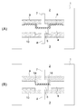
- FIG. 1 is a schematic cross-sectional view showing an airtight connector according to an embodiment of the present invention.
- the connector base 1 of the insulator is molded of, for example, a polyester-based liquid crystal polymer (LCP), and has a partition wall portion 4 that separates the first space 2 and the second space 3.
- LCP liquid crystal polymer
- an appropriate filler can be added in order to improve the mechanical properties of the liquid crystal polymer (LCP).
- One space is, for example, a vacuum, pressure, liquid, gas environment, etc., and electronic components are stored in the other space.
- Airtight connectors are used in many industrial fields such as air conditioner compressors, gas sensors, flow rate sensors, and medical sensors, in addition to aerospace, defense, and security.
- the outer shape of the connector base 1 has a shape such as a substantially cylindrical shape or a substantially rectangular parallelepiped, depending on the use of these airtight connectors.
- the partition wall portion 4 is provided with a hole 5, and a conductive plated portion 6 such as copper having a thickness of about 25 ⁇ m is formed to cover the hole 5 and its periphery. In this example, the plated portion 6 is formed over almost the entire surface of the partition wall portion 4.
- Pins 7 are brazed to one surface of the portion of the plated portion 6 that covers the holes 5, and pins 8 are brazed to the other surface.
- Pins 7 and 8 are members for electrical connection in which the surface of the base such as pure copper, brass, and phosphor bronze is plated with gold or tin. Brazing is performed by soldering, silver brazing, gold-tin (AuSn) bonding by radio frequency induction heating (IH), or the like. If the LCP material leaks, epoxy resin, epoxy or acrylic resin impregnated sealing portions 9 and 10 may be provided.
- the airtight connector according to the present embodiment has a structure in which the airtightness is maintained and the electrical connection is performed by the plated portion 6.
- the plated portion 6 is formed so as to cover the hole 5 and its periphery, the contact area between the partition wall portion 4 and the plated portion 6 becomes large, so that the plated portion is formed when a force is applied to the pins 7 and 8. 6 is less likely to be peeled off from the partition wall portion 4, and the breaking strength of the airtight connector is improved.
- the plated portion 6 is an integral or single member with respect to the entire portion that is in close contact with the partition wall portion 4 and covers the hole 5. Even when a plated portion having an increased thickness is formed by stacking electroless plating and electroplating, it is an integral or single member.
- FIG. 1B shows a modified example of the airtight connector shown in FIG. 1A.
- a plated portion 16 covering the hole 5 is provided in the recess 14 of the partition wall portion 4.
- the plated portion 16 is an integral or single member with respect to the entire portion that is in close contact with the recess 14 and covers the hole 5. Even when a plated portion having an increased thickness is formed by stacking electroless plating and electroplating, it is an integral or single member.
- the hole 5 that communicates the first space 2 and the second space 3 can be closed, and leakage can be reliably prevented.
- a synthetic resin such as LCP (liquid crystal polymer), PPA, PA, or thermosetting resin or ceramic is molded to form a connector base 1 having holes 5.
- a base material made of an inorganic material such as ceramic or glass can be used in addition to a synthetic resin such as a thermoplastic resin or a thermosetting resin.
- aromatic liquid crystal polymers polysulfones, polyetherpolysulfones, polyarylsulfones, polyetherimides, polyesters, acrylonitrile-butadiene-styrene copolymer resins, polyamides, modified polyphenylene oxide resins, norbornene resins, phenolic resins, epoxy resins, Polyphenylene sulfide resin (PPS) resin, polybutylene terephthalate (PBT) resin and the like.
- PPS Polyphenylene sulfide resin
- PBT polybutylene terephthalate
- a polyester-based liquid crystal polymer having heat resistance and a coefficient of thermal expansion close to that of a metal under a wide temperature condition, having elasticity equivalent to that of a metal film, and having excellent properties equivalent to those of a metal film in a thermal cycle test.
- the filler glass fiber, calcium pyrophosphate, wallastonite, calcium carbonate, barium titanate, carbon fiber, quartz fiber, barium sulfate and the like may be added.
- the exposed surface of the partition wall portion 4 of the liquid crystal polymer (LCP) is roughened by etching.
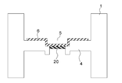
- an acrylonitrile-butadiene-styrene (ABS) resin, a biodegradable resin, or the like is used to form the molded body 20 so as to close the pores 5.
- ABS acrylonitrile-butadiene-styrene
- a biodegradable resin, or the like is used to form the molded body 20 so as to close the pores 5.
- the material of the connector base 1 a material that is difficult to dissolve in an organic solvent or the like for dissolving the molded product 20 is selected.
- the exposed surfaces 21 and 22 are roughened with a chromic acid or potassium hydroxide (KOH) solution or the like.
- a known etching method can be applied.
- the dry method can be performed, for example, by irradiating plasma or using a gas.
- an aqueous solution of an alkali metal hydroxide such as NaOH or KOH, an aqueous solution of an alkali metal alcoholate such as alcoholic sodium or alcoholic potassium, or an organic solvent such as dimethylformamide is used, and these etching solutions are used as a substrate. It can be applied to the surface or contacted by immersing the substrate in these liquids.
- the method using an aqueous solution of NaOH, KOH or the like is preferably under the conditions of a concentration of about 35 to 45 wt% and a temperature of about 70 to 95 ° C.
- a method using an aqueous solution of alkali metal alcoholate or an organic solvent such as dimethylformamide is suitable for roughening after coating with a water-soluble or hydrolyzable polymer material.
- an organic solvent When an organic solvent is used, it may only swell the substrate and not roughen it.
- the acid or alkali treatment may be applied after the treatment with the organic solvent.
- a masking molding step for patterning is performed.
- a mask layer 23 made of polylactic acid (PLA) resin or the like is formed on the surfaces of the connector base 1 and the molded body 20 other than the portion where the plated portion 6 is formed, as shown in FIG.
- the exposed surface 21 of the partition wall 4 and the exposed surface 22 of the molded body 20 are exposed to Pd, Pt, etc. by immersing them in an accelerator solution such as sulfuric acid, hydrochloric acid, sodium hydroxide, or ammonium. Apply catalyst.
- an accelerator solution such as sulfuric acid, hydrochloric acid, sodium hydroxide, or ammonium.
- the plating catalyst known catalysts can be used, and among them, those containing Pd and Pt are preferable, and these are used as, for example, inorganic salts such as chloride.
- the plating catalyst is applied by adhering the above-mentioned inorganic salt to the substrate and then precipitating the above-mentioned catalyst metal by an accelerator treatment.
- the solution of the inorganic salt and the substrate may be brought into contact with each other. For example, the substrate is immersed in the solution of the inorganic salt, or the aqueous solution is applied to the substrate. ..
- the coating material made of the above-mentioned water-soluble or hydrolyzable polymer material such as methanol, ethanol and isopropyl alcohol is not completely eluted (1).
- the part may be eluted)
- Organic solvent can also be used.
- the mask layer 23 of the PLA resin is dissolved in the accelerator step.
- the exposed surfaces 21 and 22 are electrolessly plated with copper (Cu) to form the plated portion 6 as shown in FIG. Further, electroplating of Cu, Au or the like can be added.
- a known metallizing method electroless plating method or electroplating method
- the plated metal include copper, nickel, gold, and various other metals.
- the plating process can be divided into a large number of times.
- a pre-plating step may be provided after the catalyst applying step.
- Pre-plating can also be performed by a known metallizing method, preferably an electroless plating method, and the plating metal can be the same as the metal in the so-called main plating step described above.
- the plating quality in the main plating process can be further improved. It is also possible to provide a post-plating process.
- the post-plating step can also be performed by a known metallizing method, preferably an electroless plating method, and the plating metal may be the same type as the metal in the main plating step, but may be different. May be good.
- electroless plating is performed and then electroplating is performed to form the plated portion 6 thickly.
- the molded body 20 is removed with an organic solvent or the like, the oxide film is removed, the plating film is further thickened, and both surfaces of the portion corresponding to the hole 5 of the plating portion 6 are shown in FIG. As described above, the pins 7 and 8 are joined by the solder 40, respectively.
- sealing portions 9 and 10 such as epoxy resin are provided to manufacture an airtight connector having the configuration shown in FIG.
- the exposed surface 21 of the partition wall portion 4 is roughened by etching, and for example, electroless plating and electroplating are applied to the plated portion 6
- the plated portion 6 is securely fixed to the surface of the partition wall portion 4, and the bonding area between the plated portion 6 and the partition wall portion 4 becomes large. Therefore, when a force is applied to the pin, the plated portion 6 is formed. Is less likely to come off from the partition 4 and the breaking strength of the airtight connector is improved.
- the forming range of the mask layer for patterning and the forming range of the plated portion are different from those of the airtight connector shown in FIG. The process is the same. In the airtight connector manufactured in this way, by covering the hole 5 with the plated portion 16, the hole 5 communicating the first space 2 and the second space 3 can be closed, and leakage can be reliably prevented. ..
- one pin 50 has a flange portion 51, and the flange portion 51 is silver brazed, soldered, and AuSn joined to the plated portion 6. It can be joined by joining with or the like to ensure adhesion to the plated portion 6 and to be strong against external force.
- the shape is different from that of the plated portion 6 of FIG. 1 according to the shape of the joined portion of the parts 61 and 62 to be joined.
- the shape of the plating portion 63 is changed.
- the central portion of the plating portion 63 is curved in a substantially hemispherical shape. Even with such a shape, leakage in the airtight connector can be reliably prevented.
- a hole 72 is provided in the partition wall portion 71 of the connector base portion 70.
- a molded body 73 that closes the hole 72 is formed.
- a substantially hemispherical recess is provided on the exposed surface of the molded body 73.
- the surfaces of the connector base 70 and the molded body 73 other than the portion where the plated portion 63 is formed are covered with the mask layer 74 of polylactic acid (PLA) resin.
- a catalyst for plating is applied. At this time, the mask layer 74 is dissolved.
- the mask layer 74 is dissolved and removed before the molded body 73 is dissolved and removed.
- the selected surfaces of the connector base 70 and the molded body 73 are etched and roughened.
- electroless plating and electroplating are performed to form the plated portion 63.
- the molded body 73 is removed to obtain a plated portion 63 firmly bonded to the surface of the partition wall portion 71 as shown in FIG.
- electroplating is further performed to further increase the plating film thickness. It is also possible to form the molded body 73 after etching the partition wall portion 71, but in this case, only the molded body 73 is etched. For example, if chromic acid or the like is used, only the ABS resin molded body 73 is etched. At this time, the connector base 70 of the LCP is not etched.
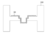
- the airtight connector according to the fourth embodiment of the present invention has a plated portion 90 having a shape suitable for connecting parts having a rectangular cross section.
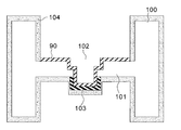
- a partition wall 101 having a hole 102 is formed as the connector base 100.
- a molded body 103 having a rectangular cross section is formed in the vicinity of the hole 102.
- a mask layer 104 for patterning is formed on the surface of the connector base 100 and the surface of the molded body 103 other than the portion forming the plated portion 90 with polylactic acid (PLA) resin or the like.
- PLA polylactic acid
- a plating catalyst is applied, and a thick-coated plated portion 90 is formed by electroless plating and electroplating.
- the mask layer 104 is dissolved and removed when the catalyst is applied.
- the molded body 103 is removed to obtain a plated portion 90 that is securely adhered to the surface of the partition wall portion 101 as shown in FIG. By performing electroplating even after the molded body 103 is dissolved and removed, a plated portion 90 having a thicker film can be obtained.
- the same material as that used for forming the plated portion 6 according to the first embodiment is used. Further, it is possible to form a plated portion having a desired shape other than the shape shown in the above-described embodiment, depending on the parts accommodated in the airtight connector.
- the airtight connector according to the present embodiment is an example of an airtight coaxial connector having a coaxial structure suitable for transmission of a high frequency signal.
- the connector base 110 of the insulator has an outer partition 111, an intermediate partition 112, and an inner partition 113, and a hole 114 is provided in the center.
- a plated portion 115 for connecting to an outer conductor of a coaxial cable (not shown) is provided on the outer wall portion of the connector base 110 and the surface of the outer partition wall 111.
- the plated portion 115 is grounded at any suitable location to provide an electrostatic shield.
- a plated portion 116 is provided in a part of the inner partition portion 113 of the hole 114 and its peripheral portion. The plated portion 115 and the plated portion 116 are electrically insulated by the intermediate partition wall portion 112 and the inner partition wall portion 113 of the insulator.
- Pins 117 and 118 are joined to both sides of the plated portion 116 of the portion covering the hole 114, respectively, and for example, one pin is connected to a female contact pin or an internal conductor of a coaxial cable integrated with a connector base. It has become like. Further, the airtight connector of the present invention is not limited to this, and the high-speed signal line integrated with the female contact pin or the connector base, the inner center conductor of the coaxial connector in addition to the connector alone, is integrated with the circuit of the circuit board. It is also applicable to the structure.
- a synthetic resin such as LCP (liquid crystal polymer), PPA, PA, or thermosetting resin or ceramic is molded to have an outer partition wall 111, an intermediate partition wall 112, an inner partition wall 113, and a hole 114.
- the connector base 110 is formed.
- the first molded body 120 is formed by using ABS resin or the like so as to straddle the outer partition wall portion 111 and the intermediate partition wall portion 112. Further, ABS resin or the like is used to form the second molded body 121 that closes the hole 114.
- a mask layer such as polylactic acid (PLA) resin for patterning is formed on the surface of the connector base 110 and the surfaces of the first molded body 120 and the second molded body 121 other than the portions where the plated portions 115 and 116 are formed.
- Form 124 is formed.
- etching is performed to roughen the surface.
- a plating catalyst is applied, and the plated portions 115 and 116 are formed by electroless plating and electroplating.
- the mask layer 124 is dissolved and removed when the catalyst is applied.
- the first molded body 120 and the second molded body 121 are removed to ensure that the outer wall portion of the connector base 110, the outer partition wall portion 111, a part of the intermediate partition wall portion 112, and the surface of the inner partition wall portion 113 are surfaced.
- the bonded plated portions 115 and 116 are obtained.
- the plating portion 115 and the plating portion 116 are electrically insulated, and the outer conductor and the inner conductor of the coaxial connector are respectively.
- the airtight coaxial connector according to the fifth embodiment shown in FIG. 11 can be manufactured by the same method as the manufacturing method described for the airtight connector according to the first embodiment shown in FIGS. 1 to 4. Also in this embodiment, the exposed surfaces of the outer partition wall 111, the intermediate partition wall 112, and the inner partition wall 113 are roughened by etching, and electroless plating is performed to form the plated portions 115 and 116. The plated portions 115 and 116 are securely fixed to the surfaces of these members, and the bonding area between the plated portions 115 and 116 and the outer partition wall 111, the intermediate partition wall 112 and the inner partition wall 113 is also large. Leakage in the holes 114 and the bulkhead is reliably prevented.
- the impedance adjustment can be performed as follows.
- the characteristic impedance can be adjusted by setting the length D of the pin 117, the length E of the pin 118, and the size F of the gap provided in the intermediate partition wall portion 112 to appropriate values. Since the dielectric constant of a synthetic resin such as an LCP material is significantly different from that of vacuum or air, it is effective to adjust the size F of the voids provided in the intermediate partition wall portion 112 for adjusting the characteristic impedance. It should be noted that the characteristic impedance can be adjusted by changing the dimensions of parts other than those described above.
- the airtight connector according to the embodiment described above can be used for various purposes regardless of its dimensions.
- the airtight coaxial connector shown in FIG. 11 can be suitably used for a smartphone compatible with the 5G communication standard and a high-frequency circuit board in which the coaxial connector (which becomes the central conductor circuit board) is integrated.
- the airtight connector according to the embodiment of the present invention, a structure that reliably prevents leaks can be realized at low cost without requiring complicated adjustment.
- an airtight coaxial connector structure that allows easy impedance adjustment can be realized, and a circuit board and coaxial connector integrated structure that eliminates the connection of the coaxial connector with solder or the like can also be realized.
Landscapes
- Engineering & Computer Science (AREA)
- Manufacturing & Machinery (AREA)
- Connections Arranged To Contact A Plurality Of Conductors (AREA)
- Connector Housings Or Holding Contact Members (AREA)
- Coupling Device And Connection With Printed Circuit (AREA)
Priority Applications (2)
| Application Number | Priority Date | Filing Date | Title |
|---|---|---|---|
| JP2021524946A JP7625270B2 (ja) | 2019-06-07 | 2020-06-08 | 気密コネクタ |
| US17/616,846 US11967796B2 (en) | 2019-06-07 | 2020-06-08 | Hermetic connector |
Applications Claiming Priority (2)
| Application Number | Priority Date | Filing Date | Title |
|---|---|---|---|
| JP2019107339 | 2019-06-07 | ||
| JP2019-107339 | 2019-06-07 |
Publications (1)
| Publication Number | Publication Date |
|---|---|
| WO2020246614A1 true WO2020246614A1 (ja) | 2020-12-10 |
Family
ID=73652563
Family Applications (1)
| Application Number | Title | Priority Date | Filing Date |
|---|---|---|---|
| PCT/JP2020/022507 Ceased WO2020246614A1 (ja) | 2019-06-07 | 2020-06-08 | 気密コネクタ |
Country Status (3)
| Country | Link |
|---|---|
| US (1) | US11967796B2 (https=) |
| JP (1) | JP7625270B2 (https=) |
| WO (1) | WO2020246614A1 (https=) |
Citations (4)
| Publication number | Priority date | Publication date | Assignee | Title |
|---|---|---|---|---|
| US4231631A (en) * | 1978-01-18 | 1980-11-04 | Saft-Societe Des Accumulateurs Fixes Et De Traction | Through-connector providing an electrical connection through a single or double plastic wall and application thereof to an electrical battery |
| JPS5758702Y2 (https=) * | 1978-07-07 | 1982-12-15 | ||
| JPS614368U (ja) * | 1984-06-15 | 1986-01-11 | 株式会社東芝 | 接続装置 |
| JP2004087246A (ja) * | 2002-08-26 | 2004-03-18 | Kyocera Corp | 電流導入端子 |
Family Cites Families (9)
| Publication number | Priority date | Publication date | Assignee | Title |
|---|---|---|---|---|
| US4174145A (en) * | 1976-12-29 | 1979-11-13 | The United States Of America As Represented By The United States Department Of Energy | High pressure electrical insulated feed thru connector |
| US4913673A (en) * | 1988-07-29 | 1990-04-03 | Amp Incorporated | Hermetically sealed connector |
| JP2687149B2 (ja) * | 1988-10-15 | 1997-12-08 | 三共化成株式会社 | 金属膜と絶縁体とインサート部材の接続方法 |
| US5109594A (en) * | 1990-11-01 | 1992-05-05 | Explosive Fabricators, Inc. | Method of making a sealed transition joint |
| US6844502B2 (en) * | 2002-05-16 | 2005-01-18 | Emerson Electric Co. | Hermetically sealed current conducting terminal assembly |
| JP2006040766A (ja) | 2004-07-28 | 2006-02-09 | Kyocera Corp | 気密端子 |
| JP2013089313A (ja) | 2011-10-13 | 2013-05-13 | Tyco Electronics Japan Kk | コネクタ |
| JP6208935B2 (ja) | 2012-10-31 | 2017-10-04 | タイコエレクトロニクスジャパン合同会社 | コネクタ |
| JP2014207145A (ja) | 2013-04-12 | 2014-10-30 | タイコエレクトロニクスジャパン合同会社 | 平板状コネクタおよび隔壁実装構造 |
-
2020
- 2020-06-08 JP JP2021524946A patent/JP7625270B2/ja active Active
- 2020-06-08 US US17/616,846 patent/US11967796B2/en active Active
- 2020-06-08 WO PCT/JP2020/022507 patent/WO2020246614A1/ja not_active Ceased
Patent Citations (4)
| Publication number | Priority date | Publication date | Assignee | Title |
|---|---|---|---|---|
| US4231631A (en) * | 1978-01-18 | 1980-11-04 | Saft-Societe Des Accumulateurs Fixes Et De Traction | Through-connector providing an electrical connection through a single or double plastic wall and application thereof to an electrical battery |
| JPS5758702Y2 (https=) * | 1978-07-07 | 1982-12-15 | ||
| JPS614368U (ja) * | 1984-06-15 | 1986-01-11 | 株式会社東芝 | 接続装置 |
| JP2004087246A (ja) * | 2002-08-26 | 2004-03-18 | Kyocera Corp | 電流導入端子 |
Also Published As
| Publication number | Publication date |
|---|---|
| JPWO2020246614A1 (https=) | 2020-12-10 |
| JP7625270B2 (ja) | 2025-02-03 |
| US20220311158A1 (en) | 2022-09-29 |
| US11967796B2 (en) | 2024-04-23 |
Similar Documents
| Publication | Publication Date | Title |
|---|---|---|
| CN213280231U (zh) | 埋入式电路板、移动设备以及传感组件 | |
| CN107022747A (zh) | 微波介质部件及其制造方法 | |
| CN102342187A (zh) | 覆盖膜及其制造方法以及柔性印刷布线板 | |
| WO2016208090A1 (ja) | 立体配線基板の製造方法、立体配線基板、立体配線基板用基材 | |
| CN110169215B (zh) | 具有可挠性端子的电子组件 | |
| CN103906360A (zh) | 柔性电路板及其制作方法 | |
| CN103985943A (zh) | 双电容耦合同轴电缆到空气微带的转接装置 | |
| JP7625270B2 (ja) | 気密コネクタ | |
| JP2020005018A (ja) | 差動伝送線路、配線基板および半導体用パッケージ | |
| CN101288138A (zh) | 电子部件和用于电子部件的引脚单元 | |
| CN101479816A (zh) | 用于容纳电子部件的壳体和电子部件装置 | |
| JP4875595B2 (ja) | 導電回路を有する合成樹脂製のばね | |
| CN204558714U (zh) | 一种金属钎焊封接型气密电连接器 | |
| US11942744B2 (en) | Method for producing a high-frequency connector and associated apparatus | |
| CN112436347A (zh) | 一种直立式接pcb的射频连接器 | |
| WO2021125164A1 (ja) | 気密コネクタおよびその製造方法 | |
| KR100401340B1 (ko) | Pcb용 전해동박의 표면처리방법 | |
| JP6014792B1 (ja) | 立体配線基板の製造方法、立体配線基板、立体配線基板用基材 | |
| CN114830442B (zh) | 气密连接器及其制造方法 | |
| CN110784987A (zh) | 自由接地膜、线路板及自由接地膜的制备方法 | |
| CN114267953B (zh) | 一种碳纤维脊喇叭天线单元及其制造方法 | |
| CN113921285A (zh) | 固体电解电容器 | |
| JP3628238B2 (ja) | 配線基板およびその導波管との接続構造 | |
| KR100907523B1 (ko) | 솔더링이 가능한 전기적 접속부재 | |
| JP2022039457A (ja) | 回路基板及びその製造方法 |
Legal Events
| Date | Code | Title | Description |
|---|---|---|---|
| 121 | Ep: the epo has been informed by wipo that ep was designated in this application |
Ref document number: 20817967 Country of ref document: EP Kind code of ref document: A1 |
|
| ENP | Entry into the national phase |
Ref document number: 2021524946 Country of ref document: JP Kind code of ref document: A |
|
| NENP | Non-entry into the national phase |
Ref country code: DE |
|
| 122 | Ep: pct application non-entry in european phase |
Ref document number: 20817967 Country of ref document: EP Kind code of ref document: A1 |