WO2020246390A1 - 浮遊炉用部材、浮遊炉及び光学ガラスの製造方法 - Google Patents
浮遊炉用部材、浮遊炉及び光学ガラスの製造方法 Download PDFInfo
- Publication number
- WO2020246390A1 WO2020246390A1 PCT/JP2020/021378 JP2020021378W WO2020246390A1 WO 2020246390 A1 WO2020246390 A1 WO 2020246390A1 JP 2020021378 W JP2020021378 W JP 2020021378W WO 2020246390 A1 WO2020246390 A1 WO 2020246390A1
- Authority
- WO
- WIPO (PCT)
- Prior art keywords
- floating furnace
- gas
- radius
- recess
- floating
- Prior art date
- Legal status (The legal status is an assumption and is not a legal conclusion. Google has not performed a legal analysis and makes no representation as to the accuracy of the status listed.)
- Ceased
Links
Images



Classifications
-
- C—CHEMISTRY; METALLURGY
- C03—GLASS; MINERAL OR SLAG WOOL
- C03B—MANUFACTURE, SHAPING, OR SUPPLEMENTARY PROCESSES
- C03B19/00—Other methods of shaping glass
- C03B19/02—Other methods of shaping glass by casting molten glass, e.g. injection moulding
-
- C—CHEMISTRY; METALLURGY
- C03—GLASS; MINERAL OR SLAG WOOL
- C03B—MANUFACTURE, SHAPING, OR SUPPLEMENTARY PROCESSES
- C03B19/00—Other methods of shaping glass
- C03B19/10—Forming beads
-
- C—CHEMISTRY; METALLURGY
- C03—GLASS; MINERAL OR SLAG WOOL
- C03B—MANUFACTURE, SHAPING, OR SUPPLEMENTARY PROCESSES
- C03B5/00—Melting in furnaces; Furnaces so far as specially adapted for glass manufacture
- C03B5/16—Special features of the melting process; Auxiliary means specially adapted for glass-melting furnaces
- C03B5/235—Heating the glass
-
- C—CHEMISTRY; METALLURGY
- C03—GLASS; MINERAL OR SLAG WOOL
- C03B—MANUFACTURE, SHAPING, OR SUPPLEMENTARY PROCESSES
- C03B5/00—Melting in furnaces; Furnaces so far as specially adapted for glass manufacture
- C03B5/16—Special features of the melting process; Auxiliary means specially adapted for glass-melting furnaces
- C03B5/42—Details of construction of furnace walls, e.g. to prevent corrosion; Use of materials for furnace walls
- C03B5/43—Use of materials for furnace walls, e.g. fire-bricks
Definitions
- the present invention relates to a member for a floating furnace, a floating furnace using the member, and a method for manufacturing optical glass.
- the present invention claims the priority of application number 2019-1006097 of the Japanese patent filed on June 6, 2019, and for designated countries that are permitted to be incorporated by reference to the literature, the content described in the application is Incorporated into this application by reference.
- Patent Document 1 discloses a method for manufacturing optical glass using a laser floating furnace. In such a laser floating furnace, it is required to stably float a glass sample with a floating gas.
- a first aspect of the present invention is a member for a floating furnace used in a gas floating furnace, which comprises a first surface having a recess and a second surface opposite to the first surface.
- the second surface has a gas introduction portion into which gas is introduced, and the recess of the first surface has a gas injection portion provided in the central portion and a gas injection portion provided in the peripheral portion.
- the second aspect of the present invention is a floating furnace including the above-mentioned members for a floating furnace.
- gas is blown onto the sample from the gas injection portion of the floating furnace member described above to suspend the sample, and the suspended sample is irradiated with a laser beam to melt the sample.
- This is a method for producing an optical glass, which includes a step of causing the sample to be cooled and a step of cooling the molten sample.
- FIG. 1 is a schematic view of a manufacturing apparatus including a floating furnace including a member for a floating furnace according to the present embodiment.
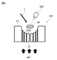
- FIG. 2 is a schematic view showing a state in which the sample suspended on the floating furnace member in FIG. 1 is heated.
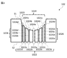
- FIG. 3 is a schematic view of a member for a floating furnace according to the present embodiment.
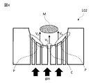
- FIG. 4 is a schematic view for explaining the flow velocity of the gas in the member for the floating furnace according to the present embodiment.
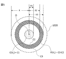
- FIG. 5 is a partial schematic view of a recess of the floating furnace member according to the present embodiment.
- FIG. 6 is a schematic view for explaining the shape of the concave portion of the floating furnace member according to the present embodiment.
- FIG. 7 is a schematic view showing another example of the floating furnace member according to the present embodiment.
- FIG. 8 is a schematic view showing still another example of the member for a floating furnace according to the present embodiment.
- FIG. 9 is a schematic view showing still another example of the member for a floating furnace according to the present embodiment.
- FIG. 10 is a schematic view provided for explaining the members for a floating furnace used in each comparative example.
- FIG. 11 is a graph in which the optical constant values of each example and each comparative example are plotted.
- the present embodiment an embodiment of the present invention (hereinafter, referred to as “the present embodiment”) will be described.
- the following embodiments are examples for explaining the present invention, and are not intended to limit the present invention to the following contents.
- FIG. 1 is a schematic view of a manufacturing apparatus provided with a floating furnace including a floating furnace member according to the present embodiment
- FIG. 2 shows a state in which a sample suspended on the floating furnace member is heated in FIG.
- FIG. 3 is a schematic diagram of a member for a floating furnace according to this embodiment.
- the manufacturing apparatus 1 is an optical glass manufacturing apparatus provided with a gas jet type floating furnace, and is a floating furnace including a floating furnace member 102 that blows gas onto the sample M to float the sample M, and a laser beam L on the floating sample M.
- the laser light source 103 that irradiates the gas
- the radiation thermometer 106 that measures the temperature of the suspended sample M
- the computer 107 that controls the output of the laser light source 103 based on the temperature information of the radiation thermometer 106
- a gas flow rate controller 110 for adjusting the flow rate of the supplied gas is provided.
- the sample M floating above the floating furnace member 102 arranged on the stage 101 is non-contact heated by irradiation with the laser beam L.
- the sample M melts and becomes a substantially spherical or substantially ellipsoidal melt due to its own surface tension, and floats in that state.
- the sample M solidifies when cooled to become optical glass.
- Non-contact heating of the sample M is performed by irradiating the sample M with the laser light L emitted from the laser light source 103 via the mirror 104 and the mirror 105.
- the temperature of the sample M heated by the irradiation of the laser beam L is monitored by the radiation thermometer 106.
- the output of the laser light source 103 is controlled by the computer 107 based on the temperature information of the sample M monitored by the radiation thermometer 106. Further, the state of the sample M is imaged by the CCD camera 108, and the state is output to the monitor 109.
- the laser light source is not particularly limited, and examples thereof include a carbon dioxide gas laser, a semiconductor laser, a fiber laser, and a YAG laser.
- the flow rate of the gas sent to the floating furnace member 102 is controlled by the gas flow rate controller 110.
- the type of gas is not particularly limited, and a known gas can be appropriately adopted. Specific examples thereof include oxygen, carbon dioxide, nitrogen, argon, and air. Further, the shape of the nozzle (not shown) connected to the floating furnace member 102 is not particularly limited, and a known method can be appropriately adopted.
- the floating furnace member 102 includes a first surface S1 having a recess 1020 facing the sample M and a second surface S2 opposite to the first surface S1, and the second surface S2 is
- the recess 1020 of the first surface S1 has a gas injection unit 1024 for injecting gas.
- the gas injection unit 1024 is composed of a gas injection unit 1024a provided in the central portion C of the first surface S1 and gas injection portions 1024b, c, d provided in the peripheral portion P.
- the number, shape, and arrangement of the gas injection units 1024 are not particularly limited, and suitable conditions can be appropriately selected.
- FIG. 4 is a schematic diagram provided for explaining the flow velocity of gas in the member for a floating furnace according to the present embodiment.
- the sample M is stably suspended near the irradiation target position of the laser beam L (stable floating). ) Can be done.
- the high stable floating property contributes to irradiation heating with a precise laser beam, an increase in the size of the obtained optical glass (glass gob), and a uniform composition of components.
- the floating furnace member 102 preferably satisfies the relationship represented by the following formula (2). 0.1 ⁇ V C / V P ⁇ 1 ⁇ (2)
- the sample M can be suspended more stably.
- a network of SiO 2 , B 2 O 3 , P 2 O 5 , GeO 2 or the like is formed. It was necessary to increase the glass forming ability by adding a large amount of oxide. Therefore, when the glass composition contains a large amount of a material other than the network-forming oxide and the content of the network-forming oxide is small as described above, crystallization (non-uniform nucleation) starts from the container-melt interface. There is a problem that vitrification is difficult due to the occurrence of.
- the floating furnace member 102 by using the floating furnace member 102 according to the present embodiment, the conditions for blowing the gas onto the sample M can be controlled with high accuracy. As a result, a stable floating state that could not be achieved in the past can be maintained (high floating stability), and a larger glass gob can be produced.
- a glass gob is sometimes used as a material for an optical lens of various optical devices, and it is desired that a large glass gob can be stably produced. Such a requirement can be met by using the floating furnace member according to the present embodiment.
- FIG. 5 is a partial schematic view of a recess of the floating furnace member according to the present embodiment.
- the recess 1020 is circular.
- the circle with radius R1 from the center point O of the circle is the first circle C1
- the circle with radius R2 is the second circle C2
- the circle with radius R3 is the third circle C3.
- the "center point” is the center point of the recess 1020 in the top view.
- the shape of the recess 1020 of the first surface S1 viewed from the top is a circular shape
- the center of the circle when the shape viewed from above is an elliptical shape or a polygonal shape such as a rectangular shape, it means the center of gravity.
- the recess 1020 is formed from the region of the first circle C1, the region of the second circle C2 having a radius R2 equal to or greater than the radius R1 of the first circle, and the radius R2 of the second circle C2 in the top view.
- the central portion C is the region of the first circle C1
- the peripheral portion P is from the region of the third circle C3. It is an annular region excluding the region of the second circle C2.
- the central portion C preferably has a radius R1 from the central point O of 2 mm or less in the top view of the concave portion 1020.
- the radius R1 is preferably 1 to 2 mm.
- the peripheral portion P preferably has a radius R2 corresponding to the inner peripheral radius of the annular region of 2 to 4 mm, and a radius R3 corresponding to the outer peripheral radius of the annular region of 4.5 to. It is preferably 9 mm. Further, the radius R2 is preferably 1 to 3 times the radius R1, and the radius R3 is preferably 3.5 to 6 times the radius R1.
- the recess 1020 has a circular shape with a radius R in top view.
- the central portion C is preferably a circular region in which the radius R1 from the center point O is 0.2R (0.2 times the radius R) or less with respect to the radius R of the concave portion 1020 in the top view of the concave portion 1020.
- the peripheral portion P preferably has a radius R2 from the center point of 0.4R (0.4 times the radius R) or more with respect to the radius R of the recess 1020, and is from the center point.
- the radius R3 is preferably 0.9 R (0.9 times the radius R) or less.
- peripheral portion P may be outside the central portion C, and may or may not be adjacent to the central portion C. From the viewpoint of obtaining higher floating stability, it is preferable that the peripheral portion P is not adjacent to the central portion C as shown in FIG.
- the floating furnace member 102 preferably includes a through hole 1026 that communicates the gas introduction unit 1022 and the gas injection unit 1024. Through the through hole 1026, the gas supplied from the gas introduction unit 1022 provided on the second surface S2 is efficiently sent toward the gas injection unit 1024 provided on the recess 1020 of the first surface S1.
- Through holes 1026c and through holes 1026d that communicate the gas introduction section 1022d and the gas injection section 1024d are formed, respectively.
- all the gas introduction parts 1022 and all the gas injection parts 1024 may not be communicated by the through holes 1026, and only a part of them may be communicated by the through holes 1026.
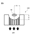
- FIG. 6 is a schematic view provided for explaining the shape of the recess of the floating furnace member according to the present embodiment.
- the radius R of the recess 1020 is preferably 5 to 10 mm.
- the lower limit of the radius R of the recess 1020 is more preferably 5.5 mm, and even more preferably 6.5 mm.
- the upper limit of the radius R of the recess 1020 is more preferably 9.5 mm, and even more preferably 8.5 mm.
- the case where the concave portion 1020 of the first surface S1 is viewed from above is circular, but the present invention is not limited to this.
- the shape of the recess 1020 of the first surface S1 when viewed from above may be an elliptical shape or a polygonal shape such as a rectangular shape. If it is not a perfect circle, the "radius" shall mean the shortest diameter from the center point.
- the maximum depth H of the recess 1020 is preferably 4 to 7 mm.
- the maximum depth H of the recess 1020 here means the distance from the opening of the recess 1020 to the deepest part of the recess 1020.
- the lower limit of the maximum depth H of the recess 1020 is more preferably 5 mm, and even more preferably 5.5 mm.
- the upper limit of the maximum depth H of the recess 1020 is more preferably 6.5 mm, and even more preferably 6 mm.
- the shape of the recess 1020 in cross section is not particularly limited, but is preferably semicircular or semi-elliptical from the viewpoint of more stably floating the sample M.
- the material of the floating furnace member 102 is not particularly limited, but at least a part or all of the members are stainless steel (SUS), silicon carbide (SiC), alumina (Al 2 O 3 ), zirconia (ZrO 2 ), duralumin. , Copper (Cu), and carbon (C), preferably at least one selected from the group. Since these materials are excellent in heat impact resistance and wear resistance even at high temperatures, gas can be sprayed on the sample M with higher accuracy even at high temperatures where laser light heating is performed. , Sample M can be stably suspended.
- through holes 1026 for passing the gas inside the floating furnace member 102 are arranged in the vertical direction (see FIG. 3), but the arrangement intervals are made dense.
- the through holes are arranged so as to be sparsely arranged near the center point O of the recess 1020, and the through holes are arranged closer to the end of the recess 1020. It can be arranged so as to be.
- the floating furnace member 102 in which the through holes for passing gas are provided along the vertical direction inside the member has been described as an example, but the floating furnace member according to the present embodiment is not limited to such an embodiment. Other aspects may be used.
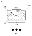
- FIG. 7 is a schematic view showing another example of the floating furnace member according to the present embodiment.
- the floating furnace member 111 is porous.
- the gas supplied to the gas introduction unit 1112 can be sprayed from the gas injection unit 1114 to the sample M via the internal pore structure.
- the above-mentioned through holes may be holes of a material that is porous. That is, the porosity of the floating furnace member 111 can be said to be one aspect of the above-mentioned through hole.
- FIG. 7 illustrates a case where all the members constituting the floating furnace member 111 are porous, but only a part of the members may be porous.
- the porous material include stainless steel (SUS), silicon carbide (SiC), alumina (Al 2 O 3 ), zirconia (ZrO 2 ), carbon (C) and the like.
- gas By making the internal arrangement of the pore structure of the floating furnace member 111 sparse and dense, gas can be blown so as to satisfy the relationship represented by the equation (1).
- the relationship represented by the equation (1) can be satisfied.
- the floating furnace member 111 may satisfy the relationship of the formula (1), and the above-mentioned sparse and dense arrangement of the porous materials is not particularly limited.
- the porosity may be graded from the center point to the end in a cross-sectional view.
- the porosity here is the ratio of the volume of space to the total volume of substances.
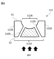
- FIG. 8 is a schematic view showing still another example of the floating furnace member according to the present embodiment.
- the floating furnace member 112 has a gas introduction section 1122 and a gas injection section 1124, and is composed of a porous section 1126 and a non-porous section 1128, and is between the porous section 1126 and the non-porous section 1128.
- a through hole is arranged. That is, the recess 1120 of the first surface S1 has both a porous region and a non-porous region, whereby the gas flow rate can be controlled.
- a non-porous member is used, and for example, stainless steel (SUS), silicon carbide (SiC), alumina, zirconia (ZrO 2 ), duralmine, copper (Cu), carbon (C). ), Other various metals and the like can be used.
- FIG. 9 is a schematic view showing still another example of the floating furnace member according to the present embodiment.
- the shape of the floating furnace member according to the present embodiment is not limited, and a suitable shape can be appropriately adopted in consideration of the apparatus configuration.
- the shape can be determined in consideration of the shape of parts (for example, various gaskets) used when connecting the floating furnace member on the stage 101.
- the side surface S3 of the floating furnace member 113 has a tapered shape.
- a gasket or the like can be interposed on the side surface S3 in order to prevent gas leakage.
- a through hole (not shown) that penetrates the gas injection portion 1134 provided in the recess 1130 of the first surface S1 and the gas introduction portion 1132 provided in the second surface S2 is provided.
- a porous portion may be provided.
- the step of suspending the sample by blowing gas on the sample and melting the sample by laser light irradiation in a gas floating furnace is performed in a chamber capable of depressurizing.
- the gas By blowing the gas onto the sample under reduced pressure, the gas can easily pass through the porosity and through holes of the floating furnace member.
- the gas may be heated, which also suppresses turbulence.
- the laser beam to be irradiated may be defocused or scanned. As a result, the sample can be heated uniformly and the floating stability can be improved.
- ⁇ Manufacturing method> in the method for producing optical glass according to the present embodiment, in a gas floating furnace, gas is blown onto the sample M from the gas injection portion of the floating furnace member described above to suspend the sample M, and the laser beam L is applied to the suspended sample M. It includes a step of melting the sample M by irradiating the sample M and a step of cooling the melted sample M.
- the method for producing optical glass according to the present embodiment by using the above-mentioned member for a floating furnace, there is no contact between the container and the melt (sample M), and heterogeneous nucleation can be suppressed to the maximum. .. Therefore, it is possible to vitrify even a composition having a low or no network-forming oxide content, which cannot be produced by the container method (crucible melting). By adopting such a manufacturing method, it is possible to manufacture an optical glass having a composition system that could not be vitrified in the past. Therefore, it is also possible to manufacture optical glass having a high refractive index and a high Abbe number.
- the diameter is preferably 5 mm or more, more preferably 5.5 mm or more, and further preferably 6 mm or more.
- the optical glass obtained by the manufacturing method according to the present embodiment has many such advantages, it can be applied as a high-bending and low-dispersion glass material or a wide-band transmission material.
- a manufacturing apparatus equipped with a gas jet type floating furnace shown in FIG. 1 was used, and a floating furnace member 113 shown in FIG. 9 was used.
- the structure of the floating furnace member 113 was such that the radius (R) of the recess 1130 was 5.5 mm, the maximum depth (H) of the recess 1130 was 4.5 mm, and the material was a porous body of stainless steel.
- the central portion C of the floating furnace member 113 is a region of 1.1 mm or less from the central point O
- the peripheral portion P is a region of 2.2 to 4.9 mm from the central point O.
- optical glass was produced according to the following procedure.
- raw materials selected from oxides, hydroxides, carbonates, nitrates, sulfates and the like were weighed so as to have a predetermined chemical composition, and then mixed in an alumina dairy pot.
- This raw material was uniaxially pressurized at 20 MPa to form a cylindrical pellet.
- the obtained pellets were fired in an electric furnace at 1000 to 1300 ° C. in the air for 6 to 12 hours to prepare a sintered body.
- the obtained sintered body was roughly crushed, and 500 to 600 mg was collected and installed in a nozzle of a floating furnace member.
- the raw material was melted by irradiating a carbon dioxide laser from above while injecting oxygen gas.
- the melted raw material became spherical or ellipsoidal due to its own surface tension, and was suspended by the pressure of the sprayed gas.
- the raw material was cooled to obtain a glass ball having a diameter of 6 mm.
- no visible volatilization was confirmed during melting, and no bubbles or devitrification were confirmed.
- the refractive index of the glass was measured using a prism coupler (manufactured by Metrocon, model "2010 / M").
- the glass sample was polished, the polished surface was brought into close contact with the single crystal rutile prism, and the total reflection angle when light of the measurement wavelength was incident was measured to determine the refractive index. Measurements were made 5 times each at 3 wavelengths of 473 nm, 594.1 nm, and 656 nm, and the average value was taken as the measured value.
- the obtained measured values were fitted by the least squares method using the following Drude-Voight dispersion formula, and d-line (587.562 nm), F-line (486.133 nm), and C-line (656.
- the refractive index at 273 nm) and the Abbe number ( ⁇ d ) were calculated.
- N Refractive index
- m Electron mass
- c Speed of light
- e Elementary charge
- N Number of molecules per unit volume
- f Oscillator strength
- ⁇ 0 Intrinsic resonance wavelength
- ⁇ Wavelength
- the Abbe number ( ⁇ d ) is defined by the following equation.
- Each table shows the composition and physical property values of each Example and each Comparative Example. Unless otherwise specified, the content of each component is based on cation%.
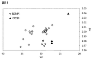
- FIG. 11 is a graph in which the optical constant values of each example and each comparative example are plotted.
- a large glass gob can be stably manufactured, and the obtained optical glass has high refractive index, low dispersibility and devitrification resistance at a high level. Was confirmed.
Landscapes
- Chemical & Material Sciences (AREA)
- Engineering & Computer Science (AREA)
- Materials Engineering (AREA)
- Organic Chemistry (AREA)
- Manufacturing & Machinery (AREA)
- Glass Melting And Manufacturing (AREA)
Abstract
ガス浮遊炉に用いられる浮遊炉用部材であって、凹部1020を有する第一の面S1と、第一の面S1と反対側にある第二の面S2と、を備え、第二の面S2は、ガスが導入されるガス導入部1022を有し、第一の面S1の凹部1020は、中心部Cに設けられたガス噴射部1024aと、周辺部Pに設けられたガス噴射部1024b,c,dと、を有し、中心部Cに設けられたガス噴射部1024aのガスの平均流速(VC)と、周辺部Pに設けられたガス噴射部1024b,c,dのガスの平均流速(VP)とが、下記式(1)で表される関係を満たす、浮遊炉用部材102の提供。 VC<VP ・・・(1)
Description
本発明は、浮遊炉用部材、これを用いた浮遊炉及び光学ガラスの製造方法に関する。本発明は2019年6月6日に出願された日本国特許の出願番号2019-106097の優先権を主張し、文献の参照による織り込みが認められる指定国については、その出願に記載された内容は参照により本出願に織り込まれる。
例えば、特許文献1には、レーザ浮遊炉を用いた光学ガラスの製造方法が開示されている。このようなレーザ浮遊炉においては、ガラス試料を浮遊ガスで安定して浮遊させることが求められている。
本発明の第一の態様は、ガス浮遊炉に用いられる浮遊炉用部材であって、凹部を有する第一の面と、第一の面と反対側にある第二の面と、を備え、第二の面は、ガスが導入されるガス導入部を有し、第一の面の凹部は、中心部に設けられたガス噴射部と、周辺部に設けられたガス噴射部と、を有し、中心部に設けられたガス噴射部のガスの平均流速(VC)と、周辺部に設けられたガス噴射部のガスの平均流速(VP)とが、下記式(1)で表される関係を満たす、浮遊炉用部材である。
Vc<Vp ・・・(1)
Vc<Vp ・・・(1)
本発明の第二の態様は、上述した浮遊炉用部材を含む、浮遊炉である。
本発明の第三の態様は、ガス浮遊炉において、上述した浮遊炉用部材のガス噴射部から試料にガスを吹き付けて試料を浮遊させ、浮遊した試料にレーザ光を照射することによって試料を熔融させる工程と、熔融した試料を冷却させる工程と、を含む、光学ガラスの製造方法である。
以下、本発明の実施形態(以下、「本実施形態」という。)について説明する。以下の本実施形態は、本発明を説明するための例示であり、本発明を以下の内容に限定する趣旨ではない。
なお、図面中、同一要素には同一符号を付すこととし、重複する説明は省略する。また、上下左右等の位置関係は、特に断らない限り、図面に示す位置関係に基づくものとする。更に、図面の寸法比率は図示の比率に限られるものではない。
さらに、本明細書において、「略」を付した用語は、当業者の技術常識の範囲内でその「略」を除いた用語の意味を示すものであり、「略」を除いた意味自体をも含むものとする。そして、その逆も同様である。例えば、「円」という用語は、「略」を付していないが、発明の要旨に反しない限りにおいて、「略円」の意味も当然に包含する。
<浮遊炉用部材、浮遊炉>
図1は、本実施形態に係る浮遊炉用部材を含む浮遊炉を備えた製造装置の模式図であり、図2は、図1において浮遊炉用部材の上で浮遊した試料を加熱する状態を示す模式図であり、図3は、本実施形態に係る浮遊炉用部材の模式図である。
製造装置1は、ガスジェット式の浮遊炉を備えた光学ガラスの製造装置であり、試料Mにガスを吹き付けて浮遊させる浮遊炉用部材102を含む浮遊炉と、浮遊した試料Mにレーザ光Lを照射するレーザ光源103と、浮遊した試料Mの温度を測定する放射温度計106と、放射温度計106の温度情報に基づきレーザ光源103の出力を制御するコンピュータ107と、浮遊炉用部材102に供給するガスの流量を調節するガス流量調節器110と、を備える。
製造装置1では、ステージ101の上に配置された浮遊炉用部材102の上方で浮遊する試料Mを、レーザ光Lの照射により非接触加熱する。これにより、試料Mは熔解して、自身の表面張力によって略球形状又は略楕円体形状の融液となり、その状態で浮遊する。そして、試料Mは、冷却されることで凝固して、光学ガラスとなる。
試料Mの非接触加熱は、レーザ光源103から出射されたレーザ光Lが、ミラー104とミラー105を介して試料Mへ照射されることで行われる。レーザ光Lの照射により加熱される試料Mの温度は、放射温度計106でモニタされる。放射温度計106がモニタする試料Mの温度情報に基づき、レーザ光源103の出力がコンピュータ107によって制御される。また、試料Mの状態はCCDカメラ108によって撮像され、それがモニタ109へ出力される。なお、レーザ光源としては、特に限定されず、例えば、炭酸ガスレーザ、半導体レーザ、ファイバレーザ、YAGレーザ等が挙げられる。
浮遊炉用部材102に送り込まれるガスの流量は、ガス流量調節器110によって制御される。なお、ガスの種類としては、特に限定されず、公知のものを適宜採用することができる。その具体例としては、酸素、二酸化炭素、窒素、アルゴン、空気等が挙げられる。また、浮遊炉用部材102に接続されるノズル(不図示)の形状は特に限定されず、公知の方法を適宜採用することができる。
安定浮遊している試料Mを非接触加熱した後、レーザ光Lを遮断する。これにより融液(試料M)は冷却されて凝固し、光学ガラスが得られる。
浮遊炉用部材102は、試料Mに対向する、凹部1020を有する第一の面S1と、第一の面S1と反対側にある第二の面S2と、を備え、第二の面S2は、ガスが導入されるガス導入部1022を有し、第一の面S1の凹部1020は、ガスを噴射するガス噴射部1024を有する。ガス噴射部1024は、第一の面S1の中心部Cに設けられたガス噴射部1024aと、周辺部Pに設けられたガス噴射部1024b,c,dとから構成される。ガス噴射部1024の数、形状及び配置は特に限定されず、適宜に好適な条件を選択することができる。ガス噴射部1024から試料Mにガスを吹き付けることで、浮遊炉用部材102の上方に試料Mを安定に浮遊させることができる。
図4は、本実施形態に係る浮遊炉用部材におけるガスの流速の説明に供する模式図である。
浮遊炉用部材102は、凹部1020の中心部Cに設けられたガス噴射部1024aから噴射されたガスの平均流速(VC)と、凹部1020の周辺部Pに設けられたガス噴射部1024b,c,dから噴射されたガスの平均流速(VP)とが、下記式(1)で表される関係を満たす。
VC<VP ・・・(1)
VC<VP ・・・(1)
試料Mに吹き付けるガスの流速を、式(1)で表される関係を満たすように制御することで、試料Mをレーザ光Lの照射目標位置付近に安定して浮遊させておくこと(安定浮遊)ができる。高い安定浮遊性は、精密なレーザ光による照射加熱、得られる光学ガラス(ガラスゴブ)の大型化、成分組成の均一化等に資する。
さらに、浮遊炉用部材102は、下記式(2)で表される関係を満たすことが好ましい。
0.1≦VC/VP<1 ・・・(2)
0.1≦VC/VP<1 ・・・(2)
式(2)で表される関係を満たす浮遊炉用部材102を用いることで、より安定して試料Mを浮遊させておくことができる。
従来、例えば、るつぼ等の容器を用いて光学ガラスを製造する方法(容器法等と呼ばれることもある。)の場合、SiO2、B2O3、P2O5、GeO2等の網目形成酸化物を多く含ませてガラス形成能を高めることが必要であった。そのため、網目形成酸化物でない材料を多量に含有し、上述した網目形成酸化物の含有量が少ないガラス組成とした場合には、容器-融液界面を起点とした結晶化(不均一核生成)が発生して、ガラス化が困難であるといった問題がある。
また、従来の浮遊炉法で用いられる浮遊炉用部材では、試料の下方からガスを吹き付けるが、試料を浮遊炉用部材の上方に安定して浮遊させておくこと(安定浮遊)が難しいこと等から、精密なレーザ光照射加熱が困難であり、大型のガラスゴブを作製できないといった問題がある。
このような問題に関しては、本実施形態に係る浮遊炉用部材102を用いることで、ガスを試料Mに吹き付ける条件を高い精度で制御することができる。その結果、従来ではなし得なかった程度の安定した浮遊状態を維持でき(高い浮遊安定性)、より大型のガラスゴブを作製することができる。各種光学機器の光学レンズの材料としてガラスゴブが用いられることがあるが、大型なガラスゴブを安定して作製できることが望まれている。本実施形態に係る浮遊炉用部材を用いることで、このような要求に応えることができる。
次に、浮遊炉用部材102の中心部Cと周辺部Pの配置について更に説明する。
図5は、本実施形態に係る浮遊炉用部材の凹部の部分模式図である。
上面視において、凹部1020は円形である。その円形の中心点Oから半径R1の円が第一の円C1であり、半径R2の円が第二の円C2であり、半径R3の円が第三の円C3である。なお、「中心点」とは、上面視において凹部1020の中心点であり、具体的には、第一の面S1の凹部1020を上面視した形状が円形状である場合は、当該円の中心を意味し、上面視した形状が楕円形状である場合や、矩形形状などの多角形である場合は、重心を意味する。
すなわち、凹部1020は、上面視において、第一の円C1の領域と、第一の円の半径R1以上の半径R2を有する第二の円C2の領域と、第二の円C2の半径R2よりも大きい半径R3を有する第三の円C3の領域と、を同心円状に有し、中心部Cは、第一の円C1の領域であり、周辺部Pは、第三の円C3の領域から第二の円C2の領域を除いた円環領域である。
中心部Cは、凹部1020の上面視において、中心点Oからの半径R1が2mm以下であることが好ましい。
そして、半径R1は1~2mmであることが好ましい。
周辺部Pは、凹部1020の上面視において、円環領域の内周半径に相当する半径R2が2~4mmであることが好ましく、円環領域の外周半径に相当する半径R3が4.5~9mmであることが好ましい。さらに、半径R2は、半径R1の1~3倍であることが好ましく、半径R3は、R1の3.5~6倍であることが好ましい。
また、凹部1020は、上面視において半径Rの円形状である。
中心部Cは、凹部1020の上面視において、凹部1020の半径Rに対し、中心点Oからの半径R1が0.2R(半径Rの0.2倍)以下の円領域であることが好ましい。
周辺部Pは、凹部1020の上面視において、凹部1020の半径Rに対し、中心点からの半径R2が0.4R(半径Rの0.4倍)以上であることが好ましく、中心点からの半径R3が0.9R(半径Rの0.9倍)以下であることが好ましい。
さらに、周辺部Pは、中心部Cの外側にあればよく、中心部Cと隣接していてもよいし、隣接していなくてもよい。より高い浮遊安定性を得る観点から、周辺部Pは、図5に示すように、中心部Cと隣接していないことが好ましい。
さらにまた、図3に示すように、浮遊炉用部材102は、ガス導入部1022とガス噴射部1024とを連通する貫通孔1026を含むことが好ましい。貫通孔1026によって、第二の面S2に設けられたガス導入部1022から供給されたガスが、第一の面S1の凹部1020に設けられたガス噴射部1024に向けて、効率よく送り込まれる。
図3では、ガス導入部1022aとガス噴射部1024aとを連通する貫通孔1026a、ガス導入部1022bとガス噴射部1024bとを連通する貫通孔1026b、ガス導入部1022cとガス噴射部1024cとを連通する貫通孔1026c、ガス導入部1022dとガス噴射部1024dとを連通する貫通孔1026dが、それぞれ形成されている。
本実施形態では、全てのガス導入部1022と全てのガス噴射部1024が貫通孔1026によって連通されていなくてもよく、その一部のみが貫通孔1026によって連通されていてもよい。
図6は、本実施形態に係る浮遊炉用部材の凹部の形状の説明に供する模式図である。
上面視において、凹部1020が円形である場合、凹部1020の半径Rは、5~10mmであることが好ましい。凹部1020の半径Rの下限は、5.5mmであることがより好ましく、6.5mmであることが更に好ましい。凹部1020の半径Rの上限は、9.5mmであることがより好ましく、8.5mmであることが更に好ましい。凹部1020の半径Rが、上記の範囲にあることで、試料Mをより安定に浮遊させることができ、その結果、より大型のガラスゴブや光学ガラスを作製することができる。
なお、本実施形態においては、第一の面S1の凹部1020を上面視した際の形状が円形である場合について説明したがこれに限られない。例えば、第一の面S1の凹部1020を上面視した際の形状が楕円形状であってよいし、矩形形状などの多角形であってもよい。正円でない場合の「半径」とは、中心点から最も短い径を意味するものとする。
凹部1020の断面視において、凹部1020の最大深さHが、4~7mmであることが好ましい。ここでいう凹部1020の最大深さHとは、凹部1020の開口から凹部1020の最も深い箇所までの距離をいう。凹部1020の最大深さHの下限は、5mmであることがより好ましく、5.5mmであることが更に好ましい。凹部1020の最大深さHの上限は、6.5mmであることがより好ましく、6mmであることが更に好ましい。凹部1020の最大深さHが、上記の範囲にあることで、試料Mをより安定に浮遊させることができ、その結果、より大型のガラスゴブを作製することができる。
また、凹部1020を断面視した形状は、特に限定されないが、試料Mをより安定に浮遊させる観点から、半円、半楕円であることが好ましい。
浮遊炉用部材102の材質は、特に限定されないが、部材の少なくとも一部或いは全部が、ステンレス鋼(SUS)、炭化ケイ素(SiC)、アルミナ(Al2O3)、ジルコニア(ZrO2)、ジュラルミン、銅(Cu)、及びカーボン(C)からなる群より選択される少なくとも1種を含むことが好ましい。これらの材質は、高温下であっても耐熱衝撃性や耐摩耗性に優れているため、レーザ光加熱が行われる高温下であっても、より高い精度で試料Mにガスを吹き付けることができ、試料Mを安定に浮遊させることができる。
上述したガスの流速を制御する手法の一つとして、浮遊炉用部材102内部にガスを通じさせるための貫通孔1026を上下方向に配置するが(図3参照)、その配置間隔を疎密にすることが挙げられる。例えば、浮遊炉用部材102を断面視した状態で、凹部1020の中心点O付近は貫通孔の配置間隔が疎となるよう配置され、凹部1020の端部に近づくにつれて貫通孔の配置間隔が密となるよう配置することができる。このように制御することで、式(1)で表される関係を満たすことができる。
ここまで、ガスを通じさせるための貫通孔を部材内部の上下方向に沿って設けた浮遊炉用部材102を一例として説明したが、本実施形態に係る浮遊炉用部材はかかる態様に限定されず、それ以外の態様であってもよい。
図7は、本実施形態に係る浮遊炉用部材の別の一例を示す模式図である。
浮遊炉用部材111は、多孔質である。多孔質を含むことで、ガス導入部1112に供給されるガスを、内部の空孔構造を介してガス噴射部1114から試料Mに吹き付けることができる。このように、上述した貫通孔は、多孔質である材料の孔であってもよい。すなわち、浮遊炉用部材111の多孔質は、上述した貫通孔の一態様といえる。図7では、浮遊炉用部材111を構成する部材全てが多孔質である場合を例示しているが、部材の一部のみが多孔質であってもよい。多孔質の材質の具体例としては、ステンレス鋼(SUS)、炭化ケイ素(SiC)、アルミナ(Al2O3)、ジルコニア(ZrO2)、カーボン(C)等が挙げられる。
浮遊炉用部材111の気孔構造の内部配置に疎密をつけることで、式(1)で表される関係を満たすようにガスを吹き付けることができる。例えば、第一の面S1の凹部1110の中心点周辺は気孔率を低く配置し、端部周辺は気孔率を高く配置することで、式(1)で表される関係を満たすことができる。浮遊炉用部材111では、式(1)の関係を満たすものであればよく、上述した多孔質の疎密配置は特に限定されない。例えば、断面視した状態で、中心点から端部に向けて気孔率に勾配を付けてもよい。なお、ここでいう気孔率とは、物質の全体積に占める空間の体積の割合である。
図8は、本実施形態に係る浮遊炉用部材の更に別の一例を示す模式図である。
浮遊炉用部材112は、ガス導入部1122とガス噴射部1124とを有し、多孔質部1126と非多孔質部1128とから構成され、多孔質部1126と非多孔質部1128との間に貫通孔が配置されたものである。すなわち、第一の面S1の凹部1120は、多孔質の領域と非多孔質の領域を併せ持つものであり、これによりガスの流量を制御することができる。非多孔質部1128としては、多孔質でない部材を用いるものであり、例えば、ステンレス鋼(SUS)、炭化ケイ素(SiC)、アルミナ、ジルコニア(ZrO2)、ジュラルミン、銅(Cu)、カーボン(C)、その他の各種金属等を用いることができる。
図9は、本実施形態に係る浮遊炉用部材の更に別の一例を示す模式図である。
本実施形態に係る浮遊炉用部材は、その形状は限定されず、装置構成を考慮して適宜好適な形状を採用することができる。例えば、ステージ101の上に浮遊炉用部材を接続する際に用いられる部品(例えば、各種ガスケット等)の形状等を考慮して形状を決定できる。
浮遊炉用部材113は、側面S3がテーパー状になっている。例えば、ステージ101上に接続する際に、ガスのリークを防ぐために側面S3にガスケット等を介することができる。なお、必要に応じて、第一の面S1の凹部1130に設けられたガス噴射部1134と第二の面S2に設けられたガス導入部1132とを貫通する貫通孔(不図示)を設けてもよいし、多孔質の部分を設けてもよい。
また、図示はしないが、ガス浮遊炉において、試料にガスを吹き付けることで浮遊させ、試料をレーザ光照射により熔融させる工程は、減圧可能なチャンバ内で行うことが好ましい。減圧下で試料にガスを吹き付けることにより、ガスが浮遊炉用部材の多孔質や貫通孔を通りやすくなる。その結果、ガスの流量が少ない場合であっても、高い浮遊安定性が得られるし、乱流の発生も抑制できる。また、ガスを加熱してもよく、これによっても乱流を抑制することができる。さらに、照射するレーザ光のデフォーカスや、走査を行ってもよい。これにより、試料を均一に加熱でき、浮遊安定性を向上させることができる。
<製造方法>
本実施形態に係る光学ガラスの製造方法は、ガス浮遊炉において、上述した浮遊炉用部材のガス噴射部から試料Mにガスを吹き付けて試料Mを浮遊させ、浮遊した試料Mにレーザ光Lを照射することによって試料Mを熔融させる工程と、熔融した試料Mを冷却させる工程と、を含む。
本実施形態に係る光学ガラスの製造方法は、ガス浮遊炉において、上述した浮遊炉用部材のガス噴射部から試料Mにガスを吹き付けて試料Mを浮遊させ、浮遊した試料Mにレーザ光Lを照射することによって試料Mを熔融させる工程と、熔融した試料Mを冷却させる工程と、を含む。
本実施形態に係る光学ガラスの製造方法によれば、上述した浮遊炉用部材を用いることで、容器と融液(試料M)の接触がなく、不均一核生成を最大限抑制することができる。よって、容器法(るつぼ熔解)では製造不可能な、網目形成酸化物の含有量が少ない、或いは一切含まない組成であってもガラス化することができる。かかる製造方法を採用することで、従来ではガラス化させることができなかった組成系の光学ガラスを製造することができる。よって、高屈折率かつ高アッベ数な光学ガラスを製造することも可能である。
加えて、融液に対して中心部よりも周辺部のガス噴射の流量が大きくなるため、融液を中心点付近に安定に浮遊させることができ、大型のガラスゴブを作製することができる。具体的には、その直径は5mm以上であることが好ましく、5.5mm以上であることがより好ましく、6mm以上であることが更に好ましい。
本実施形態に係る製造方法により得られる光学ガラスは、このような利点を多々有するため、高屈低分散硝材や広帯域透過材料としての応用が可能である。
次に、以下の実施例及び比較例の説明をするが、本発明は以下の実施例により何ら限定されるものではない。
(各実施例の光学ガラスの作製)
各実施例の光学ガラスは、図1に示すガスジェット式の浮遊炉を備えた製造装置を用い、かつ、図9に示す浮遊炉用部材113を用いた。浮遊炉用部材113の構造は、凹部1130の半径(R)=5.5mm、凹部1130の最大深さ(H)=4.5mmとし、材質はステンレス鋼の多孔質体とした。また、浮遊炉用部材113の中心部Cは、中心点Oから1.1mm以下の領域であり、周辺部Pは、中心点Oから2.2~4.9mmの領域である。
各実施例の光学ガラスは、図1に示すガスジェット式の浮遊炉を備えた製造装置を用い、かつ、図9に示す浮遊炉用部材113を用いた。浮遊炉用部材113の構造は、凹部1130の半径(R)=5.5mm、凹部1130の最大深さ(H)=4.5mmとし、材質はステンレス鋼の多孔質体とした。また、浮遊炉用部材113の中心部Cは、中心点Oから1.1mm以下の領域であり、周辺部Pは、中心点Oから2.2~4.9mmの領域である。
浮遊炉用部材113に接続されたガス流量調節器110から2~3L/分の条件でガスを送り込んだ。そして、浮遊炉用部材113を用いることによって、中心部Cのガス噴射部の平均流速(VC)と、周辺部Pのガス噴射部の平均流速(VP)が、式(1)で表される関係を満たすように制御した。
VC<VP ・・・(1)
VC<VP ・・・(1)
続いて、以下の手順に準拠して光学ガラスを作製した。まず、酸化物、水酸化物、炭酸塩、硝酸塩、硫酸塩等から選ばれる原料を所定の化学組成となるよう可秤量した後、アルミナ製乳鉢で混合した。この原料を20MPaで一軸加圧し円柱形のペレットに成形した。得られたペレットを電気炉で1000~1300℃、大気中で6~12時間焼成し、焼結体を作製した。得られた焼結体を粗く砕き、500~600mgを採取して浮遊炉用部材のノズルに設置した。そして、酸素ガスを噴射しながら炭酸ガスレーザを上方から照射することで原料を熔解させた。熔解した原料は、自身の表面張力で球形又は楕円体形状になり、吹き付けられるガスの圧力で浮遊状態とした。原料が完全に熔解した状態でレーザ出力を遮断することで、原料を冷却して直径6mmのガラス球を得た。各実施例のガラスについては、いずれも熔解中に視認できる揮発は確認されず、泡や失透についても確認されなかった。
(各比較例の光学ガラスの作製)
各比較例の光学ガラスは、図10に示す浮遊炉用部材X(テーパーが60°である凹部の中心に直径2mmの細孔を設けた浮遊炉用部材)を用いた点以外は、上述した実施例と同様の手順で作製した。その際、各比較例の平均流速VP及びVCは、式(1)の関係を満たすものではなかった。
各比較例の光学ガラスは、図10に示す浮遊炉用部材X(テーパーが60°である凹部の中心に直径2mmの細孔を設けた浮遊炉用部材)を用いた点以外は、上述した実施例と同様の手順で作製した。その際、各比較例の平均流速VP及びVCは、式(1)の関係を満たすものではなかった。
(ガラスゴブの作製)
各実施例及び各比較例において直径6mmの略球形のガラスゴブを作製できた場合は、「ガラス化」と記載し、成分が結晶化したことにより十分に熔融しなかった場合は「失透」と記載した。
各実施例及び各比較例において直径6mmの略球形のガラスゴブを作製できた場合は、「ガラス化」と記載し、成分が結晶化したことにより十分に熔融しなかった場合は「失透」と記載した。
(結晶化ピーク温度(Tp)、ガラス転移温度(Tg)、その温度差(ΔT)の測定)
結晶化ピーク温度(Tp)とガラス転移温度(Tg)は、いずれも昇温過程における示差熱分析(昇温温度10℃/分)によって測定し、Tp-Tgを温度差(ΔT)とした。
結晶化ピーク温度(Tp)とガラス転移温度(Tg)は、いずれも昇温過程における示差熱分析(昇温温度10℃/分)によって測定し、Tp-Tgを温度差(ΔT)とした。
(屈折率及びアッベ数の測定)
ガラスの屈折率測定は、プリズムカプラ(Metricon製、モデル「2010/M」)を用いて測定した。ガラス試料を研磨し、研磨面を単結晶ルチルプリズムに密着させ、測定波長の光を入射させた際の全反射角を測定して屈折率を求めた。473nm、594.1nm、656nmの3波長で各5回測定し、平均値を測定値とした。さらに、得られた実測値に対し、以下のDrude-Voigtの分散式を用いて最小二乗法によるフィッティングを行い、d線(587.562nm)、F線(486.133nm)、C線(656.273nm)における屈折率と、アッベ数(νd)を算出した。
ガラスの屈折率測定は、プリズムカプラ(Metricon製、モデル「2010/M」)を用いて測定した。ガラス試料を研磨し、研磨面を単結晶ルチルプリズムに密着させ、測定波長の光を入射させた際の全反射角を測定して屈折率を求めた。473nm、594.1nm、656nmの3波長で各5回測定し、平均値を測定値とした。さらに、得られた実測値に対し、以下のDrude-Voigtの分散式を用いて最小二乗法によるフィッティングを行い、d線(587.562nm)、F線(486.133nm)、C線(656.273nm)における屈折率と、アッベ数(νd)を算出した。

(n:屈折率、m:電子質量、c:光速度、e:電荷素量、N:単位体積当たりの分子数、f:振動子強度、λ0:固有共鳴波長、λ:波長)
また、アッベ数(νd)は以下の式で定義される。

(nd:d線における屈折率、nF:F線における屈折率、nC:C線における屈折率)
各表に、各実施例及び各比較例の組成及び物性値をそれぞれ示す。なお、特に断りがない限り、各成分の含有量はカチオン%基準である。
図11は、各実施例及び各比較例の光学恒数値をプロットしたグラフである。
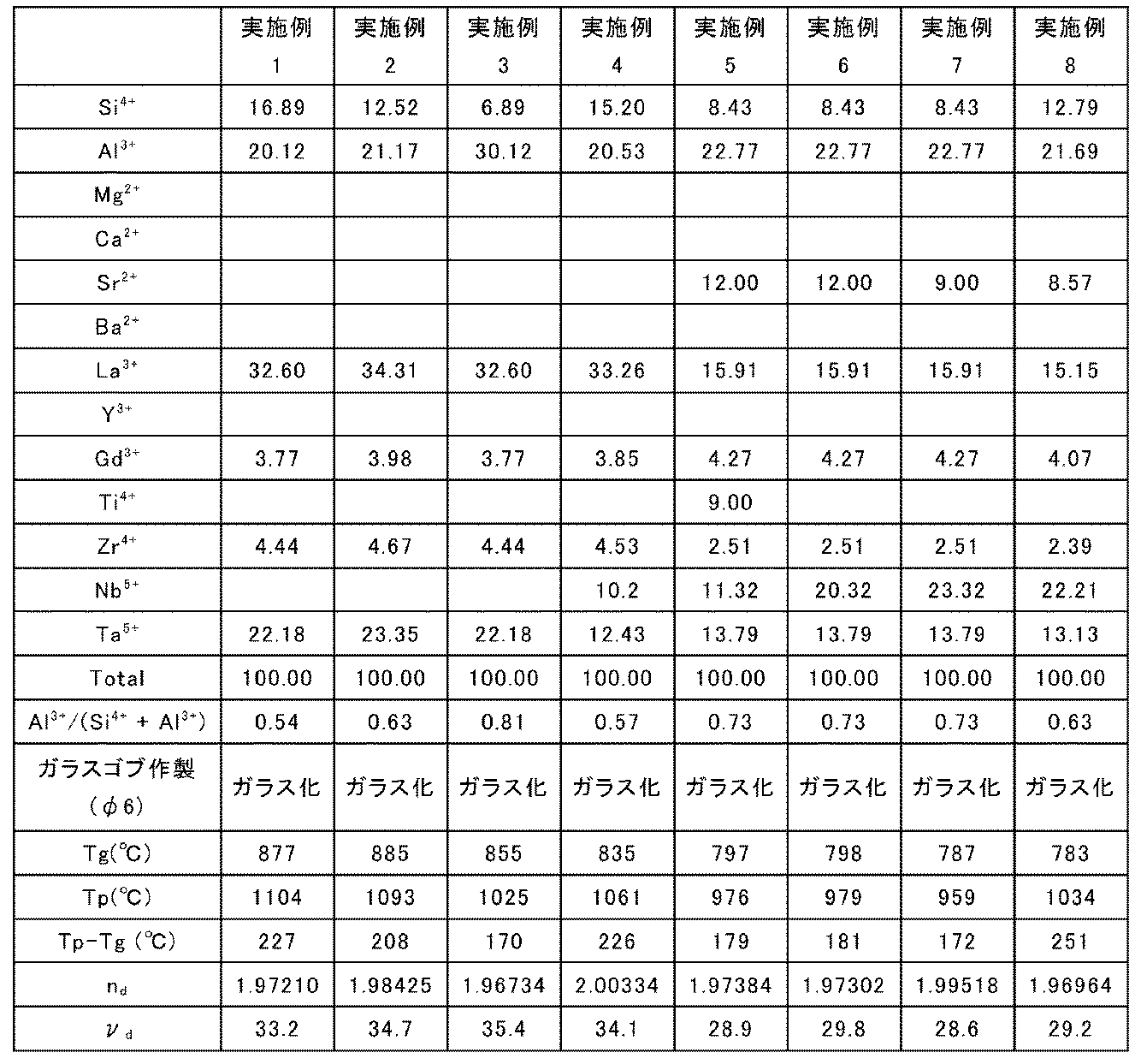
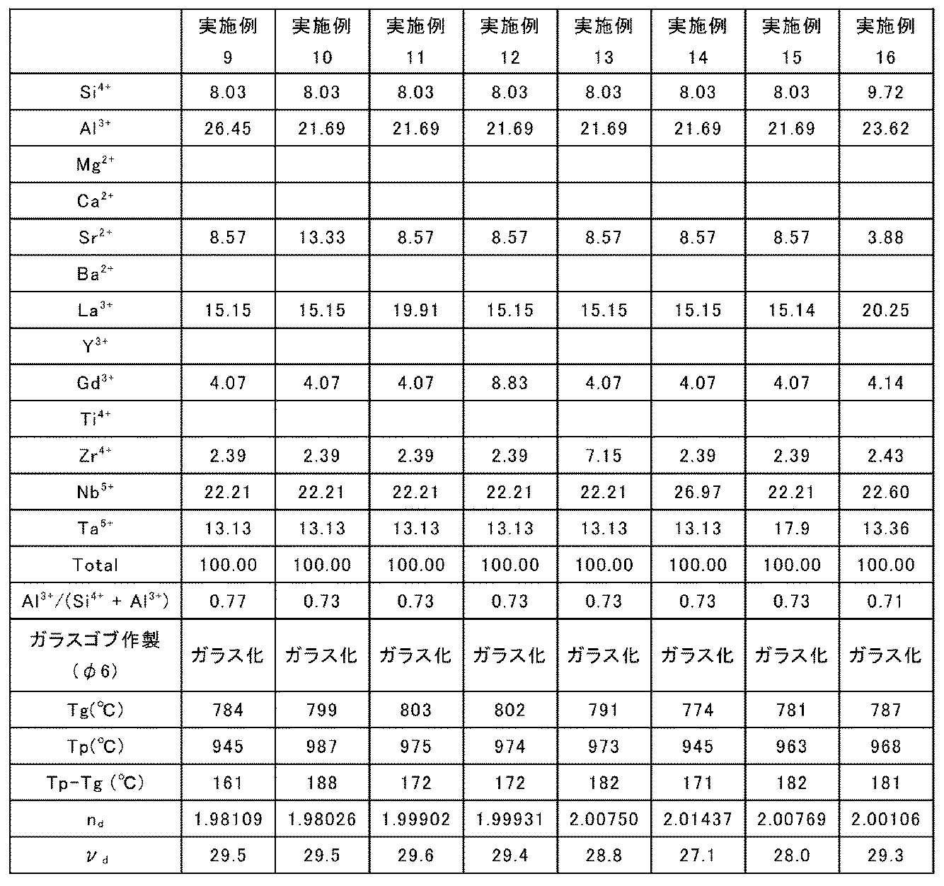
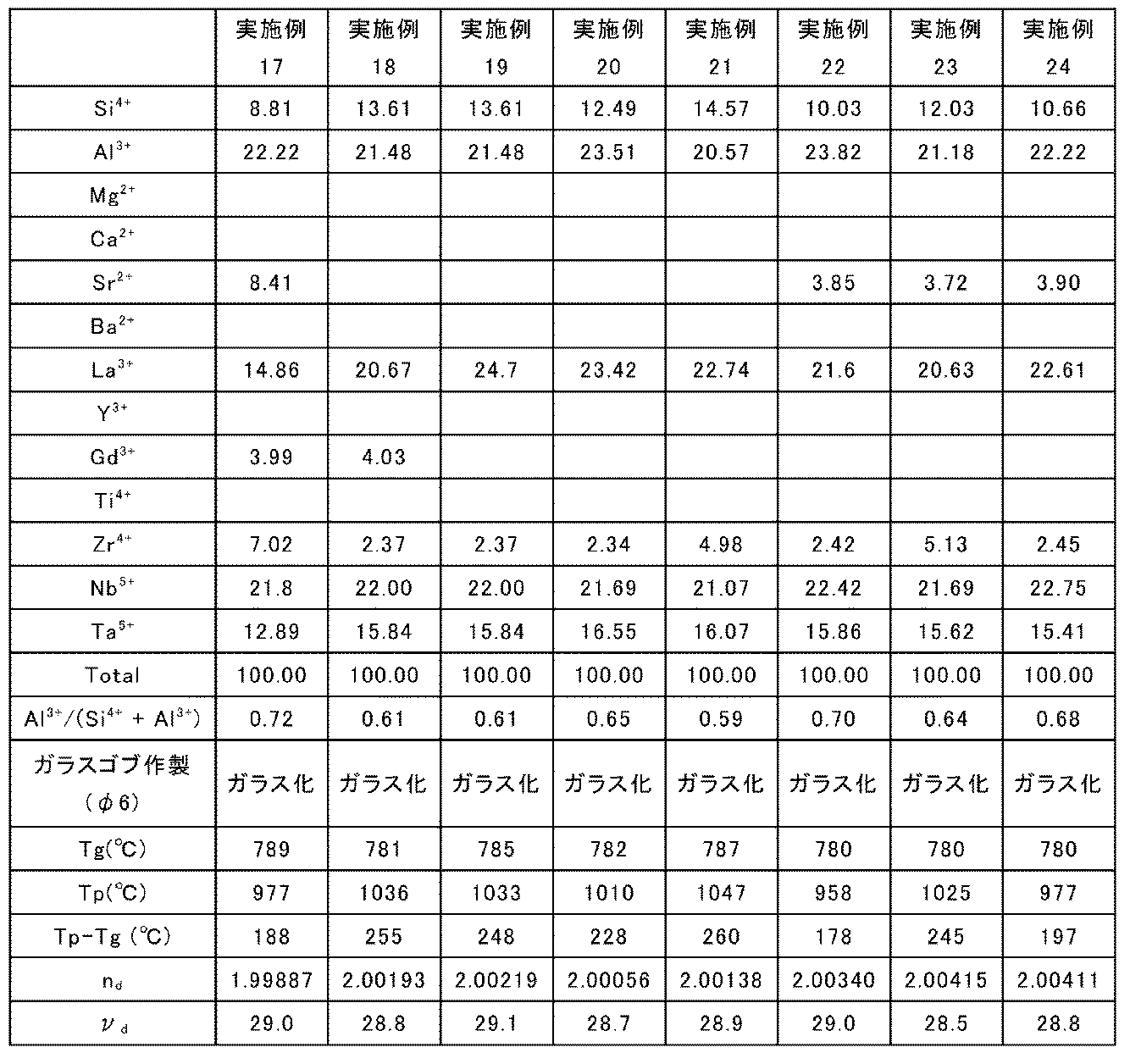
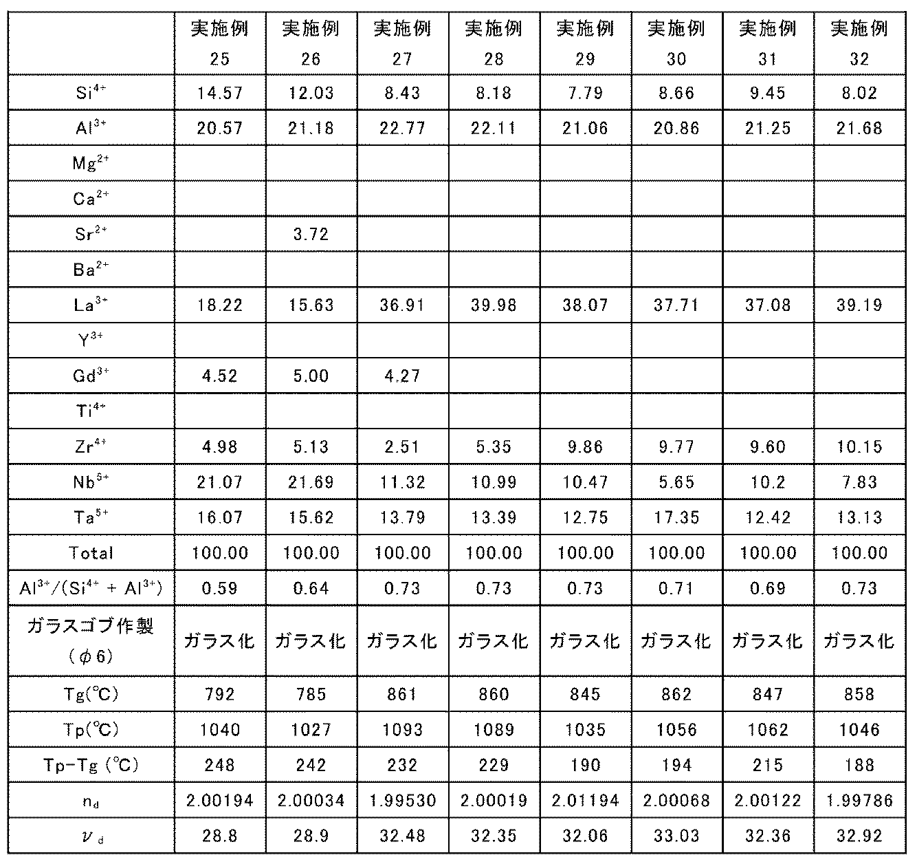
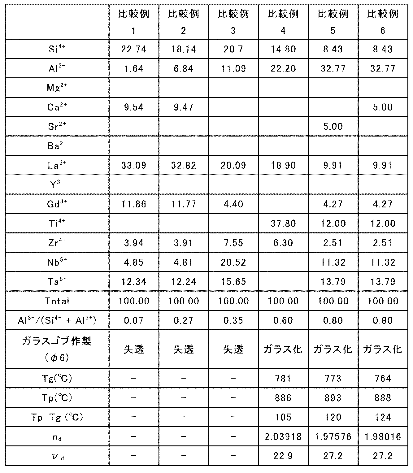
以上より、各実施例の製造方法によれば、大型のガラスゴブを安定して作製でき、かつ、得られた光学ガラスは、高屈折率、低分散性及び耐失透性を高いレベルで兼ね備えることが確認された。
1…製造装置、101…ステージ、102,111,112,113…浮遊炉用部材、103…レーザ光源、104,105…ミラー、106…放射温度計、107…コンピュータ、108…CCDカメラ、109…モニタ、110…ガス流量調節器、1020,1110,1120,1130…凹部、1022,1022a,1022b,1022c,1022d,1112,1122,1132…ガス導入部、1024,1024a,1024b,1024c,1024d,1114,1124,1134…ガス噴射部、1026,1026a,1026b,1026c,1026d…貫通孔、1126…多孔質部、1128…非多孔質部、第一の面…S1、第二の面…S2、C…中央部、O…中心点、P…周辺部、C1…第一の円、C2…第二の円、C3…第三の円、L…レーザ光、M…試料
Claims (16)
- ガス浮遊炉に用いられる浮遊炉用部材であって、
凹部を有する第一の面と、
前記第一の面と反対側にある第二の面と、
を備え、
前記第二の面は、ガスが導入されるガス導入部を有し、
前記第一の面の前記凹部は、中心部に設けられたガス噴射部と、周辺部に設けられたガス噴射部と、を有し、
前記中心部に設けられた前記ガス噴射部のガスの平均流速(VC)と、前記周辺部に設けられた前記ガス噴射部のガスの平均流速(VP)とが、下記式(1)で表される関係を満たす、浮遊炉用部材。
VC<VP ・・・(1) - さらに、下記式(2)で表される関係を満たす、
請求項1に記載の浮遊炉用部材。
0.1≦VC/VP<1 ・・・(2) - 前記周辺部は、前記中心部の外側にある、
請求項1又は2に記載の浮遊炉用部材。 - 前記中心部は、前記凹部の上面視において、前記凹部の半径(R)に対し、中心点からの半径が0.2R以下の円領域である、
請求項1~3のいずれか一項に記載の浮遊炉用部材。 - 前記周辺部は、前記凹部の上面視において、円環領域であり、
前記円環領域の内周の半径が、前記凹部の半径(R)に対し、0.4R以上であり、
前記円環領域の外周の半径が、前記凹部の半径(R)に対し、0.9R以下である、
請求項1~4のいずれか一項に記載の浮遊炉用部材。 - 前記中心部は、前記凹部の上面視において、中心点からの半径が2mm以下の円領域である、
請求項1~5のいずれか一項に記載の浮遊炉用部材。 - 前記周辺部は、前記凹部の上面視において、円環領域であり、
前記円環領域の内周の半径が、2mm以上であり、
前記円環領域の外周の半径が、9mm以下である、
請求項1~6のいずれか一項に記載の浮遊炉用部材。 - 前記凹部は、上面視において、第一の円の領域と、前記第一の円の半径以上の半径を有する第二の円の領域と、前記第二の円の半径よりも大きい半径を有する第三の円の領域と、を同心円状に有し、
前記中心部は、前記第一の円の領域であり、
前記周辺部は、前記第三の円の領域から前記第二の円の領域を除いた円環領域である、
請求項1~7のいずれか一項に記載の浮遊炉用部材。 - 前記周辺部は、前記中心部と隣接していない、
請求項1~8のいずれか一項に記載の浮遊炉用部材。 - 前記ガス導入部と前記ガス噴射部とを連通する貫通孔を含む、
請求項1~9のいずれか一項に記載の浮遊炉用部材。 - 前記凹部の上面視において、前記凹部の半径(R)が、5~10mmである、
請求項1~10のいずれか一項に記載の浮遊炉用部材。 - 前記凹部の断面視において、前記凹部の最大深さ(H)が、4~7mmである、
請求項1~11のいずれか一項に記載の浮遊炉用部材。 - 部材の少なくとも一部が、多孔質を含む、
請求項1~12のいずれか一項に記載の浮遊炉用部材。 - 部材の少なくとも一部が、ステンレス鋼(SUS)、炭化ケイ素(SiC)、アルミナ(Al2O3)、ジルコニア(ZrO2)、ジュラルミン、銅(Cu)、及びカーボン(C)からなる群より選択される少なくとも1種を含む、
請求項1~13のいずれか一項に記載の浮遊炉用部材。 - 請求項1~14のいずれか一項に記載の浮遊炉用部材を含む、浮遊炉。
- ガス浮遊炉において、請求項1~14のいずれか一項に記載の浮遊炉用部材の前記ガス噴射部から試料にガスを吹き付けて前記試料を浮遊させ、浮遊した前記試料にレーザ光を照射することによって前記試料を熔融させる工程と、
熔融した前記試料を冷却させる工程と、
を含む、光学ガラスの製造方法。
Applications Claiming Priority (2)
| Application Number | Priority Date | Filing Date | Title |
|---|---|---|---|
| JP2019-106097 | 2019-06-06 | ||
| JP2019106097 | 2019-06-06 |
Publications (1)
| Publication Number | Publication Date |
|---|---|
| WO2020246390A1 true WO2020246390A1 (ja) | 2020-12-10 |
Family
ID=73653171
Family Applications (1)
| Application Number | Title | Priority Date | Filing Date |
|---|---|---|---|
| PCT/JP2020/021378 Ceased WO2020246390A1 (ja) | 2019-06-06 | 2020-05-29 | 浮遊炉用部材、浮遊炉及び光学ガラスの製造方法 |
Country Status (1)
| Country | Link |
|---|---|
| WO (1) | WO2020246390A1 (ja) |
Citations (4)
| Publication number | Priority date | Publication date | Assignee | Title |
|---|---|---|---|---|
| JP2001192214A (ja) * | 1999-10-19 | 2001-07-17 | Hoya Corp | ガラス塊の浮上方法、ガラス塊の製造方法及び成形ガラスの製造方法並びにこれらの方法に用いる装置 |
| WO2017090471A1 (ja) * | 2015-11-25 | 2017-06-01 | 日本電気硝子株式会社 | ガラス材の製造方法及びガラス材の製造装置 |
| JP2017095308A (ja) * | 2015-11-25 | 2017-06-01 | 日本電気硝子株式会社 | ガラス材の製造方法及びガラス材の製造装置 |
| JP2017178664A (ja) * | 2016-03-30 | 2017-10-05 | 日本電気硝子株式会社 | ガラス材の製造方法及び製造装置 |
-
2020
- 2020-05-29 WO PCT/JP2020/021378 patent/WO2020246390A1/ja not_active Ceased
Patent Citations (4)
| Publication number | Priority date | Publication date | Assignee | Title |
|---|---|---|---|---|
| JP2001192214A (ja) * | 1999-10-19 | 2001-07-17 | Hoya Corp | ガラス塊の浮上方法、ガラス塊の製造方法及び成形ガラスの製造方法並びにこれらの方法に用いる装置 |
| WO2017090471A1 (ja) * | 2015-11-25 | 2017-06-01 | 日本電気硝子株式会社 | ガラス材の製造方法及びガラス材の製造装置 |
| JP2017095308A (ja) * | 2015-11-25 | 2017-06-01 | 日本電気硝子株式会社 | ガラス材の製造方法及びガラス材の製造装置 |
| JP2017178664A (ja) * | 2016-03-30 | 2017-10-05 | 日本電気硝子株式会社 | ガラス材の製造方法及び製造装置 |
Similar Documents
| Publication | Publication Date | Title |
|---|---|---|
| JP4570576B2 (ja) | 光学ガラス、プレス成形用プリフォームとその製造方法、および光学素子とその製造方法 | |
| JP5072942B2 (ja) | 光学ガラス、プレス成形用プリフォームとその製造方法、および光学素子とその製造方法 | |
| CA2663641C (en) | Titanium-containing oxide glass and method for production thereof | |
| WO2010137276A1 (ja) | ガラス | |
| WO2010071202A1 (ja) | ガラス及びガラスの処理方法 | |
| JP5063537B2 (ja) | フツリン酸ガラス、精密プレス成形用プリフォーム、光学素子ブランクおよび光学素子とそれら製造方法 | |
| JP2008001551A (ja) | 光学ガラス、ガラス成形体、光学素子およびそれらの製造方法 | |
| JP5443417B2 (ja) | フツリン酸ガラス、精密プレス成形用プリフォーム、光学素子ブランクおよび光学素子とそれら製造方法 | |
| JP2009256169A (ja) | フツリン酸ガラス、精密プレス成形用プリフォーム、光学素子ブランクおよび光学素子とそれら製造方法 | |
| JP5443416B2 (ja) | フツリン酸ガラス、精密プレス成形用プリフォーム、光学素子ブランクおよび光学素子とそれら製造方法 | |
| JP2005247598A (ja) | 精密プレス成形用プリフォームの製造方法および光学素子の製造方法 | |
| JP2018020935A (ja) | 光学ガラス及びその製造方法 | |
| JP2026048866A (ja) | 保持部材、これを用いたガラス製造装置、及びガラスの製造方法 | |
| CN112189000B (zh) | 光学玻璃、光学元件、光学设备、光学玻璃的制备方法和光学透镜的制备方法 | |
| JP2005247659A (ja) | 精密プレス成形用プリフォームの製造方法および光学素子の製造方法 | |
| JP6516084B2 (ja) | ガラス材の製造方法及びガラス材 | |
| JP4229334B2 (ja) | 光学ガラスの製造方法、プレス成形用ガラス素材、プレス成形用ガラス素材の製造方法および光学素子の製造方法 | |
| WO2010071144A1 (ja) | ガラス | |
| JP2005060193A (ja) | 光学ガラスの製造方法 | |
| RU2596836C1 (ru) | Устройство барботирования для обезвоживания стекломассы | |
| JP2019077589A (ja) | 光学ガラス、光学素子、光学機器および光学ガラスの製造方法 | |
| JP4445345B2 (ja) | ガラス成形体、プレス成形用ガラス素材、光学素子、ガラス基板それぞれの製造方法 | |
| JP3965627B2 (ja) | ガラス成形体の製造方法および光学素子の製造方法 | |
| JP6617801B2 (ja) | ガラス材の製造方法及びガラス材 | |
| JP2019214509A (ja) | ガラス材の製造方法及びガラス材 |
Legal Events
| Date | Code | Title | Description |
|---|---|---|---|
| 121 | Ep: the epo has been informed by wipo that ep was designated in this application |
Ref document number: 20819101 Country of ref document: EP Kind code of ref document: A1 |
|
| NENP | Non-entry into the national phase |
Ref country code: DE |
|
| 122 | Ep: pct application non-entry in european phase |
Ref document number: 20819101 Country of ref document: EP Kind code of ref document: A1 |
|
| NENP | Non-entry into the national phase |
Ref country code: JP |