WO2020241527A1 - 表示装置 - Google Patents
表示装置 Download PDFInfo
- Publication number
- WO2020241527A1 WO2020241527A1 PCT/JP2020/020414 JP2020020414W WO2020241527A1 WO 2020241527 A1 WO2020241527 A1 WO 2020241527A1 JP 2020020414 W JP2020020414 W JP 2020020414W WO 2020241527 A1 WO2020241527 A1 WO 2020241527A1
- Authority
- WO
- WIPO (PCT)
- Prior art keywords
- substrate
- seal
- region
- insulating layer
- layer
- Prior art date
- Legal status (The legal status is an assumption and is not a legal conclusion. Google has not performed a legal analysis and makes no representation as to the accuracy of the status listed.)
- Ceased
Links
Images





Classifications
-
- G—PHYSICS
- G02—OPTICS
- G02F—OPTICAL DEVICES OR ARRANGEMENTS FOR THE CONTROL OF LIGHT BY MODIFICATION OF THE OPTICAL PROPERTIES OF THE MEDIA OF THE ELEMENTS INVOLVED THEREIN; NON-LINEAR OPTICS; FREQUENCY-CHANGING OF LIGHT; OPTICAL LOGIC ELEMENTS; OPTICAL ANALOGUE/DIGITAL CONVERTERS
- G02F1/00—Devices or arrangements for the control of the intensity, colour, phase, polarisation or direction of light arriving from an independent light source, e.g. switching, gating or modulating; Non-linear optics
- G02F1/01—Devices or arrangements for the control of the intensity, colour, phase, polarisation or direction of light arriving from an independent light source, e.g. switching, gating or modulating; Non-linear optics for the control of the intensity, phase, polarisation or colour
- G02F1/13—Devices or arrangements for the control of the intensity, colour, phase, polarisation or direction of light arriving from an independent light source, e.g. switching, gating or modulating; Non-linear optics for the control of the intensity, phase, polarisation or colour based on liquid crystals, e.g. single liquid crystal display cells
- G02F1/133—Constructional arrangements; Operation of liquid crystal cells; Circuit arrangements
- G02F1/1333—Constructional arrangements; Manufacturing methods
- G02F1/1339—Gaskets; Spacers; Sealing of cells
-
- G—PHYSICS
- G02—OPTICS
- G02F—OPTICAL DEVICES OR ARRANGEMENTS FOR THE CONTROL OF LIGHT BY MODIFICATION OF THE OPTICAL PROPERTIES OF THE MEDIA OF THE ELEMENTS INVOLVED THEREIN; NON-LINEAR OPTICS; FREQUENCY-CHANGING OF LIGHT; OPTICAL LOGIC ELEMENTS; OPTICAL ANALOGUE/DIGITAL CONVERTERS
- G02F1/00—Devices or arrangements for the control of the intensity, colour, phase, polarisation or direction of light arriving from an independent light source, e.g. switching, gating or modulating; Non-linear optics
- G02F1/01—Devices or arrangements for the control of the intensity, colour, phase, polarisation or direction of light arriving from an independent light source, e.g. switching, gating or modulating; Non-linear optics for the control of the intensity, phase, polarisation or colour
- G02F1/13—Devices or arrangements for the control of the intensity, colour, phase, polarisation or direction of light arriving from an independent light source, e.g. switching, gating or modulating; Non-linear optics for the control of the intensity, phase, polarisation or colour based on liquid crystals, e.g. single liquid crystal display cells
- G02F1/133—Constructional arrangements; Operation of liquid crystal cells; Circuit arrangements
- G02F1/1333—Constructional arrangements; Manufacturing methods
- G02F1/133345—Insulating layers
-
- G—PHYSICS
- G02—OPTICS
- G02F—OPTICAL DEVICES OR ARRANGEMENTS FOR THE CONTROL OF LIGHT BY MODIFICATION OF THE OPTICAL PROPERTIES OF THE MEDIA OF THE ELEMENTS INVOLVED THEREIN; NON-LINEAR OPTICS; FREQUENCY-CHANGING OF LIGHT; OPTICAL LOGIC ELEMENTS; OPTICAL ANALOGUE/DIGITAL CONVERTERS
- G02F1/00—Devices or arrangements for the control of the intensity, colour, phase, polarisation or direction of light arriving from an independent light source, e.g. switching, gating or modulating; Non-linear optics
- G02F1/01—Devices or arrangements for the control of the intensity, colour, phase, polarisation or direction of light arriving from an independent light source, e.g. switching, gating or modulating; Non-linear optics for the control of the intensity, phase, polarisation or colour
- G02F1/13—Devices or arrangements for the control of the intensity, colour, phase, polarisation or direction of light arriving from an independent light source, e.g. switching, gating or modulating; Non-linear optics for the control of the intensity, phase, polarisation or colour based on liquid crystals, e.g. single liquid crystal display cells
- G02F1/133—Constructional arrangements; Operation of liquid crystal cells; Circuit arrangements
- G02F1/1333—Constructional arrangements; Manufacturing methods
- G02F1/1339—Gaskets; Spacers; Sealing of cells
- G02F1/13394—Gaskets; Spacers; Sealing of cells spacers regularly patterned on the cell subtrate, e.g. walls, pillars
-
- G—PHYSICS
- G09—EDUCATION; CRYPTOGRAPHY; DISPLAY; ADVERTISING; SEALS
- G09F—DISPLAYING; ADVERTISING; SIGNS; LABELS OR NAME-PLATES; SEALS
- G09F9/00—Indicating arrangements for variable information in which the information is built-up on a support by selection or combination of individual elements
- G09F9/30—Indicating arrangements for variable information in which the information is built-up on a support by selection or combination of individual elements in which the desired character or characters are formed by combining individual elements
-
- H—ELECTRICITY
- H05—ELECTRIC TECHNIQUES NOT OTHERWISE PROVIDED FOR
- H05B—ELECTRIC HEATING; ELECTRIC LIGHT SOURCES NOT OTHERWISE PROVIDED FOR; CIRCUIT ARRANGEMENTS FOR ELECTRIC LIGHT SOURCES, IN GENERAL
- H05B33/00—Electroluminescent light sources
- H05B33/02—Details
-
- H—ELECTRICITY
- H05—ELECTRIC TECHNIQUES NOT OTHERWISE PROVIDED FOR
- H05B—ELECTRIC HEATING; ELECTRIC LIGHT SOURCES NOT OTHERWISE PROVIDED FOR; CIRCUIT ARRANGEMENTS FOR ELECTRIC LIGHT SOURCES, IN GENERAL
- H05B33/00—Electroluminescent light sources
- H05B33/02—Details
- H05B33/04—Sealing arrangements, e.g. against humidity
-
- H—ELECTRICITY
- H05—ELECTRIC TECHNIQUES NOT OTHERWISE PROVIDED FOR
- H05B—ELECTRIC HEATING; ELECTRIC LIGHT SOURCES NOT OTHERWISE PROVIDED FOR; CIRCUIT ARRANGEMENTS FOR ELECTRIC LIGHT SOURCES, IN GENERAL
- H05B33/00—Electroluminescent light sources
- H05B33/02—Details
- H05B33/06—Electrode terminals
-
- H—ELECTRICITY
- H05—ELECTRIC TECHNIQUES NOT OTHERWISE PROVIDED FOR
- H05B—ELECTRIC HEATING; ELECTRIC LIGHT SOURCES NOT OTHERWISE PROVIDED FOR; CIRCUIT ARRANGEMENTS FOR ELECTRIC LIGHT SOURCES, IN GENERAL
- H05B33/00—Electroluminescent light sources
- H05B33/12—Light sources with substantially two-dimensional [2D] radiating surfaces
-
- H—ELECTRICITY
- H05—ELECTRIC TECHNIQUES NOT OTHERWISE PROVIDED FOR
- H05B—ELECTRIC HEATING; ELECTRIC LIGHT SOURCES NOT OTHERWISE PROVIDED FOR; CIRCUIT ARRANGEMENTS FOR ELECTRIC LIGHT SOURCES, IN GENERAL
- H05B33/00—Electroluminescent light sources
- H05B33/12—Light sources with substantially two-dimensional [2D] radiating surfaces
- H05B33/22—Light sources with substantially two-dimensional [2D] radiating surfaces characterised by the chemical or physical composition or the arrangement of auxiliary dielectric or reflective layers
-
- H—ELECTRICITY
- H05—ELECTRIC TECHNIQUES NOT OTHERWISE PROVIDED FOR
- H05B—ELECTRIC HEATING; ELECTRIC LIGHT SOURCES NOT OTHERWISE PROVIDED FOR; CIRCUIT ARRANGEMENTS FOR ELECTRIC LIGHT SOURCES, IN GENERAL
- H05B33/00—Electroluminescent light sources
- H05B33/12—Light sources with substantially two-dimensional [2D] radiating surfaces
- H05B33/26—Light sources with substantially two-dimensional [2D] radiating surfaces characterised by the composition or arrangement of the conductive material used as an electrode
- H05B33/28—Light sources with substantially two-dimensional [2D] radiating surfaces characterised by the composition or arrangement of the conductive material used as an electrode of translucent electrodes
-
- G—PHYSICS
- G02—OPTICS
- G02F—OPTICAL DEVICES OR ARRANGEMENTS FOR THE CONTROL OF LIGHT BY MODIFICATION OF THE OPTICAL PROPERTIES OF THE MEDIA OF THE ELEMENTS INVOLVED THEREIN; NON-LINEAR OPTICS; FREQUENCY-CHANGING OF LIGHT; OPTICAL LOGIC ELEMENTS; OPTICAL ANALOGUE/DIGITAL CONVERTERS
- G02F1/00—Devices or arrangements for the control of the intensity, colour, phase, polarisation or direction of light arriving from an independent light source, e.g. switching, gating or modulating; Non-linear optics
- G02F1/01—Devices or arrangements for the control of the intensity, colour, phase, polarisation or direction of light arriving from an independent light source, e.g. switching, gating or modulating; Non-linear optics for the control of the intensity, phase, polarisation or colour
- G02F1/13—Devices or arrangements for the control of the intensity, colour, phase, polarisation or direction of light arriving from an independent light source, e.g. switching, gating or modulating; Non-linear optics for the control of the intensity, phase, polarisation or colour based on liquid crystals, e.g. single liquid crystal display cells
- G02F1/133—Constructional arrangements; Operation of liquid crystal cells; Circuit arrangements
- G02F1/1333—Constructional arrangements; Manufacturing methods
- G02F1/133357—Planarisation layers
-
- G—PHYSICS
- G02—OPTICS
- G02F—OPTICAL DEVICES OR ARRANGEMENTS FOR THE CONTROL OF LIGHT BY MODIFICATION OF THE OPTICAL PROPERTIES OF THE MEDIA OF THE ELEMENTS INVOLVED THEREIN; NON-LINEAR OPTICS; FREQUENCY-CHANGING OF LIGHT; OPTICAL LOGIC ELEMENTS; OPTICAL ANALOGUE/DIGITAL CONVERTERS
- G02F1/00—Devices or arrangements for the control of the intensity, colour, phase, polarisation or direction of light arriving from an independent light source, e.g. switching, gating or modulating; Non-linear optics
- G02F1/01—Devices or arrangements for the control of the intensity, colour, phase, polarisation or direction of light arriving from an independent light source, e.g. switching, gating or modulating; Non-linear optics for the control of the intensity, phase, polarisation or colour
- G02F1/13—Devices or arrangements for the control of the intensity, colour, phase, polarisation or direction of light arriving from an independent light source, e.g. switching, gating or modulating; Non-linear optics for the control of the intensity, phase, polarisation or colour based on liquid crystals, e.g. single liquid crystal display cells
- G02F1/133—Constructional arrangements; Operation of liquid crystal cells; Circuit arrangements
- G02F1/1333—Constructional arrangements; Manufacturing methods
- G02F1/133388—Constructional arrangements; Manufacturing methods with constructional differences between the display region and the peripheral region
-
- G—PHYSICS
- G02—OPTICS
- G02F—OPTICAL DEVICES OR ARRANGEMENTS FOR THE CONTROL OF LIGHT BY MODIFICATION OF THE OPTICAL PROPERTIES OF THE MEDIA OF THE ELEMENTS INVOLVED THEREIN; NON-LINEAR OPTICS; FREQUENCY-CHANGING OF LIGHT; OPTICAL LOGIC ELEMENTS; OPTICAL ANALOGUE/DIGITAL CONVERTERS
- G02F1/00—Devices or arrangements for the control of the intensity, colour, phase, polarisation or direction of light arriving from an independent light source, e.g. switching, gating or modulating; Non-linear optics
- G02F1/01—Devices or arrangements for the control of the intensity, colour, phase, polarisation or direction of light arriving from an independent light source, e.g. switching, gating or modulating; Non-linear optics for the control of the intensity, phase, polarisation or colour
- G02F1/13—Devices or arrangements for the control of the intensity, colour, phase, polarisation or direction of light arriving from an independent light source, e.g. switching, gating or modulating; Non-linear optics for the control of the intensity, phase, polarisation or colour based on liquid crystals, e.g. single liquid crystal display cells
- G02F1/133—Constructional arrangements; Operation of liquid crystal cells; Circuit arrangements
- G02F1/1333—Constructional arrangements; Manufacturing methods
- G02F1/1335—Structural association of cells with optical devices, e.g. polarisers or reflectors
- G02F1/133509—Filters, e.g. light shielding masks
- G02F1/133512—Light shielding layers, e.g. black matrix
-
- G—PHYSICS
- G02—OPTICS
- G02F—OPTICAL DEVICES OR ARRANGEMENTS FOR THE CONTROL OF LIGHT BY MODIFICATION OF THE OPTICAL PROPERTIES OF THE MEDIA OF THE ELEMENTS INVOLVED THEREIN; NON-LINEAR OPTICS; FREQUENCY-CHANGING OF LIGHT; OPTICAL LOGIC ELEMENTS; OPTICAL ANALOGUE/DIGITAL CONVERTERS
- G02F1/00—Devices or arrangements for the control of the intensity, colour, phase, polarisation or direction of light arriving from an independent light source, e.g. switching, gating or modulating; Non-linear optics
- G02F1/01—Devices or arrangements for the control of the intensity, colour, phase, polarisation or direction of light arriving from an independent light source, e.g. switching, gating or modulating; Non-linear optics for the control of the intensity, phase, polarisation or colour
- G02F1/13—Devices or arrangements for the control of the intensity, colour, phase, polarisation or direction of light arriving from an independent light source, e.g. switching, gating or modulating; Non-linear optics for the control of the intensity, phase, polarisation or colour based on liquid crystals, e.g. single liquid crystal display cells
- G02F1/133—Constructional arrangements; Operation of liquid crystal cells; Circuit arrangements
- G02F1/1333—Constructional arrangements; Manufacturing methods
- G02F1/1335—Structural association of cells with optical devices, e.g. polarisers or reflectors
- G02F1/133509—Filters, e.g. light shielding masks
- G02F1/133514—Colour filters
-
- G—PHYSICS
- G02—OPTICS
- G02F—OPTICAL DEVICES OR ARRANGEMENTS FOR THE CONTROL OF LIGHT BY MODIFICATION OF THE OPTICAL PROPERTIES OF THE MEDIA OF THE ELEMENTS INVOLVED THEREIN; NON-LINEAR OPTICS; FREQUENCY-CHANGING OF LIGHT; OPTICAL LOGIC ELEMENTS; OPTICAL ANALOGUE/DIGITAL CONVERTERS
- G02F1/00—Devices or arrangements for the control of the intensity, colour, phase, polarisation or direction of light arriving from an independent light source, e.g. switching, gating or modulating; Non-linear optics
- G02F1/01—Devices or arrangements for the control of the intensity, colour, phase, polarisation or direction of light arriving from an independent light source, e.g. switching, gating or modulating; Non-linear optics for the control of the intensity, phase, polarisation or colour
- G02F1/13—Devices or arrangements for the control of the intensity, colour, phase, polarisation or direction of light arriving from an independent light source, e.g. switching, gating or modulating; Non-linear optics for the control of the intensity, phase, polarisation or colour based on liquid crystals, e.g. single liquid crystal display cells
- G02F1/133—Constructional arrangements; Operation of liquid crystal cells; Circuit arrangements
- G02F1/1333—Constructional arrangements; Manufacturing methods
- G02F1/1337—Surface-induced orientation of the liquid crystal molecules, e.g. by alignment layers
-
- G—PHYSICS
- G02—OPTICS
- G02F—OPTICAL DEVICES OR ARRANGEMENTS FOR THE CONTROL OF LIGHT BY MODIFICATION OF THE OPTICAL PROPERTIES OF THE MEDIA OF THE ELEMENTS INVOLVED THEREIN; NON-LINEAR OPTICS; FREQUENCY-CHANGING OF LIGHT; OPTICAL LOGIC ELEMENTS; OPTICAL ANALOGUE/DIGITAL CONVERTERS
- G02F1/00—Devices or arrangements for the control of the intensity, colour, phase, polarisation or direction of light arriving from an independent light source, e.g. switching, gating or modulating; Non-linear optics
- G02F1/01—Devices or arrangements for the control of the intensity, colour, phase, polarisation or direction of light arriving from an independent light source, e.g. switching, gating or modulating; Non-linear optics for the control of the intensity, phase, polarisation or colour
- G02F1/13—Devices or arrangements for the control of the intensity, colour, phase, polarisation or direction of light arriving from an independent light source, e.g. switching, gating or modulating; Non-linear optics for the control of the intensity, phase, polarisation or colour based on liquid crystals, e.g. single liquid crystal display cells
- G02F1/133—Constructional arrangements; Operation of liquid crystal cells; Circuit arrangements
- G02F1/1333—Constructional arrangements; Manufacturing methods
- G02F1/1339—Gaskets; Spacers; Sealing of cells
- G02F1/13392—Gaskets; Spacers; Sealing of cells spacers dispersed on the cell substrate, e.g. spherical particles, microfibres
-
- G—PHYSICS
- G02—OPTICS
- G02F—OPTICAL DEVICES OR ARRANGEMENTS FOR THE CONTROL OF LIGHT BY MODIFICATION OF THE OPTICAL PROPERTIES OF THE MEDIA OF THE ELEMENTS INVOLVED THEREIN; NON-LINEAR OPTICS; FREQUENCY-CHANGING OF LIGHT; OPTICAL LOGIC ELEMENTS; OPTICAL ANALOGUE/DIGITAL CONVERTERS
- G02F1/00—Devices or arrangements for the control of the intensity, colour, phase, polarisation or direction of light arriving from an independent light source, e.g. switching, gating or modulating; Non-linear optics
- G02F1/01—Devices or arrangements for the control of the intensity, colour, phase, polarisation or direction of light arriving from an independent light source, e.g. switching, gating or modulating; Non-linear optics for the control of the intensity, phase, polarisation or colour
- G02F1/13—Devices or arrangements for the control of the intensity, colour, phase, polarisation or direction of light arriving from an independent light source, e.g. switching, gating or modulating; Non-linear optics for the control of the intensity, phase, polarisation or colour based on liquid crystals, e.g. single liquid crystal display cells
- G02F1/133—Constructional arrangements; Operation of liquid crystal cells; Circuit arrangements
- G02F1/1333—Constructional arrangements; Manufacturing methods
- G02F1/1339—Gaskets; Spacers; Sealing of cells
- G02F1/13396—Spacers having different sizes
-
- H—ELECTRICITY
- H10—SEMICONDUCTOR DEVICES; ELECTRIC SOLID-STATE DEVICES NOT OTHERWISE PROVIDED FOR
- H10K—ORGANIC ELECTRIC SOLID-STATE DEVICES
- H10K59/00—Integrated devices, or assemblies of multiple devices, comprising at least one organic light-emitting element covered by group H10K50/00
Definitions
- An embodiment of the present invention relates to a display device.
- TFT substrate in which pixels having pixel electrodes, thin film transistors (TFTs) and the like are formed in a matrix, and an opposing substrate facing the TFT substrate are provided, and liquid crystal molecules are rotated by an electric field in a direction parallel to the two substrates.
- Various display devices have been studied. As an example, a display device is disclosed in which an organic insulating layer has groove-shaped through holes formed so as to surround a region sandwiching a liquid crystal in a region where two substrates overlap.
- An object of the present embodiment is to provide a display device capable of narrowing the frame and further improving the yield of products.
- the display device is A first substrate having a first region including a display area and a frame area, and a second region adjacent to the first region, and a first end located at a boundary between the first region and the second region.
- a second substrate having a portion and a second end portion different from the first end portion and overlapping the first region, and the first substrate and the second substrate located in the frame region are attached.
- the width of the frame area between the first end and the display area is smaller than the width of the frame area between the second end and the display area, and the first The width of the seal between one end and the display area is smaller than the width of the seal between the second end and the display area.
- FIG. 1 is a plan view showing a liquid crystal display device of one embodiment.
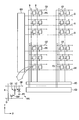
- FIG. 2 is a diagram showing a basic configuration of pixels and an equivalent circuit shown in FIG.
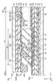
- FIG. 3 is a cross-sectional view showing a configuration example of the display panel shown in FIG.
- FIG. 4 is a plan view of the second substrate SUB2 shown in FIG. 1 and is a diagram for explaining a display area DA.
- FIG. 5 is a plan view showing the liquid crystal display device shown in FIG. 1 and is a diagram for explaining the positional relationship between the groove portion and the wiring group.
- FIG. 6 is a plan view showing the liquid crystal display device shown in FIG. 5, and is a diagram for explaining the positional relationship between the groove and the recess.
- FIG. 5 is a plan view showing the liquid crystal display device shown in FIG. 5, and is a diagram for explaining the positional relationship between the groove and the recess.
- FIG. 5 is a plan view showing the liquid crystal display device shown in FIG. 5, and is a diagram
- FIG. 7 is a cross-sectional view of the display panel taken along the line AB shown in FIG.
- FIG. 8 is a cross-sectional view of the display panel taken along the line CD shown in FIG.
- FIG. 9 is a plan view for explaining a spacer of a modified example of the present embodiment.
- FIG. 1 is a plan view showing a liquid crystal display device DSP of one embodiment.
- the first direction X, the second direction Y, and the third direction Z are orthogonal to each other, but may intersect at an angle other than 90 degrees.
- the first direction X and the second direction Y correspond to the directions parallel to the main surface of the substrate constituting the liquid crystal display device DSP
- the third direction Z corresponds to the thickness direction of the liquid crystal display device DSP.
- the position on the tip end side of the arrow indicating the third direction Z is referred to as an upper position
- the position opposite to the tip end of the arrow is referred to as a lower position.
- the liquid crystal display device DSP includes a display panel PNL, an IC chip 1, and a wiring board F1.
- the display panel PNL includes a first substrate SUB1, a second substrate SUB2, a liquid crystal layer LC, and a seal SE.
- the liquid crystal layer LC and the seal SE are shown by different diagonal lines.
- the display panel PNL includes a first region A1 and a second region A2 arranged in the second direction Y.
- the first substrate SUB1 has ends E11 and E12 extending along the first direction X and ends E13 and E14 extending along the second direction Y.
- the second substrate SUB2 has ends E21 and E22 extending along the first direction X and ends E23 and E24 extending along the second direction Y.
- the end portion E21 corresponds to the edge of the substrate located at the boundary between the first region A1 and the second region A2. That is, the first region A1 corresponds to the region surrounded by the ends E21, E12, E13 and E14.
- the second region A2 corresponds to the region surrounded by the ends E11, E21, E13 and E14.
- first region A1 is a portion of two display panels PNL on which the first substrate SUB1 and the second substrate SUB2 overlap each other
- second region A2 is one of the display panels PNL on which the first substrate SUB1 is exposed from the second substrate SUB2. It can also be called a part.
- the first area A1 includes a display area DA for displaying an image and a frame-shaped frame area FA surrounding the display area DA.
- the display area DA is shown as a substantially quadrangular area, the four corners may be rounded, or may be a polygon or a circle other than the quadrangle. Further, a notch for a camera may be formed at the end portion E12 and the end portion E22.
- the display area DA is located inside surrounded by the seal SE.
- the display area DA has sides ED1 and ED2 extending along the first direction X, and sides ED3 and ED4 extending along the second direction Y.
- the side ED1 is close to the end E21
- the side ED2 is close to the end E22
- the side ED3 is close to the end E23
- the side ED4 is close to the end E24.
- a plurality of pixel PXs arranged in a matrix (matrix) in the first direction (column direction) X and the second direction (row direction) Y are located.
- the pixel PX here indicates a minimum unit that can be individually controlled according to a pixel signal, and may be referred to as a sub-pixel.
- the pixel PX is, for example, either a red pixel that displays red, a green pixel that displays green, a blue pixel that displays blue, or a white pixel that displays white.
- the seal SE is located in the frame region FA, joins the first substrate SUB1 and the second substrate SUB2, and seals the liquid crystal layer LC.
- the seal SE includes a first seal portion P1 and a second seal portion P2 extending along the first direction X, and a third seal portion P3 and a fourth seal portion P4 extending along the second direction Y.
- the first seal portion P1 is located between the side ED1 and the end portion E21 and has a substantially constant width W1.
- the first seal portion P1 is separated from the end portion E21.
- the second seal portion P2 overlaps the end portion E22 and has a substantially constant width W2.
- the third seal portion P3 overlaps the end portion E23 and has a substantially constant width W3.
- the fourth seal portion P4 overlaps the end portion E24 and has a substantially constant width W4.
- the widths W1 to W4 correspond to the lengths along the direction orthogonal to the extending direction of the seal SE.
- the width W1 is smaller than each of the widths W2 to W4.
- the width W1 is about 350 ⁇ m, and the widths W2 to W4 are each about 400 ⁇ m.
- the width W1 may be the same as each of the widths W2 to W4.
- display devices including liquid crystal display devices are required to have a narrower frame in which the width of the frame area FA is narrowed, and the width of the seal SE is also narrowed as the frame area FA is narrowed.
- the panel upper frame is a frame area having a width WF2 including an upper side of the panel including the end E12 of the first substrate SUB1 and the end E22 of the second substrate SUB2 and the side ED2 of the display area DA.
- the panel left frame is a frame area having a width WF3 including the left side of the panel including the end E13 of the first substrate SUB1 and the end E23 of the second substrate SUB2 and the side ED3 of the display area DA.
- the panel right frame is a frame area having a width WF4 including the right side of the panel including the end E14 of the first substrate SUB1 and the end E24 of the second substrate SUB2 and the side ED4 of the display area DA.
- the lower panel frame is the second region A2 of the first substrate SUB1, the end E11 of the first substrate SUB1 which is the lower side of the panel itself, and the end E21 of the second substrate SUB2 and the display region DA. It is a frame area including the side ED1.
- the end portion E21 of the second substrate SUB2 and the side ED1 of the display area DA can be said to be the terminal side frame of the second substrate SUB2, and the terminal side frame of the second substrate SUB2 has a width WF1.
- the width WF1 is smaller than each of the width WF2 and the width WF4.
- the widths WF2 to WF4 are 0.7 to 1.0 mm, and the width WF1 is 0.4 to 0.69 mm.
- the width WF1 is as small as possible in order to narrow the vertical and horizontal frame town areas of the panel.
- the IC chip 1 and the wiring board F1 may read a signal from the display panel PNL, but mainly function as a signal source for supplying a signal to the display panel PNL. These signal sources are mounted in the second region A2.
- the wiring board F1 and the IC chip 1 are each mounted in the second region A2.
- the IC chip 1 may be mounted on the wiring board F1.
- the IC chip 1 has a built-in display driver DD that outputs a signal required for image display in an image display mode for displaying an image.
- the IC chip 1 has a built-in touch controller TCN that controls a touch sensing mode for detecting the approach or contact of an object with the liquid crystal display device DSP.
- the display panel PNL of the present embodiment is a transmissive display panel PNL having a transmissive display function for displaying an image by selectively transmitting light from the back side of the first substrate SUB1, and the front surface of the second substrate SUB2.
- a reflective display panel PNL with a reflective display function that displays an image by selectively reflecting light from the side or a semi-transparent display panel PNL with a transparent display function and a reflective display function. There may be.
- the display panel PNL has a display mode using a lateral electric field along the main surface of the substrate and a vertical electric field along the normal of the main surface of the substrate. It corresponds to the display mode to be used, the display mode to use the gradient electric field inclined in the diagonal direction with respect to the main surface of the substrate, and the display mode to use the above-mentioned lateral electric field, longitudinal electric field, and gradient electric field in an appropriate combination. Any configuration may be provided.
- the main surface of the substrate here is a surface parallel to the XY plane defined by the first direction X and the second direction Y.
- the display panel PNL is not limited to the liquid crystal display device DSP, but if there is a first substrate SUB1, a second substrate SUB2, and a seal SE, it is like an organic EL (Electro Luminescence) display device or a micro LED (Light Emitting Diode) display device. It can also be applied to self-luminous display devices.
- the seal SE may be a resin seal used in the liquid crystal display device, and glass frit may be considered.
- FIG. 2 is a diagram showing a basic configuration and an equivalent circuit of the pixel PX shown in FIG.
- the plurality of scanning lines G are connected to the scanning line driving circuit GD, and the plurality of signal lines S are connected to the signal line driving circuit SD.
- the scanning line GE is the scanning line closest to the end portion E21 shown in FIG. 1 among the scanning lines G connected to the scanning line driving circuit GD.
- the scanning line GE is located at the boundary between the display area DA and the frame area FA, and extends along the side ED1 of the display area DA.
- the scanning line G and the signal line S are metal materials such as aluminum (Al), titanium (Ti), silver (Ag), molybdenum (Mo), tungsten (W), copper (Cu), and chromium (Cr), respectively.
- the scanning line G and the signal line S may have a single-layer structure or a multi-layer structure, respectively.
- the scanning line G and the signal line S do not necessarily have to extend linearly, and a part of them may be bent.
- the common electrode CE is arranged over a plurality of pixels PX.
- the common electrode CE is connected to the voltage supply unit CD and the touch controller TCN shown in FIG.
- the voltage supply unit CD supplies a common voltage (Vcom) to the common electrode CE.
- the touch controller TCN supplies a touch drive voltage different from the common voltage to the common electrode CE.
- Each pixel PX includes a switching element SW, a pixel electrode PE, a common electrode CE, a liquid crystal layer LC, and the like.
- the switching element SW is composed of, for example, a TFT, and is electrically connected to the scanning line G and the signal line S.
- the scanning line G is electrically connected to the switching element SW in each of the pixels PX arranged in the first direction X.
- the signal line S is electrically connected to the switching element SW in each of the pixels PX arranged in the second direction Y.
- a control signal for controlling the switching element SW is supplied to the scanning line G.
- a video signal is supplied to the signal line S as a signal different from the control signal.
- the pixel electrode PE is electrically connected to the switching element SW.
- the liquid crystal layer LC is driven by an electric field generated between the pixel electrode PE and the common electrode CE.
- the capacitance CS is formed, for example, between an electrode having the same potential as the common electrode CE and an electrode having the same potential as the
- FIG. 3 is a cross-sectional view showing a configuration example of the display panel PNL shown in FIG.
- the illustrated example corresponds to an example in which the FFS (Fringe Field Switching) mode, which is one of the display modes using the lateral electric field, is applied.
- the first substrate SUB1 includes an insulating substrate 10, insulating layers 11 to 16, semiconductor layer SC, signal line S, metal wiring ML, common electrode CE, pixel electrode PE, alignment film AL1, and the like.
- the insulating substrate 10 is a transparent substrate such as a glass substrate or a flexible resin substrate.
- the insulating layer 11 is located on the insulating substrate 10.
- the semiconductor layer SC is located on the insulating layer 11 and is covered with the insulating layer 12.
- the semiconductor layer SC is formed of, for example, polycrystalline silicon, but may be formed of amorphous silicon or an oxide semiconductor.
- the insulating layer 12 is covered with the insulating layer 13.
- the scanning line G shown in FIG. 2 is located between the insulating layers 12 and 13.
- the insulating layer 14 has a lower surface 14A and an upper surface 14B on the opposite side of the lower surface 14A.
- the insulating layer 15 has a lower surface 15A facing the upper surface 14B and an upper surface 15B opposite the lower surface 15A.
- the signal line S is located on the insulating layer 13 and is covered with the insulating layer 14.
- the metal wiring ML is located on the upper surface 14B and is covered with the insulating layer 15.
- the metal wiring ML includes, for example, metal materials such as aluminum (Al), titanium (Ti), silver (Ag), molybdenum (Mo), tungsten (W), copper (Cu), and chromium (Cr), and these metals. It is formed of an alloy that combines materials.
- the metal wiring ML may have a single-layer structure or a multi-layer structure. Each of the metal wiring MLs extends parallel to the signal line S and is located directly above the signal line S.
- the common electrode CE is located on the upper surface 15B and is covered with the insulating layer 16.
- the pixel electrode PE is located on the insulating layer 16 and is covered with the alignment film AL1.
- Each of the pixel electrode PEs faces the common electrode CE via the insulating layer 16.
- the common electrode CE and the pixel electrode PE are formed of a transparent conductive material such as indium tin oxide (ITO) or indium zinc oxide (IZO).
- the pixel electrode PE is a linear electrode
- the common electrode CE is a flat plate-shaped electrode commonly provided over a plurality of pixel PXs.
- the pixel electrode PE may be a flat plate electrode, and a linear common electrode may be provided between the pixel electrode PE and the liquid crystal layer LC.
- the insulating layer 11, the insulating layer 12, and the insulating layers 13 and 16 are inorganic insulating layers formed of an inorganic insulating material such as silicon oxide (SiO), silicon nitride (SiN), and silicon oxynitride (SiON). ..
- the insulating layer 16 is formed of, for example, silicon nitride.
- the insulating layer 11, the insulating layer 12, and the insulating layers 13 and 16 may have a single-layer structure or a multi-layer structure.
- the insulating layers 14 and 15 are organic insulating layers formed of, for example, an organic insulating material such as an acrylic resin.
- the upper surface 14B, the lower surface 15A, and the upper surface 15B are each flattened.
- the insulating layer 15 has a thickness H1.
- the thickness H1 corresponds to the distance from the lower surface 15A to the upper surface 15B in the third direction Z.
- the thickness H1 is, for example, 1.5 ⁇ m
- the second substrate SUB2 includes an insulating substrate 20, a color filter CF, a light-shielding layer BM, a transparent layer OC, and an alignment film AL2.
- the insulating substrate 20 is a transparent substrate such as a glass substrate or a flexible resin substrate.
- the color filter CF, the light-shielding layer BM, and the transparent layer OC are located between the insulating substrate 20 and the liquid crystal layer LC.
- the alignment film AL2 is in contact with the liquid crystal layer LC.
- the alignment films AL1 and AL2 are formed of, for example, a material exhibiting horizontal orientation.
- the transparent layer OC covers the color filter CF and the light-shielding layer BM.
- the transparent layer OC is, for example, a transparent organic insulating layer.
- the color filter CF is provided on the second substrate SUB2, but it may be provided on the first substrate SUB1.
- the color filter CF includes a red color filter CFR, a green color filter CFG, and a blue color filter CFB.
- the green color filter CFG faces the pixel electrode PE.
- the red color filter CFR and the blue color filter CFB also face each other pixel electrode PE (not shown).
- the liquid crystal layer LC is located between the first substrate SUB1 and the second substrate SUB2, and is held between the alignment film AL1 and the alignment film AL2.
- the liquid crystal layer LC includes a liquid crystal molecule LM.
- the liquid crystal layer LC is composed of a positive type (positive dielectric anisotropy) liquid crystal material or a negative type (negative dielectric anisotropy) liquid crystal material.
- the liquid crystal molecules LM are initially oriented in a predetermined direction between the alignment films AL1 and AL2 in an off state in which an electric field is not formed between the pixel electrode PE and the common electrode CE. ing. In such an off state, the illumination light emitted from the illumination device IL toward the display panel PNL is absorbed by the optical elements OD1 and OD2, resulting in dark display. On the other hand, in the on state where an electric field is formed between the pixel electrode PE and the common electrode CE, the liquid crystal molecule LM is oriented in a direction different from the initial orientation direction due to the electric field, and the orientation direction is controlled by the electric field. .. In such an on state, a part of the illumination light from the illumination device IL passes through the optical elements OD1 and OD2 and becomes a bright display.
- FIG. 4 is a plan view of the second substrate SUB2 shown in FIG. 1 and is a diagram for explaining a display area DA.
- the light-shielding layer BM extends to each of the ends E21 to E24 and is provided over the entire first region A1.
- the light-shielding layer BM has a plurality of openings OP. Each opening OP corresponds to each pixel PX shown in FIGS. 2 and 3, respectively.
- the red color filter CFR, the green color filter CFG, and the blue color filter CFB which are units constituting one pixel in the first direction X, are arranged in each opening OP so as to be arranged in this order.
- the side ED1 is located on the same line as the outermost side of the plurality of opening OPs close to the end E21, and the side ED2 is located on the same line as the outermost side of the plurality of opening OPs close to the end E22.
- the display area DA can also be said to be an area including a plurality of opening OPs of the light-shielding layer BM.
- FIG. 5 is a plan view showing the liquid crystal display device DSP shown in FIG. 1, and is a diagram for explaining the positional relationship between the groove portion GR1 and the wiring group WG.
- the display panel PNL includes a groove portion GR1 and a wiring group WG.
- the groove GR1 is provided in the frame area FA and extends along each of the ends E22 to E24.
- the groove GR1 has ends EG1 and EG2.
- the ends EG1 and EG2 are located between the end E21 and the side ED1.
- the wiring group WG includes a plurality of signal lines S and a plurality of metal wiring MLs shown in FIG. 3 and is connected to the IC chip 1.
- the wiring group WG is located between the end EG1 and the end EG2.
- the plurality of signal lines S are arranged at intervals DS in the direction intersecting the first direction X and the second direction Y.
- the signal line S is formed in a band shape having a substantially constant width WS, and extends along a direction intersecting the first direction X and the second direction Y.
- the interval DS and the width WS correspond to the lengths along the direction orthogonal to the extending direction of the signal line S.
- the interval DS is 2.5 ⁇ m and the width WS is 2.0 ⁇ m.
- the plurality of metal wiring MLs are arranged at intervals DM in the direction intersecting the first direction X and the second direction Y.
- the metal wiring ML is formed in a strip shape having a substantially constant width WM, and extends along a direction intersecting the first direction X and the second direction Y.
- the interval DM and the width WM correspond to the lengths along the direction orthogonal to the extending direction of the metal wiring ML.
- the interval DM is 3.5 ⁇ m and the width WM is 2.0 ⁇ m.
- FIG. 6 is a plan view showing the liquid crystal display device DSP shown in FIG. 5, and is a diagram for explaining the positional relationship between the groove portion GR1 and the recess CC.
- Seal SE is indicated by diagonal lines.
- the display panel PNL has a plurality of recessed CCs.
- the recess CC is located between the end EG1 and the end EG2 in the first direction X and between the side ED1 and the end E21 in the second direction Y.
- Each recess CC overlaps the first seal portion P1 of the seal SE in a plan view and is located inside the first seal portion P1.
- the two recesses CC are provided apart from each other, but may be one recess CC.
- the groove portion GR1 overlaps each of the second seal portion P2 to the third seal portion P4 in a plan view.
- FIG. 7 is a cross-sectional view of the display panel PNL along the line AB shown in FIG. In FIG. 7, the signal line S and the metal wiring ML are not shown.
- the insulating layer 15 has a first portion 15P.
- the first portion 15P is located between the end portion E21 and the side ED1 of the display area DA, and overlaps with the first seal portion P1 of the seal SE.
- the first part 15P has a main surface 15C, a main surface 15D, and a plurality of recesses CC.
- the main surface 15C corresponds to the lower surface 15A shown in FIG. 3, and the main surface 15D corresponds to the upper surface 15B shown in FIG.
- the recessed CC is a portion that faces the seal SE, opens in the main surface 15D, and is recessed from the second substrate SUB2 toward the first substrate SUB1 in the third direction Z.
- the recess CC has a bottom surface BP.
- the bottom surface BP is located between the main surface 15C and the main surface 15D in the third direction Z.
- the insulating layer 15 has a thickness H2 in the region where the bottom surface BP exists.
- the thickness H2 corresponds to the distance from the main surface 15C to the bottom surface BP in the third direction Z.
- the thickness H2 is, for example, 1.0 ⁇ m.
- the depth D1 of the recess CC is 0.5 ⁇ m.
- the depth D1 corresponds to the distance from the bottom surface BP to the main surface 15D in the third direction Z.
- the depth D1 is about 33.3% of the thickness H1.
- the depth D1 is in the range of 20% or more and 50% or less of the thickness H1, preferably 50% of the thickness H1.
- the distance from the main surface 15C to the bottom surface BP is within the range of 50% or more and 80% or less of the distance from the main surface 15C to the main surface 15D.
- the first substrate SUB1 further includes a plurality of transparent conductive layer MPAs.
- the transparent conductive layer MPA is formed of a transparent conductive material such as ITO or IZO.
- the transparent conductive layer MPA is formed above the insulating layer 16 at a position overlapping the first portion 15P, and is covered with the alignment film AL1.
- the transparent conductive layer MPA is in contact with each of the insulating layer 16 and the alignment film AL1.
- the transparent conductive layer MPA is not formed above the main surface 15C, but may be formed above the main surface 15C.
- the transparent conductive layer MPAs are lined up at intervals and are electrically floating.
- the alignment film AL1 Since the adhesive strength between the transparent conductive layer MPA and the alignment film AL1 is stronger than the adhesive strength between the insulating layer 15 and the alignment film AL1, the alignment film AL1 receives stress due to the adhesion between the first seal portion P1 of the seal SE and the insulating layer. The possibility of peeling from 16 can be suppressed.
- the light-shielding layer BM has a slit ST1 that penetrates to the insulating substrate 20. By forming the slit ST1, it is possible to prevent moisture from entering the display region DA from the outside through the light-shielding layer BM. Further, the light-shielding layer BM has a slit ST2 in a region overlapping with the liquid crystal layer LC. By forming the slit ST2, the transfer of electric charge to the display region DA via the light-shielding layer BM can be blocked. Thereby, in the manufacturing process of the display panel PNL, it is possible to suppress the concentration of static electricity on the display area DA and prevent the display panel PNL from being damaged. Further, the red color filter CFR and the blue color filter CFB are arranged in the slit SL2 so as to overlap with each other in the third direction Z. Therefore, light leakage from the slit SL2 can be suppressed.
- the plurality of spacers SP (SP1, SP2, ...) are located between the first substrate SUB1 and the second substrate SUB2, and project from the lower surface of the transparent layer OC toward the first substrate SUB1.
- the spacer SP is made of a resin material.
- the spacer SP1 has a side surface SF continuous with the end E21.
- the spacer SP1 is provided on the lower surface of the transparent layer OC, is located between the second substrate SUB2 and the insulating layer 15, and is not in contact with the seal SE.
- the spacer SP1 may be in contact with the seal SE.
- the seal SE is located between the side surface SF and the display area DA.
- the spacer SP1 is for suppressing the seal SE from extending from the end portion E21 toward the second region A2 when the first substrate SUB1 and the second substrate SUB2 are joined by the seal SE.
- the spacer SP2 faces the color filter GFB, is located between the main surface 15C and the transparent layer OC, and extends along the end portion E21 in the first direction X.
- the spacer SP2 is for maintaining a cell gap between the first substrate SUB1 and the second substrate SUB2.
- the spacer SP3 is located between the first seal portion P1 of the seal SE and the side ED1 of the display area DA. In the illustrated example, the spacer SP3 is not in contact with the seal SE, but may be in contact with it.
- the spacer SP3 is for suppressing the seal SE from spreading to the display region DA side when the first substrate SUB1 and the second substrate SUB2 are joined by the seal SE.
- the organic insulating layer 15 has a recess CC recessed from the second substrate SUB2 toward the first substrate SUB1 between the side ED1 and the end E21 of the display region DA.
- the volume of the seal SE that can be accepted in the frame region FA can be increased as compared with the case where the organic insulating layer 15 does not have the recess CC.
- the width W1 of the seal SE can be narrowed, and the display panel PNL can be narrowed.
- the seal SE when the seal SE is applied by, for example, a dispenser, the seal SE flows into the recess CC, so that the spread of the seal SE to the second region A2 or the display region DA can be suppressed.
- the distance (thickness H2) from the main surface 15C to the bottom surface BP of the recess CC is 50% or more and 80% or less of the distance (thickness H1) from the main surface 15C to the main surface 15D. ..
- the depth D1 of the recess CC is 20% or more and 50% or less of the thickness H1.
- FIG. 8 is a cross-sectional view of the display panel PNL along the line CD shown in FIG.
- the first substrate SUB1 further includes a metal wiring WR1 and a transparent conductive layer MPB.
- the metal wiring WR1 is located above the insulating layer 12 and is covered with the insulating layer 13. Since the metal wiring WR1 is located directly below the slit ST1, light leakage from the slit ST1 can be suppressed. Further, since the metal wiring WR1 is closer to the end portion E13 than the various wirings, it functions as a guard ring to prevent static electricity and an electric field from the outside from acting on the display region DA.
- the groove portion GR1 penetrates each of the insulating layers 14 and 15.
- the insulating layer 14 has a plurality of protruding portions 14E in the groove portion GR1.
- the protruding portion 14E is formed in a shape that tapers toward the second substrate SUB2, and is covered with the insulating layer 16. Therefore, even if the alignment film AL1 is applied to the first substrate SUB1 at the time of manufacturing, the alignment film AL1 does not remain in the region located directly above the upper end of the protruding portion 14E, so that the insulating layer 16 is exposed from the alignment film AL1. ..
- the liquid crystal display device DSP can form an adhesive region with sufficient adhesive strength.
- the transparent conductive layer MPB is located on the insulating layer 16 and is covered with the alignment film AL1. Since the adhesive strength between the transparent conductive layer MPB and the alignment film AL1 is stronger than the adhesive strength between the insulating layer 15 and the alignment film AL1, the alignment film AL1 receives stress due to the adhesion between the third seal portion P3 of the seal SE and the insulating layer. The possibility of peeling from 16 can be suppressed.
- peripheral structure of the third seal portion P3 of the seal SE has been described, but the peripheral structure of the second seal portion P2 and the peripheral structure of the fourth seal portion P4 are the same as the peripheral structure of the third seal portion P3.
- the end portion E21 corresponds to the first end portion
- the end portions E22 to E24 correspond to the second end portion
- the metal wiring ML corresponds to the metal wiring
- the insulating layer 14 corresponds to the first organic insulation.
- the insulating layer 15 corresponds to the second organic insulating layer
- the main surface 15D corresponds to the first main surface
- the main surface 15C corresponds to the second main surface
- the spacer SP1 corresponds to the first spacer.
- the spacer SP3 corresponds to the second spacer
- the spacer SP2 corresponds to the third spacer.
- FIG. 9 is a plan view for explaining the spacer SP2 of the modified example of the present embodiment.
- the concave CC is indicated by a long and short dash line.
- a modified example of the present embodiment is different from the present embodiment in that the spacer SP2 is composed of a plurality of spacer SPMs that are intermittently arranged at extension intervals. doing.
- the same effect as that of the present embodiment described above can be obtained.
- the seal SE can extend between the adjacent spacer SPMs, the volume of the seal SE that can be accepted between the side ED1 and the end E21 can be further increased.
Landscapes
- Physics & Mathematics (AREA)
- Nonlinear Science (AREA)
- General Physics & Mathematics (AREA)
- Mathematical Physics (AREA)
- Chemical & Material Sciences (AREA)
- Crystallography & Structural Chemistry (AREA)
- Optics & Photonics (AREA)
- Engineering & Computer Science (AREA)
- Theoretical Computer Science (AREA)
- Devices For Indicating Variable Information By Combining Individual Elements (AREA)
- Liquid Crystal (AREA)
- Electroluminescent Light Sources (AREA)
Abstract
狭額縁化を可能とし、さらに製品の歩留まり向上が可能な表示装置を提供する。 表示装置は、表示領域と額縁領域とを含む第1領域と、前記第1領域に隣接する第2領域と、を有する第1基板と、前記第1領域と前記第2領域との境界に位置する第1端部と、前記第1端部と異なる第2端部と、を有し、前記第1領域に重なる第2基板と、前記額縁領域に位置し、前記第1基板と前記第2基板とを貼り合わせるシールと、を備える。前記第1端部と前記表示領域との間の前記額縁領域の幅は、前記第2端部と前記表示領域との間の前記額縁領域の幅より小さい。前記第1端部と前記表示領域との間の前記シールの幅は、前記第2端部と前記表示領域との間の前記シールの幅より小さい。
Description
本発明の実施形態は、表示装置に関する。
近年、画素電極、薄膜トランジスタ(TFT)等を有する画素がマトリクス状に形成されたTFT基板と、TFT基板に対向する対向基板と、を備え、二つの基板と平行方向の電界によって液晶分子を回転させる表示装置が種々検討されている。一例では、有機絶縁層が、二つの基板が重なる領域において、液晶を挟持した領域を囲むように形成された溝状スルーホールを有している表示装置が開示されている。
本実施形態の目的は、狭額縁化を可能とし、さらに製品の歩留まり向上が可能な表示装置を提供することにある。
一実施形態に係る表示装置は、
表示領域と額縁領域とを含む第1領域と、前記第1領域に隣接する第2領域と、を有する第1基板と、前記第1領域と前記第2領域との境界に位置する第1端部と、前記第1端部と異なる第2端部と、を有し、前記第1領域に重なる第2基板と、前記額縁領域に位置し、前記第1基板と前記第2基板とを貼り合わせるシールと、を備え、前記第1端部と前記表示領域との間の前記額縁領域の幅は、前記第2端部と前記表示領域との間の前記額縁領域の幅より小さく、前記第1端部と前記表示領域との間の前記シールの幅は、前記第2端部と前記表示領域との間の前記シールの幅より小さい。
表示領域と額縁領域とを含む第1領域と、前記第1領域に隣接する第2領域と、を有する第1基板と、前記第1領域と前記第2領域との境界に位置する第1端部と、前記第1端部と異なる第2端部と、を有し、前記第1領域に重なる第2基板と、前記額縁領域に位置し、前記第1基板と前記第2基板とを貼り合わせるシールと、を備え、前記第1端部と前記表示領域との間の前記額縁領域の幅は、前記第2端部と前記表示領域との間の前記額縁領域の幅より小さく、前記第1端部と前記表示領域との間の前記シールの幅は、前記第2端部と前記表示領域との間の前記シールの幅より小さい。
以下、本実施形態について、図面を参照しながら説明する。なお、開示はあくまで一例に過ぎず、当業者において、発明の主旨を保っての適宜変更について容易に想到し得るものについては、当然に本発明の範囲に含有されるものである。また、図面は、説明をより明確にするため、実際の態様に比べて、各部の幅、厚さ、形状等について模式的に表される場合があるが、あくまで一例であって、本発明の解釈を限定するものではない。また、本明細書と各図において、既出の図に関して前述したものと同一又は類似した機能を発揮する構成要素には同一の参照符号を付し、重複する詳細な説明を適宜省略することがある。
図1は、一実施形態の液晶表示装置DSPを示す平面図である。一例では、第1方向X、第2方向Y、及び、第3方向Zは、互いに直交しているが、90度以外の角度で交差していてもよい。第1方向X及び第2方向Yは、液晶表示装置DSPを構成する基板の主面と平行な方向に相当し、第3方向Zは、液晶表示装置DSPの厚さ方向に相当する。本明細書において、第3方向Zを示す矢印の先端側の位置を上と称し、矢印の先端とは逆側の位置を下と称する。また、第3方向Zを示す矢印の先端側に液晶表示装置DSPを観察する観察位置があるものとし、この観察位置から、第1方向X及び第2方向Yで規定されるX-Y平面に向かって見ることを平面視という。
図1に示すように、液晶表示装置DSPは、表示パネルPNLと、ICチップ1と、配線基板F1と、を備えている。
図1に示すように、液晶表示装置DSPは、表示パネルPNLと、ICチップ1と、配線基板F1と、を備えている。
表示パネルPNLは、第1基板SUB1と、第2基板SUB2と、液晶層LCと、シールSEと、を備えている。図1において、液晶層LC及びシールSEは、異なる斜線で示している。表示パネルPNLは、第2方向Yに並んだ第1領域A1及び第2領域A2を備えている。
第1基板SUB1は、第1方向Xに沿って延出した端部E11及びE12と、第2方向Yに沿って延出した端部E13及びE14とを有している。第2基板SUB2は、第1方向Xに沿って延出した端部E21及びE22と、第2方向Yに沿って延出した端部E23及びE24とを有している。端部E21は、第1領域A1と第2領域A2との境界に位置する基板端に相当する。つまり、第1領域A1は、端部E21、E12、E13及びE14によって囲まれた領域に相当する。第2領域A2は、端部E11、E21、E13及びE14によって囲まれた領域に相当する。また、第1領域A1は第1基板SUB1と第2基板SUB2とが重なり合う表示パネルPNLの2枚部分、第2領域A2は第1基板SUB1が第2基板SUB2から露出する表示パネルPNLの1枚部分ということも出来る。
第1領域A1は、画像を表示する表示領域DAと、表示領域DAを囲む額縁状の額縁領域FAとを含んでいる。
表示領域DAは、実質的に四角形の領域で示しているが、4つの角が丸みを有していてもよく、四角形以外の多角形や円形であってもよい。また、端部E12及び端部E22にカメラ用のノッチが形成されるものであってもよい。表示領域DAは、シールSEで囲まれた内側に位置している。表示領域DAは、第1方向Xに沿って延出した辺ED1及びED2と、第2方向Yに沿って延出した辺ED3及び辺ED4とを有している。辺ED1は端部E21に近接し、辺ED2は端部E22に近接し、辺ED3は端部E23に近接し、辺ED4は端部E24に近接している。
表示領域DAには、第1方向(列方向)X及び第2方向(行方向)Yにマトリクス状(行列状)に配置された複数の画素PXが位置している。ここでの画素PXとは、画素信号に応じて個別に制御することができる最小単位を示し、副画素と称する場合がある。画素PXは、例えば、赤色を表示する赤画素、緑色を表示する緑画素、青色を表示する青画素、または、白色を表示する白画素のいずれかである。
表示領域DAには、第1方向(列方向)X及び第2方向(行方向)Yにマトリクス状(行列状)に配置された複数の画素PXが位置している。ここでの画素PXとは、画素信号に応じて個別に制御することができる最小単位を示し、副画素と称する場合がある。画素PXは、例えば、赤色を表示する赤画素、緑色を表示する緑画素、青色を表示する青画素、または、白色を表示する白画素のいずれかである。
シールSEは、額縁領域FAに位置し、第1基板SUB1と第2基板SUB2とを接合するとともに、液晶層LCを封止している。シールSEは、第1方向Xに沿って延出した第1シール部P1及び第2シール部P2と、第2方向Yに沿って延出した第3シール部P3及び第4シール部P4とを有している。第1シール部P1は、辺ED1と端部E21との間に位置し、実質的に一定の幅W1を有している。図示した例では、第1シール部P1は端部E21から離れている。第2シール部P2は、端部E22に重なり、実質的に一定の幅W2を有している。第3シール部P3は、端部E23に重なり、実質的に一定の幅W3を有している。第4シール部P4は、端部E24に重なり、実質的に一定の幅W4を有している。ここで、幅W1乃至W4は、シールSEの延出方向と直交する方向に沿った長さに相当する。図示した例では、幅W1は幅W2乃至W4のそれぞれより小さい。一例として、幅W1は約350μmであり、幅W2乃至W4はそれぞれ約400μmである。なお、幅W1は幅W2乃至W4のそれぞれと同等であってもよい。
昨今、液晶表示装置を含む表示装置は額縁領域FAの幅を狭める狭額縁化が求められており、額縁領域FAの狭額縁化に伴いシールSEの幅も細くなっている。さらに狭額縁化は単にパネル上額縁・左右額縁に限らず下額縁も上左右同様程度に狭めることが好ましい。パネル上額縁は、本説明においては、第1基板SUB1の端部E12及び第2基板SUB2の端部E22から成るパネル上辺と表示領域DAの辺ED2とからなる幅WF2を有する額縁領域である。パネル左額縁は、本説明においては、第1基板SUB1の端部E13及び第2基板SUB2の端部E23から成るパネル左辺と表示領域DAの辺ED3とからなる幅WF3を有する額縁領域である。パネル右額縁は、本説明においては、第1基板SUB1の端部E14及び第2基板SUB2の端部E24から成るパネル右辺と表示領域DAの辺ED4とからなる幅WF4を有する額縁領域である。パネル下額縁は、本説明においては、第1基板SUB1の第2領域A2と、パネル下辺そのものである第1基板SUB1の端部E11と、さらに第2基板SUB2の端部E21と表示領域DAの辺ED1とからなる額縁領域である。ここで第2基板SUB2の端部E21と表示領域DAの辺ED1とは、第2基板SUB2の端子辺側額縁ということもでき、第2基板SUB2の端子辺側額縁は幅WF1を有している。ここで、幅WF1は、幅WF2乃至幅WF4のそれぞれより小さい。一例では、幅WF2乃至WF4は0.7~1.0mmであり、幅WF1は、0.4~0.69mmとしている。第1基板SUB1の第2領域A2を考慮すれば、パネルの上下左右額縁町域の狭額縁化のためには、幅WF1は小さければ小さいだけ好ましい。本実施例においては、ICチップ1及び配線基板F1の実装があるため第1基板SUB1の第2領域A2を狭額縁化することには制約があり、第2基板SUB2の端部E21と表示領域の辺ED1との幅WF1を狭めることに注目している。
昨今、液晶表示装置を含む表示装置は額縁領域FAの幅を狭める狭額縁化が求められており、額縁領域FAの狭額縁化に伴いシールSEの幅も細くなっている。さらに狭額縁化は単にパネル上額縁・左右額縁に限らず下額縁も上左右同様程度に狭めることが好ましい。パネル上額縁は、本説明においては、第1基板SUB1の端部E12及び第2基板SUB2の端部E22から成るパネル上辺と表示領域DAの辺ED2とからなる幅WF2を有する額縁領域である。パネル左額縁は、本説明においては、第1基板SUB1の端部E13及び第2基板SUB2の端部E23から成るパネル左辺と表示領域DAの辺ED3とからなる幅WF3を有する額縁領域である。パネル右額縁は、本説明においては、第1基板SUB1の端部E14及び第2基板SUB2の端部E24から成るパネル右辺と表示領域DAの辺ED4とからなる幅WF4を有する額縁領域である。パネル下額縁は、本説明においては、第1基板SUB1の第2領域A2と、パネル下辺そのものである第1基板SUB1の端部E11と、さらに第2基板SUB2の端部E21と表示領域DAの辺ED1とからなる額縁領域である。ここで第2基板SUB2の端部E21と表示領域DAの辺ED1とは、第2基板SUB2の端子辺側額縁ということもでき、第2基板SUB2の端子辺側額縁は幅WF1を有している。ここで、幅WF1は、幅WF2乃至幅WF4のそれぞれより小さい。一例では、幅WF2乃至WF4は0.7~1.0mmであり、幅WF1は、0.4~0.69mmとしている。第1基板SUB1の第2領域A2を考慮すれば、パネルの上下左右額縁町域の狭額縁化のためには、幅WF1は小さければ小さいだけ好ましい。本実施例においては、ICチップ1及び配線基板F1の実装があるため第1基板SUB1の第2領域A2を狭額縁化することには制約があり、第2基板SUB2の端部E21と表示領域の辺ED1との幅WF1を狭めることに注目している。
ICチップ1及び配線基板F1は、表示パネルPNLからの信号を読み出す場合もあるが、主として表示パネルPNLに信号を供給する信号源として機能する。これらの信号源は、第2領域A2に実装されている。図示した例では、配線基板F1及びICチップ1は、それぞれ第2領域A2に実装されている。なお、ICチップ1は、配線基板F1に実装されてもよい。ICチップ1は、画像を表示する画像表示モードにおいて画像表示に必要な信号を出力するディスプレイドライバDDを内蔵している。また、図示した例では、ICチップ1は、液晶表示装置DSPへの物体の接近又は接触を検出するタッチセンシングモードを制御するタッチコントローラTCNを内蔵している。図中において、ディスプレイドライバDD及びタッチコントローラTCNは点線で示している。配線基板F1は、折り曲げ可能なフレキシブルプリント基板である。
本実施形態の表示パネルPNLは、第1基板SUB1の背面側からの光を選択的に透過させることで画像を表示する透過表示機能を備えた透過型の表示パネルPNL、第2基板SUB2の前面側からの光を選択的に反射させることで画像を表示する反射表示機能を備えた反射型の表示パネルPNL、あるいは、透過表示機能及び反射表示機能を備えた半透過型の表示パネルPNLいずれであってもよい。
また、表示パネルPNLの詳細な構成について、ここでは説明を省略するが、表示パネルPNLは、基板主面に沿った横電界を利用する表示モード、基板主面の法線に沿った縦電界を利用する表示モード、基板主面に対して斜め方向に傾斜した傾斜電界を利用する表示モード、さらには、上記の横電界、縦電界、及び、傾斜電界を適宜組み合わせて利用する表示モードに対応したいずれの構成を備えていてもよい。ここでの基板主面とは、第1方向X及び第2方向Yで規定されるX-Y平面と平行な面である。
本実施形態の表示パネルPNLは、第1基板SUB1の背面側からの光を選択的に透過させることで画像を表示する透過表示機能を備えた透過型の表示パネルPNL、第2基板SUB2の前面側からの光を選択的に反射させることで画像を表示する反射表示機能を備えた反射型の表示パネルPNL、あるいは、透過表示機能及び反射表示機能を備えた半透過型の表示パネルPNLいずれであってもよい。
また、表示パネルPNLの詳細な構成について、ここでは説明を省略するが、表示パネルPNLは、基板主面に沿った横電界を利用する表示モード、基板主面の法線に沿った縦電界を利用する表示モード、基板主面に対して斜め方向に傾斜した傾斜電界を利用する表示モード、さらには、上記の横電界、縦電界、及び、傾斜電界を適宜組み合わせて利用する表示モードに対応したいずれの構成を備えていてもよい。ここでの基板主面とは、第1方向X及び第2方向Yで規定されるX-Y平面と平行な面である。
また、表示パネルPNLは液晶表示装置DSPに限らず第1基板SUB1と第2基板SUB2とシールSEとがあれば、有機EL(Electro Luminescence)表示装置、マイクロLED(Light Emitting Diode)表示装置のような自発光型の表示装置にも適用可能である。有機EL表示装置では例えばシールSEは液晶表示装置に用いられる樹脂シールであってもよくガラスフリットが考えられる。
図2は、図1に示した画素PXの基本構成及び等価回路を示す図である。
図2に示すように、複数本の走査線Gは走査線駆動回路GDに接続され、複数本の信号線Sは信号線駆動回路SDに接続されている。走査線GEは、走査線駆動回路GDに接続された走査線Gのうち図1に示した端部E21に最も近接した走査線である。本実施形態において、走査線GEは表示領域DAと額縁領域FAとの境界に位置し、表示領域DAの辺ED1に沿って延出している。
走査線G及び信号線Sは、それぞれ、アルミニウム(Al)、チタン(Ti)、銀(Ag)、モリブデン(Mo)、タングステン(W)、銅(Cu)、クロム(Cr)などの金属材料や、これらの金属材料を組み合わせた合金などによって形成されている。走査線G及び信号線Sは、それぞれ、単層構造であってもよいし、多層構造であってもよい。なお、走査線G及び信号線Sは、必ずしも直線的に延出していなくてもよく、それらの一部が屈曲していてもよい。
走査線G及び信号線Sは、それぞれ、アルミニウム(Al)、チタン(Ti)、銀(Ag)、モリブデン(Mo)、タングステン(W)、銅(Cu)、クロム(Cr)などの金属材料や、これらの金属材料を組み合わせた合金などによって形成されている。走査線G及び信号線Sは、それぞれ、単層構造であってもよいし、多層構造であってもよい。なお、走査線G及び信号線Sは、必ずしも直線的に延出していなくてもよく、それらの一部が屈曲していてもよい。
共通電極CEは、複数の画素PXにわたって配置されている。共通電極CEは、電圧供給部CD及び図1に示したタッチコントローラTCNに接続されている。画像表示モードにおいては、電圧供給部CDは、共通電極CEにコモン電圧(Vcom)を供給する。タッチセンシングモードにおいては、タッチコントローラTCNは、コモン電圧とは異なるタッチ駆動電圧を共通電極CEに供給する。
各画素PXは、スイッチング素子SW、画素電極PE、共通電極CE、液晶層LC等を備えている。スイッチング素子SWは、例えばTFTによって構成され、走査線G及び信号線Sと電気的に接続されている。走査線Gは、第1方向Xに並んだ画素PXの各々におけるスイッチング素子SWと電気的に接続されている。信号線Sは、第2方向Yに並んだ画素PXの各々におけるスイッチング素子SWと電気的に接続されている。走査線Gには、スイッチング素子SWを制御するための制御信号が供給される。信号線Sには、制御信号とは異なる信号として、映像信号が供給される。画素電極PEは、スイッチング素子SWと電気的に接続されている。液晶層LCは、画素電極PEと共通電極CEとの間に生じる電界によって駆動されている。容量CSは、例えば、共通電極CEと同電位の電極、及び、画素電極PEと同電位の電極の間に形成される。
図3は、図1に示した表示パネルPNLの一構成例を示す断面図である。図示した例は、横電界を利用する表示モードの一つであるFFS(Fringe Field Switching)モードが適用された例に相当する。
図3に示すように、第1基板SUB1は、絶縁基板10、絶縁層11乃至16、半導体層SC、信号線S、金属配線ML、共通電極CE、画素電極PE、配向膜AL1などを備えている。絶縁基板10は、ガラス基板や可撓性の樹脂基板などの透明基板である。絶縁層11は、絶縁基板10の上に位置している。半導体層SCは、絶縁層11の上に位置し、絶縁層12によって覆われている。半導体層SCは、例えば、多結晶シリコンによって形成されているが、アモルファスシリコンや酸化物半導体によって形成されていてもよい。絶縁層12は、絶縁層13によって覆われている。図2に示した走査線Gは、絶縁層12及び13の間に位置している。絶縁層14は、下面14Aと、下面14Aの反対側の上面14Bとを有している。絶縁層15は、上面14Bに対向する下面15Aと、下面15Aの反対側の上面15Bとを有している。信号線Sは、絶縁層13の上に位置し、絶縁層14によって覆われている。金属配線MLは、上面14Bに位置し、絶縁層15によって覆われている。金属配線MLは、例えば、アルミニウム(Al)、チタン(Ti)、銀(Ag)、モリブデン(Mo)、タングステン(W)、銅(Cu)、クロム(Cr)などの金属材料や、これらの金属材料を組み合わせた合金などによって形成されている。金属配線MLは、単層構造であってもよいし、多層構造であってもよい。金属配線MLは、それぞれ信号線Sと平行に延出し、信号線Sの直上に位置している。
図3に示すように、第1基板SUB1は、絶縁基板10、絶縁層11乃至16、半導体層SC、信号線S、金属配線ML、共通電極CE、画素電極PE、配向膜AL1などを備えている。絶縁基板10は、ガラス基板や可撓性の樹脂基板などの透明基板である。絶縁層11は、絶縁基板10の上に位置している。半導体層SCは、絶縁層11の上に位置し、絶縁層12によって覆われている。半導体層SCは、例えば、多結晶シリコンによって形成されているが、アモルファスシリコンや酸化物半導体によって形成されていてもよい。絶縁層12は、絶縁層13によって覆われている。図2に示した走査線Gは、絶縁層12及び13の間に位置している。絶縁層14は、下面14Aと、下面14Aの反対側の上面14Bとを有している。絶縁層15は、上面14Bに対向する下面15Aと、下面15Aの反対側の上面15Bとを有している。信号線Sは、絶縁層13の上に位置し、絶縁層14によって覆われている。金属配線MLは、上面14Bに位置し、絶縁層15によって覆われている。金属配線MLは、例えば、アルミニウム(Al)、チタン(Ti)、銀(Ag)、モリブデン(Mo)、タングステン(W)、銅(Cu)、クロム(Cr)などの金属材料や、これらの金属材料を組み合わせた合金などによって形成されている。金属配線MLは、単層構造であってもよいし、多層構造であってもよい。金属配線MLは、それぞれ信号線Sと平行に延出し、信号線Sの直上に位置している。
共通電極CEは、上面15Bに位置し、絶縁層16によって覆われている。画素電極PEは、絶縁層16の上に位置し、配向膜AL1によって覆われている。画素電極PEの各々は、絶縁層16を介して、共通電極CEと対向している。共通電極CE及び画素電極PEは、例えば、インジウム・ティン・オキサイド(ITO)やインジウム・ジンク・オキサイド(IZO)などの透明な導電材料によって形成されている。画素電極PEは、線状電極であり、共通電極CEは、複数の画素PXにわたって共通に設けられた平板状の電極である。なお、画素電極PEを平板状の電極とし、画素電極PEと液晶層LCとの間に線状の共通電極を設ける構造であってもよい。
絶縁層11、絶縁層12、絶縁層13及び16は、シリコン酸化物(SiO)、シリコン窒化物(SiN)、シリコン酸窒化物(SiON)などの無機絶縁材料によって形成された無機絶縁層である。絶縁層16は、例えば、シリコン窒化物によって形成されている。絶縁層11、絶縁層12、絶縁層13及び16は、単層構造であってもよいし、多層構造であってもよい。絶縁層14及び15は、例えば、アクリル樹脂などの有機絶縁材料によって形成された有機絶縁層である。上面14B、下面15A及び上面15Bはそれぞれ平坦化されている。絶縁層15は、厚さH1を有している。厚さH1は、第3方向Zにおいて下面15Aから上面15Bまでの距離に相当する。厚さH1は、例えば1.5μmである。
第2基板SUB2は、絶縁基板20と、カラーフィルタCFと、遮光層BMと、透明層OCと、配向膜AL2とを備えている。絶縁基板20は、ガラス基板や可撓性の樹脂基板などの透明基板である。カラーフィルタCF、遮光層BM、及び、透明層OCは、絶縁基板20と液晶層LCとの間に位置している。配向膜AL2は、液晶層LCに接している。配向膜AL1及びAL2は、例えば、水平配向性を呈する材料によって形成されている。透明層OCは、カラーフィルタCF及び遮光層BMを覆っている。透明層OCは、例えば、透明な有機絶縁層である。なお、図示した例では、カラーフィルタCFは、第2基板SUB2に設けられたが、第1基板SUB1に設けられてもよい。カラーフィルタCFは、赤カラーフィルタCFR、緑カラーフィルタCFG、及び、青カラーフィルタCFBを含んでいる。緑カラーフィルタCFGは、画素電極PEと対向している。赤カラーフィルタCFR及び青カラーフィルタCFBも、それぞれ図示しない他の画素電極PEと対向している。
液晶層LCは、第1基板SUB1及び第2基板SUB2の間に位置し、配向膜AL1と配向膜AL2との間に保持されている。液晶層LCは、液晶分子LMを備えている。液晶層LCは、ポジ型(誘電率異方性が正)の液晶材料、あるいは、ネガ型(誘電率異方性が負)の液晶材料によって構成されている。
このような表示パネルPNLにおいては、画素電極PEと共通電極CEとの間に電界が形成されていないオフ状態において、液晶分子LMは、配向膜AL1及びAL2の間で所定の方向に初期配向している。このようなオフ状態では、照明装置ILから表示パネルPNLに向けて照射された照明光は、光学素子OD1及びOD2によって吸収され、暗表示となる。一方、画素電極PEと共通電極CEとの間に電界が形成されたオン状態においては、液晶分子LMは、電界により初期配向方向とは異なる方向に配向し、その配向方向は電界によって制御される。このようなオン状態では、照明装置ILからの照明光の一部は、光学素子OD1及びOD2を透過し、明表示となる。
図4は、図1に示した第2基板SUB2の平面図であり、表示領域DAを説明するための図である。
図4に示すように、遮光層BMは端部E21乃至E24のそれぞれまで延出し、第1領域A1全域に設けられている。遮光層BMは複数の開口OPを有している。各開口OPは、それぞれ図2及び図3に示した各画素PXに対応している。例えば、第1方向Xにおいて1つの画素を構成する単位である、赤カラーフィルタCFR、緑カラーフィルタCFG、青カラーフィルタCFBが順に並ぶように各開口OPに配置される。辺ED1は端部E21に近接した複数の開口OPの最外辺と同一線上に位置し、辺ED2は端部E22に近接した複数の開口OPの最外辺と同一線上に位置している。また、表示領域DAは、遮光層BMの複数の開口OPを含む領域という事もできる。
図4に示すように、遮光層BMは端部E21乃至E24のそれぞれまで延出し、第1領域A1全域に設けられている。遮光層BMは複数の開口OPを有している。各開口OPは、それぞれ図2及び図3に示した各画素PXに対応している。例えば、第1方向Xにおいて1つの画素を構成する単位である、赤カラーフィルタCFR、緑カラーフィルタCFG、青カラーフィルタCFBが順に並ぶように各開口OPに配置される。辺ED1は端部E21に近接した複数の開口OPの最外辺と同一線上に位置し、辺ED2は端部E22に近接した複数の開口OPの最外辺と同一線上に位置している。また、表示領域DAは、遮光層BMの複数の開口OPを含む領域という事もできる。
図5は、図1に示した液晶表示装置DSPを示す平面図であり、溝部GR1と配線群WGとの位置関係を説明するための図である。
図5に示すように、表示パネルPNLは、溝部GR1と、配線群WGと、を備えている。
図5に示すように、表示パネルPNLは、溝部GR1と、配線群WGと、を備えている。
溝部GR1は、額縁領域FAに設けられ、端部E22乃至E24それぞれに沿って延出している。溝部GR1は、端部EG1及びEG2を有している。端部EG1及びEG2は、端部E21と辺ED1との間に位置している。
配線群WGは、図3に示した複数の信号線S及び複数の金属配線MLを含み、ICチップ1に接続されている。配線群WGは、端部EG1と端部EG2との間に位置している。
図5において拡大して示すように、複数の信号線Sは、第1方向X及び第2方向Yと交差する方向に間隔DSをおいて並んでいる。信号線Sは、実質的に一定の幅WSを有する帯状に形成され、第1方向X及び第2方向Yと交差する方向に沿って延出している。ここで、間隔DS及び幅WSは、信号線Sの延出方向と直交する方向に沿った長さに相当する。一例として、間隔DSは2.5μm、幅WSは2.0μmである。
複数の金属配線MLは、第1方向X及び第2方向Yと交差する方向に間隔DMをおいて並んでいる。金属配線MLは、実質的に一定の幅WMを有する帯状に形成され、第1方向X及び第2方向Yと交差する方向に沿って延出している。ここで、間隔DM及び幅WMは、金属配線MLの延出方向と直交する方向に沿った長さに相当する。一例として、間隔DMは3.5μm、幅WMは2.0μmである。
複数の金属配線MLは、第1方向X及び第2方向Yと交差する方向に間隔DMをおいて並んでいる。金属配線MLは、実質的に一定の幅WMを有する帯状に形成され、第1方向X及び第2方向Yと交差する方向に沿って延出している。ここで、間隔DM及び幅WMは、金属配線MLの延出方向と直交する方向に沿った長さに相当する。一例として、間隔DMは3.5μm、幅WMは2.0μmである。
図6は、図5に示した液晶表示装置DSPを示す平面図であり、溝部GR1と凹部CCとの位置関係を説明するための図である。シールSEは斜線で示している。
図6に示すように、表示パネルPNLは複数の凹部CCを有している。凹部CCは、第1方向Xにおいて端部EG1と端部EG2との間に位置し、第2方向Yにおいて辺ED1と端部E21との間に位置している。各凹部CCは、それぞれ平面視でシールSEの第1シール部P1に重なり、第1シール部P1の内側に位置している。図示した例では、2つの凹部CCがお互いに離れて設けられているが、1つの凹部CCであってもよい。溝部GR1は、平面視で第2シール部P2乃至第3シール部P4のそれぞれに重なっている。
図6に示すように、表示パネルPNLは複数の凹部CCを有している。凹部CCは、第1方向Xにおいて端部EG1と端部EG2との間に位置し、第2方向Yにおいて辺ED1と端部E21との間に位置している。各凹部CCは、それぞれ平面視でシールSEの第1シール部P1に重なり、第1シール部P1の内側に位置している。図示した例では、2つの凹部CCがお互いに離れて設けられているが、1つの凹部CCであってもよい。溝部GR1は、平面視で第2シール部P2乃至第3シール部P4のそれぞれに重なっている。
図7は、図6に示したA-B線に沿った表示パネルPNLの断面図である。図7では、信号線S及び金属配線MLの図示を省略している。
図7に示すように、絶縁層15は、第1部15Pを有している。第1部15Pは、端部E21と表示領域DAの辺ED1との間に位置し、シールSEの第1シール部P1に重なっている。第1部15Pは、主面15Cと、主面15Dと、複数の凹部CCと、を有している。主面15Cは図3に示した下面15Aに相当し、主面15Dは図3に示した上面15Bに相当する。凹部CCは、それぞれシールSEに対向し、主面15Dに開口し第3方向Zにおいて第2基板SUB2から第1基板SUB1に向かって窪んだ部分である。凹部CCは、底面BPを有している。底面BPは、第3方向Zにおいて、主面15Cと主面15Dとの間に位置している。絶縁層15は、底面BPが存在する領域において厚さH2を有している。厚さH2は、第3方向Zにおいて、主面15Cから底面BPまでの距離に相当する。厚さH2は、例えば1.0μmである。凹部CCの深さD1は0.5μmである。深さD1は、第3方向Zにおけて、底面BPから主面15Dまでの距離に相当する。図示した例で、深さD1は厚さH1の約33.3%である。深さD1は厚さH1の20%以上かつ50%以下の範囲内であり、好ましくは厚さH1の50%である。言い換えると、主面15Cから底面BPまでの距離は、主面15Cから主面15Dまでの距離の50%以上かつ80%以下の範囲内である。
図7に示すように、絶縁層15は、第1部15Pを有している。第1部15Pは、端部E21と表示領域DAの辺ED1との間に位置し、シールSEの第1シール部P1に重なっている。第1部15Pは、主面15Cと、主面15Dと、複数の凹部CCと、を有している。主面15Cは図3に示した下面15Aに相当し、主面15Dは図3に示した上面15Bに相当する。凹部CCは、それぞれシールSEに対向し、主面15Dに開口し第3方向Zにおいて第2基板SUB2から第1基板SUB1に向かって窪んだ部分である。凹部CCは、底面BPを有している。底面BPは、第3方向Zにおいて、主面15Cと主面15Dとの間に位置している。絶縁層15は、底面BPが存在する領域において厚さH2を有している。厚さH2は、第3方向Zにおいて、主面15Cから底面BPまでの距離に相当する。厚さH2は、例えば1.0μmである。凹部CCの深さD1は0.5μmである。深さD1は、第3方向Zにおけて、底面BPから主面15Dまでの距離に相当する。図示した例で、深さD1は厚さH1の約33.3%である。深さD1は厚さH1の20%以上かつ50%以下の範囲内であり、好ましくは厚さH1の50%である。言い換えると、主面15Cから底面BPまでの距離は、主面15Cから主面15Dまでの距離の50%以上かつ80%以下の範囲内である。
第1基板SUB1は、さらに、複数の透明導電層MPAを備えている。透明導電層MPAは、ITOやIZOなどの透明な導電材料によって形成されている。透明導電層MPAは、第1部15Pに重なる位置において、絶縁層16の上方に形成され、配向膜AL1に覆われている。透明導電層MPAは、絶縁層16及び配向膜AL1のそれぞれに接している。図示した例では、透明導電層MPAは、主面15Cの上方に形成されていないが、主面15Cの上方に形成されていてもよい。各透明導電層MPAは間隔をおいて並んでいて、電気的にフローティング状態である。透明導電層MPAと配向膜AL1との接着強度は、絶縁層15と配向膜AL1との接着強度より強いため、配向膜AL1はシールSEの第1シール部P1との接着による応力を受け絶縁層16から剥離する可能性を抑制することができる。
遮光層BMは、絶縁基板20まで貫通するスリットST1を有している。スリットST1を形成することで遮光層BMを伝わって外部から表示領域DAに水分が浸入することを防止できる。また、遮光層BMは、液晶層LCと重畳する領域においてスリットST2を有している。スリットST2を形成することで遮光層BMを介した表示領域DAへの電荷の移動を遮断できる。これにより、表示パネルPNLの製造工程において、静電気が表示領域DAに集中するのを抑制し、表示パネルPNLが損傷するのを抑制することが可能である。また、赤カラーフィルタCFR及び青カラーフィルタCFBは、スリットSL2内に第3方向Zに重畳して配置されている。このため、スリットSL2からの光漏れを抑制することができる。
複数のスペーサSP(SP1、SP2、…)は、第1基板SUB1と第2基板SUB2との間に位置し、透明層OCの下面から第1基板SUB1に向かって突出している。スペーサSPは、樹脂材料によって形成されている。
スペーサSP1は、端部E21に連続する側面SFを有している。図示した例では、スペーサSP1は、透明層OCの下面に設けられ、第2基板SUB2と絶縁層15との間に位置し、シールSEには接していない。なお、スペーサSP1はシールSEに接していてもよい。シールSEは、側面SFと表示領域DAとの間に位置している。スペーサSP1は、第1基板SUB1と第2基板SUB2をシールSEで接合する際、シールSEが端部E21より第2領域A2側に延伸するのを抑制するためのものである。
スペーサSP2は、カラーフィルタGFBに対向し、主面15Cと透明層OCとの間に位置し、第1方向Xにおいて端部E21に沿って延出している。スペーサSP2は、第1基板SUB1と第2基板SUB2とのセルギャップを維持するためのものである。
スペーサSP3は、シールSEの第1シール部P1と表示領域DAの辺ED1との間に位置している。図示した例では、スペーサSP3はシールSEに接してないが、接していてもよい。スペーサSP3は、第1基板SUB1と第2基板SUB2をシールSEで接合する際、シールSEが表示領域DA側に広がるのを抑制するためのものである。
スペーサSP1は、端部E21に連続する側面SFを有している。図示した例では、スペーサSP1は、透明層OCの下面に設けられ、第2基板SUB2と絶縁層15との間に位置し、シールSEには接していない。なお、スペーサSP1はシールSEに接していてもよい。シールSEは、側面SFと表示領域DAとの間に位置している。スペーサSP1は、第1基板SUB1と第2基板SUB2をシールSEで接合する際、シールSEが端部E21より第2領域A2側に延伸するのを抑制するためのものである。
スペーサSP2は、カラーフィルタGFBに対向し、主面15Cと透明層OCとの間に位置し、第1方向Xにおいて端部E21に沿って延出している。スペーサSP2は、第1基板SUB1と第2基板SUB2とのセルギャップを維持するためのものである。
スペーサSP3は、シールSEの第1シール部P1と表示領域DAの辺ED1との間に位置している。図示した例では、スペーサSP3はシールSEに接してないが、接していてもよい。スペーサSP3は、第1基板SUB1と第2基板SUB2をシールSEで接合する際、シールSEが表示領域DA側に広がるのを抑制するためのものである。
本実施形態によれば、有機絶縁層15が、表示領域DAの辺ED1と端部E21との間において、第2基板SUB2から第1基板SUB1に向かって窪んだ凹部CCを有している。有機絶縁層15が凹部CCを有していない場合と比較して、額縁領域FAにおいて受け入れ可能なシールSEの体積を増加することができる。これにより、額縁領域FAにおいて、シールSEの幅W1を狭くすることができ、表示パネルPNLを狭額縁化することができる。また、シールSEが例えばディスペンサーによって塗布される際、シールSEは凹部CCに流れ込むため、シールSEの第2領域A2又は表示領域DAへの広がりを抑制することができる。このため、ICチップ1の端子がシールSEによって覆われることに起因したICチップ1の接触不良やシールSEが表示領域DAに延出したことに起因した表示パネルPNLの表示不良を抑制することができ、液晶表示装置DSPの製品の歩留まり向上が可能である。
凹部CCの深さD1が大きいほど、受け入れ可能なシールSEの体積を増加させることができるが、厚さH2が小さくなりすぎると、凹部CCが絶縁層15を貫通する恐れがある。また、凹部CCの深さD1が小さすぎると、受け入れ可能なシールSEの体積をあまり増加させることができず、シールSEの幅W1を小さくすることができない。本実施形態によれば、主面15Cから凹部CCの底面BPまでの距離(厚さH2)は主面15Cから主面15Dまでの距離(厚さH1)の50%以上かつ80%以下である。凹部CCの深さD1は、厚さH1の20%以上50%以下である。これにより、上記の製品の歩留まりの低下を抑制することができる。
図8は、図6に示したC-D線に沿った表示パネルPNLの断面図である。
図8に示すように、第1基板SUB1は、さらに金属配線WR1及び透明導電層MPBを備えている。金属配線WR1は、絶縁層12の上方に位置し、絶縁層13に覆われている。金属配線WR1は、スリットST1の直下に位置しているため、スリットST1からの光漏れを抑制できる。また、金属配線WR1は、各種配線よりも端部E13に近接しているため、静電気や外部からの電界が表示領域DAに作用することを防ぐガードリングとして機能する。
図8に示すように、第1基板SUB1は、さらに金属配線WR1及び透明導電層MPBを備えている。金属配線WR1は、絶縁層12の上方に位置し、絶縁層13に覆われている。金属配線WR1は、スリットST1の直下に位置しているため、スリットST1からの光漏れを抑制できる。また、金属配線WR1は、各種配線よりも端部E13に近接しているため、静電気や外部からの電界が表示領域DAに作用することを防ぐガードリングとして機能する。
溝部GR1は、絶縁層14及び15のそれぞれを貫通したものである。絶縁層14は、溝部GR1において、複数の突出部14Eを有している。突出部14Eは、第2基板SUB2に向かって先細る形状に形成され、絶縁層16に覆われている。このため、製造時に配向膜AL1を第1基板SUB1に塗布したとしても、突出部14Eの上端の直上に位置する領域には配向膜AL1は残らないため、絶縁層16が配向膜AL1から露出する。第1基板SUB1と第2基板SUB2とを張り合わせた際に、突出部14Eの上端に位置する絶縁層16は、シールSEと直接接着する。シールSEと絶縁層16との接着力は、シールSEと配向膜AL1との接着力より強いため、液晶表示装置DSPは、十分な接着強度で接着可能な領域を形成することができる。
透明導電層MPBは、絶縁層16の上に位置し、配向膜AL1に覆われている。透明導電層MPBと配向膜AL1との接着強度は、絶縁層15と配向膜AL1との接着強度より強いため、配向膜AL1はシールSEの第3シール部P3との接着による応力を受け絶縁層16から剥離する可能性を抑制することができる。
ここでは、シールSEの第3シール部P3の周辺構造を説明したが、第2シール部P2の周辺構造及び第4シール部P4の周辺構造は第3シール部P3の周辺構造と同様である。
上記した構成例において、端部E21は第1端部に相当し、端部E22乃至E24は第2端部に相当し、金属配線MLは金属配線に相当し、絶縁層14は第1有機絶縁層に相当し、絶縁層15は第2有機絶縁層に相当し、主面15Dは第1主面に相当し、主面15Cは第2主面に相当し、スペーサSP1は第1スペーサに相当し、スペーサSP3は第2スペーサに相当し、スペーサSP2は第3スペーサに相当する。
図9は、本実施形態の変形例のスペーサSP2を説明するための平面図である。凹部CCは、一点鎖線で示している。
図9に示すように、本実施形態の変形例は本実施形態と比較して、スペーサSP2が、断続的に延出し間隔をおいて並んでいる複数のスペーサSPMによって構成されている点で相違している。
図9に示すように、本実施形態の変形例は本実施形態と比較して、スペーサSP2が、断続的に延出し間隔をおいて並んでいる複数のスペーサSPMによって構成されている点で相違している。
このような変形例においても、上記した本実施形態と同様の効果が得られる。加えて、隣り合うスペーサSPMの間にシールSEが延出することができるため、辺ED1と端部E21との間において受け入れ可能なシールSEの体積をさらに増加することができる。
以上説明したように、本実施形態によれば、狭額縁化を可能とし、さらに製品の歩留まり向上が可能な表示装置を提供することができる。
なお、本発明のいくつかの実施形態を説明したが、これらの実施形態は、例として提示したものであり、発明の範囲を限定することは意図していない。これらの新規な実施形態は、その他の様々な形態で実施されることが可能であり、発明の要旨を逸脱しない範囲で、種々の省略、置き換え、変更を行うことができる。これらの実施形態やその変形は、発明の範囲や要旨に含まれるとともに、特許請求の範囲に記載された発明とその均等の範囲に含まれる。
Claims (8)
- 表示領域と額縁領域とを含む第1領域と、前記第1領域に隣接する第2領域と、を有する第1基板と、
前記第1領域と前記第2領域との境界に位置する第1端部と、前記第1端部と異なる第2端部と、を有し、前記第1領域に重なる第2基板と、
前記額縁領域に位置し、前記第1基板と前記第2基板とを貼り合わせるシールと、を備え、
前記第1端部と前記表示領域との間の前記額縁領域の幅は、前記第2端部と前記表示領域との間の前記額縁領域の幅より小さく、
前記第1端部と前記表示領域との間の前記シールの幅は、前記第2端部と前記表示領域との間の前記シールの幅より小さい、表示装置。 - 前記第1基板と前記第2基板との間に位置する液晶層をさらに備え、
前記シールは前記液晶層を封止し、
前記第1基板は、前記第2基板に対向する平坦な上面を有する第1有機絶縁層と、前記上面の上方に形成された金属配線と、前記金属配線及び前記第1有機絶縁層の上方に位置する第2有機絶縁層と、を備え、
前記第2有機絶縁層は、前記表示領域と前記第1端部との間に位置し前記シールに重なる第1部を有し、
前記第1部は、平坦な第1主面と、前記第1主面に開口して前記第2基板から前記第1基板に向かって窪み前記シールに対向する凹部と、を有する請求項1に記載の表示装置。 - 前記第1部は、前記第1主面の反対側の第2主面を有し、
前記第2主面から前記凹部の底面までの距離は、前記第2主面から前記第1主面までの距離の50%以上かつ80%以下である請求項2に記載の表示装置。 - さらに、前記第1端部に連続する側面を有し、前記第2基板と前記第2有機絶縁層との間に位置する第1スペーサを備え、
前記シールは、前記側面と前記表示領域との間に位置している請求項3に記載の表示装置。 - さらに、前記第1基板と前記第2基板との間に位置する第2スペーサを備え、
前記シールは、前記第1部に重なる位置において、前記表示領域に対向する第1シール部を有し、
前記第2スペーサは、前記第1シール部と前記表示領域との間に位置している請求項4に記載の表示装置。 - 前記第1基板は、さらに、前記第1部の上方に形成された無機絶縁層と、前記無機絶縁層の上方に形成され前記第1部に重なる透明導電層と、前記透明導電層を覆い前記シールに接着された配向膜と、を備え、
前記透明導電層は、前記無機絶縁層及び前記配向膜のそれぞれに接し、電気的にフローティング状態である請求項2に記載の表示装置。 - さらに、前記第1基板と前記第2基板との間に位置する第3スペーサを備え、
前記第2基板は、遮光層と、前記遮光層を覆う透明層と、前記遮光層と前記透明層との間に位置し前記第1主面に対向するカラーフィルタと、を備え、
前記第3スペーサは、前記カラーフィルタに対向し、前記透明層と前記第1主面との間に位置し、前記第1端部に沿って延出している請求項6に記載の表示装置。 - 前記第3スペーサは、断続的に延出し、間隔をおいて並んだ複数のスペーサによって構成されている請求項7に記載の表示装置。
Priority Applications (2)
| Application Number | Priority Date | Filing Date | Title |
|---|---|---|---|
| CN202080038460.7A CN113874931B (zh) | 2019-05-24 | 2020-05-22 | 显示装置 |
| US17/455,683 US20220075223A1 (en) | 2019-05-24 | 2021-11-19 | Display device |
Applications Claiming Priority (2)
| Application Number | Priority Date | Filing Date | Title |
|---|---|---|---|
| JP2019-097560 | 2019-05-24 | ||
| JP2019097560A JP7274935B2 (ja) | 2019-05-24 | 2019-05-24 | 表示装置 |
Related Child Applications (1)
| Application Number | Title | Priority Date | Filing Date |
|---|---|---|---|
| US17/455,683 Continuation US20220075223A1 (en) | 2019-05-24 | 2021-11-19 | Display device |
Publications (1)
| Publication Number | Publication Date |
|---|---|
| WO2020241527A1 true WO2020241527A1 (ja) | 2020-12-03 |
Family
ID=73548227
Family Applications (1)
| Application Number | Title | Priority Date | Filing Date |
|---|---|---|---|
| PCT/JP2020/020414 Ceased WO2020241527A1 (ja) | 2019-05-24 | 2020-05-22 | 表示装置 |
Country Status (4)
| Country | Link |
|---|---|
| US (1) | US20220075223A1 (ja) |
| JP (1) | JP7274935B2 (ja) |
| CN (1) | CN113874931B (ja) |
| WO (1) | WO2020241527A1 (ja) |
Cited By (2)
| Publication number | Priority date | Publication date | Assignee | Title |
|---|---|---|---|---|
| CN116047798A (zh) * | 2021-10-28 | 2023-05-02 | 瀚宇彩晶股份有限公司 | 显示面板 |
| US11789325B2 (en) | 2022-03-02 | 2023-10-17 | Sharp Display Technology Corporation | Liquid crystal display apparatus |
Citations (4)
| Publication number | Priority date | Publication date | Assignee | Title |
|---|---|---|---|---|
| US20120319123A1 (en) * | 2011-06-14 | 2012-12-20 | Samsung Mobile Display Co., Ltd. | Display Device and Method of Manufacturing the Same |
| JP2017083738A (ja) * | 2015-10-30 | 2017-05-18 | 株式会社ジャパンディスプレイ | 表示装置 |
| JP2017181816A (ja) * | 2016-03-30 | 2017-10-05 | パナソニック液晶ディスプレイ株式会社 | 表示装置、液晶表示装置、及び表示装置の製造方法 |
| JP2020034754A (ja) * | 2018-08-30 | 2020-03-05 | 株式会社ジャパンディスプレイ | 表示装置 |
Family Cites Families (16)
| Publication number | Priority date | Publication date | Assignee | Title |
|---|---|---|---|---|
| KR100672651B1 (ko) * | 2004-02-25 | 2007-01-24 | 엘지.필립스 엘시디 주식회사 | 액정 표시 장치 및 제조 방법 |
| JP4741870B2 (ja) * | 2005-04-18 | 2011-08-10 | Nec液晶テクノロジー株式会社 | 液晶表示装置及びその製造方法 |
| KR100984035B1 (ko) * | 2005-09-29 | 2010-09-28 | 쿄세라 코포레이션 | 액정 표시 패널, 이것을 구비한 액정 표시 장치 및 액정 표시 패널용 접합 기판 |
| WO2007110995A1 (ja) * | 2006-03-29 | 2007-10-04 | Sharp Kabushiki Kaisha | 表示装置 |
| JP5348916B2 (ja) * | 2007-04-25 | 2013-11-20 | 株式会社半導体エネルギー研究所 | 半導体装置 |
| CN101713882B (zh) * | 2008-10-01 | 2013-07-17 | 株式会社日立显示器 | 液晶显示装置 |
| JP2015025905A (ja) * | 2013-07-25 | 2015-02-05 | 株式会社ジャパンディスプレイ | 液晶表示装置 |
| JP6275418B2 (ja) * | 2013-09-03 | 2018-02-07 | 株式会社ジャパンディスプレイ | 液晶表示装置 |
| US9750140B2 (en) * | 2014-03-14 | 2017-08-29 | Innolux Corporation | Display device |
| JP2015200738A (ja) * | 2014-04-07 | 2015-11-12 | 株式会社ジャパンディスプレイ | 表示装置 |
| JP6401026B2 (ja) * | 2014-11-21 | 2018-10-03 | 株式会社ジャパンディスプレイ | 表示装置 |
| JP2017009637A (ja) * | 2015-06-17 | 2017-01-12 | 株式会社ジャパンディスプレイ | 液晶表示装置 |
| JP6560556B2 (ja) * | 2015-07-16 | 2019-08-14 | 株式会社ジャパンディスプレイ | 表示装置 |
| KR102381082B1 (ko) * | 2015-07-31 | 2022-03-30 | 엘지디스플레이 주식회사 | 액정 표시 장치 |
| JP2017067874A (ja) * | 2015-09-28 | 2017-04-06 | 株式会社ジャパンディスプレイ | 表示装置およびその製造方法 |
| JP6646473B2 (ja) * | 2016-02-25 | 2020-02-14 | 株式会社ジャパンディスプレイ | 表示装置、表示装置の製造方法 |
-
2019
- 2019-05-24 JP JP2019097560A patent/JP7274935B2/ja active Active
-
2020
- 2020-05-22 WO PCT/JP2020/020414 patent/WO2020241527A1/ja not_active Ceased
- 2020-05-22 CN CN202080038460.7A patent/CN113874931B/zh active Active
-
2021
- 2021-11-19 US US17/455,683 patent/US20220075223A1/en not_active Abandoned
Patent Citations (4)
| Publication number | Priority date | Publication date | Assignee | Title |
|---|---|---|---|---|
| US20120319123A1 (en) * | 2011-06-14 | 2012-12-20 | Samsung Mobile Display Co., Ltd. | Display Device and Method of Manufacturing the Same |
| JP2017083738A (ja) * | 2015-10-30 | 2017-05-18 | 株式会社ジャパンディスプレイ | 表示装置 |
| JP2017181816A (ja) * | 2016-03-30 | 2017-10-05 | パナソニック液晶ディスプレイ株式会社 | 表示装置、液晶表示装置、及び表示装置の製造方法 |
| JP2020034754A (ja) * | 2018-08-30 | 2020-03-05 | 株式会社ジャパンディスプレイ | 表示装置 |
Cited By (2)
| Publication number | Priority date | Publication date | Assignee | Title |
|---|---|---|---|---|
| CN116047798A (zh) * | 2021-10-28 | 2023-05-02 | 瀚宇彩晶股份有限公司 | 显示面板 |
| US11789325B2 (en) | 2022-03-02 | 2023-10-17 | Sharp Display Technology Corporation | Liquid crystal display apparatus |
Also Published As
| Publication number | Publication date |
|---|---|
| JP7274935B2 (ja) | 2023-05-17 |
| US20220075223A1 (en) | 2022-03-10 |
| JP2020193992A (ja) | 2020-12-03 |
| CN113874931A (zh) | 2021-12-31 |
| CN113874931B (zh) | 2023-09-29 |
Similar Documents
| Publication | Publication Date | Title |
|---|---|---|
| CN113841194B (zh) | 显示装置以及显示面板 | |
| WO2020075547A1 (ja) | 表示装置 | |
| US12085825B2 (en) | Display device and touch sensor having plurality of common electrodes | |
| JP7030563B2 (ja) | 表示装置 | |
| US11754891B2 (en) | Display device | |
| JP7505044B2 (ja) | 表示装置 | |
| JP2023059972A (ja) | 表示装置 | |
| JP2019168659A (ja) | 表示装置 | |
| CN113874931B (zh) | 显示装置 | |
| WO2020079963A1 (ja) | 表示装置 | |
| WO2020036020A1 (ja) | 表示装置 | |
| JP7150523B2 (ja) | 表示装置 | |
| JP7391736B2 (ja) | 表示装置及び半導体基板 | |
| JP7242340B2 (ja) | 表示装置 | |
| CN113841086B (zh) | 液晶显示装置 | |
| US20250251636A1 (en) | Display substrate and display device | |
| CN210109500U (zh) | 显示装置 | |
| JP2017138403A (ja) | 表示装置 |
Legal Events
| Date | Code | Title | Description |
|---|---|---|---|
| 121 | Ep: the epo has been informed by wipo that ep was designated in this application |
Ref document number: 20814689 Country of ref document: EP Kind code of ref document: A1 |
|
| NENP | Non-entry into the national phase |
Ref country code: DE |
|
| 122 | Ep: pct application non-entry in european phase |
Ref document number: 20814689 Country of ref document: EP Kind code of ref document: A1 |