WO2020241113A1 - メタルガスケット - Google Patents
メタルガスケット Download PDFInfo
- Publication number
- WO2020241113A1 WO2020241113A1 PCT/JP2020/016920 JP2020016920W WO2020241113A1 WO 2020241113 A1 WO2020241113 A1 WO 2020241113A1 JP 2020016920 W JP2020016920 W JP 2020016920W WO 2020241113 A1 WO2020241113 A1 WO 2020241113A1
- Authority
- WO
- WIPO (PCT)
- Prior art keywords
- metal
- plate
- opening
- sealing member
- metal gasket
- Prior art date
- Legal status (The legal status is an assumption and is not a legal conclusion. Google has not performed a legal analysis and makes no representation as to the accuracy of the status listed.)
- Ceased
Links
Images









Classifications
-
- F—MECHANICAL ENGINEERING; LIGHTING; HEATING; WEAPONS; BLASTING
- F02—COMBUSTION ENGINES; HOT-GAS OR COMBUSTION-PRODUCT ENGINE PLANTS
- F02F—CYLINDERS, PISTONS OR CASINGS, FOR COMBUSTION ENGINES; ARRANGEMENTS OF SEALINGS IN COMBUSTION ENGINES
- F02F11/00—Arrangements of sealings in combustion engines
-
- F—MECHANICAL ENGINEERING; LIGHTING; HEATING; WEAPONS; BLASTING
- F16—ENGINEERING ELEMENTS AND UNITS; GENERAL MEASURES FOR PRODUCING AND MAINTAINING EFFECTIVE FUNCTIONING OF MACHINES OR INSTALLATIONS; THERMAL INSULATION IN GENERAL
- F16J—PISTONS; CYLINDERS; SEALINGS
- F16J15/00—Sealings
- F16J15/02—Sealings between relatively-stationary surfaces
- F16J15/06—Sealings between relatively-stationary surfaces with solid packing compressed between sealing surfaces
- F16J15/08—Sealings between relatively-stationary surfaces with solid packing compressed between sealing surfaces with exclusively metal packing
Definitions
- the present invention relates to, for example, a metal gasket for sealing a joint between a cylinder head of an internal combustion engine and a cylinder block.
- the present invention relates to a joining structure of a sealing member provided at an opening of a metal gasket.
- a metal gasket is arranged at the joint between the cylinder head and the cylinder block of the internal combustion engine to prevent the leakage of the fluid flowing between them.
- a sealing member is provided at the opening of the flow path hole through which cooling water passes (see, for example, Patent Document 1).
- FIG. 12 shows the joining structure of the sealing member in the conventional metal gasket.
- This metal gasket has a plate body 510 in which three metal plates 511, 512, and 513 are stacked. At the peripheral edge of the opening where the sealing member 520 is provided, all or at least a part of the opening edges 511a and 513a of the upper plate 511 and the lower plate 513 extend toward the center of the opening edge 512a of the middle plate 512. ..
- the plate body 510 has a groove defined by the extending portions of the upper and lower plates 511 and 513 at the peripheral edge of the opening.
- the seal member 520 is attached to the opening of the plate body 510 with the flange of the core metal 521 fitted in the groove, that is, sandwiched between the upper and lower plates 511 and 513.
- the core metal is sandwiched and fitted between the upper plate and the lower plate, so that some kind of joining means (for example, rivet or the like) for joining the upper and lower plates is required. become. Further, there is a problem that even if the seal member is attached in the wrong direction, it cannot be visually inspected from the outside. For example, if the core metal rides on the middle plate due to a mistake in attaching the sealing member, a step may be formed on the plate when the metal gasket is compressed, and the sealing property may be impaired (see, for example, FIGS. 14 and 16).
- the present invention provides, for example, in a metal gasket used in an internal combustion engine, a technique capable of simplifying the structure and process of a joint portion of a sealing member to a plate body and improving the reliability of sealing performance. It is an object.
- the present invention is a metal gasket including a plate body having at least two or more stacked metal plates and a sealing member provided at an opening of the plate body and having an annular elastic seal.
- the metal gasket preferably has a core metal of the sealing member having an outer edge suitable for the inner edge of the opening, and is welded and joined in a state where the outer edge of the core metal and the inner edge of the opening are abutted against each other.
- the metal gasket has an overlapping portion in which the core metal of the sealing member extends at least a part of the outer edge thereof to the peripheral edge portion of the opening, and the overlapping portion and the peripheral edge portion of the opening are overlapped with each other. It may be welded and joined in the state of being welded.
- the plate body has a first metal plate and a second metal plate facing the first metal plate, and the sealing member is welded to the opening of the second metal plate. It is preferable that the second metal plate has a seal bead portion.
- the plate body has a first metal plate and a second metal plate facing the first metal plate, and the sealing member is welded to the opening of the second metal plate.
- the first metal plate may have a seal bead portion.
- the structure and process of the joint portion of the sealing member to the plate body can be simplified. Moreover, the reliability of the sealing performance can be improved.
- FIG. 5 is an enlarged plan view showing a seal portion in the metal gasket of the first embodiment. It is sectional drawing in the case of cutting along the VI-VI line of FIG. It is sectional drawing in the case of cutting along the line VII-VII of FIG. FIG. 5 is an enlarged plan view showing a seal portion of the metal gasket of the second embodiment. It is sectional drawing in the case of cutting along the IX-IX line of FIG.
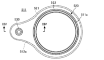
- FIG. 5 is an enlarged plan view showing a sealed portion of the metal gasket of Comparative Example 1. It is sectional drawing in the case of cutting along the XII-XII line of FIG. 5 is an enlarged plan view showing another seal portion of the metal gasket of Comparative Example 1. It is sectional drawing in the case of cutting along the XIV-XIV line of FIG. FIG. 5 is an enlarged plan view showing a portion of a seal member erroneously attached in the metal gasket of Comparative Example 1. It is sectional drawing in the case of cutting by the XVI-XVI line of FIG. It is sectional drawing which shows the joint structure of the sealing member in the metal gasket of the comparative example 2.
- FIG. 1 is a plan view showing a part of the metal gasket 1 according to the embodiment of the present invention.
- FIG. 2 is a partial cross-sectional view of the plate body 10.
- the metal gasket 1 has a plate body 10 composed of three metal plates 11, 12, and 13, and a sealing member 20 provided in a predetermined opening of the plate body 10.
- openings 16, 17, 18, and 19 are formed at positions corresponding to flow path holes (not shown) for supplying / discharging combustion gas, cooling water, and lubricating oil between the cylinder head and the cylinder block.
- a bolt insertion hole 15 is formed at an appropriate position on the plate body 10.
- the plate body 10 of the metal gasket 1 has a structure in which three metal plates of an upper plate 11, a middle plate 12, and a lower plate 13 are stacked in this order.
- the upper plate 11 faces the upper surface of the middle plate 12, and the lower plate 13 faces the lower surface of the middle plate 12.
- the upper plate 11 is arranged on the cylinder head side and the lower plate 13 is arranged on the cylinder block side.
- the upper plate 11 and the lower plate 13 are metal plates made of steel.
- the thickness of each of the upper plate 11 and the lower plate 13 is, for example, 0.4 mm.
- the surfaces of the upper plate 11 and the lower plate 13 are in contact with the processed surfaces of the cylinder head and the cylinder block, which are mating members, to absorb the roughness of the processed surfaces and to maintain the sealing property between the plates. Is coated so that it is adjacent to the cylinder via a thin coating layer.
- the upper plate 11 is formed with openings corresponding to the openings 16, 17, 18 and 19 of the metal gasket 1 by press punching.
- the lower plate 13 is also formed with openings corresponding to the openings 16, 17, 18, and 19 by press punching.
- the opening of the upper plate 11 and the opening of the lower plate 13 have the same positions and dimensions in the direction in which they overlap each other.
- the core metal 21 of the seal member 20 and the middle plate 12, which will be described later, are welded to the opening 117 of the upper plate 11 and the opening 137 of the lower plate 13 constituting the opening 17 for cooling water. Notch portions 117a and 137a for exposing the portions are formed.
- the middle plate 12 is, for example, a stainless metal plate having a thickness of 0.5 mm. Similar to the upper plate 11 and the lower plate 13, the middle plate 12 also has openings corresponding to the openings 16, 17, 18, and 19 formed by press punching.
- an opening 127 is formed in the middle plate 12 so as to coincide with the opening 117 of the upper plate 11 and the opening 137 of the lower plate 13 in the vertical direction.
- the opening 127 of the inner plate 12 has a shape and dimensions suitable for the outer edge of the core metal 21 of the seal member 20 described below.
- the middle plate 12 is formed with a half bead portion 121 so as to surround an opening (for example, opening 127A shown in FIG. 2) in which a sealing member is not provided.
- the half bead portion refers to a portion where the plate body is bent or embossed.
- the half bead portion that enhances the sealing property is formed around the opening in which the sealing member of the upper plate 11 and the lower plate 13 is not provided.
- a chevron full bead portion may be formed on the middle plate 12 or on the upper plate 11 and the lower plate 13.
- the bead-shaped seal portion including the half bead portion and the full bead portion is referred to as a "seal bead portion".
- FIG. 3 is a plan view of the seal member 20 according to the first embodiment.
- FIG. 4 is a cross-sectional view of the seal member 20 when cut along the IV-IV line of FIG.
- the sealing member 20 has, for example, a disc-shaped core metal 21 which is a stainless steel plate.
- the shape and dimensions of the outer edge of the core metal 21 conform to the shape and dimensions of the inner edge of the opening 127 of the inner plate 12 to which the sealing member 20 is joined.
- Joints 21a and 21a slightly protruding in the radial direction are formed at predetermined positions on the outer edge of the core metal 21.
- a through hole 211 for passing a fluid is formed in the substantially center of the core metal 21. It is also possible to eliminate the through hole of the core metal 21 and apply the sealing member as a blind flange for sealing the flow path between the cylinder head and the cylinder block.
- An annular elastic seal 22 is adhered to both sides of the core metal 21 so as to surround the through hole 211.
- the material of the elastic seal 22 is an elastomer having excellent heat resistance, water resistance, oil resistance and weather resistance, such as nitrile rubber (NBR), nitrile hydroxide rubber (HNBR), fluororubber (FKM) or silicone (VMQ).
- NBR nitrile rubber
- HNBR nitrile hydroxide rubber
- FKM fluororubber
- silicone silicone
- the outer peripheral surface and the inner peripheral surface of the elastic seal 22 have inclined surfaces that are inclined so as to be closer to each other as the distance from the core metal 21 increases and decreases.
- the elastic seal 22 is deformed so as to increase the width in the radial direction, but the peripheral surface of the elastic seal 22 has such an inclined surface.
- the amount of deformation and curvature of those surfaces can be suppressed to a small value.
- the elastic seal 22 is less likely to be cracked, and as a result, the sealing property and durability can be improved.
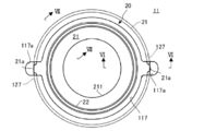
- FIG. 5 is a plan view of the metal gasket 1 according to the first embodiment, and is an enlarged view of a portion of the seal member 20.
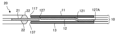
- FIG. 6 is a cross-sectional view showing a joint structure of the seal member 20 when cut along the VI-VI line of FIG.
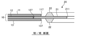
- FIG. 7 is a cross-sectional view showing a joint structure of the seal member 20 when cut along the line VII-VII of FIG.
- the joint portion 21a formed on the outer edge of the core metal 21 is butt-welded to the inner edge of the opening 127 of the middle plate 12.
- the welded portion 31 between the core metal 21 and the middle plate 12 is exposed to the outside through the cutout portions 117a and 137a of the upper and lower metal plates 11 and 13.
- the core metal 21 of the seal member 20 and the middle plate 12 are preferably seam welded continuously by a laser welding method, but may be spot welded intermittently. Further, it is preferable that the thickness of the middle plate 12 and the core metal 21 are the same, and the surfaces thereof are the same. As a result, it is possible to prevent unnecessary strain and internal stress from being generated at the welded portion when the metal gasket 1 is compressed.
- the metal gasket 2 according to the present embodiment has a plate body 10 having a structure in which three metal plates of an upper plate 11, a middle plate 12, and a lower plate 13 are stacked in this order, and a core metal 21.
- a seal member 20 having an elastic seal 22 is provided, and the core metal 21 of the seal member 20 is welded to the opening 127 of the inner plate 12.
- FIG. 8 is a plan view of the metal gasket 2 according to the second embodiment, and is an enlarged view of a portion of the seal member 20.
- FIG. 9 is a cross-sectional view showing a joint structure of the seal member 20 when cut along the line IX-IX of FIG.
- FIG. 10 is a cross-sectional view showing a joint structure of the seal member 20 when cut by the X-X line of FIG.
- the bonding structure of the sealing member 20 to the plate body 10 is different from that of the first embodiment described above.
- at least a part of the outer edge of the core metal 21 of the seal member 20 is an overlapping portion 21b extending to the peripheral edge portion 127a of the opening 127 of the middle plate 12. .. Then, the overlapping portion 21b of the seal member 20 and the opening peripheral edge portion 127a of the middle plate 12 are overlapped and welded. The lap welded portion 32 is exposed to the outside through the cutout portions 117a and 137a of the upper and lower metal plates 11 and 13.
- the welding of the core metal 21 and the middle plate 12 is preferably spot welding by laser welding or electric resistance welding. Further, the end portion of the core metal 21 may be joined to the middle plate 12 by fillet welding. In the case of fillet welding, they can be joined by more general arc welding in addition to laser welding.
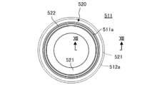
- FIG. 11 is an enlarged plan view showing a portion of the seal member 520 in the metal gasket of Comparative Example 1.
- FIG. 12 is a cross-sectional view showing a mounting structure of the seal member 520 when cut along the line XII-XII of FIG.
- the metal gasket according to Comparative Example 1 has a plate body 510 in which three metal plates 511, 512, and 513 are stacked. At the peripheral edge of the opening where the sealing member 520 is provided, all or at least a part of the opening edges 511a and 513a of the upper plate 511 and the lower plate 513 extend toward the center of the opening edge 512a of the middle plate 512. ..
- the plate body 510 has a groove defined by the extending portions of the upper and lower plates 511 and 513 at the peripheral edge of the opening.
- the seal member 520 is attached to the opening of the plate body 510 in a state where the flange of the core metal 521 is fitted in the groove, that is, it is sandwiched between the upper and lower plates 511 and 513.
- the core metal 521 of the seal member 520 is sandwiched between the upper plate 511 and the lower plate 513 and fitted.
- a joining means 530 such as a rivet for joining the upper and lower plates 511 and 513 in the vicinity of the seal member 520 or the opening is required (FIG. 13, FIG. 14).
- the core metal 21 of the sealing member 20 is fixed to the opening of the middle plate 12 by welding. Therefore, a joining means such as the above-mentioned rivet is not required. Therefore, the structure and the assembling process of the joint portion of the seal member 20 to the plate body 10 can be simplified as compared with the conventional case.
- Comparative Example 1 there is a problem that it is not possible to visually inspect whether the seal member 520 is correctly fitted between the upper and lower plates 511 and 513 after assembly. If the sealing member 520 is arranged in the wrong direction as shown in FIG. 15, the core metal 521 rides on the middle plate 512 and the sealing property is impaired (see FIG. 16).
- the welded portions 31 and 32 of the seal member 20 are exposed to the outside through the cutout portions 117a and 137a of the upper and lower metal plates 11 and 13. .. Therefore, it is possible to visually inspect the joint state of the seal member 20, and it is possible to prevent the shipment of products having assembly mistakes, welding defects, and the like. Therefore, the reliability of the product can be improved as compared with the conventional case.
- FIG. 17 is a cross-sectional view showing a coupling structure of the sealing member 520 of the metal gasket according to Comparative Example 2.
- a step portion 541 is provided along the open end of one plate main body 540.
- the flange 521a of the core metal 521 is welded to the step portion 541 of the seal member 520.
- the plate body 540 is composed of one metal plate. Therefore, there is a problem that the thickness of the plate body 540 is limited to the standard thickness material available on the market.
- the plate body 10 is composed of three metal plates 11, 12, and 13. Therefore, as compared with Comparative Example 2, it can be said that the degree of freedom in selecting the thickness and the combination of materials when designing the plate body 10 is high.
- the metal gasket of Comparative Example 2 cannot form a seal bead portion due to the structure of a single plate.
- a half bead portion or a full bead portion can be formed on the middle plate 12 or the upper and lower plates 11 and 13. Therefore, the adhesion to the cylinder head and the cylinder block is increased, and the sealing property and reliability can be improved as compared with Comparative Example 2.
Landscapes
- Engineering & Computer Science (AREA)
- General Engineering & Computer Science (AREA)
- Mechanical Engineering (AREA)
- Chemical & Material Sciences (AREA)
- Combustion & Propulsion (AREA)
- Gasket Seals (AREA)
Priority Applications (2)
| Application Number | Priority Date | Filing Date | Title |
|---|---|---|---|
| CN202080039213.9A CN113874616B (zh) | 2019-05-31 | 2020-04-17 | 金属衬垫 |
| JP2021522701A JP7417603B2 (ja) | 2019-05-31 | 2020-04-17 | メタルガスケット |
Applications Claiming Priority (2)
| Application Number | Priority Date | Filing Date | Title |
|---|---|---|---|
| JP2019-102481 | 2019-05-31 | ||
| JP2019102481 | 2019-05-31 |
Publications (1)
| Publication Number | Publication Date |
|---|---|
| WO2020241113A1 true WO2020241113A1 (ja) | 2020-12-03 |
Family
ID=73553986
Family Applications (1)
| Application Number | Title | Priority Date | Filing Date |
|---|---|---|---|
| PCT/JP2020/016920 Ceased WO2020241113A1 (ja) | 2019-05-31 | 2020-04-17 | メタルガスケット |
Country Status (3)
| Country | Link |
|---|---|
| JP (1) | JP7417603B2 (https=) |
| CN (1) | CN113874616B (https=) |
| WO (1) | WO2020241113A1 (https=) |
Cited By (3)
| Publication number | Priority date | Publication date | Assignee | Title |
|---|---|---|---|---|
| JP2023172209A (ja) * | 2022-05-23 | 2023-12-06 | 岡安ゴム株式会社 | パッキン |
| JP2023172210A (ja) * | 2022-05-23 | 2023-12-06 | 岡安ゴム株式会社 | パッキンの製造方法 |
| JP7854708B2 (ja) | 2022-05-23 | 2026-05-07 | 岡安ゴム株式会社 | パッキンの製造方法 |
Citations (2)
| Publication number | Priority date | Publication date | Assignee | Title |
|---|---|---|---|---|
| JP2008523326A (ja) * | 2004-12-10 | 2008-07-03 | エルリングクリンガー アーゲー | 平形ガスケット |
| JP2012237388A (ja) * | 2011-05-12 | 2012-12-06 | Toyota Motor Corp | シリンダヘッドガスケット |
Family Cites Families (10)
| Publication number | Priority date | Publication date | Assignee | Title |
|---|---|---|---|---|
| JP3266630B2 (ja) * | 1991-10-11 | 2002-03-18 | 大豊工業株式会社 | 金属ガスケットの製造方法 |
| JP3118043B2 (ja) * | 1991-10-24 | 2000-12-18 | 大豊工業株式会社 | 金属ガスケット |
| JPH05340476A (ja) * | 1992-06-09 | 1993-12-21 | Japan Metal Gasket Co Ltd | 金属ガスケット |
| DE19606382A1 (de) * | 1996-02-21 | 1997-09-04 | Elringklinger Gmbh | Zylinderkopfdichtung mit einer mehrere Metallblechlagen aufweisenden Dichtungsplatte |
| JP2004340254A (ja) * | 2003-05-15 | 2004-12-02 | Uchiyama Mfg Corp | シリンダヘッドガスケット |
| JP4246726B2 (ja) * | 2005-10-21 | 2009-04-02 | 石川ガスケット株式会社 | 金属積層型ガスケット |
| KR20110003044A (ko) * | 2009-07-03 | 2011-01-11 | (주)지에스티산업 | 실린더 헤드 개스킷 |
| CN202065087U (zh) * | 2011-05-09 | 2011-12-07 | 锦州光和密封实业有限公司 | 发动机气缸垫 |
| CN202082002U (zh) * | 2011-06-08 | 2011-12-21 | 锦州光和密封实业有限公司 | 柴油机单层板气缸垫 |
| JP2018179033A (ja) * | 2017-04-04 | 2018-11-15 | いすゞ自動車株式会社 | シール部材 |
-
2020
- 2020-04-17 CN CN202080039213.9A patent/CN113874616B/zh not_active Expired - Fee Related
- 2020-04-17 WO PCT/JP2020/016920 patent/WO2020241113A1/ja not_active Ceased
- 2020-04-17 JP JP2021522701A patent/JP7417603B2/ja active Active
Patent Citations (2)
| Publication number | Priority date | Publication date | Assignee | Title |
|---|---|---|---|---|
| JP2008523326A (ja) * | 2004-12-10 | 2008-07-03 | エルリングクリンガー アーゲー | 平形ガスケット |
| JP2012237388A (ja) * | 2011-05-12 | 2012-12-06 | Toyota Motor Corp | シリンダヘッドガスケット |
Cited By (4)
| Publication number | Priority date | Publication date | Assignee | Title |
|---|---|---|---|---|
| JP2023172209A (ja) * | 2022-05-23 | 2023-12-06 | 岡安ゴム株式会社 | パッキン |
| JP2023172210A (ja) * | 2022-05-23 | 2023-12-06 | 岡安ゴム株式会社 | パッキンの製造方法 |
| JP7854708B2 (ja) | 2022-05-23 | 2026-05-07 | 岡安ゴム株式会社 | パッキンの製造方法 |
| JP7855195B2 (ja) | 2022-05-23 | 2026-05-08 | 岡安ゴム株式会社 | パッキン |
Also Published As
| Publication number | Publication date |
|---|---|
| CN113874616A (zh) | 2021-12-31 |
| JP7417603B2 (ja) | 2024-01-18 |
| JPWO2020241113A1 (https=) | 2020-12-03 |
| CN113874616B (zh) | 2024-08-09 |
Similar Documents
| Publication | Publication Date | Title |
|---|---|---|
| JP3460819B2 (ja) | ヘッドガスケット | |
| JP6246797B2 (ja) | 金属ガスケット | |
| EP2467627B1 (en) | Cylinder head gasket assembly | |
| KR20020075289A (ko) | 금속 가스켓 | |
| KR101194476B1 (ko) | 레이저 용접된 다층식 강철 가스켓 조립체 | |
| US9291121B2 (en) | Cylinder head gasket | |
| US6779800B2 (en) | Head gasket | |
| JP2007113721A (ja) | 金属積層型ガスケット | |
| JP5136808B2 (ja) | シリンダヘッドガスケットとその製造方法 | |
| EP0544951A1 (en) | Gasket | |
| JPWO2010007911A1 (ja) | シリンダヘッドガスケット | |
| JP7417603B2 (ja) | メタルガスケット | |
| JP2009503404A (ja) | ガスケットアセンブリ | |
| JP7311183B1 (ja) | シール連結体およびガスケット | |
| CN101163909A (zh) | 金属垫片 | |
| US7690657B2 (en) | Flat gasket | |
| JPH0464777A (ja) | 金属ガスケット | |
| JP2017198288A (ja) | ガスケット | |
| KR20110003044A (ko) | 실린더 헤드 개스킷 | |
| JP6398147B2 (ja) | シリンダヘッドガスケット | |
| JP2990289B2 (ja) | 金属ガスケット | |
| JP6677301B2 (ja) | ガスケット | |
| JP2004278710A (ja) | シリンダーヘッド用メタルガスケット | |
| JPH0488264A (ja) | 金属ガスケット | |
| JP2010065807A (ja) | シリンダヘッドガスケット |
Legal Events
| Date | Code | Title | Description |
|---|---|---|---|
| 121 | Ep: the epo has been informed by wipo that ep was designated in this application |
Ref document number: 20812586 Country of ref document: EP Kind code of ref document: A1 |
|
| ENP | Entry into the national phase |
Ref document number: 2021522701 Country of ref document: JP Kind code of ref document: A |
|
| NENP | Non-entry into the national phase |
Ref country code: DE |
|
| 122 | Ep: pct application non-entry in european phase |
Ref document number: 20812586 Country of ref document: EP Kind code of ref document: A1 |