WO2020235396A1 - 障害物検出装置および障害物検出方法 - Google Patents
障害物検出装置および障害物検出方法 Download PDFInfo
- Publication number
- WO2020235396A1 WO2020235396A1 PCT/JP2020/019004 JP2020019004W WO2020235396A1 WO 2020235396 A1 WO2020235396 A1 WO 2020235396A1 JP 2020019004 W JP2020019004 W JP 2020019004W WO 2020235396 A1 WO2020235396 A1 WO 2020235396A1
- Authority
- WO
- WIPO (PCT)
- Prior art keywords
- target
- probability
- obstacle detection
- detection device
- peripheral monitoring
- Prior art date
- Legal status (The legal status is an assumption and is not a legal conclusion. Google has not performed a legal analysis and makes no representation as to the accuracy of the status listed.)
- Ceased
Links
Images


Classifications
-
- G—PHYSICS
- G01—MEASURING; TESTING
- G01S—RADIO DIRECTION-FINDING; RADIO NAVIGATION; DETERMINING DISTANCE OR VELOCITY BY USE OF RADIO WAVES; LOCATING OR PRESENCE-DETECTING BY USE OF THE REFLECTION OR RERADIATION OF RADIO WAVES; ANALOGOUS ARRANGEMENTS USING OTHER WAVES
- G01S13/00—Systems using the reflection or reradiation of radio waves, e.g. radar systems; Analogous systems using reflection or reradiation of waves whose nature or wavelength is irrelevant or unspecified
- G01S13/88—Radar or analogous systems specially adapted for specific applications
- G01S13/93—Radar or analogous systems specially adapted for specific applications for anti-collision purposes
- G01S13/931—Radar or analogous systems specially adapted for specific applications for anti-collision purposes of land vehicles
-
- G—PHYSICS
- G01—MEASURING; TESTING
- G01S—RADIO DIRECTION-FINDING; RADIO NAVIGATION; DETERMINING DISTANCE OR VELOCITY BY USE OF RADIO WAVES; LOCATING OR PRESENCE-DETECTING BY USE OF THE REFLECTION OR RERADIATION OF RADIO WAVES; ANALOGOUS ARRANGEMENTS USING OTHER WAVES
- G01S13/00—Systems using the reflection or reradiation of radio waves, e.g. radar systems; Analogous systems using reflection or reradiation of waves whose nature or wavelength is irrelevant or unspecified
- G01S13/86—Combinations of radar systems with non-radar systems, e.g. sonar, direction finder
-
- G—PHYSICS
- G01—MEASURING; TESTING
- G01S—RADIO DIRECTION-FINDING; RADIO NAVIGATION; DETERMINING DISTANCE OR VELOCITY BY USE OF RADIO WAVES; LOCATING OR PRESENCE-DETECTING BY USE OF THE REFLECTION OR RERADIATION OF RADIO WAVES; ANALOGOUS ARRANGEMENTS USING OTHER WAVES
- G01S13/00—Systems using the reflection or reradiation of radio waves, e.g. radar systems; Analogous systems using reflection or reradiation of waves whose nature or wavelength is irrelevant or unspecified
- G01S13/87—Combinations of radar systems, e.g. primary radar and secondary radar
- G01S13/878—Combination of several spaced transmitters or receivers of known location for determining the position of a transponder or a reflector
-
- G—PHYSICS
- G01—MEASURING; TESTING
- G01S—RADIO DIRECTION-FINDING; RADIO NAVIGATION; DETERMINING DISTANCE OR VELOCITY BY USE OF RADIO WAVES; LOCATING OR PRESENCE-DETECTING BY USE OF THE REFLECTION OR RERADIATION OF RADIO WAVES; ANALOGOUS ARRANGEMENTS USING OTHER WAVES
- G01S15/00—Systems using the reflection or reradiation of acoustic waves, e.g. sonar systems
- G01S15/88—Sonar systems specially adapted for specific applications
- G01S15/93—Sonar systems specially adapted for specific applications for anti-collision purposes
- G01S15/931—Sonar systems specially adapted for specific applications for anti-collision purposes of land vehicles
-
- G—PHYSICS
- G01—MEASURING; TESTING
- G01S—RADIO DIRECTION-FINDING; RADIO NAVIGATION; DETERMINING DISTANCE OR VELOCITY BY USE OF RADIO WAVES; LOCATING OR PRESENCE-DETECTING BY USE OF THE REFLECTION OR RERADIATION OF RADIO WAVES; ANALOGOUS ARRANGEMENTS USING OTHER WAVES
- G01S7/00—Details of systems according to groups G01S13/00, G01S15/00, G01S17/00
- G01S7/02—Details of systems according to groups G01S13/00, G01S15/00, G01S17/00 of systems according to group G01S13/00
- G01S7/28—Details of pulse systems
- G01S7/285—Receivers
- G01S7/295—Means for transforming co-ordinates or for evaluating data, e.g. using computers
- G01S7/2955—Means for determining the position of the radar coordinate system for evaluating the position data of the target in another coordinate system
-
- G—PHYSICS
- G01—MEASURING; TESTING
- G01S—RADIO DIRECTION-FINDING; RADIO NAVIGATION; DETERMINING DISTANCE OR VELOCITY BY USE OF RADIO WAVES; LOCATING OR PRESENCE-DETECTING BY USE OF THE REFLECTION OR RERADIATION OF RADIO WAVES; ANALOGOUS ARRANGEMENTS USING OTHER WAVES
- G01S7/00—Details of systems according to groups G01S13/00, G01S15/00, G01S17/00
- G01S7/02—Details of systems according to groups G01S13/00, G01S15/00, G01S17/00 of systems according to group G01S13/00
- G01S7/41—Details of systems according to groups G01S13/00, G01S15/00, G01S17/00 of systems according to group G01S13/00 using analysis of echo signal for target characterisation; Target signature; Target cross-section
-
- G—PHYSICS
- G01—MEASURING; TESTING
- G01S—RADIO DIRECTION-FINDING; RADIO NAVIGATION; DETERMINING DISTANCE OR VELOCITY BY USE OF RADIO WAVES; LOCATING OR PRESENCE-DETECTING BY USE OF THE REFLECTION OR RERADIATION OF RADIO WAVES; ANALOGOUS ARRANGEMENTS USING OTHER WAVES
- G01S7/00—Details of systems according to groups G01S13/00, G01S15/00, G01S17/00
- G01S7/48—Details of systems according to groups G01S13/00, G01S15/00, G01S17/00 of systems according to group G01S17/00
- G01S7/4808—Evaluating distance, position or velocity data
-
- G—PHYSICS
- G08—SIGNALLING
- G08G—TRAFFIC CONTROL SYSTEMS
- G08G1/00—Traffic control systems for road vehicles
- G08G1/16—Anti-collision systems
-
- G—PHYSICS
- G01—MEASURING; TESTING
- G01S—RADIO DIRECTION-FINDING; RADIO NAVIGATION; DETERMINING DISTANCE OR VELOCITY BY USE OF RADIO WAVES; LOCATING OR PRESENCE-DETECTING BY USE OF THE REFLECTION OR RERADIATION OF RADIO WAVES; ANALOGOUS ARRANGEMENTS USING OTHER WAVES
- G01S17/00—Systems using the reflection or reradiation of electromagnetic waves other than radio waves, e.g. lidar systems
- G01S17/87—Combinations of systems using electromagnetic waves other than radio waves
-
- G—PHYSICS
- G01—MEASURING; TESTING
- G01S—RADIO DIRECTION-FINDING; RADIO NAVIGATION; DETERMINING DISTANCE OR VELOCITY BY USE OF RADIO WAVES; LOCATING OR PRESENCE-DETECTING BY USE OF THE REFLECTION OR RERADIATION OF RADIO WAVES; ANALOGOUS ARRANGEMENTS USING OTHER WAVES
- G01S17/00—Systems using the reflection or reradiation of electromagnetic waves other than radio waves, e.g. lidar systems
- G01S17/88—Lidar systems specially adapted for specific applications
- G01S17/93—Lidar systems specially adapted for specific applications for anti-collision purposes
- G01S17/931—Lidar systems specially adapted for specific applications for anti-collision purposes of land vehicles
-
- G—PHYSICS
- G01—MEASURING; TESTING
- G01S—RADIO DIRECTION-FINDING; RADIO NAVIGATION; DETERMINING DISTANCE OR VELOCITY BY USE OF RADIO WAVES; LOCATING OR PRESENCE-DETECTING BY USE OF THE REFLECTION OR RERADIATION OF RADIO WAVES; ANALOGOUS ARRANGEMENTS USING OTHER WAVES
- G01S13/00—Systems using the reflection or reradiation of radio waves, e.g. radar systems; Analogous systems using reflection or reradiation of waves whose nature or wavelength is irrelevant or unspecified
- G01S13/88—Radar or analogous systems specially adapted for specific applications
- G01S13/93—Radar or analogous systems specially adapted for specific applications for anti-collision purposes
- G01S13/931—Radar or analogous systems specially adapted for specific applications for anti-collision purposes of land vehicles
- G01S2013/9323—Alternative operation using light waves
-
- G—PHYSICS
- G01—MEASURING; TESTING
- G01S—RADIO DIRECTION-FINDING; RADIO NAVIGATION; DETERMINING DISTANCE OR VELOCITY BY USE OF RADIO WAVES; LOCATING OR PRESENCE-DETECTING BY USE OF THE REFLECTION OR RERADIATION OF RADIO WAVES; ANALOGOUS ARRANGEMENTS USING OTHER WAVES
- G01S13/00—Systems using the reflection or reradiation of radio waves, e.g. radar systems; Analogous systems using reflection or reradiation of waves whose nature or wavelength is irrelevant or unspecified
- G01S13/88—Radar or analogous systems specially adapted for specific applications
- G01S13/93—Radar or analogous systems specially adapted for specific applications for anti-collision purposes
- G01S13/931—Radar or analogous systems specially adapted for specific applications for anti-collision purposes of land vehicles
- G01S2013/9327—Sensor installation details
- G01S2013/93271—Sensor installation details in the front of the vehicles
-
- G—PHYSICS
- G01—MEASURING; TESTING
- G01S—RADIO DIRECTION-FINDING; RADIO NAVIGATION; DETERMINING DISTANCE OR VELOCITY BY USE OF RADIO WAVES; LOCATING OR PRESENCE-DETECTING BY USE OF THE REFLECTION OR RERADIATION OF RADIO WAVES; ANALOGOUS ARRANGEMENTS USING OTHER WAVES
- G01S13/00—Systems using the reflection or reradiation of radio waves, e.g. radar systems; Analogous systems using reflection or reradiation of waves whose nature or wavelength is irrelevant or unspecified
- G01S13/88—Radar or analogous systems specially adapted for specific applications
- G01S13/93—Radar or analogous systems specially adapted for specific applications for anti-collision purposes
- G01S13/931—Radar or analogous systems specially adapted for specific applications for anti-collision purposes of land vehicles
- G01S2013/9327—Sensor installation details
- G01S2013/93276—Sensor installation details in the windshield area
-
- G—PHYSICS
- G01—MEASURING; TESTING
- G01S—RADIO DIRECTION-FINDING; RADIO NAVIGATION; DETERMINING DISTANCE OR VELOCITY BY USE OF RADIO WAVES; LOCATING OR PRESENCE-DETECTING BY USE OF THE REFLECTION OR RERADIATION OF RADIO WAVES; ANALOGOUS ARRANGEMENTS USING OTHER WAVES
- G01S7/00—Details of systems according to groups G01S13/00, G01S15/00, G01S17/00
- G01S7/48—Details of systems according to groups G01S13/00, G01S15/00, G01S17/00 of systems according to group G01S17/00
- G01S7/4802—Details of systems according to groups G01S13/00, G01S15/00, G01S17/00 of systems according to group G01S17/00 using analysis of echo signal for target characterisation; Target signature; Target cross-section
Definitions
- This disclosure relates to a technique for detecting obstacles.
- a device When detecting an obstacle around the vehicle, a device is used that transmits an exploration wave from the sensor to the vicinity of the vehicle and receives the reflected wave from the target to detect the target.
- targets There are two types of targets: small targets that vehicles can overcome and normal targets that cannot be overcome. For small targets, it is not always necessary to take measures such as issuing an alarm.
- the height of the target is calculated based on the beam irradiation angle from the sensor and the detection distance of the target, and the detected target is detected immediately before the detection.
- a technique for determining a small target if the height of the target is below the threshold value is disclosed.
- the signal intensity of the beam from the sensor becomes weaker as it deviates from the center of the beam, so the reflection intensity from a small target located off the center of the beam changes significantly as the vehicle moves. I am using.
- Patent Document 1 As a result of detailed examination by the inventor, the following problems have been found in the prior art described in Patent Document 1. That is, in the prior art, since it is necessary to find the timing at which detection becomes impossible, it is necessary to continuously detect the target to be determined. However, a small object such as a parking block generally has a weak signal strength and unstable detection by a sensor, so that continuous detection, that is, stable tracking is difficult. Moreover, it is difficult to accurately detect the distance to the target from such a weak signal. As a result, in the prior art, it was not possible to make a highly reliable determination as to whether or not the object is a small object.
- One aspect of the present disclosure is to provide a technique for improving the detection accuracy of a small object.
- an obstacle detection device which includes a result acquisition unit, a probability calculation unit, and a type determination unit.
- the result acquisition unit is configured to irradiate the exploration wave to a preset exploration range and repeatedly acquire the measurement result from the peripheral monitoring sensor that measures the distance to the reflection point reflecting the exploration wave and the horizontal direction.
- the probability calculation unit is configured to calculate the detection probability for each of the reflection points according to the measurement result acquired by the result acquisition unit.
- the type determination unit is configured to determine the type of the target to which the reflection point belongs according to the detection probability calculated by the probability calculation unit.
- One aspect of the present disclosure is an obstacle detection method executed by a computer.
- the computer repeatedly acquires the measurement result from the peripheral monitoring sensor that irradiates the exploration wave to the preset exploration range and measures the distance to the reflection point reflecting the exploration wave and the horizontal direction.
- the computer calculates the detection probability for each of the reflection points according to the acquired measurement result.
- the computer determines the type of target to which the reflection point belongs according to the calculated detection probability.
- the type of the target is determined by using the detection probability that reflects the difficulty of detection, which is a characteristic of the small target, instead of using the reflection intensity that changes greatly depending on the environment. Therefore, it is possible to improve the detection accuracy of a small object whose reflection point is intermittently detected and tracking is difficult.
- the obstacle detection device 1 shown in FIG. 1 is mounted on a vehicle and detects various obstacles existing around the vehicle.
- the obstacle detection device 1 includes a signal processing unit 10.
- the obstacle detection device 1 may include a peripheral monitoring sensor 2, a GNSS receiver 3, a map database 4, and an in-vehicle sensor group 5.
- the vehicle equipped with the obstacle detection device 1 is referred to as a own vehicle.
- the peripheral monitoring sensor 2 includes a laser radar or a millimeter wave radar. As shown in FIG. 2, the peripheral monitoring sensor 2 is installed in or around the front bumper of the own vehicle, and the search range is within a predetermined angle in a horizontal plane set around the forward direction of the own vehicle.
- the installation position of the peripheral monitoring sensor 2 is not limited to this, and may be installed around the rearview mirror or the like. Further, it may be installed so that the rear or side of the vehicle is the exploration range.
- the peripheral monitoring sensor 2 scans the exploration range in the horizontal direction for each unit angle, and is based on the round-trip time from when the exploration wave is irradiated until when the reflected wave from the object irradiated with the exploration wave is received. Calculate the distance to the reflection point that reflected the exploration wave.
- the peripheral monitoring sensor 2 executes scanning every preset measurement cycle, and uses the scanning angle and the distance calculated at the scanning angle to use a relative coordinate system with the mounting position of the peripheral monitoring sensor 2 as the origin. Generates reflection point information indicating the position of the reflection point with.
- the GNSS receiver 3 receives the transmitted radio wave from the artificial satellite for GNSS, and generates the own vehicle position information representing the position of the own vehicle in the absolute coordinate system using latitude and longitude.
- GNSS is an abbreviation for Global Navigation Satellite System.
- the map database 4 is a storage device that stores map data expressed using an absolute coordinate system.
- the map data is represented by nodes set at intersections on actual roads and links connecting the nodes.
- each node is associated with attribute information including road width and number of lanes.
- the in-vehicle sensor group 5 detects physical quantities related to the behavior of the vehicle, such as a vehicle speed sensor, a yaw rate sensor, and a steering angle sensor.
- the signal processing unit 10 includes a microcomputer having a CPU 11 and a semiconductor memory (hereinafter, memory 12) such as RAM, ROM, and flash memory.
- memory 12 such as RAM, ROM, and flash memory.
- the signal processing unit 10 at least executes the grid map update process and the obstacle detection process.
- an area for recording the target information and an area for recording the grid map are prepared.
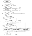
- the grid map update process will be described with reference to the flowchart shown in FIG.
- the grid map update process is started every measurement cycle.
- the measurement cycle is a cycle in which the peripheral monitoring sensor 2 scans the exploration range.
- the signal processing unit 10 acquires the current position and traveling direction of the own vehicle from the GNSS receiver 3, and updates the range of the grid map to be processed according to the acquired information.
- a grid map has cells that are compartments on the absolute coordinate system that are uniformly sized by the grid. Each cell is given an identification number that identifies the cell.
- the signal processing unit 10 updates the range of the grid map to be processed so that at least the cells corresponding to the search range of the peripheral monitoring sensor 2 are included based on the current position of the own vehicle. .. Since the grid map uses an absolute coordinate system, the positions of individual cells are invariant with respect to the movement of the vehicle.
- the signal processing unit 10 acquires the reflection point information which is the result of scanning the search range from the peripheral monitoring sensor 2.
- the signal processing unit 10 selects one of the reflection point information acquired from the peripheral monitoring sensor 2 as the target information, which is the reflection point information in which the processes of S140 to S150 described below are not executed. ..
- the signal processing unit 10 converts the target information represented by the relative coordinates into absolute coordinates, and specifies a cell (hereinafter, target cell) on the grid map corresponding to the position represented by the target information.
- the signal processing unit 10 records the information in which the target information is associated with the target cell in the memory 12 as the target information.
- the target information recorded in the memory 12 includes "time”, “sensor position”, “target number”, “distance”, and “cell coordinates”.
- the “time” is information that identifies the measurement cycle in which the target information is recorded.
- the “sensor position” is the position of the peripheral monitoring sensor 2, and here, the current position of the own vehicle acquired from the GNSS receiver 3 is used.
- the “target number” is information for identifying individual reflection point information generated by the peripheral monitoring sensor 2.
- the “target position” is information indicating the direction in which the target indicated in the target information exists.
- the “distance” is information representing the distance to the target indicated in the target information.
- the “cell coordinates” are information representing the absolute position of the target cell specified in S140.
- the memory 12 is managed so that target information for a predetermined period in the past is recorded, and old information that is no longer needed is overwritten in order.
- S110 corresponds to the position acquisition unit and S120 corresponds to the result acquisition unit.
- the obstacle detection process is executed at each preset determination timing.
- M is a positive integer
- m 1 to M
- the timing for each m measurement cycle is set as the determination timing.
- the signal processing unit 10 selects a target cell to be processed from the latest grid map updated in the clip map update process. At this time, the cells on the grid map corresponding to the search range of the peripheral monitoring sensor 2 are processed.
- the present invention is not limited to this, and the entire grid map updated in S110 may be processed.
- the memory 12 stores the detection probability P calculated at the determination timing from this time to X times before for each cell.
- the signal processing unit 10 resets the count values C1, C2, and C3 associated with the target cells used in the processing of S250 and S270 described later to 0, and proceeds to the processing in S280.
- the signal processing unit 10 executes a type determination process for determining the type of the target existing in the target cell by using the detection probability P of the target cell recorded in the memory 12.
- a normal target is a target that a vehicle cannot overcome.
- a small target is a target that is smaller in height in the height direction than a normal target and can be overcome by a vehicle.
- the signal processing unit 10 determines whether or not the determination result in the type determination process is a small target, and if it is determined to be a small target, the processing shifts to S270 and the small object is determined. If it is determined that it is not a target, the process shifts to S280.
- the signal processing unit 10 executes a position determination process for determining the height position of the small object using the detection probability P of the target cell recorded in the memory 12, and advances the process to S280.
- the signal processing unit 10 determines whether or not the processing of S220 to S270 has been executed for all the cells to be processed. When it is determined that there are unprocessed cells, the signal processing unit 10 returns the processing to S210, and when it is determined that the processing has been executed for all the cells, the signal processing unit 10 ends the processing.
- S220 corresponds to the probability calculation unit and S250 corresponds to the type determination unit.
- the signal processing unit 10 determines whether or not the detection probability P calculated in S220 above for the target cell is larger than the preset first threshold value TH1. When the signal processing unit 10 determines that P> TH1, the process shifts to S320, and when it determines that P ⁇ TH1, the process shifts to S330.
- the signal processing unit 10 increments the count value C1 indicating the number of times that P> TH1 is continuously determined, and advances the processing to S340.
- the signal processing unit 10 resets the count value C1 to 0 and advances the processing to S340.
- the signal processing unit 10 determines whether or not the count value C1 is equal to or higher than the preset threshold value N1.
- the signal processing unit 10 determines that C1 ⁇ N1, that is, when it determines that P> TH1 at all of the past N1 determination timings, it shifts the processing to S350, and when it determines that C1 ⁇ N1. The process shifts to S410.
- the signal processing unit 10 determines whether or not the detection probability P recorded for the target cell is smaller than the preset second threshold value TH2, and if it is determined that P ⁇ TH2, the processing shifts to S360. If it is determined that P ⁇ TH2, the process shifts to S370.
- the second threshold value TH2 is set to a value larger than the first threshold value TH1.
- the signal processing unit 10 increments the count value C2 representing the number of times that P ⁇ TH2 is continuously determined, and advances the processing to S380.
- the signal processing unit 10 resets the count value C2 to 0 and advances the processing to S370.
- the signal processing unit 10 determines whether or not the count value C2 is equal to or higher than the preset threshold value N2.
- the signal processing unit 10 determines that C2 ⁇ N2, that is, when it determines that P> TH2 at all of the past N2 determination timings, it shifts the processing to S390, and when it determines that C2 ⁇ N2, The process shifts to S400.
- the threshold values N1 and N2 may be the same value or different values.
- the signal processing unit 10 outputs a determination result that the target type is a small target, and ends the processing. That is, when the state in which the detection probability P is TH1 ⁇ P ⁇ TH2 continues to some extent, it is determined that the target is a small target.
- the signal processing unit 10 outputs a determination result that the target type is a normal target, and ends the process. That is, when the state in which P ⁇ TH2 is detected intermittently or continuously, it is determined to be a normal target.
- the signal processing unit 10 outputs a determination result that the target type is a virtual image, and ends the processing. That is, when the state where P> TH1 is sporadically detected, it is determined to be a virtual image.
- the detection probability P is a value between the normal target and the virtual image. Therefore, the threshold values TH1 and TH2 may be experimentally set to values that can distinguish them.
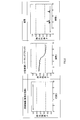
- the graph of FIG. 8 shows the time of the detection probability P calculated when the vehicle equipped with the peripheral monitoring sensor 2 approaches the target at a constant speed using the side surface of the vehicle as a normal target and the parking block as a small target. It is a transition.
- the virtual image is the result of measurement in the absence of a target.
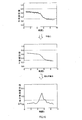
- the signal processing unit 10 executes a process of flattening the time transition of the detection probability P of the target cell.
- This process is a process that realizes the function of a so-called low-pass filter. For example, it is conceivable to calculate and use the average value of the detection probabilities P for a plurality of times in the past. As a result, the graph showing the time transition of the detection probability P calculated for each determination timing shown in the upper part of FIG. 10 is smoothed like the graph shown in the middle part of FIG.
- the signal processing unit 10 calculates the rate of change ⁇ P of the detection probability P with respect to the distance d. This is because the rate of change ⁇ P does not depend on the moving speed of the own vehicle but depends on the distance to the target. As a result, as the graph shown in the middle part of FIG. 10, the graph shown in the lower part of FIG. 10 showing the slope of the graph is obtained. Since the case where the own vehicle moves at a constant speed is shown here, the time on the horizontal axis in the graph of FIG. 10 corresponds to the distance.
- the signal processing unit 10 determines whether or not the rate of change ⁇ P is larger than the preset third threshold value TH3, and if it is determined that ⁇ P> TH3, the processing shifts to S540, and ⁇ P ⁇ TH3. If it is determined, the process shifts to S550.
- the signal processing unit 10 increments the count value C3 representing the number of times that ⁇ P> TH3 is continuously determined, and advances the processing to S560.
- the signal processing unit 10 resets the count value C3 to 0 and advances the processing to S560.
- the signal processing unit 10 determines whether or not the count value C3 is equal to or higher than the preset threshold value N3.
- the processing shifts to S570, and when it determines that C3 ⁇ N3, the signal processing unit 10 shifts the processing to S570.
- the process shifts to S580.
- the threshold value N3 may be the same value as the threshold values N1 and N2, or may be a different value.
- the signal processing unit 10 outputs a determination result that the small target is located above or below, and ends the processing.
- the signal processing unit 10 outputs a determination result that the small target is located in front of the target, and ends the processing.
- the small target when the small target is located in the front direction with respect to the peripheral monitoring sensor 2, that is, at the same height as the peripheral monitoring sensor 2, the small target always has a beam regardless of the distance from the peripheral monitoring sensor 2. Located within range. Therefore, the detection probability P does not change significantly, and the rate of change ⁇ P is close to zero.
- the small target is located above or below the front direction of the peripheral monitoring sensor 2, when the distance from the peripheral monitoring sensor 2 is large, the beam is widened, so that the entire small target is within the beam range. It exists and is detected with a detection probability P according to the distance. Also in this case, the rate of change ⁇ P of the detection probability after smoothing is a small value close to 0.
- the third threshold value TH3 is set to a value that can detect an increase in the rate of change ⁇ P that occurs before and after the small target passes the boundary of the beam.
- the boundary of the beam means a position where the signal intensity at the center of the beam is reduced by 3 dB.
- the height position of the small target with respect to the bore site direction (that is, the front direction) of the peripheral monitoring sensor 2 is determined by utilizing the characteristic change of the detection probability P that occurs when passing through the boundary of the beam. Will be done.
- S520 corresponds to the rate of change calculation unit
- S530 to S580 correspond to the height determination unit
- the signal strength received by the peripheral monitoring sensor 2 is not used, but the detection probability P of the target is used, and the types of the target are the normal target, the small target, and the target. Determine which of the virtual images it is.
- the obstacle detection device 1 not only is it less susceptible to environmental noise than when reception intensity is used, but also the detection accuracy of a small object whose reflection points are intermittently detected and tracking is difficult is achieved. Can be improved.
- the determination result of P> TH1 is detected at a continuous N1 or more determination timing for determining whether or not the object is a small target, and P ⁇ TH2. It is used as a condition that the determination result of is detected at the determination timing of N2 times or more in succession. Therefore, since the erroneous determination caused by the suddenly generated virtual image or the like is suppressed, the reliability of the type determination can be further improved.
- the obstacle detection device 1 utilizes the fact that the detection probability P changes with a change in the relative position between the peripheral monitoring sensor 2 and the small target, and the height of the target is based on the tendency of the change. Determine the position. Therefore, it is possible to accurately deal with the small target in the subsequent processing using this determination result.
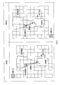
- the peripheral monitoring sensor 2 is installed in or around the front bumper, but the installation position of the peripheral monitoring sensor 2 is changed according to the height position of the small object to be detected. You may. Specifically, as shown in FIG. 11, when a small target located above is targeted for detection, the peripheral monitoring sensor 2 may be installed at a position as close to the road surface as possible. As a result, the rate of change ⁇ P of the detection probability P of the small target located above can be increased. Further, when a small target located below such as a falling object on the road surface is to be detected, the peripheral monitoring sensor 2 may be installed at a position as far as possible from the road surface, for example, around a rearview mirror. As a result, the rate of change ⁇ P of the detection probability P of the small target located below can be increased.
- the second embodiment is different from the first embodiment in that a plurality of peripheral monitoring sensors 2 having different installation heights are used.
- the obstacle detection device 1a of the present embodiment includes a plurality of two peripheral monitoring sensors 2a and 2b.
- the two peripheral monitoring sensors 2a and 2b are arranged so that their positions in the horizontal plane are the same and only the positions in the height direction are different.
- the grid map update process is the same as the grid map update process of the first embodiment described with reference to FIG. 3, except that the two peripheral monitoring sensors (hereinafter, simply sensors) 2a and 2b are executed individually. Is.
- the obstacle detection process is different from the obstacle detection process of the first embodiment described with reference to FIG. 6 in S220 and S230.
- the signal processing unit 10 calculates and registers the detection probability P of the target cell for each of the sensors 2a and 2b.
- the type determination process is different from the type determination process of the first embodiment described with reference to FIG. 7 in S310 and S350.
- the signal processing unit 10 makes a positive determination when the detection probability P of the target cell is P> TH1 for all the sensors 2a and 2b, and makes a negative determination when at least one of them is P ⁇ TH1.
- the signal processing unit 10 makes an affirmative determination when the detection probability P of the target cell is P> TH2 for at least one of the sensors 2a and 2b, and makes a negative determination when both are P ⁇ TH2.
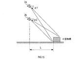
- the horizontal distance L between the sensors 2a and 2b and the small object is made constant, and the angle ⁇ (that is, the height position of the sensors 2a and 2b) when the small object is viewed from the front direction of the sensors 2a and 2b is set.
- FIG. 15 shows the horizontal distance L and the angles ⁇ 1 and ⁇ 2.
- ⁇ 1 is an angle with respect to the sensor 2a
- ⁇ 2 is an angle with respect to the sensor 2b.
- the angles ⁇ 1 and ⁇ 2 have a spread of angles in the small object viewed from the sensor, they have variations according to the spread.
- the target can be obtained from the detection probability P by referring to the conversion table. Can be estimated in the direction in which. Although the measured values are not linear, the estimation accuracy can be improved by combining the results of a plurality of sensors 2a and 2b having different height positions.
- the conversion table is stored in the memory 12 in advance. In addition, the conversion table corresponds to the corresponding information.
- the signal processing unit 10 obtains the angles ⁇ 1 and ⁇ 2 from the detection probabilities P1 and P2 calculated by the two sensors 2a and 2b for the target cell, respectively, using the conversion table.
- the signal processing unit 10 determines the position of the upper end of the small target, that is, the height of the small target, using the installation positions of the sensors 2a and 2b and the angles ⁇ 1 and ⁇ 2 obtained in S610. Outputs the judgment result and ends the process.
- the determination result may be represented by a specific numerical value, or may be represented by, for example, a height that the vehicle can overcome or a height that cannot be overcome.
- the installation position of the sensors 2a and 2b may be represented by the arrangement interval of both sensors 2a and 2b and the average height of both sensors 2a and 2b from the road surface. When the horizontal distance L is sufficiently large (for example, twice or more) with respect to the installation height of the sensors 2a and 2b, the difference in conversion characteristics depending on the arrangement interval of the sensors 2a and 2b can be ignored.
- the obstacle detection device 1a determines the height of a small target by using the detection probability P even when the signal strength is weak and the reception timing of the reflected wave and the distance to the target cannot be detected accurately. it can.
- the determination is performed using the threshold values TH1 to TH3 in the type determination process and the position determination process, but the present disclosure is not limited to this.
- the likelihood calculation may be used to make the determination.
- the distance change rate is used as the change rate ⁇ P of the detection probability in the position determination process, but the time change rate may also be used.
- the signal processing unit 10 and its method described in the present disclosure are provided by configuring a processor and memory programmed to perform one or more functions embodied by a computer program. It may be realized by a dedicated computer. Alternatively, the signal processing unit 10 and its method described in the present disclosure may be realized by a dedicated computer provided by configuring the processor with one or more dedicated hardware logic circuits. Alternatively, the signal processing unit 10 and its method described in the present disclosure include a processor and memory programmed to perform one or more functions and a processor composed of one or more hardware logic circuits. It may be realized by one or more dedicated computers configured by a combination. The computer program may also be stored on a computer-readable non-transitional tangible recording medium as an instruction executed by the computer. The method for realizing the functions of each unit included in the signal processing unit 10 does not necessarily include software, and all the functions may be realized by using one or a plurality of hardware.
- a plurality of functions possessed by one component in the above embodiment may be realized by a plurality of components, or one function possessed by one component may be realized by a plurality of components. .. Further, a plurality of functions possessed by the plurality of components may be realized by one component, or one function realized by the plurality of components may be realized by one component. Further, a part of the configuration of the above embodiment may be omitted. In addition, at least a part of the configuration of the above embodiment may be added or replaced with the configuration of the other above embodiment.
- a system having the obstacle detection device as a component, a program for operating a computer as the obstacle detection device, and a semiconductor memory in which this program is recorded can also be realized in various forms such as a non-transitional actual recording medium such as.
Landscapes
- Engineering & Computer Science (AREA)
- Radar, Positioning & Navigation (AREA)
- Remote Sensing (AREA)
- Physics & Mathematics (AREA)
- General Physics & Mathematics (AREA)
- Computer Networks & Wireless Communication (AREA)
- Electromagnetism (AREA)
- Acoustics & Sound (AREA)
- Radar Systems Or Details Thereof (AREA)
- Traffic Control Systems (AREA)
- Optical Radar Systems And Details Thereof (AREA)
Priority Applications (1)
| Application Number | Priority Date | Filing Date | Title |
|---|---|---|---|
| US17/455,638 US20220075074A1 (en) | 2019-05-20 | 2021-11-18 | Obstacle detection device and obstacle detection method |
Applications Claiming Priority (2)
| Application Number | Priority Date | Filing Date | Title |
|---|---|---|---|
| JP2019-094487 | 2019-05-20 | ||
| JP2019094487A JP7152355B2 (ja) | 2019-05-20 | 2019-05-20 | 障害物検出装置および障害物検出方法 |
Related Child Applications (1)
| Application Number | Title | Priority Date | Filing Date |
|---|---|---|---|
| US17/455,638 Continuation US20220075074A1 (en) | 2019-05-20 | 2021-11-18 | Obstacle detection device and obstacle detection method |
Publications (1)
| Publication Number | Publication Date |
|---|---|
| WO2020235396A1 true WO2020235396A1 (ja) | 2020-11-26 |
Family
ID=73454482
Family Applications (1)
| Application Number | Title | Priority Date | Filing Date |
|---|---|---|---|
| PCT/JP2020/019004 Ceased WO2020235396A1 (ja) | 2019-05-20 | 2020-05-12 | 障害物検出装置および障害物検出方法 |
Country Status (3)
| Country | Link |
|---|---|
| US (1) | US20220075074A1 (https=) |
| JP (1) | JP7152355B2 (https=) |
| WO (1) | WO2020235396A1 (https=) |
Families Citing this family (7)
| Publication number | Priority date | Publication date | Assignee | Title |
|---|---|---|---|---|
| US12061267B2 (en) * | 2018-12-12 | 2024-08-13 | Hitachi Astemo, Ltd. | External environment recognition device |
| JP7321401B2 (ja) * | 2021-03-02 | 2023-08-04 | 三菱電機株式会社 | レーダ信号処理装置 |
| JP7569014B2 (ja) * | 2021-05-10 | 2024-10-17 | トヨタ自動車株式会社 | 車両運転支援装置 |
| JP7420314B1 (ja) * | 2022-04-27 | 2024-01-23 | 三菱電機株式会社 | 移動体制御装置、移動体制御方法、及び移動体制御プログラム |
| TWI816387B (zh) * | 2022-05-05 | 2023-09-21 | 勝薪科技股份有限公司 | 語意距離地圖的建構方法及其相關移動裝置 |
| CN117471469A (zh) * | 2022-07-22 | 2024-01-30 | 长沙行深智能科技有限公司 | 障碍物检测方法、自移动设备及存储介质 |
| IT202400002539A1 (it) * | 2024-02-07 | 2025-08-07 | Ferrari Spa | Sistema di controllo per autoveicolo e metodo di controllo per autoveicolo |
Citations (7)
| Publication number | Priority date | Publication date | Assignee | Title |
|---|---|---|---|---|
| JP2008003662A (ja) * | 2006-06-20 | 2008-01-10 | Alpine Electronics Inc | 車両識別システム |
| JP2012047609A (ja) * | 2010-08-27 | 2012-03-08 | Honda Motor Co Ltd | 物体検知装置 |
| JP2012194039A (ja) * | 2011-03-16 | 2012-10-11 | Mitsubishi Electric Corp | 車載用レーダ装置 |
| WO2013076829A1 (ja) * | 2011-11-22 | 2013-05-30 | 株式会社日立製作所 | 自律移動システム |
| WO2014054239A1 (ja) * | 2012-10-04 | 2014-04-10 | 株式会社デンソー | 物体検知装置 |
| WO2016103464A1 (ja) * | 2014-12-26 | 2016-06-30 | 三菱電機株式会社 | 障害物検知装置及び障害物検知方法 |
| JP2017166971A (ja) * | 2016-03-16 | 2017-09-21 | 株式会社デンソー | 物体検出装置および物体検出プログラム |
Family Cites Families (8)
| Publication number | Priority date | Publication date | Assignee | Title |
|---|---|---|---|---|
| JP2007310741A (ja) * | 2006-05-19 | 2007-11-29 | Fuji Heavy Ind Ltd | 立体物認識装置 |
| DE102006058308A1 (de) * | 2006-12-11 | 2008-06-12 | Robert Bosch Gmbh | Verfahren und Vorrichtung zum Erfassen eines Hindernisses in einem Umgebungsbereich eines Kraftfahrzeugs und Kraftfahrzeug |
| JP4880712B2 (ja) * | 2009-02-27 | 2012-02-22 | 株式会社日本自動車部品総合研究所 | 障害物検出装置 |
| DE112009005292B8 (de) * | 2009-09-28 | 2015-04-02 | Toyota Jidosha Kabushiki Kaisha | Objekterfassungsvorrichtung |
| JP5206752B2 (ja) * | 2010-08-30 | 2013-06-12 | 株式会社デンソー | 走行環境認識装置 |
| JP6484000B2 (ja) * | 2014-10-22 | 2019-03-13 | 株式会社デンソー | 物体検知装置 |
| DE102017103275B4 (de) * | 2017-02-17 | 2024-08-14 | Valeo Schalter Und Sensoren Gmbh | Verfahren zum Erfassen eines Objekts in einem Umgebungsbereich eines Kraftfahrzeugs mithilfe eines Ultraschallsensors mit verbesserter Filterung von Bodenreflexionen, Steuergerät, Ultraschallsensorvorrichtung sowie Kraftfahrzeug |
| US10955540B2 (en) * | 2017-12-01 | 2021-03-23 | Aptiv Technologies Limited | Detection system |
-
2019
- 2019-05-20 JP JP2019094487A patent/JP7152355B2/ja active Active
-
2020
- 2020-05-12 WO PCT/JP2020/019004 patent/WO2020235396A1/ja not_active Ceased
-
2021
- 2021-11-18 US US17/455,638 patent/US20220075074A1/en active Pending
Patent Citations (7)
| Publication number | Priority date | Publication date | Assignee | Title |
|---|---|---|---|---|
| JP2008003662A (ja) * | 2006-06-20 | 2008-01-10 | Alpine Electronics Inc | 車両識別システム |
| JP2012047609A (ja) * | 2010-08-27 | 2012-03-08 | Honda Motor Co Ltd | 物体検知装置 |
| JP2012194039A (ja) * | 2011-03-16 | 2012-10-11 | Mitsubishi Electric Corp | 車載用レーダ装置 |
| WO2013076829A1 (ja) * | 2011-11-22 | 2013-05-30 | 株式会社日立製作所 | 自律移動システム |
| WO2014054239A1 (ja) * | 2012-10-04 | 2014-04-10 | 株式会社デンソー | 物体検知装置 |
| WO2016103464A1 (ja) * | 2014-12-26 | 2016-06-30 | 三菱電機株式会社 | 障害物検知装置及び障害物検知方法 |
| JP2017166971A (ja) * | 2016-03-16 | 2017-09-21 | 株式会社デンソー | 物体検出装置および物体検出プログラム |
Also Published As
| Publication number | Publication date |
|---|---|
| JP2020190429A (ja) | 2020-11-26 |
| US20220075074A1 (en) | 2022-03-10 |
| JP7152355B2 (ja) | 2022-10-12 |
Similar Documents
| Publication | Publication Date | Title |
|---|---|---|
| JP7152355B2 (ja) | 障害物検出装置および障害物検出方法 | |
| US9255988B2 (en) | Object fusion system of multiple radar imaging sensors | |
| CN108140323B (zh) | 用于机动车中的环境检测时改进的数据融合的方法和设备 | |
| US20230065727A1 (en) | Vehicle and vehicle control method | |
| US11328516B2 (en) | Apparatus and method for associating sensor data in vehicle | |
| JP6430777B2 (ja) | 物体検知装置 | |
| CN114137565B (zh) | 牵引车与挂车之间的角度检测方法、装置和电子设备 | |
| JP7155284B2 (ja) | 計測精度算出装置、自己位置推定装置、制御方法、プログラム及び記憶媒体 | |
| CN115151836A (zh) | 用于探测车辆周围环境中的移动对象的方法和机动车辆 | |
| CN113536850A (zh) | 基于77g毫米波雷达的目标物体大小测试方法和装置 | |
| JP7401273B2 (ja) | 移動体の制御装置及び方法 | |
| CN110888115A (zh) | 对雷达跟踪的潜在静止对象进行分类 | |
| JP2020020690A (ja) | 自車位置推定装置 | |
| JP7344744B2 (ja) | 路側端検出方法、及び、路側端検出装置 | |
| CN119156548A (zh) | 一种点云评估方法及装置 | |
| JP6555132B2 (ja) | 移動物体検出装置 | |
| JP2017016172A (ja) | 走路境界推定装置及び走路境界推定方法 | |
| CN116209920A (zh) | 借助激光雷达传感器的测量和计算设备来估计车辆自身运动的方法 | |
| CN114631038B (zh) | 信息生成装置、信息生成方法以及记录介质 | |
| JP7254664B2 (ja) | 演算装置 | |
| JPH05113482A (ja) | 車載用追突防止装置 | |
| KR101992115B1 (ko) | 차량용 레이다를 이용한 차선 추정 방법 및 시스템 | |
| JP2020160943A (ja) | 検出装置及び検出方法 | |
| US12198268B2 (en) | Information processing device | |
| CN116736243A (zh) | 使用多种假设的稳定的雷达跟踪速度初始化 |
Legal Events
| Date | Code | Title | Description |
|---|---|---|---|
| 121 | Ep: the epo has been informed by wipo that ep was designated in this application |
Ref document number: 20808753 Country of ref document: EP Kind code of ref document: A1 |
|
| NENP | Non-entry into the national phase |
Ref country code: DE |
|
| 122 | Ep: pct application non-entry in european phase |
Ref document number: 20808753 Country of ref document: EP Kind code of ref document: A1 |