WO2020235355A1 - 接続端子及びコネクタ - Google Patents
接続端子及びコネクタ Download PDFInfo
- Publication number
- WO2020235355A1 WO2020235355A1 PCT/JP2020/018647 JP2020018647W WO2020235355A1 WO 2020235355 A1 WO2020235355 A1 WO 2020235355A1 JP 2020018647 W JP2020018647 W JP 2020018647W WO 2020235355 A1 WO2020235355 A1 WO 2020235355A1
- Authority
- WO
- WIPO (PCT)
- Prior art keywords
- terminal
- connection
- tubular
- electric wire
- base
- Prior art date
- Legal status (The legal status is an assumption and is not a legal conclusion. Google has not performed a legal analysis and makes no representation as to the accuracy of the status listed.)
- Ceased
Links
Images






Classifications
-
- H—ELECTRICITY
- H01—ELECTRIC ELEMENTS
- H01R—ELECTRICALLY-CONDUCTIVE CONNECTIONS; STRUCTURAL ASSOCIATIONS OF A PLURALITY OF MUTUALLY-INSULATED ELECTRICAL CONNECTING ELEMENTS; COUPLING DEVICES; CURRENT COLLECTORS
- H01R13/00—Details of coupling devices of the kinds covered by groups H01R12/70 or H01R24/00 - H01R33/00
- H01R13/02—Contact members
- H01R13/10—Sockets for co-operation with pins or blades
- H01R13/11—Resilient sockets
- H01R13/111—Resilient sockets co-operating with pins having a circular transverse section
-
- H—ELECTRICITY
- H01—ELECTRIC ELEMENTS
- H01R—ELECTRICALLY-CONDUCTIVE CONNECTIONS; STRUCTURAL ASSOCIATIONS OF A PLURALITY OF MUTUALLY-INSULATED ELECTRICAL CONNECTING ELEMENTS; COUPLING DEVICES; CURRENT COLLECTORS
- H01R4/00—Electrically-conductive connections between two or more conductive members in direct contact, i.e. touching one another; Means for effecting or maintaining such contact; Electrically-conductive connections having two or more spaced connecting locations for conductors and using contact members penetrating insulation
- H01R4/28—Clamped connections, spring connections
- H01R4/30—Clamped connections, spring connections utilising a screw or nut clamping member
- H01R4/34—Conductive members located under head of screw
-
- H—ELECTRICITY
- H01—ELECTRIC ELEMENTS
- H01R—ELECTRICALLY-CONDUCTIVE CONNECTIONS; STRUCTURAL ASSOCIATIONS OF A PLURALITY OF MUTUALLY-INSULATED ELECTRICAL CONNECTING ELEMENTS; COUPLING DEVICES; CURRENT COLLECTORS
- H01R13/00—Details of coupling devices of the kinds covered by groups H01R12/70 or H01R24/00 - H01R33/00
- H01R13/46—Bases; Cases
- H01R13/502—Bases; Cases composed of different pieces
- H01R13/506—Bases; Cases composed of different pieces assembled by snap action of the parts
-
- H—ELECTRICITY
- H01—ELECTRIC ELEMENTS
- H01R—ELECTRICALLY-CONDUCTIVE CONNECTIONS; STRUCTURAL ASSOCIATIONS OF A PLURALITY OF MUTUALLY-INSULATED ELECTRICAL CONNECTING ELEMENTS; COUPLING DEVICES; CURRENT COLLECTORS
- H01R2201/00—Connectors or connections adapted for particular applications
- H01R2201/26—Connectors or connections adapted for particular applications for vehicles
Definitions
- This disclosure relates to connection terminals and connectors.
- vehicles such as plug-in hybrid vehicles and electric vehicles are provided with a charging connector for charging the mounted power storage device (see, for example, Patent Document 1).
- This type of vehicle is provided with various harnesses and various connectors including connection terminals for connecting the harnesses as members for electrically connecting the charging connector and the power storage device.
- the above connector has a problem that the manufacturing cost is high because the connection terminal is formed by cutting.
- An object of the present disclosure is to provide a connection terminal and a connector capable of suppressing an increase in manufacturing cost.
- connection terminal of the present disclosure is provided between a terminal connection portion electrically connected to the mating terminal, an electric wire connection portion electrically connected to the electric wire, and the terminal connection portion and the electric wire connection portion.
- the terminal connection portion has an intermediate portion, the terminal connection portion has a cylindrical shape, the terminal connection portion has a first slit extending over the entire length of the terminal connection portion in the axial direction, and the intermediate portion has a square cylinder.
- the intermediate portion has a second slit extending over the entire length of the intermediate portion in the axial direction.
- connection terminals and connectors of the present disclosure there is an effect that an increase in manufacturing cost can be suppressed.
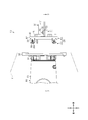
- FIG. 1 is a schematic perspective view showing a connector of one embodiment.
- FIG. 2 is a schematic side view showing a connector of one embodiment.
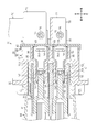
- FIG. 3 is a schematic cross-sectional view showing a connector of one embodiment.
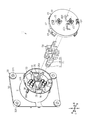
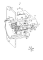
- FIG. 4 is a schematic exploded perspective view showing a vehicle-side connector of one embodiment.
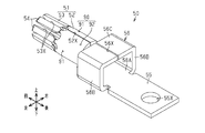
- FIG. 5 is a schematic perspective view showing a vehicle-side terminal of one embodiment.
- FIG. 6 is a schematic front view showing a vehicle-side terminal of one embodiment.
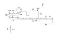
- FIG. 7 is a schematic cross-sectional view showing a vehicle-side terminal of one embodiment.
- FIG. 8 is a perspective sectional view showing a vehicle-side connector.
- FIG. 9 is a schematic perspective view showing the retainer of one embodiment.
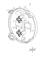
- FIG. 10 is a schematic rear view showing a vehicle-side connector of a modified example.
- FIG. 11 is a schematic perspective view showing a vehicle-side terminal of the modified example.
- FIG. 12 is a schematic perspective view showing the vehicle-side terminal of the modified example.
- FIG. 13 is a schematic cross-sectional view showing a part of the vehicle-side connector of the modified example.
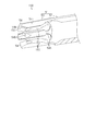
- FIG. 14 is a partially broken perspective view showing a part of the vehicle-side connector of the modified example.
- connection terminal of the present disclosure is between a terminal connection portion electrically connected to a mating terminal, an electric wire connection portion electrically connected to an electric wire, and the terminal connection portion and the electric wire connection portion.
- the terminal connecting portion has a provided intermediate portion, the terminal connecting portion has a cylindrical shape, the terminal connecting portion has a first slit extending over the entire length in the axial direction of the terminal connecting portion, and the intermediate portion has a first slit.
- the intermediate portion has a second slit extending over the entire length of the intermediate portion in the axial direction.
- the terminal connection portion and the intermediate portion are formed in a tubular shape having a hollow structure inside. Further, the terminal connection portion and the intermediate portion are formed with a first slit and a second slit extending over the entire length of the terminal connection portion and the intermediate portion in the axial direction, respectively. Therefore, the connection terminal including the terminal connection portion and the intermediate portion can be formed by press working. As a result, the connection terminal can be manufactured at a lower cost than the conventional connection terminal manufactured by cutting. As a result, an increase in the manufacturing cost of the connection terminal and the connector including the connection terminal can be suitably suppressed.
- the "cylindrical shape" in the present specification is not limited to one in which a peripheral wall is continuously formed over the entire circumference in the circumferential direction, but also one in which a slit extending in the axial direction is formed in a part in the circumferential direction or the radial direction. It also includes those having through holes formed through them.
- the terminal connection portion has a cylindrical base portion connected to the intermediate portion and a cylindrical tubular connection portion connected to the base portion, and the tubular connection portion has the tubular shape. It is preferable to have a plurality of elastic pieces provided at predetermined intervals along the circumferential direction of the connecting portion, and the plurality of elastic pieces have a cylindrical shape of the tubular connecting portion.
- connection terminal can be formed by press working, it is possible to suppress an increase in processing cost due to an increase in the number of elastic pieces as compared with the case where the connection terminal is formed by cutting. Therefore, the number of elastic pieces can be increased while suppressing the increase in manufacturing cost. As a result, the number of contacts with the mating terminal can be increased, so that the contact resistance between the mating terminal and the terminal connection portion can be lowered. As a result, heat generation when the connection terminal is energized can be suitably suppressed, so that a large current can flow through the connection terminal.
- Each elastic piece has a base end portion connected to the base portion, a tip end portion which is an end portion opposite to the base end portion in the axial direction of the tubular connection portion, and the base end portion. It has a contact portion provided between the tip portion and the tip portion, and the thickness dimension of the base end portion is preferably smaller than the thickness dimension of the contact portion.
- the thickness of the base end portion which is the fixed end of each elastic piece, is formed to be thinner than that of the contact portion, so that each elastic piece is easily elastically deformed.
- each elastic piece tends to bend in the radial direction of the tubular connection portion, so that each elastic piece can be suitably brought into contact with the mating terminal.
- the thickness dimension of the contact portion has a constant dimension over the entire length in the length direction of the contact portion along the axial direction of the tubular connection portion.
- the contact portion can be formed thicker than the base end portion over the entire length of the contact portion in the length direction.
- the cross-sectional area of the conductor at the contact portion can be increased, so that heat generation when the connection terminal is energized can be suitably suppressed.
- the thickness dimension of the tip portion decreases from the contact portion side toward the opening end of the tubular connection portion, and the inner diameter dimension of the tip portion of the tubular connection portion is the contact. It is preferable that the amount increases from the portion side toward the open end of the tubular connecting portion.
- the opening end portion of the tubular connecting portion is formed so that the opening diameter of the tubular connecting portion increases from the contact portion side toward the opening end of the tubular connecting portion.
- the tubular connection portion has a plurality of third slits extending from the opening end of the tubular connection portion over the entire length in the axial direction of the tubular connection portion, and the plurality of third slits are the cylinder. It is preferable that the shape connecting portions are provided at predetermined intervals along the circumferential direction, and a part of the third slits among the plurality of third slits constitutes the first slit.
- a plurality of third slits are formed so as to extend over the entire length in the axial direction of the tubular connection portion. Therefore, the water or mud that has entered the inside of the tubular connection portion can be suitably discharged to the outside of the tubular connection portion through the third slit.
- the base portion has a plurality of protrusions formed on the outer surface of the base portion, and the plurality of protrusions have two protrusions provided at different positions in the axial direction of the base portion. Each of the protrusions protrudes radially outward from the outer surface of the tubular connection portion.
- a protrusion is formed on the outer surface of the base portion so as to project radially outward from the outer surface of the tubular connection portion.
- the size of the planar shape of the intermediate portion viewed from the axial direction of the intermediate portion is larger than the size of the planar shape of the terminal connection portion viewed from the axial direction of the terminal connection portion. According to this configuration, since the conductor cross-sectional area in the intermediate portion can be increased, heat generation when the connection terminal is energized can be suitably suppressed.
- the electric wire connecting portion has a reinforcing portion protruding in a direction intersecting the length direction. According to this configuration, the strength of the electric wire connecting portion connected to the electric wire can be increased by providing the reinforcing portion. Further, since the cross-sectional area of the conductor at the electric wire connecting portion can be increased, heat generation when the connection terminal is energized can be suitably suppressed.
- the plurality of elastic pieces each have a plurality of inner peripheral surfaces surrounding the central axis of the tubular connection portion, and each of the plurality of inner peripheral surfaces has a recess. It is preferable that the recesses on the inner peripheral surface of the above are provided at the same positions in the axial direction of the tubular connecting portion. According to this configuration, the electrical connectivity between the connection terminal and the mating terminal can be improved by the recesses of the plurality of elastic pieces.
- Each elastic piece has a tip portion, and the recess is provided on the inner peripheral surface of each elastic piece at a position closer to the tip portion of each elastic piece than the base portion. Is preferable. According to this configuration, the electrical connectivity between the connection terminal and the mating terminal can be improved by locally processing the inner peripheral surface of the elastic piece.
- Each elastic piece has a contact portion between the base portion and the tip portion, and the inner peripheral surface of each elastic piece is a slope included in the tip portion of each elastic piece. It has an inner peripheral surface of the tip portion and an inner peripheral surface of the contact portion included in the contact portion, and the recess is the inner peripheral surface of the tip portion and the inner circumference of the contact portion on the inner peripheral surface of the contact portion of each elastic piece. It preferably extends adjacent to or across the boundary with the surface. According to this configuration, the electrical connectivity between the connection terminal and the mating terminal can be improved by locally processing the inner peripheral surface of the elastic piece.
- the connector of the present disclosure preferably has a connector according to any one of the above [1] to [13] and a connector housing for holding the connection terminal.
- the connector housing is attached to a vehicle, and the connector housing is fitted with a charging connector. According to this configuration, an increase in manufacturing cost in the connector to which the charging connector is fitted can be suitably suppressed.
- connection terminals and connectors of the present disclosure will be described below with reference to the drawings.
- a part of the structure may be exaggerated or simplified for convenience of explanation.
- the dimensional ratio of each part may differ in each drawing.
- Parallel, “orthogonal” and “horizontal” in the present specification are not only strictly parallel, orthogonal and horizontal, but also generally parallel, orthogonal and horizontal within the range in which the action and effect in the present embodiment are exhibited. included.
- opposite means that faces or members are in front of each other, not only when they are completely in front of each other, but also when they are partially in front of each other. Including the case. It should be noted that the present invention is not limited to these examples, and is indicated by the scope of claims, and is intended to include all modifications within the meaning and scope equivalent to the scope of claims.
- the vehicle-side connector 10 shown in FIG. 1 is for charging a power storage device (not shown) mounted on a vehicle V (see FIG. 2) such as an electric vehicle or a plug-in hybrid vehicle.
- the vehicle-side connector 10 is, for example, a connector for quick charging in which a large current of about 200 A to 400 A flows.
- the vehicle-side connector 10 is fixed to the vehicle V by a fastening member (not shown) such as a bolt.
- the vehicle-side connector 10 is connected to a power storage device (not shown) via an electric wire 70.
- a charger-side connector 80 (charging connector) is connected to the vehicle-side connector 10 as a mating-side connector.
- the charger-side connector 80 is connected to the vehicle-side connector 10 from the left side in the drawing.
- the left-right direction in FIGS. 2 and 3 is the insertion / removal direction of the charger-side connector 80.
- the horizontal direction in FIGS. 2 and 3 is referred to as a front-rear direction
- the vertical direction in FIG. 2 is referred to as a vertical direction
- the vertical direction in FIG. 3 is referred to as a horizontal direction.
- the left side of FIG. 2 is the front
- the right side of FIG. 2 is the rear
- the upper side of FIG. 2 is the upper side
- the lower side of FIG. 2 is the lower side
- the upper side of FIG. 3 is the right side
- the vehicle-side connector 10 has a connector housing 20 and one or more (two in this embodiment) vehicle-side terminals 50.
- the connector housing 20 has a housing body 30 and a retainer 40.
- the housing body 30 is made of an insulating synthetic resin.
- the housing body 30 includes a fitting portion 31, a flange portion 32, a tubular portion 33, one or more (two in this embodiment) terminal accommodating portions 34, and one or more (in this embodiment). It has two) terminal holding portions 35.
- the fitting portion 31 is formed in a tubular shape, for example.
- the charger side connector 80 is inserted into the fitting portion 31.
- the charger-side connector 80 has a connector housing 81 and a charger-side terminal 82 (counterpart terminal) held in the connector housing 81.
- the tip end portion (here, the rear end portion) of the connector housing 81 is fitted inside the fitting portion 31.
- the fitting portion 31 is formed in a tubular shape, for example, with one end (here, the rear end) closed.
- the fitting portion 31 of the present embodiment is formed in a cylindrical shape with an open front end.
- the fitting portion 31 has, for example, a cylindrical hood portion 31A and a back wall portion 31B that closes the rear end of the hood portion 31A.
- the flange portion 32 is formed so as to project from the outer peripheral surface of the hood portion 31A toward the outer side in the radial direction of the hood portion 31A.
- the flange portion 32 is formed, for example, so as to project radially outward over the entire circumferential direction of the hood portion 31A.
- the flange portion 32 of this embodiment is formed in the shape of a rectangular plate.
- the flange portion 32 has a plurality of mounting holes 32X that penetrate the flange portion 32 in the plate thickness direction (here, the front-rear direction).
- a fastening member such as a bolt is inserted into each mounting hole 32X.
- the vehicle-side connector 10 is fixed to the vehicle V (see FIG. 2) by these fastening members.
- the tubular portion 33 extends rearward from the back wall portion 31B.
- the tubular portion 33 of the present embodiment is formed in a cylindrical shape.
- the outer peripheral surface of the tubular portion 33 is formed continuously with, for example, the outer peripheral surface of the hood portion 31A formed behind the flange portion 32.
- the inner diameter of the tubular portion 33 is formed to be larger than the inner diameter of the fitting portion 31, for example.
- Each terminal accommodating portion 34 extends forward from the back wall portion 31B. Each terminal accommodating portion 34 is formed so as to be surrounded by the hood portion 31A. Each terminal accommodating portion 34 is formed in a tubular shape, for example. Each terminal accommodating portion 34 of the present embodiment is formed in a cylindrical shape. The two terminal accommodating portions 34 are provided side by side in the left-right direction of the vehicle-side connector 10, for example.
- Each terminal holding portion 35 extends toward the rear of the back wall portion 31B.
- Each terminal holding portion 35 is formed in a tubular shape having a hollow structure inside.
- Each terminal holding portion 35 has a peripheral wall 36 surrounding the vehicle-side terminal 50. The peripheral wall 36 is formed so as to extend in the front-rear direction.
- each terminal holding portion 35 of the present embodiment is formed in a square tubular shape.
- Each terminal holding portion 35 has a rectangular shape as viewed from the axial direction (here, the front-rear direction) of the terminal holding portion 35. That is, each terminal holding portion 35 has four peripheral walls 36.
- Each peripheral wall 36 is formed in a plate shape. In each terminal holding portion 35, four peripheral walls 36 are continuously and integrally formed.
- Each terminal holding portion 35 has a slit 35X extending in the axial direction of the terminal holding portion 35.
- the slit 35X is formed so as to extend over the entire length of the terminal holding portion 35 in the axial direction, for example.
- the slit 35X is formed in, for example, the peripheral wall 36 provided on the lower side of the four peripheral walls 36.
- each terminal holding portion 35 communicates with, for example, the internal space of each terminal accommodating portion 34.
- the internal space of each terminal holding portion 35 is formed wider than, for example, the internal space of the terminal accommodating portion 34.
- the internal space of each terminal holding portion 35 is formed to be one size larger than that of the terminal accommodating portion 34.
- a part of the rear surface of the back wall portion 31B is exposed on each terminal holding portion 35.
- Vehicle-side terminals 50 are inserted into the terminal accommodating portion 34 and the terminal holding portion 35. That is, each terminal accommodating portion 34 and each terminal holding portion 35 form a terminal accommodating cylinder for accommodating the vehicle-side terminal 50.
- the housing body 30 has a plurality of signal terminal holding portions 37.
- Each signal terminal holding portion 37 accommodates a signal terminal (not shown).
- the signal terminal is used, for example, for communication with a charging device.
- a signal line is connected to the signal terminal.
- each vehicle side terminal 50 has, for example, a terminal connection portion 51 electrically connected to a charger side terminal 82 (see FIG. 3) which is a mating terminal, and an electric wire 70 (FIG. 3). 3) and an electric wire connecting portion 55 that is electrically connected.
- Each vehicle-side terminal 50 has an intermediate portion 56 provided between the terminal connecting portion 51 and the electric wire connecting portion 55.
- Each vehicle-side terminal 50 is, for example, a single component in which a terminal connecting portion 51, an intermediate portion 56, and an electric wire connecting portion 55 are connected in the front-rear direction and integrally formed.
- each vehicle side terminal 50 for example, a metal material such as copper, copper alloy, aluminum, aluminum alloy, or stainless steel can be used.
- Each vehicle-side terminal 50 may be subjected to surface treatment such as silver plating, tin plating, or aluminum plating, depending on the type of the constituent metal and the usage environment.
- Each vehicle-side terminal 50 can be formed by pressing a metal plate having excellent conductivity.
- the direction in which the terminal connection portion 51, the intermediate portion 56, and the electric wire connection portion 55 are aligned is referred to as a “length direction”.
- the length direction of the vehicle side terminal 50 coincides with the front-rear direction.
- the terminal connecting portion 51 is provided, for example, at the front end of the vehicle-side terminal 50.
- the terminal connection portion 51 is, for example, a female terminal.
- the terminal connecting portion 51 has a base portion 52 and a tubular connecting portion 53 provided in front of the base portion 52.
- the terminal connecting portion 51 is formed integrally with the base portion 52 and the tubular connecting portion 53 connected in the length direction.
- the base 52 is formed in a tubular shape having a hollow structure inside.
- the base 52 is formed in a cylindrical shape.
- the base portion 52 has a slit 52X extending over the entire length in the axial direction in which the central axis of the base portion 52 extends.
- the base 52 is housed in, for example, the terminal housing 34.
- the outer diameter of the base 52 is set to be slightly smaller than the inner diameter of the terminal accommodating portion 34, for example.
- at least a part of the outer peripheral surface of the base 52 is in contact with the inner peripheral surface of the terminal housing 34.
- the contact between the outer peripheral surface of the base portion 52 and the inner peripheral surface of the terminal accommodating portion 34 may be in any form of surface contact, line contact, or point contact.
- the tubular connection portion 53 is formed in a tubular shape having a hollow structure inside.
- the tubular connecting portion 53 is formed in a cylindrical shape.
- the charger-side terminal 82 of the charger-side connector 80 is inserted into the tubular connection portion 53.
- the charger side terminal 82 of this embodiment is a male terminal.
- the tubular connecting portion 53 has, for example, a plurality of elastic pieces 54 provided at predetermined intervals along the circumferential direction of the tubular connecting portion 53.
- the tubular connecting portion 53 is formed, for example, so that a plurality of elastic pieces 54 form a cylindrical shape as a whole.
- the inner peripheral surface or the radial inward surface of the plurality of elastic pieces 54 corresponds to the inner contour or inner surface of the tubular connecting portion 53.
- the outer peripheral surface or the radial inward surface of the plurality of elastic pieces 54 corresponds to the outer contour or outer surface of the tubular connecting portion 53.
- tubular connecting portion 53 of the present embodiment eight elastic pieces 54 are provided at predetermined intervals along the circumferential direction of the base portion 52. In the tubular connecting portion 53 of the present embodiment, eight elastic pieces 54 are provided at equal intervals along the circumferential direction of the base portion 52.
- the tubular connecting portion 53 is provided with slits 53X extending over the entire length in the axial direction in which the central axis of the tubular connecting portion 53 extends, at predetermined intervals along the circumferential direction of the tubular connecting portion 53.
- a part of the plurality of slits 53X is formed continuously with, for example, the slits 52X of the base 52. That is, a part of the slit 53X is formed so as to communicate with the slit 52X of the base 52.
- the slit 52X is formed so that the dimension (that is, the width dimension) along the circumferential direction of the base 52 is narrower than that of the slit 53X.
- Each slit 53X is formed so that the width dimension is constant over the entire length in the length direction, for example.
- each elastic piece 54 has a base end portion 54A (here, a rear end portion) connected to the base portion 52 and a tip end portion 54B located on the opposite side in the length direction from the base end portion 54A. (Here, the front end portion) and the contact portion 54C located between the base end portion 54A and the tip end portion 54B.
- Each elastic piece 54 is formed in a cantilever shape with a tip portion 54B as a free end and a base end portion 54A as a fixed end.
- Each elastic piece 54 has a spring property.
- Each elastic piece 54 is configured to be able to bend in the radial direction due to elastic deformation, for example.
- the base end portion 54A is formed, for example, to have a dimension (that is, a thickness dimension) along the radial direction of the tubular connecting portion 53 smaller than that of the contact portion 54C.
- the base end portion 54A is formed to have a smaller thickness than the base portion 52, for example.
- the thickness dimension of the contact portion 54C is formed to be the same as the thickness dimension of the base portion 52, for example.
- the thickness dimension of the contact portion 54C is formed so as to be constant over the entire length of the contact portion 54C in the length direction, for example.
- the tip portion 54B is formed to have a smaller thickness than the contact portion 54C, for example.
- the thickness dimension of the tip portion 54B is formed so as to decrease from the contact portion 54C side toward the opening end of the tubular connecting portion 53.
- the inner surface of the tip portion 54B is formed on a slope.
- the outer diameter dimension of the tubular connecting portion 53 is set to be smaller than the inner diameter dimension of the terminal accommodating portion 34, for example.
- the inner diameter of the tubular connection 53 is set to be slightly smaller than the outer diameter of the charger side terminal 82.
- the tubular connecting portion 53 is formed so that, for example, the inner diameter dimension decreases from the base 52 side toward the opening end of the tubular connecting portion 53.
- the tubular connecting portion 53 is formed at the tip portion 54B so that the inner diameter dimension increases from the contact portion 54C side toward the opening end of the tubular connecting portion 53. That is, the tip portion of the tubular connection portion 53 is formed in a shape that invites the charger side terminal 82 to the back side in the insertion direction of the tubular connection portion 53.
- a plurality of elastic pieces 54 are formed on the outer peripheral surface of the charger side terminal 82. Contact.
- the tubular connection portion 53 (terminal connection portion 51) and the charger side terminal 82 are electrically connected.
- the base portion 52 and the tubular connecting portion 53 (that is, the terminal connecting portion 51) described above are housed in the terminal accommodating portion 34.
- the electric wire connecting portion 55 is provided, for example, at the rear end of the vehicle-side terminal 50.
- the electric wire connecting portion 55 is electrically connected to the end portion of the electric wire 70.
- the electric wire 70 of the present embodiment has a bus bar 71 made of a metal material having excellent conductivity.
- the bus bar 71 is formed in a flat plate shape, for example.
- the bus bar 71 has, for example, a through hole 71X penetrating in the plate thickness direction (here, the vertical direction).
- a metal material such as copper-based or aluminum-based can be used.
- the electric wire connection portion 55 is formed in a flat plate shape.
- the electric wire connecting portion 55 has, for example, a through hole 55X penetrating in the plate thickness direction (here, the vertical direction).
- the electric wire connecting portion 55 is connected to the bus bar 71 by, for example, bolt fastening, ultrasonic welding, crimping, or the like.
- the bus bar 71 is provided on the upper surface of the wire connecting portion 55 so that the through hole 55X of the electric wire connecting portion 55 and the through hole 71X of the bus bar 71 overlap in the vertical direction. Then, the electric wire connecting portion 55 and the bus bar 71 are connected by fastening the nut 76 to the shaft portion of the bolt 75 inserted into the through hole 55X and the through hole 71X. As a result, the electric wire connecting portion 55 and the bus bar 71 are electrically connected.
- reinforcing portions 57 projecting in a direction intersecting the length direction of the vehicle side terminal 50 are formed at both ends of the electric wire connecting portion 55 in the left-right direction.
- the reinforcing portion 57 of the present embodiment is formed so as to project downward from both ends in the left-right direction of the electric wire connecting portion 55.
- Each reinforcing portion 57 is formed so as to extend over the entire length in the length direction of the electric wire connecting portion 55, for example.
- the intermediate portion 56 is provided between, for example, the terminal connecting portion 51 and the electric wire connecting portion 55.
- the intermediate portion 56 is formed in a square tubular shape having a hollow structure inside.
- the intermediate portion 56 is formed so that the planar shape seen from the axial direction in which the central axis of the intermediate portion 56 extends is rectangular.
- the intermediate portion 56 of the present embodiment includes a bottom wall 56A formed continuously and integrally with the electric wire connecting portion 55, and a pair of side walls 56B formed so as to project upward from both left and right ends of the bottom wall 56A. It has an opposing wall 56C that is integrally formed with the side wall 56B and is formed so as to face the bottom wall 56A.
- the intermediate portion 56 has a slit 56X extending over the entire length in the axial direction of the intermediate portion 56.
- the slit 56X is formed in, for example, the facing wall 56C.
- the slit 56X of the present embodiment is formed at the center of the facing wall 56C in the left-right direction.
- the intermediate portion 56 is held by, for example, the terminal holding portion 35.
- the intermediate portion 56 is formed in a size that can be accommodated in the internal space of the terminal holding portion 35, for example.
- the outer surface of the intermediate portion 56 is formed in a shape corresponding to, for example, the inner surface of the terminal holding portion 35.
- the terminal holding portion 35 is formed so as to surround the outer periphery of the intermediate portion 56.
- the outer dimension of the intermediate portion 56 is formed to be larger than the inner diameter of the terminal accommodating portion 34, for example.
- the front surface of the intermediate portion 56 is locked to, for example, the rear surface of the back wall portion 31B exposed from the terminal holding portion 35.
- at least a part of the outer surface of the intermediate portion 56 is in contact with the inner surface of the terminal holding portion 35.
- the contact between the outer surface of the intermediate portion 56 and the inner surface of the terminal holding portion 35 may be in any form of surface contact, line contact, or point contact.
- the vehicle-side terminal 50 has a through hole 58 formed between the terminal connecting portion 51 and the electric wire connecting portion 55.
- the through hole 58 is formed in, for example, the bottom wall 56A of the intermediate portion 56.
- the through hole 58 is formed so as to discharge a liquid such as water flowing from the terminal connecting portion 51 side in a direction different from the direction toward the electric wire connecting portion 55.
- the through hole 58 is formed so as to penetrate the bottom wall 56A in the plate thickness direction (here, the vertical direction), for example.
- the through hole 58 is formed so as to extend in the left-right direction, for example.
- the through hole 58 is formed at a position overlapping the slit 35X of the terminal holding portion 35 in the vertical direction in a state where the vehicle side terminal 50 is accommodated in the terminal accommodating portion 34 and the terminal holding portion 35. There is.
- These through holes 58 and slits 35X function as drain holes for allowing liquid such as water that has entered from the terminal connection portion 51 side to escape to a portion other than the electric wire connection portion 55 (here, downward).
- a connecting portion 59 having a size smaller in the left-right direction than the bottom wall 56A of the electric wire connecting portion 55 and the intermediate portion 56 is formed between the electric wire connecting portion 55 and the intermediate portion 56. ..
- groove portions 59X recessed in the central portion in the left-right direction are formed at both ends of the connecting portion 59 in the left-right direction.
- the plate thickness (that is, the thickness dimension) is formed to be constant as a whole, and a part of the base end portion 54A and the tip end portion 54B. Is formed so that the thickness dimension is partially reduced in.
- the thickness of most of the vehicle-side terminal 50, specifically, the thickness of the vehicle-side terminal 50 in the portion where the thickness dimension is not set to be small can be, for example, about 2 to 3 mm.
- the retainer 40 is attached to the rear end of the tubular portion 33 of the housing body 30.
- the retainer 40 prevents the vehicle side terminal 50 from coming off.
- the retainer 40 is made of, for example, a synthetic resin.
- a synthetic resin such as polyolefin, polyamide, polyester, or ABS resin can be used.
- the retainer 40 has a base 41, a peripheral wall 42, and a terminal holding portion 43.
- the base 41 is formed, for example, in the shape of a circular plate.
- the peripheral wall 42 is formed so as to project forward from the peripheral edge of the base 41, for example.
- the peripheral wall 42 is formed, for example, over the entire circumference of the peripheral portion of the base 41 in the circumferential direction.
- the peripheral wall 42 is arranged on the outside of the tubular portion 33 of the housing body 30, for example. That is, the peripheral wall 42 is fitted to the outside of the tubular portion 33 of the housing body 30.
- a plurality of locking portions 38 are formed on the outer peripheral surface of the tubular portion 33.
- the plurality of locking portions 38 are provided at predetermined intervals in the circumferential direction of the tubular portion 33.
- Each locking portion 38 is formed with a locking claw 38A that projects outward in the radial direction of the tubular portion 33.
- a plurality of lock frame portions 44 are formed on the peripheral wall 42 to which the locking claws 38A of the locking portions 38 are locked.
- Each lock frame portion 44 is provided at a position corresponding to the locking portion 38. That is, the plurality of lock frame portions 44 are provided at predetermined intervals in the circumferential direction of the peripheral wall 42.
- Each lock frame portion 44 has, for example, a substantially U-shaped frame shape, and has an engaging hole 44X in which the locking claw 38A can be engaged.
- Each lock frame portion 44 is formed in a cantilever shape having a base end portion (that is, an end portion connected to the base portion 41) as a fixed end and a tip end portion opposite to the base end portion as a free end. ..
- Each lock frame portion 44 is configured to be able to bend in the radial direction due to elastic deformation, for example.
- the retainer 40 is attached to the rear end of the tubular portion 33, for example, by engaging the locking claw 38A with the engaging hole 44X of each lock frame portion 44.
- the terminal holding portion 43 is formed, for example, protruding forward from the base portion 41.
- the terminal holding portion 43 is provided at a position corresponding to the terminal holding portion 35 of the housing main body 30.
- the terminal holding portion 43 of the present embodiment has a U-shaped planar shape when viewed from the front-rear direction.
- the terminal holding portion 43 is formed, for example, in a U shape with the lower side open.
- the terminal holding portion 43 is formed at a position corresponding to the side wall 56B and the facing wall 56C of the intermediate portion 56 of the vehicle side terminal 50.
- the tip of the terminal holding portion 43 is in contact with the rear surface of the side wall 56B and the rear surface of the facing wall 56C. With this retainer 40, the vehicle side terminal 50 can be prevented from coming off from the rear.
- the retainer 40 has, for example, a through hole 40X into which the electric wire connecting portion 55 and the reinforcing portion 57 of the vehicle side terminal 50 are inserted.
- the through hole 40X is formed so as to penetrate the base 41 in the front-rear direction.
- the through hole 40X is formed in a shape corresponding to the electric wire connecting portion 55 and the reinforcing portion 57.
- the through hole 40X of the present embodiment has a U-shaped planar shape when viewed from the front-rear direction.
- the through hole 40X is formed below the terminal holding portion 43.
- the retainer 40 has, for example, a drain hole 40Y provided at the lower end of the base 41.
- the drainage hole 40Y is formed so as to penetrate the base 41 in the front-rear direction.
- the drain hole 40Y is for discharging a liquid such as water flowing through the through hole 58 of the vehicle side terminal 50 and the slit 35X of the terminal holding portion 35 to the outside of the vehicle side connector 10. It is a hole.
- the retainer 40 has, for example, a plurality of signal line holding units 45.
- a signal line connected to a signal terminal held by the signal terminal holding portion 37 of the housing main body 30 is inserted into the signal line holding portion 45.
- the signal terminal is prevented from coming off from the rear by the signal line holding portion 45.
- the vehicle-side terminal 50 includes a terminal connection portion 51 that is electrically connected to the charger-side terminal 82 that is a mating terminal, an electric wire connection portion 55 that is electrically connected to the electric wire 70, and a terminal connection portion 51. It has an intermediate portion 56 provided between the wire connecting portion 55 and the electric wire connecting portion 55.
- the terminal connection portion 51 is formed in a cylindrical shape.
- the terminal connection portion 51 has slits 52X and 53X extending over the entire length of the terminal connection portion 51 in the axial direction.
- the intermediate portion 56 is formed in a square tubular shape.
- the intermediate portion 56 has a slit 56X extending over the entire axial length of the intermediate portion 56.
- the terminal connection portion 51 and the intermediate portion 56 are formed in a tubular shape having a hollow structure inside. Further, the terminal connection portion 51 and the intermediate portion 56 are formed with slits 52X, 53X, 56X extending over the entire length of the terminal connection portion 51 and the intermediate portion 56 in the axial direction. Therefore, the vehicle-side terminal 50 including the terminal connection portion 51 and the intermediate portion 56 can be formed by press working. As a result, the vehicle-side terminal 50 can be manufactured at a lower cost than the conventional connection terminal manufactured by cutting. As a result, an increase in manufacturing cost of the vehicle-side terminal 50 and the vehicle-side connector 10 can be suitably suppressed.
- the terminal connecting portion 51 has a cylindrical base portion 52 connected to the intermediate portion 56 and a cylindrical tubular connecting portion 53 connected to the base portion 52.
- the tubular connecting portion 53 has a plurality of elastic pieces 54 provided at predetermined intervals along the circumferential direction of the tubular connecting portion 53, and the plurality of elastic pieces 54 are cylindrical in the tubular connecting portion 53. It is formed to form a contour.
- the plurality of elastic pieces 54 can be brought into contact with the charger side terminal 82, which is the other terminal, at multiple points. Therefore, a large number of contacts with the charger side terminal 82 can be secured, and the contact resistance between the charger side terminal 82 and the terminal connection portion 51 can be reduced. Further, since the vehicle-side terminal 50 can be formed by press working, it is possible to suppress an increase in processing cost due to an increase in the number of elastic pieces 54 as compared with the case where the connection terminal is formed by cutting. Therefore, the number of elastic pieces 54 can be increased while suppressing the increase in manufacturing cost. As a result, the number of contacts with the charger side terminal 82 can be increased, so that the contact resistance between the charger side terminal 82 and the terminal connection portion 51 can be suitably reduced.
- Each elastic piece 54 has a base end portion 54A connected to the base portion 52, a tip end portion 54B which is an end portion opposite to the base end portion 54A in the axial direction of the tubular connecting portion 53, and a base end. It has a contact portion 54C provided between the portion 54A and the tip portion 54B.
- the thickness dimension of the base end portion 54A is formed to be smaller than the thickness dimension of the contact portion 54C.
- the thickness of the base end portion 54A which is the fixed end of each elastic piece 54, is formed to be thinner than that of the contact portion 54C, so that each elastic piece 54 is easily elastically deformed.
- each elastic piece 54 tends to bend in the radial direction of the tubular connecting portion 53, so that each elastic piece 54 can be suitably brought into contact with the outer surface of the charger side terminal 82.
- the thickness dimension of the contact portion 54C is formed to be a constant dimension over the entire length direction of the contact portion 54C along the axial direction of the tubular connecting portion 53. According to this configuration, the contact portion 54C can be formed thicker than the base end portion 54A over the entire length of the contact portion 54C in the length direction. As a result, the conductor cross-sectional area of the contact portion 54C and the tubular connecting portion 53 can be increased, so that heat generation when the vehicle side terminal 50 is energized can be suitably suppressed.
- the thickness dimension of the tip portion 54B is formed so as to decrease from the contact portion 54C side toward the opening end side of the tubular connecting portion 53.
- the tubular connecting portion 53 is formed at the tip portion 54B so that the inner diameter dimension increases from the contact portion 54C side toward the opening end of the tubular connecting portion 53.
- the opening end portion of the tubular connecting portion 53 is formed so that the opening diameter of the tubular connecting portion 53 increases from the contact portion 54C side toward the opening end of the tubular connecting portion 53. ..
- the tubular connection portion 53 has a plurality of slits 53X extending from the opening end of the tubular connection portion 53 over the entire length in the axial direction of the tubular connection portion 53.
- the plurality of slits 53X are provided at predetermined intervals along the circumferential direction of the tubular connecting portion 53. A part of the slits 53X out of the plurality of slits 53X is communicated with the slit 52X of the base 52.
- a plurality of slits 53X are formed so as to extend over the entire length in the axial direction of the tubular connecting portion 53. Therefore, the water or mud that has entered the inside of the tubular connection portion 53 can be suitably discharged to the outside of the tubular connection portion 53 through the slit 53X.
- the size of the planar shape of the intermediate portion 56 viewed from the axial direction of the intermediate portion 56 is formed to be larger than the size of the planar shape of the terminal connecting portion 51 viewed from the axial direction of the terminal connecting portion 51. According to this configuration, since the conductor cross-sectional area in the intermediate portion 56 can be increased, heat generation when the vehicle side terminal 50 is energized can be suitably suppressed.
- the vehicle-side terminal 50 has a through hole 58 formed between the electric wire connecting portion 55 and the terminal connecting portion 51.
- the through hole 58 is formed so as to discharge the liquid in a direction different from the direction toward the electric wire connecting portion 55 (downward in the present embodiment).
- a liquid such as water may flow from the terminal connection portion 51 side toward the wire connection portion 55 side by the through hole 58 formed between the electric wire connection portion 55 and the terminal connection portion 51.
- the electric wire connecting portion 55 is formed with a reinforcing portion 57 protruding in a direction intersecting the length direction in which the terminal connecting portion 51, the intermediate portion 56, and the electric wire connecting portion 55 are lined up. According to this configuration, the strength of the electric wire connecting portion 55 connected to the electric wire 70 can be increased by providing the reinforcing portion 57. Further, since the conductor cross-sectional area at the electric wire connecting portion 55 can be increased, heat generation when the vehicle side terminal 50 is energized can be suitably suppressed.
- the structure of the connector housing 20 in the above embodiment is not particularly limited. That is, the connector housing 20 is not particularly limited as long as it has a structure capable of holding the vehicle-side terminal 50.
- the terminal holding portion 35 may be changed to a cylindrical terminal holding portion 35A.
- the terminal holding portion 35A is formed so as to surround the intermediate portion 56 having a square tubular shape.
- the terminal holding portion 35A has a slit 35Y extending over the entire length of the terminal holding portion 35A in the axial direction.
- the slit 35Y is provided, for example, at the lower end of the terminal holding portion 35 in the circumferential direction.
- the inner diameter of the terminal holding portion 35A is set to a size that allows the rotation of the intermediate portion 56 with the central axis of the intermediate portion 56 as the rotation axis inside the terminal holding portion 35A, for example.
- the inner diameter of the terminal holding portion 35A is set to, for example, a size that can regulate the rotation of the intermediate portion 56 with the central axis of the intermediate portion 56 as the rotation axis within a predetermined range. For example, the rotation of the intermediate portion 56 with the central axis of the intermediate portion 56 as the rotation axis is restricted by contacting a part of the outer surface of the intermediate portion 56 with the inner surface of the terminal holding portion 35A.
- the slit 35X is formed so as to extend over the entire length in the axial direction of the terminal holding portion 35A, but the present invention is not limited to this.
- the slit 35X may be formed only in a part of the terminal holding portion 35A in the axial direction.
- the slit 35X may be formed only at a position in the axial direction of the terminal holding portion 35A that overlaps the through hole 58 of the vehicle side terminal 50 in the vertical direction.
- the retainer 40 in the above embodiment may be omitted.
- a plurality of protrusions 90 protruding outward in the radial direction of the base 52 may be formed on the outer surface of the base 52 of the vehicle side terminal 50.
- Each protrusion 90 is formed so as to project radially outward from the outer surface of each elastic piece 54 of the tubular connecting portion 53.
- the plurality of protrusions 90 are provided at different positions in the axial direction of the base 52.
- the plurality of protrusions 90 include a plurality of (here, three) protrusions 91 provided on the side close to the tubular connection portion 53, and a plurality (here, three) protrusions 91 provided on the side close to the intermediate portion 56. It has three) protrusions 92.
- the protrusion 91 and the protrusion 92 are provided at different positions in the circumferential direction of the base 52, for example.
- the plurality of protrusions 91 are provided at positions on the same circumference of the base 52 at predetermined intervals along the circumferential direction, for example.
- the plurality of protrusions 91 are provided at positions separated by 2 ⁇ / 3 [rad] along the circumferential direction of the base 52, for example.
- the plurality of protrusions 92 are provided, for example, on the same circumference of the base 52 at predetermined intervals along the circumferential direction.
- the plurality of protrusions 92 are provided, for example, at positions separated by 2 ⁇ / 3 [rad] along the circumferential direction of the base portion 52.
- each protrusion 90 is formed so as to bulge from the outer surface of the base 52 toward the outside in the radial direction of the base 52, for example.
- Each protrusion 90 is formed continuously and integrally with the base 52, for example.
- a recess 90X recessed toward the protrusion 90 is formed at a position corresponding to each protrusion 90 on the inner surface of the base 52.
- the protrusion 90 and the recess 90X are formed so as to overlap each other in the radial direction of the base 52.
- a protrusion 90 is provided on the outer surface of the base portion 52 so as to project radially outward from the outer surface of the tubular connecting portion 53. Therefore, for example, when the vehicle-side terminal 50 is tilted in the terminal accommodating portion 34, the protrusion 90 is placed on the terminal accommodating portion 34 before the outer surface of the tubular connecting portion 53 comes into contact with the inner surface of the terminal accommodating portion 34. Can be brought into contact with the inner surface. As a result, even when the vehicle-side terminal 50 is tilted in the terminal accommodating portion 34, it is possible to preferably prevent the vehicle-side terminal 50 from coming into contact with the inner surface of the terminal accommodating portion 34. Therefore, it is possible to preferably suppress an increase in the insertion force when the charger side terminal 82 is inserted into the tubular connection portion 53.
- the number and formation positions of the protrusions 90 are not particularly limited.
- the structure of the vehicle-side terminal 50 in the above embodiment is not particularly limited. That is, the vehicle side terminal 50 is not particularly limited in other structures as long as it has a cylindrical terminal connecting portion 51, an electric wire connecting portion 55, and an intermediate portion 56 forming a square cylinder.
- the number of elastic pieces 54 in the tubular connecting portion 53 is not particularly limited.
- the number of elastic pieces 54 in the tubular connecting portion 53 may be 7 or less, or 9 or more.
- the base end portion 54A of each elastic piece 54 is formed thinner than the contact portion 54C, but the present invention is not limited to this.
- the base end portion 54A may be formed to have the same thickness as the contact portion 54C.
- the tip portion 54B of each elastic piece 54 is formed thinner than the contact portion 54C, but the present invention is not limited to this.
- the tip portion 54B may be formed to have the same thickness as the contact portion 54C.
- the base 52 of the terminal connection portion 51 in the above embodiment may be omitted.
- the terminal connection portion 51 is composed of only the tubular connection portion 53.
- the intermediate portion 56 is formed so that the planar shape of the intermediate portion 56 when viewed from the axial direction is rectangular, but the present invention is not limited to this.
- the intermediate portion 56 may be formed so that the planar shape of the intermediate portion 56 when viewed from the axial direction is a pentagon or more polygonal shape.
- the reinforcing portion 57 of the vehicle side terminal 50 in the above embodiment may be omitted.
- the through hole 58 of the vehicle side terminal 50 in the above embodiment may be omitted.
- a protrusion similar to the protrusion 90 shown in FIG. 11 may be provided on the outer surface of the intermediate portion 56 of the above embodiment.
- connection method between the electric wire connecting portion 55 and the electric wire 70 in the above embodiment is not limited to bolt fastening.
- the electric wire connecting portion 55 and the electric wire 70 may be crimped and connected by laser welding or ultrasonic welding.
- the structure of the electric wire 70 in the above embodiment is not particularly limited.
- the electric wire 70 may be embodied in a structure having a bus bar 71 and an insulating coating that covers the outer periphery of the bus bar 71.
- the core wire of the electric wire 70 is not limited to the bus bar 71, and a stranded wire formed by twisting a plurality of metal strands or a tubular conductor having a hollow structure inside can be used.
- a columnar conductor such as a stranded wire or a bus bar 71 or a tubular conductor may be used in combination.
- the vehicle-side connector 10 is embodied as a connector for quick charging provided in a vehicle V such as an electric vehicle or a plug-in hybrid vehicle, but the present invention is not limited to this.
- the type of the vehicle-side connector 10 is not particularly limited as long as it has the vehicle-side terminal 50 and the connector housing 20 that holds the vehicle-side terminal 50.
- the slit 52X and / or 56X may be a gap formed between two end faces of the metal plate constituting the vehicle side terminal 50.
- the two end faces of the metal plate may be openable, i.e., touchable and separable.
- the width of the slits 52X and / or 56X, which is the distance between the two end faces of the metal plate, may be temporarily or permanently zero.
- FIG. 14 is a schematic view showing the vehicle side terminal 150 of another modified example.
- the vehicle-side terminal 150 has the shape of each elastic piece 154 of the tubular connecting portion 53, more specifically, the shape of the inner peripheral surface 155 of each elastic piece 154, and the vehicle-side terminal 50 according to the embodiment and the modification. different.
- the vehicle-side terminal 150 of the modified example will be described focusing on the differences from the vehicle-side terminal 50 according to the embodiment, and the same configuration as that of the embodiment will be described in detail with the same reference numerals as those of the embodiment. The explanation is omitted.
- the plurality of elastic pieces 154 of the vehicle-side terminal 150 have an inner peripheral surface 155 that surrounds the central axis of the tubular connecting portion 53.
- the inner peripheral surface 155 of each elastic piece 154 has a recess 54D.
- the recess 54D is formed on the inner peripheral surface 155 of the contact portion 54C of the elastic piece 154, for example.
- the recesses 54D of the plurality of elastic pieces 154 are provided at the same positions in the axial direction of the tubular connecting portion 53.
- the same position in the axial direction of the tubular connecting portion 53 means that all the indentations 54D pass through a predetermined position in the axial direction of the tubular connecting portion 53 and have the same cross section perpendicular to the axial direction of the tubular connecting portion 53. It means having a part that overlaps the plane. That is, when the recesses 54D are provided at the same positions in the axial direction of the tubular connecting portion 53, there is a virtual plane (cross section) perpendicular to the axial direction of the tubular connecting portion 53 and passing through all the recesses 54D. To do. In the side view of the tubular connecting portion 53, all the recesses 54D may be provided so as to be aligned at the same position in the axial direction of the tubular connecting portion 53.
- the recess 54D extends from the tip 54B side toward the contact 54C side in each elastic piece 154.
- the recess 54D is provided on the inner peripheral surface 155 of each elastic piece 54 at a position closer to the tip portion 54B than the base portion 52.
- the inner peripheral surface 155 of each elastic piece 54 has a tip inner peripheral surface which is a slope corresponding to the tip 54B and a contact inner peripheral surface corresponding to the contact portion 54C, and the recess 54D is each elastic piece.
- the inner peripheral surface of the contact portion of 54 may be adjacent to the boundary between the inner peripheral surface of the tip portion and the inner peripheral surface of the contact portion, and may extend across the boundary between the inner peripheral surface of the tip portion and the inner peripheral surface of the contact portion.
- the bottom surface of the recess 54D has a curved contour in a cross section perpendicular to the axial direction of the tubular connecting portion 53, and has, for example, an arc-shaped contour.
- the recess 54D is formed as a concave curved surface having a teardrop-shaped contour in a plan view of the inner peripheral surface 155.
- the inner peripheral surface 155 of the contact portion 54C of each elastic piece 154 may have a region (also referred to as a non-dented region) excluding the recess 54D.
- the curvature of the recess 54D is larger than the curvature of the non-dented region of the inner peripheral surface 155.
- the curvature of the recess 54D is preferably closer to the curvature of the outer peripheral surface of the charging device side terminal 82 than the curvature of the non-dented region of the inner peripheral surface 155. It is more preferable that the curvature of the recess 54D matches the curvature of the outer peripheral surface of the charging device side terminal 82.
- the non-dented region of the inner peripheral surface 155 may have a curvature of 0, that is, a flat surface.
- the vehicle-side terminal 150 of the other modification has the same effect as the vehicle-side terminal 50 of the above-described embodiment in that it has the same configuration as that of the above-described embodiment. Further, in the vehicle side terminal 150, recesses 54D are provided at the same positions in the axial direction of the tubular connecting portion 53 on the inner peripheral surfaces 155 of the plurality of elastic pieces 54. According to this configuration, the vehicle-side terminal 150 is electrically connected to the charger-side terminal 82 with the recess 54D as a contact. Therefore, even if the entire inner peripheral surface 155 is not formed in an arc shape that matches the curvature of the outer peripheral surface of the charger side terminal 82, the vehicle side terminal 150 and the charger side terminal 82 are electrically connected. It is possible to improve the connectivity. Therefore, the vehicle side terminal 150 can be easily processed as compared with the case where the entire inner peripheral surface 155 is processed according to the curvature of the outer peripheral surface of the charger side terminal 82.
- each elastic piece 154 is easily elastically deformed. As a result, each elastic piece 154 can be suitably brought into contact with the outer surface of the charger side terminal 82.
- the length of each elastic piece 154 required to form a predetermined deflection can be shortened.
- the predetermined deflection of each elastic piece 154 is the deflection in the radial direction of the tubular connection portion 53, which is a deflection of a size required for inserting the charging device side terminal 82 into the tubular connection portion 53. is there. Since the elastic piece 154 can be shortened, the vehicle side terminal 150 can be easily miniaturized.
- the thickness dimension of the tip portion 54B becomes smaller from the contact portion 54C side toward the opening end side of the tubular connecting portion 53, as in the embodiment.
- the tubular connecting portion 53 is formed at the tip portion 54B so that the inner diameter dimension increases from the contact portion 54C side toward the opening end of the tubular connecting portion 53.
- the charger side terminal 82 can be easily inserted into the tubular connection portion 53.
- the inner diameter can be increased from the contact portion 54C side toward the opening end of the tubular connection portion 53 without increasing the outer dimension of the tubular connection portion 53.
- the vehicle-side terminal 150 can be easily miniaturized.
Landscapes
- Connector Housings Or Holding Contact Members (AREA)
Abstract
本開示は、製造コストの増大を抑制できる接続端子及びコネクタを提供する。車両側端子50は、充電器側端子と電気的に接続される端子接続部51と、電線と電気的に接続される電線接続部55と、端子接続部51と電線接続部55との間に設けられた中間部56とを有する。端子接続部51は、円筒状に形成されている。端子接続部51は、端子接続部51の軸方向の全長にわたって延びるスリット52X,53Xを有する。中間部56は、角筒状に形成されている。中間部56は、中間部56の軸方向の全長にわたって延びるスリット56Xを有する。
Description
本開示は、接続端子及びコネクタに関するものである。
従来、プラグインハイブリッド自動車や電気自動車等の車両は、搭載された蓄電装置を充電するための充電用コネクタを備えている(例えば、特許文献1参照)。この種の車両は、充電用コネクタと蓄電装置との間を電気的に接続する部材として、各種のハーネスやハーネスを接続する接続端子を含む各種のコネクタを備えている。
ところで、上記コネクタでは、接続端子が切削加工により形成されるため、製造コストが高いという問題がある。
本開示の目的は、製造コストの増大を抑制できる接続端子及びコネクタを提供することにある。
本開示の接続端子は、相手端子と電気的に接続される端子接続部と、電線と電気的に接続される電線接続部と、前記端子接続部と前記電線接続部との間に設けられた中間部と、を有し、前記端子接続部は、円筒状であり、前記端子接続部は、前記端子接続部の軸方向の全長にわたって延びる第1スリットを有し、前記中間部は、角筒状であり、前記中間部は、前記中間部の軸方向の全長にわたって延びる第2スリットを有する。
本開示の接続端子及びコネクタによれば、製造コストの増大を抑制できるという効果を奏する。
[本開示の実施形態の説明]
最初に本開示の実施形態を列挙して説明する。
最初に本開示の実施形態を列挙して説明する。
[1]本開示の接続端子は、相手端子と電気的に接続される端子接続部と、電線と電気的に接続される電線接続部と、前記端子接続部と前記電線接続部との間に設けられた中間部と、を有し、前記端子接続部は、円筒状であり、前記端子接続部は、前記端子接続部の軸方向の全長にわたって延びる第1スリットを有し、前記中間部は、角筒状であり、前記中間部は、前記中間部の軸方向の全長にわたって延びる第2スリットを有する。
この構成によれば、端子接続部及び中間部が、内部が中空構造をなす筒状に形成される。さらに、端子接続部及び中間部には、それら端子接続部及び中間部の軸方向の全長にわたって延びる第1スリット及び第2スリットがそれぞれ形成される。このため、端子接続部及び中間部を含む接続端子をプレス加工により形成することができる。これにより、切削加工によって製造される従来の接続端子よりも接続端子を安価に製造することができる。この結果、接続端子及びその接続端子を含むコネクタの製造コストの増大を好適に抑制できる。
なお、本明細書における「筒状」には、周方向全周にわたって連続して周壁が形成されたものだけではなく、軸方向に延びるスリットが周方向の一部に形成されたものや径方向に貫通する貫通孔が形成されたものも含まれる。
[2]前記端子接続部は、前記中間部と接続される円筒状の基部と、前記基部と接続される円筒状の筒状接続部とを有し、前記筒状接続部は、前記筒状接続部の周方向に沿って所定の間隔を空けて設けられた複数の弾性片を有し、前記複数の弾性片は前記筒状接続部の円筒状をなすことが好ましい。
この構成によれば、複数の弾性片によって相手端子と多点で接触させることができるため、相手端子との接点数を多く確保することができ、相手端子と端子接続部との間の接触抵抗を低くすることができる。また、接続端子をプレス加工により形成することができるため、切削加工により接続端子を形成する場合に比べて、弾性片の個数の増加による加工費の増大を抑制することができる。このため、製造コストの増大を抑制しつつも、弾性片の数を増加させることができる。この結果、相手端子との接点数を増加させることができるため、相手端子と端子接続部との間の接触抵抗を低くすることができる。これにより、接続端子の通電時における発熱を好適に抑制することができるため、接続端子に大電流を流すことができる。
[3]前記各弾性片は、前記基部に接続される基端部と、前記筒状接続部の軸方向において前記基端部とは反対側の端部である先端部と、前記基端部と前記先端部との間に設けられた接触部とを有し、前記基端部の厚さ寸法は、前記接触部の厚さ寸法よりも小さいことが好ましい。
この構成によれば、各弾性片の固定端となる基端部の厚さが接触部よりも薄く形成されるため、各弾性片が弾性変形しやすくなる。これにより、各弾性片が筒状接続部の径方向に撓みやすくなるため、各弾性片を相手端子に好適に接触させることができる。
[4]前記接触部の厚さ寸法は、前記筒状接続部の軸方向に沿う前記接触部の長さ方向の全長にわたって一定の寸法を有することが好ましい。この構成によれば、接触部を、接触部の長さ方向の全長にわたって基端部よりも厚く形成することができる。これにより、接触部における導体断面積を大きくできるため、接続端子の通電時における発熱を好適に抑制できる。
[5]前記先端部の厚さ寸法は、前記接触部側から前記筒状接続部の開口端に向かうに連れて減小し、前記筒状接続部の前記先端部の内径寸法は、前記接触部側から前記筒状接続部の開口端に向かうに連れて増大することが好ましい。
この構成によれば、筒状接続部の開口端部では、接触部側から筒状接続部の開口端に向かうに連れて筒状接続部の開口径が広がるように形成される。これにより、筒状接続部に対して相手端子を挿入する際に、相手端子が先端部の斜面に沿って筒状接続部の奥側に誘導される。これにより、相手端子を筒状接続部に対して容易に挿入することができる。
[6]前記筒状接続部は、前記筒状接続部の開口端から前記筒状接続部の軸方向の全長にわたって延びる複数の第3スリットを有し、前記複数の第3スリットは、前記筒状接続部の周方向に沿って所定の間隔を空けて設けられており、前記複数の第3スリットのうちの一部の第3スリットが前記第1スリットを構成していることが好ましい。
この構成によれば、複数の第3スリットが、筒状接続部の軸方向の全長にわたって延びるように形成される。このため、筒状接続部の内部に浸入した水や泥を、第3スリットを通じて筒状接続部の外部に好適に排出することができる。
[7]前記基部は、前記基部の外面に形成された複数の突起部を有し、前記複数の突起部は、前記基部の軸方向において互いに異なる位置に設けられた2つの突起部を有しており、前記各突起部は、前記筒状接続部の外面よりも径方向外側に突出している。
この構成によれば、基部の外面に、筒状接続部の外面よりも径方向外側に突出する突起部が形成される。これにより、例えば接続端子がコネクタハウジングに収容された際に、そのコネクタハウジング内で接続端子が傾いた場合に、筒状接続部の外面がコネクタハウジングの内面に接触する前に、突起部をコネクタハウジングの内面に接触させることができる。このため、コネクタハウジング内で接続端子が傾いた場合であっても、筒状接続部がコネクタハウジングの内面に接触することを好適に抑制できる。ここで、筒状接続部がコネクタハウジングの内面に接触すると、相手端子を筒状接続部に挿入する際の挿入力が高くなるという問題がある。さらに、相手端子を筒状接続部に挿入する際の挿入力が高くなると、筒状接続部にかかる負荷が大きくなり、筒状接続部が損傷しやすくなるという問題がある。これに対し、上記構成では、筒状接続部がコネクタハウジングの内面に接触することを抑制できるため、上述した問題の発生を抑制することができる。
[8]前記中間部の軸方向から視た前記中間部の平面形状の大きさは、前記端子接続部の軸方向から視た前記端子接続部の平面形状の大きさよりも大きいことが好ましい。この構成によれば、中間部における導体断面積を大きくできるため、接続端子の通電時における発熱を好適に抑制できる。
[9]前記電線接続部と前記端子接続部との間において、前記電線接続部に向かう方向とは異なる方向に液体を排出するように前記接続端子の導電性材料を貫通する貫通孔をさらに有することが好ましい。
この構成によれば、電線接続部と端子接続部との間に形成された貫通孔によって、端子接続部側から電線接続部側に向かって水などの液体が流れる場合であっても、その液体が電線接続部に流れることを抑制できる。これにより、電線接続部と電線との接続部分に水などの液体が流れることを抑制できるため、例えば電線接続部と電線との接続部分において腐食が発生することを好適に抑制できる。
[10]前記電線接続部には、前記長さ方向と交差する方向に突出する補強部を有することが好ましい。この構成によれば、補強部を設けたことによって、電線と接続される電線接続部における強度を高めることができる。また、電線接続部における導体断面積を大きくできるため、接続端子の通電時における発熱を好適に抑制できる。
[11]前記複数の弾性片は、前記筒状接続部の中心軸を囲む複数の内周面をそれぞれ有しており、前記複数の内周面の各々はくぼみを有しており、前記複数の内周面の前記くぼみは、前記筒状接続部の軸方向において同じ位置に設けられていることが好ましい。この構成によれば、複数の弾性片のくぼみによって接続端子と相手端子との電気的接続性を向上できる。
[12]前記各弾性片は、先端部を有しており、前記くぼみは、前記各弾性片の前記内周面において、前記基部よりも前記各弾性片の前記先端部に近い位置に設けられることが好ましい。この構成によれば、弾性片の内周面の局所的な加工によって、接続端子と相手端子との電気的接続性を向上できる。
[13]前記各弾性片は、前記基部と前記先端部との間の接触部を有しており、前記各弾性片の前記内周面は、前記各弾性片の前記先端部に含まれる斜面である先端部内周面と、前記接触部に含まれる接触部内周面とを有しており、前記くぼみは、前記各弾性片の前記接触部内周面において前記先端部内周面と前記接触部内周面との境界に隣接するかまたは前記境界を横切って延在することが好ましい。この構成によれば、弾性片の内周面の局所的な加工によって、接続端子と相手端子との電気的接続性を向上できる。
[14]本開示のコネクタは、上記[1]から上記[13]のいずれか1つに記載の接続端子と、前記接続端子を保持するコネクタハウジングと、を有することが好ましい。
この構成によれば、接続端子とコネクタハウジングとを有するコネクタにおける製造コストの増大を好適に抑制できる。
[15]前記コネクタハウジングは、車両に取り付けられており、前記コネクタハウジングは、充電用コネクタが嵌合されるものであることが好ましい。この構成によれば、充電用コネクタが嵌合されるコネクタにおける製造コストの増大を好適に抑制できる。
[本開示の実施形態の詳細]
本開示の接続端子及びコネクタの具体例を、以下に図面を参照しつつ説明する。各図面では、説明の便宜上、構成の一部を誇張又は簡略化して示す場合がある。各部分の寸法比率については各図面で異なる場合がある。本明細書における「平行」、「直交」や「水平」は、厳密に平行、直交や水平の場合のみでなく、本実施形態における作用効果を奏する範囲内で概ね平行、直交や水平の場合も含まれる。本明細書における「対向」とは、面同士又は部材同士が互いに正面の位置にあることを指し、互いが完全に正面の位置にある場合だけでなく、互いが部分的に正面の位置にある場合を含む。なお、本発明はこれらの例示に限定されるものではなく、特許請求の範囲によって示され、特許請求の範囲と均等の意味及び範囲内でのすべての変更が含まれることが意図される。
本開示の接続端子及びコネクタの具体例を、以下に図面を参照しつつ説明する。各図面では、説明の便宜上、構成の一部を誇張又は簡略化して示す場合がある。各部分の寸法比率については各図面で異なる場合がある。本明細書における「平行」、「直交」や「水平」は、厳密に平行、直交や水平の場合のみでなく、本実施形態における作用効果を奏する範囲内で概ね平行、直交や水平の場合も含まれる。本明細書における「対向」とは、面同士又は部材同士が互いに正面の位置にあることを指し、互いが完全に正面の位置にある場合だけでなく、互いが部分的に正面の位置にある場合を含む。なお、本発明はこれらの例示に限定されるものではなく、特許請求の範囲によって示され、特許請求の範囲と均等の意味及び範囲内でのすべての変更が含まれることが意図される。
(車両側コネクタ10の概略構成)
図1に示す車両側コネクタ10は、電気自動車やプラグインハイブリッド自動車等の車両V(図2参照)に搭載されている蓄電装置(図示略)を充電するためのものである。車両側コネクタ10は、例えば、200A~400A程度の大電流が流れる急速充電用のコネクタである。
図1に示す車両側コネクタ10は、電気自動車やプラグインハイブリッド自動車等の車両V(図2参照)に搭載されている蓄電装置(図示略)を充電するためのものである。車両側コネクタ10は、例えば、200A~400A程度の大電流が流れる急速充電用のコネクタである。
図2に示すように、車両側コネクタ10は、車両Vに対してボルト等の締結部材(図示略)によって固定される。車両側コネクタ10は、電線70を介して蓄電装置(図示略)に接続される。
図2及び図3に示すように、車両側コネクタ10には、相手側コネクタとして充電器側コネクタ80(充電用コネクタ)が接続される。図2及び図3に示した例では、車両側コネクタ10に対して充電器側コネクタ80が図中左側から接続される。図2及び図3における左右方向は、充電器側コネクタ80の挿抜方向である。以下の説明では、図2及び図3における左右方向を前後方向と称し、図2における上下方向を上下方向と称し、図3における上下方向を左右方向と称する。また、以下の説明では、図2の左側を前方、図2の右側を後方、図2の上側を上方、図2の下側を下方、図3の上側を右方、図3の下側を左方とする。
(車両側コネクタ10の具体的構成)
図3に示すように、車両側コネクタ10は、コネクタハウジング20と、1つ又は複数(本実施形態では、2つ)の車両側端子50とを有している。コネクタハウジング20は、ハウジング本体30とリテーナ40とを有している。
図3に示すように、車両側コネクタ10は、コネクタハウジング20と、1つ又は複数(本実施形態では、2つ)の車両側端子50とを有している。コネクタハウジング20は、ハウジング本体30とリテーナ40とを有している。
(ハウジング本体30の構成)
ハウジング本体30は、絶縁性を有する合成樹脂により構成されている。ハウジング本体30は、嵌合部31と、フランジ部32と、筒部33と、1つ又は複数(本実施形態では、2つ)の端子収容部34と、1つ又は複数(本実施形態では、2つ)の端子保持部35とを有している。
ハウジング本体30は、絶縁性を有する合成樹脂により構成されている。ハウジング本体30は、嵌合部31と、フランジ部32と、筒部33と、1つ又は複数(本実施形態では、2つ)の端子収容部34と、1つ又は複数(本実施形態では、2つ)の端子保持部35とを有している。
嵌合部31は、例えば、筒状に形成されている。嵌合部31には、充電器側コネクタ80が挿入される。ここで、充電器側コネクタ80は、コネクタハウジング81と、コネクタハウジング81に保持された充電器側端子82(相手端子)とを有している。コネクタハウジング81の先端部(ここでは、後端部)が嵌合部31の内側に嵌合される。嵌合部31は、例えば、一端(ここでは、後端)が閉塞された筒状に形成されている。本実施形態の嵌合部31は、前方の端部が開口した円筒状に形成されている。嵌合部31は、例えば、円筒状のフード部31Aと、フード部31Aの後端を閉塞する奥壁部31Bとを有している。
図1に示すように、フランジ部32は、フード部31Aの外周面からフード部31Aの径方向外側に向かって突出して形成されている。フランジ部32は、例えば、フード部31Aの周方向全周にわたって径方向外側に突出して形成されている。本実施形態のフランジ部32は、矩形の板状に形成されている。フランジ部32は、フランジ部32を板厚方向(ここでは、前後方向)に貫通する複数の取付孔32Xを有している。各取付孔32Xには、ボルト等の締結部材(図示略)が挿入される。これら締結部材によって車両側コネクタ10は車両V(図2参照)に固定される。
図3に示すように、筒部33は、奥壁部31Bから後方に向かって延びている。本実施形態の筒部33は、円筒状に形成されている。筒部33の外周面は、例えば、フランジ部32よりも後方に形成されたフード部31Aの外周面と連続して形成されている。筒部33の内径は、例えば、嵌合部31の内径よりも大きく形成されている。
各端子収容部34は、奥壁部31Bから前方に向かって延びている。各端子収容部34は、フード部31Aに囲まれるように形成されている。各端子収容部34は、例えば、筒状に形成されている。本実施形態の各端子収容部34は、円筒状に形成されている。2つの端子収容部34は、例えば、車両側コネクタ10の左右方向に並んで設けられている。
各端子保持部35は、奥壁部31Bの後方に向かって延びている。各端子保持部35は、内部が中空構造をなす筒状に形成されている。各端子保持部35は、車両側端子50を囲む周壁36を有している。周壁36は、前後方向に延びるように形成されている。
図4に示すように、本実施形態の各端子保持部35は、角筒状に形成されている。各端子保持部35は、端子保持部35の軸方向(ここでは、前後方向)から視た平面形状が矩形状に形成されている。すなわち、各端子保持部35は、4つの周壁36を有している。各周壁36は、板状に形成されている。各端子保持部35は、4つの周壁36が連続して一体に形成されている。
各端子保持部35は、端子保持部35の軸方向に延びるスリット35Xを有している。スリット35Xは、例えば、端子保持部35の軸方向の全長にわたって延びるように形成されている。スリット35Xは、例えば、4つの周壁36のうち下側に設けられた周壁36に形成されている。
各端子保持部35の内部空間は、例えば、各端子収容部34の内部空間と連通している。各端子保持部35の内部空間は、例えば、端子収容部34の内部空間よりも広く形成されている。例えば、各端子保持部35の内部空間は、端子収容部34よりも一回り大きく形成されている。各端子保持部35には、奥壁部31Bの後面の一部が露出されている。端子収容部34及び端子保持部35には、車両側端子50が挿入されている。すなわち、各端子収容部34及び各端子保持部35は、車両側端子50を収容する端子収容筒を構成している。
ハウジング本体30は、複数の信号端子保持部37を有している。各信号端子保持部37には、図示しない信号用端子が収容される。信号用端子は、例えば、充電装置との間の通信に用いられる。信号用端子には、信号線が接続される。
(車両側端子50の構成)
図5及び図6に示すように、各車両側端子50は、例えば、相手端子である充電器側端子82(図3参照)と電気的に接続される端子接続部51と、電線70(図3参照)と電気的に接続される電線接続部55とを有している。各車両側端子50は、端子接続部51と電線接続部55との間に設けられた中間部56を有している。各車両側端子50は、例えば、端子接続部51と中間部56と電線接続部55とが前後方向に連なって一体に形成された単一部品である。各車両側端子50の材料としては、例えば、銅、銅合金、アルミニウム、アルミニウム合金、ステンレス鋼などの金属材料を用いることができる。各車両側端子50は、その構成金属の種類や使用環境に応じて、銀メッキ、錫メッキやアルミニウムメッキ等の表面処理を施してもよい。各車両側端子50は、導電性に優れた金属板をプレス加工することによって形成することができる。本明細書では、車両側端子50において、端子接続部51と中間部56と電線接続部55とが並ぶ方向を「長さ方向」と称する。本実施形態では、車両側端子50の長さ方向は、前後方向と一致している。
図5及び図6に示すように、各車両側端子50は、例えば、相手端子である充電器側端子82(図3参照)と電気的に接続される端子接続部51と、電線70(図3参照)と電気的に接続される電線接続部55とを有している。各車両側端子50は、端子接続部51と電線接続部55との間に設けられた中間部56を有している。各車両側端子50は、例えば、端子接続部51と中間部56と電線接続部55とが前後方向に連なって一体に形成された単一部品である。各車両側端子50の材料としては、例えば、銅、銅合金、アルミニウム、アルミニウム合金、ステンレス鋼などの金属材料を用いることができる。各車両側端子50は、その構成金属の種類や使用環境に応じて、銀メッキ、錫メッキやアルミニウムメッキ等の表面処理を施してもよい。各車両側端子50は、導電性に優れた金属板をプレス加工することによって形成することができる。本明細書では、車両側端子50において、端子接続部51と中間部56と電線接続部55とが並ぶ方向を「長さ方向」と称する。本実施形態では、車両側端子50の長さ方向は、前後方向と一致している。
(端子接続部51の構成)
図5に示すように、端子接続部51は、例えば、車両側端子50の前方の端部に設けられている。端子接続部51は、例えば、雌型端子である。端子接続部51は、基部52と、基部52の前方に設けられた筒状接続部53とを有している。端子接続部51は、基部52と筒状接続部53とが長さ方向に連なって一体に形成されている。
図5に示すように、端子接続部51は、例えば、車両側端子50の前方の端部に設けられている。端子接続部51は、例えば、雌型端子である。端子接続部51は、基部52と、基部52の前方に設けられた筒状接続部53とを有している。端子接続部51は、基部52と筒状接続部53とが長さ方向に連なって一体に形成されている。
基部52は、内部が中空構造をなす筒状に形成されている。基部52は、円筒状に形成されている。基部52は、基部52の中心軸が延びる軸方向の全長にわたって延びるスリット52Xを有している。図3に示すように、基部52は、例えば、端子収容部34に収容されている。基部52の外径寸法は、例えば、端子収容部34の内径寸法よりも僅かに小さい寸法に設定されている。基部52が端子収容部34に収容された状態では、例えば、基部52の外周面の少なくとも一部が端子収容部34の内周面に接触している。基部52の外周面と端子収容部34の内周面との接触は、面接触、線接触及び点接触のいずれの形態であってもよい。
筒状接続部53は、内部が中空構造をなす筒状に形成されている。筒状接続部53は、円筒状に形成されている。筒状接続部53には、充電器側コネクタ80の充電器側端子82が挿入される。本実施形態の充電器側端子82は、雄型端子である。
図6に示すように、筒状接続部53は、例えば、筒状接続部53の周方向に沿って所定の間隔を空けて設けられた複数の弾性片54を有している。筒状接続部53は、例えば、複数の弾性片54が全体として円筒状をなすように形成されている。図6及び図7に示す例では、筒状接続部53の径方向において、複数の弾性片54の内周面または径方向内向き面は、筒状接続部53の内側輪郭または内面に対応し、複数の弾性片54の外周面または径方向内向き面は、筒状接続部53の外側輪郭または外面に対応する。本実施形態の筒状接続部53では、8本の弾性片54が基部52の周方向に沿って所定の間隔を空けて設けられている。本実施形態の筒状接続部53では、8本の弾性片54が基部52の周方向に沿って等間隔に設けられている。筒状接続部53には、筒状接続部53の中心軸が延びる軸方向の全長にわたって延びるスリット53Xが筒状接続部53の周方向に沿って所定の間隔を空けて設けられている。
複数のスリット53Xの一部は、例えば、基部52のスリット52Xと連続して形成されている。すなわち、一部のスリット53Xは、基部52のスリット52Xと連通するように形成されている。スリット52Xは、例えば、基部52の周方向に沿う寸法(つまり、幅寸法)がスリット53Xよりも狭く形成されている。各スリット53Xは、例えば、長さ方向の全長にわたって幅寸法が一定になるように形成されている。
図7に示すように、各弾性片54は、基部52と接続される基端部54A(ここでは、後端部)と、基端部54Aと長さ方向において反対側に位置する先端部54B(ここでは、前端部)と、基端部54Aと先端部54Bとの間に位置する接触部54Cとを有している。各弾性片54は、先端部54Bを自由端とし、基端部54Aを固定端とする片持ち状に形成されている。各弾性片54は、ばね性を有している。各弾性片54は、例えば、弾性変形による径方向への撓みが可能に構成されている。
基端部54Aは、例えば、筒状接続部53の径方向に沿う寸法(つまり、厚さ寸法)が接触部54Cよりも小さく形成されている。基端部54Aは、例えば、基部52よりも厚さ寸法が小さく形成されている。接触部54Cの厚さ寸法は、例えば、基部52の厚さ寸法と同じ厚さに形成されている。接触部54Cの厚さ寸法は、例えば、接触部54Cの長さ方向の全長にわたって一定になるように形成されている。先端部54Bは、例えば、接触部54Cよりも厚さ寸法が小さく形成されている。先端部54Bの厚さ寸法は、接触部54C側から筒状接続部53の開口端に向かうに連れて小さくなるように形成されている。先端部54Bの内面は、斜面に形成されている。
図3に示すように、筒状接続部53の外径寸法は、例えば、端子収容部34の内径寸法よりも小さい寸法に設定されている。筒状接続部53の内径寸法は、充電器側端子82の外径寸法よりも僅かに小さく設定されている。筒状接続部53は、例えば、基部52側から筒状接続部53の開口端に向かうに連れて内径寸法が小さくなるように形成されている。但し、筒状接続部53は、先端部54Bにおいて、接触部54C側から筒状接続部53の開口端に向かうに連れて内径寸法が大きくなるように形成されている。すなわち、筒状接続部53の先端部は、充電器側端子82を筒状接続部53の挿入方向奥側に誘い込む形状に形成されている。筒状接続部53に充電器側端子82が挿入されると、その充電器側端子82の外周面に複数の弾性片54(具体的には、弾性片54の接触部54Cの内周面)が接触する。これにより、筒状接続部53(端子接続部51)と充電器側端子82とが電気的に接続される。以上説明した基部52及び筒状接続部53(つまり、端子接続部51)は、端子収容部34に収容されている。
(電線接続部55の構成)
図8に示すように、電線接続部55は、例えば、車両側端子50の後方の端部に設けられている。電線接続部55は、電線70の端部と電気的に接続されている。本実施形態の電線70は、導電性に優れた金属材料からなるバスバ71を有している。バスバ71は、例えば、平板状に形成されている。バスバ71は、例えば、板厚方向(ここでは、上下方向)に貫通する貫通孔71Xを有している。バスバ71の材料としては、例えば、銅系やアルミニウム系などの金属材料を用いることができる。
図8に示すように、電線接続部55は、例えば、車両側端子50の後方の端部に設けられている。電線接続部55は、電線70の端部と電気的に接続されている。本実施形態の電線70は、導電性に優れた金属材料からなるバスバ71を有している。バスバ71は、例えば、平板状に形成されている。バスバ71は、例えば、板厚方向(ここでは、上下方向)に貫通する貫通孔71Xを有している。バスバ71の材料としては、例えば、銅系やアルミニウム系などの金属材料を用いることができる。
電線接続部55は、平板状に形成されている。電線接続部55は、例えば、板厚方向(ここでは、上下方向)に貫通する貫通孔55Xを有している。電線接続部55は、例えば、ボルト締結、超音波溶接や圧着などによってバスバ71に接続されている。本実施形態では、電線接続部55の貫通孔55Xとバスバ71の貫通孔71Xとが上下方向に重なるように、電線接続部55の上面にバスバ71が設けられる。そして、貫通孔55X及び貫通孔71Xに挿通されるボルト75の軸部にナット76が締結されることにより、電線接続部55とバスバ71とが接続されている。これにより、電線接続部55とバスバ71とが電気的に接続される。
図5に示すように、電線接続部55の左右方向の両端部には、例えば、車両側端子50の長さ方向と交差する方向に向かって突出する補強部57が形成されている。本実施形態の補強部57は、電線接続部55の左右方向の両端部から下方に向かって突出するように形成されている。各補強部57は、例えば、電線接続部55の長さ方向の全長にわたって延びるように形成されている。
(中間部56の構成)
中間部56は、例えば、端子接続部51と電線接続部55との間に設けられている。中間部56は、内部が中空構造をなす角筒状に形成されている。中間部56は、中間部56の中心軸が延びる軸方向から視た平面形状が矩形状になるように形成されている。本実施形態の中間部56は、電線接続部55と連続して一体に形成された底壁56Aと、底壁56Aの左右方向の両端部から上方に突出して形成された一対の側壁56Bと、側壁56Bと一体に形成され、底壁56Aに対向して形成された対向壁56Cとを有している。
中間部56は、例えば、端子接続部51と電線接続部55との間に設けられている。中間部56は、内部が中空構造をなす角筒状に形成されている。中間部56は、中間部56の中心軸が延びる軸方向から視た平面形状が矩形状になるように形成されている。本実施形態の中間部56は、電線接続部55と連続して一体に形成された底壁56Aと、底壁56Aの左右方向の両端部から上方に突出して形成された一対の側壁56Bと、側壁56Bと一体に形成され、底壁56Aに対向して形成された対向壁56Cとを有している。
中間部56は、中間部56の軸方向の全長にわたって延びるスリット56Xを有している。スリット56Xは、例えば、対向壁56Cに形成されている。本実施形態のスリット56Xは、対向壁56Cの左右方向の中心部に形成されている。図3に示すように、中間部56は、例えば、端子保持部35に保持されている。中間部56は、例えば、端子保持部35の内部空間に収容可能な大きさに形成されている。中間部56の外面は、例えば、端子保持部35の内面に対応する形状に形成されている。端子保持部35は、中間部56の外周を囲むように形成されている。中間部56の外形寸法は、例えば、端子収容部34の内径寸法よりも大きく形成されている。中間部56の前面は、例えば、端子保持部35から露出された奥壁部31Bの後面に係止している。中間部56が端子保持部35に収容された状態では、例えば、中間部56の外面の少なくとも一部が端子保持部35の内面に接触している。中間部56の外面と端子保持部35の内面との接触は、面接触、線接触及び点接触のいずれの形態であってもよい。
(貫通孔58の構成)
図5に示すように、車両側端子50は、端子接続部51と電線接続部55との間に形成された貫通孔58を有している。貫通孔58は、例えば、中間部56の底壁56Aに形成されている。貫通孔58は、端子接続部51側から流れてきた水などの液体を、電線接続部55に向かう方向とは異なる方向に排出するように形成されている。貫通孔58は、例えば、底壁56Aを板厚方向(ここでは、上下方向)に貫通するように形成されている。貫通孔58は、例えば、左右方向に延びるように形成されている。
図5に示すように、車両側端子50は、端子接続部51と電線接続部55との間に形成された貫通孔58を有している。貫通孔58は、例えば、中間部56の底壁56Aに形成されている。貫通孔58は、端子接続部51側から流れてきた水などの液体を、電線接続部55に向かう方向とは異なる方向に排出するように形成されている。貫通孔58は、例えば、底壁56Aを板厚方向(ここでは、上下方向)に貫通するように形成されている。貫通孔58は、例えば、左右方向に延びるように形成されている。
図8に示すように、貫通孔58は、車両側端子50が端子収容部34及び端子保持部35に収容された状態において、端子保持部35のスリット35Xと上下方向に重なる位置に形成されている。これら貫通孔58及びスリット35Xは、例えば、端子接続部51側から浸入した水などの液体を、電線接続部55以外の部分(ここでは、下方)に逃がす水抜き孔として機能する。
図5に示すように、電線接続部55と中間部56との間には、それら電線接続部55及び中間部56の底壁56Aよりも左右方向の寸法が小さい連結部59が形成されている。換言すると、連結部59の左右方向の両端部には、左右方向の中央部に凹む溝部59Xが形成されている。
車両側端子50は、金属板をプレス加工して形成されているため、板厚(つまり、厚さ寸法)が全体的に一定に形成されており、基端部54Aや先端部54Bの一部において部分的に厚さ寸法が小さくなるように形成されている。車両側端子50の大部分の板厚、具体的には厚さ寸法が小さく設定されていない部分の車両側端子50の板厚は、例えば、2~3mm程度とすることができる。
(リテーナ40の構成)
図3に示すように、リテーナ40は、ハウジング本体30の筒部33の後端に取り付けられている。リテーナ40は、車両側端子50を抜け止めする。リテーナ40は、例えば、合成樹脂製である。リテーナ40の材料としては、例えば、ポリオレフィン、ポリアミド、ポリエステル、ABS樹脂などの合成樹脂を用いることができる。
図3に示すように、リテーナ40は、ハウジング本体30の筒部33の後端に取り付けられている。リテーナ40は、車両側端子50を抜け止めする。リテーナ40は、例えば、合成樹脂製である。リテーナ40の材料としては、例えば、ポリオレフィン、ポリアミド、ポリエステル、ABS樹脂などの合成樹脂を用いることができる。
リテーナ40は、基部41と、周壁42と、端子押さえ部43とを有している。基部41は、例えば、円形の板状に形成されている。周壁42は、例えば、基部41の周縁部から前方に向かって突出して形成されている。周壁42は、例えば、基部41の周縁部の周方向全周にわたって形成されている。周壁42は、例えば、ハウジング本体30の筒部33の外側に配設されている。すなわち、周壁42は、ハウジング本体30の筒部33の外側に嵌合されている。
図4に示すように、筒部33の外周面には、複数の係止部38が形成されている。複数の係止部38は、筒部33の周方向において所定の間隔を空けて設けられている。各係止部38には、筒部33の径方向外側に向かって突出する係止爪38Aが形成されている。周壁42には、係止部38の係止爪38Aが係止される複数のロック枠部44が形成されている。各ロック枠部44は、係止部38に対応する位置に設けられている。すなわち、複数のロック枠部44は、周壁42の周方向において所定の間隔を空けて設けられている。各ロック枠部44は、例えば、略U字の枠状をなし、その中央に係止爪38Aが係合可能な係合孔44Xを有している。各ロック枠部44は、基端部(つまり、基部41に接続された端部)を固定端とし、基端部とは反対側の先端部を自由端とする片持ち状に形成されている。各ロック枠部44は、例えば、弾性変形による径方向への撓みが可能に構成されている。リテーナ40は、例えば、各ロック枠部44の係合孔44Xに係止爪38Aを係合させることにより、筒部33の後端に取り付けられている。
図3に示すように、端子押さえ部43は、例えば、基部41から前方に向かって突出して形成されている。端子押さえ部43は、ハウジング本体30の端子保持部35に対応する位置に設けられている。
図9に示すように、本実施形態の端子押さえ部43は、前後方向から視た平面形状がU字状に形成されている。端子押さえ部43は、例えば、下方が開放したU字状に形成されている。
図8に示すように、端子押さえ部43は、車両側端子50の中間部56の側壁56B及び対向壁56Cに対応する位置に形成されている。端子押さえ部43の先端部は、側壁56Bの後面及び対向壁56Cの後面に当接している。このリテーナ40により、車両側端子50を後方から抜け止めすることができる。
リテーナ40は、例えば、車両側端子50の電線接続部55及び補強部57が挿入される貫通孔40Xを有している。貫通孔40Xは、基部41を前後方向に貫通するように形成されている。貫通孔40Xは、電線接続部55及び補強部57に対応する形状に形成されている。図9に示すように、本実施形態の貫通孔40Xは、前後方向から視た平面形状がU字状に形成されている。貫通孔40Xは、端子押さえ部43の下方に形成されている。
リテーナ40は、例えば、基部41の下端に設けられた排水孔40Yを有している。排水孔40Yは、基部41を前後方向に貫通するように形成されている。図8に示すように、排水孔40Yは、車両側端子50の貫通孔58及び端子保持部35のスリット35X等を通じて流れてきた水などの液体を、車両側コネクタ10の外部に排出するための孔である。
リテーナ40は、例えば、複数の信号線保持部45を有している。信号線保持部45には、ハウジング本体30の信号端子保持部37に保持された信号用端子に接続された信号線が挿通される。信号用端子は、信号線保持部45によって後方から抜け止めされている。
次に、本実施形態の効果を説明する。
(1)車両側端子50は、相手端子である充電器側端子82と電気的に接続される端子接続部51と、電線70と電気的に接続される電線接続部55と、端子接続部51と電線接続部55との間に設けられた中間部56とを有する。端子接続部51は、円筒状に形成されている。端子接続部51は、端子接続部51の軸方向の全長にわたって延びるスリット52X,53Xを有する。中間部56は、角筒状に形成されている。中間部56は、中間部56の軸方向の全長にわたって延びるスリット56Xを有する。
この構成によれば、端子接続部51及び中間部56が、内部が中空構造をなす筒状に形成される。さらに、端子接続部51及び中間部56には、それら端子接続部51及び中間部56の軸方向の全長にわたって延びるスリット52X,53X,56Xが形成される。このため、端子接続部51及び中間部56を含む車両側端子50をプレス加工により形成することができる。これにより、切削加工によって製造される従来の接続端子よりも車両側端子50を安価に製造することができる。この結果、車両側端子50及び車両側コネクタ10の製造コストの増大を好適に抑制できる。
(2)端子接続部51は、中間部56と接続される円筒状の基部52と、基部52と接続される円筒状の筒状接続部53とを有する。筒状接続部53は、筒状接続部53の周方向に沿って所定の間隔を空けて設けられた複数の弾性片54を有し、複数の弾性片54が筒状接続部53の円筒状輪郭をなすように形成されている。
この構成によれば、複数の弾性片54によって相手端子である充電器側端子82と多点で接触させることができる。このため、充電器側端子82との接点数を多く確保することができ、充電器側端子82と端子接続部51との間の接触抵抗を低くすることができる。また、車両側端子50をプレス加工により形成することができるため、切削加工により接続端子を形成する場合に比べて、弾性片54の個数の増加による加工費の増大を抑制することができる。このため、製造コストの増大を抑制しつつも、弾性片54の数を増加させることができる。この結果、充電器側端子82との接点数を増加させることができるため、充電器側端子82と端子接続部51との間の接触抵抗を好適に低くすることができる。これにより、車両側端子50の通電時における発熱を好適に抑制することができるため、車両側端子50に大電流を流すことができる。このため、車両Vに搭載された蓄電装置の大容量化や充電時間の短縮などのために大電流化された場合であっても、その大電流化に容易に対応することができる。例えば、200~400A程度の大電流を車両側端子50に流すようになった場合であっても、その大電流化に容易に対応することができる。
(3)各弾性片54は、基部52に接続される基端部54Aと、筒状接続部53の軸方向において基端部54Aとは反対側の端部である先端部54Bと、基端部54Aと先端部54Bとの間に設けられた接触部54Cとを有する。基端部54Aの厚さ寸法は、接触部54Cの厚さ寸法よりも小さく形成されている。
この構成によれば、各弾性片54の固定端となる基端部54Aの厚さが接触部54Cよりも薄く形成されるため、各弾性片54が弾性変形しやすくなる。これにより、各弾性片54が筒状接続部53の径方向に撓みやすくなるため、各弾性片54を充電器側端子82の外面に好適に接触させることができる。
(4)接触部54Cの厚さ寸法は、筒状接続部53の軸方向に沿う接触部54Cの長さ方向の全長にわたって一定の寸法に形成されている。この構成によれば、接触部54Cを、接触部54Cの長さ方向の全長にわたって基端部54Aよりも厚く形成することができる。これにより、接触部54C及び筒状接続部53における導体断面積を大きくできるため、車両側端子50の通電時における発熱を好適に抑制できる。
(5)先端部54Bの厚さ寸法は、接触部54C側から筒状接続部53の開口端側に向かうに連れて小さくなるように形成されている。筒状接続部53は、先端部54Bにおいて、接触部54C側から筒状接続部53の開口端に向かうに連れて内径寸法が大きくなるように形成されている。この構成によれば、筒状接続部53の開口端部では、接触部54C側から筒状接続部53の開口端に向かうに連れて筒状接続部53の開口径が広がるように形成される。これにより、筒状接続部53に対して充電器側端子82を挿入する際に、充電器側端子82が先端部54Bの斜面に沿って筒状接続部53の奥側に誘導される。これにより、充電器側端子82を筒状接続部53に対して容易に挿入することができる。
(6)筒状接続部53は、筒状接続部53の開口端から筒状接続部53の軸方向の全長にわたって延びる複数のスリット53Xを有する。複数のスリット53Xは、筒状接続部53の周方向に沿って所定の間隔を空けて設けられている。複数のスリット53Xのうちの一部のスリット53Xが基部52のスリット52Xと連通されている。
この構成によれば、複数のスリット53Xが、筒状接続部53の軸方向の全長にわたって延びるように形成される。このため、筒状接続部53の内部に浸入した水や泥を、スリット53Xを通じて筒状接続部53の外部に好適に排出することができる。
(7)中間部56の軸方向から視た中間部56の平面形状の大きさは、端子接続部51の軸方向から視た端子接続部51の平面形状の大きさよりも大きく形成されている。この構成によれば、中間部56における導体断面積を大きくできるため、車両側端子50の通電時における発熱を好適に抑制できる。
(8)車両側端子50は、電線接続部55と端子接続部51との間に形成された貫通孔58を有する。貫通孔58は、電線接続部55に向かう方向とは異なる方向(本実施形態では、下方)に液体を排出するように形成されている。
この構成によれば、電線接続部55と端子接続部51との間に形成された貫通孔58によって、端子接続部51側から電線接続部55側に向かって水などの液体が流れる場合であっても、その液体が電線接続部55に流れることを抑制できる。これにより、電線接続部55と電線70との接続部分に水などの液体が流れることを抑制できる。このため、例えば電線接続部55と電線70との接続部分において腐食が発生することを好適に抑制できる。
(9)電線接続部55には、端子接続部51と中間部56と電線接続部55とが並ぶ長さ方向と交差する方向に突出した補強部57が形成されている。この構成によれば、補強部57を設けたことによって、電線70と接続される電線接続部55における強度を高めることができる。また、電線接続部55における導体断面積を大きくできるため、車両側端子50の通電時における発熱を好適に抑制できる。
(他の実施形態)
上記実施形態は、以下のように変更して実施することができる。上記実施形態及び以下の変更例は、技術的に矛盾しない範囲で互いに組み合わせて実施することができる。
上記実施形態は、以下のように変更して実施することができる。上記実施形態及び以下の変更例は、技術的に矛盾しない範囲で互いに組み合わせて実施することができる。
・上記実施形態におけるコネクタハウジング20の構造は特に限定されない。すなわち、コネクタハウジング20は、車両側端子50を保持することのできる構造を有していれば、その他の構造は特に限定されない。
例えば図10に示すように、端子保持部35に代えて、円筒状をなす端子保持部35Aに変更してもよい。端子保持部35Aは、角筒状をなす中間部56を囲むように形成されている。端子保持部35Aは、端子保持部35Aの軸方向の全長にわたって延びるスリット35Yを有している。スリット35Yは、例えば、端子保持部35の周方向の下端に設けられている。
端子保持部35Aの内径寸法は、例えば、端子保持部35Aの内部において中間部56の中心軸を回転軸とした中間部56の回転を許容可能な大きさに設定されている。端子保持部35Aの内径寸法は、例えば、中間部56の中心軸を回転軸とした中間部56の回転を所定の範囲で規制可能な大きさに設定されている。例えば、中間部56は、その外面の一部が端子保持部35Aの内面に接触することにより、その中間部56の中心軸を回転軸とした回転が規制される。
・上記実施形態では、スリット35Xを、端子保持部35Aの軸方向の全長にわたって延びるように形成したが、これに限定されない。例えば、スリット35Xを、端子保持部35Aの軸方向の一部のみに形成してもよい。例えば、スリット35Xを、端子保持部35Aの軸方向のうち車両側端子50の貫通孔58と上下方向に重なる位置のみに形成してもよい。
・上記実施形態におけるスリット35Xの形成を省略してもよい。
・上記実施形態におけるリテーナ40を省略してもよい。
・図11及び図12に示すように、車両側端子50の基部52の外面に、基部52の径方向外側に突出する複数の突起部90を形成するようにしてもよい。各突起部90は、筒状接続部53の各弾性片54の外面よりも径方向外側に突出するように形成されている。複数の突起部90は、基部52の軸方向において互いに異なる位置に設けられている。例えば、複数の突起部90は、筒状接続部53に近い側に設けられた複数(ここでは、3つ)の突起部91と、中間部56に近い側に設けられた複数(ここでは、3つ)の突起部92とを有している。突起部91と突起部92とは、例えば、基部52の周方向において互いに異なる位置に設けられている。複数の突起部91は、例えば、基部52の同一周上において周方向に沿って所定の間隔を空けて位置に設けられている。複数の突起部91は、例えば、基部52の周方向に沿って2π/3[rad]ずつ離れた位置に設けられている。複数の突起部92は、例えば、基部52の同一周上において周方向に沿って所定の間隔を空けて設けられている。複数の突起部92は、例えば、基部52の周方向に沿って2π/3[rad]ずつ離れた位置に設けられている。
図13に示すように、各突起部90は、例えば、基部52の外面から基部52の径方向外側に向かって盛り上がるように形成されている。各突起部90は、例えば、基部52と連続して一体に形成されている。基部52の内面のうち各突起部90と対応する位置には、突起部90側に向かって凹む凹部90Xが形成されている。例えば、突起部90と凹部90Xとは、基部52の径方向に重なるように形成されている。
ところで、車両側端子50の筒状接続部53が端子収容部34の内面に接触すると、充電器側端子82を筒状接続部53に挿入する際の挿入力が高くなるという問題がある。さらに、充電器側端子82を筒状接続部53に挿入する際の挿入力が高くなると、筒状接続部53にかかる負荷が大きくなり、筒状接続部53が損傷しやすくなるという問題がある。
これに対し、本変更例では、基部52の外面に、筒状接続部53の外面よりも径方向外側に突出する突起部90を設けた。このため、例えば車両側端子50が端子収容部34内で傾いた場合には、筒状接続部53の外面が端子収容部34の内面に接触する前に、突起部90を端子収容部34の内面に接触させることができる。これにより、端子収容部34内で車両側端子50が傾いた場合であっても、車両側端子50が端子収容部34の内面に接触することを好適に抑制できる。したがって、充電器側端子82を筒状接続部53に挿入する際の挿入力が高くなることを好適に抑制できる。
・図11~図13に示した変更例において、突起部90の個数及び形成位置は特に限定されない。
・上記実施形態における車両側端子50の構造は特に限定されない。すなわち、車両側端子50は、円筒状をなす端子接続部51と、電線接続部55と、角筒状をなす中間部56とを有していれば、その他の構造は特に限定されない。
・例えば、筒状接続部53における弾性片54の個数は特に限定されない。筒状接続部53における弾性片54の個数は、7個以下であってもよいし、9個以上であってもよい。
・上記実施形態では、各弾性片54の基端部54Aを、接触部54Cよりも薄く形成したが、これに限定されない。例えば、基端部54Aを、接触部54Cと同じ厚さに形成してもよい。
・上記実施形態では、各弾性片54の先端部54Bを、接触部54Cよりも薄く形成したが、これに限定されない。例えば、先端部54Bを、接触部54Cと同じ厚さに形成してもよい。
・上記実施形態における端子接続部51の基部52を省略してもよい。この場合には、例えば、端子接続部51が筒状接続部53のみによって構成される。
・上記実施形態では、中間部56を、中間部56の軸方向から視た平面形状が矩形状になるように形成したが、これに限定されない。例えば、中間部56を、中間部56の軸方向から視た平面形状が五角形以上の多角形状になるように形成してもよい。
・上記実施形態における車両側端子50の補強部57を省略してもよい。
・上記実施形態における車両側端子50の貫通孔58を省略してもよい。
・上記実施形態の中間部56の外面に、図11に示した突起部90と同様の突起部を設けてもよい。
・上記実施形態における電線接続部55と電線70との接続方法はボルト締結に限定されない。例えば、電線接続部55と電線70とを圧着、レーザ溶着や超音波溶着で接続するようにしてもよい。
・上記実施形態における電線70の構造は特に限定されない。例えば、電線70を、バスバ71と、そのバスバ71の外周を被覆する絶縁被覆とを有する構造に具体化してもよい。電線70の芯線としては、バスバ71に限らず、複数の金属素線を撚り合わせてなる撚り線や内部が中空構造をなす筒状導体を用いることができる。また、電線70の芯線としては、撚り線、バスバ71等の柱状導体や筒状導体を組み合わせて用いてもよい。
・上記実施形態では、車両側コネクタ10を、電気自動車やプラグインハイブリッド自動車等の車両Vに備えられる急速充電用のコネクタに具体化したが、これに限定されない。例えば、車両側端子50と、その車両側端子50を保持するコネクタハウジング20とを有していれば、車両側コネクタ10の種類は特に限定されない。
・上記実施形態及び変更例において、スリット52Xおよび/または56Xは、車両側端子50を構成する金属板の2つの端面の間に形成される隙間であってよい。当該金属板の2つの端面は開閉可能すなわち接触及び離間可能であってよい。金属板の2つの端面間の距離であるスリット52Xおよび/または56Xの幅は一時的にまたは恒常的にゼロであってもよい。
・上記実施形態及び変更例の弾性片54の形状を変更してもよい。図14は、他の変更例の車両側端子150を示す概略図である。この車両側端子150は、筒状接続部53の各弾性片154の形状、より具体的には各弾性片154の内周面155の形状において、実施形態及び変更例に係る車両側端子50と異なる。以下、変更例の車両側端子150について、実施形態に係る車両側端子50との相違点を中心に説明し、実施形態と同様の構成については、実施形態と同様の符号を付し、詳細な説明を省略する。
(内周面155の構成)
車両側端子150の複数の弾性片154は、筒状接続部53の中心軸を囲む内周面155を有する。各弾性片154の内周面155は、くぼみ54Dを有している。くぼみ54Dは、例えば弾性片154の接触部54Cにおける内周面155に形成される。
車両側端子150の複数の弾性片154は、筒状接続部53の中心軸を囲む内周面155を有する。各弾性片154の内周面155は、くぼみ54Dを有している。くぼみ54Dは、例えば弾性片154の接触部54Cにおける内周面155に形成される。
複数の弾性片154のくぼみ54Dは、筒状接続部53の軸方向において同じ位置に設けられている。筒状接続部53の軸方向において同じ位置とは、全てのくぼみ54Dが、筒状接続部53の軸方向における所定の位置を通りかつ筒状接続部53の軸方向に垂直な断面である同一平面に重なる部分を有することを意味する。つまり、筒状接続部53の軸方向においてくぼみ54Dが同じ位置に設けられている場合には、筒状接続部53の軸方向に垂直でかつ全てのくぼみ54Dを通る仮想平面(断面)が存在する。筒状接続部53の側面視において、全てのくぼみ54Dの全体が、筒状接続部53の軸方向において同じ位置に整列して設けられてもよい。
くぼみ54Dは、各弾性片154において、先端部54B側から接触部54C側に向かって延びている。図14の例では、くぼみ54Dは、各弾性片54の内周面155において、基部52よりも先端部54Bに近い位置に設けられる。例えば、各弾性片54の内周面155は、先端部54Bに対応する斜面である先端部内周面と、接触部54Cに対応する接触部内周面とを有し、くぼみ54Dは、各弾性片54の接触部内周面において先端部内周面と接触部内周面との境界に隣接してよく、先端部内周面と接触部内周面との境界を横切って延びてもよい。
くぼみ54Dの底面は、筒状接続部53の軸方向に垂直な断面において、曲線状輪郭を有し、例えば、円弧形状輪郭を有する。図14の例では、くぼみ54Dは、内周面155の平面視においてティアドロップ状の輪郭を有する凹曲面として形成される。
各弾性片154の接触部54Cにおける内周面155は、くぼみ54Dを除く領域(非くぼみ領域ともいう)を有してよい。筒状接続部53の軸方向に垂直な断面において、くぼみ54Dの曲率は、内周面155の非くぼみ領域の曲率と比べて大きい。くぼみ54Dの曲率は、内周面155の非くぼみ領域の曲率と比べて、充電機器側端子82の外周面の曲率に近いことが好ましい。くぼみ54Dの曲率は、充電機器側端子82の外周面の曲率と一致していることがより好ましい。内周面155の非くぼみ領域は、曲率が0、つまり平面であってもよい。
次に、他の変更例の効果を説明する。
他の変更例の車両側端子150は、上記実施形態と同様の構成を有する点において、上記実施形態の車両側端子50と同様の効果を奏する。さらに、車両側端子150では、複数の弾性片54の内周面155において、筒状接続部53の軸方向における同じ位置にくぼみ54Dが設けられている。この構成によれば、車両側端子150は、くぼみ54Dを接点として、充電器側端子82と電気的に接続される。このため、内周面155の全体が充電器側端子82の外周面の曲率に一致する円弧形状に形成されていない場合であっても、車両側端子150と充電器側端子82との電気的な接続性を向上させることができる。したがって、内周面155の全体を充電器側端子82の外周面の曲率に応じて加工する場合と比べて、車両側端子150の加工が容易である。
変更例の車両側端子150では、実施形態と同様に、各弾性片154の固定端となる基端部54Aの厚さが接触部54Cよりも薄いため、各弾性片154が弾性変形しやすい。これにより、各弾性片154を充電器側端子82の外面に好適に接触させることができる。また、所定のたわみを形成するために必要な各弾性片154の長さを短くできる。各弾性片154の所定のたわみとは、筒状接続部53の径方向におけるたわみであって、充電機器側端子82を筒状接続部53に対して挿入するために必要な大きさのたわみである。弾性片154が短尺化可能であることにより、車両側端子150の小型化が容易である。
変更例の車両側端子150では、実施形態と同様に、先端部54Bの厚さ寸法は、接触部54C側から筒状接続部53の開口端側に向かうに連れて小さい。筒状接続部53は、先端部54Bにおいて、接触部54C側から筒状接続部53の開口端に向かうに連れて内径寸法が大きくなるように形成されている。この構成によれば、充電器側端子82を筒状接続部53に対して容易に挿入することができる。さらに、筒状接続部53の外形寸法を大きくすることなく、接触部54C側から筒状接続部53の開口端に向かうに連れて内径寸法が大きくできる。これにより、車両側端子150の小型化が容易である。
・今回開示された実施の形態はすべての点で例示であって制限的なものではないと考えられるべきである。本発明の範囲は、上記した意味ではなく、特許請求の範囲によって示され、特許請求の範囲と均等の意味及び範囲内でのすべての変更が含まれることが意図される。
V 車両
10 車両側コネクタ
20 コネクタハウジング
30 ハウジング本体
31 嵌合部
31A フード部
31B 奥壁部
32 フランジ部
32X 取付孔
33 筒部
34 端子収容部
35,35A 端子保持部
35X,35Y スリット
36 周壁
37 信号端子保持部
38 係止部
38A 係止爪
40 リテーナ
40X 貫通孔
40Y 排水孔
41 基部
42 周壁
43 端子押さえ部
44 ロック枠部
44X 係合孔
45 信号線保持部
50、150 車両側端子(接続端子)
51 端子接続部
52 基部
52X スリット(第1スリット)
53 筒状接続部
53X スリット(第3スリット)
54、154 弾性片
54A 基端部
54B 先端部
54C 接触部
54D 弾性片のくぼみ
55 電線接続部
55X 貫通孔
56 中間部
56A 底壁
56B 側壁
56C 対向壁
56X スリット(第2スリット)
57 補強部
58 貫通孔
59 連結部
59X 溝部
70 電線
71 バスバ
71X 貫通孔
75 ボルト
76 ナット
80 充電器側コネクタ
81 コネクタハウジング
82 充電器側端子
90 突起部
90X 凹部
91 突起部
92 突起部
155 弾性片の内周面
10 車両側コネクタ
20 コネクタハウジング
30 ハウジング本体
31 嵌合部
31A フード部
31B 奥壁部
32 フランジ部
32X 取付孔
33 筒部
34 端子収容部
35,35A 端子保持部
35X,35Y スリット
36 周壁
37 信号端子保持部
38 係止部
38A 係止爪
40 リテーナ
40X 貫通孔
40Y 排水孔
41 基部
42 周壁
43 端子押さえ部
44 ロック枠部
44X 係合孔
45 信号線保持部
50、150 車両側端子(接続端子)
51 端子接続部
52 基部
52X スリット(第1スリット)
53 筒状接続部
53X スリット(第3スリット)
54、154 弾性片
54A 基端部
54B 先端部
54C 接触部
54D 弾性片のくぼみ
55 電線接続部
55X 貫通孔
56 中間部
56A 底壁
56B 側壁
56C 対向壁
56X スリット(第2スリット)
57 補強部
58 貫通孔
59 連結部
59X 溝部
70 電線
71 バスバ
71X 貫通孔
75 ボルト
76 ナット
80 充電器側コネクタ
81 コネクタハウジング
82 充電器側端子
90 突起部
90X 凹部
91 突起部
92 突起部
155 弾性片の内周面
Claims (15)
- 相手端子と電気的に接続される端子接続部と、
電線と電気的に接続される電線接続部と、
前記端子接続部と前記電線接続部との間に設けられた中間部と、を有し、
前記端子接続部は、円筒状であり、
前記端子接続部は、前記端子接続部の軸方向の全長にわたって延びる第1スリットを有し、
前記中間部は、角筒状であり、
前記中間部は、前記中間部の軸方向の全長にわたって延びる第2スリットを有する接続端子。 - 前記端子接続部は、前記中間部と接続される円筒状の基部と、前記基部と接続される円筒状の筒状接続部とを有し、
前記筒状接続部は、前記筒状接続部の周方向に沿って所定の間隔を空けて設けられた複数の弾性片を有し、前記複数の弾性片は前記筒状接続部の円筒状輪郭をなす請求項1に記載の接続端子。 - 前記各弾性片は、前記基部に接続される基端部と、前記筒状接続部の軸方向において前記基端部とは反対側の端部である先端部と、前記基端部と前記先端部との間に設けられた接触部とを有し、
前記基端部の厚さ寸法は、前記接触部の厚さ寸法よりも小さい請求項2に記載の接続端子。 - 前記接触部の厚さ寸法は、前記筒状接続部の軸方向に沿う前記接触部の長さ方向の全長にわたって一定の寸法を有する請求項3に記載の接続端子。
- 前記先端部の厚さ寸法は、前記接触部側から前記筒状接続部の開口端に向かうに連れて減小し、
前記筒状接続部の前記先端部の内径寸法は、前記接触部側から前記筒状接続部の開口端に向かうに連れて増大している請求項3又は請求項4に記載の接続端子。 - 前記筒状接続部は、前記筒状接続部の開口端から前記筒状接続部の軸方向の全長にわたって延びる複数の第3スリットを有し、
前記複数の第3スリットは、前記筒状接続部の周方向に沿って所定の間隔を空けて設けられており、
前記複数の第3スリットのうちの一部の第3スリットが前記第1スリットを構成している請求項2から請求項5のいずれか1項に記載の接続端子。 - 前記基部は、前記基部の外面に形成された複数の突起部を有し、
前記複数の突起部は、前記基部の軸方向において互いに異なる位置に設けられた2つの突起部を有しており、
前記各突起部は、前記筒状接続部の外面よりも径方向外側に突出している請求項2から請求項6のいずれか1項に記載の接続端子。 - 前記中間部の軸方向から視た前記中間部の平面形状の大きさは、前記端子接続部の軸方向から視た前記端子接続部の平面形状の大きさよりも大きい請求項1から請求項7のいずれか1項に記載の接続端子。
- 前記電線接続部と前記端子接続部との間において、前記電線接続部に向かう方向とは異なる方向に液体を排出するように前記接続端子の導電性材料を貫通する貫通孔をさらに有する請求項1から請求項8のいずれか1項に記載の接続端子。
- 前記電線接続部は、前記端子接続部と前記中間部と前記電線接続部とが並ぶ長さ方向と交差する方向に突出する補強部を有する請求項1から請求項9のいずれか1項に記載の接続端子。
- 前記複数の弾性片は、前記筒状接続部の中心軸を囲む複数の内周面をそれぞれ有しており、
前記複数の内周面の各々はくぼみを有しており、
前記複数の内周面の前記くぼみは、前記筒状接続部の軸方向において同じ位置に設けられている、請求項2から請求項7のいずれか1項に記載の接続端子。 - 前記各弾性片は、先端部を有しており、
前記くぼみは、前記各弾性片の前記内周面において、前記基部よりも前記各弾性片の前記先端部に近い位置に設けられる、請求項11に記載の接続端子。 - 前記各弾性片は、前記基部と前記先端部との間の接触部を有しており、
前記各弾性片の前記内周面は、
前記各弾性片の前記先端部に含まれる斜面である先端部内周面と、
前記接触部に含まれる接触部内周面とを有しており、
前記くぼみは、前記各弾性片の前記接触部内周面において前記先端部内周面と前記接触部内周面との境界に隣接するかまたは前記境界を横切って延在する、請求項12に記載の接続端子。 - 請求項1から請求項13のいずれか1項に記載の接続端子と、
前記接続端子を保持するコネクタハウジングと、
を有するコネクタ。 - 前記コネクタハウジングは、車両に取り付けられており、
前記コネクタハウジングは、充電用コネクタが嵌合されるものである請求項14に記載のコネクタ。
Priority Applications (3)
| Application Number | Priority Date | Filing Date | Title |
|---|---|---|---|
| US17/610,397 US11862890B2 (en) | 2019-05-22 | 2020-05-08 | Connection terminal and connector |
| JP2021520700A JP7264243B2 (ja) | 2019-05-22 | 2020-05-08 | 接続端子及びコネクタ |
| CN202080036787.0A CN113875095B (zh) | 2019-05-22 | 2020-05-08 | 连接端子及连接器 |
Applications Claiming Priority (2)
| Application Number | Priority Date | Filing Date | Title |
|---|---|---|---|
| JP2019-095877 | 2019-05-22 | ||
| JP2019095877 | 2019-05-22 |
Publications (1)
| Publication Number | Publication Date |
|---|---|
| WO2020235355A1 true WO2020235355A1 (ja) | 2020-11-26 |
Family
ID=73458099
Family Applications (1)
| Application Number | Title | Priority Date | Filing Date |
|---|---|---|---|
| PCT/JP2020/018647 Ceased WO2020235355A1 (ja) | 2019-05-22 | 2020-05-08 | 接続端子及びコネクタ |
Country Status (4)
| Country | Link |
|---|---|
| US (1) | US11862890B2 (ja) |
| JP (1) | JP7264243B2 (ja) |
| CN (1) | CN113875095B (ja) |
| WO (1) | WO2020235355A1 (ja) |
Cited By (2)
| Publication number | Priority date | Publication date | Assignee | Title |
|---|---|---|---|---|
| NO20211363A1 (en) * | 2021-11-12 | 2023-05-15 | Easee As | Electrical connector for an electric socket for an electric plug of a charging cable, an electric socket comprising such electrical connector, a charging station comprising such electric socket and methods of connecting an electrical connector |
| WO2023189449A1 (ja) * | 2022-03-29 | 2023-10-05 | 住友電装株式会社 | 充電コネクタ |
Families Citing this family (1)
| Publication number | Priority date | Publication date | Assignee | Title |
|---|---|---|---|---|
| CN217788913U (zh) * | 2022-05-31 | 2022-11-11 | 比亚迪股份有限公司 | 充电端子及充电座 |
Citations (4)
| Publication number | Priority date | Publication date | Assignee | Title |
|---|---|---|---|---|
| JPH0817502A (ja) * | 1994-06-30 | 1996-01-19 | Yazaki Corp | 雌端子の接触部構造 |
| JP2011113680A (ja) * | 2009-11-24 | 2011-06-09 | Panasonic Electric Works Co Ltd | ねじ端子及びこれを備えるコンセント |
| JP2016012422A (ja) * | 2014-06-27 | 2016-01-21 | 住友電装株式会社 | コネクタ |
| WO2018093981A1 (en) * | 2016-11-17 | 2018-05-24 | Molex, Llc | Floating socket connector |
Family Cites Families (16)
| Publication number | Priority date | Publication date | Assignee | Title |
|---|---|---|---|---|
| FR2052019A5 (ja) * | 1969-07-04 | 1971-04-09 | Bonhomme F R | |
| US4906212A (en) * | 1989-04-11 | 1990-03-06 | Amp Incorporated | Electrical pin and socket connector |
| JPH0729581Y2 (ja) * | 1990-03-20 | 1995-07-05 | 矢崎総業株式会社 | 雌端子金具 |
| JP2012227090A (ja) * | 2011-04-22 | 2012-11-15 | Yazaki Corp | 端子金具 |
| JP5939954B2 (ja) * | 2012-10-05 | 2016-06-29 | 矢崎総業株式会社 | 端子用スペーサ |
| ES2635625T3 (es) * | 2013-07-30 | 2017-10-04 | Abb Schweiz Ag | Dispositivo de conexión para un aparato conmutador |
| CN103887673B (zh) * | 2014-04-09 | 2016-05-25 | 北京汽车股份有限公司 | 电动汽车的快慢速充电共用充电口组件、插头及插座 |
| US10008800B2 (en) * | 2014-10-10 | 2018-06-26 | Fujikura Ltd. | Terminal and method for producing the same |
| CN104767053B (zh) * | 2015-03-09 | 2017-09-26 | 信维创科通信技术(北京)有限公司 | 射频同轴连接器及其连接端子 |
| JP2016197541A (ja) * | 2015-04-03 | 2016-11-24 | 住友電装株式会社 | コネクタ |
| DE102015108088A1 (de) * | 2015-05-21 | 2016-11-24 | Amad Mennekes Holding Gmbh & Co. Kg | Kontakthülse für Steckvorrichtungen |
| JP6547571B2 (ja) * | 2015-10-12 | 2019-07-24 | 株式会社オートネットワーク技術研究所 | コネクタ及び端子付き電線 |
| JP2018026273A (ja) | 2016-08-10 | 2018-02-15 | 住友電装株式会社 | 車両側コネクタ |
| JP2018067496A (ja) * | 2016-10-21 | 2018-04-26 | 住友電装株式会社 | シールド端子及び外導体端子 |
| JP6701244B2 (ja) * | 2017-06-28 | 2020-05-27 | タツタ電線株式会社 | コネクタ、コネクタ付き電線、及び医療機器用センサ |
| CN109149207B (zh) * | 2017-06-28 | 2020-10-30 | 拓自达电线株式会社 | 连接器、电线组件、以及医疗设备用传感器 |
-
2020
- 2020-05-08 WO PCT/JP2020/018647 patent/WO2020235355A1/ja not_active Ceased
- 2020-05-08 CN CN202080036787.0A patent/CN113875095B/zh active Active
- 2020-05-08 JP JP2021520700A patent/JP7264243B2/ja active Active
- 2020-05-08 US US17/610,397 patent/US11862890B2/en active Active
Patent Citations (4)
| Publication number | Priority date | Publication date | Assignee | Title |
|---|---|---|---|---|
| JPH0817502A (ja) * | 1994-06-30 | 1996-01-19 | Yazaki Corp | 雌端子の接触部構造 |
| JP2011113680A (ja) * | 2009-11-24 | 2011-06-09 | Panasonic Electric Works Co Ltd | ねじ端子及びこれを備えるコンセント |
| JP2016012422A (ja) * | 2014-06-27 | 2016-01-21 | 住友電装株式会社 | コネクタ |
| WO2018093981A1 (en) * | 2016-11-17 | 2018-05-24 | Molex, Llc | Floating socket connector |
Cited By (5)
| Publication number | Priority date | Publication date | Assignee | Title |
|---|---|---|---|---|
| NO20211363A1 (en) * | 2021-11-12 | 2023-05-15 | Easee As | Electrical connector for an electric socket for an electric plug of a charging cable, an electric socket comprising such electrical connector, a charging station comprising such electric socket and methods of connecting an electrical connector |
| NO347723B1 (en) * | 2021-11-12 | 2024-03-11 | Easee As | Electrical connector for an electric socket for an electric plug of a charging cable, an electric socket comprising such electrical connector, a charging station comprising such electric socket and methods of connecting an electrical connector |
| WO2023189449A1 (ja) * | 2022-03-29 | 2023-10-05 | 住友電装株式会社 | 充電コネクタ |
| JP2023146264A (ja) * | 2022-03-29 | 2023-10-12 | 住友電装株式会社 | 充電コネクタ |
| JP7753948B2 (ja) | 2022-03-29 | 2025-10-15 | 住友電装株式会社 | 充電コネクタ |
Also Published As
| Publication number | Publication date |
|---|---|
| JP7264243B2 (ja) | 2023-04-25 |
| JPWO2020235355A1 (ja) | 2020-11-26 |
| CN113875095A (zh) | 2021-12-31 |
| CN113875095B (zh) | 2024-05-28 |
| US20220255258A1 (en) | 2022-08-11 |
| US11862890B2 (en) | 2024-01-02 |
Similar Documents
| Publication | Publication Date | Title |
|---|---|---|
| US20200059033A1 (en) | Connector | |
| US11646522B2 (en) | Male connector and connector device | |
| US9455525B2 (en) | Connector with flexible conductive member to isolate terminal from vibrations in a wire | |
| EP3467949B1 (en) | High-current electrical connector | |
| JP7124799B2 (ja) | コネクタ | |
| JP7264243B2 (ja) | 接続端子及びコネクタ | |
| US9490564B2 (en) | Structure for provisional locking of terminal of connector | |
| US12424781B2 (en) | Power terminal with a multilayered structure and set of power terminals having various numbers of layers | |
| JP7370684B2 (ja) | コネクタ | |
| CN111480270A (zh) | 屏蔽端子 | |
| JP5853908B2 (ja) | コネクタ及びワイヤハーネス | |
| JP2024105976A (ja) | 雌端子および端子ユニット | |
| WO2022030263A1 (ja) | コネクタ | |
| CN116169511B (zh) | 连接器 | |
| US20240030656A1 (en) | Shield Contact Element and Method of Manufacturing Such a Shield Contact Element | |
| US20250379389A1 (en) | Connector assembly, first connector, and second connector | |
| US10998659B2 (en) | Female terminal | |
| JP7315396B2 (ja) | コネクタ | |
| JP7424242B2 (ja) | コネクタ | |
| US20250239801A1 (en) | Connector and connector device | |
| JP7409251B2 (ja) | コネクタ | |
| WO2024018868A1 (ja) | シールド受け部材およびシールドコネクタ | |
| WO2023189545A1 (ja) | シールド部材およびシールドコネクタ | |
| WO2024166670A1 (ja) | 充電コネクタ及び充電コネクタ製品群 | |
| JP2024111663A (ja) | コネクタ |
Legal Events
| Date | Code | Title | Description |
|---|---|---|---|
| 121 | Ep: the epo has been informed by wipo that ep was designated in this application |
Ref document number: 20810415 Country of ref document: EP Kind code of ref document: A1 |
|
| ENP | Entry into the national phase |
Ref document number: 2021520700 Country of ref document: JP Kind code of ref document: A |
|
| NENP | Non-entry into the national phase |
Ref country code: DE |
|
| 122 | Ep: pct application non-entry in european phase |
Ref document number: 20810415 Country of ref document: EP Kind code of ref document: A1 |