WO2020230737A1 - 熱交換器およびヒートポンプ装置 - Google Patents
熱交換器およびヒートポンプ装置 Download PDFInfo
- Publication number
- WO2020230737A1 WO2020230737A1 PCT/JP2020/018728 JP2020018728W WO2020230737A1 WO 2020230737 A1 WO2020230737 A1 WO 2020230737A1 JP 2020018728 W JP2020018728 W JP 2020018728W WO 2020230737 A1 WO2020230737 A1 WO 2020230737A1
- Authority
- WO
- WIPO (PCT)
- Prior art keywords
- heat exchanger
- pipe
- wall
- gas
- flat
- Prior art date
Links
Images


Classifications
-
- F—MECHANICAL ENGINEERING; LIGHTING; HEATING; WEAPONS; BLASTING
- F25—REFRIGERATION OR COOLING; COMBINED HEATING AND REFRIGERATION SYSTEMS; HEAT PUMP SYSTEMS; MANUFACTURE OR STORAGE OF ICE; LIQUEFACTION SOLIDIFICATION OF GASES
- F25B—REFRIGERATION MACHINES, PLANTS OR SYSTEMS; COMBINED HEATING AND REFRIGERATION SYSTEMS; HEAT PUMP SYSTEMS
- F25B13/00—Compression machines, plants or systems, with reversible cycle
-
- F—MECHANICAL ENGINEERING; LIGHTING; HEATING; WEAPONS; BLASTING
- F28—HEAT EXCHANGE IN GENERAL
- F28D—HEAT-EXCHANGE APPARATUS, NOT PROVIDED FOR IN ANOTHER SUBCLASS, IN WHICH THE HEAT-EXCHANGE MEDIA DO NOT COME INTO DIRECT CONTACT
- F28D7/00—Heat-exchange apparatus having stationary tubular conduit assemblies for both heat-exchange media, the media being in contact with different sides of a conduit wall
- F28D7/16—Heat-exchange apparatus having stationary tubular conduit assemblies for both heat-exchange media, the media being in contact with different sides of a conduit wall the conduits being arranged in parallel spaced relation
-
- F—MECHANICAL ENGINEERING; LIGHTING; HEATING; WEAPONS; BLASTING
- F25—REFRIGERATION OR COOLING; COMBINED HEATING AND REFRIGERATION SYSTEMS; HEAT PUMP SYSTEMS; MANUFACTURE OR STORAGE OF ICE; LIQUEFACTION SOLIDIFICATION OF GASES
- F25B—REFRIGERATION MACHINES, PLANTS OR SYSTEMS; COMBINED HEATING AND REFRIGERATION SYSTEMS; HEAT PUMP SYSTEMS
- F25B39/00—Evaporators; Condensers
-
- F—MECHANICAL ENGINEERING; LIGHTING; HEATING; WEAPONS; BLASTING
- F25—REFRIGERATION OR COOLING; COMBINED HEATING AND REFRIGERATION SYSTEMS; HEAT PUMP SYSTEMS; MANUFACTURE OR STORAGE OF ICE; LIQUEFACTION SOLIDIFICATION OF GASES
- F25B—REFRIGERATION MACHINES, PLANTS OR SYSTEMS; COMBINED HEATING AND REFRIGERATION SYSTEMS; HEAT PUMP SYSTEMS
- F25B41/00—Fluid-circulation arrangements
- F25B41/20—Disposition of valves, e.g. of on-off valves or flow control valves
- F25B41/24—Arrangement of shut-off valves for disconnecting a part of the refrigerant cycle, e.g. an outdoor part
-
- F—MECHANICAL ENGINEERING; LIGHTING; HEATING; WEAPONS; BLASTING
- F25—REFRIGERATION OR COOLING; COMBINED HEATING AND REFRIGERATION SYSTEMS; HEAT PUMP SYSTEMS; MANUFACTURE OR STORAGE OF ICE; LIQUEFACTION SOLIDIFICATION OF GASES
- F25B—REFRIGERATION MACHINES, PLANTS OR SYSTEMS; COMBINED HEATING AND REFRIGERATION SYSTEMS; HEAT PUMP SYSTEMS
- F25B49/00—Arrangement or mounting of control or safety devices
- F25B49/02—Arrangement or mounting of control or safety devices for compression type machines, plants or systems
-
- F—MECHANICAL ENGINEERING; LIGHTING; HEATING; WEAPONS; BLASTING
- F28—HEAT EXCHANGE IN GENERAL
- F28D—HEAT-EXCHANGE APPARATUS, NOT PROVIDED FOR IN ANOTHER SUBCLASS, IN WHICH THE HEAT-EXCHANGE MEDIA DO NOT COME INTO DIRECT CONTACT
- F28D1/00—Heat-exchange apparatus having stationary conduit assemblies for one heat-exchange medium only, the media being in contact with different sides of the conduit wall, in which the other heat-exchange medium is a large body of fluid, e.g. domestic or motor car radiators
- F28D1/02—Heat-exchange apparatus having stationary conduit assemblies for one heat-exchange medium only, the media being in contact with different sides of the conduit wall, in which the other heat-exchange medium is a large body of fluid, e.g. domestic or motor car radiators with heat-exchange conduits immersed in the body of fluid
- F28D1/04—Heat-exchange apparatus having stationary conduit assemblies for one heat-exchange medium only, the media being in contact with different sides of the conduit wall, in which the other heat-exchange medium is a large body of fluid, e.g. domestic or motor car radiators with heat-exchange conduits immersed in the body of fluid with tubular conduits
- F28D1/053—Heat-exchange apparatus having stationary conduit assemblies for one heat-exchange medium only, the media being in contact with different sides of the conduit wall, in which the other heat-exchange medium is a large body of fluid, e.g. domestic or motor car radiators with heat-exchange conduits immersed in the body of fluid with tubular conduits the conduits being straight
- F28D1/0535—Heat-exchange apparatus having stationary conduit assemblies for one heat-exchange medium only, the media being in contact with different sides of the conduit wall, in which the other heat-exchange medium is a large body of fluid, e.g. domestic or motor car radiators with heat-exchange conduits immersed in the body of fluid with tubular conduits the conduits being straight the conduits having a non-circular cross-section
- F28D1/05366—Assemblies of conduits connected to common headers, e.g. core type radiators
- F28D1/05383—Assemblies of conduits connected to common headers, e.g. core type radiators with multiple rows of conduits or with multi-channel conduits
-
- F—MECHANICAL ENGINEERING; LIGHTING; HEATING; WEAPONS; BLASTING
- F28—HEAT EXCHANGE IN GENERAL
- F28F—DETAILS OF HEAT-EXCHANGE AND HEAT-TRANSFER APPARATUS, OF GENERAL APPLICATION
- F28F1/00—Tubular elements; Assemblies of tubular elements
- F28F1/10—Tubular elements and assemblies thereof with means for increasing heat-transfer area, e.g. with fins, with projections, with recesses
- F28F1/12—Tubular elements and assemblies thereof with means for increasing heat-transfer area, e.g. with fins, with projections, with recesses the means being only outside the tubular element
- F28F1/24—Tubular elements and assemblies thereof with means for increasing heat-transfer area, e.g. with fins, with projections, with recesses the means being only outside the tubular element and extending transversely
- F28F1/32—Tubular elements and assemblies thereof with means for increasing heat-transfer area, e.g. with fins, with projections, with recesses the means being only outside the tubular element and extending transversely the means having portions engaging further tubular elements
- F28F1/325—Fins with openings
-
- F—MECHANICAL ENGINEERING; LIGHTING; HEATING; WEAPONS; BLASTING
- F28—HEAT EXCHANGE IN GENERAL
- F28F—DETAILS OF HEAT-EXCHANGE AND HEAT-TRANSFER APPARATUS, OF GENERAL APPLICATION
- F28F9/00—Casings; Header boxes; Auxiliary supports for elements; Auxiliary members within casings
- F28F9/02—Header boxes; End plates
- F28F9/0219—Arrangements for sealing end plates into casing or header box; Header box sub-elements
- F28F9/0221—Header boxes or end plates formed by stacked elements
-
- F—MECHANICAL ENGINEERING; LIGHTING; HEATING; WEAPONS; BLASTING
- F28—HEAT EXCHANGE IN GENERAL
- F28F—DETAILS OF HEAT-EXCHANGE AND HEAT-TRANSFER APPARATUS, OF GENERAL APPLICATION
- F28F9/00—Casings; Header boxes; Auxiliary supports for elements; Auxiliary members within casings
- F28F9/02—Header boxes; End plates
- F28F9/04—Arrangements for sealing elements into header boxes or end plates
- F28F9/16—Arrangements for sealing elements into header boxes or end plates by permanent joints, e.g. by rolling
-
- F—MECHANICAL ENGINEERING; LIGHTING; HEATING; WEAPONS; BLASTING
- F25—REFRIGERATION OR COOLING; COMBINED HEATING AND REFRIGERATION SYSTEMS; HEAT PUMP SYSTEMS; MANUFACTURE OR STORAGE OF ICE; LIQUEFACTION SOLIDIFICATION OF GASES
- F25B—REFRIGERATION MACHINES, PLANTS OR SYSTEMS; COMBINED HEATING AND REFRIGERATION SYSTEMS; HEAT PUMP SYSTEMS
- F25B2600/00—Control issues
- F25B2600/02—Compressor control
- F25B2600/025—Compressor control by controlling speed
- F25B2600/0251—Compressor control by controlling speed with on-off operation
-
- F—MECHANICAL ENGINEERING; LIGHTING; HEATING; WEAPONS; BLASTING
- F28—HEAT EXCHANGE IN GENERAL
- F28D—HEAT-EXCHANGE APPARATUS, NOT PROVIDED FOR IN ANOTHER SUBCLASS, IN WHICH THE HEAT-EXCHANGE MEDIA DO NOT COME INTO DIRECT CONTACT
- F28D21/00—Heat-exchange apparatus not covered by any of the groups F28D1/00 - F28D20/00
- F28D2021/0019—Other heat exchangers for particular applications; Heat exchange systems not otherwise provided for
- F28D2021/0068—Other heat exchangers for particular applications; Heat exchange systems not otherwise provided for for refrigerant cycles
Definitions
- This disclosure relates to heat exchangers and heat pump devices.
- a heat exchanger configured by connecting a heat transfer tube through which a refrigerant flows to a header has been used.
- Patent Document 1 International Publication No. 2015/004719
- a gas header formed by laminating a plurality of plate-shaped members having openings is used.
- the content of the present disclosure is to provide a heat exchanger and a heat pump device having a header capable of reducing the number of parts even when a large internal space is secured.
- the heat exchanger is a heat exchanger to which a first pipe through which a refrigerant flows is connected, and includes a plurality of heat transfer tubes and a header to which a plurality of heat transfer tubes are connected.
- the header has a first member and a second member.
- the first member has a first portion to which a plurality of heat transfer tubes are connected.
- the second member is arranged between the first pipe and the first portion.
- the second member has a first wall portion, a second wall portion, and a connecting portion. Both the first wall portion and the second wall portion are along the first direction in which the heat transfer tube extends.
- the connecting portion connects the first wall portion and the second wall portion.
- the first pipe and the heat transfer pipe communicate with each other through the space sandwiched between the first wall portion and the second wall portion.
- the first wall portion and the second wall portion of the second member are both along the first direction in which the heat transfer tube extends. As a result, the space between the first wall portion and the second wall portion can be secured by the second member.
- the heat exchanger according to the second aspect is the heat exchanger of the first aspect, and the connecting portion includes an end portion of the first wall portion in the first direction and an end portion of the second wall portion in the first direction. , Are connected.
- the connecting portion may connect the end portion of the first wall portion in the first direction and the end portion of the second wall portion in the first direction.
- the heat transfer tube side in the first direction may be connected.
- the first wall portion and the second wall portion may be connected on the opposite side to the above.
- the connecting portion connects the ends of the first wall portion and the second wall portion to each other, it is easy to secure a wide space sandwiched between the first wall portion and the second wall portion.
- the heat exchanger according to the third aspect is the heat exchanger of the first aspect, and the connecting portion is a portion other than both ends of the first wall portion in the first direction and both ends of the second wall portion in the first direction. Connect with the parts other than.
- the connecting portion connects the portions other than the ends of the first wall portion and the second wall portion to each other, it is possible to increase the strength of the second member.
- the heat exchanger according to the fourth aspect is any of the heat exchangers from the first aspect to the third aspect, and the first part is plate-shaped.
- the first member has a plate shape that extends perpendicular to the direction in which the heat transfer tube extends.
- the heat exchanger according to the fifth aspect is any of the heat exchangers from the first aspect to the fourth aspect, and the second member has a first convex portion and a second convex portion.
- the first convex portion extends from the first wall portion toward the second wall portion at a position closer to the heat transfer tube than the connecting portion.
- the second convex portion extends from the second wall portion toward the first wall portion at a position closer to the heat transfer tube than the connecting portion.
- the shortest distance between the first convex portion and the second convex portion is smaller than the maximum width in the cross section of the heat transfer tube.
- the degree to which the heat transfer tube is inserted into the header can be specified by the first convex portion and the second convex portion of the second member.
- the heat exchanger according to the sixth aspect is the heat exchanger of the fifth aspect, and the connecting portion is located closer to the first pipe than the center in the first direction of the first wall portion and the second wall portion. A position closer to the first pipe than the center in the first direction is connected.
- the first convex portion is provided at a position closer to the heat transfer tube than the center of the first wall portion in the first direction.
- the second convex portion is provided at a position closer to the heat transfer tube than the center of the second wall portion in the first direction.
- This heat exchanger makes it possible to secure a wide space surrounded by the end of the heat transfer tube, the connecting portion, the first wall portion, and the second wall portion.
- the heat exchanger according to the seventh aspect is any of the heat exchangers from the first aspect to the sixth aspect, and further includes a third member.
- the third member is provided so as to face the side of the first portion of the first member where the second member is provided.
- the first portion has a plurality of first openings into which the plurality of heat transfer tubes are inserted.
- the third member has a plurality of second openings into which the plurality of heat transfer tubes are inserted.
- the first opening and the second opening have overlapping portions in the first directional view.
- This heat exchanger makes it possible to fix the inserted heat transfer tube at the first opening of the first part.
- the third member is arranged so as to overlap the first portion, the thickness of the portion formed by overlapping the first portion and the third member can be secured and the strength can be increased. Therefore, even when the friction between the peripheral surface of the heat transfer tube and the first opening that may occur when the heat transfer tube is inserted is reduced by forming the first portion thinly, the first portion and the third portion are formed. It is possible to secure the strength of the portion formed by overlapping the members.
- the heat exchanger according to the eighth aspect is the heat exchanger of the seventh aspect, and in the first direction, each second opening of the third member is larger than each first opening of the first part. In the first directional view, the edge of each second opening of the third member is located outside the edge of each first opening of the first portion.
- the heat exchanger according to the ninth aspect is any of the heat exchangers from the first aspect to the eighth aspect, and further includes a fourth member to which the first pipe is connected.
- the first member has each wall surface portion and each claw portion.
- Each wall surface portion extends from both ends of the first portion toward the first pipe along the first wall portion and the second wall portion, respectively.
- Each claw portion extends so as to approach each other at an end portion of the wall surface portion opposite to the first portion.
- the surface of the fourth member opposite to the first portion is in contact with the claw portion.
- both ends of the first portion may be both ends of the first portion in the longitudinal direction of the first portion.
- the circumference of the second member can be covered by the first member and the fourth member.
- the first member and the fourth member contain a metal having pitting corrosion, it is possible to improve the corrosion resistance around the header.
- the heat exchanger according to the tenth viewpoint is any of the heat exchangers from the first viewpoint to the ninth viewpoint, and the heat transfer tube is a flat tube.
- the flat tube has a flat surface.
- the flat tube has a cross-sectional shape in which the width of the first portion in the longitudinal direction is shorter than the width of the first portion in the direction perpendicular to the longitudinal direction.
- the heat exchanger according to the eleventh viewpoint is any heat exchanger from the first viewpoint to the tenth viewpoint, and the first pipe is a gas pipe.
- the refrigerant flowing in the gas pipe is not limited to the refrigerant in the gas state, and may be the refrigerant in the gas-liquid two-phase state.
- a refrigerant in such a gas-liquid two-phase state for example, a refrigerant having a dryness of 0.8 or more is preferable.
- This heat exchanger tends to increase the withstand voltage strength of the header to which the gas pipe is connected.
- the heat pump device according to the twelfth viewpoint is equipped with a heat exchanger of any of the first to eleventh viewpoints.
- FIG. 1 It is a schematic block diagram of an air conditioner. It is a schematic perspective view of an outdoor heat exchanger. It is a partially enlarged view of the heat exchange part of an outdoor heat exchanger. It is the schematic which shows the attachment state of the heat transfer fin to the flat tube in a heat exchange part. It is explanatory drawing which shows the state of the refrigerant flow in the outdoor heat exchanger which functions as the evaporator of the refrigerant. It is a side view external configuration view which shows the state which the main gas refrigerant pipe connection part is connected to a gas header. It is a top view sectional view of a gas header.
- FIG. 5 is a plan sectional view showing a state in which a main gas refrigerant pipe connecting portion and a flat pipe are connected to a gas header in the modified example A. It is a projection drawing which shows the positional relationship of each opening when the 2nd member is seen from the rear side in the modification A. It is sectional drawing in plan view of the gas header in the modification B.
- FIG. 1 is a schematic configuration diagram of an air conditioner 1 having a heat exchanger according to an embodiment of the present disclosure as an outdoor heat exchanger 11.
- the air conditioner 1 (an example of a heat pump device) is a device that cools and heats the air-conditioned space by performing a vapor compression refrigeration cycle.
- the air-conditioned space is, for example, a space inside a building such as an office building, a commercial facility, or a residence.
- the air conditioner is only an example of a refrigerant cycle device, and the heat exchanger of the present disclosure is used for other refrigerant cycle devices such as a refrigerator, a freezer, a water heater, a floor heater, and the like. You may.
- the air conditioner 1 mainly controls the outdoor unit 2, the indoor unit 9, the liquid refrigerant connecting pipe 4 and the gas refrigerant connecting pipe 5, and the equipment constituting the outdoor unit 2 and the indoor unit 9. It has a control unit 3 and a control unit 3.
- the liquid refrigerant connecting pipe 4 and the gas refrigerant connecting pipe 5 are refrigerant connecting pipes that connect the outdoor unit 2 and the indoor unit 9.
- the outdoor unit 2 and the indoor unit 9 are connected to each other via the liquid refrigerant connecting pipe 4 and the gas refrigerant connecting pipe 5, thereby forming the refrigerant circuit 6.
- the air conditioner 1 has one indoor unit 9, but the air conditioner 1 is connected to the outdoor unit 2 in parallel by the liquid refrigerant connecting pipe 4 and the gas refrigerant connecting pipe 5. It may have a plurality of indoor units 9. Further, the air conditioner 1 may have a plurality of outdoor units 2. Further, the air conditioner 1 may be an integrated air conditioner in which the outdoor unit 2 and the indoor unit 9 are integrally formed.
- Outdoor unit 2 is installed outside the air-conditioned space, for example, on the roof of a building or near the wall surface of a building.
- the outdoor unit 2 mainly has an accumulator 7, a compressor 8, a four-way switching valve 10, an outdoor heat exchanger 11, an expansion mechanism 12, a liquid side closing valve 13, a gas side closing valve 14, and an outdoor fan 16. (See Fig. 1).
- the outdoor unit 2 mainly includes a suction pipe 17, a discharge pipe 18, a first gas refrigerant pipe 19, a liquid refrigerant pipe 20, and a second gas refrigerant pipe 21 as refrigerant pipes for connecting various devices constituting the refrigerant circuit 6.
- the suction pipe 17 connects the four-way switching valve 10 and the suction side of the compressor 8.
- the suction pipe 17 is provided with an accumulator 7.
- the discharge pipe 18 connects the discharge side of the compressor 8 and the four-way switching valve 10.
- the first gas refrigerant pipe 19 connects the four-way switching valve 10 and the gas side of the outdoor heat exchanger 11.
- the liquid refrigerant pipe 20 connects the liquid side of the outdoor heat exchanger 11 and the liquid side closing valve 13.
- the liquid refrigerant pipe 20 is provided with an expansion mechanism 12.
- the second gas refrigerant pipe 21 connects the four-way switching valve 10 and the gas side closing valve 14.
- the compressor 8 is a device that sucks the low-pressure refrigerant in the refrigeration cycle from the suction pipe 17, compresses the refrigerant with a compression mechanism (not shown), and discharges the compressed refrigerant to the discharge pipe 18.
- the four-way switching valve 10 is a mechanism that changes the state of the refrigerant circuit 6 between the state of cooling operation and the state of heating operation by switching the flow direction of the refrigerant.
- the outdoor heat exchanger 11 functions as a refrigerant radiator (condenser)
- the indoor heat exchanger 91 functions as a refrigerant evaporator.
- the outdoor heat exchanger 11 functions as a refrigerant evaporator
- the indoor heat exchanger 91 functions as a refrigerant condenser.
- the four-way switching valve 10 When the four-way switching valve 10 sets the state of the refrigerant circuit 6 to the cooling operation state, the four-way switching valve 10 communicates the suction pipe 17 with the second gas refrigerant pipe 21 and the discharge pipe 18 to the first gas. It communicates with the refrigerant pipe 19 (see the solid line in the four-way switching valve 10 in FIG. 1).
- the four-way switching valve 10 sets the state of the refrigerant circuit 6 to the heating operation state
- the four-way switching valve 10 When the four-way switching valve 10 sets the state of the refrigerant circuit 6 to the heating operation state, the four-way switching valve 10 communicates the suction pipe 17 with the first gas refrigerant pipe 19 and the discharge pipe 18 with the second gas. It communicates with the refrigerant pipe 21 (see the broken line in the four-way switching valve 10 in FIG. 1).
- the outdoor heat exchanger 11 (an example of a heat exchanger) is a device that exchanges heat between the refrigerant flowing inside and the air (heat source air) at the installation location of the outdoor unit 2. Details of the outdoor heat exchanger 11 will be described later.
- the expansion mechanism 12 is arranged between the outdoor heat exchanger 11 and the indoor heat exchanger 91 in the refrigerant circuit 6.
- the expansion mechanism 12 is arranged in the liquid refrigerant pipe 20 between the outdoor heat exchanger 11 and the liquid side closing valve 13.
- the expansion mechanism 12 is provided in the outdoor unit 2, but instead, the expansion mechanism 12 may be provided in the indoor unit 9, which will be described later.
- the expansion mechanism 12 is a mechanism for adjusting the pressure and flow rate of the refrigerant flowing through the liquid refrigerant pipe 20.
- the expansion mechanism 12 is an electronic expansion valve having a variable opening degree, but the expansion mechanism 12 may be a temperature-sensitive cylinder type expansion valve or a capillary tube.
- the accumulator 7 is a container having a gas-liquid separation function that separates the inflowing refrigerant into a gas refrigerant and a liquid refrigerant. Further, the accumulator 7 is a container having a function of storing excess refrigerant generated in response to fluctuations in the operating load and the like.
- the liquid side closing valve 13 is a valve provided at a connection portion between the liquid refrigerant pipe 20 and the liquid refrigerant connecting pipe 4.
- the gas side closing valve 14 is a valve provided at a connection portion between the second gas refrigerant pipe 21 and the gas refrigerant connecting pipe 5.
- the liquid side closing valve 13 and the gas side closing valve 14 are open during the operation of the air conditioner 1.
- the outdoor fan 16 sucks external heat source air into the casing of the outdoor unit 2 (not shown) and supplies it to the outdoor heat exchanger 11, and the air exchanged with the refrigerant in the outdoor heat exchanger 11 is outside the casing of the outdoor unit 2. It is a fan for discharging to.
- the outdoor fan 16 is, for example, a propeller fan.
- the indoor unit 9 is a unit installed in the air-conditioned space.
- the indoor unit 9 is, for example, a ceiling-embedded unit, but may be a ceiling-suspended type, a wall-mounted type, or a floor-standing type unit. Further, the indoor unit 9 may be installed outside the air-conditioned space. For example, the indoor unit 9 may be installed in an attic, a machine room, a garage, or the like.
- an air passage is installed to supply the air that has exchanged heat with the refrigerant in the indoor heat exchanger 91 from the indoor unit 9 to the air-conditioned space.
- the air passage is, for example, a duct.
- the indoor unit 9 mainly has an indoor heat exchanger 91 and an indoor fan 92 (see FIG. 1).
- the indoor heat exchanger 91 heat is exchanged between the refrigerant flowing through the indoor heat exchanger 91 and the air in the air-conditioned space.
- the indoor heat exchanger 91 is not limited in type, but is, for example, a fin-and-tube heat exchanger having a plurality of heat transfer tubes and fins (not shown).
- One end of the indoor heat exchanger 91 is connected to the liquid refrigerant connecting pipe 4 via a refrigerant pipe.
- the other end of the indoor heat exchanger 91 is connected to the gas refrigerant connecting pipe 5 via a refrigerant pipe.
- the indoor fan 92 sucks the air in the air-conditioned space into the casing (not shown) of the indoor unit 9 and supplies it to the indoor heat exchanger 91, and air-conditions the air that has exchanged heat with the refrigerant in the indoor heat exchanger 91. It is a mechanism that blows out into the target space.
- the indoor fan 92 is, for example, a turbo fan. However, the type of the indoor fan 92 is not limited to the turbo fan and may be appropriately selected.
- control unit 3 is a functional unit that controls the operation of various devices constituting the air conditioner 1.
- control unit 3 for example, the outdoor control unit (not shown) of the outdoor unit 2 and the indoor control unit (not shown) of the indoor unit 9 are communicably connected via a transmission line (not shown). It is composed of.
- the outdoor control unit and the indoor control unit are, for example, a microcomputer or a unit having a memory that can be executed by the microcomputer and stores various programs for controlling the air conditioner 1.
- FIG. 1 for convenience, the control unit 3 is drawn at a position away from the outdoor unit 2 and the indoor unit 9.
- the function of the control unit 3 does not need to be realized by the cooperation of the outdoor control unit and the indoor control unit.
- the function of the control unit 3 may be realized by either the outdoor control unit or the indoor control unit, and a control device (not shown) different from the outdoor control unit and the indoor control unit is one of the functions of the control unit 3. Part or all may be realized.
- the control unit 3 electrically includes various devices of the outdoor unit 2 and the indoor unit 9, including a compressor 8, a four-way switching valve 10, an expansion mechanism 12, an outdoor fan 16 and an indoor fan 92. It is connected to the. Further, the control unit 3 is electrically connected to various sensors (not shown) provided in the outdoor unit 2 and the indoor unit 9. Further, the control unit 3 is configured to be able to communicate with a remote controller (not shown) operated by the user of the air conditioner 1.
- the control unit 3 controls the operation and stop of the air conditioner 1 and the operation of various devices constituting the air conditioner 1 based on the measurement signals of various sensors, commands received from a remote controller (not shown), and the like.
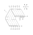
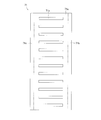
- FIG. 2 is a schematic perspective view of the outdoor heat exchanger 11.
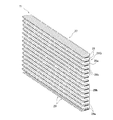
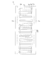
- FIG. 3 is a partially enlarged view of the heat exchange section 27 described later of the outdoor heat exchanger 11.
- FIG. 4 is a schematic view showing a state in which the fin 29, which will be described later, is attached to the flat tube 28 in the heat exchange unit 27.
- FIG. 5 is a schematic configuration diagram of the outdoor heat exchanger 11. The arrow of the heat exchange unit 27 shown in FIG. 5 indicates the flow of the refrigerant during the heating operation (when the outdoor heat exchanger 11 functions as an evaporator).
- the outdoor heat exchanger 11 is a device that exchanges heat between the refrigerant flowing inside and the air.
- the outdoor heat exchanger 11 mainly includes a shunt 22, a flat tube group 28G including a plurality of flat tubes 28, a plurality of fins 29, a liquid header 40, and a gas header 70 (an example of a header). (See FIGS. 4 and 5).
- the shunt 22, the flat tube 28, the fins 29, the liquid header 40, and the gas header 70 are all made of aluminum or an aluminum alloy.
- the outdoor heat exchanger 11 has one row of heat exchange portions 27, and a plurality of flat tubes 28 are not arranged in the air flow direction.
- the exchange takes place.
- the heat exchange units 27 are arranged in the vertical direction, that is, the first heat exchange unit 27a, the second heat exchange unit 27b, the third heat exchange unit 27c, the fourth heat exchange unit 27d, and the fifth heat exchange unit 27e. And, (see FIG. 2).
- the shunt 22 is a mechanism for shunting the refrigerant.
- the shunt 22 is also a mechanism for merging the refrigerant.
- a liquid refrigerant pipe 20 is connected to the shunt 22.
- the shunt 22 has a plurality of shunt pipes 22a to 22e.
- the shunt 22 has a function of shunting the refrigerant flowing into the shunt 22 from the liquid refrigerant pipe 20 into a plurality of shunt pipes 22a to 22e and guiding the refrigerant into a plurality of spaces formed in the liquid header 40.
- the shunt 22 has a function of merging the refrigerant flowing from the liquid header 40 through the shunt pipes 22a to 22e and guiding the refrigerant to the liquid refrigerant pipe 20.
- the flat tube group 28G is an example of a heat transfer tube group.
- the flat tube group 28G includes a plurality of flat tubes 28 (an example of heat transfer tubes) as a plurality of heat transfer tubes.
- the flat tube 28 is a flat heat transfer tube having flat surfaces 28a which are heat transfer surfaces at the top and bottom as shown in FIG.
- a plurality of refrigerant passages 28b through which the refrigerant flows are formed in the flat pipe 28.
- the flat pipe 28 is a flat multi-hole pipe in which a large number of refrigerant passages 28b having a small passage cross-sectional area through which the refrigerant flows are formed.
- the maximum width of the flat pipe 28 in the cross section perpendicular to the refrigerant passage 28b may be 70% or more of the outer diameter of the main gas refrigerant pipe connecting portion 19a, or 85% or more.
- flat pipes 28 extending in the horizontal direction between the liquid header 40 side and the gas header 70 side are arranged vertically in a plurality of stages.
- the flat tube 28 extending between the liquid header 40 side and the gas header 70 side is bent at two points, and the heat exchange portion 27 formed by the flat tube 28 is substantially U-shaped in a plan view. It is formed in a shape (see FIG. 2).
- the flat tube 28 extends in the front-rear direction (an example of the first direction) at the connection point with the gas header 70, and extends in the front-rear direction at the connection point with the liquid header 40.
- the plurality of flat tubes 28 are arranged vertically at regular intervals.
- the plurality of fins 29 are members for increasing the heat transfer area of the outdoor heat exchanger 11.
- Each fin 29 is a plate-shaped member extending in the step direction in which the flat tubes 28 are arranged.
- the outdoor heat exchanger 11 is used in a mode in which a plurality of horizontally extending flat tubes 28 are arranged side by side in the vertical direction. Therefore, when the outdoor heat exchanger 11 is installed in the outdoor unit 2, each fin 29 extends in the vertical direction.
- a plurality of notches 29a extending along the insertion direction of the flat tube 28 are formed in each fin 29 so that a plurality of flat tubes 28 can be inserted.
- the notch 29a extends in the extending direction of the fin 29 and in the direction orthogonal to the thickness direction of the fin 29.
- the notch 29a formed in each fin 29 extends in the horizontal direction.
- the shape of the notch 29a of the fin 29 substantially matches the shape of the outer shape of the cross section of the flat tube 28.
- the notch 29a is formed in the fin 29 with an interval corresponding to the arrangement interval of the flat tubes 28.
- the plurality of fins 29 are arranged side by side along the extending direction of the flat tube 28.
- the adjacent flat tubes 28 are partitioned into a plurality of ventilation passages through which air flows.
- Each fin 29 has a communication portion 29b that communicates vertically with respect to the flat pipe 28 on the upstream side or the downstream side in the air flow direction.
- the communication portion 29b of the fin 29 is located on the windward side of the flat pipe 28.
- each flat tube 28 is connected to the liquid header 40, and the other end of each flat tube 28 is connected to the gas header 70.
- the outdoor heat exchanger 11 is arranged in a casing (not shown) of the outdoor unit 2 so that the axial directions of the substantially columnar liquid header 40 and the gas header 70 substantially coincide with the vertical direction.
- the heat exchange portion 27 of the outdoor heat exchanger 11 is formed in a U-shape in a plan view as shown in FIG.
- the liquid header 40 is arranged near the left front corner of the casing (not shown) of the outdoor unit 2 (see FIG. 2).
- the gas header 70 is arranged near the right front corner of the casing (not shown) of the outdoor unit 2 (see FIG. 2).
- the liquid side internal space 23 of the liquid header 40 is divided into a plurality of subspaces 23a to 23e by a plurality of partition plates 24 (see FIG. 5).
- These plurality of subspaces 23a to 23e are arranged in the vertical direction.
- the sub-spaces 23a to 23e are partitioned by the partition plate 24, so that the sub-spaces 23a to 23e are in a non-communication state in the liquid-side internal space 23 of the liquid header 40.
- Each of the subspaces 23a to 23e is connected to each of the shunt pipes 22a to 22e of the shunt 22 on a one-to-one basis.
- the refrigerants that have reached the subspaces 23a to 23e flow through the shunt pipes 22a to 22e and merge in the shunt 22.
- the refrigerant shunted by the shunt 22 is supplied to the sub-spaces 23a to 23e.
- a single space is formed inside the gas header 70.
- the partition plate for partitioning the vertically arranged spaces as provided in the liquid header 40 is not provided in the gas side internal space 25 of the gas header 70.
- the gas header 70 includes a main gas refrigerant pipe connecting portion 19a (an example of a first pipe and a gas pipe) and a branch that form an end on the gas header 70 side of the first gas refrigerant pipe 19 (an example of a first pipe and a gas pipe).
- a gas refrigerant pipe connection portion 19b (an example of a first pipe and a gas pipe) is connected (see FIG. 5).
- the outer diameter of the main gas refrigerant pipe connecting portion 19a may be, for example, three times or more, or five times or more, the outer diameter of the branched gas refrigerant pipe connecting portion 19b.
- One end of the main gas refrigerant pipe connecting portion 19a communicates with the gas side internal space 25 (an example of a space sandwiched between the first wall portion and the second wall portion) at an intermediate position in the height direction of the gas header 70. It is connected to 70.
- One end of the branched gas refrigerant pipe connecting portion 19b is connected to the gas header 70 so as to communicate with the gas side internal space 25 in the vicinity of the lower end in the height direction of the gas header 70.
- the other end of the branched gas refrigerant pipe connecting portion 19b is connected to the main gas refrigerant pipe connecting portion 19a.
- the branched gas refrigerant pipe connecting portion 19b has an inner diameter smaller than that of the main gas refrigerant pipe connecting portion 19a, and is connected to the gas header 70 below the main gas refrigerant pipe connecting portion 19a to stay near the lower end of the gas header 70. It is possible to draw the refrigerating machine oil into the main gas refrigerant pipe connecting portion 19a.
- the refrigerant flowing through the diversion pipe 22e flows into the sub space 23e.
- the refrigerant that has flowed into the subspaces 23a to 23e of the liquid side internal space 23 flows through the flat pipes 28 connected to the subspaces 23a to 23e.
- the refrigerant flowing through each of the flat tubes 28 evaporates by exchanging heat with air, becomes a gas phase refrigerant, and flows into the gas side internal space 25 of the gas header 70 to merge.
- the refrigerant flows in the refrigerant circuit 6 in the opposite direction to that during the heating operation.
- the high-temperature gas-phase refrigerant flows into the gas-side internal space 25 of the gas header 70 via the main gas refrigerant pipe connecting portion 19a and the branch gas refrigerant pipe connecting portion 19b of the first gas refrigerant pipe 19.
- the refrigerant that has flowed into the gas-side internal space 25 of the gas header 70 is shunted and flows into each flat pipe 28.
- the refrigerant that has flowed into the flat pipes 28 passes through the flat pipes 28 and flows into the subspaces 23a to 23e of the liquid side internal space 23 of the liquid header 40.
- the refrigerant that has flowed into the subspaces 23a to 23e of the liquid side internal space 23 merges with the shunt 22 and flows out to the liquid refrigerant pipe 20.
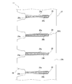
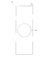
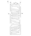
- FIG. 6 shows a side view external configuration diagram showing a state in which the main gas refrigerant pipe connecting portion 19a is connected to the gas header 70.
- FIG. 7 shows a sectional view of the gas header 70 in a plan view.
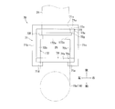
- FIG. 8 is a plan sectional view showing how the main gas refrigerant pipe connecting portion 19a and the flat pipe 28 are connected to the gas header 70.
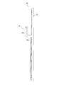
- FIG. 9 shows a schematic view of the first member 71 as viewed from the rear side.
- FIG. 10 shows a schematic view of the third member 73 as viewed from the rear side.
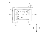
- FIG. 11 shows a schematic view of the second member 72 as viewed from the rear side.
- FIG. 12 shows an external perspective view of the second member 72.
- FIG. 13 shows a schematic view of the fourth member 74 as viewed from the rear side.
- FIG. 14 shows a projection drawing showing the positional relationship of each opening when the first member 71 is viewed from the rear side.
- the gas header 70 has a first member 71, a second member 72, a third member 73, a fourth member 74, and an upper end lid member and a lower end lid member (not shown).
- the gas header 70 is configured by brazing the first member 71, the second member 72, the third member 73, the fourth member 74, the upper end lid member, and the lower end lid member to each other.
- the gas header 70 is configured so that the outer shape in a plan view has a substantially quadrangular shape having a connection point of the flat pipe 28 as one side.
- the first member 71 is a member that mainly constitutes the periphery of the outer shape of the gas header 70 together with the fourth member 74 described later.
- the first member 71 preferably has a clad layer having a brazing material formed on its surface.
- the first member 71 has a flat tube connecting plate 71a, a first outer wall 71b, a second outer wall 71c, a first claw portion 71d, and a second claw portion 71e.
- the first member 71 of the present embodiment can be formed by bending one sheet metal obtained by rolling with the longitudinal direction of the gas header 70 as a crease.
- the plate thickness of each portion of the first member 71 is uniform and has the first thickness.
- the flat tube connecting plate 71a (an example of the first part) is a flat plate-shaped part that extends in the vertical and horizontal directions.
- a plurality of flat tube connecting openings 71x (an example of the first opening) arranged side by side in the vertical direction are formed on the flat tube connecting plate 71a.
- Each flat tube connecting opening 71x is an opening penetrating in the thickness direction of the flat tube connecting plate 71a.
- the flat tube 28 is joined by brazing in a state where the flat tube 28 is inserted into the flat tube connection opening 71x so that one end of the flat tube 28 completely passes through. In the brazed joint state, the entire inner peripheral surface of the flat tube connection opening 71x and the entire outer peripheral surface of the flat tube 28 are in contact with each other.
- the first thickness which is the thickness of the first member 71 including the flat tube connecting plate 71a
- the flat tube connecting opening 71x The length of the inner peripheral surface in the plate thickness direction can be shortened. Therefore, when the flat pipe 28 is inserted into the flat pipe connection opening 71x in the stage before joining by brazing, between the inner peripheral surface of the flat pipe connection opening 71x and the outer peripheral surface of the flat pipe 28. It is possible to suppress the friction that occurs and facilitate the insertion work.
- the first outer wall 71b (an example of the wall surface portion) is formed from the front surface of the end portion on the left side (inside of the outdoor unit 2, the liquid header 40 side) of the flat pipe connecting plate 71a, along the first inner wall 72b described later. It is a flat portion extending toward the first gas refrigerant pipe 19.
- the second outer wall 71c (an example of the wall surface portion) is the second inner wall 72c described later from the front surface of the end portion on the right side of the flat pipe connecting plate 71a (outside of the outdoor unit 2, opposite to the liquid header 40 side). It is a plane-shaped portion extending toward the first gas refrigerant pipe 19 along the above.
- the first claw portion 71d (an example of the claw portion) is a portion extending from the front end portion of the first outer wall 71b toward the right side.
- the second claw portion 71e (an example of the claw portion) is a portion extending from the front end portion of the second outer wall 71c toward the left side.
- the first claw portion 71d and the second claw portion 71e are the first outer walls, respectively, in a state before the second member 72, the third member 73, and the fourth member 74 are arranged inside the first member 71 in a plan view. It is in a state of extending on the extension of 71b and the second outer wall 71c. Then, with the second member 72, the third member 73, and the fourth member 74 arranged inside the first member 71 in a plan view, the first claw portion 71d and the second claw portion 71e are brought close to each other. By bending, the second member 72, the third member 73, and the fourth member 74 are crimped by the first member 71 to be fixed to each other. Then, in this state, brazing is performed in a furnace or the like, so that the members are joined by brazing and completely fixed.
- the third member 73 is laminated so as to face and contact the surface of the flat pipe connecting plate 71a of the first member 71 on the side to which the first gas refrigerant pipe 19 is connected. It is a flat plate-shaped part that spreads in the direction and in the left-right direction.
- the left-right length of the third member 73 is the same as the left-right length of the portion of the flat pipe connecting plate 71a of the first member 71 excluding both ends.
- the third member 73 has a clad layer having a brazing material formed on the surface thereof.
- the third member 73 has an inner plate 73a and a plurality of internal openings 73x.
- the inner plate 73a has a flat plate shape that extends in the vertical direction and in the horizontal direction.
- the plurality of internal openings 73x are arranged side by side in the vertical direction, and are openings that penetrate the internal plate 73a in the plate thickness direction.
- Each internal opening 73x of the third member 73 is a larger opening than each flat pipe connecting opening 71x formed in the flat pipe connecting plate 71a of the first member 71.
- the outer edge of each internal opening 73x of the third member 73 is in the stacking direction of each member, more specifically in the front-rear direction. , It is configured to be located outside the outer edge of each flat pipe connecting opening 71x formed in the flat pipe connecting plate 71a of the first member 71.
- each internal opening 73x of the third member 73 may be separated from the upper and lower portions of the outer edge of each flat pipe connection opening 71x of the flat pipe connecting plate 71a by 2 mm or more. It is preferable that they are separated.
- the second member 72 is arranged between the flat pipe connecting plate 71a of the first member 71 and the main gas refrigerant pipe connecting portion 19a in the front-rear direction.
- the second member 72 is a member having a substantially U-shape in a plan view.
- the gas-side internal space 25 is formed inside the second member 72, more specifically, in a space surrounded by the second member 72, the third member 73, and the end of the flat pipe 28.
- the maximum thickness of the second member 72 is preferably larger than the thickness of the first member 71. This makes it possible to increase the withstand voltage strength of the gas header 70.
- the second member 72 is not particularly limited, but is preferably obtained through an extrusion molding step in which the longitudinal direction of the gas header 70 is the extrusion direction. According to the extrusion molding, it is possible to easily construct the portions having different thicknesses. Further, since a sheet metal having a large plate thickness is relatively expensive, it is possible to reduce the cost by forming a thick second member 72 by extrusion molding.
- the second member 72 obtained by extrusion molding may not be provided with a clad layer having a brazing material.
- the second member 72 includes a first inner wall 72b, a second inner wall 72c, a connecting portion 72a, a first convex portion 72d, a second convex portion 72e, a first edge portion 72f, and a second edge portion 72g. ,have.
- the connecting portion 72a is a plate-shaped portion that faces the surface of the third member 73 on the main gas refrigerant pipe connecting portion 19a side and extends in the vertical and horizontal directions.
- the connecting portion 72a is located on the main gas refrigerant pipe connecting portion 19a side of the gas header 70.
- the connecting portion 72a is formed with an internal gas pipe connecting opening 72x which is an opening to which the end portion of the main gas refrigerant pipe connecting portion 19a is connected and which is an opening penetrating the connecting portion 72a in the plate thickness direction.
- the connecting portion 72a is formed with an opening (not shown) through which the end portion of the branched gas refrigerant pipe connecting portion 19b is connected and penetrates in the plate thickness direction of the connecting portion 72a.
- the first inner wall 72b (an example of the first wall portion) extends from the left end of the connecting portion 72a (inside of the outdoor unit 2, on the liquid header 40 side) toward the rear side where the flat tube 28 extends. It is a flat part that has been put out.
- the left side surface of the first inner wall 72b is arranged so as to be in surface contact with the right side surface of the first outer wall 71b of the first member 71.
- the second inner wall 72c (an example of the second wall portion) is the rear side on which the flat tube 28 extends from the end of the right side of the connecting portion 72a (outside of the outdoor unit 2, opposite to the liquid header 40 side). It is a flat-shaped part extending toward.
- the right surface of the second inner wall 72c is arranged so as to be in surface contact with the left surface of the second outer wall 71c of the first member 71.
- the first inner wall 72b and the second inner wall 72c face each other.
- the front end of the first inner wall 72b and the front end of the second inner wall 72c are also opposed to each other.
- the thicknesses of the connecting portion 72a, the first inner wall 72b, and the second inner wall 72c are all larger than the thickness of the first member 71, and may be 1.5 times or more, preferably 2 times or more.
- the length in the direction in which the flat pipe 28 of the first inner wall 72b and the second inner wall 72c extends is the length in the direction in which the flat pipe 28 of the connecting portion 72a extends (front-back direction). It may be 3 times or more, preferably 5 times or more.
- the connecting portion 72a connects the first inner wall 72b and the second inner wall 72c.
- the connecting portion 72a is the front end portion of the first inner wall 72b (the end on the main gas refrigerant pipe connecting portion 19a side) and the front end portion of the second inner wall 72c (on the main gas refrigerant pipe connecting portion 19a side). It is connected to the end).
- the connecting portion 72a is preferably in the left-right direction (an example of the third direction, and the third direction is orthogonal to both the first direction and the second direction in the plan view of the gas header 70, and the first direction. It is more preferable that the second direction and the third direction are orthogonal to each other.)
- the first edge portion 72f is provided on the rear side (flat tube 28 side) of the first inner wall 72b.
- the left side surface of the first edge portion 72f is formed on the same surface as the left side surface of the first inner wall 72b, and is in surface contact with the right side surface of the first outer wall 71b of the first member 71.
- the rear end of the first edge 72f is in contact with the front surface of the third member 73.
- the thickness of the first edge portion 72f (width in the left-right direction) is smaller than the thickness of the first inner wall 72b (width in the left-right direction).
- the contact point between the first edge portion 72f and the front surface of the third member 73 is located on the left side of the flat pipe 28, and is from the left end portion of the internal opening 73x (an example of the second opening) of the third member 73. Is also located on the left side.
- the second edge portion 72g is provided on the rear side (flat tube 28 side) of the second inner wall 72c.
- the right side surface of the second edge portion 72g is formed on the same surface as the right side surface of the second inner wall 72c, and is in surface contact with the left side surface of the second outer wall 71c of the first member 71.
- the rear end of the second edge 72g is in contact with the front surface of the third member 73.
- the thickness of the second edge portion 72g (width in the left-right direction) is smaller than the thickness of the second inner wall 72c (width in the left-right direction).
- the contact point between the second edge portion 72g and the front surface of the third member 73 is located on the right side of the flat pipe 28 and on the right side of the right end portion of the internal opening 73x of the third member 73. ..
- the length between the first edge portion 72f and the second edge portion 72g is wider than the width of the flat pipe 28, wider than the width of the flat pipe connection opening 71x of the first member 71, and the third It is wider than the width of the internal opening 73x of the member 73.
- Both the first edge portion 72f and the second edge portion 72g extend from the upper end to the lower end of the gas header 70.
- the first convex portion 72d is a convex portion which is a rear end portion of the first inner wall 72b and extends from a portion in front of the first edge portion 72f toward the right side (second inner wall 72c side).
- the first convex portion 72d extends from the upper end to the lower end of the gas header 70.
- the right end of the first convex portion 72d is located on the right side of the left end of the internal opening 73x of the third member 73, and is located on the right side of the left end of the flat pipe 28.
- the first convex portion 72d is located on the flat tube 28 side with respect to the center of the second member 72 in the front-rear direction.
- the second convex portion 72e is a convex portion which is a rear end portion of the second inner wall 72c and extends from a portion in front of the second edge portion 72g toward the left side (first inner wall 72b side).
- the second convex portion 72e extends from the upper end to the lower end of the gas header 70.
- the left end of the second convex portion 72e is located on the left side of the right end of the internal opening 73x of the third member 73, and is located on the left side of the right end of the flat tube 28.
- the second convex portion 72e is located on the flat tube 28 side with respect to the center of the second member 72 in the front-rear direction.
- the shortest distance (distance in the left-right direction) between the first convex portion 72d and the second convex portion 72e is smaller than the maximum width in the cross section perpendicular to each refrigerant passage 28b of the flat pipe 28.
- the fourth member 74 is a flat plate-shaped portion that is laminated so as to face and contact the front surface of the connecting portion 72a of the second member 72, and extends in the vertical and horizontal directions. Is.
- the left and right lengths of the fourth member 74 are the same as the left and right lengths of the third member 73, and are the same as the left and right lengths of the flat pipe connecting plate 71a of the first member 71 excluding both ends. is there.
- the fourth member 74 preferably has a clad layer having a brazing material formed on its surface. Since the fourth member 74 is a plate-shaped member, it is easy to provide a clad layer having a brazing material on the surface. Therefore, for example, even when the second member 72 is not provided with the clad layer having the brazing material as in the case where the second member 72 is obtained by extrusion molding, the second member 72 is provided on the fourth member 74.
- the brazed material makes it possible to join the second member 72 to another member by brazing.
- the fourth member 74 has an outer plate 74a and an external gas pipe connection opening 74x.
- the outer plate 74a has a flat plate shape that extends in the vertical direction and in the horizontal direction.
- the external gas pipe connection opening 74x is an opening to which the end portion of the main gas refrigerant pipe connection portion 19a is connected, and is an opening penetrating the outer plate 74a in the plate thickness direction.
- an opening (not shown) is formed to which the end portion of the branched gas refrigerant pipe connecting portion 19b is connected and penetrates in the plate thickness direction of the outer plate 74a. ..
- the main gas refrigerant pipe connecting portion 19a and the branch gas refrigerant pipe connecting portion 19b are gas sandwiched between the external gas pipe connecting opening 74x, the internal gas pipe connecting opening 72x, the first inner wall 72b, and the second inner wall 72c. It is in a state of communicating with the inner side surface of the flat pipe connecting plate 71a of the first member 71 via the side internal space 25.
- the front surface of the fourth member 74 is in contact with the first claw portion 71d and the second claw portion 71e of the first member 71 and is crimped.
- the first inner wall 72b is the rear side in the direction in which the flat pipe 28 extends from the left end of the connecting portion 72a.
- the second inner wall 72c extends from the right end of the connecting portion 72a toward the rear side.
- the second member 72 of the gas header 70n of the present embodiment is one member formed by extrusion molding. Therefore, it is possible to reduce the number of parts required to secure a wide internal space 25 on the gas side without causing problems such as punching.
- the first inner wall 72b and the second inner wall 72c are formed so as to extend in the direction in which the flat pipe 28 extends, but the first inner wall 72b and the second inner wall
- the 72c is connected to the 72c via a connecting portion 72a, and the connecting portion 72a, the first inner wall 72b, and the second inner wall 72c are integrated. This makes it possible to increase the strength of the second member 72 and increase the pressure resistance strength of the gas header 70.
- the connecting portion 72a is provided so as to connect the front end portion of the first inner wall 72b and the front end portion of the second inner wall 72c. Therefore, it is easier to secure a wider internal space 25 on the gas side as compared with the case where the intermediate portion of the first inner wall 72b in the front-rear direction and the intermediate portion of the second inner wall 72c in the front-rear direction are connected.
- the flat pipe connecting plate 71a and the third member 73 of the first member 71 are formed in a plate shape. Then, the flat tube 28 is inserted perpendicularly to the flat tube connecting plate 71a of the first member 71 and the third member 73.
- the first outer wall 71b and the second outer wall 71c extend vertically from the left and right ends of the flat pipe connecting plate 71a of the first member 71, and the second member 72 extends from the left and right ends of the third member 73.
- the first inner wall 72b and the second inner wall 72c are vertically joined.
- the gas header 70 of the outdoor heat exchanger 11 of the present embodiment it is possible to reduce the wasted space in which the refrigerant stays around the end of the flat pipe 28. As a result, it is possible to reduce the pressure loss of the gas refrigerant flowing in the gas header 70 and suppress the decrease in the flow velocity of the refrigerant in the gas header 70.
- the first member 71 including the flat pipe connecting plate 71a is formed relatively thinly. Therefore, when the flat pipe 28 is inserted into the flat pipe connection opening 71x in the stage before joining by brazing, between the inner peripheral surface of the flat pipe connection opening 71x and the outer peripheral surface of the flat pipe 28. It is possible to suppress the friction generated and facilitate the insertion work.
- the flat pipe connecting plate 71a is further laminated with the third member 73 in the plate thickness direction. Therefore, it is possible to increase the pressure resistance strength of the portion of the gas header 70 on the side to which the flat pipe 28 is connected.
- each internal opening 73x of the third member 73 is configured to be located outside the outer edge of each flat pipe connecting opening 71x formed in the flat pipe connecting plate 71a of the first member 71. Therefore, at the time of brazing, even if the brazing material interposed between the flat tube connection opening 71x of the flat tube connection plate 71a and the flat tube 28 may overflow toward the end side of the flat tube 28. The overflowing brazing material is sent to the space outside the flat tube 28 and inside each internal opening 73x of the third member 73. Therefore, it is possible to prevent the refrigerant passage 28b of the flat pipe 28 from being filled with the brazing material.
- the shortest distance (distance in the left-right direction) between the first convex portion 72d and the second convex portion 72e of the second member 72 is the refrigerant passage of the flat pipe 28. It is smaller than the maximum width in the cross section perpendicular to 28b. Therefore, it is possible to specify the degree of insertion of the flat pipe 28 in the gas header 70.
- the first convex portion 72d and the second convex portion 72e, which define the degree of insertion of the flat tube 28, are both located on the flat tube 28 side with respect to the center of the second member 72 in the front-rear direction. Therefore, it is possible to secure a sufficiently wide internal space 25 on the gas side.
- FIG. 15 is a plan sectional view showing how the main gas refrigerant pipe connecting portion 19a and the flat pipe 28 are connected to the gas header 70.
- FIG. 16 is a projection drawing showing the positional relationship of each opening when the second member 172 is viewed from the rear side.
- the second member 172 has a connecting portion 172a instead of the connecting portion 72a of the second member 72 of the above embodiment.
- the connecting portion 172a is a portion between both ends of the first inner wall 72b in the front-rear direction (the direction in which the flat tube 28 extends) and the second inner wall 72c in the front-rear direction (direction in which the flat tube 28 extends). Connect the ends with the part between the ends.
- the connecting portion 172a connects the first inner wall 72b and the second inner wall 72c at a position other than the end portion, it is possible to increase the structural strength of the second member 172.
- the connecting portion 172a is a plate-shaped portion extending in the vertical direction and the horizontal direction.
- the connecting portion 172a has a plurality of internal gas pipe connecting openings 172x arranged in the vertical direction.
- Each internal gas pipe connection opening 172x is provided so as to correspond to each flat pipe 28.
- the vertical size of each internal gas pipe connection opening 172x is larger than the vertical size of each flat pipe connection opening 71x of each flat pipe 28 or the first member 71, but the width of each internal gas pipe connection opening 172x.
- the size in the direction (left-right direction) is smaller than the size in the width direction (left-right direction) of each flat pipe connection opening 71x of each flat pipe 28 and the first member 71. This makes it possible to specify the degree of insertion of the flat tube 28. Since the degree of insertion of the flat pipe 28 can be defined by the edge of the internal gas pipe connection opening 172x, the first convex portion 72d and the second convex portion 72e as in the second member 72 of the above embodiment
- the third member 73 and / or the fourth member 74 in the above embodiment may be omitted.
Abstract
内部の空間を広く確保する場合においても部品点数を少なく抑えることが可能なヘッダを有する熱交換器およびヒートポンプ装置を提供する。冷媒を流す第1ガス冷媒管(19)が接続される室外熱交換器(11)であって、複数の扁平管(28)とガスヘッダ(70)を備え、ガスヘッダ(70)は、複数の扁平管(28)が接続される扁平管接続板(71a)を有する第1部材(71)と、第1ガス冷媒管(19)と扁平管接続板(71a)との間に配置される第2部材(72)と、を有しており、第2部材(72)は、扁平管(28)が延びる第1方向に沿う第1内壁(72b)および第2内壁(72c)と、第1内壁(72b)と第2内壁(72c)とを連結する連結部(72a)と、を有しており、第1ガス冷媒管(19)と扁平管(28)とは、第1内壁(72b)と第2内壁(72c)で挟まれる空間を介して連通する。
Description
本開示は、熱交換器およびヒートポンプ装置に関する。
従来より、空気調和装置等の冷媒サイクル装置では、内部を冷媒が流れる伝熱管がヘッダに対して接続されることで構成された熱交換器が用いられている。
例えば、特許文献1(国際公開第2015/004719号)に記載の熱交換器では、開口が形成された板状部材を複数積層させて構成したガスヘッダが用いられている。
ここで、上記のように開口が形成された板状部材を複数積層する場合においてヘッダ内の空間を広く確保しようとすると、無数の板状部材が必要になってしまう。
本開示の内容は、内部の空間を広く確保する場合においても部品点数を少なく抑えることが可能なヘッダを有する熱交換器およびヒートポンプ装置を提供することを目的とする。
第1観点に係る熱交換器は、冷媒を流す第1配管が接続される熱交換器であって、複数の伝熱管と、複数の伝熱管が接続されたヘッダと、を備えている。ヘッダは、第1部材と第2部材を有している。第1部材は、複数の伝熱管が接続される第1部分を有している。第2部材は、第1配管と第1部分との間に配置される。第2部材は、第1壁部と第2壁部と連結部とを有している。第1壁部と第2壁部は、いずれも、伝熱管が延びる第1方向に沿っている。連結部は、第1壁部と第2壁部とを連結する。第1配管と伝熱管とが、第1壁部と第2壁部で挟まれる空間を介して連通する。
この熱交換器は、第2部材が有する第1壁部と第2壁部とが、いずれも、伝熱管が延びる第1方向に沿っている。これにより、第2部材によって、第1壁部と第2壁部で挟まれる空間を確保することができている。
第2観点に係る熱交換器は、第1観点の熱交換器であって、連結部は、第1方向における第1壁部の端部と、第1方向における第2壁部の端部と、を連結する。
なお、連結部は、第1方向における第1壁部の端部と、第1方向における第2壁部の端部と、を連結させればよく、例えば、第1方向のうちの伝熱管側とは反対側において第1壁部と第2壁部とを連結していてもよい。
この熱交換器は、連結部が第1壁部と第2壁部の端部同士を連結しているため、第1壁部と第2壁部とで挟まれる空間を広く確保しやすい。
第3観点に係る熱交換器は、第1観点の熱交換器であって、連結部は、第1方向における第1壁部の両端以外の部分と、第1方向における第2壁部の両端以外の部分と、を連結する。
この熱交換器は、連結部が第1壁部と第2壁部の端部以外の部分同士を連結しているため、第2部材の強度を高めることが可能になる。
第4観点に係る熱交換器は、第1観点から第3観点のいずれかの熱交換器であって、第1部分は、板状である。
なお、第1部材は、伝熱管が延びている方向に対して垂直に広がった板状であることが好ましい。
この熱交換器は、板状の第1部分に対して伝熱管が接続されているため、伝熱管のうちのヘッダ内の部分の周囲に無駄なスペースが生じることを抑制できる。
第5観点に係る熱交換器は、第1観点から第4観点のいずれかの熱交換器であって、第2部材は、第1凸部と、第2凸部とを有している。第1凸部は、連結部よりも伝熱管に近い位置において、第1壁部から第2壁部に向けて延び出している。第2凸部は、連結部よりも伝熱管に近い位置において、第2壁部から第1壁部に向けて延び出している。第1凸部と第2凸部の最短距離は、伝熱管の断面における最大幅よりも小さい。
この熱交換器は、第2部材が有する第1凸部と第2凸部によって、伝熱管がヘッダに差し込まれる程度を規定することが可能になる。
第6観点に係る熱交換器は、第5観点の熱交換器であって、連結部は、第1壁部の第1方向における中心よりも第1配管に近い位置と、第2壁部の第1方向における中心よりも第1配管に近い位置と、を連結させている。第1凸部は、第1壁部の第1方向における中心よりも伝熱管に近い位置に設けられている。第2凸部は、第2壁部の第1方向における中心よりも伝熱管に近い位置に設けられている。
この熱交換器は、伝熱管の端部と連結部と第1壁部と第2壁部とで囲まれる空間を広く確保することが可能になる。
第7観点に係る熱交換器は、第1観点から第6観点のいずれかの熱交換器であって、第3部材をさらに備えている。第3部材は、第1部材の第1部分のうち、第2部材が設けられている側に面するように設けられている。第1部分は、複数の伝熱管が挿入される複数の第1開口を有している。第3部材は、複数の伝熱管が挿入される複数の第2開口を有している。第1開口と第2開口は、第1方向視において重なる部分を有している。
この熱交換器は、第1部分が有する第1開口において、挿入された伝熱管を固定することが可能になる。ここで、第1部分に対して第3部材が重ねて配置されているため、第1部分と第3部材が重なって構成される部分の厚みを確保し、強度を高めることができている。このため、第1部分を薄く形成することで、伝熱管を挿入する際に生じうる伝熱管周囲面と第1開口との間の摩擦を低減させる場合であっても、第1部分と第3部材が重なって構成される部分の強度を確保することが可能になる。
第8観点に係る熱交換器は、第7観点の熱交換器であって、第1方向視において、第3部材の各第2開口は、第1部分の各第1開口よりも大きい。第1方向視において、第3部材の各第2開口の縁は、第1部分の各第1開口の縁の外側に位置している。
この熱交換器は、第1部分と第3部材とをロウ付けにより接合させる場合において、過剰なロウ材が生じたとしても、伝熱管の外側であって第2開口の内側の領域に移動させることが可能であるため、伝熱管の流路が埋められてしまうことを抑制することができる。
第9観点に係る熱交換器は、第1観点から第8観点のいずれかの熱交換器であって、第1配管が接続される第4部材をさらに備えている。第1部材は、各壁面部と各爪部を有している。各壁面部は、第1部分の両端部からそれぞれ第1壁部および第2壁部に沿って第1配管に向かって延びる。各爪部は、それぞれの壁面部のうち第1部分とは反対側の端部において互いに近づくように延びている。第4部材のうち第1部分とは反対側の面が、爪部と接している。
なお、第1部分の両端部とは、第1部分の長手方向視における第1部分の両端部であってよい。
この熱交換器は、第4部材を第1部材の爪によりカシメることで、第2部材の周囲を第1部材と第4部材によって覆うことが可能になる。
なお、第1部材と第4部材において孔食性のある金属を含ませた場合には、ヘッダの周囲の耐食性を向上させることが可能になる。
第10観点に係る熱交換器は、第1観点から第9観点のいずれかの熱交換器であって、伝熱管は、扁平管である。扁平管は、扁平な面を有している。
なお、扁平管は、第1部分の長手方向の幅が第1部分の長手方向に垂直な方向の幅よりも短い断面形状を有していることが好ましい。
第11観点に係る熱交換器は、第1観点から第10観点のいずれかの熱交換器であって、第1配管は、ガス配管である。
なお、ガス配管に流れる冷媒は、ガス状態の冷媒に限られず、気液二相状態の冷媒であってもよい。このような気液二相状態の冷媒としては、例えば、乾き度が0.8以上の冷媒であることが好ましい。
この熱交換器は、ガス管が接続されるヘッダについて耐圧強度を高めやすい。
第12観点に係るヒートポンプ装置は、第1観点から第11観点のいずれかの熱交換器を搭載する。
以下、本開示の熱交換器が採用された空気調和装置の実施形態について説明する。
(1)空気調和装置の構成
空気調和装置1について図面を参照しながら説明する。
空気調和装置1について図面を参照しながら説明する。
図1は、本開示の一実施形態に係る熱交換器を室外熱交換器11として有する空気調和装置1の概略構成図である。
空気調和装置1(ヒートポンプ装置の一例)は、蒸気圧縮式の冷凍サイクルを行うことにより、空調対象空間の冷房および暖房を行う装置である。空調対象空間は、例えば、オフィスビル、商業施設、住居等の建物内の空間である。なお、空気調和装置は、冷媒サイクル装置の一例に過ぎず、本開示の熱交換器は、他の冷媒サイクル装置、例えば、冷蔵庫、冷凍庫、給湯器、床暖房装置等に使用されるものであってもよい。
空気調和装置1は、図1のように、主として、室外ユニット2と、室内ユニット9と、液冷媒連絡管4およびガス冷媒連絡管5と、室外ユニット2および室内ユニット9を構成する機器を制御する制御部3と、を有する。液冷媒連絡管4およびガス冷媒連絡管5は、室外ユニット2と室内ユニット9とを接続する冷媒連絡管である。空気調和装置1では、室外ユニット2と室内ユニット9とが、液冷媒連絡管4およびガス冷媒連絡管5を介して接続されることで、冷媒回路6が構成される。
なお、図1では、空気調和装置1は室内ユニット9を1台有するが、空気調和装置1は、液冷媒連絡管4およびガス冷媒連絡管5によって室外ユニット2に対して互いに並列に接続される複数の室内ユニット9を有してもよい。また、空気調和装置1は複数の室外ユニット2を有してもよい。また、空気調和装置1は、室外ユニット2と室内ユニット9とが一体に形成されている、一体型の空気調和装置であってもよい。
(1-1)室外ユニット
室外ユニット2は、空調対象空間外、例えば、建物の屋上や建物の壁面近傍等に設置される。
室外ユニット2は、空調対象空間外、例えば、建物の屋上や建物の壁面近傍等に設置される。
室外ユニット2は、主として、アキュムレータ7、圧縮機8、四路切換弁10、室外熱交換器11、膨張機構12、液側閉鎖弁13およびガス側閉鎖弁14、および室外ファン16を有している(図1参照)。
室外ユニット2は、冷媒回路6を構成する各種機器を接続する冷媒管として、吸入管17、吐出管18、第1ガス冷媒管19、液冷媒管20、および第2ガス冷媒管21を主に有する(図1参照)。吸入管17は、四路切換弁10と圧縮機8の吸入側とを接続する。吸入管17には、アキュムレータ7が設けられている。吐出管18は、圧縮機8の吐出側と四路切換弁10とを接続する。第1ガス冷媒管19は、四路切換弁10と室外熱交換器11のガス側とを接続する。液冷媒管20は、室外熱交換器11の液側と液側閉鎖弁13とを接続する。液冷媒管20には、膨張機構12が設けられている。第2ガス冷媒管21は、四路切換弁10とガス側閉鎖弁14とを接続する。
圧縮機8は、吸入管17から冷凍サイクルにおける低圧の冷媒を吸入し、図示しない圧縮機構で冷媒を圧縮して、圧縮した冷媒を吐出管18へと吐出する機器である。
四路切換弁10は、冷媒の流向を切り換えることで、冷媒回路6の状態を、冷房運転の状態と、暖房運転の状態との間で変更する機構である。冷媒回路6が冷房運転の状態にある時には、室外熱交換器11が冷媒の放熱器(凝縮器)として機能し、室内熱交換器91が冷媒の蒸発器として機能する。冷媒回路6が暖房運転の状態にある時には、室外熱交換器11が冷媒の蒸発器として機能し、室内熱交換器91が冷媒の凝縮器として機能する。四路切換弁10が冷媒回路6の状態を冷房運転の状態とする場合には、四路切換弁10は、吸入管17を第2ガス冷媒管21と連通させ、吐出管18を第1ガス冷媒管19と連通させる(図1の四路切換弁10内の実線参照)。四路切換弁10が冷媒回路6の状態を暖房運転の状態とする場合には、四路切換弁10は、吸入管17を第1ガス冷媒管19と連通させ、吐出管18を第2ガス冷媒管21と連通させる(図1中の四路切換弁10内の破線参照)。
室外熱交換器11(熱交換器の一例)は、内部を流れる冷媒と室外ユニット2の設置場所の空気(熱源空気)との間で熱交換を行わせる機器である。室外熱交換器11の詳細については後述する。
膨張機構12は、冷媒回路6において室外熱交換器11と室内熱交換器91との間に配置される。本実施形態では、膨張機構12は、室外熱交換器11と液側閉鎖弁13との間の液冷媒管20に配置されている。なお、本空気調和装置1では、膨張機構12が室外ユニット2に設けられているが、これに代えて、膨張機構12は後述する室内ユニット9に設けられていてもよい。膨張機構12は、液冷媒管20を流れる冷媒の圧力や流量の調節を行う機構である。本実施形態では、膨張機構12は開度可変の電子膨張弁であるが、膨張機構12は感温筒式の膨張弁やキャピラリチューブであってもよい。
アキュムレータ7は、流入する冷媒をガス冷媒と液冷媒とに分離する気液分離機能を有する容器である。また、アキュムレータ7は、運転負荷の変動等に応じて発生する余剰冷媒の貯留機能を有する容器である。
液側閉鎖弁13は、液冷媒管20と液冷媒連絡管4との接続部に設けられている弁である。ガス側閉鎖弁14は、第2ガス冷媒管21とガス冷媒連絡管5との接続部に設けられている弁である。液側閉鎖弁13およびガス側閉鎖弁14は、空気調和装置1の運転時には開かれている。
室外ファン16は、図示しない室外ユニット2のケーシング内に外部の熱源空気を吸入して室外熱交換器11に供給し、室外熱交換器11において冷媒と熱交換した空気を室外ユニット2のケーシング外に排出するためのファンである。室外ファン16は、例えばプロペラファンである。
(1-2)室内ユニット
室内ユニット9は、空調対象空間に設置されるユニットである。室内ユニット9は、例えば天井埋込式のユニットであるが、天井吊下式、壁掛式、または床置式のユニットであってもよい。また、室内ユニット9は、空調対象空間の外に設置されてもよい。例えば、室内ユニット9は、屋根裏、機械室、ガレージ等に設置されてもよい。この場合、室内熱交換器91において冷媒と熱交換した空気を、室内ユニット9から空調対象空間へと供給する空気通路が設置される。空気通路は、例えばダクトである。
室内ユニット9は、空調対象空間に設置されるユニットである。室内ユニット9は、例えば天井埋込式のユニットであるが、天井吊下式、壁掛式、または床置式のユニットであってもよい。また、室内ユニット9は、空調対象空間の外に設置されてもよい。例えば、室内ユニット9は、屋根裏、機械室、ガレージ等に設置されてもよい。この場合、室内熱交換器91において冷媒と熱交換した空気を、室内ユニット9から空調対象空間へと供給する空気通路が設置される。空気通路は、例えばダクトである。
室内ユニット9は、室内熱交換器91および室内ファン92を主に有する(図1参照)。
室内熱交換器91では、室内熱交換器91を流れる冷媒と、空調対象空間の空気との間で熱交換が行われる。室内熱交換器91は、タイプを限定するものではないが、例えば、図示しない複数の伝熱管とフィンとを有するフィン・アンド・チューブ型熱交換器である。室内熱交換器91の一端は、冷媒配管を介して液冷媒連絡管4と接続される。室内熱交換器91の他端は、冷媒配管を介してガス冷媒連絡管5と接続される。
室内ファン92は、室内ユニット9のケーシング(図示せず)内に空調対象空間内の空気を吸入して室内熱交換器91に供給し、室内熱交換器91において冷媒と熱交換した空気を空調対象空間へと吹き出す機構である。室内ファン92は、例えばターボファンである。ただし、室内ファン92のタイプは、ターボファンに限定されるものではなく適宜選択されればよい。
(1-3)制御部
制御部3は、空気調和装置1を構成する各種機器の動作を制御する機能部である。
制御部3は、空気調和装置1を構成する各種機器の動作を制御する機能部である。
制御部3は、例えば、室外ユニット2の室外制御ユニット(図示せず)と、室内ユニット9の室内制御ユニット(図示せず)とが、伝送線(図示せず)を介して通信可能に接続されて構成されている。室外制御ユニットおよび室内制御ユニットは、例えば、マイクロコンピュータや、マイクロコンピュータが実施可能な、空気調和装置1の制御用の各種プログラムが記憶されているメモリ等を有するユニットである。なお、図1では、便宜上、室外ユニット2および室内ユニット9とは離れた位置に制御部3を描画している。
なお、制御部3の機能は、室外制御ユニットおよび室内制御ユニットが協働することで実現される必要はない。例えば、制御部3の機能は、室外制御ユニットおよび室内制御ユニットのいずれか一方により実現されてもよいし、室外制御ユニットおよび室内制御ユニットとは異なる図示しない制御装置が制御部3の機能の一部または全部を実現してもよい。
制御部3は、図1に示されるように、圧縮機8、四路切換弁10、膨張機構12、室外ファン16および室内ファン92を含む、室外ユニット2および室内ユニット9の各種機器と電気的に接続されている。また、制御部3は、室外ユニット2および室内ユニット9に設けられた図示しない各種センサと電気的に接続されている。また、制御部3は、空気調和装置1のユーザが操作する図示しないリモコンと通信可能に構成されている。
制御部3は、各種センサの計測信号や、図示しないリモコンから受信する指令等に基づいて、空気調和装置1の運転および停止や、空気調和装置1を構成する各種機器の動作を制御する。
(2)室外熱交換器の構成
図面を参照しながら、室外熱交換器11の構成について説明する。
図面を参照しながら、室外熱交換器11の構成について説明する。
図2は、室外熱交換器11の概略斜視図である。図3は、室外熱交換器11の、後述する熱交換部27の部分拡大図である。図4は、熱交換部27における後述するフィン29の扁平管28に対する取付状態を示す概略図である。図5は、室外熱交換器11の概略構成図である。図5に示した熱交換部27の矢印は、暖房運転時(室外熱交換器11が蒸発器として機能する時)の冷媒の流れを示している。
なお、以下の説明において、向きや位置を説明するために、「上」、「下」、「左」、「右」、「前(前面)」、「後(背面)」等の表現を用いる場合がある。これらの表現は、特に断りの無い限り、図2中に描画した矢印の方向に従う。なお、これらの方向や位置を表す表現は、説明の便宜上用いられるものであって、特記無き場合、室外熱交換器11全体や室外熱交換器11の各構成の向きや位置を記載の表現の向きや位置に特定するものではない。
室外熱交換器11は、内部を流れる冷媒と空気との間で熱交換を行わせる機器である。
室外熱交換器11は、分流器22と、複数の扁平管28を含む扁平管群28Gと、複数のフィン29と、液ヘッダ40と、ガスヘッダ70(ヘッダの一例)と、を主に有している(図4および図5参照)。本実施形態では、分流器22、扁平管28、フィン29、液ヘッダ40およびガスヘッダ70は、全て、アルミニウム製、または、アルミニウム合金製である。
後述するように扁平管28と扁平管28に固定されるフィン29とは、熱交換部27を形成する(図2および図3参照)。室外熱交換器11は、1列の熱交換部27を有するものであり、空気流れ方向に複数の扁平管28が並んだものではない。室外熱交換器11では、熱交換部27の扁平管28とフィン29とにより形成される通風路を空気が流れることで、扁平管28を流れる冷媒と、通風路を流れる空気との間で熱交換が行われる。熱交換部27は、上下方向に並んだ、第1熱交換部27aと、第2熱交換部27bと、第3熱交換部27cと、第4熱交換部27dと、第5熱交換部27eと、に区画される(図2参照)。
(2-1)分流器
分流器22は、冷媒を分流させる機構である。また、分流器22は、冷媒を合流させる機構でもある。分流器22には、液冷媒管20が接続される。分流器22は、複数の分流管22a~22eを有する。分流器22は、液冷媒管20から分流器22流入した冷媒を複数の分流管22a~22eに分流させて、液ヘッダ40内に形成されている複数の空間に導く機能を有する。また、分流器22は、液ヘッダ40から分流管22a~22eを介して流入した冷媒を合流させて液冷媒管20へと導く機能を有する。
分流器22は、冷媒を分流させる機構である。また、分流器22は、冷媒を合流させる機構でもある。分流器22には、液冷媒管20が接続される。分流器22は、複数の分流管22a~22eを有する。分流器22は、液冷媒管20から分流器22流入した冷媒を複数の分流管22a~22eに分流させて、液ヘッダ40内に形成されている複数の空間に導く機能を有する。また、分流器22は、液ヘッダ40から分流管22a~22eを介して流入した冷媒を合流させて液冷媒管20へと導く機能を有する。
(2-2)扁平管群
扁平管群28Gは、伝熱管群の例である。扁平管群28Gは、複数の伝熱管として、複数の扁平管28(伝熱管の一例)を含む。扁平管28は、図3のように伝熱面となる扁平面28aを上下に有する扁平な伝熱管である。扁平管28には、図3のように、冷媒が流れる冷媒通路28bが複数形成されている。例えば、扁平管28は、冷媒が流れる通路断面積が小さな冷媒通路28bが多数形成されている扁平多穴管である。これらの複数の冷媒通路28bは、本実施形態では空気流れ方向に並んで設けられている。なお、扁平管28の冷媒通路28bに垂直な断面における最大幅は、主ガス冷媒管接続部19aの外径の70%以上であってよく、85%以上であってもよい。
扁平管群28Gは、伝熱管群の例である。扁平管群28Gは、複数の伝熱管として、複数の扁平管28(伝熱管の一例)を含む。扁平管28は、図3のように伝熱面となる扁平面28aを上下に有する扁平な伝熱管である。扁平管28には、図3のように、冷媒が流れる冷媒通路28bが複数形成されている。例えば、扁平管28は、冷媒が流れる通路断面積が小さな冷媒通路28bが多数形成されている扁平多穴管である。これらの複数の冷媒通路28bは、本実施形態では空気流れ方向に並んで設けられている。なお、扁平管28の冷媒通路28bに垂直な断面における最大幅は、主ガス冷媒管接続部19aの外径の70%以上であってよく、85%以上であってもよい。
室外熱交換器11では、図5のように、液ヘッダ40側とガスヘッダ70側との間を水平方向に延びる扁平管28が、上下に並べて複数段配置されている。なお、本実施形態では、液ヘッダ40側とガスヘッダ70側との間を延びる扁平管28は、2箇所で曲げられて、扁平管28により構成される熱交換部27は平面視において略U字状に形成されている(図2参照)。また、扁平管28は、ガスヘッダ70との接続箇所において前後方向(第1方向の一例)に延びており、液ヘッダ40との接続箇所において前後方向に延びている。本実施形態では、複数の扁平管28は、上下に一定の間隔をあけて配置されている。
(2-3)フィン
複数のフィン29は、室外熱交換器11の伝熱面積を増大するための部材である。各フィン29は、扁平管28の並べられている段方向に延びる板状の部材である。室外熱交換器11は、複数の水平方向に延びる扁平管28が上下方向に並べて配置される態様で使用される。したがって、室外熱交換器11が室外ユニット2に設置された状態では、各フィン29は上下方向に延びる。
複数のフィン29は、室外熱交換器11の伝熱面積を増大するための部材である。各フィン29は、扁平管28の並べられている段方向に延びる板状の部材である。室外熱交換器11は、複数の水平方向に延びる扁平管28が上下方向に並べて配置される態様で使用される。したがって、室外熱交換器11が室外ユニット2に設置された状態では、各フィン29は上下方向に延びる。
各フィン29には、複数の扁平管28を差し込めるように、図4のように、扁平管28の差し込み方向に沿って延びる切り欠き29aが複数形成されている。切り欠き29aは、フィン29の延びる方向、および、フィン29の厚み方向と直交する方向に延びる。室外熱交換器11が室外ユニット2に設置された状態では、各フィン29に形成された切り欠き29aは水平方向に延びる。フィン29の切り欠き29aの形状は、扁平管28の断面の外形の形状にほぼ一致している。切り欠き29aは、フィン29に、扁平管28の配列間隔に対応する間隔を開けて形成されている。室外熱交換器11において、複数のフィン29は、扁平管28の延びる方向に沿って並べて配置される。複数のフィン29の、複数の切り欠き29aのそれぞれに扁平管28が差し込まれることで、隣り合う扁平管28の間が、空気が流れる複数の通風路に区画される。
各フィン29は、扁平管28に対して空気流れ方向の上流側または下流側において、上下方向に連通した連通部29bを有している。本実施形態では、扁平管28に対して風上側にフィン29の連通部29bが位置している。
(2-4)ガスヘッダおよび液ヘッダ
液ヘッダ40およびガスヘッダ70は、中空の部材である。
液ヘッダ40およびガスヘッダ70は、中空の部材である。
図5に示すように、液ヘッダ40には各扁平管28の一方側の端部が接続され、ガスヘッダ70には各扁平管28の他方側の端部が接続される。室外熱交換器11は、略円柱状の液ヘッダ40およびガスヘッダ70の軸方向が鉛直方向と概ね一致するように室外ユニット2の図示しないケーシング内に配置される。本実施形態では、室外熱交換器11の熱交換部27は、図2のように平面視U字形状に形成されている。液ヘッダ40は、室外ユニット2の図示しないケーシングの左前方角の近傍に配置される(図2参照)。ガスヘッダ70は、室外ユニット2の図示しないケーシングの右前方角の近傍に配置される(図2参照)。
(2-4-1)液ヘッダ
液ヘッダ40の長手方向は、上下方向である。
液ヘッダ40の長手方向は、上下方向である。
液ヘッダ40の液側内部空間23は、複数の仕切板24によって、複数のサブ空間23a~23eに区画されている(図5参照)。
これらの複数のサブ空間23a~23eは、上下方向に並んでいる。各サブ空間23a~23eは、それぞれ仕切板24によって仕切られることにより、液ヘッダ40の液側内部空間23においては非連通状態となっている。
各サブ空間23a~23eには、分流器22が有する各分流管22a~22eが、1対1に接続されている。これにより、冷房運転状態では、各サブ空間23a~23eに到達した冷媒は、各分流管22a~22eを流れることで分流器22において合流する。また、暖房運転状態では、分流器22において分流された冷媒は、各サブ空間23a~23eに供給されることになる。
(2-4-2)ガスヘッダ
ガスヘッダ70の長手方向は、上下方向(第2方向の一例)である。
ガスヘッダ70の長手方向は、上下方向(第2方向の一例)である。
ガスヘッダ70の内部には単一空間が形成される。液ヘッダ40に設けられていたような上下に並ぶ空間を仕切る仕切板は、ガスヘッダ70のガス側内部空間25には設けられていない。
ガスヘッダ70には、第1ガス冷媒管19(第1配管、ガス配管の一例)におけるガスヘッダ70側の端部を構成する主ガス冷媒管接続部19a(第1配管、ガス配管の一例)および分岐ガス冷媒管接続部19b(第1配管、ガス配管の一例)が接続されている(図5参照)。なお、特に限定されないが、主ガス冷媒管接続部19aの外径は、例えば、分岐ガス冷媒管接続部19bの外径の3倍以上であってよく、5倍以上であってもよい。
主ガス冷媒管接続部19aの一端は、ガスヘッダ70の高さ方向における中間位置においてガス側内部空間25(第1壁部と第2壁部で挟まれる空間の一例)と連通するように、ガスヘッダ70に接続されている。
分岐ガス冷媒管接続部19bの一端は、ガスヘッダ70の高さ方向における下端近傍においてガス側内部空間25と連通するように、ガスヘッダ70に接続されている。分岐ガス冷媒管接続部19bの他端は、主ガス冷媒管接続部19aに接続されている。分岐ガス冷媒管接続部19bは、主ガス冷媒管接続部19aよりも細い内径で、主ガス冷媒管接続部19aよりも下方においてガスヘッダ70に接続されることで、ガスヘッダ70の下端近傍に滞留している冷凍機油を、主ガス冷媒管接続部19aに引き込むことが可能になっている。
(3)室外熱交換器における冷媒の流れ
空気調和装置1が暖房運転を行うことで室外熱交換器11が冷媒の蒸発器として機能する場合には、液冷媒管20から分流器22に到達した気液二相状態の冷媒は、分流管22a~22eを経て、液ヘッダ40の液側内部空間23を構成する各サブ空間23a~23eに流入する。具体的には、分流管22aを流れた冷媒はサブ空間23aに、分流管22b流れた冷媒はサブ空間23bに、分流管22cを流れた冷媒はサブ空間23cに、分流管22dを流れた冷媒はサブ空間23dに、分流管22eを流れた冷媒はサブ空間23eに、それぞれ流れる。液側内部空間23のサブ空間23a~23eに流入した冷媒は、各サブ空間23a~23eに接続されている各扁平管28を流れる。各扁平管28を流れる冷媒は、空気と熱交換することで蒸発し、気相の冷媒となってガスヘッダ70のガス側内部空間25に流入することで、合流する。
空気調和装置1が暖房運転を行うことで室外熱交換器11が冷媒の蒸発器として機能する場合には、液冷媒管20から分流器22に到達した気液二相状態の冷媒は、分流管22a~22eを経て、液ヘッダ40の液側内部空間23を構成する各サブ空間23a~23eに流入する。具体的には、分流管22aを流れた冷媒はサブ空間23aに、分流管22b流れた冷媒はサブ空間23bに、分流管22cを流れた冷媒はサブ空間23cに、分流管22dを流れた冷媒はサブ空間23dに、分流管22eを流れた冷媒はサブ空間23eに、それぞれ流れる。液側内部空間23のサブ空間23a~23eに流入した冷媒は、各サブ空間23a~23eに接続されている各扁平管28を流れる。各扁平管28を流れる冷媒は、空気と熱交換することで蒸発し、気相の冷媒となってガスヘッダ70のガス側内部空間25に流入することで、合流する。
空気調和装置1が冷房運転またはデフロスト運転を行う際には、冷媒回路6を暖房運転時とは逆向きに冷媒が流れる。具体的には、第1ガス冷媒管19の主ガス冷媒管接続部19aおよび分岐ガス冷媒管接続部19bを介してガスヘッダ70のガス側内部空間25に高温の気相の冷媒が流入する。ガスヘッダ70のガス側内部空間25に流入した冷媒は、分流されて各扁平管28に流入する。各扁平管28に流入した冷媒は、各扁平管28を通過して、液ヘッダ40の液側内部空間23のサブ空間23a~23eに流入する。液側内部空間23のサブ空間23a~23eに流入した冷媒は、分流器22で合流し、液冷媒管20へと流出する。
(4)ガスヘッダの詳細
図6に、ガスヘッダ70に対して主ガス冷媒管接続部19aが接続されている様子を示す側面視外観構成図を示す。図7に、ガスヘッダ70の平面視断面図を示す。図8に、ガスヘッダ70に対して主ガス冷媒管接続部19aおよび扁平管28が接続されている様子を示す平面視断面図を示す。
図6に、ガスヘッダ70に対して主ガス冷媒管接続部19aが接続されている様子を示す側面視外観構成図を示す。図7に、ガスヘッダ70の平面視断面図を示す。図8に、ガスヘッダ70に対して主ガス冷媒管接続部19aおよび扁平管28が接続されている様子を示す平面視断面図を示す。
また、図9に、第1部材71を後ろ側から見た概略図を示す。図10に、第3部材73を後ろ側から見た概略図を示す。図11に、第2部材72を後ろ側から見た概略図を示す。図12に、第2部材72の外観斜視図を示す。図13に、第4部材74を後ろ側から見た概略図を示す。図14に、第1部材71を後ろ側から見た場合の各開口の位置関係を示す投影図を示す。
ガスヘッダ70は、第1部材71と、第2部材72と、第3部材73と、第4部材74と、図示しない上端蓋部材と下端蓋部材と、を有している。ガスヘッダ70は、第1部材71と第2部材72と第3部材73と第4部材74と上端蓋部材と下端蓋部材とが互いにロウ付けにより接合されて構成されている。
ガスヘッダ70は、平面視における外形が、扁平管28の接続箇所を1つの辺として有する略四角形状となるように構成されている。
(4-1)第1部材
第1部材71は、主に、後述する第4部材74と共にガスヘッダ70の外形の周囲を構成する部材である。第1部材71は、ロウ材を有するクラッド層が表面に形成されたものであることが好ましい。
第1部材71は、主に、後述する第4部材74と共にガスヘッダ70の外形の周囲を構成する部材である。第1部材71は、ロウ材を有するクラッド層が表面に形成されたものであることが好ましい。
第1部材71は、扁平管接続板71aと、第1外壁71bと、第2外壁71cと、第1爪部71dと、第2爪部71eと、を有している。
特に限定されないが、本実施形態の第1部材71は、圧延により得られる1枚の板金をガスヘッダ70の長手方向を折り目とした折り曲げ加工により形成することができる。この場合、第1部材71の各部分の板厚は、一様であり、第1厚みを有している。
扁平管接続板71a(第1部分の一例)は、上下方向でかつ左右方向に広がった平板形状の部分である。扁平管接続板71aには、上下方向に並んで配置された複数の扁平管接続開口71x(第1開口の一例)が形成されている。各扁平管接続開口71xは、扁平管接続板71aの厚み方向に貫通した開口である。この扁平管接続開口71xには、扁平管28の一端が完全に通過するように扁平管28が挿入された状態で、扁平管28がロウ付けにより接合される。ロウ付け接合された状態では、扁平管接続開口71xの内周面の全体と扁平管28の外周面の全体とは互いに接した状態となる。ここで、扁平管接続板71aを含む第1部材71の厚みである第1厚みは、例えば、1.0mm以上2.0mm以下程度に比較的薄く形成されているため、扁平管接続開口71xの内周面の板厚方向における長さを短くすることができている。このため、ロウ付けによる接合の前段階において、扁平管28を扁平管接続開口71xに挿入する作業を行う際に、扁平管接続開口71xの内周面と扁平管28の外周面との間で生じる摩擦を小さく抑え、挿入作業を容易にすることが可能となっている。
第1外壁71b(壁面部の一例)は、扁平管接続板71aの左側(室外ユニット2の内側、液ヘッダ40側)の端部の前側の面から、後述する第1内壁72bに沿って、第1ガス冷媒管19に向けて延び出した平面形状部分である。
第2外壁71c(壁面部の一例)は、扁平管接続板71aの右側(室外ユニット2の外側、液ヘッダ40側とは反対側)の端部の前側の面から、後述する第2内壁72cに沿って第1ガス冷媒管19に向けて延び出した平面形状部分である。
第1爪部71d(爪部の一例)は、第1外壁71bの前側端部から、右側に向けて延びだした部分である。第2爪部71e(爪部の一例)は、第2外壁71cの前側端部から、左側に向けて延びだした部分である。
第1爪部71dと第2爪部71eとは、平面視における第1部材71の内側に第2部材72、第3部材73、第4部材74を配置させる前の状態では、それぞれ第1外壁71bと第2外壁71cの延長上に延びた状態となっている。そして、平面視における第1部材71の内側に第2部材72、第3部材73、第4部材74を配置させた状態で、第1爪部71dと第2爪部71eとを互いに近づくように折り曲げることで、第2部材72と第3部材73と第4部材74とが第1部材71によってカシメられることで、互いに固定される。そして、この状態で、炉中等でロウ付けが行われることで、互いの部材がロウ付けによる接合されて完全に固定される。
(4-2)第3部材
第3部材73は、第1部材71の扁平管接続板71aの第1ガス冷媒管19が接続されている側の面に面して接するように積層され、上下方向でかつ左右方向に広がった平板形状の部分である。この第3部材73の左右の長さは、第1部材71の扁平管接続板71aのうち両端部を除いた部分の左右の長さと同様である。
第3部材73は、第1部材71の扁平管接続板71aの第1ガス冷媒管19が接続されている側の面に面して接するように積層され、上下方向でかつ左右方向に広がった平板形状の部分である。この第3部材73の左右の長さは、第1部材71の扁平管接続板71aのうち両端部を除いた部分の左右の長さと同様である。
第3部材73は、ロウ材を有するクラッド層が表面に形成されたものであることが好ましい。
第3部材73は、内部板73aと、複数の内部開口73xと、を有している。
内部板73aは、上下方向でかつ左右方向に広がった平板形状を有している。
複数の内部開口73xは、上下方向に並んで配置されており、内部板73aの板厚方向に貫通した開口である。
第3部材73の各内部開口73xは、第1部材71の扁平管接続板71aに形成された各扁平管接続開口71xよりも大きな開口である。第3部材73が第1部材71の扁平管接続板71aに積層された状態では、第3部材73の各内部開口73xの外縁は、各部材の積層方向において、より具体的には前後方向において、第1部材71の扁平管接続板71aに形成された各扁平管接続開口71xの外縁の外側に位置するように構成されている。これにより、ロウ付け接合時にロウ材が毛細管現象により移動して扁平管28の冷媒通路28bを塞いでしまうことを抑制することができている。この観点から、第3部材73の各内部開口73xの外縁の上下の部分は、扁平管接続板71aの各扁平管接続開口71xの外縁の上下の部分から、2mm以上離れていてよく、3mm以上離れていることが好ましい。
(4-3)第2部材
第2部材72は、第1部材71の扁平管接続板71aと主ガス冷媒管接続部19aとの前後方向における間に配置されている。第2部材72は、平面視において略U字形状の部材である。
第2部材72は、第1部材71の扁平管接続板71aと主ガス冷媒管接続部19aとの前後方向における間に配置されている。第2部材72は、平面視において略U字形状の部材である。
第2部材72の内側において、より具体的には第2部材72と第3部材73と扁平管28の端部とで囲まれた空間において、上述のガス側内部空間25が形成される。
第2部材72の最大厚みは、第1部材71の厚みよりも大きいことが好ましい。これにより、ガスヘッダ70の耐圧強度を高めることが可能になる。
なお、第2部材72は、特に限定されないが、ガスヘッダ70の長手方向を押し出し方向とする押し出し成形の工程を経て得られるものであることが好ましい。押し出し成形によれば、厚みが異なる箇所を容易に構成することができる。また、板厚の大きな板金は比較的高価であることから、押し出し成形により分厚い第2部材72を形成することで、コストを抑えることが可能になる。なお、押し出し成形により得られる第2部材72は、ロウ材を有するクラッド層が設けられていないものであってもよい。
第2部材72は、第1内壁72bと、第2内壁72cと、連結部72aと、第1凸部72dと、第2凸部72eと、第1縁部72fと、第2縁部72gと、を有している。
連結部72aは、第3部材73の主ガス冷媒管接続部19a側の面と対向しており、上下方向かつ左右方向に広がった板状部分である。連結部72aは、ガスヘッダ70のうち主ガス冷媒管接続部19a側に位置している。連結部72aには、主ガス冷媒管接続部19aの端部が接続される開口であって、連結部72aの板厚方向に貫通した開口である内部ガス管接続開口72xが形成されている。また、連結部72aには、分岐ガス冷媒管接続部19bの端部が接続される開口であって、連結部72aの板厚方向に貫通した開口(図示せず)が形成されている。
第1内壁72b(第1壁部の一例)は、連結部72aの左側(室外ユニット2の内側、液ヘッダ40側)の端部から、扁平管28が延びだしている後ろ側に向けて延び出した平面形状部分である。第1内壁72bの左側の面は、第1部材71の第1外壁71bの右側の面と、面接触するように配置される。
第2内壁72c(第2壁部の一例)は、連結部72aの右側(室外ユニット2の外側、液ヘッダ40側とは反対側)の端部から、扁平管28が延びだしている後ろ側に向けて延び出した平面形状部分である。第2内壁72cの右側の面は、第1部材71の第2外壁71cの左側の面と、面接触するように配置されている。
なお、第1内壁72bと第2内壁72cとは、互いに対向している。特に、第1内壁72bの前側端部と第2内壁72cの前側端部とも、互いに対向している。
連結部72aと第1内壁72bと第2内壁72cの各厚みは、いずれも、第1部材71の厚みよりも大きく、1.5倍以上であってよく、2倍以上であることが好ましい。
また、特に限定されないが、第1内壁72bと第2内壁72cの扁平管28が伸び出す方向(前後方向)の長さが、連結部72aの扁平管28が伸び出す方向(前後方向)の長さの3倍以上であってよく、5倍以上であることが好ましい。
連結部72aは、第1内壁72bと第2内壁72cとを連結している。具体的には、連結部72aは、第1内壁72bの前側端部(主ガス冷媒管接続部19a側の端部)と第2内壁72cの前側端部(主ガス冷媒管接続部19a側の端部)とを連結している。また、連結部72aは、ガスヘッダ70の平面視において左右方向(第3方向の一例であり、第3方向は第1方向と第2方向の双方に直交する方向であることが好ましく、第1方向と第2方向と第3方向とは互いに直交する方向であることがより好ましい。)に延びている。
第1縁部72fは、第1内壁72bよりも後ろ側(扁平管28側)に設けられている。第1縁部72fの左側の面は、第1内壁72bの左側の面と同一面上に形成されており、第1部材71の第1外壁71bの右側面と面接触している。第1縁部72fの後ろ側の端部は、第3部材73の前側の面に接している。第1縁部72fの厚み(左右方向の幅)は、第1内壁72bの厚み(左右方向の幅)よりも小さい。第1縁部72fと第3部材73の前側の面との接触箇所は、扁平管28よりも左側に位置し、第3部材73の内部開口73x(第2開口の一例)の左側端部よりも左側に位置している。
第2縁部72gは、第2内壁72cよりも後ろ側(扁平管28側)に設けられている。第2縁部72gの右側の面は、第2内壁72cの右側の面と同一面上に形成されており、第1部材71の第2外壁71cの左側面と面接触している。第2縁部72gの後ろ側の端部は、第3部材73の前側の面に接している。第2縁部72gの厚み(左右方向の幅)は、第2内壁72cの厚み(左右方向の幅)よりも小さい。第2縁部72gと第3部材73の前側の面との接触箇所は、扁平管28よりも右側に位置し、第3部材73の内部開口73xの右側端部よりも右側に位置している。
平面視において、第1縁部72fと第2縁部72gとの間の長さは、扁平管28の幅よりも広く、第1部材71の扁平管接続開口71xの幅よりも広く、第3部材73の内部開口73xの幅よりも広い。なお、第1縁部72fと第2縁部72gは、いずれもガスヘッダ70の上端から下端まで延びている。
第1凸部72dは、第1内壁72bの後ろ側端部であって第1縁部72fよりも前側の部分から右側(第2内壁72c側)に向けて伸び出した凸部である。この第1凸部72dは、ガスヘッダ70の上端から下端まで延びている。第1凸部72dの右側の端部は、第3部材73の内部開口73xの左側端部よりも右側に位置しており、扁平管28の左側端部よりも右側に位置している。なお、第1凸部72dは、第2部材72の前後方向における中心に対して、扁平管28側に位置している。
第2凸部72eは、第2内壁72cの後ろ側端部であって第2縁部72gよりも前側の部分から左側(第1内壁72b側)に向けて伸び出した凸部である。この第2凸部72eは、ガスヘッダ70の上端から下端まで延びている。第2凸部72eの左側の端部は、第3部材73の内部開口73xの右側端部よりも左側に位置しており、扁平管28の右側端部よりも左側に位置している。なお、第2凸部72eは、第2部材72の前後方向における中心に対して、扁平管28側に位置している。
第1凸部72dと第2凸部72eとの最短距離(左右方向の距離)は、扁平管28の各冷媒通路28bに垂直な断面における最大幅よりも小さくなっている。これにより、扁平管28をガスヘッダ70に挿入する場合において、第1凸部72dと第2凸部72eが、扁平管28の差し込み程度を規定することができる。これにより、扁平管28の差し込み程度が大きくなりすぎることでガス側内部空間25が小さくなることが抑制される。また、ガスヘッダ70内における複数の扁平管28の各端部の位置を、第1凸部72dと第2凸部72eにおいて揃えることができる。
(4-4)第4部材
第4部材74は、第2部材72の連結部72a前側の面に対して面して接するように積層され、上下方向でかつ左右方向に広がった平板形状の部分である。この第4部材74の左右の長さは、第3部材73の左右の長さと同様であり、第1部材71の扁平管接続板71aのうち両端部を除いた部分の左右の長さと同様である。
第4部材74は、第2部材72の連結部72a前側の面に対して面して接するように積層され、上下方向でかつ左右方向に広がった平板形状の部分である。この第4部材74の左右の長さは、第3部材73の左右の長さと同様であり、第1部材71の扁平管接続板71aのうち両端部を除いた部分の左右の長さと同様である。
第4部材74は、ロウ材を有するクラッド層が表面に形成されたものであることが好ましい。なお、第4部材74は、板状部材であるため、ロウ材を有するクラッド層を表面に設けることは容易である。このため、例えば、上述した第2部材72が押し出し成形により得られる場合のように、第2部材72においてロウ材を有するクラッド層が設けられていない場合であっても、第4部材74に設けられたロウ材によって第2部材72を他の部材とロウ付けにより接合させることが可能となる。
第4部材74は、外部板74aと、外部ガス管接続開口74xと、を有している。
外部板74aは、上下方向でかつ左右方向に広がった平板形状を有している。
外部ガス管接続開口74xは、主ガス冷媒管接続部19aの端部が接続される開口であって、外部板74aの板厚方向に貫通した開口である。
また、外部板74aの下方には、分岐ガス冷媒管接続部19bの端部が接続される開口であって、外部板74aの板厚方向に貫通した開口(図示せず)が形成されている。
これにより、主ガス冷媒管接続部19aおよび分岐ガス冷媒管接続部19bは、外部ガス管接続開口74xと内部ガス管接続開口72xと第1内壁72bと第2内壁72cとで挟まれているガス側内部空間25とを介して、第1部材71の扁平管接続板71aの内側面と連通した状態となっている。
第4部材74は、前側の面が、第1部材71の第1爪部71dおよび第2爪部71eと接してカシメられている。
(5)実施形態の特徴
(5-1)
本実施形態の室外熱交換器11のガスヘッダ70では、ガスヘッダ70の第2部材72において、第1内壁72bは連結部72aの左側の端部から扁平管28が延びだしている方向である後ろ側に向けて延びており、第2内壁72cは連結部72aの右側の端部から後ろ側に向けて延びている。ここで、第1内壁72bと第2内壁72cを延ばすだけで、他の部材を追加することなく、ガス側内部空間25を広く確保することが可能になっている。これにより、ガス側内部空間25を通過するガス冷媒が、通過時に圧力損失を受けにくい。
(5-1)
本実施形態の室外熱交換器11のガスヘッダ70では、ガスヘッダ70の第2部材72において、第1内壁72bは連結部72aの左側の端部から扁平管28が延びだしている方向である後ろ側に向けて延びており、第2内壁72cは連結部72aの右側の端部から後ろ側に向けて延びている。ここで、第1内壁72bと第2内壁72cを延ばすだけで、他の部材を追加することなく、ガス側内部空間25を広く確保することが可能になっている。これにより、ガス側内部空間25を通過するガス冷媒が、通過時に圧力損失を受けにくい。
なお、開口が形成された板状部材を複数枚積層させることでも、ヘッダ内の空間を広くすることが可能ではあるが、この場合には、部品点数が多くなってしまう。また、板厚の大きな板状部材に対してパンチ等により開口を形成させた場合においても、ヘッダ内の空間を広く確保することは可能ではあるが、この場合には、板厚が大きいために、パンチ等による打ち抜き加工が困難になってしまう。これに対して、本実施形態のガスヘッダ70nの第2部材72は、押し出し成形により形成された1部材である。このため、打ち抜き加工等の問題を生じさせることなく、ガス側内部空間25を広く確保するために必要となる部品点数を少なく抑えることが可能になっている。
ここで、ガス側内部空間25を広く確保するために第1内壁72bと第2内壁72cが扁平管28が延びだしている方向に延ばして構成されているものの、第1内壁72bと第2内壁72cとは連結部72aを介して連結されており、連結部72aと第1内壁72bと第2内壁72cとが一体化されている。これにより、第2部材72の強度を高め、ガスヘッダ70の耐圧強度を高めることが可能になっている。
特に、連結部72aは、第1内壁72bの前側端部と第2内壁72cの前側端部とを連結するように設けられている。このため、第1内壁72bの前後方向の途中の部分と第2内壁72cの前後方向の途中の部分とを連結する場合と比べて、ガス側内部空間25を広く確保しやすい。
(5-2)
従来の円筒形状のガスヘッダでは、扁平形状の伝熱管である扁平管を挿入させる場合には、扁平管の端部の全体が円筒形状のガスヘッダの内部に位置させるために、扁平管をガスヘッダ内に大きく挿入させることが必要である。このため、円筒形状のガスヘッダ内部では、扁平管の端部の上下において、冷媒が滞留してしまう無駄なスペースが生じている。また、当該無駄なスペースが生じることで、ヘッダ内の冷媒の流速が下がってしまうおそれがある。この傾向は、扁平管幅を大きくするほど顕著になってしまう。
従来の円筒形状のガスヘッダでは、扁平形状の伝熱管である扁平管を挿入させる場合には、扁平管の端部の全体が円筒形状のガスヘッダの内部に位置させるために、扁平管をガスヘッダ内に大きく挿入させることが必要である。このため、円筒形状のガスヘッダ内部では、扁平管の端部の上下において、冷媒が滞留してしまう無駄なスペースが生じている。また、当該無駄なスペースが生じることで、ヘッダ内の冷媒の流速が下がってしまうおそれがある。この傾向は、扁平管幅を大きくするほど顕著になってしまう。
これに対して、本実施形態の室外熱交換器11のガスヘッダ70では、第1部材71の扁平管接続板71aや第3部材73が板状に形成されている。そして、扁平管28が第1部材71の扁平管接続板71aや第3部材73に対して垂直に挿入されている。そして、第1部材71の扁平管接続板71aの左右の両端からは第1外壁71bと第2外壁71cが垂直に伸び出しており、第3部材73の左右の両端には第2部材72の第1内壁72bと第2内壁72cが垂直に接合されている。
これにより、本実施形態の室外熱交換器11のガスヘッダ70では、扁平管28の端部の周囲において、冷媒が滞留してしまう無駄なスペースを小さくすることが可能になっている。これにより、ガスヘッダ70内を流れるガス冷媒の圧力損失を低減させ、ガスヘッダ70内の冷媒の流速の低下を抑制させることが可能になっている。
(5-3)
本実施形態の室外熱交換器11のガスヘッダ70では、扁平管接続板71aを含む第1部材71が比較的薄く形成されている。このため、ロウ付けによる接合の前段階において、扁平管28を扁平管接続開口71xに挿入する作業を行う際に、扁平管接続開口71xの内周面と扁平管28の外周面との間で生じる摩擦を小さく抑え、挿入作業を容易にすることが可能となっている。
本実施形態の室外熱交換器11のガスヘッダ70では、扁平管接続板71aを含む第1部材71が比較的薄く形成されている。このため、ロウ付けによる接合の前段階において、扁平管28を扁平管接続開口71xに挿入する作業を行う際に、扁平管接続開口71xの内周面と扁平管28の外周面との間で生じる摩擦を小さく抑え、挿入作業を容易にすることが可能となっている。
そして、扁平管接続板71aを含む第1部材71を薄く形成した場合であっても、扁平管接続板71aには板厚方向にさらに第3部材73が積層されている。このため、ガスヘッダ70の扁平管28が接続される側の部分の耐圧強度を高めることが可能になっている。
さらに、第3部材73の各内部開口73xの外縁が、第1部材71の扁平管接続板71aに形成された各扁平管接続開口71xの外縁の外側に位置するように構成されている。このため、ロウ付け時において、扁平管接続板71aの扁平管接続開口71xと扁平管28との間に介在するロウ材が、扁平管28の端部側に向けて溢れ出すことがあっても、溢れ出したロウ材は、扁平管28の外側であって第3部材73の各内部開口73xの内側の空間に送られる。このため、扁平管28の冷媒通路28bがロウ材によって埋められてしまうことを抑制することが可能になっている。
(5-4)
本実施形態の室外熱交換器11のガスヘッダ70では、第2部材72が有する第1凸部72dと第2凸部72eとの最短距離(左右方向の距離)が、扁平管28の各冷媒通路28bに垂直な断面における最大幅よりも小さくなっている。このため、ガスヘッダ70における扁平管28の差し込み程度を規定することができている。
本実施形態の室外熱交換器11のガスヘッダ70では、第2部材72が有する第1凸部72dと第2凸部72eとの最短距離(左右方向の距離)が、扁平管28の各冷媒通路28bに垂直な断面における最大幅よりも小さくなっている。このため、ガスヘッダ70における扁平管28の差し込み程度を規定することができている。
そして、扁平管28の差し込み程度を規定する第1凸部72dと第2凸部72eは、いずれも、第2部材72の前後方向における中心に対して扁平管28側に位置している。このため、ガス側内部空間25を十分に広く確保することが可能になっている。
(6)変形例
(6-1)変形例A
上記実施形態では、室外熱交換器11のガスヘッダ70が有する第2部材72について、連結部72aが第1内壁72bの端部と第2内壁72cの端部とを連結させる形態を例に挙げて説明した。
(6-1)変形例A
上記実施形態では、室外熱交換器11のガスヘッダ70が有する第2部材72について、連結部72aが第1内壁72bの端部と第2内壁72cの端部とを連結させる形態を例に挙げて説明した。
これに対して、室外熱交換器11のガスヘッダ70が有する第2部材としては、例えば、図15、図16に示す形態の第2部材172を用いてもよい。図15は、ガスヘッダ70に対して主ガス冷媒管接続部19aおよび扁平管28が接続されている様子を示す平面視断面図である。図16は、第2部材172を後ろ側から見た場合の各開口の位置関係を示す投影図である。
第2部材172は、上記実施形態の第2部材72の連結部72aの代わりに、連結部172aを有している。連結部172aは、第1内壁72bの前後方向(扁平管28が延びだしている方向)における両端の間の部分と、第2内壁72cの前後方向(扁平管28が延びだしている方向)における両端の間の部分との端部と、を連結する。このように、連結部172aは、第1内壁72bと第2内壁72cとを、端部以外の箇所で連結しているため、第2部材172の構造強度を高めることが可能になっている。
連結部172aは、上下方向および左右方向に広がった板状部分である。連結部172aには、上下方向に並んだ複数の内部ガス管接続開口172xを有している。各内部ガス管接続開口172xは、各扁平管28に対応するように設けられている。各内部ガス管接続開口172xの上下方向の大きさは、各扁平管28や第1部材71の各扁平管接続開口71xの上下方向の大きさよりも大きいが、各内部ガス管接続開口172xの幅方向(左右方向)の大きさは、各扁平管28や第1部材71の各扁平管接続開口71xの幅方向(左右方向)の大きさよりも小さい。これにより、扁平管28の挿入程度を規定することが可能になっている。なお、内部ガス管接続開口172xの縁により扁平管28の挿入程度を規定することができるため、上記実施形態の第2部材72のような第1凸部72dや第2凸部72eが不要になっている。
(6-2)変形例B
上記実施形態では、ガスヘッダ70が第3部材73と第4部材74を有している場合について例に挙げて説明した。
上記実施形態では、ガスヘッダ70が第3部材73と第4部材74を有している場合について例に挙げて説明した。
これに対して、例えば、図17に示すガスヘッダ70のように、上記実施形態における第3部材73および/または第4部材74を省略してもよい。
この場合には、第1部材71の扁平管接続板71aの厚みを増大させることで、耐圧強度を確保することが可能になる。
以上、本開示の実施形態を説明したが、特許請求の範囲に記載された本開示の趣旨及び範囲から逸脱することなく、形態や詳細の多様な変更が可能なことが理解されるであろう。
1 空気調和装置
11 室外熱交換器(熱交換器)
19 第1ガス冷媒管(第1配管、ガス配管)
19a 主ガス冷媒管接続部(第1配管、ガス配管)
19b 分岐ガス冷媒管接続部(第1配管、ガス配管)
25 ガス側内部空間(第1壁部と第2壁部で挟まれる空間)
28 扁平管(伝熱管)
70 ガスヘッダ(ヘッダ)
71 第1部材
71a 扁平管接続板(第1部分)
71b 第1外壁(壁面部)
71c 第2外壁(壁面部)
71d 第1爪部(爪部)
71e 第2爪部(爪部)
71x 扁平管接続開口(第1開口)
72 第2部材
72a 連結部
72b 第1内壁(第1壁部)
72c 第2内壁(第2壁部)
72d 第1凸部
72e 第2凸部
72x 内部ガス管接続開口
73 第3部材
73x 内部開口(第2開口)
74 第4部材
74x 外部ガス管接続開口
172 第2部材
172a 連結部
172x 内部ガス管接続開口
Claims (12)
- 冷媒を流す第1配管(19、19a、19b)が接続される熱交換器(11)であって、
複数の伝熱管(28)と、
複数の前記伝熱管が接続されたヘッダ(70)と、
を備え、
前記ヘッダは、
複数の前記伝熱管が接続される第1部分(71a)を有する第1部材(71)と、
前記第1配管と前記第1部分との間に配置される第2部材(72、172)と、
を有しており、
前記第2部材は、前記伝熱管が延びる第1方向に沿う第1壁部(72b)および第2壁部(72c)と、前記第1壁部と前記第2壁部とを連結する連結部(72a、172a)と、を有しており、
前記第1配管と前記伝熱管とが、前記第1壁部と前記第2壁部で挟まれる空間(25)を介して連通する、
熱交換器。 - 前記連結部(72a)は、前記第1方向における前記第1壁部の端部と、前記第1方向における前記第2壁部の端部と、を連結する、
請求項1に記載の熱交換器。 - 前記連結部(172a)は、前記第1方向における前記第1壁部の両端以外の部分と、前記第1方向における前記第2壁部の両端以外の部分と、を連結する、
請求項1に記載の熱交換器。 - 前記第1部分は平面形状である、
請求項1から3のいずれか1項に記載の熱交換器。 - 前記第2部材は、前記連結部よりも前記伝熱管に近い位置において、前記第1壁部から前記第2壁部に向けて延び出た第1凸部(72d)と、前記第2壁部から前記第1壁部に向けて延び出た第2凸部(72e)と、を有しており、
前記第1凸部と前記第2凸部の最短距離は、前記伝熱管の断面における最大幅よりも小さい、
請求項1から4のいずれか1項に記載の熱交換器。 - 前記連結部は、前記第1壁部の前記第1方向における中心よりも前記第1配管に近い位置と、前記第2壁部の前記第1方向における中心よりも前記第1配管に近い位置と、を連結させており、
前記第1凸部は、前記第1壁部の前記第1方向における中心よりも前記伝熱管に近い位置に設けられ、
前記第2凸部は、前記第2壁部の前記第1方向における中心よりも前記伝熱管に近い位置に設けられている、
請求項5に記載の熱交換器。 - 前記第1部材の前記第1部分のうち、前記第2部材が設けられている側に面するように設けられた第3部材(73)をさらに備え、
前記第1部分は、複数の前記伝熱管が挿入される複数の第1開口(71x)を有しており、
前記第3部材は、複数の前記伝熱管が挿入される複数の第2開口(73x)を有しており、
前記第1開口と前記第2開口は、前記第1方向視において重なる部分を有している、
請求項1から6のいずれか1項に記載の熱交換器。 - 前記第1方向視において、前記第3部材の各第2開口は、前記第1部分の各第1開口よりも大きく、
前記第1方向視において、前記第3部材の各第2開口の縁は、前記第1部分の各第1開口の縁の外側に位置している、
請求項7に記載の熱交換器。 - 前記第1配管が接続される第4部材(74)をさらに備え、
前記第1部材は、前記第1部分の両端部からそれぞれ前記第1壁部および前記第2壁部に沿って前記第1配管に向かって延びる壁面部(71b、71c)と、それぞれの前記壁面部のうち前記第1部分とは反対側の端部において互いに近づくように延びた爪部(71d、71e)と、を有しており、
前記第4部材のうち前記第1部分とは反対側の面が、前記爪部と接している、
請求項1から8のいずれか1項に記載の熱交換器。 - 前記伝熱管は、扁平な面を有する扁平管(28)である、
請求項1から9のいずれか1項に記載の熱交換器。 - 前記第1配管は、ガス配管(19、19a、19b)である、
請求項1から10のいずれか1項に記載の熱交換器。 - 請求項1から11のいずれか1項に記載の熱交換器を搭載したヒートポンプ装置。
Priority Applications (3)
| Application Number | Priority Date | Filing Date | Title |
|---|---|---|---|
| EP20806138.2A EP3967951A4 (en) | 2019-05-10 | 2020-05-08 | HEAT EXCHANGER AND HEAT PUMP DEVICE |
| US17/610,018 US20220243988A1 (en) | 2019-05-10 | 2020-05-08 | Heat exchanger and heat pump apparatus |
| CN202080033585.0A CN113811726B (zh) | 2019-05-10 | 2020-05-08 | 热交换器和热泵装置 |
Applications Claiming Priority (2)
| Application Number | Priority Date | Filing Date | Title |
|---|---|---|---|
| JP2019090092A JP6978692B2 (ja) | 2019-05-10 | 2019-05-10 | 熱交換器およびヒートポンプ装置 |
| JP2019-090092 | 2019-05-10 |
Publications (1)
| Publication Number | Publication Date |
|---|---|
| WO2020230737A1 true WO2020230737A1 (ja) | 2020-11-19 |
Family
ID=73222398
Family Applications (1)
| Application Number | Title | Priority Date | Filing Date |
|---|---|---|---|
| PCT/JP2020/018728 WO2020230737A1 (ja) | 2019-05-10 | 2020-05-08 | 熱交換器およびヒートポンプ装置 |
Country Status (5)
| Country | Link |
|---|---|
| US (1) | US20220243988A1 (ja) |
| EP (1) | EP3967951A4 (ja) |
| JP (1) | JP6978692B2 (ja) |
| CN (1) | CN113811726B (ja) |
| WO (1) | WO2020230737A1 (ja) |
Families Citing this family (3)
| Publication number | Priority date | Publication date | Assignee | Title |
|---|---|---|---|---|
| KR20200078936A (ko) * | 2018-12-24 | 2020-07-02 | 삼성전자주식회사 | 열 교환기 |
| WO2023175782A1 (ja) * | 2022-03-16 | 2023-09-21 | 日本電気株式会社 | 熱交換装置および冷却装置 |
| WO2023248405A1 (ja) * | 2022-06-23 | 2023-12-28 | 三菱電機株式会社 | 熱交換器及び冷凍サイクル装置 |
Citations (5)
| Publication number | Priority date | Publication date | Assignee | Title |
|---|---|---|---|---|
| US5366007A (en) * | 1993-08-05 | 1994-11-22 | Wynn's Climate Systems, Inc. | Two-piece header |
| WO2006028148A1 (ja) * | 2004-09-08 | 2006-03-16 | Calsonic Kansei Corporation | 熱交換器のヘッダタンク |
| JP2010139088A (ja) * | 2008-12-09 | 2010-06-24 | Showa Denko Kk | 熱交換器 |
| JP2011085343A (ja) * | 2009-10-16 | 2011-04-28 | Mitsubishi Heavy Ind Ltd | 熱交換器およびこれを備えた車両用空気調和装置 |
| WO2015004719A1 (ja) | 2013-07-08 | 2015-01-15 | 三菱電機株式会社 | 積層型ヘッダー、熱交換器、空気調和装置、及び、積層型ヘッダーの板状体と管とを接合する方法 |
Family Cites Families (11)
| Publication number | Priority date | Publication date | Assignee | Title |
|---|---|---|---|---|
| JP2004044920A (ja) * | 2002-07-12 | 2004-02-12 | Zexel Valeo Climate Control Corp | 熱交換器用タンク |
| JP2005345043A (ja) * | 2004-06-04 | 2005-12-15 | Calsonic Kansei Corp | 熱交換器 |
| JP2007155268A (ja) * | 2005-12-07 | 2007-06-21 | Denso Corp | 熱交換器および冷媒蒸発器 |
| JP2008089188A (ja) * | 2006-09-29 | 2008-04-17 | Showa Denko Kk | 熱交換器 |
| JP2009014283A (ja) * | 2007-07-05 | 2009-01-22 | Japan Climate Systems Corp | 熱交換器 |
| JP5574737B2 (ja) * | 2010-02-08 | 2014-08-20 | 株式会社ケーヒン・サーマル・テクノロジー | 熱交換器 |
| CN202119165U (zh) * | 2011-06-02 | 2012-01-18 | 中国科学院广州能源研究所 | 一种用于热泵式电动汽车空调的平行流换热器 |
| JP6123193B2 (ja) * | 2012-09-07 | 2017-05-10 | ダイキン工業株式会社 | 冷媒熱交換器 |
| KR102079722B1 (ko) * | 2013-04-18 | 2020-02-20 | 삼성전자주식회사 | 열교환기 |
| JP2016109381A (ja) * | 2014-12-09 | 2016-06-20 | 株式会社デンソー | 熱交換器 |
| US10801791B2 (en) * | 2015-07-29 | 2020-10-13 | Mitsubishi Electric Corporation | Heat exchanger and refrigeration cycle apparatus |
-
2019
- 2019-05-10 JP JP2019090092A patent/JP6978692B2/ja active Active
-
2020
- 2020-05-08 WO PCT/JP2020/018728 patent/WO2020230737A1/ja unknown
- 2020-05-08 US US17/610,018 patent/US20220243988A1/en active Pending
- 2020-05-08 CN CN202080033585.0A patent/CN113811726B/zh active Active
- 2020-05-08 EP EP20806138.2A patent/EP3967951A4/en active Pending
Patent Citations (5)
| Publication number | Priority date | Publication date | Assignee | Title |
|---|---|---|---|---|
| US5366007A (en) * | 1993-08-05 | 1994-11-22 | Wynn's Climate Systems, Inc. | Two-piece header |
| WO2006028148A1 (ja) * | 2004-09-08 | 2006-03-16 | Calsonic Kansei Corporation | 熱交換器のヘッダタンク |
| JP2010139088A (ja) * | 2008-12-09 | 2010-06-24 | Showa Denko Kk | 熱交換器 |
| JP2011085343A (ja) * | 2009-10-16 | 2011-04-28 | Mitsubishi Heavy Ind Ltd | 熱交換器およびこれを備えた車両用空気調和装置 |
| WO2015004719A1 (ja) | 2013-07-08 | 2015-01-15 | 三菱電機株式会社 | 積層型ヘッダー、熱交換器、空気調和装置、及び、積層型ヘッダーの板状体と管とを接合する方法 |
Non-Patent Citations (1)
| Title |
|---|
| See also references of EP3967951A4 |
Also Published As
| Publication number | Publication date |
|---|---|
| EP3967951A4 (en) | 2023-01-25 |
| US20220243988A1 (en) | 2022-08-04 |
| EP3967951A1 (en) | 2022-03-16 |
| JP2020186830A (ja) | 2020-11-19 |
| JP6978692B2 (ja) | 2021-12-08 |
| CN113811726B (zh) | 2023-04-28 |
| CN113811726A (zh) | 2021-12-17 |
Similar Documents
| Publication | Publication Date | Title |
|---|---|---|
| WO2020230737A1 (ja) | 熱交換器およびヒートポンプ装置 | |
| CN101995115B (zh) | 多通道热交换器散热片 | |
| US20120031601A1 (en) | Multichannel tubes with deformable webs | |
| WO2020262378A1 (ja) | 熱交換器およびヒートポンプ装置 | |
| WO2021025156A1 (ja) | 熱交換器およびヒートポンプ装置 | |
| US11549733B2 (en) | Heat exchanger and heat pump device | |
| US11913689B2 (en) | Heat exchanger and heat pump device | |
| WO2020230738A1 (ja) | 熱交換器、ヒートポンプ装置および熱交換器の製造方法 | |
| JP2023122111A (ja) | 熱交換器および空気調和装置 | |
| WO2016098204A1 (ja) | 熱交換器及びこの熱交換器を備えた冷凍サイクル装置 |
Legal Events
| Date | Code | Title | Description |
|---|---|---|---|
| 121 | Ep: the epo has been informed by wipo that ep was designated in this application |
Ref document number: 20806138 Country of ref document: EP Kind code of ref document: A1 |
|
| NENP | Non-entry into the national phase |
Ref country code: DE |
|
| ENP | Entry into the national phase |
Ref document number: 2020806138 Country of ref document: EP Effective date: 20211210 |