EP3967951A1 - Heat exchanger and heat pump apparatus - Google Patents
Heat exchanger and heat pump apparatus Download PDFInfo
- Publication number
- EP3967951A1 EP3967951A1 EP20806138.2A EP20806138A EP3967951A1 EP 3967951 A1 EP3967951 A1 EP 3967951A1 EP 20806138 A EP20806138 A EP 20806138A EP 3967951 A1 EP3967951 A1 EP 3967951A1
- Authority
- EP
- European Patent Office
- Prior art keywords
- wall
- heat exchanger
- gas
- refrigerant
- pipe
- Prior art date
- Legal status (The legal status is an assumption and is not a legal conclusion. Google has not performed a legal analysis and makes no representation as to the accuracy of the status listed.)
- Pending
Links
Images


Classifications
-
- F—MECHANICAL ENGINEERING; LIGHTING; HEATING; WEAPONS; BLASTING
- F25—REFRIGERATION OR COOLING; COMBINED HEATING AND REFRIGERATION SYSTEMS; HEAT PUMP SYSTEMS; MANUFACTURE OR STORAGE OF ICE; LIQUEFACTION SOLIDIFICATION OF GASES
- F25B—REFRIGERATION MACHINES, PLANTS OR SYSTEMS; COMBINED HEATING AND REFRIGERATION SYSTEMS; HEAT PUMP SYSTEMS
- F25B13/00—Compression machines, plants or systems, with reversible cycle
-
- F—MECHANICAL ENGINEERING; LIGHTING; HEATING; WEAPONS; BLASTING
- F28—HEAT EXCHANGE IN GENERAL
- F28D—HEAT-EXCHANGE APPARATUS, NOT PROVIDED FOR IN ANOTHER SUBCLASS, IN WHICH THE HEAT-EXCHANGE MEDIA DO NOT COME INTO DIRECT CONTACT
- F28D7/00—Heat-exchange apparatus having stationary tubular conduit assemblies for both heat-exchange media, the media being in contact with different sides of a conduit wall
- F28D7/16—Heat-exchange apparatus having stationary tubular conduit assemblies for both heat-exchange media, the media being in contact with different sides of a conduit wall the conduits being arranged in parallel spaced relation
-
- F—MECHANICAL ENGINEERING; LIGHTING; HEATING; WEAPONS; BLASTING
- F25—REFRIGERATION OR COOLING; COMBINED HEATING AND REFRIGERATION SYSTEMS; HEAT PUMP SYSTEMS; MANUFACTURE OR STORAGE OF ICE; LIQUEFACTION SOLIDIFICATION OF GASES
- F25B—REFRIGERATION MACHINES, PLANTS OR SYSTEMS; COMBINED HEATING AND REFRIGERATION SYSTEMS; HEAT PUMP SYSTEMS
- F25B39/00—Evaporators; Condensers
-
- F—MECHANICAL ENGINEERING; LIGHTING; HEATING; WEAPONS; BLASTING
- F25—REFRIGERATION OR COOLING; COMBINED HEATING AND REFRIGERATION SYSTEMS; HEAT PUMP SYSTEMS; MANUFACTURE OR STORAGE OF ICE; LIQUEFACTION SOLIDIFICATION OF GASES
- F25B—REFRIGERATION MACHINES, PLANTS OR SYSTEMS; COMBINED HEATING AND REFRIGERATION SYSTEMS; HEAT PUMP SYSTEMS
- F25B41/00—Fluid-circulation arrangements
- F25B41/20—Disposition of valves, e.g. of on-off valves or flow control valves
- F25B41/24—Arrangement of shut-off valves for disconnecting a part of the refrigerant cycle, e.g. an outdoor part
-
- F—MECHANICAL ENGINEERING; LIGHTING; HEATING; WEAPONS; BLASTING
- F25—REFRIGERATION OR COOLING; COMBINED HEATING AND REFRIGERATION SYSTEMS; HEAT PUMP SYSTEMS; MANUFACTURE OR STORAGE OF ICE; LIQUEFACTION SOLIDIFICATION OF GASES
- F25B—REFRIGERATION MACHINES, PLANTS OR SYSTEMS; COMBINED HEATING AND REFRIGERATION SYSTEMS; HEAT PUMP SYSTEMS
- F25B49/00—Arrangement or mounting of control or safety devices
- F25B49/02—Arrangement or mounting of control or safety devices for compression type machines, plants or systems
-
- F—MECHANICAL ENGINEERING; LIGHTING; HEATING; WEAPONS; BLASTING
- F28—HEAT EXCHANGE IN GENERAL
- F28D—HEAT-EXCHANGE APPARATUS, NOT PROVIDED FOR IN ANOTHER SUBCLASS, IN WHICH THE HEAT-EXCHANGE MEDIA DO NOT COME INTO DIRECT CONTACT
- F28D1/00—Heat-exchange apparatus having stationary conduit assemblies for one heat-exchange medium only, the media being in contact with different sides of the conduit wall, in which the other heat-exchange medium is a large body of fluid, e.g. domestic or motor car radiators
- F28D1/02—Heat-exchange apparatus having stationary conduit assemblies for one heat-exchange medium only, the media being in contact with different sides of the conduit wall, in which the other heat-exchange medium is a large body of fluid, e.g. domestic or motor car radiators with heat-exchange conduits immersed in the body of fluid
- F28D1/04—Heat-exchange apparatus having stationary conduit assemblies for one heat-exchange medium only, the media being in contact with different sides of the conduit wall, in which the other heat-exchange medium is a large body of fluid, e.g. domestic or motor car radiators with heat-exchange conduits immersed in the body of fluid with tubular conduits
- F28D1/053—Heat-exchange apparatus having stationary conduit assemblies for one heat-exchange medium only, the media being in contact with different sides of the conduit wall, in which the other heat-exchange medium is a large body of fluid, e.g. domestic or motor car radiators with heat-exchange conduits immersed in the body of fluid with tubular conduits the conduits being straight
- F28D1/0535—Heat-exchange apparatus having stationary conduit assemblies for one heat-exchange medium only, the media being in contact with different sides of the conduit wall, in which the other heat-exchange medium is a large body of fluid, e.g. domestic or motor car radiators with heat-exchange conduits immersed in the body of fluid with tubular conduits the conduits being straight the conduits having a non-circular cross-section
- F28D1/05366—Assemblies of conduits connected to common headers, e.g. core type radiators
- F28D1/05383—Assemblies of conduits connected to common headers, e.g. core type radiators with multiple rows of conduits or with multi-channel conduits
-
- F—MECHANICAL ENGINEERING; LIGHTING; HEATING; WEAPONS; BLASTING
- F28—HEAT EXCHANGE IN GENERAL
- F28F—DETAILS OF HEAT-EXCHANGE AND HEAT-TRANSFER APPARATUS, OF GENERAL APPLICATION
- F28F1/00—Tubular elements; Assemblies of tubular elements
- F28F1/10—Tubular elements and assemblies thereof with means for increasing heat-transfer area, e.g. with fins, with projections, with recesses
- F28F1/12—Tubular elements and assemblies thereof with means for increasing heat-transfer area, e.g. with fins, with projections, with recesses the means being only outside the tubular element
- F28F1/24—Tubular elements and assemblies thereof with means for increasing heat-transfer area, e.g. with fins, with projections, with recesses the means being only outside the tubular element and extending transversely
- F28F1/32—Tubular elements and assemblies thereof with means for increasing heat-transfer area, e.g. with fins, with projections, with recesses the means being only outside the tubular element and extending transversely the means having portions engaging further tubular elements
- F28F1/325—Fins with openings
-
- F—MECHANICAL ENGINEERING; LIGHTING; HEATING; WEAPONS; BLASTING
- F28—HEAT EXCHANGE IN GENERAL
- F28F—DETAILS OF HEAT-EXCHANGE AND HEAT-TRANSFER APPARATUS, OF GENERAL APPLICATION
- F28F9/00—Casings; Header boxes; Auxiliary supports for elements; Auxiliary members within casings
- F28F9/02—Header boxes; End plates
- F28F9/0219—Arrangements for sealing end plates into casing or header box; Header box sub-elements
- F28F9/0221—Header boxes or end plates formed by stacked elements
-
- F—MECHANICAL ENGINEERING; LIGHTING; HEATING; WEAPONS; BLASTING
- F28—HEAT EXCHANGE IN GENERAL
- F28F—DETAILS OF HEAT-EXCHANGE AND HEAT-TRANSFER APPARATUS, OF GENERAL APPLICATION
- F28F9/00—Casings; Header boxes; Auxiliary supports for elements; Auxiliary members within casings
- F28F9/02—Header boxes; End plates
- F28F9/04—Arrangements for sealing elements into header boxes or end plates
- F28F9/16—Arrangements for sealing elements into header boxes or end plates by permanent joints, e.g. by rolling
-
- F—MECHANICAL ENGINEERING; LIGHTING; HEATING; WEAPONS; BLASTING
- F25—REFRIGERATION OR COOLING; COMBINED HEATING AND REFRIGERATION SYSTEMS; HEAT PUMP SYSTEMS; MANUFACTURE OR STORAGE OF ICE; LIQUEFACTION SOLIDIFICATION OF GASES
- F25B—REFRIGERATION MACHINES, PLANTS OR SYSTEMS; COMBINED HEATING AND REFRIGERATION SYSTEMS; HEAT PUMP SYSTEMS
- F25B2600/00—Control issues
- F25B2600/02—Compressor control
- F25B2600/025—Compressor control by controlling speed
- F25B2600/0251—Compressor control by controlling speed with on-off operation
-
- F—MECHANICAL ENGINEERING; LIGHTING; HEATING; WEAPONS; BLASTING
- F28—HEAT EXCHANGE IN GENERAL
- F28D—HEAT-EXCHANGE APPARATUS, NOT PROVIDED FOR IN ANOTHER SUBCLASS, IN WHICH THE HEAT-EXCHANGE MEDIA DO NOT COME INTO DIRECT CONTACT
- F28D21/00—Heat-exchange apparatus not covered by any of the groups F28D1/00 - F28D20/00
- F28D2021/0019—Other heat exchangers for particular applications; Heat exchange systems not otherwise provided for
- F28D2021/0068—Other heat exchangers for particular applications; Heat exchange systems not otherwise provided for for refrigerant cycles
Definitions
- the present disclosure relates to a heat exchanger and a heat pump apparatus.
- a known refrigerant cycle apparatus such as an air conditioning apparatus includes a heat exchanger including a heat transfer tube through which a refrigerant flows and a header to which the heat transfer tube is connected.
- Patent Literature 1 ( WO 2015/004719 A1 ) discloses a heat exchanger including a gas header that includes a plurality of plate-shaped members stacked on top of each other, the plate-shaped members each having an opening.
- the present disclosure provides a heat exchanger including a header that enables a reduction in parts count even when a large space is secured in the header, and also provides a heat pump apparatus.
- a first aspect provides a heat exchanger connected to a first pipe through which a refrigerant flows.
- the heat exchanger includes a plurality of heat transfer tubes, and a header connected to the heat transfer tubes.
- the header includes a first member and a second member.
- the first member includes a first portion connected to the heat transfer tubes.
- the second member is disposed between the first pipe and the first portion.
- the second member includes a first wall, a second wall, and a coupling portion.
- the first wall and the second wall each extend in a first direction in which the heat transfer tubes extend.
- the coupling portion couples the first wall to the second wall.
- the first pipe communicates with each heat transfer tube through a space defined by the first wall and the second wall.
- the first and second walls of the second member extend in the first direction in which the heat transfer tubes extend.
- the second member secures the space defined by the first wall and the second wall.
- a second aspect provides the heat exchanger according to the first aspect, in which the coupling portion couples an end of the first wall in the first direction to an end of the second wall in the first direction.
- the coupling portion may couple the end of the first wall in the first direction to the end of the second wall in the first direction.
- the coupling portion may couple the first wall to the second wall on the opposite side to the heat transfer tubes in the first direction.
- the coupling portion couples the end of the first wall to the end of the second wall. This configuration therefore secures the space defined by the first wall and the second wall wide with ease.
- a third aspect provides the heat exchanger according to the first aspect, in which the coupling portion couples a portion of the first wall, the portion being different from two ends of the first wall in the first direction, to a portion of the second wall, the portion being different from two ends of the second wall in the first direction.
- the heat exchanger enables strength enhancement to the second member since the coupling portion couples a portion of the first wall in the first direction, the portion being different from two ends of the first wall in the first direction, to a portion of the second wall in the first direction, the portion being different from two ends of the second wall in the first direction.
- a fourth aspect provides the heat exchanger according to any of the first to third aspects, in which the first portion has a plate shape.
- the first member has a plate shape expanding perpendicularly to a direction in which the heat transfer tubes extend.
- the heat exchanger suppresses occurrence of a situation in which an unnecessary space is defined around a portion of each heat transfer tube in the header, since the heat transfer tubes are connected to the plate-shaped first portion.
- a fifth aspect provides the heat exchanger according to any of the first to fourth aspects, in which the second member includes a first protrusion and a second protrusion.
- the first protrusion protrudes from the first wall toward the second wall.
- the first protrusion is located closer to the heat transfer tubes than the coupling portion is.
- the second protrusion protrudes from the second wall toward the first wall.
- the second protrusion is located closer to the heat transfer tubes than the coupling portion is.
- a minimum distance between the first protrusion and the second protrusion is shorter than a maximum width of each heat transfer tube in section.
- the first and second protrusions of the second member define a degree of insertion of the heat transfer tubes into the header.
- a sixth aspect provides the heat exchanger according to the fifth aspect, in which the coupling portion couples a portion of the first wall, the portion being located closer to the first pipe with respect to a center of the first wall in the first direction, to a portion of the second wall, the portion being located closer to the first pipe with respect to a center of the second wall in the first direction.
- the first protrusion is located closer to the heat transfer tubes with respect to the center of the first wall in the first direction.
- the second protrusion is located closer to the heat transfer tubes with respect to the center of the second wall in the first direction.
- the heat exchanger ensures a wide space defined by the ends of the heat transfer tubes, the coupling portion, the first wall, and the second wall.
- a seventh aspect provides the heat exchanger according to any of the first to sixth aspects, further including a third member.
- the third member is disposed so as to face a side, where the second member is disposed, of the first portion of the first member.
- the first portion has a plurality of first openings into which the heat transfer tubes are inserted.
- the third member has a plurality of second openings into which the heat transfer tubes are inserted. Each first opening has a portion overlapping the respective second opening as seen in the first direction.
- the heat transfer tubes are fixed with the heat transfer tubes inserted into the first openings in the first portion. Since the first portion overlaps the third member, a thickness of an overlapping portion of the first portion and the third member is secured, which enhances strength. This configuration thus secures the strength of the overlapping portion of the first portion and the third member even in a case where the first portion is formed thin for reducing friction between an outer peripheral face of each heat transfer tube and the corresponding first opening, the friction being caused in inserting the heat transfer tubes into the first openings.
- An eighth aspect provides the heat exchanger according to the seventh aspect, in which each second opening of the third member is larger than the corresponding first opening of the first portion as seen in the first direction. An edge of each second opening of the third member is located outward of an edge of corresponding first opening of the first portion as seen in the first direction.
- a ninth aspect provides the heat exchanger according to any of the first to eighth aspects, further including a fourth member to which the first pipe is connected.
- the first member includes wall surface portions and claws.
- the wall surface portions respectively extend from two ends of the first portion toward the first pipe respectively along the first wall and the second wall.
- the claws are disposed on ends of the wall surface portions opposite to the first portion. The claws extend to come close to each other. The claws are in contact with a surface of the fourth member opposite to the first portion.
- the two ends of the first portion may be two ends of the first portion as seen in a longitudinal direction of the first portion.
- the fourth member is held by the claws of the first member.
- the second member is thus surrounded by the first member and the fourth member.
- each of the first member and the fourth member is made of pitting metal, the corrosion resistance around the header is improved.
- a tenth aspect provides the heat exchanger according to any of the first to ninth aspects, in which each heat transfer tube is a flat tube. Each flat tube has a flat face.
- the flat tubes each have such a sectional shape that a width of the first portion in the longitudinal direction is shorter than a width of the first portion in a direction perpendicular to the longitudinal direction.
- An eleventh aspect provides the heat exchanger according to any of the first to tenth aspects, in which the first pipe is a gas pipe.
- the refrigerant flowing through the gas pipe is not limited to a refrigerant in a gas state, but may be a refrigerant in a gas-liquid two-phase state.
- a refrigerant in a gas-liquid two-phase state preferably has a degree of dryness that is not less than 0.8, for example.
- the heat exchanger enables pressure resistance strength enhancement to the header connected to a gas pipe, with ease.
- a twelfth aspect provides a heat pump apparatus including the heat exchanger according to any of the first to eleventh aspects.
- FIG. 1 is a schematic configuration diagram of the air conditioning apparatus 1 including an outdoor heat exchanger 11 corresponding to a heat exchanger according to an embodiment of the present disclosure.
- the air conditioning apparatus 1 (which is an example of a heat pump apparatus) is configured to perform a vapor compression refrigeration cycle, thereby cooling and heating an air conditioning target space.
- the air conditioning target space may include, but not limited to, spaces in buildings such as an office building, a commercial facility, and a residence.
- the air conditioning apparatus is merely an example of a refrigerant cycle apparatus.
- the heat exchanger according to the present disclosure may be used for other refrigerant cycle apparatuses such as a refrigerator, a freezer, a water heater, and an underfloor heating apparatus.
- the air conditioning apparatus 1 mainly includes an outdoor unit 2, an indoor unit 9, a liquid-refrigerant connection pipe 4, a gas-refrigerant connection pipe 5, and a control unit 3 configured to control components of the outdoor unit 2 and components of the indoor unit 9.
- the liquid-refrigerant connection pipe 4 and the gas-refrigerant connection pipe 5 connect the outdoor unit 2 to the indoor unit 9.
- the outdoor unit 2 and the indoor unit 9 are connected via the liquid-refrigerant connection pipe 4 and the gas-refrigerant connection pipe 5 to constitute a refrigerant circuit 6.
- the air conditioning apparatus 1 illustrated in FIG. 1 includes one indoor unit 9.
- the air conditioning apparatus 1 may include a plurality of indoor units 9 connected in parallel to the outdoor unit 2 via the liquid-refrigerant connection pipe 4 and the gas-refrigerant connection pipe 5.
- the air conditioning apparatus 1 may alternatively include a plurality of outdoor units 2.
- the air conditioning apparatus 1 may alternatively include an outdoor unit 2 and an indoor unit 9 that are integrated with each other.
- the outdoor unit 2 is installed outside the air conditioning target space.
- the outdoor unit 2 is installed on the rooftop of a building or near a wall surface of a building.
- the outdoor unit 2 mainly includes an accumulator 7, a compressor 8, a four-way switching valve 10, the outdoor heat exchanger 11, an expansion mechanism 12, a liquid-side shutoff valve 13, a gas-side shutoff valve 14, and an outdoor fan 16 (see FIG. 1 ).
- the outdoor unit 2 mainly includes, as refrigerant pipes for connecting various components of the refrigerant circuit 6, a suction pipe 17, a discharge pipe 18, a first gas-refrigerant pipe 19, a liquid-refrigerant pipe 20, and a second gas-refrigerant pipe 21 (see FIG. 1 ).
- the suction pipe 17 connects the four-way switching valve 10 and a suction side of the compressor 8.
- the suction pipe 17 is provided with the accumulator 7.
- the discharge pipe 18 connects a discharge side of the compressor 8 and the four-way switching valve 10.
- the first gas-refrigerant pipe 19 connects the four-way switching valve 10 and a gas side of the outdoor heat exchanger 11.
- the liquid-refrigerant pipe 20 connects a liquid side of the outdoor heat exchanger 11 and the liquid-side shutoff valve 13.
- the liquid-refrigerant pipe 20 is provided with the expansion mechanism 12.
- the second gas-refrigerant pipe 21 connects the four-way switching valve 10 and the gas-side shutoff valve 14.
- the compressor 8 is configured to suck in a low-pressure refrigerant in the refrigeration cycle, through the suction pipe 17, compress the refrigerant in a compression mechanism (not illustrated), and discharge the compressed refrigerant to the discharge pipe 18.
- the four-way switching valve 10 is configured to switch a refrigerant flowing direction, thereby changing a state of the refrigerant circuit 6 between a cooling operation state and a heating operation state.
- the outdoor heat exchanger 11 functions as a radiator (a condenser) for the refrigerant
- an indoor heat exchanger 91 functions as an evaporator for the refrigerant.
- the outdoor heat exchanger 11 functions as an evaporator for the refrigerant
- the indoor heat exchanger 91 functions as a condenser for the refrigerant.
- the four-way switching valve 10 When the four-way switching valve 10 switches the state of the refrigerant circuit 6 to the cooling operation state, the four-way switching valve 10 causes the suction pipe 17 to communicate with the second gas-refrigerant pipe 21, and causes the discharge pipe 18 to communicate with the first gas-refrigerant pipe 19 (see a solid line in the four-way switching valve 10 illustrated in FIG. 1 ).
- the four-way switching valve 10 When the four-way switching valve 10 switches the state of the refrigerant circuit 6 to the heating operation state, the four-way switching valve 10 causes the suction pipe 17 to communicate with the first gas-refrigerant pipe 19, and causes the discharge pipe 18 to communicate with the second gas-refrigerant pipe 21 (see a broken line in the four-way switching valve 10 illustrated in FIG. 1 ).
- the outdoor heat exchanger 11 (which is an example of a heat exchanger) is configured to cause the refrigerant flowing therethrough to exchange heat with air (heat source air) in the place where the outdoor unit 2 is installed. A specific description on the outdoor heat exchanger 11 will be given later.
- the expansion mechanism 12 is disposed between the outdoor heat exchanger 11 and the indoor heat exchanger 91 in the refrigerant circuit 6.
- the expansion mechanism 12 is disposed on the liquid-refrigerant pipe 20 between the outdoor heat exchanger 11 and the liquid-side shutoff valve 13.
- the outdoor unit 2 includes the expansion mechanism 12.
- the indoor unit 9 may include the expansion mechanism 12.
- the expansion mechanism 12 is configured to adjust a pressure and a flow rate of the refrigerant flowing through the liquid-refrigerant pipe 20.
- the expansion mechanism 12 is an opening degree-changeable electronic expansion valve.
- the expansion mechanism 12 may alternatively be a feeler bulb-type expansion valve or a capillary tube.
- the accumulator 7 has a gas-liquid separating function of separating the refrigerant, which flows thereinto, into the gas refrigerant and the liquid refrigerant.
- the accumulator 7 also has a surplus refrigerant storing function of storing a surplus of the refrigerant in accordance with, for example, a variation in operation load.
- the liquid-side shutoff valve 13 is disposed on a joint between the liquid-refrigerant pipe 20 and the liquid-refrigerant connection pipe 4.
- the gas-side shutoff valve 14 is disposed on a joint between the second gas-refrigerant pipe 21 and the gas-refrigerant connection pipe 5.
- the liquid-side shutoff valve 13 and the gas-side shutoff valve 14 are open during the operation of the air conditioning apparatus 1.
- the outdoor fan 16 is configured to take heat source air from the outside in a casing (not illustrated) of the outdoor unit 2, supply the heat source air to the outdoor heat exchanger 11, and discharge the air subjected to heat exchange with the refrigerant in the outdoor heat exchanger 11, to the outside of the casing of the outdoor unit 2.
- the outdoor fan 16 is, for example, a propeller fan.
- the indoor unit 9 is installed in the air conditioning target space.
- the indoor unit 9 is designed to be embedded in a ceiling.
- the indoor unit 9 may alternatively be designed to be suspended from a ceiling, hung on a wall, or placed on a floor.
- the indoor unit 9 may be installed outside the air conditioning target space.
- the indoor unit 9 may be installed in an attic, a machine chamber, a garage, or the like.
- an air passage is provided for supplying air subjected to heat exchange with the refrigerant in the indoor heat exchanger 91, from the indoor unit 9 to the air conditioning target space.
- the air passage is, for example, a duct.
- the indoor unit 9 mainly includes the indoor heat exchanger 91 and an indoor fan 92 (see FIG. 1 ).
- the indoor heat exchanger 91 causes the refrigerant flowing therethrough to exchange heat with the air in the air conditioning target space.
- the indoor heat exchanger 91 may be of any type.
- the indoor heat exchanger 91 may be a fin-and-tube heat exchanger that includes a plurality of heat transfer tubes and a plurality of fins (not illustrated).
- the indoor heat exchanger 91 has a first end connected to the liquid-refrigerant connection pipe 4 via a refrigerant pipe.
- the indoor heat exchanger 91 has a second end connected to the gas-refrigerant connection pipe 5 via a refrigerant pipe.
- the indoor fan 92 is configured to suck air in the air conditioning target space into a casing (not illustrated) of the indoor unit 9, supply the air to the indoor heat exchanger 91, and blow out the air subjected to heat exchange with the refrigerant in the indoor heat exchanger 91 toward the air conditioning target space.
- the indoor fan 92 is, for example, a turbo fan.
- the indoor fan 92 is not limited to a turbo fan, and a fan of any type may be appropriately selected as the indoor fan 92.
- the control unit 3 is a functional unit configured to control the operations of the various components of the air conditioning apparatus 1.
- control unit 3 includes an outdoor control unit (not illustrated) of the outdoor unit 2 and an indoor control unit (not illustrated) of the indoor unit 9 that are connected to communicate with each other via a transmission line (not illustrated).
- Each of the outdoor control unit and the indoor control unit includes, for example, a microcomputer and a memory storing various programs for controlling the air conditioning apparatus 1, the programs being executable by the microcomputer.
- FIG. 1 depicts the control unit 3 at a position away from the outdoor unit 2 and the indoor unit 9.
- control unit 3 are not necessarily achieved by the cooperation of the outdoor control unit and the indoor control unit.
- the functions of the control unit 3 may be achieved by one of the outdoor control unit and the indoor control unit.
- some of or all the functions of the control unit 3 may be achieved by a control device (not illustrated) different from the outdoor control unit and the indoor control unit.
- control unit 3 is electrically connected to various components (including the compressor 8, the four-way switching valve 10, the expansion mechanism 12, the outdoor fan 16, and the indoor fan 92) of the outdoor unit 2 and indoor unit 9.
- the control unit 3 is also electrically connected to various sensors (not illustrated) in the outdoor unit 2 and indoor unit 9.
- the control unit 3 is capable of communicating with a remote controller (not illustrated) to be operated by a user of the air conditioning apparatus 1.
- the control unit 3 starts or stops an operation of the air conditioning apparatus 1 and controls the operations of the various components of the air conditioning apparatus 1, based on, for example, measurement signals from the various sensors and commands from the remote controller (not illustrated).
- FIG. 2 is a schematic perspective view of the outdoor heat exchanger 11.
- FIG. 3 is a partially enlarged view of a heat exchange part 27 (to be described later) of the outdoor heat exchanger 11.
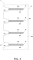
- FIG. 4 is a schematic diagram of the heat exchange part 27 in which a fin 29 is mounted to a flat tube 28 (which will be described later).
- FIG. 5 is a schematic configuration diagram of the outdoor heat exchanger 11. In FIG. 5 , arrows depicted in the heat exchange part 27 each indicate a flow of the refrigerant during the heating operation (in which the outdoor heat exchanger 11 functions as an evaporator).
- orientations and positions are sometimes described using the terms “upper (up)”, “lower (down)”, “left”, “right”, “front (front face)”, and “rear (rear face)”. These orientations and positions are defined by the arrows depicted in FIG. 2 unless otherwise specified. It should be noted that the terms representing the orientations and positions are used for sake of convenience of the description and therefore do not specify the orientation and position of the entire outdoor heat exchanger 11 and the orientation and position of each component of the outdoor heat exchanger 11 unless otherwise specified.
- the outdoor heat exchanger 11 is configured to cause the refrigerant flowing therethrough to exchange heat with air.
- the outdoor heat exchanger 11 mainly includes a distributor 22, a flat tube group 28G that includes the plurality of flat tubes 28, the plurality of fins 29, a liquid header 40, and a gas header 70 (which is an example of a header) (see FIGS. 4 and 5 ).
- the distributor 22, the flat tubes 28, the fins 29, the liquid header 40, and the gas header 70 are each made of aluminum or an aluminum alloy.
- the outdoor heat exchanger 11 includes the heat exchange part 27 placed in a line; therefore, the configuration of the outdoor heat exchanger 11 is different from that in which the flat tubes 28 are arranged in the air flowing direction.
- the outdoor heat exchanger 11 causes the refrigerant flowing through each flat tube 28 to exchange heat with the air flowing through the corresponding air flow path.
- the heat exchange part 27 is divided into a first heat exchange part 27a, a second heat exchange part 27b, a third heat exchange part 27c, a fourth heat exchange part 27d, and a fifth heat exchange part 27e arranged in the up-and-down direction (see FIG. 2 ).
- the distributor 22 is configured to divert the refrigerant.
- the distributor 22 is also configured to merge the diverted refrigerants into one.
- the liquid-refrigerant pipe 20 is connected to the distributor 22.
- the distributor 22 includes a plurality of distributor tubes 22a to 22e.
- the distributor 22 has a function of diverting the refrigerant flowing thereinto through the liquid-refrigerant pipe 20 into the distributor tubes 22a to 22e and leading the diverted refrigerants to spaces defined in the liquid header 40.
- the distributor 22 also has a function of merging the refrigerants flowing thereinto from the liquid header 40 via the distributor tubes 22a to 22e into one and leading the refrigerant toward the liquid-refrigerant pipe 20.
- the flat tube group 28G is an example of a heat transfer tube group.
- the flat tube group 28G includes the plurality of flat tubes 28 (each of which is an example of a heat transfer tube) as a plurality of heat transfer tubes.
- each of the flat tubes 28 is a flat heat transfer tube having upper and lower flat faces 28a each serving as a heat transfer face.
- each of the flat tubes 28 includes a plurality of refrigerant passages 28b through which the refrigerant flows.
- Each of the flat tubes 28 is, for example, a flat porous pipe including a plurality of refrigerant passages 28b each allowing the refrigerant to flow therethrough and having a small passage sectional area.
- the refrigerant passages 28b are arranged in the air flowing direction.
- a maximum width of each of the flat tubes 28 in cross section perpendicular to the refrigerant passages 28b may be 70% or more and alternatively be 85% or more of the outer diameter of the main gas-refrigerant pipe connection portion 19a.
- the flat tubes 28 extend between the liquid header 40 and the gas header 70 in a horizontal direction. Moreover, the flat tubes 28 are arranged up and down in multiple tiers. In this embodiment, the flat tubes 28 between the liquid header 40 and the gas header 70 are bent at two points, so that the heat exchange part 27 including the flat tubes 28 has a substantially "U" shape as seen in plan view (see FIG. 2 ).
- the flat tubes 28 each have a portion that extends in a front-and-rear direction (which is an example of a first direction) and is connected to the gas header 70, and a portion that extends in the front-and-rear direction and is connected to the liquid header 40. In this embodiment, the flat tubes 28 are arranged up and down at certain spacings.
- the fins 29 are used for increasing a heat transfer area of the outdoor heat exchanger 11.
- the fins 29 each have a plate shape extending in a direction in which the flat tubes 28 are arranged in tiers.
- the outdoor heat exchanger 11 is used in the state in which the flat tubes 28 extending in the horizontal direction are arranged in the up-and-down direction. Therefore, the fins 29 extend in the up-and-down direction with the outdoor heat exchanger 11 installed in the outdoor unit 2.
- each of the fins 29 has a plurality of cutouts 29a extending in such a direction that the flat tubes 28 are inserted into the cutouts 29a.
- the cutouts 29a extend in the direction in which the fins 29 extend and in a direction orthogonal to a thickness direction of each fin 29.
- the cutouts 29a in each fin 29 extend in the horizontal direction with the outdoor heat exchanger 11 installed in the outdoor unit 2.
- the cutouts 29a in each fin 29 each have a shape that is almost equal to an outer cross-sectional shape of each flat tube 28. In each fin 29, a spacing between adjacent two of the cutouts 29a corresponds to the spacing between adjacent two of the flat tubes 28.
- the fins 29 are arranged in the direction in which the flat tubes 28 extend.
- the flat tubes 28 are respectively inserted into the cutouts 29a, so that a plurality of air flow paths, through which air flows, are defined between adjacent two of the flat tubes 28.
- Each of the fins 29 has a communicating portion 29b disposed upstream or downstream of the flat tubes 28 in the air flowing direction.
- the communicating portions 29b extend in the up-and-down direction.
- the communicating portions 29b of the fins 29 are located on the windward side with respect to the flat tubes 28.
- the liquid header 40 and the gas header 70 each have a hollow shape.
- the liquid header 40 is connected to a first end of each flat tube 28, and the gas header 70 is connected to a second end of each flat tube 28.
- the outdoor heat exchanger 11 is disposed in the casing (not illustrated) of the outdoor unit 2 such that an axial direction of each of the liquid header 40 and the gas header 70 each having a substantially columnar shape is approximately parallel to a vertical direction.
- the heat exchange part 27 of the outdoor heat exchanger 11 has the "U" shape as seen in plan view.
- the liquid header 40 is disposed near the front left corner of the casing (not illustrated) of the outdoor unit 2 (see FIG. 2 ).
- the gas header 70 is disposed near the front right corner of the casing (not illustrated) of the outdoor unit 2 (see FIG. 2 ).
- the liquid header 40 has a longitudinal direction parallel to the up-and-down direction.
- the liquid header 40 has a liquid-side internal space 23 divided into a plurality of sub-spaces 23a to 23e by a plurality of partition plates 24 (see FIG. 5 ).
- the sub-spaces 23a to 23e are arranged in the up-and-down direction.
- the sub-spaces 23a to 23e of the liquid-side internal space 23 divided by the partition plates 24 are in a non-communicating state in the liquid header 40.
- the distributor tubes 22a to 22e of the distributor 22 are respectively connected to the sub-spaces 23a to 23e.
- the refrigerants then flow through the distributor tubes 22a to 22e.
- the refrigerants are then merged into one at the distributor 22.
- the distributor 22 supplies the diverted refrigerants to the sub-spaces 23a to 23e.
- the gas header 70 has a longitudinal direction parallel to the up-and-down direction (which is an example of a second direction).
- the gas header 70 has a single space.
- the gas header 70 has a gas-side internal space 25 that is not divided by partition plates, unlike the liquid-side internal space 23 divided into the sub-spaces 23a to 23e arranged up and down in the liquid header 40.
- the gas header 70 is connected to a main gas-refrigerant pipe connection portion 19a (which is an example of a first pipe and a gas pipe) and a branch gas-refrigerant pipe connection portion 19b (which is an example of a first pipe and a gas pipe).
- the main gas-refrigerant pipe connection portion 19a and the branch gas-refrigerant pipe connection portion 19b each constitute a gas header 70-side end of the first gas-refrigerant pipe 19 (which is an example of a first pipe and a gas pipe) (see FIG. 5 ).
- the main gas-refrigerant pipe connection portion 19a has an outer diameter that is not limited.
- the outer diameter of the main gas-refrigerant pipe connection portion 19a may be 3 times or more larger and alternatively 5 times or more larger than the outer diameter of the branch gas-refrigerant pipe connection portion 19b.
- the main gas-refrigerant pipe connection portion 19a has a first end connected to the gas header 70 to communicate with the gas-side internal space 25 (which is an example of a space defined by a first wall and a second wall) at an intermediate position of the gas header 70 in a height direction.
- the branch gas-refrigerant pipe connection portion 19b has a first end connected to the gas header 70 to communicate with the gas-side internal space 25 at a position near a lower end of the gas header 70 in the height direction.
- the branch gas-refrigerant pipe connection portion 19b has a second end connected to the main gas-refrigerant pipe connection portion 19a.
- the branch gas-refrigerant pipe connection portion 19b is smaller in inner diameter than the main gas-refrigerant pipe connection portion 19a.
- the branch gas-refrigerant pipe connection portion 19b is connected to the gas header 70 at a position below the main gas-refrigerant pipe connection portion 19a. A refrigerating machine oil retained near the lower end of the gas header 70 is thus drawn into the main gas-refrigerant pipe connection portion 19a.
- the refrigerant in the gas-liquid two-phase state flows into the distributor 22 through the liquid-refrigerant pipe 20.
- the diverted refrigerants then flow through the distributor tubes 22a to 22e and flow into the sub-spaces 23a to 23e of the liquid-side internal space 23 in the liquid header 40.
- the refrigerant flowing through the distributor tube 22a flows into the sub-space 23a
- the refrigerant flowing through the distributor tube 22b flows into the sub-space 23b
- the refrigerant flowing through the distributor tube 22c flows into the sub-space 23c
- the refrigerant flowing through the distributor tube 22d flows into the sub-space 23d
- the refrigerant flowing through the distributor tube 22e flows into the sub-space 23e.
- the refrigerant flows through the refrigerant circuit 6 in the opposite direction to that during the heating operation. Specifically, the high-temperature gas-phase refrigerant flows into the gas-side internal space 25 in the gas header 70 through the main gas-refrigerant pipe connection portion 19a and branch gas-refrigerant pipe connection portion 19b of the first gas-refrigerant pipe 19. The refrigerant is diverted in the gas-side internal space 25 in the gas header 70, and the diverted refrigerants then flow into the flat tubes 28.
- the refrigerants flowed into the flat tubes 28 then flow through the flat tubes 28 and flow into the sub-spaces 23a to 23e of the liquid-side internal space 23 in the liquid header 40.
- the refrigerants flowed into the sub-spaces 23a to 23e of the liquid-side internal space 23 are then merged into one in the distributor 22.
- the merged refrigerant then flows into the liquid-refrigerant pipe 20.
- FIG. 6 is an external view of the gas header 70 to which the main gas-refrigerant pipe connection portion 19a is connected as seen in side view.
- FIG. 7 is a sectional view of the gas header 70 as seen in plan view.
- FIG. 8 is a sectional view of the gas header 70 to which the main gas-refrigerant pipe connection portion 19a and the flat tubes 28 are connected as seen in plan view.
- FIG. 9 is a schematic diagram of a rear side of a first member 71.
- FIG. 10 is a schematic diagram of a rear side of a third member 73.
- FIG. 11 is a schematic diagram of a rear side of a second member 72.
- FIG. 12 is an external perspective view of the second member 72.
- FIG. 13 is a schematic diagram of a rear side of a fourth member 74.
- FIG. 14 is a projection view of a positional relationship among openings in a case where the first member 71 is seen from its rear side.
- the gas header 70 includes the first member 71, the second member 72, the third member 73, the fourth member 74, an upper-end cover member (not illustrated), and a lower-end cover member (not illustrated).
- the first member 71, the second member 72, the third member 73, the fourth member 74, the upper-end cover member, and the lower-end cover member are joined together by brazing.
- the gas header 70 has a substantially quadrangle outer shape as seen in plan view, and one of the four sides is connected to the flat tubes 28.
- the first member 71 mainly forms an outer shape of the gas header 70 in conjunction with the fourth member 74 (to be described later).
- the first member 71 has on its surface a cladding layer containing a brazing material.
- the first member 71 includes a flat tube connection plate 71a, a first outer wall 71b, a second outer wall 71c, a first claw 71d, and a second claw 71e.
- the first member 71 is formed of a sheet metal, which is obtained by rolling, by bending the sheet metal in the longitudinal direction of the gas header 70 although the method of forming the first member 71 is not limited thereto.
- the first member 71 has a uniform thickness that is a first thickness.
- the flat tube connection plate 71a (which is an example of a first portion) has a flat plate shape expanding in the up-and-down direction and in the left-and-right direction.
- the flat tube connection plate 71a has a plurality of flat tube connection openings 71x (each of which is an example of a first opening) arranged in the up-and-down direction.
- Each of the flat tube connection openings 71x is bored through the flat tube connection plate 71a in the thickness direction.
- the flat tubes 28 are inserted into the flat tube connection openings 71x such that the first ends thereof fully pass through the flat tube connection openings 71x, and are joined to the flat tube connection openings 71x by brazing.
- the first thickness which is the thickness of the first member 71 including the flat tube connection plate 71a is relatively thin and is, for example, within a range from about 1.0 mm to about 2.0 mm. This configuration therefore reduces a length of the inner peripheral face of each flat tube connection opening 71x in the thickness direction.
- the first outer wall 71b (which is an example of a wall surface portion) has a planar shape and extends from a front face of a left end of the flat tube connection plate 71a (i.e., the inner side of the outdoor unit 2, the side of the liquid header 40) toward the first gas-refrigerant pipe 19 along the first inner wall 72b (to be described later).
- the second outer wall 71c (which is an example of a wall surface portion) has a planar shape and extends from a front face of a right end of the flat tube connection plate 71a (i.e., the outer side of the outdoor unit 2, the side opposite to the liquid header 40) toward the first gas-refrigerant pipe 19 along the second inner wall 72c (to be described later).
- the first claw 71d (which is an example of a claw) protrudes rightward from a front end of the first outer wall 71b.
- the second claw 71e (which is an example of a claw) protrudes leftward from a front end of the second outer wall 71c.
- the first claw 71d extends on the extension of the first outer wall 71b
- the second claw 71e extends on the extension of the second outer wall 71c.
- the first claw 71d and the second claw 71e are bent to come close to each other.
- the second member 72, the third member 73, and the fourth member 74 are fixed together by crimping with the first member 71.
- the first member 71, the second member 72, the third member 73, and the fourth member 74 are joined together by brazing in, for example, a furnace and are thus completely fixed together.
- the third member 73 has a flat plate shape expanding in the up-and-down direction and the left-and-right direction.
- the third member 73 is stacked on the flat tube connection plate 71a of the first member 71 in contact with a surface of the flat tube connection plate 71a to which the first gas-refrigerant pipe 19 is connected.
- the third member 73 is similar in left-to-right length to the flat tube connection plate 71a of the first member 71 excluding two ends of the flat tube connection plate 71a.
- the third member 73 has on its surface a cladding layer containing a brazing material.
- the third member 73 includes an internal plate 73a and a plurality of internal openings 73x.
- the internal plate 73a has a flat plate shape expanding in the up-and-down direction and the left-and-right direction.
- the internal openings 73x are arranged in the up-and-down direction and are bored through the internal plate 73a in the thickness direction.
- the internal openings 73x in the third member 73 each are larger than the flat tube connection openings 71x in the flat tube connection plate 71a of the first member 71.
- an outer edge of each internal opening 73x in the third member 73 is located outward of an outer edge of the corresponding flat tube connection opening 71x in the flat tube connection plate 71a of the first member 71 in the stacking direction of the members, more specifically in the front-and-rear direction.
- upper and lower portions of the outer edge of each internal opening 73x in the third member 73 may be separated from upper and lower portions of the outer edge of the corresponding flat tube connection opening 71x in the flat tube connection plate 71a by 2 mm or more, preferably 3 mm or more.
- the second member 72 is disposed between the flat tube connection plate 71a of the first member 71 and the main gas-refrigerant pipe connection portion 19a in the front-and-rear direction.
- the second member 72 has a substantially "U" shape as seen in plan view.
- the gas-side internal space 25 described above is defined inside the second member 72, more specifically in the space surrounded by the second member 72, the third member 73, and the ends of the flat tubes 28.
- the second member 72 has a maximum thickness larger than the thickness of the first member 71. This configuration enables pressure resistance strength enhancement to the gas header 70.
- the second member 72 is obtained by extrusion molding in which the longitudinal direction of the gas header 70 is defined as an extruding direction.
- the method of forming the second member 72 is not limited thereto.
- the extrusion molding facilitates formation of portions that are different in thickness from one another. A thick sheet metal is relatively expensive. Therefore, cost reduction is achieved in such a manner that a thick second member 72 is formed by extrusion molding.
- the second member 72 formed by extrusion molding may have no cladding layer containing a brazing material.
- the second member 72 includes a first inner wall 72b, a second inner wall 72c, a coupling portion 72a, a first protrusion 72d, a second protrusion 72e, a first edge 72f, and a second edge 72g.
- the coupling portion 72a opposites to a main gas-refrigerant pipe connection portion 19a-side surface of the third member 73.
- the coupling portion 72a has a plate shape expanding in the up-and-down direction and the left-and-right direction.
- the coupling portion 72a is located on the side of the main gas-refrigerant pipe connection portion 19a in the gas header 70.
- the coupling portion 72a has an internal gas pipe connection opening 72x to which the end of the main gas-refrigerant pipe connection portion 19a is connected.
- the internal gas pipe connection opening 72x is bored through the coupling portion 72a in the thickness direction.
- the coupling portion 72a has an opening (not illustrated) to which the end of the branch gas-refrigerant pipe connection portion 19b is connected. This opening is bored through the coupling portion 72a in the thickness direction.
- the first inner wall 72b (which is an example of a first wall) has a planar shape extending from the left end of the coupling portion 72a (i.e., the inner side of the outdoor unit 2, the side closer to the liquid header 40) toward the rear side from which the flat tubes 28 protrude.
- the first inner wall 72b has a left face that is in surface contact with a right face of the first outer wall 71b of the first member 71.
- the second inner wall 72c (which is an example of a second wall) has a planar shape extending from the right end of the coupling portion 72a (i.e., the outer side of the outdoor unit 2, the side opposite to the liquid header 40) toward the rear side from which the flat tubes 28 protrude.
- the second inner wall 72c has a right face that is in surface contact with a left face of the second outer wall 71c of the first member 71.
- the first inner wall 72b opposites to the second inner wall 72c.
- a front end of the first inner wall 72b particularly opposites to a front end of the second inner wall 72c.
- the coupling portion 72a, the first inner wall 72b, and the second inner wall 72c each have a thickness larger than the thickness of the first member 71 which may be 1.5 times or more, preferably twice or more larger than the thickness of the first member 71.
- the first inner wall 72b and the second inner wall 72c each may have a length in the protruding direction of the flat tubes 28 (the front-and-rear direction), 3 times or more, preferably 5 times or more larger than a length of the coupling portion 72a in the protruding direction of the flat tubes 28 (the front-and-rear direction).
- these lengths are not limited thereto.
- the coupling portion 72a couples the first inner wall 72b to the second inner wall 72c. Specifically, the coupling portion 72a couples the front end (the main gas-refrigerant pipe connection portion 19a-side end) of the first inner wall 72b to the front end (the main gas-refrigerant pipe connection portion 19a-side end) of the second inner wall 72c.
- the coupling portion 72a extends in the left-and-right direction when the gas header 70 is seen in plan view.
- the left-and-right direction is an example of a third direction.
- the third direction is orthogonal to both the first direction and the second direction. More preferably, the first direction, the second direction, and the third direction are orthogonal to one another.
- the first edge 72f is located behind the first inner wall 72b. That is, the first edge 72f is located closer to the flat tubes 28 than the first inner wall 72b is.
- the first edge 72f has a left face that is flush with a left face of the first inner wall 72b and is in surface contact with a right face of the first outer wall 71b of the first member 71.
- the first edge 72f has a rear end that is in contact with a front face of the third member 73.
- the first edge 72f is smaller in thickness (width in the left-and-right direction) than the first inner wall 72b.
- a contact portion between the first edge 72f and the front face of the third member 73 is located leftward of the flat tubes 28 and leftward of left ends of the internal openings 73x (each of which is an example of a second opening) in the third member 73.
- the second edge 72g is located behind the second inner wall 72c. That is, the second edge 72g is located closer to the flat tubes 28 than the second inner wall 72c is.
- the second edge 72g has a right face that is flush with a right face of the second inner wall 72c and is in surface contact with a left face of the second outer wall 71c of the first member 71.
- the second edge 72g has a rear end that is in contact with the front face of the third member 73.
- the second edge 72g is smaller in thickness (width in the left-and-right direction) than the second inner wall 72c.
- a contact portion between the second edge 72g and the front face of the third member 73 is located rightward of the flat tubes 28 and rightward of right ends of the internal openings 73x in the third member 73.
- a length between the first edge 72f and the second edge 72g is larger than a width of each flat tube 28, larger than a width of each flat tube connection opening 71x in the first member 71, and larger than a width of each internal opening 73x in the third member 73.
- the first edge 72f and the second edge 72g each extend from the upper end to the lower end of the gas header 70.
- the first protrusion 72d protrudes rightward (toward the second inner wall 72c) from the rear end of the first inner wall 72b, that is, a portion forward of the first edge 72f.
- the first protrusion 72d extends from the upper end to the lower end of the gas header 70.
- the first protrusion 72d has a right end that is located rightward of the left ends of the internal openings 73x in the third member 73 and rightward of the left ends of the flat tubes 28.
- the first protrusion 72d is located closer to the flat tubes 28 with respect to a center of the second member 72 in the front-and-rear direction.
- the second protrusion 72e protrudes leftward (toward the first inner wall 72b) from the rear end of the second inner wall 72c, that is, a portion forward of the second edge 72g.
- the second protrusion 72e extends from the upper end to the lower end of the gas header 70.
- the second protrusion 72e has a left end located leftward of the right ends of the internal openings 73x in the third member 73 and leftward of the right ends of the flat tubes 28.
- the second protrusion 72e is located closer to the flat tubes 28 with respect to the center of the second member 72 in the front-and-rear direction.
- a minimum distance between the first protrusion 72d and the second protrusion 72e (a distance between the first protrusion 72d and the second protrusion 72e in the left-and-right direction) is shorter than a maximum width of each flat tube 28 in section perpendicular to the refrigerant passage 28b.
- the fourth member 74 has a flat plate shape expanding in the up-and-down direction and the left-and-right direction.
- the fourth member 74 is stacked on the second member 72 in contact with a front face of the coupling portion 72a.
- the fourth member 74 is similar in left-to-right length to the third member 73.
- the fourth member 74 is also similar in left-to-right length to the flat tube connection plate 71a of the first member 71 excluding the two ends of the flat tube connection plate 71a.
- the fourth member 74 has on its surface a cladding layer containing a brazing material.
- the fourth member 74 is a plate-shaped member; therefore, the cladding layer containing the brazing material is formed on the surface of the fourth member 74 with ease. Therefore, for example, as in the case where the second member 72 is formed by extrusion molding, even in a case where the second member 72 has no cladding layer containing a brazing material, the second member 72 is joined to the other members by brazing with the brazing material on the fourth member 74.
- the fourth member 74 includes an external plate 74a and has an external gas pipe connection opening 74x.
- the external plate 74a has a flat plate shape expanding in the up-and-down direction and the left-and-right direction.
- the external gas pipe connection opening 74x is bored through the external plate 74a in the thickness direction, and the end of the main gas-refrigerant pipe connection portion 19a is connected to the external gas pipe connection opening 74x.
- the external plate 74a has in its lower side an opening (not illustrated) to which the end of the branch gas-refrigerant pipe connection portion 19b is connected. This opening is bored through the external plate 74a in the thickness direction.
- the main gas-refrigerant pipe connection portion 19a and the branch gas-refrigerant pipe connection portion 19b thus communicate with an inner face of the flat tube connection plate 71a of the first member 71 via the gas-side internal space 25 defined by the external gas pipe connection opening 74x, the internal gas pipe connection opening 72x, the first inner wall 72b, and the second inner wall 72c.
- the fourth member 74 has a front face that is crimped in contact with the first claw 71d and second claw 71e of the first member 71.
- the first inner wall 72b of the second member 72 extends rearward (in the protruding direction of the flat tubes 28) from the left end of the coupling portion 72a, and the second inner wall 72c of the second member 72 extends rearward from the right end of the coupling portion 72a.
- the space in the header can also be widened in such a manner that multiple plate-shaped members each having an opening are stacked on top of each other. This case however results in an increase in parts count.
- the space in the header can also be secured wide in such a manner that openings are bored by punching or the like in a thick plate-shaped member. This case however makes it difficult to perform punching because of the thick plate-shaped member.
- the second member 72 of the gas header 70 according to this embodiment is a single member formed by extrusion molding. This configuration therefore reduces a parts count for securing the gas-side internal space 25 wide, without a problem accompanied with the punching or the like.
- first inner wall 72b and the second inner wall 72c extend in the protruding direction of the flat tubes 28 in order to secure the gas-side internal space 25 wide.
- first inner wall 72b and the second inner wall 72c are coupled together by the coupling portion 72a, and the coupling portion 72a, the first inner wall 72b, and the second inner wall 72c are integrated. This configuration enables strength enhancement to the second member 72 and enables pressure resistance strength enhancement to the gas header 70.
- the coupling portion 72a is particularly provided for coupling the front end of the first inner wall 72b to the front end of the second inner wall 72c. This case secures the gas-side internal space 25 wide with ease as compared with a case where the coupling portion 72a couples any portion of the first inner wall 72b in the front-and-rear direction, excluding the two ends of the first inner wall 72b in the front-and-rear direction, to any portion of the second inner wall 72c in the front-and-rear direction, excluding the two ends of the second inner wall 72c in the front-and-rear direction.
- the flat tube connection plate 71a of the first member 71 and the third member 73 each have a plate shape.
- the flat tubes 28 are inserted perpendicularly to the flat tube connection plate 71a of the first member 71 and the third member 73.
- the first outer wall 71b and the second outer wall 71c extend perpendicularly from the left and right ends of the flat tube connection plate 71a of the first member 71, respectively.
- the first inner wall 72b and the second inner wall 72c of the second member 72 are joined perpendicularly to the left and right ends of the third member 73, respectively.
- the first member 71 including the flat tube connection plate 71a is relatively thin. In inserting each flat tube 28 into the corresponding flat tube connection opening 71x before joining the flat tube 28 and the flat tube connection opening 71x together by brazing, this configuration reduces friction between the inner peripheral face of the flat tube connection opening 71x and the outer peripheral face of the flat tube 28, which facilitates the inserting work.
- the third member 73 is stacked on the flat tube connection plate 71a in the thickness direction. This configuration enables pressure resistance strength enhancement to the portion of the gas header 70 on the side to which the flat tubes 28 are connected.
- each internal opening 73x in the third member 73 is located outward of the outer edge of the corresponding flat tube connection opening 71x in the flat tube connection plate 71a of the first member 71.
- the overflowing brazing material flows into the spaces in the internal openings 73x in the third member 73, the spaces being located outside the flat tubes 28. This configuration therefore suppresses occurrence of a situation in which the refrigerant passages 28b in the flat tubes 28 are filled with the brazing material.
- the minimum distance between the first protrusion 72d and the second protrusion 72e (a distance between the first protrusion 72d and the second protrusion 72e in the left-and-right direction) of the second member 72 is shorter than the maximum width of each flat tube 28 in section perpendicular to the refrigerant passage 28b. This configuration therefore defines the degree of insertion of each flat tube 28 in the gas header 70.
- the first protrusion 72d and the second protrusion 72e that define the degree of insertion of each flat tube 28 are located closer to the flat tubes 28 with respect to the center of the second member 72 in the front-and-rear direction. This configuration therefore secures the gas-side internal space 25 sufficiently wide.
- the coupling portion 72a couples the end of the first inner wall 72b to the end of the second inner wall 72c.
- FIGS. 15 and 16 may be used as a second member of the gas header 70 of the outdoor heat exchanger 11.
- FIG. 15 is a sectional view of the gas header 70 to which the main gas-refrigerant pipe connection portion 19a and the flat tubes 28 are connected as seen in plan view.
- FIG. 16 is a projection view of a positional relationship among openings in a case where the second member 172 is seen from its rear side.
- the second member 172 includes a coupling portion 172a instead of the coupling portion 72a of the second member 72 according to the foregoing embodiment.
- the coupling portion 172a couples a portion between the ends of the first inner wall 72b in the front-and-rear direction (the protruding direction of the flat tubes 28) to a portion between the ends of the second inner wall 72c in the front-and-rear direction (the protruding direction of the flat tubes 28).
- the coupling portion 172a couples the first inner wall 72b and the second inner wall 72c at the portions different from the ends. This configuration therefore enables structural strength enhancement to the second member 172.
- the coupling portion 172a has a plate shape expanding in the up-and-down direction and the left-and-right direction.
- the coupling portion 172a has a plurality of internal gas pipe connection openings 172x arranged in the up-and-down direction.
- the internal gas pipe connection openings 172x are formed corresponding to the respective flat tubes 28.
- the internal gas pipe connection openings 172x are larger in size in the up-and-down direction than the flat tubes 28 and the flat tube connection openings 71x in the first member 71.
- the internal gas pipe connection openings 172x are smaller in size in the width direction (the left-and-right direction) than the flat tubes 28 and the flat tube connection openings 71x in the first member 71.
- each flat tube 28 This configuration thus defines the degree of insertion of each flat tube 28. Since an edge of each internal gas pipe connection opening 172x is used for defining the degree of insertion of the corresponding flat tube 28, the second member 72 does not necessarily include the first protrusion 72d and the second protrusion 72e in the foregoing embodiment.
- the gas header 70 includes the third member 73 and the fourth member 74.
- a gas header 70 illustrated in FIG. 17 may not include one of or both the third member 73 and the fourth member 74 in the foregoing embodiment.
- Patent Literature 1 WO 2015/004719 A1
Abstract
Description
- The present disclosure relates to a heat exchanger and a heat pump apparatus.
- A known refrigerant cycle apparatus such as an air conditioning apparatus includes a heat exchanger including a heat transfer tube through which a refrigerant flows and a header to which the heat transfer tube is connected.
- For example, Patent Literature 1 (
WO 2015/004719 A1 ) discloses a heat exchanger including a gas header that includes a plurality of plate-shaped members stacked on top of each other, the plate-shaped members each having an opening. - It is necessary to increase the number of plate-shaped members in order to secure a wide space in the header that includes the plurality of plate-shaped members stacked on top of each other, the plate-shaped members each having the opening.
- The present disclosure provides a heat exchanger including a header that enables a reduction in parts count even when a large space is secured in the header, and also provides a heat pump apparatus.
- A first aspect provides a heat exchanger connected to a first pipe through which a refrigerant flows. The heat exchanger includes a plurality of heat transfer tubes, and a header connected to the heat transfer tubes. The header includes a first member and a second member. The first member includes a first portion connected to the heat transfer tubes. The second member is disposed between the first pipe and the first portion. The second member includes a first wall, a second wall, and a coupling portion. The first wall and the second wall each extend in a first direction in which the heat transfer tubes extend. The coupling portion couples the first wall to the second wall. The first pipe communicates with each heat transfer tube through a space defined by the first wall and the second wall.
- In the heat exchanger, the first and second walls of the second member extend in the first direction in which the heat transfer tubes extend. With this configuration, the second member secures the space defined by the first wall and the second wall.
- A second aspect provides the heat exchanger according to the first aspect, in which the coupling portion couples an end of the first wall in the first direction to an end of the second wall in the first direction.
- It is sufficient for the coupling portion to couple the end of the first wall in the first direction to the end of the second wall in the first direction. For example, the coupling portion may couple the first wall to the second wall on the opposite side to the heat transfer tubes in the first direction.
- In the heat exchanger, the coupling portion couples the end of the first wall to the end of the second wall. This configuration therefore secures the space defined by the first wall and the second wall wide with ease.
- A third aspect provides the heat exchanger according to the first aspect, in which the coupling portion couples a portion of the first wall, the portion being different from two ends of the first wall in the first direction, to a portion of the second wall, the portion being different from two ends of the second wall in the first direction.
- The heat exchanger enables strength enhancement to the second member since the coupling portion couples a portion of the first wall in the first direction, the portion being different from two ends of the first wall in the first direction, to a portion of the second wall in the first direction, the portion being different from two ends of the second wall in the first direction.
- A fourth aspect provides the heat exchanger according to any of the first to third aspects, in which the first portion has a plate shape.
- Preferably, the first member has a plate shape expanding perpendicularly to a direction in which the heat transfer tubes extend.
- The heat exchanger suppresses occurrence of a situation in which an unnecessary space is defined around a portion of each heat transfer tube in the header, since the heat transfer tubes are connected to the plate-shaped first portion.
- A fifth aspect provides the heat exchanger according to any of the first to fourth aspects, in which the second member includes a first protrusion and a second protrusion. The first protrusion protrudes from the first wall toward the second wall. The first protrusion is located closer to the heat transfer tubes than the coupling portion is. The second protrusion protrudes from the second wall toward the first wall. The second protrusion is located closer to the heat transfer tubes than the coupling portion is. A minimum distance between the first protrusion and the second protrusion is shorter than a maximum width of each heat transfer tube in section.
- According to the heat exchanger, the first and second protrusions of the second member define a degree of insertion of the heat transfer tubes into the header.
- A sixth aspect provides the heat exchanger according to the fifth aspect, in which the coupling portion couples a portion of the first wall, the portion being located closer to the first pipe with respect to a center of the first wall in the first direction, to a portion of the second wall, the portion being located closer to the first pipe with respect to a center of the second wall in the first direction. The first protrusion is located closer to the heat transfer tubes with respect to the center of the first wall in the first direction. The second protrusion is located closer to the heat transfer tubes with respect to the center of the second wall in the first direction.
- The heat exchanger ensures a wide space defined by the ends of the heat transfer tubes, the coupling portion, the first wall, and the second wall.
- A seventh aspect provides the heat exchanger according to any of the first to sixth aspects, further including a third member. The third member is disposed so as to face a side, where the second member is disposed, of the first portion of the first member. The first portion has a plurality of first openings into which the heat transfer tubes are inserted. The third member has a plurality of second openings into which the heat transfer tubes are inserted. Each first opening has a portion overlapping the respective second opening as seen in the first direction.
- According to the heat exchanger, the heat transfer tubes are fixed with the heat transfer tubes inserted into the first openings in the first portion. Since the first portion overlaps the third member, a thickness of an overlapping portion of the first portion and the third member is secured, which enhances strength. This configuration thus secures the strength of the overlapping portion of the first portion and the third member even in a case where the first portion is formed thin for reducing friction between an outer peripheral face of each heat transfer tube and the corresponding first opening, the friction being caused in inserting the heat transfer tubes into the first openings.
- An eighth aspect provides the heat exchanger according to the seventh aspect, in which each second opening of the third member is larger than the corresponding first opening of the first portion as seen in the first direction. An edge of each second opening of the third member is located outward of an edge of corresponding first opening of the first portion as seen in the first direction.
- According to the heat exchanger, in joining the first portion to the third member by brazing, an excessive brazing material is moved to a region in each second opening, the region being located outside the heat transfer tubes. This configuration therefore suppresses occurrence of a situation in which the flow paths in the heat transfer tubes are filled with the brazing material.
- A ninth aspect provides the heat exchanger according to any of the first to eighth aspects, further including a fourth member to which the first pipe is connected. The first member includes wall surface portions and claws. The wall surface portions respectively extend from two ends of the first portion toward the first pipe respectively along the first wall and the second wall. The claws are disposed on ends of the wall surface portions opposite to the first portion. The claws extend to come close to each other. The claws are in contact with a surface of the fourth member opposite to the first portion.
- It should be noted that the two ends of the first portion may be two ends of the first portion as seen in a longitudinal direction of the first portion.
- According to the heat exchanger, the fourth member is held by the claws of the first member. The second member is thus surrounded by the first member and the fourth member.
- In a case where each of the first member and the fourth member is made of pitting metal, the corrosion resistance around the header is improved.
- A tenth aspect provides the heat exchanger according to any of the first to ninth aspects, in which each heat transfer tube is a flat tube. Each flat tube has a flat face.
- Preferably, the flat tubes each have such a sectional shape that a width of the first portion in the longitudinal direction is shorter than a width of the first portion in a direction perpendicular to the longitudinal direction.
- An eleventh aspect provides the heat exchanger according to any of the first to tenth aspects, in which the first pipe is a gas pipe.
- It should be noted that the refrigerant flowing through the gas pipe is not limited to a refrigerant in a gas state, but may be a refrigerant in a gas-liquid two-phase state. Such a refrigerant in a gas-liquid two-phase state preferably has a degree of dryness that is not less than 0.8, for example.
- The heat exchanger enables pressure resistance strength enhancement to the header connected to a gas pipe, with ease.
- A twelfth aspect provides a heat pump apparatus including the heat exchanger according to any of the first to eleventh aspects.
-
-
FIG. 1 is a schematic configuration diagram of an air conditioning apparatus. -
FIG. 2 is a schematic perspective view of an outdoor heat exchanger. -
FIG. 3 is a partially enlarged view of a heat exchange part of the outdoor heat exchanger. -
FIG. 4 is a schematic diagram of the heat exchange part in which a heat transfer fin is mounted to a flat tube. -
FIG. 5 is a diagram of a flow of a refrigerant in the outdoor heat exchanger functioning as an evaporator for the refrigerant. -
FIG. 6 is an external view of a gas header to which a main gas-refrigerant pipe connection portion is connected as seen in side view. -
FIG. 7 is a sectional view of the gas header as seen in plan view. -
FIG. 8 is a sectional view of the gas header to which the main gas-refrigerant pipe connection portion and the flat tube are connected as seen in plan view. -
FIG. 9 is a schematic diagram of a rear side of a first member. -
FIG. 10 is a schematic diagram of a rear side of a third member. -
FIG. 11 is a schematic diagram of a rear side of a second member. -
FIG. 12 is an external perspective view of the second member. -
FIG. 13 is a schematic diagram of a rear side of a fourth member. -
FIG. 14 is a projection view of a positional relationship among openings in a case where the first member is seen from its rear side. -
FIG. 15 is a sectional view of a gas header to which a main gas-refrigerant pipe connection portion and a flat tube are connected as seen in plan view in Modification A. -
FIG. 16 is a projection view of a positional relationship among openings in a case where a second member is seen from its rear side in Modification A. -
FIG. 17 is a sectional view of a gas header as seen in plan view in Modification B. - A description will be given of an air conditioning apparatus including a heat exchanger to which the present disclosure is applied in accordance with an embodiment.
- A description will be given of an air conditioning apparatus 1 with reference to the drawings.
-
FIG. 1 is a schematic configuration diagram of the air conditioning apparatus 1 including anoutdoor heat exchanger 11 corresponding to a heat exchanger according to an embodiment of the present disclosure. - The air conditioning apparatus 1 (which is an example of a heat pump apparatus) is configured to perform a vapor compression refrigeration cycle, thereby cooling and heating an air conditioning target space. Examples of the air conditioning target space may include, but not limited to, spaces in buildings such as an office building, a commercial facility, and a residence. It should be noted that the air conditioning apparatus is merely an example of a refrigerant cycle apparatus. The heat exchanger according to the present disclosure may be used for other refrigerant cycle apparatuses such as a refrigerator, a freezer, a water heater, and an underfloor heating apparatus.
- As illustrated in
FIG. 1 , the air conditioning apparatus 1 mainly includes anoutdoor unit 2, anindoor unit 9, a liquid-refrigerant connection pipe 4, a gas-refrigerant connection pipe 5, and acontrol unit 3 configured to control components of theoutdoor unit 2 and components of theindoor unit 9. The liquid-refrigerant connection pipe 4 and the gas-refrigerant connection pipe 5 connect theoutdoor unit 2 to theindoor unit 9. In the air conditioning apparatus 1, theoutdoor unit 2 and theindoor unit 9 are connected via the liquid-refrigerant connection pipe 4 and the gas-refrigerant connection pipe 5 to constitute arefrigerant circuit 6. - The air conditioning apparatus 1 illustrated in
FIG. 1 includes oneindoor unit 9. The air conditioning apparatus 1 may include a plurality ofindoor units 9 connected in parallel to theoutdoor unit 2 via the liquid-refrigerant connection pipe 4 and the gas-refrigerant connection pipe 5. The air conditioning apparatus 1 may alternatively include a plurality ofoutdoor units 2. The air conditioning apparatus 1 may alternatively include anoutdoor unit 2 and anindoor unit 9 that are integrated with each other. - The
outdoor unit 2 is installed outside the air conditioning target space. For example, theoutdoor unit 2 is installed on the rooftop of a building or near a wall surface of a building. - The
outdoor unit 2 mainly includes an accumulator 7, acompressor 8, a four-way switching valve 10, theoutdoor heat exchanger 11, anexpansion mechanism 12, a liquid-side shutoff valve 13, a gas-side shutoff valve 14, and an outdoor fan 16 (seeFIG. 1 ). - The
outdoor unit 2 mainly includes, as refrigerant pipes for connecting various components of therefrigerant circuit 6, asuction pipe 17, adischarge pipe 18, a first gas-refrigerant pipe 19, a liquid-refrigerant pipe 20, and a second gas-refrigerant pipe 21 (seeFIG. 1 ). Thesuction pipe 17 connects the four-way switching valve 10 and a suction side of thecompressor 8. Thesuction pipe 17 is provided with the accumulator 7. Thedischarge pipe 18 connects a discharge side of thecompressor 8 and the four-way switching valve 10. The first gas-refrigerant pipe 19 connects the four-way switching valve 10 and a gas side of theoutdoor heat exchanger 11. The liquid-refrigerant pipe 20 connects a liquid side of theoutdoor heat exchanger 11 and the liquid-side shutoff valve 13. The liquid-refrigerant pipe 20 is provided with theexpansion mechanism 12. The second gas-refrigerant pipe 21 connects the four-way switching valve 10 and the gas-side shutoff valve 14. - The
compressor 8 is configured to suck in a low-pressure refrigerant in the refrigeration cycle, through thesuction pipe 17, compress the refrigerant in a compression mechanism (not illustrated), and discharge the compressed refrigerant to thedischarge pipe 18. - The four-
way switching valve 10 is configured to switch a refrigerant flowing direction, thereby changing a state of therefrigerant circuit 6 between a cooling operation state and a heating operation state. When therefrigerant circuit 6 is in the cooling operation state, theoutdoor heat exchanger 11 functions as a radiator (a condenser) for the refrigerant, and anindoor heat exchanger 91 functions as an evaporator for the refrigerant. When therefrigerant circuit 6 is in the heating operation state, theoutdoor heat exchanger 11 functions as an evaporator for the refrigerant, and theindoor heat exchanger 91 functions as a condenser for the refrigerant. When the four-way switching valve 10 switches the state of therefrigerant circuit 6 to the cooling operation state, the four-way switching valve 10 causes thesuction pipe 17 to communicate with the second gas-refrigerant pipe 21, and causes thedischarge pipe 18 to communicate with the first gas-refrigerant pipe 19 (see a solid line in the four-way switching valve 10 illustrated inFIG. 1 ). When the four-way switching valve 10 switches the state of therefrigerant circuit 6 to the heating operation state, the four-way switching valve 10 causes thesuction pipe 17 to communicate with the first gas-refrigerant pipe 19, and causes thedischarge pipe 18 to communicate with the second gas-refrigerant pipe 21 (see a broken line in the four-way switching valve 10 illustrated inFIG. 1 ). - The outdoor heat exchanger 11 (which is an example of a heat exchanger) is configured to cause the refrigerant flowing therethrough to exchange heat with air (heat source air) in the place where the
outdoor unit 2 is installed. A specific description on theoutdoor heat exchanger 11 will be given later. - The
expansion mechanism 12 is disposed between theoutdoor heat exchanger 11 and theindoor heat exchanger 91 in therefrigerant circuit 6. In this embodiment, theexpansion mechanism 12 is disposed on the liquid-refrigerant pipe 20 between theoutdoor heat exchanger 11 and the liquid-side shutoff valve 13. In the air conditioning apparatus 1, theoutdoor unit 2 includes theexpansion mechanism 12. Alternatively, the indoor unit 9 (to be described later) may include theexpansion mechanism 12. Theexpansion mechanism 12 is configured to adjust a pressure and a flow rate of the refrigerant flowing through the liquid-refrigerant pipe 20. In this embodiment, theexpansion mechanism 12 is an opening degree-changeable electronic expansion valve. Theexpansion mechanism 12 may alternatively be a feeler bulb-type expansion valve or a capillary tube. - The accumulator 7 has a gas-liquid separating function of separating the refrigerant, which flows thereinto, into the gas refrigerant and the liquid refrigerant. The accumulator 7 also has a surplus refrigerant storing function of storing a surplus of the refrigerant in accordance with, for example, a variation in operation load.
- The liquid-
side shutoff valve 13 is disposed on a joint between the liquid-refrigerant pipe 20 and the liquid-refrigerant connection pipe 4. The gas-side shutoff valve 14 is disposed on a joint between the second gas-refrigerant pipe 21 and the gas-refrigerant connection pipe 5. The liquid-side shutoff valve 13 and the gas-side shutoff valve 14 are open during the operation of the air conditioning apparatus 1. - The
outdoor fan 16 is configured to take heat source air from the outside in a casing (not illustrated) of theoutdoor unit 2, supply the heat source air to theoutdoor heat exchanger 11, and discharge the air subjected to heat exchange with the refrigerant in theoutdoor heat exchanger 11, to the outside of the casing of theoutdoor unit 2. Theoutdoor fan 16 is, for example, a propeller fan. - The
indoor unit 9 is installed in the air conditioning target space. For example, theindoor unit 9 is designed to be embedded in a ceiling. Theindoor unit 9 may alternatively be designed to be suspended from a ceiling, hung on a wall, or placed on a floor. Alternatively, theindoor unit 9 may be installed outside the air conditioning target space. For example, theindoor unit 9 may be installed in an attic, a machine chamber, a garage, or the like. In this case, an air passage is provided for supplying air subjected to heat exchange with the refrigerant in theindoor heat exchanger 91, from theindoor unit 9 to the air conditioning target space. The air passage is, for example, a duct. - The
indoor unit 9 mainly includes theindoor heat exchanger 91 and an indoor fan 92 (seeFIG. 1 ). - The
indoor heat exchanger 91 causes the refrigerant flowing therethrough to exchange heat with the air in the air conditioning target space. Theindoor heat exchanger 91 may be of any type. For example, theindoor heat exchanger 91 may be a fin-and-tube heat exchanger that includes a plurality of heat transfer tubes and a plurality of fins (not illustrated). Theindoor heat exchanger 91 has a first end connected to the liquid-refrigerant connection pipe 4 via a refrigerant pipe. Theindoor heat exchanger 91 has a second end connected to the gas-refrigerant connection pipe 5 via a refrigerant pipe. - The
indoor fan 92 is configured to suck air in the air conditioning target space into a casing (not illustrated) of theindoor unit 9, supply the air to theindoor heat exchanger 91, and blow out the air subjected to heat exchange with the refrigerant in theindoor heat exchanger 91 toward the air conditioning target space. Theindoor fan 92 is, for example, a turbo fan. Theindoor fan 92 is not limited to a turbo fan, and a fan of any type may be appropriately selected as theindoor fan 92. - The
control unit 3 is a functional unit configured to control the operations of the various components of the air conditioning apparatus 1. - For example, the
control unit 3 includes an outdoor control unit (not illustrated) of theoutdoor unit 2 and an indoor control unit (not illustrated) of theindoor unit 9 that are connected to communicate with each other via a transmission line (not illustrated). Each of the outdoor control unit and the indoor control unit includes, for example, a microcomputer and a memory storing various programs for controlling the air conditioning apparatus 1, the programs being executable by the microcomputer. For sake of convenience,FIG. 1 depicts thecontrol unit 3 at a position away from theoutdoor unit 2 and theindoor unit 9. - The functions of the
control unit 3 are not necessarily achieved by the cooperation of the outdoor control unit and the indoor control unit. For example, the functions of thecontrol unit 3 may be achieved by one of the outdoor control unit and the indoor control unit. Alternatively, some of or all the functions of thecontrol unit 3 may be achieved by a control device (not illustrated) different from the outdoor control unit and the indoor control unit. - As illustrated in
FIG. 1 , thecontrol unit 3 is electrically connected to various components (including thecompressor 8, the four-way switching valve 10, theexpansion mechanism 12, theoutdoor fan 16, and the indoor fan 92) of theoutdoor unit 2 andindoor unit 9. Thecontrol unit 3 is also electrically connected to various sensors (not illustrated) in theoutdoor unit 2 andindoor unit 9. Thecontrol unit 3 is capable of communicating with a remote controller (not illustrated) to be operated by a user of the air conditioning apparatus 1. - The
control unit 3 starts or stops an operation of the air conditioning apparatus 1 and controls the operations of the various components of the air conditioning apparatus 1, based on, for example, measurement signals from the various sensors and commands from the remote controller (not illustrated). - Next, a description will be given of a configuration of the
outdoor heat exchanger 11 with reference to the drawings. -
FIG. 2 is a schematic perspective view of theoutdoor heat exchanger 11.FIG. 3 is a partially enlarged view of a heat exchange part 27 (to be described later) of theoutdoor heat exchanger 11.FIG. 4 is a schematic diagram of theheat exchange part 27 in which afin 29 is mounted to a flat tube 28 (which will be described later).FIG. 5 is a schematic configuration diagram of theoutdoor heat exchanger 11. InFIG. 5 , arrows depicted in theheat exchange part 27 each indicate a flow of the refrigerant during the heating operation (in which theoutdoor heat exchanger 11 functions as an evaporator). - In the following, orientations and positions are sometimes described using the terms "upper (up)", "lower (down)", "left", "right", "front (front face)", and "rear (rear face)". These orientations and positions are defined by the arrows depicted in
FIG. 2 unless otherwise specified. It should be noted that the terms representing the orientations and positions are used for sake of convenience of the description and therefore do not specify the orientation and position of the entireoutdoor heat exchanger 11 and the orientation and position of each component of theoutdoor heat exchanger 11 unless otherwise specified. - The
outdoor heat exchanger 11 is configured to cause the refrigerant flowing therethrough to exchange heat with air. - The
outdoor heat exchanger 11 mainly includes adistributor 22, aflat tube group 28G that includes the plurality offlat tubes 28, the plurality offins 29, aliquid header 40, and a gas header 70 (which is an example of a header) (seeFIGS. 4 and5 ). In this embodiment, thedistributor 22, theflat tubes 28, thefins 29, theliquid header 40, and thegas header 70 are each made of aluminum or an aluminum alloy. - As will be described later, the
flat tubes 28 and thefins 29 fixed to theflat tubes 28 constitute the heat exchange part 27 (seeFIGS. 2 and3 ). Theoutdoor heat exchanger 11 includes theheat exchange part 27 placed in a line; therefore, the configuration of theoutdoor heat exchanger 11 is different from that in which theflat tubes 28 are arranged in the air flowing direction. In theoutdoor heat exchanger 11, air flows through an air flow path defined by eachflat tube 28 and the correspondingfin 29 in theheat exchange part 27. Theoutdoor heat exchanger 11 causes the refrigerant flowing through eachflat tube 28 to exchange heat with the air flowing through the corresponding air flow path. Theheat exchange part 27 is divided into a firstheat exchange part 27a, a secondheat exchange part 27b, a thirdheat exchange part 27c, a fourthheat exchange part 27d, and a fifthheat exchange part 27e arranged in the up-and-down direction (seeFIG. 2 ). - The
distributor 22 is configured to divert the refrigerant. Thedistributor 22 is also configured to merge the diverted refrigerants into one. The liquid-refrigerant pipe 20 is connected to thedistributor 22. Thedistributor 22 includes a plurality ofdistributor tubes 22a to 22e. Thedistributor 22 has a function of diverting the refrigerant flowing thereinto through the liquid-refrigerant pipe 20 into thedistributor tubes 22a to 22e and leading the diverted refrigerants to spaces defined in theliquid header 40. Thedistributor 22 also has a function of merging the refrigerants flowing thereinto from theliquid header 40 via thedistributor tubes 22a to 22e into one and leading the refrigerant toward the liquid-refrigerant pipe 20. - The
flat tube group 28G is an example of a heat transfer tube group. Theflat tube group 28G includes the plurality of flat tubes 28 (each of which is an example of a heat transfer tube) as a plurality of heat transfer tubes. As illustrated inFIG. 3 , each of theflat tubes 28 is a flat heat transfer tube having upper and lower flat faces 28a each serving as a heat transfer face. As illustrated inFIG. 3 , each of theflat tubes 28 includes a plurality ofrefrigerant passages 28b through which the refrigerant flows. Each of theflat tubes 28 is, for example, a flat porous pipe including a plurality ofrefrigerant passages 28b each allowing the refrigerant to flow therethrough and having a small passage sectional area. In this embodiment, therefrigerant passages 28b are arranged in the air flowing direction. A maximum width of each of theflat tubes 28 in cross section perpendicular to therefrigerant passages 28b may be 70% or more and alternatively be 85% or more of the outer diameter of the main gas-refrigerantpipe connection portion 19a. - As illustrated in
FIG. 5 , in theoutdoor heat exchanger 11, theflat tubes 28 extend between theliquid header 40 and thegas header 70 in a horizontal direction. Moreover, theflat tubes 28 are arranged up and down in multiple tiers. In this embodiment, theflat tubes 28 between theliquid header 40 and thegas header 70 are bent at two points, so that theheat exchange part 27 including theflat tubes 28 has a substantially "U" shape as seen in plan view (seeFIG. 2 ). Theflat tubes 28 each have a portion that extends in a front-and-rear direction (which is an example of a first direction) and is connected to thegas header 70, and a portion that extends in the front-and-rear direction and is connected to theliquid header 40. In this embodiment, theflat tubes 28 are arranged up and down at certain spacings. - The
fins 29 are used for increasing a heat transfer area of theoutdoor heat exchanger 11. Thefins 29 each have a plate shape extending in a direction in which theflat tubes 28 are arranged in tiers. Theoutdoor heat exchanger 11 is used in the state in which theflat tubes 28 extending in the horizontal direction are arranged in the up-and-down direction. Therefore, thefins 29 extend in the up-and-down direction with theoutdoor heat exchanger 11 installed in theoutdoor unit 2. - As illustrated in
FIG. 4 , each of thefins 29 has a plurality ofcutouts 29a extending in such a direction that theflat tubes 28 are inserted into thecutouts 29a. Thecutouts 29a extend in the direction in which thefins 29 extend and in a direction orthogonal to a thickness direction of eachfin 29. Thecutouts 29a in eachfin 29 extend in the horizontal direction with theoutdoor heat exchanger 11 installed in theoutdoor unit 2. Thecutouts 29a in eachfin 29 each have a shape that is almost equal to an outer cross-sectional shape of eachflat tube 28. In eachfin 29, a spacing between adjacent two of thecutouts 29a corresponds to the spacing between adjacent two of theflat tubes 28. In theoutdoor heat exchanger 11, thefins 29 are arranged in the direction in which theflat tubes 28 extend. In each of thefins 29, theflat tubes 28 are respectively inserted into thecutouts 29a, so that a plurality of air flow paths, through which air flows, are defined between adjacent two of theflat tubes 28. - Each of the
fins 29 has a communicatingportion 29b disposed upstream or downstream of theflat tubes 28 in the air flowing direction. The communicatingportions 29b extend in the up-and-down direction. In this embodiment, the communicatingportions 29b of thefins 29 are located on the windward side with respect to theflat tubes 28. - The
liquid header 40 and thegas header 70 each have a hollow shape. - As illustrated in
FIG. 5 , theliquid header 40 is connected to a first end of eachflat tube 28, and thegas header 70 is connected to a second end of eachflat tube 28. Theoutdoor heat exchanger 11 is disposed in the casing (not illustrated) of theoutdoor unit 2 such that an axial direction of each of theliquid header 40 and thegas header 70 each having a substantially columnar shape is approximately parallel to a vertical direction. In this embodiment, as illustrated inFIG. 2 , theheat exchange part 27 of theoutdoor heat exchanger 11 has the "U" shape as seen in plan view. Theliquid header 40 is disposed near the front left corner of the casing (not illustrated) of the outdoor unit 2 (seeFIG. 2 ). Thegas header 70 is disposed near the front right corner of the casing (not illustrated) of the outdoor unit 2 (seeFIG. 2 ). - The
liquid header 40 has a longitudinal direction parallel to the up-and-down direction. - The
liquid header 40 has a liquid-sideinternal space 23 divided into a plurality ofsub-spaces 23a to 23e by a plurality of partition plates 24 (seeFIG. 5 ). - The sub-spaces 23a to 23e are arranged in the up-and-down direction. The sub-spaces 23a to 23e of the liquid-side
internal space 23 divided by thepartition plates 24 are in a non-communicating state in theliquid header 40. - The
distributor tubes 22a to 22e of thedistributor 22 are respectively connected to thesub-spaces 23a to 23e. During the cooling operation, when the refrigerant flows into each of the sub-spaces 23a to 23e, the refrigerants then flow through thedistributor tubes 22a to 22e. The refrigerants are then merged into one at thedistributor 22. During the heating operation, when the refrigerant flows into thedistributor 22, thedistributor 22 supplies the diverted refrigerants to thesub-spaces 23a to 23e. - The
gas header 70 has a longitudinal direction parallel to the up-and-down direction (which is an example of a second direction). - The
gas header 70 has a single space. Thegas header 70 has a gas-sideinternal space 25 that is not divided by partition plates, unlike the liquid-sideinternal space 23 divided into thesub-spaces 23a to 23e arranged up and down in theliquid header 40. - The
gas header 70 is connected to a main gas-refrigerantpipe connection portion 19a (which is an example of a first pipe and a gas pipe) and a branch gas-refrigerantpipe connection portion 19b (which is an example of a first pipe and a gas pipe). The main gas-refrigerantpipe connection portion 19a and the branch gas-refrigerantpipe connection portion 19b each constitute a gas header 70-side end of the first gas-refrigerant pipe 19 (which is an example of a first pipe and a gas pipe) (seeFIG. 5 ). The main gas-refrigerantpipe connection portion 19a has an outer diameter that is not limited. For example, the outer diameter of the main gas-refrigerantpipe connection portion 19a may be 3 times or more larger and alternatively 5 times or more larger than the outer diameter of the branch gas-refrigerantpipe connection portion 19b. - The main gas-refrigerant
pipe connection portion 19a has a first end connected to thegas header 70 to communicate with the gas-side internal space 25 (which is an example of a space defined by a first wall and a second wall) at an intermediate position of thegas header 70 in a height direction. - The branch gas-refrigerant
pipe connection portion 19b has a first end connected to thegas header 70 to communicate with the gas-sideinternal space 25 at a position near a lower end of thegas header 70 in the height direction. The branch gas-refrigerantpipe connection portion 19b has a second end connected to the main gas-refrigerantpipe connection portion 19a. The branch gas-refrigerantpipe connection portion 19b is smaller in inner diameter than the main gas-refrigerantpipe connection portion 19a. The branch gas-refrigerantpipe connection portion 19b is connected to thegas header 70 at a position below the main gas-refrigerantpipe connection portion 19a. A refrigerating machine oil retained near the lower end of thegas header 70 is thus drawn into the main gas-refrigerantpipe connection portion 19a. - In a case where the air conditioning apparatus 1 carries out the heating operation so that the
outdoor heat exchanger 11 functions as an evaporator for the refrigerant, the refrigerant in the gas-liquid two-phase state flows into thedistributor 22 through the liquid-refrigerant pipe 20. The diverted refrigerants then flow through thedistributor tubes 22a to 22e and flow into thesub-spaces 23a to 23e of the liquid-sideinternal space 23 in theliquid header 40. Specifically, the refrigerant flowing through thedistributor tube 22a flows into thesub-space 23a, the refrigerant flowing through thedistributor tube 22b flows into thesub-space 23b, the refrigerant flowing through thedistributor tube 22c flows into thesub-space 23c, the refrigerant flowing through thedistributor tube 22d flows into thesub-space 23d, and the refrigerant flowing through thedistributor tube 22e flows into thesub-space 23e. When the refrigerants flow into thesub-spaces 23a to 23e of the liquid-sideinternal space 23, then the refrigerants flow through theflat tubes 28 respectively connected to thesub-spaces 23a to 23e. The refrigerants flowing through theflat tubes 28 evaporate by heat exchange with air, so that the gas-phase refrigerants flow into the gas-sideinternal space 25 in thegas header 70. The gas-phase refrigerants are thus merged into one. - In a case where the air conditioning apparatus 1 carries out the cooling operation or a defrosting operation, the refrigerant flows through the
refrigerant circuit 6 in the opposite direction to that during the heating operation. Specifically, the high-temperature gas-phase refrigerant flows into the gas-sideinternal space 25 in thegas header 70 through the main gas-refrigerantpipe connection portion 19a and branch gas-refrigerantpipe connection portion 19b of the first gas-refrigerant pipe 19. The refrigerant is diverted in the gas-sideinternal space 25 in thegas header 70, and the diverted refrigerants then flow into theflat tubes 28. The refrigerants flowed into theflat tubes 28 then flow through theflat tubes 28 and flow into thesub-spaces 23a to 23e of the liquid-sideinternal space 23 in theliquid header 40. The refrigerants flowed into thesub-spaces 23a to 23e of the liquid-sideinternal space 23 are then merged into one in thedistributor 22. The merged refrigerant then flows into the liquid-refrigerant pipe 20. -
FIG. 6 is an external view of thegas header 70 to which the main gas-refrigerantpipe connection portion 19a is connected as seen in side view.FIG. 7 is a sectional view of thegas header 70 as seen in plan view.FIG. 8 is a sectional view of thegas header 70 to which the main gas-refrigerantpipe connection portion 19a and theflat tubes 28 are connected as seen in plan view. -
FIG. 9 is a schematic diagram of a rear side of afirst member 71.FIG. 10 is a schematic diagram of a rear side of athird member 73.FIG. 11 is a schematic diagram of a rear side of asecond member 72.FIG. 12 is an external perspective view of thesecond member 72.FIG. 13 is a schematic diagram of a rear side of afourth member 74.FIG. 14 is a projection view of a positional relationship among openings in a case where thefirst member 71 is seen from its rear side. - The
gas header 70 includes thefirst member 71, thesecond member 72, thethird member 73, thefourth member 74, an upper-end cover member (not illustrated), and a lower-end cover member (not illustrated). In thegas header 70, thefirst member 71, thesecond member 72, thethird member 73, thefourth member 74, the upper-end cover member, and the lower-end cover member are joined together by brazing. - The
gas header 70 has a substantially quadrangle outer shape as seen in plan view, and one of the four sides is connected to theflat tubes 28. - The
first member 71 mainly forms an outer shape of thegas header 70 in conjunction with the fourth member 74 (to be described later). Preferably, thefirst member 71 has on its surface a cladding layer containing a brazing material. - The
first member 71 includes a flattube connection plate 71a, a firstouter wall 71b, a secondouter wall 71c, afirst claw 71d, and asecond claw 71e. - In this embodiment, the
first member 71 is formed of a sheet metal, which is obtained by rolling, by bending the sheet metal in the longitudinal direction of thegas header 70 although the method of forming thefirst member 71 is not limited thereto. In this case, thefirst member 71 has a uniform thickness that is a first thickness. - The flat
tube connection plate 71a (which is an example of a first portion) has a flat plate shape expanding in the up-and-down direction and in the left-and-right direction. The flattube connection plate 71a has a plurality of flattube connection openings 71x (each of which is an example of a first opening) arranged in the up-and-down direction. Each of the flattube connection openings 71x is bored through the flattube connection plate 71a in the thickness direction. Theflat tubes 28 are inserted into the flattube connection openings 71x such that the first ends thereof fully pass through the flattube connection openings 71x, and are joined to the flattube connection openings 71x by brazing. In the state in which theflat tubes 28 are joined to the flattube connection openings 71x by brazing, the entire inner peripheral face of each flattube connection opening 71x is in contact with the entire outer peripheral face of the correspondingflat tube 28. The first thickness, which is the thickness of thefirst member 71 including the flattube connection plate 71a is relatively thin and is, for example, within a range from about 1.0 mm to about 2.0 mm. This configuration therefore reduces a length of the inner peripheral face of each flat tube connection opening 71x in the thickness direction. In inserting eachflat tube 28 into the corresponding flattube connection opening 71x before joining theflat tube 28 and the flat tube connection opening 71x together by brazing, this configuration reduces friction between the inner peripheral face of the flattube connection opening 71x and the outer peripheral face of theflat tube 28, which facilitates the inserting work. - The first
outer wall 71b (which is an example of a wall surface portion) has a planar shape and extends from a front face of a left end of the flattube connection plate 71a (i.e., the inner side of theoutdoor unit 2, the side of the liquid header 40) toward the first gas-refrigerant pipe 19 along the firstinner wall 72b (to be described later). - The second
outer wall 71c (which is an example of a wall surface portion) has a planar shape and extends from a front face of a right end of the flattube connection plate 71a (i.e., the outer side of theoutdoor unit 2, the side opposite to the liquid header 40) toward the first gas-refrigerant pipe 19 along the secondinner wall 72c (to be described later). - The
first claw 71d (which is an example of a claw) protrudes rightward from a front end of the firstouter wall 71b. Thesecond claw 71e (which is an example of a claw) protrudes leftward from a front end of the secondouter wall 71c. - In a state before the
second member 72, thethird member 73, and thefourth member 74 are placed inside thefirst member 71 as seen in plan view, thefirst claw 71d extends on the extension of the firstouter wall 71b, and thesecond claw 71e extends on the extension of the secondouter wall 71c. In the state in which thesecond member 72, thethird member 73, and thefourth member 74 are placed inside thefirst member 71 as seen in plan view, thefirst claw 71d and thesecond claw 71e are bent to come close to each other. As a result, thesecond member 72, thethird member 73, and thefourth member 74 are fixed together by crimping with thefirst member 71. In this state, thefirst member 71, thesecond member 72, thethird member 73, and thefourth member 74 are joined together by brazing in, for example, a furnace and are thus completely fixed together. - The
third member 73 has a flat plate shape expanding in the up-and-down direction and the left-and-right direction. Thethird member 73 is stacked on the flattube connection plate 71a of thefirst member 71 in contact with a surface of the flattube connection plate 71a to which the first gas-refrigerant pipe 19 is connected. Thethird member 73 is similar in left-to-right length to the flattube connection plate 71a of thefirst member 71 excluding two ends of the flattube connection plate 71a. - Preferably, the
third member 73 has on its surface a cladding layer containing a brazing material. - The
third member 73 includes aninternal plate 73a and a plurality ofinternal openings 73x. - The
internal plate 73a has a flat plate shape expanding in the up-and-down direction and the left-and-right direction. - The
internal openings 73x are arranged in the up-and-down direction and are bored through theinternal plate 73a in the thickness direction. - The
internal openings 73x in thethird member 73 each are larger than the flattube connection openings 71x in the flattube connection plate 71a of thefirst member 71. In the state in which thethird member 73 is stacked on the flattube connection plate 71a of thefirst member 71, an outer edge of eachinternal opening 73x in thethird member 73 is located outward of an outer edge of the corresponding flat tube connection opening 71x in the flattube connection plate 71a of thefirst member 71 in the stacking direction of the members, more specifically in the front-and-rear direction. This configuration suppresses occurrence of a situation in which the brazing material moves by a capillary phenomenon in joining the members together by brazing to close therefrigerant passages 28b in theflat tubes 28. From this point of view, upper and lower portions of the outer edge of eachinternal opening 73x in thethird member 73 may be separated from upper and lower portions of the outer edge of the corresponding flat tube connection opening 71x in the flattube connection plate 71a by 2 mm or more, preferably 3 mm or more. - The
second member 72 is disposed between the flattube connection plate 71a of thefirst member 71 and the main gas-refrigerantpipe connection portion 19a in the front-and-rear direction. Thesecond member 72 has a substantially "U" shape as seen in plan view. - The gas-side
internal space 25 described above is defined inside thesecond member 72, more specifically in the space surrounded by thesecond member 72, thethird member 73, and the ends of theflat tubes 28. - Preferably, the
second member 72 has a maximum thickness larger than the thickness of thefirst member 71. This configuration enables pressure resistance strength enhancement to thegas header 70. - Preferably, the
second member 72 is obtained by extrusion molding in which the longitudinal direction of thegas header 70 is defined as an extruding direction. However, the method of forming thesecond member 72 is not limited thereto. The extrusion molding facilitates formation of portions that are different in thickness from one another. A thick sheet metal is relatively expensive. Therefore, cost reduction is achieved in such a manner that a thicksecond member 72 is formed by extrusion molding. Thesecond member 72 formed by extrusion molding may have no cladding layer containing a brazing material. - The
second member 72 includes a firstinner wall 72b, a secondinner wall 72c, acoupling portion 72a, afirst protrusion 72d, asecond protrusion 72e, afirst edge 72f, and asecond edge 72g. - The
coupling portion 72a opposites to a main gas-refrigerantpipe connection portion 19a-side surface of thethird member 73. Thecoupling portion 72a has a plate shape expanding in the up-and-down direction and the left-and-right direction. Thecoupling portion 72a is located on the side of the main gas-refrigerantpipe connection portion 19a in thegas header 70. Thecoupling portion 72a has an internal gas pipe connection opening 72x to which the end of the main gas-refrigerantpipe connection portion 19a is connected. The internal gaspipe connection opening 72x is bored through thecoupling portion 72a in the thickness direction. Thecoupling portion 72a has an opening (not illustrated) to which the end of the branch gas-refrigerantpipe connection portion 19b is connected. This opening is bored through thecoupling portion 72a in the thickness direction. - The first
inner wall 72b (which is an example of a first wall) has a planar shape extending from the left end of thecoupling portion 72a (i.e., the inner side of theoutdoor unit 2, the side closer to the liquid header 40) toward the rear side from which theflat tubes 28 protrude. The firstinner wall 72b has a left face that is in surface contact with a right face of the firstouter wall 71b of thefirst member 71. - The second
inner wall 72c (which is an example of a second wall) has a planar shape extending from the right end of thecoupling portion 72a (i.e., the outer side of theoutdoor unit 2, the side opposite to the liquid header 40) toward the rear side from which theflat tubes 28 protrude. The secondinner wall 72c has a right face that is in surface contact with a left face of the secondouter wall 71c of thefirst member 71. - The first
inner wall 72b opposites to the secondinner wall 72c. A front end of the firstinner wall 72b particularly opposites to a front end of the secondinner wall 72c. - The
coupling portion 72a, the firstinner wall 72b, and the secondinner wall 72c each have a thickness larger than the thickness of thefirst member 71 which may be 1.5 times or more, preferably twice or more larger than the thickness of thefirst member 71. - The first
inner wall 72b and the secondinner wall 72c each may have a length in the protruding direction of the flat tubes 28 (the front-and-rear direction), 3 times or more, preferably 5 times or more larger than a length of thecoupling portion 72a in the protruding direction of the flat tubes 28 (the front-and-rear direction). However, these lengths are not limited thereto. - The
coupling portion 72a couples the firstinner wall 72b to the secondinner wall 72c. Specifically, thecoupling portion 72a couples the front end (the main gas-refrigerantpipe connection portion 19a-side end) of the firstinner wall 72b to the front end (the main gas-refrigerantpipe connection portion 19a-side end) of the secondinner wall 72c. Thecoupling portion 72a extends in the left-and-right direction when thegas header 70 is seen in plan view. The left-and-right direction is an example of a third direction. Preferably, the third direction is orthogonal to both the first direction and the second direction. More preferably, the first direction, the second direction, and the third direction are orthogonal to one another. - The
first edge 72f is located behind the firstinner wall 72b. That is, thefirst edge 72f is located closer to theflat tubes 28 than the firstinner wall 72b is. Thefirst edge 72f has a left face that is flush with a left face of the firstinner wall 72b and is in surface contact with a right face of the firstouter wall 71b of thefirst member 71. Thefirst edge 72f has a rear end that is in contact with a front face of thethird member 73. Thefirst edge 72f is smaller in thickness (width in the left-and-right direction) than the firstinner wall 72b. A contact portion between thefirst edge 72f and the front face of thethird member 73 is located leftward of theflat tubes 28 and leftward of left ends of theinternal openings 73x (each of which is an example of a second opening) in thethird member 73. - The
second edge 72g is located behind the secondinner wall 72c. That is, thesecond edge 72g is located closer to theflat tubes 28 than the secondinner wall 72c is. Thesecond edge 72g has a right face that is flush with a right face of the secondinner wall 72c and is in surface contact with a left face of the secondouter wall 71c of thefirst member 71. Thesecond edge 72g has a rear end that is in contact with the front face of thethird member 73. Thesecond edge 72g is smaller in thickness (width in the left-and-right direction) than the secondinner wall 72c. A contact portion between thesecond edge 72g and the front face of thethird member 73 is located rightward of theflat tubes 28 and rightward of right ends of theinternal openings 73x in thethird member 73. - As seen in plan view, a length between the
first edge 72f and thesecond edge 72g is larger than a width of eachflat tube 28, larger than a width of each flat tube connection opening 71x in thefirst member 71, and larger than a width of eachinternal opening 73x in thethird member 73. Thefirst edge 72f and thesecond edge 72g each extend from the upper end to the lower end of thegas header 70. - The
first protrusion 72d protrudes rightward (toward the secondinner wall 72c) from the rear end of the firstinner wall 72b, that is, a portion forward of thefirst edge 72f. Thefirst protrusion 72d extends from the upper end to the lower end of thegas header 70. Thefirst protrusion 72d has a right end that is located rightward of the left ends of theinternal openings 73x in thethird member 73 and rightward of the left ends of theflat tubes 28. Thefirst protrusion 72d is located closer to theflat tubes 28 with respect to a center of thesecond member 72 in the front-and-rear direction. - The
second protrusion 72e protrudes leftward (toward the firstinner wall 72b) from the rear end of the secondinner wall 72c, that is, a portion forward of thesecond edge 72g. Thesecond protrusion 72e extends from the upper end to the lower end of thegas header 70. Thesecond protrusion 72e has a left end located leftward of the right ends of theinternal openings 73x in thethird member 73 and leftward of the right ends of theflat tubes 28. Thesecond protrusion 72e is located closer to theflat tubes 28 with respect to the center of thesecond member 72 in the front-and-rear direction. - A minimum distance between the
first protrusion 72d and thesecond protrusion 72e (a distance between thefirst protrusion 72d and thesecond protrusion 72e in the left-and-right direction) is shorter than a maximum width of eachflat tube 28 in section perpendicular to therefrigerant passage 28b. With this configuration, when theflat tubes 28 are inserted into thegas header 70, thefirst protrusion 72d and thesecond protrusion 72e define the degree of insertion of eachflat tube 28. This configuration therefore suppresses a reduction in size of the gas-sideinternal space 25 owing to the excessively large degree of insertion of eachflat tube 28. With this configuration, moreover, thefirst protrusion 72d and thesecond protrusion 72e bring the positions of the ends of theflat tubes 28 into alignment in thegas header 70. - The
fourth member 74 has a flat plate shape expanding in the up-and-down direction and the left-and-right direction. Thefourth member 74 is stacked on thesecond member 72 in contact with a front face of thecoupling portion 72a. Thefourth member 74 is similar in left-to-right length to thethird member 73. Thefourth member 74 is also similar in left-to-right length to the flattube connection plate 71a of thefirst member 71 excluding the two ends of the flattube connection plate 71a. - Preferably, the
fourth member 74 has on its surface a cladding layer containing a brazing material. Thefourth member 74 is a plate-shaped member; therefore, the cladding layer containing the brazing material is formed on the surface of thefourth member 74 with ease. Therefore, for example, as in the case where thesecond member 72 is formed by extrusion molding, even in a case where thesecond member 72 has no cladding layer containing a brazing material, thesecond member 72 is joined to the other members by brazing with the brazing material on thefourth member 74. - The
fourth member 74 includes anexternal plate 74a and has an external gaspipe connection opening 74x. - The
external plate 74a has a flat plate shape expanding in the up-and-down direction and the left-and-right direction. - The external gas
pipe connection opening 74x is bored through theexternal plate 74a in the thickness direction, and the end of the main gas-refrigerantpipe connection portion 19a is connected to the external gaspipe connection opening 74x. - The
external plate 74a has in its lower side an opening (not illustrated) to which the end of the branch gas-refrigerantpipe connection portion 19b is connected. This opening is bored through theexternal plate 74a in the thickness direction. - The main gas-refrigerant
pipe connection portion 19a and the branch gas-refrigerantpipe connection portion 19b thus communicate with an inner face of the flattube connection plate 71a of thefirst member 71 via the gas-sideinternal space 25 defined by the external gaspipe connection opening 74x, the internal gaspipe connection opening 72x, the firstinner wall 72b, and the secondinner wall 72c. - The
fourth member 74 has a front face that is crimped in contact with thefirst claw 71d andsecond claw 71e of thefirst member 71. - In the
gas header 70 of theoutdoor heat exchanger 11 according to this embodiment, the firstinner wall 72b of thesecond member 72 extends rearward (in the protruding direction of the flat tubes 28) from the left end of thecoupling portion 72a, and the secondinner wall 72c of thesecond member 72 extends rearward from the right end of thecoupling portion 72a. With this configuration, the gas-sideinternal space 25 is secured wide without additional members, by simply extending the firstinner wall 72b and the secondinner wall 72c. With this configuration, the gas refrigerant passing through the gas-sideinternal space 25 is less susceptible to pressure loss. - The space in the header can also be widened in such a manner that multiple plate-shaped members each having an opening are stacked on top of each other. This case however results in an increase in parts count. The space in the header can also be secured wide in such a manner that openings are bored by punching or the like in a thick plate-shaped member. This case however makes it difficult to perform punching because of the thick plate-shaped member. In contrast to this, the
second member 72 of thegas header 70 according to this embodiment is a single member formed by extrusion molding. This configuration therefore reduces a parts count for securing the gas-sideinternal space 25 wide, without a problem accompanied with the punching or the like. - In this embodiment, the first
inner wall 72b and the secondinner wall 72c extend in the protruding direction of theflat tubes 28 in order to secure the gas-sideinternal space 25 wide. However, the firstinner wall 72b and the secondinner wall 72c are coupled together by thecoupling portion 72a, and thecoupling portion 72a, the firstinner wall 72b, and the secondinner wall 72c are integrated. This configuration enables strength enhancement to thesecond member 72 and enables pressure resistance strength enhancement to thegas header 70. - The
coupling portion 72a is particularly provided for coupling the front end of the firstinner wall 72b to the front end of the secondinner wall 72c. This case secures the gas-sideinternal space 25 wide with ease as compared with a case where thecoupling portion 72a couples any portion of the firstinner wall 72b in the front-and-rear direction, excluding the two ends of the firstinner wall 72b in the front-and-rear direction, to any portion of the secondinner wall 72c in the front-and-rear direction, excluding the two ends of the secondinner wall 72c in the front-and-rear direction. - In a known cylindrical gas header, it has been necessary to deeply insert a flat tube as a flat-shaped heat transfer tube into the gas header in order to cause the entire end of the flat tube to be located inside the cylindrical gas header. Consequently, unnecessary spaces, where a refrigerant is retained, are defined above and below the ends of the flat tube in the cylindrical gas header. The unnecessary spaces may reduce a flow velocity of the refrigerant in the header. This tendency becomes remarkable as a width of the flat tube is larger.
- In contrast to this, in the
gas header 70 of theoutdoor heat exchanger 11 according to this embodiment, the flattube connection plate 71a of thefirst member 71 and thethird member 73 each have a plate shape. In addition, theflat tubes 28 are inserted perpendicularly to the flattube connection plate 71a of thefirst member 71 and thethird member 73. The firstouter wall 71b and the secondouter wall 71c extend perpendicularly from the left and right ends of the flattube connection plate 71a of thefirst member 71, respectively. The firstinner wall 72b and the secondinner wall 72c of thesecond member 72 are joined perpendicularly to the left and right ends of thethird member 73, respectively. - With this configuration, in the
gas header 70 of theoutdoor heat exchanger 11 according to this embodiment, an unnecessary space, where a refrigerant is retained, is reduced at a position around the end of eachflat tube 28. This configuration reduces a pressure loss of the gas refrigerant flowing through thegas header 70, and suppresses a reduction in flow velocity of the refrigerant in thegas header 70. - In the
gas header 70 of theoutdoor heat exchanger 11 according to this embodiment, thefirst member 71 including the flattube connection plate 71a is relatively thin. In inserting eachflat tube 28 into the corresponding flattube connection opening 71x before joining theflat tube 28 and the flat tube connection opening 71x together by brazing, this configuration reduces friction between the inner peripheral face of the flattube connection opening 71x and the outer peripheral face of theflat tube 28, which facilitates the inserting work. - Even if the
first member 71 including the flattube connection plate 71a is thin, thethird member 73 is stacked on the flattube connection plate 71a in the thickness direction. This configuration enables pressure resistance strength enhancement to the portion of thegas header 70 on the side to which theflat tubes 28 are connected. - In addition, the outer edge of each
internal opening 73x in thethird member 73 is located outward of the outer edge of the corresponding flat tube connection opening 71x in the flattube connection plate 71a of thefirst member 71. At the time of brazing, therefore, even if the brazing material between the flattube connection openings 71x in the flattube connection plate 71a and theflat tubes 28 overflows toward the ends of theflat tubes 28, the overflowing brazing material flows into the spaces in theinternal openings 73x in thethird member 73, the spaces being located outside theflat tubes 28. This configuration therefore suppresses occurrence of a situation in which therefrigerant passages 28b in theflat tubes 28 are filled with the brazing material. - In the
gas header 70 of theoutdoor heat exchanger 11 according to this embodiment, the minimum distance between thefirst protrusion 72d and thesecond protrusion 72e (a distance between thefirst protrusion 72d and thesecond protrusion 72e in the left-and-right direction) of thesecond member 72 is shorter than the maximum width of eachflat tube 28 in section perpendicular to therefrigerant passage 28b. This configuration therefore defines the degree of insertion of eachflat tube 28 in thegas header 70. - The
first protrusion 72d and thesecond protrusion 72e that define the degree of insertion of eachflat tube 28 are located closer to theflat tubes 28 with respect to the center of thesecond member 72 in the front-and-rear direction. This configuration therefore secures the gas-sideinternal space 25 sufficiently wide. - In the foregoing embodiment, with regard to the
second member 72 of thegas header 70 of theoutdoor heat exchanger 11, thecoupling portion 72a couples the end of the firstinner wall 72b to the end of the secondinner wall 72c. - In place of this, for example, a
second member 172 illustrated inFIGS. 15 and16 may be used as a second member of thegas header 70 of theoutdoor heat exchanger 11.FIG. 15 is a sectional view of thegas header 70 to which the main gas-refrigerantpipe connection portion 19a and theflat tubes 28 are connected as seen in plan view.FIG. 16 is a projection view of a positional relationship among openings in a case where thesecond member 172 is seen from its rear side. - The
second member 172 includes acoupling portion 172a instead of thecoupling portion 72a of thesecond member 72 according to the foregoing embodiment. Thecoupling portion 172a couples a portion between the ends of the firstinner wall 72b in the front-and-rear direction (the protruding direction of the flat tubes 28) to a portion between the ends of the secondinner wall 72c in the front-and-rear direction (the protruding direction of the flat tubes 28). As described above, thecoupling portion 172a couples the firstinner wall 72b and the secondinner wall 72c at the portions different from the ends. This configuration therefore enables structural strength enhancement to thesecond member 172. - The
coupling portion 172a has a plate shape expanding in the up-and-down direction and the left-and-right direction. Thecoupling portion 172a has a plurality of internal gaspipe connection openings 172x arranged in the up-and-down direction. The internal gaspipe connection openings 172x are formed corresponding to the respectiveflat tubes 28. The internal gaspipe connection openings 172x are larger in size in the up-and-down direction than theflat tubes 28 and the flattube connection openings 71x in thefirst member 71. On the other hand, the internal gaspipe connection openings 172x are smaller in size in the width direction (the left-and-right direction) than theflat tubes 28 and the flattube connection openings 71x in thefirst member 71. This configuration thus defines the degree of insertion of eachflat tube 28. Since an edge of each internal gaspipe connection opening 172x is used for defining the degree of insertion of the correspondingflat tube 28, thesecond member 72 does not necessarily include thefirst protrusion 72d and thesecond protrusion 72e in the foregoing embodiment. - In the foregoing embodiment, the
gas header 70 includes thethird member 73 and thefourth member 74. - In place of this, for example, a
gas header 70 illustrated inFIG. 17 may not include one of or both thethird member 73 and thefourth member 74 in the foregoing embodiment. - In this case, increasing the thickness of the flat
tube connection plate 71a of thefirst member 71 secures pressure resistance strength. - While various embodiments of the present disclosure have been described herein above, it is to be appreciated that various changes in form and detail may be made without departing from the spirit and scope of the present disclosure presently or hereafter claimed.
-
- 1:
- air conditioning apparatus
- 11:
- outdoor heat exchanger (heat exchanger)
- 19:
- first gas-refrigerant pipe (first pipe, gas pipe)
- 19a:
- main gas-refrigerant pipe connection portion (first pipe, gas pipe)
- 19b:
- branch gas-refrigerant pipe connection portion (first pipe, gas pipe)
- 25:
- gas-side internal space (space defined by first wall and second wall)
- 28:
- flat tube (heat transfer tube)
- 70:
- gas header (header)
- 71:
- first member
- 71a:
- flat tube connection plate (first portion)
- 71b:
- first outer wall (wall surface portion)
- 71c:
- second outer wall (wall surface portion)
- 71d:
- first claw (claw)
- 71e:
- second claw (claw)
- 71x:
- flat tube connection opening (first opening)
- 72:
- second member
- 72a:
- coupling portion
- 72b:
- first inner wall (first wall)
- 72c:
- second inner wall (second wall)
- 72d:
- first protrusion
- 72e:
- second protrusion
- 72x:
- internal gas pipe connection opening
- 73:
- third member
- 73x:
- internal opening (second opening)
- 74:
- fourth member
- 74x:
- external gas pipe connection opening
- 172:
- second member
- 172a:
- coupling portion
- 172x:
- internal gas pipe connection opening
- Patent Literature 1:
WO 2015/004719 A1
Claims (12)
- A heat exchanger (11) connected to a first pipe (19, 19a, 19b) through which a refrigerant flows,
the heat exchanger comprising:a plurality of heat transfer tubes (28); anda header (70) connected to the heat transfer tubes,whereinthe header includes:a first member (71) including a first portion (71a) connected to the heat transfer tubes; anda second member (72, 172) disposed between the first pipe and the first portion, the second member includes:a first wall (72b) and a second wall (72c) extending in a first direction in which the heat transfer tubes extend; anda coupling portion (72a, 172a) coupling the first wall to the second wall, andthe first pipe communicates with each heat transfer tube through a space (25) defined by the first wall and the second wall. - The heat exchanger according to claim 1, wherein
the coupling portion (72a) couples an end of the first wall in the first direction to an end of the second wall in the first direction. - The heat exchanger according to claim 1, wherein
the coupling portion (172a) couples a portion of the first wall, the portion being different from two ends of the first wall in the first direction, to a portion of the second wall, the portion being different from two ends of the second wall in the first direction. - The heat exchanger according to any one of claims 1 to 3, wherein
the first portion has a planar shape. - The heat exchanger according to any one of claims 1 to 4, whereinthe second member includes a first protrusion (72d) protruding from the first wall toward the second wall, and a second protrusion (72e) protruding from the second wall toward the first wall, the first and second protrusions being located closer to the heat transfer tubes than the coupling portion is, anda minimum distance between the first protrusion and the second protrusion is shorter than a maximum width of each heat transfer tube in section.
- The heat exchanger according to claim 5, whereinthe coupling portion couples a portion of the first wall, the portion being located closer to the first pipe with respect to a center of the first wall in the first direction, to a portion of the second wall, the portion being located closer to the first pipe with respect to a center of the second wall in the first direction,the first protrusion is located closer to the heat transfer tubes with respect to the center of the first wall in the first direction, andthe second protrusion is located closer to the heat transfer tubes with respect to the center of the second wall in the first direction.
- The heat exchanger according to any one of claims 1 to 6, further comprising:a third member (73) disposed so as to face a side, where the second member is disposed, of the first portion of the first member,whereinthe first portion has a plurality of first openings (71x) into which the heat transfer tubes are inserted,the third member has a plurality of second openings (73x) into which the heat transfer tubes are inserted, andeach first openings has a portion overlapping the respective second opening as seen in the first direction.
- The heat exchanger according to claim 7, whereineach second opening of the third member is larger than the corresponding first opening of the first portion as seen in the first direction, andan edge of each second opening of the third member is located outward of an edge of corresponding first opening of the first portion as seen in the first direction.
- The heat exchanger according to any one of claims 1 to 8, further comprising:a fourth member (74) to which the first pipe is connected,whereinthe first member includes:wall surface portions (71b, 71c) respectively extending from two ends of the first portion toward the first pipe respectively along the first wall and the second wall; andclaws (71d, 71e) respectively disposed on ends of the wall surface portions opposite to the first portion,the claws (71d, 71e) extending to come close to each other, andthe claws are in contact with a surface of the fourth member opposite to the first portion.
- The heat exchanger according to any one of claims 1 to 9, wherein
each heat transfer tube is a flat tube (28) having a flat face. - The heat exchanger according to any one of claims 1 to 10, wherein
the first pipe is a gas pipe (19, 19a, 19b). - A heat pump apparatus comprising:
the heat exchanger according to any one of claims 1 to 11.
Applications Claiming Priority (2)
| Application Number | Priority Date | Filing Date | Title |
|---|---|---|---|
| JP2019090092A JP6978692B2 (en) | 2019-05-10 | 2019-05-10 | Heat exchanger and heat pump equipment |
| PCT/JP2020/018728 WO2020230737A1 (en) | 2019-05-10 | 2020-05-08 | Heat exchanger and heat pump apparatus |
Publications (2)
| Publication Number | Publication Date |
|---|---|
| EP3967951A1 true EP3967951A1 (en) | 2022-03-16 |
| EP3967951A4 EP3967951A4 (en) | 2023-01-25 |
Family
ID=73222398
Family Applications (1)
| Application Number | Title | Priority Date | Filing Date |
|---|---|---|---|
| EP20806138.2A Pending EP3967951A4 (en) | 2019-05-10 | 2020-05-08 | Heat exchanger and heat pump apparatus |
Country Status (5)
| Country | Link |
|---|---|
| US (1) | US20220243988A1 (en) |
| EP (1) | EP3967951A4 (en) |
| JP (1) | JP6978692B2 (en) |
| CN (1) | CN113811726B (en) |
| WO (1) | WO2020230737A1 (en) |
Families Citing this family (3)
| Publication number | Priority date | Publication date | Assignee | Title |
|---|---|---|---|---|
| KR20200078936A (en) * | 2018-12-24 | 2020-07-02 | 삼성전자주식회사 | Heat exchanger |
| WO2023175782A1 (en) * | 2022-03-16 | 2023-09-21 | 日本電気株式会社 | Heat exchange device and cooling device |
| WO2023248405A1 (en) * | 2022-06-23 | 2023-12-28 | 三菱電機株式会社 | Heat exchanger and refrigeration cycle device |
Family Cites Families (16)
| Publication number | Priority date | Publication date | Assignee | Title |
|---|---|---|---|---|
| US5366007A (en) * | 1993-08-05 | 1994-11-22 | Wynn's Climate Systems, Inc. | Two-piece header |
| JP2004044920A (en) * | 2002-07-12 | 2004-02-12 | Zexel Valeo Climate Control Corp | Tank for heat exchanger |
| JP2005345043A (en) * | 2004-06-04 | 2005-12-15 | Calsonic Kansei Corp | Heat exchanger |
| US20070256821A1 (en) * | 2004-09-08 | 2007-11-08 | Calsonic Kansei Corporation | Header Tank for Heat Exchanger |
| JP2007155268A (en) * | 2005-12-07 | 2007-06-21 | Denso Corp | Heat exchanger and refrigerant evaporator |
| JP2008089188A (en) * | 2006-09-29 | 2008-04-17 | Showa Denko Kk | Heat exchanger |
| JP2009014283A (en) * | 2007-07-05 | 2009-01-22 | Japan Climate Systems Corp | Heat exchanger |
| JP2010139088A (en) * | 2008-12-09 | 2010-06-24 | Showa Denko Kk | Heat exchanger |
| JP5737837B2 (en) * | 2009-10-16 | 2015-06-17 | 三菱重工業株式会社 | HEAT EXCHANGER AND VEHICLE AIR CONDITIONER INCLUDING THE SAME |
| JP5574737B2 (en) * | 2010-02-08 | 2014-08-20 | 株式会社ケーヒン・サーマル・テクノロジー | Heat exchanger |
| CN202119165U (en) * | 2011-06-02 | 2012-01-18 | 中国科学院广州能源研究所 | Parallel flow heat exchanger for heat pump type electromobile air conditioner |
| JP6123193B2 (en) * | 2012-09-07 | 2017-05-10 | ダイキン工業株式会社 | Refrigerant heat exchanger |
| KR102079722B1 (en) * | 2013-04-18 | 2020-02-20 | 삼성전자주식회사 | Heat exchanger |
| JPWO2015004719A1 (en) | 2013-07-08 | 2017-02-23 | 三菱電機株式会社 | Laminated header, heat exchanger, air conditioner, and method of joining laminated header plate and pipe |
| JP2016109381A (en) * | 2014-12-09 | 2016-06-20 | 株式会社デンソー | Heat exchanger |
| EP3330637B1 (en) * | 2015-07-29 | 2021-08-25 | Mitsubishi Electric Corporation | Heat exchanger and refrigeration cycle apparatus |
-
2019
- 2019-05-10 JP JP2019090092A patent/JP6978692B2/en active Active
-
2020
- 2020-05-08 CN CN202080033585.0A patent/CN113811726B/en active Active
- 2020-05-08 US US17/610,018 patent/US20220243988A1/en active Pending
- 2020-05-08 EP EP20806138.2A patent/EP3967951A4/en active Pending
- 2020-05-08 WO PCT/JP2020/018728 patent/WO2020230737A1/en unknown
Also Published As
| Publication number | Publication date |
|---|---|
| EP3967951A4 (en) | 2023-01-25 |
| WO2020230737A1 (en) | 2020-11-19 |
| JP6978692B2 (en) | 2021-12-08 |
| US20220243988A1 (en) | 2022-08-04 |
| JP2020186830A (en) | 2020-11-19 |
| CN113811726A (en) | 2021-12-17 |
| CN113811726B (en) | 2023-04-28 |
Similar Documents
| Publication | Publication Date | Title |
|---|---|---|
| EP3967951A1 (en) | Heat exchanger and heat pump apparatus | |
| CN101995115B (en) | Multi-channel heat exchanger fins | |
| US11740026B2 (en) | Heat exchanger and heat pump apparatus | |
| EP4012296A1 (en) | Heat exchanger and heat pump device | |
| US11549733B2 (en) | Heat exchanger and heat pump device | |
| US11913689B2 (en) | Heat exchanger and heat pump device | |
| JP6198976B2 (en) | Heat exchanger and refrigeration cycle apparatus | |
| EP3825628B1 (en) | Refrigeration cycle device | |
| EP3960349A1 (en) | Heat exchanger, heat pump device, and method for manufacturing heat exchanger | |
| US11898781B2 (en) | Gas header, heat exchanger, and refrigeration cycle apparatus | |
| EP3789697A1 (en) | Heat exchanger and refrigeration cycle device | |
| EP4043823A1 (en) | Heat exchanger, heat exchanger unit, refrigeration cycle apparatus, and heat exchange member manufacturing method | |
| WO2020230268A1 (en) | Heat exchanger and refrigeration cycle device |
Legal Events
| Date | Code | Title | Description |
|---|---|---|---|
| STAA | Information on the status of an ep patent application or granted ep patent |
Free format text: STATUS: THE INTERNATIONAL PUBLICATION HAS BEEN MADE |
|
| PUAI | Public reference made under article 153(3) epc to a published international application that has entered the european phase |
Free format text: ORIGINAL CODE: 0009012 |
|
| STAA | Information on the status of an ep patent application or granted ep patent |
Free format text: STATUS: REQUEST FOR EXAMINATION WAS MADE |
|
| 17P | Request for examination filed |
Effective date: 20211124 |
|
| AK | Designated contracting states |
Kind code of ref document: A1 Designated state(s): AL AT BE BG CH CY CZ DE DK EE ES FI FR GB GR HR HU IE IS IT LI LT LU LV MC MK MT NL NO PL PT RO RS SE SI SK SM TR |
|
| DAV | Request for validation of the european patent (deleted) | ||
| DAX | Request for extension of the european patent (deleted) | ||
| RAP3 | Party data changed (applicant data changed or rights of an application transferred) |
Owner name: DAIKIN INDUSTRIES, LTD. |
|
| A4 | Supplementary search report drawn up and despatched |
Effective date: 20230103 |
|
| RIC1 | Information provided on ipc code assigned before grant |
Ipc: F28F 9/02 20060101ALI20221222BHEP Ipc: F28F 1/32 20060101ALI20221222BHEP Ipc: F28F 1/02 20060101ALI20221222BHEP Ipc: F28D 1/047 20060101ALI20221222BHEP Ipc: F25B 13/00 20060101AFI20221222BHEP |
|
| P01 | Opt-out of the competence of the unified patent court (upc) registered |
Effective date: 20230525 |