WO2020230637A1 - 車載システム、外界認識センサ、電子制御装置 - Google Patents
車載システム、外界認識センサ、電子制御装置 Download PDFInfo
- Publication number
- WO2020230637A1 WO2020230637A1 PCT/JP2020/018199 JP2020018199W WO2020230637A1 WO 2020230637 A1 WO2020230637 A1 WO 2020230637A1 JP 2020018199 W JP2020018199 W JP 2020018199W WO 2020230637 A1 WO2020230637 A1 WO 2020230637A1
- Authority
- WO
- WIPO (PCT)
- Prior art keywords
- processing
- information
- vehicle
- external world
- condition
- Prior art date
- Legal status (The legal status is an assumption and is not a legal conclusion. Google has not performed a legal analysis and makes no representation as to the accuracy of the status listed.)
- Ceased
Links
Images




Classifications
-
- G—PHYSICS
- G06—COMPUTING OR CALCULATING; COUNTING
- G06V—IMAGE OR VIDEO RECOGNITION OR UNDERSTANDING
- G06V10/00—Arrangements for image or video recognition or understanding
- G06V10/96—Management of image or video recognition tasks
-
- B—PERFORMING OPERATIONS; TRANSPORTING
- B60—VEHICLES IN GENERAL
- B60W—CONJOINT CONTROL OF VEHICLE SUB-UNITS OF DIFFERENT TYPE OR DIFFERENT FUNCTION; CONTROL SYSTEMS SPECIALLY ADAPTED FOR HYBRID VEHICLES; ROAD VEHICLE DRIVE CONTROL SYSTEMS FOR PURPOSES NOT RELATED TO THE CONTROL OF A PARTICULAR SUB-UNIT
- B60W40/00—Estimation or calculation of non-directly measurable driving parameters for road vehicle drive control systems not related to the control of a particular sub unit, e.g. by using mathematical models
- B60W40/02—Estimation or calculation of non-directly measurable driving parameters for road vehicle drive control systems not related to the control of a particular sub unit, e.g. by using mathematical models related to ambient conditions
- B60W40/04—Traffic conditions
-
- B—PERFORMING OPERATIONS; TRANSPORTING
- B60—VEHICLES IN GENERAL
- B60W—CONJOINT CONTROL OF VEHICLE SUB-UNITS OF DIFFERENT TYPE OR DIFFERENT FUNCTION; CONTROL SYSTEMS SPECIALLY ADAPTED FOR HYBRID VEHICLES; ROAD VEHICLE DRIVE CONTROL SYSTEMS FOR PURPOSES NOT RELATED TO THE CONTROL OF A PARTICULAR SUB-UNIT
- B60W40/00—Estimation or calculation of non-directly measurable driving parameters for road vehicle drive control systems not related to the control of a particular sub unit, e.g. by using mathematical models
- B60W40/02—Estimation or calculation of non-directly measurable driving parameters for road vehicle drive control systems not related to the control of a particular sub unit, e.g. by using mathematical models related to ambient conditions
- B60W40/06—Road conditions
-
- B—PERFORMING OPERATIONS; TRANSPORTING
- B60—VEHICLES IN GENERAL
- B60W—CONJOINT CONTROL OF VEHICLE SUB-UNITS OF DIFFERENT TYPE OR DIFFERENT FUNCTION; CONTROL SYSTEMS SPECIALLY ADAPTED FOR HYBRID VEHICLES; ROAD VEHICLE DRIVE CONTROL SYSTEMS FOR PURPOSES NOT RELATED TO THE CONTROL OF A PARTICULAR SUB-UNIT
- B60W50/00—Details of control systems for road vehicle drive control not related to the control of a particular sub-unit, e.g. process diagnostic or vehicle driver interfaces
- B60W50/02—Ensuring safety in case of control system failures, e.g. by diagnosing, circumventing or fixing failures
- B60W50/0205—Diagnosing or detecting failures; Failure detection models
-
- G—PHYSICS
- G06—COMPUTING OR CALCULATING; COUNTING
- G06V—IMAGE OR VIDEO RECOGNITION OR UNDERSTANDING
- G06V10/00—Arrangements for image or video recognition or understanding
- G06V10/20—Image preprocessing
-
- G—PHYSICS
- G06—COMPUTING OR CALCULATING; COUNTING
- G06V—IMAGE OR VIDEO RECOGNITION OR UNDERSTANDING
- G06V10/00—Arrangements for image or video recognition or understanding
- G06V10/40—Extraction of image or video features
- G06V10/46—Descriptors for shape, contour or point-related descriptors, e.g. scale invariant feature transform [SIFT] or bags of words [BoW]; Salient regional features
-
- G—PHYSICS
- G06—COMPUTING OR CALCULATING; COUNTING
- G06V—IMAGE OR VIDEO RECOGNITION OR UNDERSTANDING
- G06V10/00—Arrangements for image or video recognition or understanding
- G06V10/98—Detection or correction of errors, e.g. by rescanning the pattern or by human intervention; Evaluation of the quality of the acquired patterns
-
- G—PHYSICS
- G06—COMPUTING OR CALCULATING; COUNTING
- G06V—IMAGE OR VIDEO RECOGNITION OR UNDERSTANDING
- G06V20/00—Scenes; Scene-specific elements
- G06V20/50—Context or environment of the image
- G06V20/56—Context or environment of the image exterior to a vehicle by using sensors mounted on the vehicle
- G06V20/588—Recognition of the road, e.g. of lane markings; Recognition of the vehicle driving pattern in relation to the road
-
- G—PHYSICS
- G08—SIGNALLING
- G08G—TRAFFIC CONTROL SYSTEMS
- G08G1/00—Traffic control systems for road vehicles
- G08G1/16—Anti-collision systems
-
- B—PERFORMING OPERATIONS; TRANSPORTING
- B60—VEHICLES IN GENERAL
- B60W—CONJOINT CONTROL OF VEHICLE SUB-UNITS OF DIFFERENT TYPE OR DIFFERENT FUNCTION; CONTROL SYSTEMS SPECIALLY ADAPTED FOR HYBRID VEHICLES; ROAD VEHICLE DRIVE CONTROL SYSTEMS FOR PURPOSES NOT RELATED TO THE CONTROL OF A PARTICULAR SUB-UNIT
- B60W50/00—Details of control systems for road vehicle drive control not related to the control of a particular sub-unit, e.g. process diagnostic or vehicle driver interfaces
- B60W50/06—Improving the dynamic response of the control system, e.g. improving the speed of regulation or avoiding hunting or overshoot
- B60W2050/065—Improving the dynamic response of the control system, e.g. improving the speed of regulation or avoiding hunting or overshoot by reducing the computational load on the digital processor of the control computer
-
- B—PERFORMING OPERATIONS; TRANSPORTING
- B60—VEHICLES IN GENERAL
- B60W—CONJOINT CONTROL OF VEHICLE SUB-UNITS OF DIFFERENT TYPE OR DIFFERENT FUNCTION; CONTROL SYSTEMS SPECIALLY ADAPTED FOR HYBRID VEHICLES; ROAD VEHICLE DRIVE CONTROL SYSTEMS FOR PURPOSES NOT RELATED TO THE CONTROL OF A PARTICULAR SUB-UNIT
- B60W2420/00—Indexing codes relating to the type of sensors based on the principle of their operation
- B60W2420/40—Photo, light or radio wave sensitive means, e.g. infrared sensors
- B60W2420/403—Image sensing, e.g. optical camera
-
- B—PERFORMING OPERATIONS; TRANSPORTING
- B60—VEHICLES IN GENERAL
- B60W—CONJOINT CONTROL OF VEHICLE SUB-UNITS OF DIFFERENT TYPE OR DIFFERENT FUNCTION; CONTROL SYSTEMS SPECIALLY ADAPTED FOR HYBRID VEHICLES; ROAD VEHICLE DRIVE CONTROL SYSTEMS FOR PURPOSES NOT RELATED TO THE CONTROL OF A PARTICULAR SUB-UNIT
- B60W2420/00—Indexing codes relating to the type of sensors based on the principle of their operation
- B60W2420/40—Photo, light or radio wave sensitive means, e.g. infrared sensors
- B60W2420/408—Radar; Laser, e.g. lidar
-
- B—PERFORMING OPERATIONS; TRANSPORTING
- B60—VEHICLES IN GENERAL
- B60W—CONJOINT CONTROL OF VEHICLE SUB-UNITS OF DIFFERENT TYPE OR DIFFERENT FUNCTION; CONTROL SYSTEMS SPECIALLY ADAPTED FOR HYBRID VEHICLES; ROAD VEHICLE DRIVE CONTROL SYSTEMS FOR PURPOSES NOT RELATED TO THE CONTROL OF A PARTICULAR SUB-UNIT
- B60W2520/00—Input parameters relating to overall vehicle dynamics
- B60W2520/06—Direction of travel
-
- B—PERFORMING OPERATIONS; TRANSPORTING
- B60—VEHICLES IN GENERAL
- B60W—CONJOINT CONTROL OF VEHICLE SUB-UNITS OF DIFFERENT TYPE OR DIFFERENT FUNCTION; CONTROL SYSTEMS SPECIALLY ADAPTED FOR HYBRID VEHICLES; ROAD VEHICLE DRIVE CONTROL SYSTEMS FOR PURPOSES NOT RELATED TO THE CONTROL OF A PARTICULAR SUB-UNIT
- B60W2540/00—Input parameters relating to occupants
- B60W2540/18—Steering angle
-
- B—PERFORMING OPERATIONS; TRANSPORTING
- B60—VEHICLES IN GENERAL
- B60W—CONJOINT CONTROL OF VEHICLE SUB-UNITS OF DIFFERENT TYPE OR DIFFERENT FUNCTION; CONTROL SYSTEMS SPECIALLY ADAPTED FOR HYBRID VEHICLES; ROAD VEHICLE DRIVE CONTROL SYSTEMS FOR PURPOSES NOT RELATED TO THE CONTROL OF A PARTICULAR SUB-UNIT
- B60W2552/00—Input parameters relating to infrastructure
- B60W2552/53—Road markings, e.g. lane marker or crosswalk
-
- B—PERFORMING OPERATIONS; TRANSPORTING
- B60—VEHICLES IN GENERAL
- B60W—CONJOINT CONTROL OF VEHICLE SUB-UNITS OF DIFFERENT TYPE OR DIFFERENT FUNCTION; CONTROL SYSTEMS SPECIALLY ADAPTED FOR HYBRID VEHICLES; ROAD VEHICLE DRIVE CONTROL SYSTEMS FOR PURPOSES NOT RELATED TO THE CONTROL OF A PARTICULAR SUB-UNIT
- B60W2554/00—Input parameters relating to objects
- B60W2554/40—Dynamic objects, e.g. animals, windblown objects
- B60W2554/402—Type
- B60W2554/4026—Cycles
-
- B—PERFORMING OPERATIONS; TRANSPORTING
- B60—VEHICLES IN GENERAL
- B60W—CONJOINT CONTROL OF VEHICLE SUB-UNITS OF DIFFERENT TYPE OR DIFFERENT FUNCTION; CONTROL SYSTEMS SPECIALLY ADAPTED FOR HYBRID VEHICLES; ROAD VEHICLE DRIVE CONTROL SYSTEMS FOR PURPOSES NOT RELATED TO THE CONTROL OF A PARTICULAR SUB-UNIT
- B60W2554/00—Input parameters relating to objects
- B60W2554/40—Dynamic objects, e.g. animals, windblown objects
- B60W2554/402—Type
- B60W2554/4029—Pedestrians
Definitions
- the present invention relates to an in-vehicle system, an external world recognition sensor, and an electronic control device.
- Patent Document 1 includes an imaging unit that captures the outside world of the own vehicle and a processing device that detects an object to be detected from the image captured by the imaging unit.
- the processing device is the own vehicle. It is changed by the scene analysis unit that analyzes the driving scene, the processing priority changing unit that changes the detection processing priority of the detection object based on the driving scene analyzed by the scene analysis unit, and the processing priority changing unit.
- An object detection device including a detection target object detection unit that detects a detection target object based on the detection processing priority is disclosed.
- Patent Document 1 In the invention described in Patent Document 1, there is room for improvement in dealing with an environment in which the amount of external information is large.
- the in-vehicle system is an in-vehicle system mounted on a vehicle and provided with an electronic control device and an outside world recognition sensor.
- the outside world recognition sensor includes a sensing unit that acquires pre-processing outside world information by sensing.
- the information for identifying the area on the map is associated with the processing priority of the pre-processing external world information acquired by the external environment recognition sensor based on the position of the vehicle, the traveling direction of the vehicle, and the map information.
- the system includes a condition calculation unit for calculating the processing conditions, and a processing target determination unit for creating the pre-processing external world information and the external world information having a smaller amount of information than the pre-processing external world information based on the processing conditions.
- the outside world recognition sensor is an outside world recognition sensor mounted on a vehicle, and includes a sensing unit that acquires pre-processed outside world information by sensing, the position of the vehicle, the traveling direction of the vehicle, and A receiving unit that acquires processing conditions in which information for specifying an area on a map created based on map information and processing priority of the pre-processing external world information acquired by the external world recognition sensor are associated with each other. It includes a processing target determination unit that creates the pre-processing external world information and the external world information having a smaller amount of information than the pre-processing external world information based on the processing conditions.
- the electronic control device is an electronic control device mounted on a vehicle and connected to an outside world recognition sensor that acquires pre-processed outside world information by sensing, and the electronic control device is the vehicle. Based on the position, the traveling direction of the vehicle, and the map information, a processing condition is calculated in which the information for identifying the area on the map and the processing priority of the pre-processing external world information acquired by the external world recognition sensor are associated with each other.
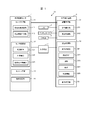
- FIG. 1 is an overall configuration diagram of an in-vehicle system S1 according to the present invention.
- the in-vehicle system S1 is mounted on a vehicle and includes an outside world recognition sensor 1, a navigation system 2, an electronic control device 3, an actuator 4, an input device 5, and a vehicle DB6. These are connected by signal lines as shown in FIG.
- a vehicle equipped with the in-vehicle system S1 will be referred to as a "own vehicle" in order to distinguish it from other vehicles.
- the outside world recognition sensor 1 detects the positions of landmarks existing around the own vehicle as outside world information.
- the outside world recognition sensor 1 is, for example, a camera or a laser radar.
- the vehicle-mounted system S1 includes only one external world recognition sensor 1, but the vehicle-mounted system S1 may include a plurality of external world recognition sensors 1.
- the navigation 2 outputs information such as the route, terrain, and latitude / longitude of the own vehicle.
- the electronic control device 3 determines the derivation of the landmark position, the control method of the own vehicle, and the like.
- the actuator 4 is a handle, a brake, an accelerator, etc. that change the direction and speed of the vehicle.
- the vehicle-mounted system S1 includes only one actuator 4, but the vehicle-mounted system S1 may include a plurality of actuators 4.
- the input device 5 reads, writes, and rewrites the information stored in the sensor storage unit 12 of the external world recognition sensor 1 and the information stored in the device storage unit 32 of the electronic control device 3.
- the input device 5 is, for example, a personal computer.
- the in-vehicle system S1 may include a plurality of input devices 5.
- the own vehicle DB6 is a database, and outputs the speed, yaw rate, winker input status, steering angle of the steering wheel, and the like of the own vehicle. Information on the speed, yaw rate, operating state of the winker and the steering wheel of the own vehicle is sequentially input to the own vehicle DB 6 from a sensor (not shown) mounted on the own vehicle.
- the outside world recognition sensor 1 includes a sensor processing unit 11, a sensor storage unit 12, a sensing unit 13, and a condition receiving unit 14.
- the hardware configuration of the sensor processing unit 11 will be described later.
- the sensor storage unit 12 is a non-volatile storage area, for example, a flash memory or an EEPROM (Electrically Erasable Programmable Read-Only Memory).
- the sensor processing unit 11 has a processing target determination unit 111 and an outside world information output unit 112.
- the processing condition 121, the outside world information 122, and the pre-processing outside world information 123 are stored in the sensor storage unit 12.
- the sensing unit 13 is a combination of sensor components, for example, a light source and a light receiving element.
- the sensing unit 13 performs sensing at a predetermined processing cycle, and stores the pre-processing external world information 123 in the sensor storage unit 12.
- the condition receiving unit 14 receives the processing condition 322 from the electronic control device 3 and stores it in the sensor storage unit 12 as the processing condition 121.
- the condition receiving unit 14 is, for example, a communication module corresponding to CAN (registered trademark) or IEEE802.3.
- the electronic control device 3 includes a device processing unit 31, a device storage unit 32, and a condition transmission unit 33.
- the hardware configuration of the device processing unit 31 will be described later.
- the device storage unit 32 is a non-volatile storage area, for example, a flash memory or EEPROM.
- the device processing unit 31 has a condition calculation unit 311 and a vehicle control unit 312.
- the device processing unit 31 stores the information received from the outside world recognition sensor 1, the navigation 2, and the own vehicle DB 6 in the device storage unit 32.
- the device storage unit 32 stores the condition creation source 321, the processing condition 322, the terrain 323, the route 324, and the outside world information 325.
- the condition transmission unit 33 is, for example, a communication module corresponding to CAN or IEEE802.3.
- the processing condition 121 stored in the sensor storage unit 12 and the processing condition 322 stored in the device storage unit 32 are the same.
- the outside world information 122 stored in the sensor storage unit 12 and the outside world information 325 stored in the device storage unit 32 are the same.
- the processing condition 322 is created by the condition calculation unit 311, and the processing condition 322 is transmitted from the electronic control device 3 to the outside world recognition sensor 1 by the condition transmission unit 33 and stored as the processing condition 121 in the sensor storage unit 12. Will be done.
- the outside world information 122 is created by the outside world information output unit 112, the outside world information 122 is transmitted from the outside world recognition sensor 1 to the electronic control device 3, and is stored in the device storage unit 32 as the outside world information 325.
- the processing condition 121 and the processing condition 322 are exactly the same including the data storage method
- the outside world information 122 and the outside world information 325 are exactly the same including the data storage method.
- the storage method and data representation of the data may be different.
- the configuration shown in FIG. 1 only shows a logical configuration, and there are no restrictions on the physical configuration.
- the sensor processing unit 11 and the sensor storage unit 12 may have a physical configuration mounted on the same device as the electronic control device 3.
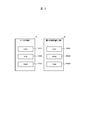
- FIG. 2 is a diagram showing the hardware configuration of the sensor processing unit 11 and the device processing unit 31.
- the sensor processing unit 11 includes a CPU 10001 which is a central arithmetic unit, a ROM 10002 which is a read-only storage device, and a RAM 10003 which is a readable and writable storage device.
- the processing target determination unit 111 and the outside world information output unit 112 are realized by the CPU 10002 expanding the program stored in the ROM 10002 into the RAM 1003 and executing the program.
- the sensor processing unit 11 is realized by FPGA (Field Programmable Gate Array), which is a rewritable logic circuit instead of the combination of CPU10001, ROM10002, and RAM1003, and ASIC (Application Specific Integrated Circuit), which is an integrated circuit for specific applications. You may. Further, the sensor processing unit 11 may be realized by a combination of different configurations, for example, a combination of the CPU 10001, ROM 10002, RAM 1003 and FPGA, instead of the combination of the CPU 10001, ROM 10002, and RAM 1003.
- FPGA Field Programmable Gate Array
- the device processing unit 31 includes a CPU 30001 which is a central arithmetic unit, a ROM 30002 which is a read-only storage device, and a RAM 30003 which is a read / write storage device.
- the condition calculation unit 311 and the vehicle control unit 312 are realized by the CPU 30002 developing the program stored in the ROM 30002 in the RAM 30003 and executing the program.
- the device processing unit 31 may be realized by FPGA or ASIC instead of the combination of CPU30001, ROM30002, and RAM30003.
- the device processing unit 31 may be realized by a combination of different configurations, for example, a combination of CPU30001, ROM30002, RAM30003 and FPGA, instead of the combination of CPU30001, ROM30002, and RAM30003.
- the condition creation source 321 is stored in the device storage unit 32 in advance, and the condition creation source 321 is not changed within the range described in this embodiment.
- the navigation 2 creates the route 324 in advance based on the operation of the user.
- the route 324 is information indicating a travel route on which the own vehicle will travel from now on.
- the terrain 323 is information on the nodes of the region including the route 324.
- the processing condition 322 is created by the condition calculation unit 311 with reference to the position of the own vehicle, the condition creation source 321, the terrain 323, and the route 324. Since the processing condition 322 is also affected by the position of the own vehicle, the processing condition 322 is created with high frequency, for example, every 200 ms.
- the pre-processing external world information 123 is information around the own vehicle collected by the external world recognition sensor 1, and is updated frequently, for example, every 200 ms.
- the outside world information 122 is created by the outside world information output unit 112 based on the processing condition 121 and the pre-processing outside world information 123. Then, the outside world information output unit 112 is transmitted to the electronic control device 3, and is stored in the device storage unit 32 as the outside world information 325.
- the electronic control device 3 inputs the outside world information 325 to the vehicle control unit 312. However, the electronic control device 3 itself may not use the outside world information 325, and the electronic control device 3 may transmit the outside world information 325 to another device connected to the electronic control device 3.
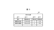
- FIG. 3 is a diagram showing an example of the condition creation source 321.
- the condition creation source 321 has a plurality of records, and each record has fields of condition 3211, range derivation formula 3212, priority 3213, and processing particle size 3214.
- the field of condition 3211 stores the condition to which the description of the record is applied. For example, the description "in route &intersection" in the first record of FIG. 3 is a node included in route 324 and terrain 323, and the attribute of the node in terrain 323 is "intersection". The condition is shown.
- a derivation formula for deriving the range to which the priority and the processing granularity described in the same record are applied is stored.
- the functions of f1 and f2 shown in FIG. 3 are derivation formulas of a range defined separately, and show that longitude, latitude, and rotation angle are used. A specific example of the range derivation formula will be described later.
- the "derivation formula" is a concept and does not necessarily have to be represented only by a mathematical formula, and the derivation process may be represented by using, for example, a flowchart or the like.
- the priority of the process in which the outside world recognition sensor 1 derives the landmark position is stored. In the present embodiment, it is shown that the smaller the value of the priority field, the higher the priority.
- the processing particle size 3214 the distance between the landmark positions when the outside world recognition sensor 1 outputs the landmark position is stored. For example, the processing particle size of "1 point / 1 m" indicates that the landmark position is output at 1 point for every 1 m, and the processing particle size of "1 point / 4 m" indicates that the landmark position is output at 1 point for every 4 m. Shown.
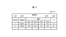
- FIG. 4 is a diagram showing an example of the processing condition 121 and the processing condition 322.
- the configuration of the processing condition 322 will be described below, but the configuration of the processing condition 121 is also the same.
- the processing condition 322 has a plurality of records, and each record has fields of priority 3221, processing particle size 3222, area 3223, and node 3224.
- the fields of priority 3221 and processing particle size 3222 correspond to the fields of priority 3213 and processing particle size 3214 of the condition creation source 321 shown in FIG.
- the field of the area 3223 stores information on the target area to which the priority and processing granularity of the record are applied.
- the target area is a rectangle parallel to the axis set in the coordinate system with respect to the own vehicle, and the area 3223 has the minimum and maximum values of the X coordinate and the minimum and maximum values of the Y coordinate. Value information is stored.
- the shape of the target area is not limited to a rectangle, and may be a parallelogram, a trapezoid, a rhombus, an ellipse, or the like.
- the information on the coordinates of the four corners of the rectangle may be stored in the field of the area 3223.
- the field of node 3224 stores the identifier of the node closest to the area indicated by the field of area 3223.
- the processing condition 121 and the processing condition 322 may not include the field of the node 3224.
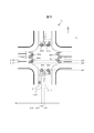
- FIG. 5 is a diagram showing an example of the intersection C. Since the terrain 323 and the route 324 will be described using the example of the intersection C shown in FIG. 5, the intersection C will be described first.
- the intersection C shown in FIG. 5 is an intersection in which the upper part of the drawing is north and roads running north-south and east-west intersect.
- separate nodes are set for each traveling direction of the road, and specifically, nodes N11 to N18 are set.
- node N11 and node N18 are both ends of the road shown at the bottom of the figure, but since node N11 is a node that enters the intersection and node N18 is a node that exits the intersection, they are separate nodes. It is said.
- the end of the road is the end closest to the intersection.
- Node N11 includes lane L111, lane L112, and lane L113.
- Node N12 also includes lane L121 and lane L122.
- the latitude of the end of the lane L111 is "La1”
- the longitude of the end of the lane L111 is "Lo1”. Since the lane L111, the lane L112, and the lane L113 are arranged in the horizontal direction shown in the drawing, the latitude of the end of the lane L112 and the lane L113 is also "La1".
- the longitude of the end of the lane L112 is "Lo2", and the longitude of the end of the lane L113 is "Lo3”.
- the longitudes of the lane L121 and the lane L122 included in the node N12 are both “Lo4".
- the latitude of the lane L121 is “La2”
- the latitude of the lane L122 is "La3".
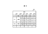
- FIG. 6 is a diagram showing an example of the terrain 323.
- Terrain 323 is composed of a plurality of records, each record having fields of node 3231, attribute 3232, lane 3233, latitude 3234, longitude 3235, and orientation 3236.
- a code indicating a representative point on the terrain is stored in the field of node 3231.
- the representative point is set for each road connected to the intersection so that the traveling route of the own vehicle can be specified by specifying the nodes in order, for example.
- the node is set for each traveling direction of the vehicle. For example, at the intersection C where the four roads shown in FIG. 5 intersect, it has 8 nodes in 4 ⁇ 2.
- the field of attribute 3232 indicates the attribute of the road immediately before reaching the node of the record. For example, if the road immediately before the node of the record is a straight road, "straight line” is stored in the attribute 3232, and if the road immediately before the node of the record is an intersection, "intersection” is stored in the attribute. For example, at the intersection C shown in FIG. 5, since the node N11 exists at a position where it enters the intersection C from the lower part of the drawing, a “straight line” is stored in the attribute 3232. Further, since the node N12 exists at a position where it enters from the intersection C to the left side of the drawing, the attribute 3232 stores the "intersection".
- Lane 3233 stores information that identifies the lane included in the node of the record. For example, since the node N11 at the intersection C shown in FIG. 5 includes three lanes, it is described as it is in the terrain 323 shown in FIG.
- Latitude 3234 stores the latitude of the end of the lane of the record.
- the longitude 3235 stores the longitude of the end of the lane of the record.
- Direction 3236 stores the direction of the lane of the record.
- the lane orientation is, for example, a straight line approximation of a lane and the angle formed by that straight line with true north.
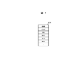
- FIG. 7 is a diagram showing an example of the route 324.
- the route 324 is described in the order in which the nodes on the route on which the vehicle travels travel.
- Route 324 utilizes the identifier of node 3231 in terrain 323.
- the vehicles are listed from top to bottom in the order in which they travel.
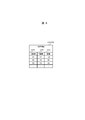
- FIG. 8 is a diagram showing an example of the outside world information 122 and the outside world information 325.
- the configuration of the outside world information 122 will be described below, but the configuration of the outside world information 325 is also the same.
- the outside world information 122 is composed of a plurality of records, and each record has fields of X coordinate 1221, Y coordinate 1222, and accuracy 1223.
- the X coordinate 1221 and the Y coordinate 1222 store the position information of the landmark with respect to the own vehicle. Specifically, the center of the own vehicle is the origin, and the front of the own vehicle passing through the center of the own vehicle is the positive direction of the X-axis.
- the field with accuracy 1223 stores an indicator of the accuracy of the landmark's position on the record. In the example shown in FIG. 8, the larger the value stored in the accuracy 1223, the more likely it is.
- the index stored in the accuracy 1223 is determined based on, for example, when the external world recognition sensor 1 is a laser radar, the magnitude of the reflection intensity difference between the road surface around the landmark position and the landmark position.
- Range derivation formula The information stored in the range derivation formula 3212 of FIG. 3 will be described. There are a plurality of variations of the range derivation formula other than f1 and f2 shown in FIG. 3, but all of them utilize the terrain 323, the route 324, and the position of the own vehicle. In the following, two examples of the range derivation formula will be described with reference to FIGS. 9 to 12.
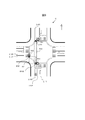
- FIG. 9 is a diagram showing an example of the range calculated by the range derivation formula f1
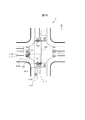
- FIG. 10 is a diagram showing an example of the range calculated by the range derivation formula 21.
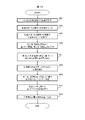
- FIG. 11 is a flowchart showing the calculation process of the range derivation formula f1
- FIG. 12 is a flowchart showing the calculation process of the range derivation formula f2. Note that FIGS. 9 and 10 show the intersection C shown above, and the terrain 323 is the one shown in FIG.
- the area A11 is calculated when the vehicle advances from the node N11 to the node N12
- the area A12 is calculated when the vehicle advances from the node N11 to the node N14.
- the area A21 is calculated when the vehicle advances from the node N11 to the node N12
- the area A22 is calculated when the vehicle advances from the node N11 to the node N14.
- the range derivation formula f1 and the range derivation formula f2 have different calculated regions even under the same conditions. The calculation of the area is as follows, for example.
- step S411 the condition calculation unit 311 determines whether or not the vehicle is going straight from the current position of the vehicle to the target node. If it is determined that the vehicle is going straight, the process proceeds to step S412, and if it is determined that the vehicle is not going straight, the process proceeds to step S413.
- step S412 the condition calculation unit 311 sets the target area as the area from the current lane of the own vehicle to the target node by the width of the lane, for example, the area A12 in FIG.
- step S413 the condition calculation unit 311 extracts the shortest distance lane combination.
- the combination of the shortest distance lanes is extracted from the combination of the three lanes L111, L112, and L113 included in the node N11 and the two lanes L121 and L122 included in the node N12. ..
- step S414 the condition calculation unit 311 sets a rectangular area whose diagonal is the end of each lane of the combination extracted in step S413 as the target area.
- the target region is the rectangular region A11 having the end E113 of the lane L113 and the end E121 of the lane L121 diagonally.
- step S421 is the same as step S411, the description thereof will be omitted.
- the condition calculation unit 311 proceeds to step S422 when making an affirmative determination in step S421, and proceeds to step S423 when making a negative determination in step S421.
- step S422 the "width of the traveling lane in which the own vehicle is traveling" in step S412 is replaced with "the total width of the node in which the own vehicle is traveling". Therefore, the area A22 shown in FIG. 10 is the target area.
- step S423 contrary to step S413, the combination of lanes having the longest distance is extracted.
- lanes L111 and L122 are extracted.
- step S424 is the same as in step S414.
- the rectangular area A21 whose diagonal is the end E111 of the lane L111 and the end E122 of the lane L122 is the target area. ..
- FIG. 13 is a flowchart showing the operation of the in-vehicle system S1.
- the in-vehicle system S1 executes the process shown in FIG. 13 at a predetermined cycle, for example, at the end of 100 ms.
- the condition calculation unit 311 acquires the terrain 323, the route 324, the latitude, longitude, and the direction of the own vehicle from the navigation 2, and acquires the information of the own vehicle speed, the yaw rate, and the steering angle from the own vehicle DB6.
- step S102 the condition calculation unit 311 derives the latitude and longitude ranges to be processed based on the latitude, longitude, and direction of the own vehicle received in step S101 and the preset sensing range.
- the sensing range is preset in the device storage unit 32 as a rectangle from 100 m behind to 300 m ahead and 200 m left to 200 m right around the own vehicle.
- step S102 for example, the latitude and longitude of four points that are the vertices of the rectangular region to be processed are calculated.
- step S103 the condition calculation unit 311 detects the nodes included in the latitude / longitude range to be processed calculated in step S102 among the nodes included in the terrain 323 received in step S101.
- the representative points of the lanes included in each node for example, the latitude and longitude of the lane described first, are the latitudes to be processed derived in step S102. Detects nodes that fall within the range of and longitude.
- the condition calculation unit 311 calculates the processing condition 322 using the condition creation source 321.
- the condition creation source 321 is represented as shown in FIG. 3
- the terrain 323 is represented as shown in FIG. 6, and the route 324 is represented as shown in FIG. 7,
- the operation is as follows. That is, among the conditions included in the condition creation source 321, the nodes that meet the conditions are searched in order from the upper row, the range is calculated according to the range derivation formula set in the same row, and recorded in the processing condition 322 as the area 3223. .. Further, the priority 3213 and the processing particle size 3214 set in the same line are recorded in the processing condition 322 as the priority 3221 and the processing particle size 3222.
- the attribute of the terrain 323 in FIG. 6 is "intersection” among the nodes included in the route 324 in FIG.
- the node that is "" is searched, and "N12" is extracted.
- the range is derived according to the range derivation formula "f1 (La, Lo, ⁇ )" also set in the first line of the condition creation source 321 in FIG. 3, and the latitude ranges La1 to La2 and the longitude ranges Lo3 to Lo4 are obtained. Derived. Then, the priority "1" and the processing granularity "1 point / 1m" set in the first line of the condition creation source 321 of FIG.
- the processing particle size may be converted so as to be expressed by a relative magnification (2) with respect to a predetermined processing particle size (1 / 2m).
- the priority 3221 and the processing are performed for all the rows of the condition creation source 321 of FIG. 3 as shown in FIG.
- the particle size 3222 can be determined.
- step S105 the condition calculation unit 311 estimates the position and orientation of the own vehicle in the next cycle based on the information received from the own vehicle DB6 in step S101, and moves and rotates the range calculated in step S104 to correct it. For example, when the latitude / longitude, direction, speed, and yaw rate of the own vehicle are received from the own vehicle DB6, the time of the next cycle when the own vehicle moves at the same speed / iso-yaw rate until the time of the next cycle Calculate the amount of change in the position and orientation of your vehicle at the time.
- a rectangle including a range calculated in step S104 for example, a range obtained by converting the latitude range La1 to La2 and the longitude range Lo3 to Lo4 into the own vehicle center coordinate system in the own vehicle position / direction in the next cycle, for example, the traveling direction coordinate range Xl1.
- ⁇ Xu1 and the lateral coordinate range Yl1 to Yu1 are defined as the range after shift / rotation correction.
- step S106 the condition calculation unit 311 generates the processing condition 322 by combining the priority 3221 calculated in step S104, the processing particle size 3222, and the shift / rotation correction range in step S105, and transmits the processing condition 322 to the processing target determination unit 111. ..
- step S107 the processing target determination unit 111 of the outside world recognition sensor 1 derives the outside world information 122 based on the processing condition 322 transmitted in step S106.
- the processing condition is expressed as shown in FIG. 4, the first line in which "1" having the highest priority is set is searched.
- processing is performed according to a rule preset in the sensor storage unit 12, for example, a rule of processing in ascending order of line numbers.
- the outside world information 122 (X, Y) detected in the range is specified by the specified processing particle size based on the range and the processing particle size set in the line extracted as a result of the search.
- the accuracy may be set for each landmark position as shown in FIG.
- the function to set the accuracy is, for example, a function to set the accuracy based on the edge position error of the landmark, which depends on the degree of fading of the landmark and the illuminance of the surroundings.
- the above processing may be performed according to a rule set in advance in the sensor storage unit 12. This rule is, for example, repeating until the maximum number of landmarks reaches 64, or if the maximum number is exceeded during processing in a certain range, the maximum number of landmarks is processed in order from the landmark position closest to the vehicle. is there.
- step S108 the outside world information output unit 112 transmits the outside world information 122 derived in step S107 to the vehicle control unit 312.
- the received landmark position information is stored, for example, in the device storage unit 32 as external world information 325.
- the outside world information 325 may be discarded after the vehicle control process of the vehicle control unit 312.
- the in-vehicle system S1 is mounted on a vehicle and includes an electronic control device 3 and an outside world recognition sensor 1.
- the outside world recognition sensor 1 includes a sensing unit 13 that acquires the pre-processing outside world information 123 by sensing.
- the in-vehicle system S1 associates the information for identifying the area on the map with the processing priority of the pre-processing external world information 123 acquired by the external world recognition sensor based on the vehicle position, the vehicle traveling direction, and the map information.
- a condition calculation unit 311 for calculating the processing condition 322 and a processing target determination unit 111 for creating the outside world information 122 having a smaller amount of information than the pre-processing outside world information 123 based on the pre-processing outside world information 123 and the processing condition 121 are provided. .. Therefore, even in an environment where there is a lot of outside world information such as an intersection, based on the calculated processing condition 322, the information of the feature points of the region having high priority, in other words, the outside world information 122 which has less information than the pre-processing outside world information 123 Is created, so that the electronic control device 3 does not necessarily have a high computing power.
- the processing condition 121 corresponds the processing particle size 3222, which is the priority 3221 and the spatial density of the output, to the area 3223 on the map. Therefore, information can be obtained not only by selecting the area according to the priority but also by the processing particle size set for each area.
- the outside world information 122 is information related to the landmark, and the processing of the pre-processing outside world information 123 is the feature point derivation processing of the landmark. Therefore, the landmark information corresponding to the processing condition 322 is obtained as the outside world information 122.
- the landmark is a lane mark existing on the road
- the processing particle size 3222 is the point density for deriving the feature point of the lane mark. Therefore, the higher the processing particle size 3222, the more feature points can be derived from one lane mark per detected unit length.
- the condition calculation unit 311 specifies the traveling direction of the vehicle based on the position of the vehicle and the route 324 which is the traveling route of the vehicle calculated in advance. Therefore, it is possible to acquire information in an appropriate area at a high density according to the traveling route of the vehicle. Further, for example, when turning left in an area where the vehicle is known not to travel, for example, when turning left at an intersection, it is possible not to include information on the right turn side or the straight-ahead side in the outside world information 122.
- the electronic control device 3 includes a condition calculation unit 311 and a condition transmission unit 33 that transmits the processing condition 322 to the outside world recognition sensor 1.
- the outside world recognition sensor 1 includes a sensing unit 13 and a processing target determination unit 111.
- the outside world recognition sensor 1 is mounted on a vehicle and has a sensing unit 13 that acquires pre-processed outside world information by sensing, and a map created based on the position of the vehicle, the traveling direction of the vehicle, and map information. Processing based on the condition receiving unit 14 that acquires the processing condition 121 that associates the information that identifies the area with the processing priority of the pre-processing external world information acquired by the external world recognition sensor, and the pre-processing external world information 123 and the processing condition 121. It includes a processing target determination unit 111 that creates the outside world information 122 whose amount of information is smaller than that of the front outside world information 123.
- the outside world recognition sensor 1 has a larger amount of information than the information of the feature points in the high priority area, in other words, the pre-processing outside world information 123, based on the calculated processing condition 322, even in an environment where there is a lot of outside world information such as an intersection. Creates external world information 122 with few. As a result, even if the computing power of the electronic control device 3 is not necessarily high, it is possible to deal with an intersection having a large amount of information.
- a plurality of condition creation sources 321 are stored in the device storage unit 32 of the electronic control device 3, and any condition creation source is obtained by the condition calculation unit 311 based on the information indicating the country / region in which the vehicle is traveling. You may decide whether to use 321.
- the condition calculation unit 311 uses different condition creation sources 321 for a country or region having a traffic rule in which the vehicle travels on the right side in the traveling direction and a country or region having a traffic rule in which the vehicle travels on the left side in the traveling direction.
- the processing condition 322 may be calculated using the above.
- the outside world recognition sensor 1 outputs information on the feature points of landmarks that are stationary objects as outside world information 122.
- the outside world recognition sensor 1 may detect a moving object, for example, another vehicle, a pedestrian, a bicycle, or the like, and output the information thereof.
- the processing condition 322 includes a processing particle size 3222.
- the processing condition 322 does not have to include the processing particle size 3222. Even in this case, since the outside world information 122 includes the landmark information limited to the target area instead of the landmark information of the entire area around the own vehicle, the same effect as that of the first embodiment can be obtained. can get.
- FIG. 1 A second embodiment of the in-vehicle system will be described with reference to FIG.
- the same components as those in the first embodiment are designated by the same reference numerals, and the differences will be mainly described.
- the points not particularly described are the same as those in the first embodiment.
- the present embodiment is different from the first embodiment in that the processing condition 322 is mainly changed based on the past external world information 325. As a result, more information that is important for vehicle control can be collected without increasing the total processing amount, so that high safety can be ensured with the same processing amount.
- step S511 which will be described next, is added between step S504 and step S505 of FIG.
- FIG. 14 is a flowchart showing the processing of the in-vehicle system according to the second embodiment. However, the description of the steps similar to those in the first embodiment will be omitted.
- step S511 executed after step S504, the condition calculation unit 311 rewrites at least one of the priority and the processing particle size calculated in step S104 based on the accuracy of the outside world information 325 received from the outside world information output unit 112.
- condition calculation unit 311 may lower the processing granularity of the area where highly accurate information has already been obtained to reduce the number of output points, or lower the priority to make it difficult to output.
- the external world information 325 acquired immediately before is sorted in ascending order by the value of the X coordinate, a range in which the accuracy is larger than a predetermined threshold value, for example 80, and is continuous is specified, and priority is given in that range. Change the degree to "3" and the processing particle size to "1 point / 5m".
- the outside world information 122 includes a certainty 1223 indicating the certainty.
- the condition calculation unit 311 corrects the processing conditions based on the accuracy 1223. Therefore, the condition calculation unit 311 can correct the processing condition 322 based on the surrounding information acquired in the past.
- the condition calculation unit 311 lowers the priority of the region under the processing condition 322 when the accuracy of the region in the acquired external world information 325 is equal to or higher than a predetermined value. Therefore, more information of high importance for vehicle control can be collected without increasing the total processing amount, so that high safety can be ensured with the same processing amount.
- FIG. 1 A third embodiment of the in-vehicle system will be described with reference to FIG.
- the same components as those in the first embodiment are designated by the same reference numerals, and the differences will be mainly described.
- the points not particularly described are the same as those in the first embodiment.
- the present embodiment is different from the first embodiment in that the processing condition 322 is modified mainly based on the operation of the vehicle. As a result, even if the user moves the vehicle in a direction different from the predetermined route, more information that is important for controlling the vehicle can be collected without increasing the total processing amount. , The effect of ensuring high safety with the same amount of processing is expected.
- FIG. 15 is a flowchart showing the processing of the in-vehicle system according to the third embodiment. Since the processing up to step S503 is the same as that of the first embodiment, the description thereof will be omitted.
- the condition calculation unit 311 determines whether or not the steering angle matches the path. For example, it is determined whether or not the steering angle matches the left turn angle in a situation where a left turn should be made if the route is followed.
- the condition calculation unit 311 proceeds to step S504 when it determines that the steering angle matches the route, and proceeds to step S522 when it determines that the steering angle does not match the route.
- step S504 the range, priority, and processing granularity are calculated using the route information as in the first embodiment, and the process proceeds to step S505.
- step S522 the condition calculation unit 311 estimates the node to which the own vehicle travels.
- step S523 the condition calculation unit 311 calculates the range, priority, and processing granularity using the nodes estimated in step S522, and proceeds to step S505. Since the processing after step S505 is the same as that of the first embodiment, the description thereof will be omitted.
- the condition calculation unit 311 specifies the traveling direction of the vehicle based on the position of the vehicle, the travel path of the vehicle calculated in advance, or the steering angle of the vehicle. Therefore, it is possible to deal with the case where the vehicle travels off the route 324.
- FIG. 1 A fourth embodiment of the in-vehicle system will be described with reference to FIG.
- the same components as those in the first embodiment are designated by the same reference numerals, and the differences will be mainly described.
- the points not particularly described are the same as those in the first embodiment.
- the present embodiment is different from the first embodiment mainly in that the electronic control device is provided with a processing target determination unit.
- FIG. 16 is an overall configuration diagram of the in-vehicle system S4 according to the fourth embodiment. Any configuration of the vehicle-mounted system S4 is included in the vehicle-mounted system S1 according to the first embodiment. However, the place where a specific function exists is different. Specifically, in the first embodiment, the processing target determination unit 111 provided in the outside world recognition sensor 1 is provided in the electronic control device 3 as the processing target determination unit 313 in the present embodiment. The operation of the processing target determination unit 313 is the same as that of the processing target determination unit 111 in the first embodiment.
- the electronic control device 3 does not need to transmit the calculated processing condition 322 to the outside world recognition sensor 1, so that the condition transmission unit 33 does not have to be provided.
- the outside world recognition sensor 1 does not include a processing target determination unit 111, an outside world information output unit 112, and a condition reception unit 14.
- the outside world recognition sensor 1 includes a pre-processing outside world information output unit 113 that transmits the acquired pre-processing outside world information 123 to the electronic control device 3.
- the electronic control device 3 includes a condition calculation unit 311 and a processing target determination unit 313.
- the outside world recognition sensor 1 includes a pre-processing outside world information output unit 113 that transmits the pre-processing outside world information 123 to the electronic control device 3. Therefore, the vehicle control unit 312 of the electronic control device 3 can handle intersections with a large amount of information by targeting only the external world information 325 calculated by the processing target determination unit 313 using the processing condition 322.
- the electronic control device 3 is mounted on the vehicle and is connected to the outside world recognition sensor 1 that acquires the pre-processing outside world information 123 by sensing.
- the electronic control device 3 determines the information for identifying the area on the map and the processing priority of the pre-processing external world information 123 acquired by the external world recognition sensor 1 based on the vehicle position, the vehicle traveling direction, and the map information.
- the pre-processing external world information acquisition unit 34 that acquires the pre-processing external world information 123 from the external world recognition sensor 1, the pre-processing external world information 123, and the processing condition 322. It includes a processing target determination unit 313 that creates the outside world information 325, which has a smaller amount of information than the outside world information 123.
- the configuration of the functional block is only an example.
- Several functional configurations shown as separate functional blocks may be integrally configured, or the configuration represented by one functional block diagram may be divided into two or more functions. Further, a part of the functions of each functional block may be provided by another functional block.
Landscapes
- Engineering & Computer Science (AREA)
- Physics & Mathematics (AREA)
- General Physics & Mathematics (AREA)
- Theoretical Computer Science (AREA)
- Multimedia (AREA)
- Automation & Control Theory (AREA)
- Transportation (AREA)
- Mechanical Engineering (AREA)
- Mathematical Physics (AREA)
- Human Computer Interaction (AREA)
- Quality & Reliability (AREA)
- Computer Vision & Pattern Recognition (AREA)
- Navigation (AREA)
- Traffic Control Systems (AREA)
- Control Of Driving Devices And Active Controlling Of Vehicle (AREA)
Abstract
Description
本発明の第2の態様による外界認識センサは、車両に搭載される外界認識センサであって、センシングにより処理前外界情報を取得するセンシング部と、前記車両の位置、前記車両の進行方向、および地図情報に基づいて作成された、地図上の領域を特定する情報と前記外界認識センサが取得した前記処理前外界情報の処理の優先度とを対応付けた処理条件を取得する受信部と、前記処理前外界情報および前記処理条件に基づき前記処理前外界情報よりも情報量が少ない外界情報を作成する処理対象決定部と、を備える。
本発明の第3の態様による電子制御装置は、車両に搭載され、センシングにより処理前外界情報を取得する外界認識センサと接続される電子制御装置であって、前記電子制御装置は、前記車両の位置、前記車両の進行方向、および地図情報に基づいて、地図上の領域を特定する情報と前記外界認識センサが取得した前記処理前外界情報の処理の優先度とを対応付けた処理条件を算出する条件算出部と、前記外界認識センサから前記処理前外界情報を取得する処理前外界情報取得部と、前記処理前外界情報および前記処理条件に基づき前記処理前外界情報よりも情報量が少ない外界情報を作成する処理対象決定部と、を備える。
図1は、本発明に係る車載システムS1の全体構成図である。車載システムS1はある車両に搭載され、外界認識センサ1と、ナビ2と、電子制御装置3と、アクチュエータ4と、入力装置5と、自車DB6とを備える。これらは図1に示すように信号線で接続される。以下では、車載システムS1を搭載する車両を他の車両と区別するために「自車両」と呼ぶ。
センサ記憶部12および装置記憶部32に格納されるデータの概要を説明する。条件作成源321はあらかじめ装置記憶部32に格納されており、本実施の形態で説明する範囲では条件作成源321は変更されない。本実施の形態では、ユーザの操作に基づきナビ2が事前に経路324を作成している。経路324は、これから自車両が走行する走行経路を示す情報である。地形323は、経路324を含む領域のノードの情報である。処理条件322は条件算出部311により自車両の位置、条件作成源321、地形323、および経路324を参照して作成される。処理条件322は自車両の位置の影響も受けるため、処理条件322は高い頻度で、たとえば200msごとに作成される。
図3は、条件作成源321の一例を示す図である。条件作成源321は複数のレコードを有し、各レコードは、条件3211、範囲導出式3212、優先度3213、および処理粒度3214のフィールドを有する。条件3211のフィールドには、そのレコードの記載を適用する条件が格納される。たとえば、図3の最初のレコードに記載された「経路内&交差」という記載は、経路324および地形323に含まれるノードであって、かつ地形323における当該ノードの属性が「交差」である、という条件を示す。
図4は、処理条件121および処理条件322の一例を示す図である。以下では処理条件322の構成を説明するが、処理条件121の構成も同様である。処理条件322は複数のレコードを有し、各レコードは、優先度3221、処理粒度3222、領域3223、およびノード3224のフィールドを有する。優先度3221および処理粒度3222のフィールドは、図3に示した条件作成源321の優先度3213および処理粒度3214のフィールドに対応する。領域3223のフィールドには、そのレコードの優先度および処理粒度を適用する対象となる対象領域の情報が格納される。
図5は交差点Cの一例を示す図である。地形323および経路324は、図5に示す交差点Cの例を使って説明するので、先に交差点Cを説明する。図5に示す交差点Cは、図示上方が北であり、南北および東西に走る道路が交差する交差点である。図5に示す例では、道路の進行方向ごとに別々のノードを設定しており、具体的にはノードN11~ノードN18が設定されている。たとえばノードN11とノードN18は、いずれも図示下方に示す道路の端部であるが、ノードN11は交差点へ侵入する側のノードであり、ノードN18は交差点から退出する側のノードなので、別々のノードとしている。なお道路の端部とは、交差点に最も近い端部とする。
図6は、地形323の一例を示す図である。地形323は複数のレコードから構成され、各レコードはノード3231、属性3232、車線3233、緯度3234、経度3235、および方位3236のフィールドを有する。
図7は、経路324の一例を示す図である。経路324は、車両が走行する経路上のノードを走行する順番に記載したものである。経路324は地形323におけるノード3231の識別子を利用する。図7に示す例では、車両が走行する順番で上から下に記載している。
図8は、外界情報122および外界情報325の一例を示す図である。以下では外界情報122の構成を説明するが、外界情報325の構成も同様である。外界情報122は複数のレコードから構成され、各レコードはX座標1221、Y座標1222、および確度1223のフィールドを有する。X座標1221およびY座標1222には、自車両を基準としたランドマークの位置情報が格納される。具体的には、自車両の中心を原点とし、自車両の中心を通る自車両の前方をX軸の正方向とする。
図3の範囲導出式3212に格納される情報を説明する。範囲導出式には図3に示したf1およびf2以外にも複数のバリエーションが存在するが、いずれも地形323、経路324、および自車両の位置を利用する。以下では、範囲導出式の2つの例を図9~図12を参照して説明する。
図13は車載システムS1の動作を表すフローチャートである。車載システムS1は図13に示す処理を、所定の周期、たとえば100ms終期で実行する。ステップS101では条件算出部311は、ナビ2から地形323、経路324、自車両の緯度、経度、および方位を取得し、自車DB6から自車速度、ヨーレート、操舵角の情報を取得する。
(1)車載システムS1は、車両に搭載され、電子制御装置3および外界認識センサ1を備える。外界認識センサ1は、センシングにより処理前外界情報123を取得するセンシング部13を備える。車載システムS1は、車両の位置、車両の進行方向、および地図情報に基づいて、地図上の領域を特定する情報と外界認識センサが取得した処理前外界情報123の処理の優先度とを対応付けた処理条件322を算出する条件算出部311と、処理前外界情報123および処理条件121に基づき処理前外界情報123よりも情報量が少ない外界情報122を作成する処理対象決定部111と、を備える。そのため、交差点など外界情報が多い環境であっても、算出された処理条件322に基づき、優先度が高い領域の特徴点の情報、換言すると処理前外界情報123よりも情報量が少ない外界情報122が作成されるので、電子制御装置3の演算能力が必ずしも高くなくても対応ができる。
電子制御装置3の装置記憶部32に条件作成源321が複数格納され、条件算出部311がナビ2から取得する自車が走行中の国・地域を示す情報に基づいて、いずれの条件作成源321を使用するかを決めてもよい。たとえば条件算出部311は、車両が進行方向の右側を走行する交通規則を有する国や地域と、車両が進行方向の左側を走行する交通規則を有する国や地域とでは、異なる条件作成源321を用いて処理条件322を算出してもよい。
上述した第1の実施の形態では、外界認識センサ1は外界情報122として静止物体であるランドマークの特徴点の情報を出力した。しかし外界認識センサ1は、動いている物体、たとえば他の車両、歩行者、自転車などを検出し、それらの情報を出力してもよい。
上述した第1の実施の形態では、処理条件322には処理粒度3222が含まれた。しかし処理条件322には処理粒度3222が含まれなくてもよい。この場合であっても、外界情報122には自車両の周囲における全域のランドマーク情報ではなく、対象領域に限定されたランドマーク情報が含まれるので、第1の実施の形態と同様の効果が得られる。
図14を参照して、車載システムの第2の実施の形態を説明する。以下の説明では、第1の実施の形態と同じ構成要素には同じ符号を付して相違点を主に説明する。特に説明しない点については、第1の実施の形態と同じである。本実施の形態では、主に、処理条件322を、過去の外界情報325に基づいて変更させる点で、第1の実施の形態と異なる。これにより、総処理量を増やさずに、車両の制御に重要度の高い情報をより多く収集できるようになるため、同じ処理量で高い安全性を確保することができる。
図15を参照して、車載システムの第3の実施の形態を説明する。以下の説明では、第1の実施の形態と同じ構成要素には同じ符号を付して相違点を主に説明する。特に説明しない点については、第1の実施の形態と同じである。本実施の形態では、主に、車両の操作に基づいて処理条件322を修正する点で、第1の実施の形態と異なる。これにより、ユーザが所定の経路とは異なる方向へ車両が移動させた場合であっても、総処理量を増やさずに、車両の制御に重要度の高い情報をより多く収集できるようになるため、同じ処理量で高い安全性を確保する効果が期待される。
(10)条件算出部311は、車両の位置および予め算出された車両の走行経路、または車両の操舵角に基づき車両の進行方向を特定する。そのため、車両が経路324を外れて走行する場合にも対処できる。
図16を参照して、車載システムの第4の実施の形態を説明する。以下の説明では、第1の実施の形態と同じ構成要素には同じ符号を付して相違点を主に説明する。特に説明しない点については、第1の実施の形態と同じである。本実施の形態では、主に、電子制御装置に処理対象決定部が備えられる点で、第1の実施の形態と異なる。
(11)電子制御装置3は、条件算出部311と、処理対象決定部313とを備える。外界認識センサ1は、処理前外界情報123を電子制御装置3に送信する処理前外界情報出力部113を備える。そのため電子制御装置3の車両制御部312は、処理条件322を用いて処理対象決定部313が算出した外界情報325のみを処理対象とすることで、情報量が多い交差点などにも対応できる。
日本国特許出願2019-90541(2019年5月13日出願)
3…電子制御装置
13…センシング部
14…条件受信部
33…条件送信部
34…処理前外界情報取得部
111…処理対象決定部
112…外界情報出力部
113…処理前外界情報出力部
121、322…処理条件
122、325…外界情報
123…処理前外界情報
311…条件算出部
313…処理対象決定部
321…条件作成源
323…地形
324…経路
Claims (11)
- 車両に搭載され、電子制御装置および外界認識センサを備える車載システムであって、
前記外界認識センサは、センシングにより処理前外界情報を取得するセンシング部を備え、
前記車両の位置、前記車両の進行方向、および地図情報に基づいて、地図上の領域を特定する情報と前記外界認識センサが取得した前記処理前外界情報の処理の優先度とを対応付けた処理条件を算出する条件算出部と、
前記処理前外界情報および前記処理条件に基づき前記処理前外界情報よりも情報量が少ない外界情報を作成する処理対象決定部と、を備える車載システム。 - 請求項1に記載の車載システムにおいて、
前記処理条件は、前記優先度および出力の空間的な密度である処理粒度を前記地図上の領域に対応づけたものである車載システム。 - 請求項2に記載の車載システムにおいて、
前記外界情報はランドマークに関する情報であり、
前記処理前外界情報の処理とは前記ランドマークの特徴点導出処理である車載システム。 - 請求項3に記載の車載システムにおいて、
前記ランドマークは路上に存在するレーンマークであり、前記処理粒度は前記レーンマークの特徴点導出の点密度である車載システム。 - 請求項1に記載の車載システムにおいて、
前記外界情報には確からしさを示す確度が含まれ、
前記条件算出部は、前記確度に基づき前記処理条件を補正する車載システム。 - 請求項5に記載の車載システムにおいて、
前記条件算出部は、取得済みの前記外界情報において第1領域の前記確度が所定値以上の場合に、前記処理条件における前記第1領域の優先度を低下させる車載システム。 - 請求項1に記載の車載システムにおいて、
前記条件算出部は、前記車両の位置および予め算出された前記車両の走行経路、または前記車両の操舵角に基づき前記車両の進行方向を特定する車載システム。 - 請求項1に記載の車載システムにおいて、
前記電子制御装置は、
前記条件算出部と、
前記処理条件を前記外界認識センサに送信する条件送信部とを備え、
前記外界認識センサは、前記センシング部と、前記処理対象決定部とを備える車載システム。 - 請求項1に記載の車載システムにおいて、
前記電子制御装置は、前記条件算出部と、前記処理対象決定部とを備え、
前記外界認識センサは、前記処理前外界情報を前記電子制御装置に送信する処理前外界情報出力部を備える車載システム。 - 車両に搭載される外界認識センサであって、
センシングにより処理前外界情報を取得するセンシング部と、
前記車両の位置、前記車両の進行方向、および地図情報に基づいて作成された、地図上の領域を特定する情報と前記外界認識センサが取得した前記処理前外界情報の処理の優先度とを対応付けた処理条件を取得する受信部と、
前記処理前外界情報および前記処理条件に基づき前記処理前外界情報よりも情報量が少ない外界情報を作成する処理対象決定部と、を備える外界認識センサ。 - 車両に搭載され、センシングにより処理前外界情報を取得する外界認識センサと接続される電子制御装置であって、
前記電子制御装置は、
前記車両の位置、前記車両の進行方向、および地図情報に基づいて、地図上の領域を特定する情報と前記外界認識センサが取得した前記処理前外界情報の処理の優先度とを対応付けた処理条件を算出する条件算出部と、
前記外界認識センサから前記処理前外界情報を取得する処理前外界情報取得部と、
前記処理前外界情報および前記処理条件に基づき前記処理前外界情報よりも情報量が少ない外界情報を作成する処理対象決定部と、を備える電子制御装置。
Priority Applications (2)
| Application Number | Priority Date | Filing Date | Title |
|---|---|---|---|
| DE112020001870.9T DE112020001870B4 (de) | 2019-05-13 | 2020-04-28 | Fahrzeuginternes System, Externalitätserkennungssensor, elektronische Steuervorrichtung |
| US17/609,487 US11961311B2 (en) | 2019-05-13 | 2020-04-28 | On-vehicle system, externality recognition sensor, electronic control device |
Applications Claiming Priority (2)
| Application Number | Priority Date | Filing Date | Title |
|---|---|---|---|
| JP2019-090541 | 2019-05-13 | ||
| JP2019090541A JP7223629B2 (ja) | 2019-05-13 | 2019-05-13 | 車載システム、外界認識センサ、電子制御装置 |
Publications (1)
| Publication Number | Publication Date |
|---|---|
| WO2020230637A1 true WO2020230637A1 (ja) | 2020-11-19 |
Family
ID=73222807
Family Applications (1)
| Application Number | Title | Priority Date | Filing Date |
|---|---|---|---|
| PCT/JP2020/018199 Ceased WO2020230637A1 (ja) | 2019-05-13 | 2020-04-28 | 車載システム、外界認識センサ、電子制御装置 |
Country Status (4)
| Country | Link |
|---|---|
| US (1) | US11961311B2 (ja) |
| JP (1) | JP7223629B2 (ja) |
| DE (1) | DE112020001870B4 (ja) |
| WO (1) | WO2020230637A1 (ja) |
Families Citing this family (2)
| Publication number | Priority date | Publication date | Assignee | Title |
|---|---|---|---|---|
| JP7604267B2 (ja) | 2021-02-26 | 2024-12-23 | 本田技研工業株式会社 | 地図生成装置 |
| DE102021111325B4 (de) * | 2021-05-03 | 2025-05-22 | Bayerische Motoren Werke Aktiengesellschaft | Verfahren und Assistenzeinrichtung zum Unterstützen eines Fahrbetriebs eines Kraftfahrzeugs und Kraftfahrzeug |
Citations (3)
| Publication number | Priority date | Publication date | Assignee | Title |
|---|---|---|---|---|
| JP2011044063A (ja) * | 2009-08-24 | 2011-03-03 | Nissan Motor Co Ltd | 車両運転支援装置及び支援方法 |
| JP2018091315A (ja) * | 2016-12-07 | 2018-06-14 | 株式会社オートネットワーク技術研究所 | エンジン停止始動判断装置及びコンピュータプログラム |
| JP2018106676A (ja) * | 2016-12-22 | 2018-07-05 | パナソニック インテレクチュアル プロパティ コーポレーション オブ アメリカPanasonic Intellectual Property Corporation of America | 情報処理装置、被操作車両、情報処理方法及びプログラム |
Family Cites Families (31)
| Publication number | Priority date | Publication date | Assignee | Title |
|---|---|---|---|---|
| JP3896852B2 (ja) * | 2002-01-16 | 2007-03-22 | 株式会社デンソー | 車両用衝突被害軽減装置 |
| JP2004217175A (ja) * | 2003-01-17 | 2004-08-05 | Toyota Motor Corp | 車間距離制御装置 |
| DE102006061390B4 (de) * | 2006-12-23 | 2019-05-16 | Volkswagen Ag | Umfelderfassungssystem und Umfelderfassungsverfahren eines Kraftfahrzeugs |
| JP4623057B2 (ja) * | 2007-06-05 | 2011-02-02 | トヨタ自動車株式会社 | 自車両の移動領域取得装置 |
| JP4366664B2 (ja) * | 2007-06-29 | 2009-11-18 | アイシン・エィ・ダブリュ株式会社 | 自車位置認識装置及び自車位置認識プログラム |
| JP4831434B2 (ja) * | 2007-12-27 | 2011-12-07 | アイシン・エィ・ダブリュ株式会社 | 地物情報収集装置及び地物情報収集プログラム、並びに自車位置認識装置及びナビゲーション装置 |
| JP4871909B2 (ja) * | 2008-04-25 | 2012-02-08 | 日立オートモティブシステムズ株式会社 | 物体認識装置、および物体認識方法 |
| US9253753B2 (en) * | 2012-04-24 | 2016-02-02 | Zetta Research And Development Llc-Forc Series | Vehicle-to-vehicle safety transceiver using time slots |
| JP5894865B2 (ja) * | 2012-05-29 | 2016-03-30 | クラリオン株式会社 | 車両位置検出装置、及びプログラム |
| JP5914249B2 (ja) * | 2012-08-10 | 2016-05-11 | クラリオン株式会社 | 経路計算システム、ナビゲーション装置および経路計算方法 |
| EP2963633A4 (en) * | 2013-02-27 | 2016-12-07 | Hitachi Automotive Systems Ltd | OBJECT SENSOR |
| US10037689B2 (en) * | 2015-03-24 | 2018-07-31 | Donald Warren Taylor | Apparatus and system to manage monitored vehicular flow rate |
| DE102013207905A1 (de) * | 2013-04-30 | 2014-10-30 | Bayerische Motoren Werke Aktiengesellschaft | Verfahren zum effizienten Bereitstellen von Belegungsinformationen über Abschnitte des Umfeldes eines Fahrzeugs |
| US20150153184A1 (en) * | 2013-12-04 | 2015-06-04 | GM Global Technology Operations LLC | System and method for dynamically focusing vehicle sensors |
| JP6683134B2 (ja) * | 2015-01-05 | 2020-04-15 | ソニー株式会社 | 情報処理装置、情報処理方法、およびプログラム |
| JP6520463B2 (ja) * | 2015-06-26 | 2019-05-29 | 日産自動車株式会社 | 車両位置判定装置及び車両位置判定方法 |
| JP2017019421A (ja) * | 2015-07-13 | 2017-01-26 | 日立オートモティブシステムズ株式会社 | 周辺環境認識装置、及び周辺環境認識プログラム |
| JP6462146B2 (ja) * | 2015-11-05 | 2019-01-30 | 株式会社日立製作所 | 移動体移動システム及び移動経路選択方法 |
| CN105760812B (zh) * | 2016-01-15 | 2019-06-07 | 北京工业大学 | 一种基于Hough变换的车道线检测方法 |
| CN205479490U (zh) | 2016-03-30 | 2016-08-17 | 株式会社鹭宫制作所 | 滑动式切换阀以及制冷循环系统 |
| US10678237B2 (en) | 2016-12-22 | 2020-06-09 | Panasonic Intellectual Property Corporation Of America | Information processing apparatus, operated vehicle, information processing method, and recording medium storing program |
| JP6678776B2 (ja) * | 2017-01-17 | 2020-04-08 | 株式会社日立製作所 | 移動体の走行制御装置 |
| JP2018136803A (ja) * | 2017-02-23 | 2018-08-30 | 株式会社日立製作所 | 画像認識システム |
| WO2018168956A1 (ja) * | 2017-03-16 | 2018-09-20 | 株式会社デンソー | 自己位置推定装置 |
| JP6984215B2 (ja) * | 2017-08-02 | 2021-12-17 | ソニーグループ株式会社 | 信号処理装置、および信号処理方法、プログラム、並びに移動体 |
| RU2743683C1 (ru) * | 2017-10-10 | 2021-02-24 | Ниссан Мотор Ко., Лтд. | Способ управления вождением и оборудование управления вождением |
| CN110044371B (zh) * | 2018-01-16 | 2025-07-04 | 深圳引望智能技术有限公司 | 一种车辆定位的方法以及车辆定位装置 |
| CN108550279B (zh) * | 2018-04-03 | 2019-10-18 | 同济大学 | 基于机器学习的车辆驾驶行为预测方法 |
| JP7024871B2 (ja) * | 2018-07-11 | 2022-02-24 | 日産自動車株式会社 | 経路算出方法、運転制御方法及び経路算出装置 |
| US11567514B2 (en) * | 2019-02-11 | 2023-01-31 | Tesla, Inc. | Autonomous and user controlled vehicle summon to a target |
| JP7131441B2 (ja) * | 2019-03-08 | 2022-09-06 | マツダ株式会社 | 自動車用演算システム |
-
2019
- 2019-05-13 JP JP2019090541A patent/JP7223629B2/ja active Active
-
2020
- 2020-04-28 US US17/609,487 patent/US11961311B2/en active Active
- 2020-04-28 WO PCT/JP2020/018199 patent/WO2020230637A1/ja not_active Ceased
- 2020-04-28 DE DE112020001870.9T patent/DE112020001870B4/de active Active
Patent Citations (3)
| Publication number | Priority date | Publication date | Assignee | Title |
|---|---|---|---|---|
| JP2011044063A (ja) * | 2009-08-24 | 2011-03-03 | Nissan Motor Co Ltd | 車両運転支援装置及び支援方法 |
| JP2018091315A (ja) * | 2016-12-07 | 2018-06-14 | 株式会社オートネットワーク技術研究所 | エンジン停止始動判断装置及びコンピュータプログラム |
| JP2018106676A (ja) * | 2016-12-22 | 2018-07-05 | パナソニック インテレクチュアル プロパティ コーポレーション オブ アメリカPanasonic Intellectual Property Corporation of America | 情報処理装置、被操作車両、情報処理方法及びプログラム |
Also Published As
| Publication number | Publication date |
|---|---|
| DE112020001870B4 (de) | 2025-12-31 |
| US11961311B2 (en) | 2024-04-16 |
| DE112020001870T5 (de) | 2022-01-27 |
| US20220230452A1 (en) | 2022-07-21 |
| JP2020187472A (ja) | 2020-11-19 |
| JP7223629B2 (ja) | 2023-02-16 |
Similar Documents
| Publication | Publication Date | Title |
|---|---|---|
| JP7068456B2 (ja) | 走行環境情報の生成方法、運転制御方法、走行環境情報生成装置 | |
| JP6657245B2 (ja) | 車両制御システム、車両制御装置 | |
| JP6520597B2 (ja) | 車両位置補正装置 | |
| US9569673B2 (en) | Method and device for detecting a position of a vehicle on a lane | |
| CN109328376B (zh) | 物体跟踪方法及物体跟踪装置 | |
| JP7123154B2 (ja) | 走行支援方法及び走行支援装置 | |
| US10072936B2 (en) | Estimating a street type using sensor-based surroundings data | |
| US20140088862A1 (en) | Method and device for determining the position of a vehicle on a carriageway and motor vehicle having such a device | |
| US10860868B2 (en) | Lane post-processing in an autonomous driving vehicle | |
| CN112400193B (zh) | 行驶环境信息的生成方法、驾驶控制方法、行驶环境信息生成装置 | |
| JP6973964B2 (ja) | 走行支援方法及び走行支援装置 | |
| CN116168558B (zh) | 用于基于协同基础设施感知消息确定车辆情境和意图的通信系统 | |
| JPWO2018066133A1 (ja) | 車両判定方法、走行経路補正方法、車両判定装置、及び走行経路補正装置 | |
| JP5974923B2 (ja) | 道路端検出システム、方法およびプログラム | |
| JP7223629B2 (ja) | 車載システム、外界認識センサ、電子制御装置 | |
| CN119687889A (zh) | 基于空间卡尔曼滤波融合两个或多个版本的地图数据系统 | |
| JP4761156B2 (ja) | 地物位置認識装置及び地物位置認識方法 | |
| JP2018084987A (ja) | 物体認識装置 | |
| JP6631226B2 (ja) | 自車線情報推定装置 | |
| CN120065248A (zh) | 用于车辆导航的伪激光雷达数据生成 | |
| JP5549468B2 (ja) | 地物位置取得装置、方法およびプログラム | |
| EP4361967B1 (en) | Situation specific perception capability for autonomous and semi-autonomous vehicles | |
| Alrousan et al. | Multi-sensor fusion in slow lanes for lane keep assist system | |
| CN112146665B (zh) | 用于生成环境的表示的系统和方法 | |
| JP4957021B2 (ja) | 車両用地図データ作成装置、及び、車両用地図データ更新装置 |
Legal Events
| Date | Code | Title | Description |
|---|---|---|---|
| 121 | Ep: the epo has been informed by wipo that ep was designated in this application |
Ref document number: 20806410 Country of ref document: EP Kind code of ref document: A1 |
|
| WWE | Wipo information: entry into national phase |
Ref document number: 112020001870 Country of ref document: DE |
|
| WWP | Wipo information: published in national office |
Ref document number: 112020001870 Country of ref document: DE |
|
| 122 | Ep: pct application non-entry in european phase |
Ref document number: 20806410 Country of ref document: EP Kind code of ref document: A1 |
|
| WWG | Wipo information: grant in national office |
Ref document number: 112020001870 Country of ref document: DE |