WO2020230575A1 - 臓器吸引把持具 - Google Patents
臓器吸引把持具 Download PDFInfo
- Publication number
- WO2020230575A1 WO2020230575A1 PCT/JP2020/017484 JP2020017484W WO2020230575A1 WO 2020230575 A1 WO2020230575 A1 WO 2020230575A1 JP 2020017484 W JP2020017484 W JP 2020017484W WO 2020230575 A1 WO2020230575 A1 WO 2020230575A1
- Authority
- WO
- WIPO (PCT)
- Prior art keywords
- suction
- organ
- suction cup
- tube
- gripper according
- Prior art date
- Legal status (The legal status is an assumption and is not a legal conclusion. Google has not performed a legal analysis and makes no representation as to the accuracy of the status listed.)
- Ceased
Links
Images



Classifications
-
- A—HUMAN NECESSITIES
- A61—MEDICAL OR VETERINARY SCIENCE; HYGIENE
- A61B—DIAGNOSIS; SURGERY; IDENTIFICATION
- A61B17/00—Surgical instruments, devices or methods
- A61B17/30—Surgical pincettes, i.e. surgical tweezers without pivotal connections
-
- A—HUMAN NECESSITIES
- A61—MEDICAL OR VETERINARY SCIENCE; HYGIENE
- A61B—DIAGNOSIS; SURGERY; IDENTIFICATION
- A61B17/00—Surgical instruments, devices or methods
- A61B17/02—Surgical instruments, devices or methods for holding wounds open, e.g. retractors; Tractors
-
- B—PERFORMING OPERATIONS; TRANSPORTING
- B25—HAND TOOLS; PORTABLE POWER-DRIVEN TOOLS; MANIPULATORS
- B25J—MANIPULATORS; CHAMBERS PROVIDED WITH MANIPULATION DEVICES
- B25J15/00—Gripping heads and other end effectors
- B25J15/06—Gripping heads and other end effectors with vacuum or magnetic holding means
- B25J15/0616—Gripping heads and other end effectors with vacuum or magnetic holding means with vacuum
- B25J15/0683—Details of suction cup structure, e.g. grooves or ridges
-
- A—HUMAN NECESSITIES
- A61—MEDICAL OR VETERINARY SCIENCE; HYGIENE
- A61B—DIAGNOSIS; SURGERY; IDENTIFICATION
- A61B17/00—Surgical instruments, devices or methods
- A61B2017/00743—Type of operation; Specification of treatment sites
- A61B2017/00809—Lung operations
-
- A—HUMAN NECESSITIES
- A61—MEDICAL OR VETERINARY SCIENCE; HYGIENE
- A61B—DIAGNOSIS; SURGERY; IDENTIFICATION
- A61B17/00—Surgical instruments, devices or methods
- A61B17/30—Surgical pincettes, i.e. surgical tweezers without pivotal connections
- A61B2017/306—Surgical pincettes, i.e. surgical tweezers without pivotal connections holding by means of suction
- A61B2017/308—Surgical pincettes, i.e. surgical tweezers without pivotal connections holding by means of suction with suction cups
Definitions
- the present invention relates to an organ suction gripper, and more specifically, relates to a technique for facilitating an operation by lifting and gripping by sucking the surface of an organ such as a lung when performing a surgical operation with an endoscope. Is.
- Patent Document 1 Japanese Patent Application Laid-Open No. 2017-202093
- its height length in the axial direction
- a dome-shaped member in a limited space (inside the thoracic cavity).
- the operation and processing were not easy to handle.
- the present invention solves the above-mentioned conventional problems, can reduce the height of the suction gripper, secure the field of view of the endoscope, secure the surgical space, and the suction cup is an organ. It is an object of the present invention to provide an organ suction gripper that is hard to come off even if it is deformed.
- the invention according to claim 1 is provided with a suction tube main body, and a plurality of suction cups for organ suction are provided at the front end of the tube main body, and the suction cups suck the organs.
- the plurality of suction cups are held by a ring-shaped holder provided at the front end of the tube body, and an annular shape is formed at the open end of the suction cup. It is characterized in that a flange portion is provided.
- the invention according to claim 2 is the invention according to claim 1, wherein the holding body is made of silicone rubber or a flexible resin, and is provided with a central boss portion and a plurality of suction cup mounting portions projecting from the boss portion in the radial direction. And a ring portion fixed so as to connect the tip portions of the respective mounting portions, and a metal wire is embedded inside the ring portion.
- the holding body holds an end portion of the suction cup on the opposite side to the open side by a mounting hole provided in the suction cup mounting portion.
- the flange portion is formed by bending inward from the open end edge of the suction cup.
- the front end portion of the suction tube main body is covered with a protective pipe and is connected to the central boss portion of the holding body.
- a covering tube is fitted to the protective pipe, and an uneven portion is provided on the outer peripheral surface thereof.
- the suction cups are composed of three suction cups arranged on the holding body so that a line connecting the centers of the suction cups forms an equilateral triangle. ..
- the central axis of the suction cup is parallel to the central axis of the tube body.
- the present invention is as described above, and according to the invention of claim 1, in the organ suction gripper, a plurality of suction cups are held by a ring-shaped holder provided at the front end of the tube body.
- a ring-shaped holder provided at the front end of the tube body.
- the action and effect of the conventional dome-shaped member can be expected, and the height of the suction cup can be lowered because the suction cup is held by a ring-shaped holder instead of the dome-shaped member. Maneuverability of operations and processing is improved.
- it is better to secure the field of view of the endoscope and the surgical space.
- annular flange portion is provided at the end on the open side of the suction cup, deformation of the flexible lung (organ) is suppressed, the suction cup is hard to come off, and the suction cup can be prevented from slipping. ..
- the shape of the holding body is maintained by the metal wire embedded in the ring portion of the holding body made of silicone rubber or flexible resin.
- the suction cup can be easily held.
- the inwardly bent flange portion eliminates the generation of a gap at the open side end of the suction cup due to the deformation of the organ, and the deformation of the organ can be prevented more efficiently.
- the tube body and the holder can be easily connected. According to the invention of claim 6, gripping with forceps can be performed reliably. According to the invention of claim 7, it is possible to arrange the three suction cups in a well-balanced manner, and the suction force can be equalized. According to the invention of claim 8, the suction cup and the holding body can be attached to the tube body so as to face the same direction, the efficiency of the attachment work can be improved, and the workability of manufacturing can be improved. it can.
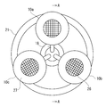
- FIG. 5 is an enlarged cross-sectional view taken along the line BB of FIG.
- FIG. 3A is a diagram showing an embodiment
- FIG. 3B is a diagram showing a flange portion without a flange portion.
- reference numeral 1 denotes a suction gripper for an organ such as a lung
- the suction gripper 1 includes a suction tube main body 2.
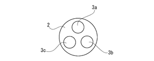
- the tube body 2 is a 3-lumen type tube in which three suction lumens 3a, 3b, and 3c are formed in the axial direction (FIG. 6).
- a metal protective pipe 5 is fitted to the front end of the tube body 2, a coated tube 6 is fitted to the protective pipe 5, and the protective pipe 5 and the coated tube 6 are fitted and integrated.
- the front end portion of the tube body 2 is inserted into the central boss portion 11 of the holding body 9 made of silicone rubber or flexible resin, and the concave portion 12 and the convex portion 13 provided at the rear end portion of the boss portion and the front end portion of the covering tube. It is connected and fixed by fitting.
- a plurality of annular recesses 15 are provided on the outer peripheral surface of the covering tube 6 in the axial direction to form uneven portions. 16 is a seal.
- the metal protective pipe 5 is made of stainless steel in this example, and the reason why the stainless steel protective pipe is provided is to prevent the tube body 2 from being crushed when grasping this portion with forceps in the treatment. .. Further, the reason why the annular recess 15 is provided on the outer peripheral surface of the covering tube 6 to form the uneven portion is to prevent slipping when grasping this portion with forceps.
- the outer peripheral surface of the tube main body 2 is not provided with a guide tube made of a metal pipe as in the previous application (Patent Document 1), but when it is easy to kink during use, it is appropriate. It may be provided. By doing so, kink is less likely to occur and it becomes possible to pull large organs. Further, when the guide tube is provided, it is also possible to separately cover the outer peripheral surface of the guide tube with a covering tube so as not to damage the living tissue during use.
- the central boss portion 11 is a portion that serves as a core portion of the holding body 9, and is therefore formed with a predetermined length in the axial direction.
- Three airway tubes 18 are axially communicated with the suction lumens 3a, 3b, and 3c through the central boss portion 11.
- the holding body 9 includes the central boss portion 11 described above, a plurality of suction cup mounting portions 20 projecting from the boss portion in the radial direction, and a ring portion 21 fixed to the tip end portion of the mounting portion.
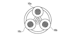
- a circular mounting hole 22 is bored in the suction cup mounting portion 20, and a plurality of suction cups 10a, 10b, and 10c (three in this embodiment) are inserted into the mounting holes and viewed from the side (three in this embodiment). In FIG. 2), they are arranged and attached at equal intervals in the circumferential direction. That is, the suction cups 10a, 10b, and 10c are arranged so that the lines connecting the centers of the suction cups form an equilateral triangle.
- a metal wire 21a made of stainless steel is embedded in the ring portion 21 to maintain its shape. However, although the metal wire 21a is embedded, the ring portion 21 has a certain degree of freedom in bending.
- the suction cup mounting portion 20 corresponds to a conventional dome member, but its height (length in the axial direction) is high because it is not shaped like a dome member but has a flat plate shape. There is no such thing as becoming. Therefore, even if it is placed in the thoracic cavity, there is no problem in handling the operation and processing.
- Each suction cup 10a, 10b, 10c has a cavity that expands from the attached end toward the open end, and the inner surface of the cavity has a small size for increasing the suction force.
- a plurality of protrusions 23 are provided. In this example, horizontally long round small protrusions 23 are provided at equal intervals in the circumferential direction.
- suction holes 25 are formed near the funnel-shaped side bottom portion, and one end of each of the above-mentioned airway tubes 18 is connected to each of these suction holes 25 in communication with each other. As described above, the other end of the airway tube 18 is connected to the suction lumens 3a, 3b, and 3c at the central boss portion 11 in communication with each other.
- the small protrusion 23 has a role of preventing the biological tissue adsorbed by the small protrusion from blocking the suction hole 25.
- Such a small protrusion 23 makes it possible to prevent a decrease in the suction area, and it is possible to increase the suction force in the suction cups 10a, 10b, 10c.
- the front of the lumen is a suction port.
- a mesh 26 made of polyester fiber or the like is attached to the cavity between the suction hole 25 and the small protrusion 23. By partitioning the lumen, such a mesh 26 can allow the organ to enter close to the suction hole 25 even when sucking a soft organ, and prevents the suction hole 25 from being blocked. Because.
- each suction cup 10a, 10b, 10c At the open end of each suction cup 10a, 10b, 10c, a flat plate-shaped flange portion 27 formed by bending inward at a substantially right angle from the edge is formed.
- the reason why the flange portion 27 is provided is to prevent the suction cups 10a, 10b, and 10c from being unable to follow due to the deformation of the organ and forming a gap, as will be described later.
- each suction cup portion 10a, 10b, 10c has an outer diameter of about 2 cm, and sucks an organ by applying a negative pressure of 20 to 50 cmHg from a suction device as a suction source (not shown) to grip, move, and fix the organ. It is possible.
- the central axes of the suction cups 10a, 10b, and 10c and the central axis of the central boss 11 of the holding body 9 are both parallel to the central axis of the tube body 2.
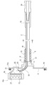
- a short tube 28 of 1 lumen type is connected to the rear end of the tube body 2 by communicating the suction lumen with the suction lumens 3a, 3b, 3c (FIG. 5).
- the tube 28 is connected to a connector 29 and an induction rod (not shown) that are connected to the aspirator.
- FIG. 5 only the suction cup 10a portion is shown, and the suction cups 10b and 10c portions are omitted.
- the holding bodies 9 such as the suction cups 10a, 10b, 10c and the suction cup mounting portion 20 are preferably formed of a transparent or translucent material in order to enhance visibility by the endoscope.
- a and B are trocars placed in a small incision
- C is the abdominal wall
- D is the lung as an example of an organ
- E is an endoscope
- F Indicates a small incision
- G indicates an electric knife
- H indicates forceps.
- trocars A and B are pierced into the abdominal wall C and inserted toward the lung D in the body cavity and placed. Then, the endoscope E is inserted into one of the trocars A, and the suction gripper 1 is reached through the small incision F formed in the abdominal wall C with a size of about 40 to 50 mm, and the tube body 2 reaches the middle thereof. Insert to the position. At the time of this insertion, since the small incision F is about 40 to 50 mm and the ring portion 21 of the holding body 9 is about 50 mm, the outer peripheral edge of the ring portion 21 is caught by the small incision F of the abdominal wall C and is inserted. Although a problem is expected, the ring portion 21 is made of silicone rubber or a flexible resin and can be reduced in diameter together with the suction cups 10a, 10b, and 10c, so that the insertion can be easily performed.
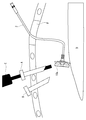
- suction gripper 1 When the suction gripper 1 is inserted and the suction cups 10a, 10b, and 10c are guided to a position where the suction cups 10a, 10b, and 10c approach the lung D and easily suck the lung D as shown in FIG.
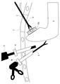
- suction cup 10a, 10b, and 10c When a connected suction device (not shown) is operated to apply negative pressure, suction cups 10a, 10b, and 10c suck the soft surface of lung D as shown in FIG.
- the suction hole 25 In this suction gripping state, the suction hole 25 is not blocked by the small protrusions 23 or the mesh 26, so that a good suction state is maintained.
- the suction gripper 1 held by the forceps H so as to sandwich the outer peripheral surface of the covering tube 6 is pulled back to the outside to adjust the degree of insertion.
- the back side of the lung D for example, where the affected part is located, is brought to a position observable by the endoscope E, and under the observation by the endoscope, the affected part is excised with an electric knife G inserted from another trocar B. I will perform the technique.
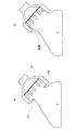
- the flange portion 27 suppresses the deformation of the sucked lung D. Therefore, as shown in FIG. 10 (A), the lung sucked by the suction cup 10a. D is sucked in an orderly and stable posture without creating a gap near the suction port, and then an operation such as excision is performed. Therefore, the lung tissue sucked into the suction cup is in a state of being tightened in the lumen, and the deformation of the lung when the lung is inverted can be suppressed. Therefore, the suction cup is hard to come off from the lung D, and its slippage can be prevented.
- the lung D After the treatment, when the operation of the suction device is stopped and the suction grip on the surface of the lung D by the suction cups 10a, 10b, 10c is stopped, the lung D returns to the original position where the affected part is on the back side. At the same time, the suction gripper 1 is pulled out from the small incision opening F. At this time, if the holding body 9 is flat and hard, it is caught in the small incision opening F of the abdominal wall C and is difficult to remove, but the holding body Since No. 9 is made of a ring-shaped relatively soft resin as described above, the suction cups 10a, 10b, and 10c can be easily removed by reducing the diameter and reducing the resistance. Further, it is also possible to perform an operation of excluding (pushing) an organ with this suction gripper 1, and since the holding body 9 is ring-shaped and has no corners, it is possible to prevent damage to living tissue during expulsion. it can.
- the ring-shaped holding body 9 can be reduced in diameter by using the suction gripper 1, it can be smoothly and easily inserted into the small incision opening F and removed from the small incision opening F without any trouble. be able to. Further, since the suction force of the suction cups 10a, 10b, 10c does not decrease, it is possible to prevent the suction cups 10a, 10b, 10c from slipping off, and even if the organ is soft and easily deformed, the lifting and expulsion operations can be performed reliably. Can be done. Moreover, since the retainer 9 is ring-shaped and has no corners, it is possible to prevent damage to the living tissue during exclusion.
- the height of the suction grip portion can be lowered by changing the conventional dome-shaped member to the ring-shaped holding body 9 as described above. Therefore, it is possible to improve the maneuverability of operations and processing, secure the field of view of the endoscope, and secure the surgical space. Moreover, since the metal wire is embedded in the ring portion 21 of the holding body 9, the shape of the ring portion can be maintained. Further, since the disk-shaped flange portion 27 is provided on the opening edge of the suction cup, it is possible to prevent a gap from the suction cup from being generated, and the suction fixing can be stably maintained.
- the ring-shaped holding body 9 shown in the embodiment is only a preferable example, and does not exclude other modified examples and the like.
- other members are merely examples, and may have shapes and structures other than those shown in the drawings. It goes without saying that the design of the details of the present invention can be arbitrarily changed or modified as long as it is within the scope of claims.
- Suction gripper 2 Suction tube body 3a, 3b, 3c Suction lumen 5
- Metal protective pipe 6 Covered tube 9
- Ring-shaped holder 10a, 10b, 10c Sucker 11 Central boss 18
- Airway tube 15 Circular recess 20
- Sucker mounting part 21 Ring part 23
- Small protrusion 25 Suction hole 26
- Mesh 27 Flange part 29
- Connection connector A, B Troker C Abdominal wall
Landscapes
- Health & Medical Sciences (AREA)
- Surgery (AREA)
- Life Sciences & Earth Sciences (AREA)
- Engineering & Computer Science (AREA)
- Molecular Biology (AREA)
- Biomedical Technology (AREA)
- Heart & Thoracic Surgery (AREA)
- Medical Informatics (AREA)
- Nuclear Medicine, Radiotherapy & Molecular Imaging (AREA)
- Animal Behavior & Ethology (AREA)
- General Health & Medical Sciences (AREA)
- Public Health (AREA)
- Veterinary Medicine (AREA)
- Robotics (AREA)
- Mechanical Engineering (AREA)
- Surgical Instruments (AREA)
- Endoscopes (AREA)
Abstract
この発明は、吸引把持具の高さを低くすることができるとともに、内視鏡の視野の確保、手術スペースの確保ができ、吸盤が臓器の変形にも対応して外れにくい臓器吸引把持具を提供することを目的とする。 この発明の臓器吸引把持具(1)は、吸引チューブ本体(2)を備え、このチューブ本体の前端部に複数個の臓器吸引用吸盤(10a,10b,10c)が設けられ、これら吸盤の吸引力により臓器を吸引し、挙上して把持する。前記複数個の吸盤がチューブ本体の前端部に設けたリング状の保持体(9)で保持され、前記吸盤の開放側の端部に環状のフランジ部(27)が設けられている。
Description
この発明は、臓器吸引把持具に関し、さらに詳しくは、例えば内視鏡で外科手術を行う際に肺などの臓器の表面を吸引することにより挙上把持して手術を行い易くする技術に係るものである。
外科手術では、患部の処置をし易くするため視野の邪魔となる臓器の挙上・圧排等の操作が必須である。開胸・開腹手術では術者の手や外科用スタビライザーなどの器具を使用し挙上しているが、低侵襲手術である内視鏡による外科手術では、小さな切開創にトロカーを留置し、トロカーを介して手術器具を挿入するので大型の器具は体腔内に挿入できず、鉗子等を使用して挙上を行っている。
ところで、出願人は、先に特開2017-202093号公報(特許文献1)を提案した。しかしながら、この特許文献1の臓器吸引把持具は、実際に使用したところ、限られた空間(胸腔内)では、ドーム状部材があることもあってその高さ(軸方向の長さ)が高すぎてしまい、操作や処理等の取り回しが悪いという問題があった。
また、複数個の吸盤がその背後からドーム状部材で覆われる構成であるため、内視鏡の視野が遮られてしまい、手術を行うスペースが狭くなるという問題があった。
さらに、肺を吸引し保持(特に横方向の牽引)したところ、肺が柔軟で変形しやすく、その変化に吸盤が追随して対応することができず、隙間ができて外れ、滑脱してしまうといった問題もあった。
そこで、この発明は、前記のような従来の問題点を解決し、吸引把持具の高さを低くすることができるとともに、内視鏡の視野の確保、手術スペースの確保ができ、吸盤が臓器の変形にも対応して外れにくい臓器吸引把持具を提供することを目的とする。
前記課題を解決するために、請求項1に記載の発明は、吸引チューブ本体を備え、このチューブ本体の前端部に複数個の臓器吸引用吸盤が設けられ、これら吸盤の吸引力により臓器を吸引し、挙上して把持するための臓器吸引把持具において、前記複数個の吸盤がチューブ本体の前端部に設けたリング状の保持体で保持され、前記吸盤の開放側の端部に環状のフランジ部が設けられていることを特徴とする。
請求項2に記載の発明は、請求項1において、保持体は、シリコーンゴム又は柔軟性樹脂からなり、中央ボス部と、該ボス部から放射方向に複数個、張り出して設けられた吸盤取付部と、該各取付部の先端部を結ぶように固定されたリング部と、を有し、前記リング部の内部には金属ワイヤが埋設されている。請求項3に記載の発明は、請求項1又は2において、保持体は、吸盤取付部に設けた取付穴で吸盤の開放側と反対側の端部を保持するようになっている。
請求項4に記載の発明は、請求項1において、フランジ部は、吸盤の開放端縁から内向きに屈曲して形成されている。請求項5に記載の発明は、請求項1において、吸引チューブ本体の前端部は、保護用パイプによって被覆されたうえ前記保持体の中央ボス部と接続されている。
請求項6に記載の発明は、請求項5において、保護用パイプには被覆チューブが嵌合され、その外周面には凹凸部が設けられている。
請求項7に記載の発明は、請求項1において、吸盤は、前記保持体に、各吸盤の中心間を結ぶ線が正三角形を形成するように配置された、3個の吸盤からなっている。請求項8に記載の発明は、請求項1において、吸盤は、その中心軸線がチューブ本体の中心軸線と平行になっている。
この発明は、前記のようであって、請求項1に記載の発明によれば、臓器吸引把持具において、複数個の吸盤をチューブ本体の前端部に設けたリング状の保持体で保持したので、従来のドーム状部材の奏する作用効果を期待できるのは勿論のこと、ドーム状部材に代えてリング状の保持体で吸盤を保持する構成としたので、その高さを低くすることができ、操作や処理等の取り回しがよくなる。しかも、ドーム状部材に比し、内視鏡の視野の確保、手術スペースの確保がよくなる。また、吸盤の開放側の端部に環状のフランジ部を設けたので、柔軟な肺(臓器)であっても、変形を抑制し、吸盤が外れにくいものとなり、その滑脱を防止することができる。
請求項2に記載の発明によれば、シリコーンゴム又は柔軟性樹脂からなる保持体のリング部内に埋設された金属ワイヤによって保持体の形態が保たれる。請求項3に記載の発明によれば、吸盤の保持が容易になる。請求項4に記載の発明によれば、内向きに屈曲したフランジ部によって臓器の変形に伴う吸盤の開放側端部の隙間発生をなくして臓器の変形防止をより効率的に行える。
請求項5に記載の発明によれば、チューブ本体と保持体との接続を容易に行うことができる。請求項6に記載の発明によれば、鉗子での掴持を確実に行える。請求項7に記載の発明によれば、3個の吸盤をバランスよく配置することが可能となって、吸引力の均等化が図れる。請求項8に記載の発明によれば、チューブ本体に対して、吸盤及び保持体が同じ方向を向いて取り付けることが可能となり、取り付け作業の能率アップを図り、製作の作業性を向上することができる。
以下、図面を参照しながら実施の形態に係る臓器吸引把持具について説明する。
図1~6において、1は肺など臓器の吸引把持具であり、この吸引把持具1は、吸引チューブ本体2を備えている。このチューブ本体2は、軸方向に3つの吸引ルーメン3a,3b,3cが形成された3ルーメンタイプのチューブとなっている(図6)。チューブ本体2の前端部には金属製保護パイプ5が嵌合され、さらに該保護パイプ5には被覆チューブ6が嵌合され、これら保護パイプ5と被覆チューブ6が嵌合されて一体となったチューブ本体2の前端部は、シリコーンゴム又は柔軟性樹脂からなる保持体9の中央ボス部11と、該ボス部の後端部と被覆チューブの前端部に設けた凹部12と凸部13の差し込み嵌合により連結固定されている。被覆チューブ6の外周面には環状の凹部15が複数個、軸方向に設けられ、凹凸部を形成している。16は目止めである。
金属製保護パイプ5は、この例ではステンレスからなっており、このステンレス製の保護パイプを設けたのは、施術において鉗子でこの部分を掴むときにチューブ本体2が潰れるのを防止するためである。また、被覆チューブ6の外周面に環状の凹部15を設けて凹凸部を形成したのは、鉗子でこの部分を掴むときに滑らないようにするためである。
この実施の形態ではチューブ本体2の外周面には先願(特許文献1)のような金属製のパイプからなるガイド管を設けていないが、使用に際しキンクし易いとき等の場合は、適宜に設けてもよい。そうすれば、キンクが生じにくくなって大きな臓器の牽引も可能となる。また、ガイド管を設ける場合はその外周面を別途被覆チューブで覆い、使用に際し生体組織を損傷することが無いようにすることも可能である。
中央ボス部11は、保持体9の芯部となる部分であり、そのため軸方向に所定の長さをもって形成されている。このような中央ボス部11には軸方向に3本の気道チューブ18が吸引ルーメン3a,3b,3cと連通して通っている。
保持体9は、前記した中央ボス部11と、該ボス部から放射方向に複数個、張り出して設けられた吸盤取付部20と、該取付部の先端部に固定されたリング部21と、を有している。吸盤取付部20には円形の取付穴22が穿設され、該取付穴には複数個(この実施例では3個)の吸盤10a,10b,10cが、その端部を嵌挿して側面視(図2)で円周方向に等間隔で配置されて取り付けられている。すなわち、吸盤10a,10b,10cは、各吸盤の中心間を結ぶ線が正三角形を形成するように配置されている。リング部21には形態保持のためにステンレスからなる金属ワイヤ21aが埋設されている。ただ金属ワイヤ21aが埋設されているとはいえ、リング部21はある程度の屈曲できる自由度があるようになっている。
吸盤取付部20は、従前のドーム部材に相当するものであるが、ドーム部材のような形状になっておらず、平板状になっているため、その高さ(軸方向の長さ)が高くなるようなことがない。そのため、胸腔内に入れても、その操作や処理等の取り回しで支障になることがない。
各吸盤10a,10b,10cは、その取付られた端部から開放側の端部に向けて拡開状となった内腔を有し、この内腔の内面には吸着力アップのための小突起23が複数個設けられている。この例では横長丸形の小突起23が円周方向に均等の間隔で設けられている。また、漏斗状になった側底部近くには吸引孔25が形成され、これら吸引孔25にはそれぞれ前記した各気道チューブ18の一端が連通して接続されている。気道チューブ18の他端は前記したように中央ボス部11において各吸引ルーメン3a,3b,3cと連通して接続されている。小突起23は前記のように吸着力アップのほか、該小突起によって吸着された生体組織が吸引孔25を閉塞しないようにする役割をもっている。このような小突起23により吸引面積の減少を防ぐことが可能となり、吸盤10a,10b,10cにおける吸引力のアップを図ることができる。内腔の前方は吸引口となっている。
また、吸引孔25と小突起23の間の内腔にはポリエステル繊維等で製作したメッシュ26が張り付けられている。このようなメッシュ26を設けたのは、内腔を仕切ることにより、軟らかい臓器を吸引する場合でも吸引孔25のある近くまで臓器を入り込ませることができ、かつ吸引孔25を塞ぐのを阻止するためである。
各吸盤10a,10b,10cの開放端には端縁から内向きにほぼ直角に屈曲して形成された平板状のフランジ部27が形成されている。このようなフランジ部27を設けたのは、後述するように臓器の変形により吸盤10a,10b,10cが追随できず、隙間が生ずるのを防止するためである。
また、各吸盤部10a,10b,10cは、外径が2cm程度からなり、図示しない吸引源としての吸引器から20~50cmHgの陰圧をかけることで臓器を吸引し、把持・移動・固定することが可能になっている。そして、吸盤部10a,10b,10cの中心軸線、保持体9の中央ボス部11の中心軸線は、ともにチューブ本体2の中心軸線と平行になっている。
チューブ本体2の後端部には1ルーメンタイプの短いチューブ28がその吸引ルーメンを吸引ルーメン3a,3b,3cと連通して接続されている(図5)。このチューブ28には使用に際して、前記吸引器と接続する接続コネクタ29や誘導ロッド(図示せず)が接続される。なお、図5では吸盤10a部分のみ示し、吸盤10b,10c部分は省略している。
なお、各吸盤10a,10b,10cや吸盤取付部20などの保持体9は、内視鏡による視認性を高めるために透明又は半透明の材質から形成することが好ましい。
次に、図7~10を参照して使用方法について説明する。まず各図においてアルファベット文字で表記した各部等の符号について説明すると、A,Bは小さな切開創に留置されたトロカー、Cは腹壁、Dは臓器の一例としての肺、Eは内視鏡、Fは小切開口、Gは電気メス、Hは鉗子を示す。
使用に際しては、図7~8に示すようにトロカーA,Bを腹壁Cに突き刺して体腔内の肺Dに向けて挿入して留置する。そのうえで、一方のトロカーAに内視鏡Eを挿入するとともに、腹壁Cに40~50mm程度の大きさに形成された小切開口Fから吸引把持具1を、チューブ本体2がその中程に達する位置まで挿入する。この挿入に際し、小切開口Fが40~50mm程度で、保持体9のリング部21が50mm程度であるため、そのままではリング部21の外周縁が腹壁Cの小切開口Fに引っかかって挿入に支障が予測されるものの、リング部21がシリコーンゴム又は柔軟性樹脂からなり吸盤10a,10b,10cとともに縮径可能なので挿入は容易に行える。
そして、吸引把持具1の挿入を進めて、図8に示すように吸盤10a,10b,10cが肺Dに接近して肺Dを吸引し易い位置に誘導されたところで、別途、接続コネクタ29に接続する図示しない吸引器を作動して陰圧をかけると、図9に示すように吸盤10a,10b,10cが肺Dの軟らかい表面を吸引する。この吸引把持状態では吸引孔25が小突起23やメッシュ26によって塞がれることがないから良好な吸引状態が持続する。そして、この吸盤10a,10b,10cによる吸引がされた状態で、鉗子Hで被覆チューブ6の外周面を挟むように掴持した吸引把持具1を外部に引き戻したりしてその挿入度を加減することにより肺Dの、例えば患部がある裏側を内視鏡Eで観察可能な位置にもたらし、該内視鏡による観察の下で、別のトロカーBから挿入する電気メスGで患部に対する切除等の術を施すことになる。
吸盤10a,10b,10cが肺Dの軟らかい表面を吸引する際に、フランジ部27が吸引される肺Dの変形を抑制するので、図10(A)に示すように吸盤10aに吸引された肺Dは吸引口付近での隙間を生ずることなく整然と安定した姿勢で吸引され、その後の切除等の術が施されることになる。そのため、吸盤内に吸い込まれた肺の組織が、内腔内で締めこまれた状態となり、肺を反転させる際の肺の変形を抑制させることができる。そのため、肺Dから吸盤が外れにくいものとなり、その滑脱を防止することができる。
一方、このようなフランジ部27がない吸盤で吸引すると、図10(B)に示すように肺Dの変形に吸盤10aが追随できず、吸引口付近で隙間ができてしまい、安定した姿勢で吸引ができにくく、外れやすいものとなる。したがって、フランジ部27の有無が吸盤による吸引の差に歴然とあらわれる。前記のことにつき、試作品で、吸盤の吸引による牽引試験を行ったところ、図10(A)に示すフランジ部27のある吸盤10a,10b,10cのほうが、水平方向への牽引であっても、牽引力が大幅に向上したことがわかった。
施術後、前記吸引器の作動を停止し、吸盤10a,10b,10cによる肺Dの表面の吸引把持を止めると、肺Dは患部が裏側になる元の位置に戻る。それととともに、吸引把持具1を小切開口Fから抜き出すが、この際にも保持体9が平面状の硬いものであると腹壁Cの小切開口Fに引っかかってしまい抜去しにくいが、保持体9は前記のようにリング状の比較的軟らかい樹脂からなっているので、吸盤10a,10b,10cともども縮径して抵抗を低くして容易に抜去することができる。また、この吸引把持具1で、臓器を圧排(押し込む)操作をすることも可能であり、保持体9がリング状であって角が無いため、圧排する際に生体組織が損傷するのを防止できる。
前記のように、吸引把持具1を用いれば、リング状となった保持体9が縮径可能なので、小切開口Fへの挿入や小切開口Fからの抜去も支障なく円滑かつ容易に行うことができる。また、吸盤10a,10b,10cによる吸引力も低下しないから、吸盤10a,10b,10cの滑脱を防止することができ、柔らかく変形し易い臓器であっても確実に挙上・圧排の操作が行うことができる。しかも、保持体9がリング状であって角が無いため、圧排する際に生体組織が損傷するのを防止できる。
この実施の形態では前記のように従前のドーム状部材をリング状の保持体9に変更したことで、吸引把持部の高さを低くすることができる。そのため、操作や処理等の取り回しが良くなるとともに、内視鏡の視野の確保、手術スペースの確保ができる。しかも、保持体9のリング部21に金属ワイヤを埋設しているため、リング部の形状を保持することができる。また、吸盤の開口端縁に円盤状のフランジ部27を設けているので、吸盤との隙間が生じるのを防止することができ、吸引固定を安定的に維持させることができる。この試作品でも、前記したように牽引試験を行ったところ、水平方向への牽引であっても、牽引力が大幅に向上し、吸盤内に吸い込まれた組織が、円盤部で締めこまれた状態となり、肺を反転させる際の肺の変形を抑制させることができ。また、吸盤も外れにくいものとなって、その滑脱を防止することができる。
実施の形態で示すリング状の保持体9は、好ましい一例にすぎず、他の変形例等を排除するものではない。また、その他の部材も一例を示したにすぎず、図示したもの以外の形状、構造としてもよい。この発明は特許請求の範囲に記載した範囲内であれば細部の設計等は任意に変更、修正が可能であることは言うまでもない。
1 吸引把持具
2 吸引チューブ本体
3a,3b,3c 吸引ルーメン
5 金属製保護パイプ
6 被覆チューブ
9 リング状の保持体
10a,10b,10c 吸盤
11 中央ボス部
18 気道チューブ
15 環状の凹部
20 吸盤取付部
21 リング部
23 小突起
25 吸引孔
26 メッシュ
27 フランジ部
29 接続コネクタ
A,B トロカー
C 腹壁
D 肺(臓器)
E 内視鏡
F 小切開口
G 電気メス
H 鉗子
2 吸引チューブ本体
3a,3b,3c 吸引ルーメン
5 金属製保護パイプ
6 被覆チューブ
9 リング状の保持体
10a,10b,10c 吸盤
11 中央ボス部
18 気道チューブ
15 環状の凹部
20 吸盤取付部
21 リング部
23 小突起
25 吸引孔
26 メッシュ
27 フランジ部
29 接続コネクタ
A,B トロカー
C 腹壁
D 肺(臓器)
E 内視鏡
F 小切開口
G 電気メス
H 鉗子
Claims (8)
- 吸引チューブ本体を備え、このチューブ本体の前端部に複数個の臓器吸引用吸盤が設けられ、これら吸盤の吸引力により臓器を吸引し、挙上して把持するための臓器吸引把持具において、
前記複数個の吸盤がチューブ本体の前端部に設けたリング状の保持体で保持され、前記吸盤の開放側の端部に環状のフランジ部が設けられていることを特徴とする臓器吸引把持具。 - 保持体は、シリコーンゴム又は柔軟性樹脂からなり、中央ボス部と、該ボス部から放射方向に複数個、張り出して設けられた吸盤取付部と、該各取付部の先端部を結ぶように固定されたリング部と、を有し、前記リング部の内部には金属ワイヤが埋設されている請求項1に記載の臓器吸引把持具。
- 保持体は、吸盤取付部に設けた取付穴で吸盤の開放側と反対側の端部を保持するようになっている請求項1又は2に記載の臓器吸引把持具。
- フランジ部は、吸盤の開放端縁から内向きに屈曲して形成されている請求項1に記載の臓器吸引把持具。
- 吸引チューブ本体の前端部は、保護用パイプによって被覆されたうえ保持体の中央ボス部と接続されている請求項1に記載の臓器吸引把持具。
- 保護用パイプには被覆チューブが嵌合され、その外周面には凹凸部が設けられている請求項5に記載の臓器吸引把持具。
- 吸盤は、各吸盤の中心間を結ぶ線が正三角形を形成するように保持体に配置された、3個の吸盤からなる請求項1に記載の臓器吸引把持具。
- 吸盤は、その中心軸線がチューブ本体の中心軸線と平行になっている請求項1に記載の臓器吸引把持具。
Priority Applications (2)
| Application Number | Priority Date | Filing Date | Title |
|---|---|---|---|
| CN202080024693.1A CN113677276B (zh) | 2019-05-16 | 2020-04-23 | 脏器吸引把持具 |
| US17/611,254 US12262907B2 (en) | 2019-05-16 | 2020-04-23 | Organ sucking and grasping tool |
Applications Claiming Priority (2)
| Application Number | Priority Date | Filing Date | Title |
|---|---|---|---|
| JP2019092810A JP6941322B2 (ja) | 2019-05-16 | 2019-05-16 | 臓器吸引把持具 |
| JP2019-092810 | 2019-05-16 |
Publications (1)
| Publication Number | Publication Date |
|---|---|
| WO2020230575A1 true WO2020230575A1 (ja) | 2020-11-19 |
Family
ID=73221108
Family Applications (1)
| Application Number | Title | Priority Date | Filing Date |
|---|---|---|---|
| PCT/JP2020/017484 Ceased WO2020230575A1 (ja) | 2019-05-16 | 2020-04-23 | 臓器吸引把持具 |
Country Status (5)
| Country | Link |
|---|---|
| US (1) | US12262907B2 (ja) |
| JP (1) | JP6941322B2 (ja) |
| CN (1) | CN113677276B (ja) |
| TW (1) | TWI745954B (ja) |
| WO (1) | WO2020230575A1 (ja) |
Families Citing this family (3)
| Publication number | Priority date | Publication date | Assignee | Title |
|---|---|---|---|---|
| US12533149B2 (en) * | 2021-05-27 | 2026-01-27 | Jason Cohen | Tissue engaging surgical tool |
| CN115349812B (zh) * | 2022-09-23 | 2026-07-21 | 深圳市资福医疗技术有限公司 | 一种牵引装置、控制方法及胶囊内窥镜 |
| CN116211404B (zh) * | 2022-11-16 | 2025-11-11 | 中国人民解放军总医院第三医学中心 | 一种腹腔镜肾脏抓持器 |
Citations (4)
| Publication number | Priority date | Publication date | Assignee | Title |
|---|---|---|---|---|
| JP2005515014A (ja) * | 2002-01-23 | 2005-05-26 | アイオテック,インコーポレイティド | 臓器組織の操作装置および方法 |
| JP4406716B2 (ja) * | 2001-01-13 | 2010-02-03 | メドトロニック,インコーポレイテッド | 臓器を位置決めする方法及び装置 |
| JP4556949B2 (ja) * | 2004-10-14 | 2010-10-06 | 住友ベークライト株式会社 | 冠状動脈バイパス術用処置具 |
| JP2017202093A (ja) * | 2016-05-11 | 2017-11-16 | 国立大学法人京都大学 | 臓器吸引把持具 |
Family Cites Families (14)
| Publication number | Priority date | Publication date | Assignee | Title |
|---|---|---|---|---|
| US6852075B1 (en) * | 1996-02-20 | 2005-02-08 | Cardiothoracic Systems, Inc. | Surgical devices for imposing a negative pressure to stabilize cardiac tissue during surgery |
| US6506149B2 (en) | 1999-09-07 | 2003-01-14 | Origin Medsystems, Inc. | Organ manipulator having suction member supported with freedom to move relative to its support |
| US6641604B1 (en) * | 2000-02-11 | 2003-11-04 | Iotek, Inc. | Devices and method for manipulation of organ tissue |
| US6663622B1 (en) * | 2000-02-11 | 2003-12-16 | Iotek, Inc. | Surgical devices and methods for use in tissue ablation procedures |
| US7479104B2 (en) * | 2003-07-08 | 2009-01-20 | Maquet Cardiovascular, Llc | Organ manipulator apparatus |
| US7097612B2 (en) * | 2003-07-29 | 2006-08-29 | Endoscopic Technologies, Inc. | Tissue positioner |
| JP4527462B2 (ja) * | 2004-07-23 | 2010-08-18 | 双信電機株式会社 | 電子部品 |
| CN101588760B (zh) * | 2007-01-26 | 2012-05-09 | 奥林巴斯医疗株式会社 | 把持装置及把持器具 |
| US20090326518A1 (en) * | 2008-02-14 | 2009-12-31 | Rabin Barry H | Devices and methods for manipulating tissue |
| JP2010029382A (ja) * | 2008-07-28 | 2010-02-12 | Olympus Medical Systems Corp | 内視鏡挿入補助具及び内視鏡装置 |
| KR101136304B1 (ko) | 2009-08-13 | 2012-04-19 | 국립암센터 | 수술용 견인기구 |
| KR101230142B1 (ko) * | 2010-10-20 | 2013-02-05 | 이영삼 | 심장 안정화 장치 |
| CN203029293U (zh) * | 2013-01-19 | 2013-07-03 | 苏洪凯 | 脏器负压牵引器 |
| US9955986B2 (en) * | 2015-10-30 | 2018-05-01 | Auris Surgical Robotics, Inc. | Basket apparatus |
-
2019
- 2019-05-16 JP JP2019092810A patent/JP6941322B2/ja active Active
-
2020
- 2020-04-23 WO PCT/JP2020/017484 patent/WO2020230575A1/ja not_active Ceased
- 2020-04-23 US US17/611,254 patent/US12262907B2/en active Active
- 2020-04-23 CN CN202080024693.1A patent/CN113677276B/zh active Active
- 2020-05-06 TW TW109115050A patent/TWI745954B/zh active
Patent Citations (4)
| Publication number | Priority date | Publication date | Assignee | Title |
|---|---|---|---|---|
| JP4406716B2 (ja) * | 2001-01-13 | 2010-02-03 | メドトロニック,インコーポレイテッド | 臓器を位置決めする方法及び装置 |
| JP2005515014A (ja) * | 2002-01-23 | 2005-05-26 | アイオテック,インコーポレイティド | 臓器組織の操作装置および方法 |
| JP4556949B2 (ja) * | 2004-10-14 | 2010-10-06 | 住友ベークライト株式会社 | 冠状動脈バイパス術用処置具 |
| JP2017202093A (ja) * | 2016-05-11 | 2017-11-16 | 国立大学法人京都大学 | 臓器吸引把持具 |
Also Published As
| Publication number | Publication date |
|---|---|
| CN113677276A (zh) | 2021-11-19 |
| JP6941322B2 (ja) | 2021-09-29 |
| CN113677276B (zh) | 2024-09-20 |
| JP2020185269A (ja) | 2020-11-19 |
| US20220226011A1 (en) | 2022-07-21 |
| US12262907B2 (en) | 2025-04-01 |
| TW202042753A (zh) | 2020-12-01 |
| TWI745954B (zh) | 2021-11-11 |
Similar Documents
| Publication | Publication Date | Title |
|---|---|---|
| JP4701164B2 (ja) | 手指補助下腹腔鏡手術用アクセスデバイス | |
| US7097612B2 (en) | Tissue positioner | |
| JP2022002734A (ja) | 医療器具を搬送する装置及び方法 | |
| JP6941322B2 (ja) | 臓器吸引把持具 | |
| US20110230706A1 (en) | Surgical manipulator | |
| US20030139646A1 (en) | Devices and methods for manipulation of organ tissue | |
| JPH09187415A (ja) | 内視鏡用フード | |
| WO2020153006A1 (ja) | オーバーチューブ | |
| JP2017202093A (ja) | 臓器吸引把持具 | |
| JP4602580B2 (ja) | 湾曲圧排具 | |
| AU2024287234B2 (en) | Capture-tool for manipulating and entubulating nerves | |
| JP2024022727A (ja) | 胸腔鏡下手術用ポート | |
| US11832995B2 (en) | Graspable surgical device | |
| JP2010263959A (ja) | 外把持ツール | |
| US20090187195A1 (en) | Foreign object extractor | |
| HK40062166A (en) | Organ suctioning and gripping tool | |
| HK40062166B (en) | Organ suctioning and gripping tool | |
| EP2884919A2 (en) | Surgical device | |
| WO2019229874A1 (ja) | 粘膜拳上器具および粘膜拳上方法 | |
| JP2014104186A (ja) | 内視鏡挿入補助具 | |
| JP2008259554A (ja) | 組織の挙上システム並びに留置具 | |
| US12370090B2 (en) | Narrow-orifice foreign body extraction device | |
| CN111419165A (zh) | 单孔腹腔镜胆道镜鞘管 | |
| JP2011161130A (ja) | 冠状動脈バイパス術用処置具 | |
| CN216167731U (zh) | 一种用于腹腔镜手术的双球囊穿刺器 |
Legal Events
| Date | Code | Title | Description |
|---|---|---|---|
| 121 | Ep: the epo has been informed by wipo that ep was designated in this application |
Ref document number: 20805826 Country of ref document: EP Kind code of ref document: A1 |
|
| NENP | Non-entry into the national phase |
Ref country code: DE |
|
| 122 | Ep: pct application non-entry in european phase |
Ref document number: 20805826 Country of ref document: EP Kind code of ref document: A1 |
|
| WWG | Wipo information: grant in national office |
Ref document number: 17611254 Country of ref document: US |