WO2020230574A1 - 流量制御装置、流量制御方法、流量制御装置の制御プログラム - Google Patents
流量制御装置、流量制御方法、流量制御装置の制御プログラム Download PDFInfo
- Publication number
- WO2020230574A1 WO2020230574A1 PCT/JP2020/017480 JP2020017480W WO2020230574A1 WO 2020230574 A1 WO2020230574 A1 WO 2020230574A1 JP 2020017480 W JP2020017480 W JP 2020017480W WO 2020230574 A1 WO2020230574 A1 WO 2020230574A1
- Authority
- WO
- WIPO (PCT)
- Prior art keywords
- flow rate
- sensor
- flow
- control device
- filter
- Prior art date
Links
- 238000000034 method Methods 0.000 title claims description 12
- 230000004044 response Effects 0.000 claims abstract description 72
- 239000012530 fluid Substances 0.000 claims abstract description 32
- 238000005259 measurement Methods 0.000 claims abstract description 12
- 238000013016 damping Methods 0.000 claims description 2
- 238000011144 upstream manufacturing Methods 0.000 description 11
- 238000006243 chemical reaction Methods 0.000 description 4
- 238000010586 diagram Methods 0.000 description 4
- 238000005516 engineering process Methods 0.000 description 4
- 230000003321 amplification Effects 0.000 description 2
- 230000002238 attenuated effect Effects 0.000 description 2
- 238000004590 computer program Methods 0.000 description 2
- 230000003111 delayed effect Effects 0.000 description 2
- 238000003199 nucleic acid amplification method Methods 0.000 description 2
- 230000001052 transient effect Effects 0.000 description 2
- 238000013459 approach Methods 0.000 description 1
- 238000001514 detection method Methods 0.000 description 1
- 238000005530 etching Methods 0.000 description 1
- 239000002184 metal Substances 0.000 description 1
- 230000002194 synthesizing effect Effects 0.000 description 1
Images


Classifications
-
- G—PHYSICS
- G05—CONTROLLING; REGULATING
- G05D—SYSTEMS FOR CONTROLLING OR REGULATING NON-ELECTRIC VARIABLES
- G05D7/00—Control of flow
- G05D7/06—Control of flow characterised by the use of electric means
-
- G—PHYSICS
- G01—MEASURING; TESTING
- G01F—MEASURING VOLUME, VOLUME FLOW, MASS FLOW OR LIQUID LEVEL; METERING BY VOLUME
- G01F1/00—Measuring the volume flow or mass flow of fluid or fluent solid material wherein the fluid passes through a meter in a continuous flow
- G01F1/68—Measuring the volume flow or mass flow of fluid or fluent solid material wherein the fluid passes through a meter in a continuous flow by using thermal effects
- G01F1/696—Circuits therefor, e.g. constant-current flow meters
- G01F1/698—Feedback or rebalancing circuits, e.g. self heated constant temperature flowmeters
-
- G—PHYSICS
- G05—CONTROLLING; REGULATING
- G05D—SYSTEMS FOR CONTROLLING OR REGULATING NON-ELECTRIC VARIABLES
- G05D7/00—Control of flow
- G05D7/06—Control of flow characterised by the use of electric means
- G05D7/0617—Control of flow characterised by the use of electric means specially adapted for fluid materials
- G05D7/0629—Control of flow characterised by the use of electric means specially adapted for fluid materials characterised by the type of regulator means
- G05D7/0635—Control of flow characterised by the use of electric means specially adapted for fluid materials characterised by the type of regulator means by action on throttling means
-
- G—PHYSICS
- G01—MEASURING; TESTING
- G01F—MEASURING VOLUME, VOLUME FLOW, MASS FLOW OR LIQUID LEVEL; METERING BY VOLUME
- G01F1/00—Measuring the volume flow or mass flow of fluid or fluent solid material wherein the fluid passes through a meter in a continuous flow
- G01F1/68—Measuring the volume flow or mass flow of fluid or fluent solid material wherein the fluid passes through a meter in a continuous flow by using thermal effects
- G01F1/684—Structural arrangements; Mounting of elements, e.g. in relation to fluid flow
- G01F1/6842—Structural arrangements; Mounting of elements, e.g. in relation to fluid flow with means for influencing the fluid flow
-
- G—PHYSICS
- G01—MEASURING; TESTING
- G01F—MEASURING VOLUME, VOLUME FLOW, MASS FLOW OR LIQUID LEVEL; METERING BY VOLUME
- G01F15/00—Details of, or accessories for, apparatus of groups G01F1/00 - G01F13/00 insofar as such details or appliances are not adapted to particular types of such apparatus
- G01F15/005—Valves
-
- G—PHYSICS
- G01—MEASURING; TESTING
- G01F—MEASURING VOLUME, VOLUME FLOW, MASS FLOW OR LIQUID LEVEL; METERING BY VOLUME
- G01F5/00—Measuring a proportion of the volume flow
-
- G—PHYSICS
- G05—CONTROLLING; REGULATING
- G05B—CONTROL OR REGULATING SYSTEMS IN GENERAL; FUNCTIONAL ELEMENTS OF SUCH SYSTEMS; MONITORING OR TESTING ARRANGEMENTS FOR SUCH SYSTEMS OR ELEMENTS
- G05B6/00—Internal feedback arrangements for obtaining particular characteristics, e.g. proportional, integral or differential
- G05B6/02—Internal feedback arrangements for obtaining particular characteristics, e.g. proportional, integral or differential electric
-
- G—PHYSICS
- G05—CONTROLLING; REGULATING
- G05D—SYSTEMS FOR CONTROLLING OR REGULATING NON-ELECTRIC VARIABLES
- G05D7/00—Control of flow
- G05D7/06—Control of flow characterised by the use of electric means
- G05D7/0617—Control of flow characterised by the use of electric means specially adapted for fluid materials
- G05D7/0623—Control of flow characterised by the use of electric means specially adapted for fluid materials characterised by the set value given to the control element
Definitions
- the present invention relates to a flow rate control device, a flow rate control method, and a control program of the flow rate control device.
- MFC mass flow controller
- Patent Document 1 in a flow rate control device including a flow sensor coupled to a fluid flow path having an inlet side and an outlet side, the flow sensor provides a sensor output signal indicating a sensed fluid flow through the flow path.
- a method of controlling a fluid flow rate comprises measuring at least one pressure in the flow path and adjusting the sensor output signal based on measuring at least one pressure.
- Patent Document 2 a plurality of flow rate set values and control constants corresponding to a plurality of fluid pressure values are stored in advance in the control unit, and the control constants are selected based on the flow rate set values and the detection values of the pressure sensor.
- a flow rate control device for controlling the flow rate is disclosed.
- the response characteristics of the sensor that gives the control input is one of the important factors in order to realize feedback control with a fast response speed.
- the sensor is, for example, a thermal flow sensor.
- the response characteristics of the thermal MFC are lower than the theoretical value predicted from the response characteristics of the thermal flow sensor in actual measurement, and only a slow response with a time constant of about 10 seconds can be obtained. This is because the heat transport rate by the fluid such as gas flowing through the flow path is small with respect to the heat capacity of the sensor tube and the heat generating resistor.
- the pressure type MFC is disclosed in each of the flow control devices described in Patent Documents 1 and 2. Neither device realizes fast response speed feedback control in MFC.
- one of the purposes of the present invention is to obtain a flow rate control device with high response accuracy.
- the flow rate control device includes a flow rate sensor that measures the flow rate of the fluid, a control unit that adjusts the flow rate so that the flow rate of the fluid becomes a flow rate set value, and the like.
- the control unit includes a control valve that changes the flow rate, a drive circuit that drives the control valve, a sensor response adjustment circuit that corrects the frequency characteristics of the measured values of the flow rate sensor, and the sensor response adjustment circuit.
- a feedback loop including at least the drive circuit, the flow rate sensor, the sensor response adjusting circuit, and the first filter is provided with a first filter that attenuates a predetermined frequency band of the output of the above, and the flow rate set value. And the output value of the first filter, the deviation is input to the drive circuit.
- control unit may further include a second filter that amplifies a predetermined frequency band in the output of the sensor response adjustment circuit and does not change the gain of a frequency different from the frequency band. Good.
- the sensor response adjustment circuit and the first filter may be analog filters that process analog signals.
- the flow rate sensor may be a thermal flow rate sensor.
- the flow rate control method includes a flow rate sensor for measuring the flow rate of the fluid, a control unit for adjusting the flow rate so that the flow rate of the fluid becomes a flow rate set value, and a control unit.
- the drive step, the measurement step, the sensor response adjustment step, and the attenuation step include a sensor response adjustment step for correcting the characteristics and an attenuation step for attenuating a predetermined frequency band of the output of the sensor response adjustment step.
- a feedback loop including at least the above is configured, and the deviation between the flow rate set value and the acquired value of the damping step becomes the input of the driving step.
- control program of the flow control device adjusts the flow rate so that the flow rate of the fluid becomes the flow rate set value and the flow rate sensor for measuring the flow rate of the fluid.
- a control program of a flow control device including a control unit and a control valve for changing the flow rate, the drive command for driving the control valve, the measurement command for measuring the flow rate, and the measurement value of the flow rate sensor.
- a computer is made to execute a sensor response adjustment command for correcting the frequency characteristics of the above and an attenuation command for attenuating a predetermined frequency band of the output of the sensor response adjustment command, and the drive command, the measurement command, and the sensor response adjustment are executed.
- a feedback loop including at least the instruction and the attenuation instruction is configured, and the deviation between the flow rate set value and the acquisition value of the attenuation instruction is the input of the drive instruction.
- the computer program can be provided by downloading via a network such as the Internet, or can be recorded and provided on various computer-readable recording media such as a CD-ROM.
- a flow rate control device with high response accuracy can be obtained.
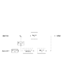
- the flow rate control device 1 includes a valve body 101, a flow rate sensor 102, a conversion unit 103, a control unit 104, and a control valve 105.
- the flow rate control device 1 is a device also called a mass flow controller (also referred to as “MFC”).
- the valve body 101 is a substantially tubular member that defines the upstream flow path 101a and the downstream flow path 101b.
- the upstream side of the upstream flow path 101a and the downstream side of the downstream flow path 101b are connected to a pipe or a flow path block through which the fluid to be controlled flows, respectively.
- the upstream flow path 101a is a flow path that flows in from the fluid from the upstream side. On the way, the upstream flow path 101a branches into a flow path passing through the flow rate sensor 102 and a bypass flow path 101c, then merges and flows out to the control valve 105.
- the control valve 105 has a diaphragm 110 and a valve seat 112 facing the diaphragm 110.
- the space between the diaphragm 110 and the valve seat 112 is a space that communicates between the upstream flow path 101a and the downstream flow path 101b.
- control valve 105 is, for example, a piezo element drive type control valve that opens and closes a metal diaphragm by using a piezo element (piezo actuator) inside the actuator 111. ..
- the downstream flow path 101b is configured such that the fluid whose flow rate is controlled by the control valve 105 flows in from the upstream side and flows out to the downstream side of the flow rate control device 1.
- the bypass flow path 101c is a flow path having a laminar flow element having a structure in which a large number of thin flow paths are arranged in parallel so that the fluid becomes a laminar flow.
- the laminar flow element is configured by stacking a plurality of plates (bypass sheets) having grooves dug by etching.
- the flow rate sensor 102 is a sensor that measures the flow rate of the fluid flowing through the sensor tube 102a.
- the flow rate sensor 102 has heat generating resistors 102b and 102c upstream and downstream of the sensor tube 102a, for example, and measures the flow rate of the fluid flowing through the sensor tube 102a based on the difference in temperature between the heat generating resistors 102b and 102c. Convert to. Since the ratio of the flow rate flowing through the bypass flow path 101c to the flow rate flowing through the sensor tube 102a is known, the flow rate of the upstream flow path 101a can be calculated by measuring the flow rate flowing through the sensor tube 102a.
- the flow rate of the upstream flow rate 101a that is, The range of the flow rate that can be measured by the flow rate control device 1 can be adjusted.
- the conversion unit 103 is a functional unit that converts the flow rate set value into a state that can be compared with the output value of the flow rate sensor 102, and then outputs the output value of the flow rate sensor 102 to the control unit 104.
- the conversion unit 103 may rectify and amplify the output value of the flow rate sensor 102, or apply a low-pass filter to the output value for noise removal.
- the conversion unit 103 outputs the sensor output target value to the control unit 104 after correcting the measurement error caused by the difference according to the type of fluid and the individual difference of the flow rate control device 1 with respect to the flow rate set value. ..
- the control unit 104 is a functional unit that compares the output value of the flow rate sensor 102 with the sensor output target value and controls the control valve 105 based on the comparison result.
- the control unit 104 controls the opening degree of the control valve 105 by performing feedback control so that the flow rate discharged from the downstream flow path 101b becomes the flow rate set value.
- the control unit 104 has a built-in CPU, memory M, A / D converter, and the like.
- the control unit 104 may include a computer program configured to perform an operation described below, and may be realized by a combination of hardware and software.
- Control block of flow control device of related technology has a drive circuit 141, a flow sensor 102, and a sensor response adjustment circuit 143 as control blocks.
- the drive circuit 141 is a circuit that applies a drive current to the control valve 105.
- the drive circuit 141 opens and closes the control valve 105 based on the input flow rate set value, and changes the actual flow rate Q.
- the actual flow rate Q is the flow rate of the fluid physically flowing through the flow rate control device 1.
- the flow rate sensor 102 measures the actual flow rate Q and inputs the voltage value corresponding to the actual flow rate Q into the sensor response adjustment circuit 143.
- the sensor response adjustment circuit 143 is a circuit that corrects the frequency characteristics of the measured values of the flow rate sensor 102.
- the sensor response adjustment circuit 143 is, for example, a band amplification filter having a large gain in a predetermined band and a gain in direct current of 0 dB.
- the drive circuit 141, the flow rate sensor 102, and the sensor response adjustment circuit 143 are connected in this order to form a feedback loop.
- the deviation between the flow rate set value and the output value of the sensor response adjustment circuit 143 is input to the drive circuit 141.
- the drive circuit 141 drives the control valve 105 based on the deviation between the flow rate set value and the output value of the sensor response adjustment circuit 143.
- the output of the sensor response adjustment circuit 143 is input to a display unit (not shown) and displayed as a flow rate display value indicating the current flow rate.
- the guaranteed response speed in the flow control device of the related technology is, for example, about 1 second.
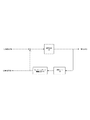
- the flow rate control device 1 has a drive circuit 41, a flow rate sensor 102, a sensor response adjustment circuit 43, and a first filter 44 as control blocks. And has a second filter 45.
- the drive circuit 41, the flow rate sensor 102, the sensor response adjustment circuit 43, and the first filter 44 form a feedback loop in which the flow rate set value is input and the actual flow rate Q is output. The deviation between the flow rate set value and the output value of the first filter 44 is input to the drive circuit 41.
- the drive circuit 41 is a circuit that applies a drive current to the control valve 105.
- the drive circuit 41 opens and closes the control valve 105 based on the input flow rate set value to change the actual flow rate Q.
- the actual flow rate Q is the flow rate of the fluid physically flowing through the flow rate control device 1.
- the flow rate sensor 102 measures the actual flow rate Q and inputs the voltage value corresponding to the actual flow rate Q into the sensor response adjustment circuit 43.
- the sensor response adjustment circuit 43 is a circuit that corrects the frequency characteristics of the measured values of the flow rate sensor 102.
- the thermal flow sensor 102 when the heat transport rate by the fluid such as gas flowing through the flow path is small with respect to the heat capacity of the sensor tube 102a or the heat generating resistor, the heat transport rate by the fluid is lower than the theoretical value. Then, the measured value becomes broad. That is, the measured value of the flow rate sensor 102 is a value obtained by applying a powerful low-pass filter (hereinafter, also referred to as “LPF”) to the actual flow rate Q. Therefore, as shown in FIG.
- LPF powerful low-pass filter
- the sensor response adjustment circuit 43 is a band amplification filter having a gain in the cutoff band of the LPF so as to cancel the attenuation of the LPF caused by the flow sensor 102. Further, the sensor response adjustment circuit 43 may further have the property of a low-pass / high-cut filter that attenuates the high frequency side of the amplified frequency band.
- the first filter 44 shown in FIG. 2 is a frequency filter to which the output of the sensor response adjustment circuit 43 is input. As shown in FIG. 3, the first filter 44 attenuates a predetermined frequency band of the output of the sensor response adjustment circuit 43. The first filter 44 does not change the gain of a frequency different from the frequency band to be attenuated. That is, the gain of a frequency band other than the frequency band is approximately 1. The center frequency of the attenuation band in the first filter 44 is higher than the center frequency of the pass band in the sensor response adjustment circuit 43.
- the first filter 44 Since the first filter 44 attenuates a predetermined frequency band and passes a signal in the low frequency band, the input signal behaves as if it is output with a delay in a situation where the signal is monotonically changing. Therefore, in this feedback loop, the deviation between the signal delayed from the actual flow rate Q and the flow rate set value is taken. When considering the transient response in which the actual flow rate Q gradually approaches the flow rate set value, the delayed signal has a larger deviation from the flow rate set value than the actual flow rate Q, so the first filter 44 is used.
- the drive of the control valve 105 can be increased as compared with the case where the control valve 105 is not used. Therefore, the feedback control can be accelerated and the response speed can be increased.
- the response speed of the flow rate control device 1 is, for example, about 0.5 seconds, and a response speed of about twice that of the flow rate control device of the related technology without the first filter 44 can be realized. According to this configuration, it is possible to respond at high speed even to a transient response when the flow rate set value is significantly changed.
- the second filter 45 is a frequency filter to which the output of the sensor response adjustment circuit 43 is input, and is arranged outside the feedback loop.
- the output of the second filter 45 is input to a display unit (not shown).
- the display unit displays the current flow rate calculated based on the output of the second filter 45 as a flow rate display value.
- the display unit may have a configuration included in the flow rate control device 1, or may be provided in an external device connected to the flow rate control device 1.
- the second filter 45 amplifies a predetermined frequency band in the output of the sensor response adjustment circuit 143, and does not change the gain of a frequency different from the frequency band.
- the center frequencies of the first filter 44 and the second filter 45 are substantially the same.
- the second filter 45 Since the second filter 45 amplifies the frequency in a predetermined band, the change in the signal is emphasized in the time domain, and in the situation where the input value is monotonically changing, the value is corrected with respect to the changing direction. Therefore, it can be expressed that the signal is accelerated by passing through this filter.
- the flow rate display value is a value that more accurately reflects the actual flow rate Q by accelerating the output signal of the sensor response adjustment circuit 43. It can be displayed.
- the sensor response adjustment circuit 43, the first filter 44, and the second filter 45 may be analog filters that process analog signals. According to this configuration, it can be configured at a low cost and can be processed at high speed with low power consumption as compared with the case where it is configured by a digital circuit such as a microcomputer.
- the sensor response adjustment circuit 43 and the second filter 45 are both BPFs that amplify a predetermined band.
- the frequency characteristic obtained by synthesizing the characteristics of the sensor response adjusting circuit 43 and the second filter 45 is realized by one circuit, the frequency characteristic becomes steep and noise may occur. According to the configuration in which the output value of the flow rate sensor 102 is used for calculating the flow rate display value via the sensor response adjustment circuit 43 and the second filter 45, the SN ratio can be guaranteed.
- the first filter 44 and the second filter 45 are filters having opposite frequency characteristics in the sense that the positive and negative gains are different. Further, the sensor response adjustment circuit 43 and the first filter 44 also have frequency characteristics that are substantially opposite to each other, although they have different center frequencies. If filters having opposite frequency characteristics are applied to the same signal, the signal once amplified will be attenuated, which is not desirable in maintaining the SN ratio. According to the configuration in which the output from the sensor response adjustment circuit 43 is branched and the first filter 44 and the second filter 45 are arranged on the respective paths, the use of filters having opposite frequency characteristics is minimized, and the SN The ratio can be guaranteed.
- the sensor response adjustment circuit 43, the first filter 44 and the second filter 45 are separate control blocks
- the sensor response adjustment circuit 43, the first filter 44 and the second filter 45 are composed of analog circuits. Even in this case, the signal can be controlled by the voltage width applied to each analog element.
- the flow rate control device by calculating the flow rate display value based on the output value of the second filter, a value that more accurately reflects the actual flow rate can be displayed as the flow rate display value. ..
- each frequency filter by configuring each frequency filter with an analog filter, it can be configured at a lower cost than when it is configured with a digital circuit such as a microcomputer, and it can be configured at low speed with low power consumption. Can be processed.
- the flow rate control device according to the present invention, high response accuracy can be realized even when the flow rate sensor is a thermal flow rate sensor.
Landscapes
- Physics & Mathematics (AREA)
- General Physics & Mathematics (AREA)
- Fluid Mechanics (AREA)
- Engineering & Computer Science (AREA)
- Automation & Control Theory (AREA)
- Flow Control (AREA)
Abstract
Description
なお、コンピュータプログラムは、インターネット等のネットワークを介したダウンロードによって提供したり、CD-ROMなどのコンピュータが読取可能な各種の記録媒体に記録して提供したりすることができる。
図1に示すように、流量制御装置1は、バルブボディ101、流量センサ102、変換部103、制御部104、および制御弁105を備える。流量制御装置1は、マスフローコントローラ(「MFC」ともいう。)とも呼ばれる装置である。
バイパス流路101cは、流体が層流になる程度に細い流路が多数並列になった構造の層流素子を有する流路である。本実施例では、エッチング加工により溝が掘られた板(バイパスシート)を複数枚積み重ねることによって層流素子が構成されている。
図4に示すように、関連技術の流量制御装置は、制御ブロックとして、駆動回路141、流量センサ102およびセンサレスポンス調整回路143を有する。
図2に示すように、流量制御装置1は、制御ブロックとして、駆動回路41、流量センサ102、センサレスポンス調整回路43、第1フィルタ44および第2フィルタ45を有する。駆動回路41、流量センサ102、センサレスポンス調整回路43および第1フィルタ44は、流量設定値を入力とし、実流量Qを出力とするフィードバックループを構成する。流量設定値と、第1フィルタ44の出力値との偏差が駆動回路41に入力される。
41 駆動回路
43 センサレスポンス調整回路
44 第1フィルタ
45 第2フィルタ
102 流量センサ
104 制御部
105 制御弁
Claims (6)
- 流体の流量を計測する流量センサと、
前記流体の流量が流量設定値になるように流量を調整する制御部と、
を備え、
前記制御部は、
前記流量を変化させる制御弁と、
前記制御弁を駆動する駆動回路と、
前記流量センサの測定値の周波数特性を補正するセンサレスポンス調整回路と、
前記センサレスポンス調整回路の出力の、所定の周波数帯域を減衰させる第1フィルタと、
を備え、
前記駆動回路、前記流量センサ、前記センサレスポンス調整回路および前記第1フィルタを含むフィードバックループが構成され、
前記流量設定値と、前記第1フィルタの出力値と、の偏差が前記駆動回路に入力される、
流量制御装置。
- 前記制御部は、前記フィードバックループの外に、前記センサレスポンス調整回路の出力のうち所定の周波数帯域を増幅させ、前記周波数帯域とは異なる周波数のゲインは変化させない第2フィルタをさらに備える、
請求項1記載の流量制御装置。
- 前記センサレスポンス調整回路と前記第1フィルタは、アナログ信号を処理するアナログフィルタである、
請求項1又は2記載の流量制御装置。
- 前記流量センサは、熱式流量センサである、
請求項1乃至3のいずれかに記載の流量制御装置。
- 流体の流量を計測する流量センサと、
前記流体の流量が流量設定値になるように流量を調整する制御部と、
前記流量を変化させる制御弁と、
を備える流量制御装置を用いる流量制御方法であって、
前記制御弁を駆動する駆動ステップと、
前記流量を計測する計測ステップと、
前記流量センサの測定値の周波数特性を補正するセンサレスポンス調整ステップと、
前記センサレスポンス調整ステップの出力の、所定の周波数帯域を減衰させる減衰ステップと、
を含み、
前記駆動ステップ、前記計測ステップ、前記センサレスポンス調整ステップおよび前記減衰ステップを含むフィードバックループが構成され、
前記流量設定値と、前記減衰ステップの取得値と、の偏差が前記駆動ステップの入力となる、
流量制御方法。
- 流体の流量を計測する流量センサと、
前記流体の流量が流量設定値になるように流量を調整する制御部と、
前記流量を変化させる制御弁と、
を備える流量制御装置の制御プログラムであって、
前記制御弁を駆動する駆動命令と、
前記流量を計測する計測命令と、
前記流量センサの測定値の周波数特性を補正するセンサレスポンス調整命令と、
前記センサレスポンス調整命令の出力の、所定の周波数帯域を減衰させる減衰命令と、
をコンピュータに実行させ、
前記駆動命令、前記計測命令、前記センサレスポンス調整命令および前記減衰命令を含むフィードバックループが構成され、
前記流量設定値と、前記減衰命令の取得値と、の偏差が前記駆動命令の入力となる、
流量制御装置の制御プログラム。
Priority Applications (4)
| Application Number | Priority Date | Filing Date | Title |
|---|---|---|---|
| CN202080018374.XA CN113544620A (zh) | 2019-05-14 | 2020-04-23 | 流量控制装置、流量控制方法、流量控制装置的控制程序 |
| US17/610,759 US20220307882A1 (en) | 2019-05-14 | 2020-04-23 | Flow rate control device, flow rate control method, control program for flow rate control device |
| KR1020217028217A KR102608260B1 (ko) | 2019-05-14 | 2020-04-23 | 유량 제어 장치, 유량 제어 방법, 기록 매체 |
| JP2021519340A JPWO2020230574A1 (ja) | 2019-05-14 | 2020-04-23 |
Applications Claiming Priority (2)
| Application Number | Priority Date | Filing Date | Title |
|---|---|---|---|
| JP2019-091491 | 2019-05-14 | ||
| JP2019091491 | 2019-05-14 |
Publications (1)
| Publication Number | Publication Date |
|---|---|
| WO2020230574A1 true WO2020230574A1 (ja) | 2020-11-19 |
Family
ID=73290189
Family Applications (1)
| Application Number | Title | Priority Date | Filing Date |
|---|---|---|---|
| PCT/JP2020/017480 WO2020230574A1 (ja) | 2019-05-14 | 2020-04-23 | 流量制御装置、流量制御方法、流量制御装置の制御プログラム |
Country Status (6)
| Country | Link |
|---|---|
| US (1) | US20220307882A1 (ja) |
| JP (1) | JPWO2020230574A1 (ja) |
| KR (1) | KR102608260B1 (ja) |
| CN (1) | CN113544620A (ja) |
| TW (1) | TWI755704B (ja) |
| WO (1) | WO2020230574A1 (ja) |
Cited By (1)
| Publication number | Priority date | Publication date | Assignee | Title |
|---|---|---|---|---|
| WO2022239447A1 (ja) * | 2021-05-13 | 2022-11-17 | 株式会社堀場エステック | 流体制御装置、流体制御システム、流体制御装置用プログラム、及び流体制御方法 |
Citations (6)
| Publication number | Priority date | Publication date | Assignee | Title |
|---|---|---|---|---|
| JPH0916268A (ja) * | 1995-06-29 | 1997-01-17 | Hisashi Takahashi | 遅れ補償機能付流量制御弁 |
| JP2003157114A (ja) * | 2001-11-19 | 2003-05-30 | Toshiba Mach Co Ltd | ロストモーション補正方法およびロストモーション補正装置 |
| JP2006500683A (ja) * | 2002-09-26 | 2006-01-05 | スリーエム イノベイティブ プロパティズ カンパニー | 適応型空間ノッチフィルタ |
| JP2009535715A (ja) * | 2006-04-28 | 2009-10-01 | メドトロニック ミニメド インコーポレイテッド | ネットワーク化された液体注入システムのためのモニタデバイスおよびデータ変換デバイス、ならびにモニタ方法およびデータ変換方法 |
| WO2013115298A1 (ja) * | 2012-02-03 | 2013-08-08 | 日立金属株式会社 | 流量制御装置及びプログラム |
| JP2018156557A (ja) * | 2017-03-21 | 2018-10-04 | 株式会社日立産機システム | 遅れ補償器のフィルタの設計方法、及びそれを用いたフィードバック制御方法、モータ制御装置 |
Family Cites Families (7)
| Publication number | Priority date | Publication date | Assignee | Title |
|---|---|---|---|---|
| US7593802B2 (en) * | 2004-10-20 | 2009-09-22 | Fisher Controls International Llc | Lead-lag input filter arrangement for electro-pneumatic control loops |
| US7603186B2 (en) * | 2006-04-28 | 2009-10-13 | Advanced Energy Industries, Inc. | Adaptive response time closed loop control algorithm |
| JP5499381B2 (ja) | 2009-10-20 | 2014-05-21 | 日立金属株式会社 | 流量制御装置 |
| JP5395193B2 (ja) * | 2009-12-01 | 2014-01-22 | 株式会社フジキン | 圧力式流量制御装置 |
| KR101550255B1 (ko) * | 2011-05-10 | 2015-09-04 | 가부시키가이샤 후지킨 | 유량 모니터 부착 압력식 유량 제어 장치와, 이것을 사용한 유체 공급계의 이상 검출 방법 및 모니터 유량 이상 시의 처치 방법 |
| JP5847106B2 (ja) * | 2013-03-25 | 2016-01-20 | 株式会社フジキン | 流量モニタ付圧力式流量制御装置。 |
| CN110431508A (zh) * | 2017-03-28 | 2019-11-08 | 株式会社富士金 | 压力式流量控制裝置以及流量控制方法 |
-
2020
- 2020-04-10 TW TW109112189A patent/TWI755704B/zh active
- 2020-04-23 CN CN202080018374.XA patent/CN113544620A/zh active Pending
- 2020-04-23 WO PCT/JP2020/017480 patent/WO2020230574A1/ja active Application Filing
- 2020-04-23 KR KR1020217028217A patent/KR102608260B1/ko active IP Right Grant
- 2020-04-23 JP JP2021519340A patent/JPWO2020230574A1/ja active Pending
- 2020-04-23 US US17/610,759 patent/US20220307882A1/en active Pending
Patent Citations (6)
| Publication number | Priority date | Publication date | Assignee | Title |
|---|---|---|---|---|
| JPH0916268A (ja) * | 1995-06-29 | 1997-01-17 | Hisashi Takahashi | 遅れ補償機能付流量制御弁 |
| JP2003157114A (ja) * | 2001-11-19 | 2003-05-30 | Toshiba Mach Co Ltd | ロストモーション補正方法およびロストモーション補正装置 |
| JP2006500683A (ja) * | 2002-09-26 | 2006-01-05 | スリーエム イノベイティブ プロパティズ カンパニー | 適応型空間ノッチフィルタ |
| JP2009535715A (ja) * | 2006-04-28 | 2009-10-01 | メドトロニック ミニメド インコーポレイテッド | ネットワーク化された液体注入システムのためのモニタデバイスおよびデータ変換デバイス、ならびにモニタ方法およびデータ変換方法 |
| WO2013115298A1 (ja) * | 2012-02-03 | 2013-08-08 | 日立金属株式会社 | 流量制御装置及びプログラム |
| JP2018156557A (ja) * | 2017-03-21 | 2018-10-04 | 株式会社日立産機システム | 遅れ補償器のフィルタの設計方法、及びそれを用いたフィードバック制御方法、モータ制御装置 |
Cited By (1)
| Publication number | Priority date | Publication date | Assignee | Title |
|---|---|---|---|---|
| WO2022239447A1 (ja) * | 2021-05-13 | 2022-11-17 | 株式会社堀場エステック | 流体制御装置、流体制御システム、流体制御装置用プログラム、及び流体制御方法 |
Also Published As
| Publication number | Publication date |
|---|---|
| TW202045847A (zh) | 2020-12-16 |
| JPWO2020230574A1 (ja) | 2020-11-19 |
| KR20210124364A (ko) | 2021-10-14 |
| TWI755704B (zh) | 2022-02-21 |
| US20220307882A1 (en) | 2022-09-29 |
| KR102608260B1 (ko) | 2023-11-30 |
| CN113544620A (zh) | 2021-10-22 |
Similar Documents
| Publication | Publication Date | Title |
|---|---|---|
| EP1196833B1 (en) | System and method for a variable gain proportional-integral (pi) controller | |
| JP4528617B2 (ja) | マスフローコントローラにおける圧力補償のための方法および装置 | |
| KR101722304B1 (ko) | 매스 플로우 컨트롤러 | |
| CN101454735B (zh) | 自适应响应时间闭环控制算法 | |
| US8195312B2 (en) | Multi-mode control loop with improved performance for mass flow controller | |
| JPH1145122A (ja) | 動的ガス流コントローラ | |
| KR20130086519A (ko) | 일관된 응답을 제공하는 온-툴(on-tool) 및 온-사이트(on-site) 질량 유량계 최적화를 위한 방법 및 시스템 | |
| JPS646481B2 (ja) | ||
| WO2020230574A1 (ja) | 流量制御装置、流量制御方法、流量制御装置の制御プログラム | |
| CN114063658A (zh) | 流量控制装置、流量控制方法和程序存储介质 | |
| JP3893115B2 (ja) | マスフローコントローラ | |
| JP3972495B2 (ja) | ボイラドラムの水位制御装置 | |
| WO2004090652A1 (ja) | 高速気体圧力制御装置 | |
| JP2020107061A (ja) | マスフローコントローラ | |
| JP6799862B2 (ja) | 流量信号補正方法およびこれを用いた流量制御装置 | |
| JP7197943B2 (ja) | 流量制御装置および流量制御方法 | |
| JP2002082722A (ja) | 質量流量制御装置 | |
| JP5170053B2 (ja) | 内燃機関の制御システム | |
| JP2023080611A (ja) | 流量制御装置、流量制御方法、及び、流量制御装置用プログラム | |
| JP2004013249A (ja) | ガス供給システム | |
| JPH0731554B2 (ja) | 流量制御装置 | |
| JP2001141107A (ja) | バルブポジショナ | |
| JP2001306153A (ja) | 質量流量制御装置 | |
| JPH10198435A (ja) | 流体圧力制御装置 | |
| JPH05173579A (ja) | 騒音制御装置 |
Legal Events
| Date | Code | Title | Description |
|---|---|---|---|
| 121 | Ep: the epo has been informed by wipo that ep was designated in this application |
Ref document number: 20806010 Country of ref document: EP Kind code of ref document: A1 |
|
| ENP | Entry into the national phase |
Ref document number: 2021519340 Country of ref document: JP Kind code of ref document: A |
|
| ENP | Entry into the national phase |
Ref document number: 20217028217 Country of ref document: KR Kind code of ref document: A |
|
| NENP | Non-entry into the national phase |
Ref country code: DE |
|
| 122 | Ep: pct application non-entry in european phase |
Ref document number: 20806010 Country of ref document: EP Kind code of ref document: A1 |