WO2020225910A1 - 磁石複合体及び磁石複合体の製造方法 - Google Patents
磁石複合体及び磁石複合体の製造方法 Download PDFInfo
- Publication number
- WO2020225910A1 WO2020225910A1 PCT/JP2019/018586 JP2019018586W WO2020225910A1 WO 2020225910 A1 WO2020225910 A1 WO 2020225910A1 JP 2019018586 W JP2019018586 W JP 2019018586W WO 2020225910 A1 WO2020225910 A1 WO 2020225910A1
- Authority
- WO
- WIPO (PCT)
- Prior art keywords
- magnet
- magnetic material
- metal
- shaft member
- particles
- Prior art date
- Legal status (The legal status is an assumption and is not a legal conclusion. Google has not performed a legal analysis and makes no representation as to the accuracy of the status listed.)
- Ceased
Links
Images
Classifications
-
- B—PERFORMING OPERATIONS; TRANSPORTING
- B22—CASTING; POWDER METALLURGY
- B22F—WORKING METALLIC POWDER; MANUFACTURE OF ARTICLES FROM METALLIC POWDER; MAKING METALLIC POWDER; APPARATUS OR DEVICES SPECIALLY ADAPTED FOR METALLIC POWDER
- B22F3/00—Manufacture of workpieces or articles from metallic powder characterised by the manner of compacting or sintering; Apparatus specially adapted therefor ; Presses and furnaces
-
- B—PERFORMING OPERATIONS; TRANSPORTING
- B22—CASTING; POWDER METALLURGY
- B22F—WORKING METALLIC POWDER; MANUFACTURE OF ARTICLES FROM METALLIC POWDER; MAKING METALLIC POWDER; APPARATUS OR DEVICES SPECIALLY ADAPTED FOR METALLIC POWDER
- B22F1/00—Metallic powder; Treatment of metallic powder, e.g. to facilitate working or to improve properties
-
- C—CHEMISTRY; METALLURGY
- C22—METALLURGY; FERROUS OR NON-FERROUS ALLOYS; TREATMENT OF ALLOYS OR NON-FERROUS METALS
- C22C—ALLOYS
- C22C38/00—Ferrous alloys, e.g. steel alloys
-
- C—CHEMISTRY; METALLURGY
- C22—METALLURGY; FERROUS OR NON-FERROUS ALLOYS; TREATMENT OF ALLOYS OR NON-FERROUS METALS
- C22C—ALLOYS
- C22C9/00—Alloys based on copper
- C22C9/05—Alloys based on copper with manganese as the next major constituent
-
- H—ELECTRICITY
- H01—ELECTRIC ELEMENTS
- H01F—MAGNETS; INDUCTANCES; TRANSFORMERS; SELECTION OF MATERIALS FOR THEIR MAGNETIC PROPERTIES
- H01F1/00—Magnets or magnetic bodies characterised by the magnetic materials therefor; Selection of materials for their magnetic properties
- H01F1/01—Magnets or magnetic bodies characterised by the magnetic materials therefor; Selection of materials for their magnetic properties of inorganic materials
- H01F1/03—Magnets or magnetic bodies characterised by the magnetic materials therefor; Selection of materials for their magnetic properties of inorganic materials characterised by their coercivity
- H01F1/032—Magnets or magnetic bodies characterised by the magnetic materials therefor; Selection of materials for their magnetic properties of inorganic materials characterised by their coercivity of hard-magnetic materials
- H01F1/04—Magnets or magnetic bodies characterised by the magnetic materials therefor; Selection of materials for their magnetic properties of inorganic materials characterised by their coercivity of hard-magnetic materials metals or alloys
- H01F1/047—Alloys characterised by their composition
- H01F1/053—Alloys characterised by their composition containing rare earth metals
- H01F1/055—Alloys characterised by their composition containing rare earth metals and magnetic transition metals, e.g. SmCo5
- H01F1/059—Alloys characterised by their composition containing rare earth metals and magnetic transition metals, e.g. SmCo5 and Va elements, e.g. Sm2Fe17N2
-
- H—ELECTRICITY
- H01—ELECTRIC ELEMENTS
- H01F—MAGNETS; INDUCTANCES; TRANSFORMERS; SELECTION OF MATERIALS FOR THEIR MAGNETIC PROPERTIES
- H01F7/00—Magnets
- H01F7/02—Permanent magnets [PM]
-
- H—ELECTRICITY
- H02—GENERATION; CONVERSION OR DISTRIBUTION OF ELECTRIC POWER
- H02K—DYNAMO-ELECTRIC MACHINES
- H02K15/00—Processes or apparatus specially adapted for manufacturing, assembling, maintaining or repairing of dynamo-electric machines
- H02K15/02—Processes or apparatus specially adapted for manufacturing, assembling, maintaining or repairing of dynamo-electric machines of stator or rotor bodies
- H02K15/03—Processes or apparatus specially adapted for manufacturing, assembling, maintaining or repairing of dynamo-electric machines of stator or rotor bodies having permanent magnets
Definitions
- the present invention relates to a magnet composite and a method for manufacturing a magnet composite.
- Rotors with an annular magnet fixed around the shaft member are used in various electric motors.
- an annular magnet is generally fixed around a shaft member by using an adhesive (see, for example, Patent Document 1).
- the means for solving the above problems include the following aspects.
- a magnet composite comprising a shaft member and a magnet arranged around the shaft member and containing a magnetic material containing a rare earth element and a metal.
- the metal contains at least one of Cu and Al.
- ⁇ 5> The magnet composite according to any one of ⁇ 1> to ⁇ 4>, wherein the magnetic material contains Sm.
- ⁇ 7> The method for producing a magnet composite according to ⁇ 6>, wherein the molded body is formed so that the surface of the shaft member and the surface of the molded body are in contact with each other.
- ⁇ 8> The method for producing a magnet composite according to ⁇ 6> or ⁇ 7>, wherein the metal particles contain a metal having a Vickers hardness Hv of 200 or less.
- ⁇ 9> The method for producing a magnet composite according to any one of ⁇ 6> to ⁇ 8>, wherein the metal contains at least one of Cu and Al.
- ⁇ 10> The method for producing a magnet composite according to any one of ⁇ 6> to ⁇ 9>, wherein the magnetic material particles contain Sm.
- a magnet composite having excellent bonding strength between a member and a magnet and a method for manufacturing the same are provided.
- the present invention is not limited to the following embodiments.
- the components including element steps and the like are not essential unless otherwise specified.
- the term "process” is used in addition to a process independent of other processes, even if the process cannot be clearly distinguished from other processes, as long as the purpose of the process is achieved. Is also included.
- the numerical range indicated by using "-" includes the numerical values before and after "-" as the minimum value and the maximum value, respectively.
- each component may contain a plurality of applicable substances.
- the content rate or content of each component is the total content rate or content of the plurality of substances present in the composition unless otherwise specified.
- the particles corresponding to each component may contain a plurality of types of particles.
- the particle size of each component means a value for a mixture of the plurality of particles present in the composition unless otherwise specified.
- the magnet composite of the present disclosure is a magnet composite including a shaft member and a magnet arranged around the shaft member and containing a magnetic material containing a rare earth element and a metal.
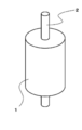
- FIG. 1 schematically shows an example of the structure of the magnet composite of the present disclosure.
- the magnet composite shown in FIG. 1 includes a shaft member 2 and a magnet 1 arranged around the shaft member 2.
- the magnet composite shown in FIG. 1 includes a columnar shaft member 2 and an annular magnet 1 arranged around the columnar shaft member 2, but the present disclosure is not limited thereto.
- the size of each member is conceptual, and the relative relationship between the sizes of the members is not limited to this.
- the magnet composite of the present disclosure has excellent bonding strength between the shaft member and the magnets arranged around the shaft member. The reason is not always clear, but it is conceivable that the magnetic material containing rare earth elements and the molded product containing metal show a phenomenon of shrinkage due to heat treatment. It is considered that this phenomenon improves the adhesion of the molded body (magnet) after the heat treatment to the shaft member and improves the joint strength.
- the magnet can be fixed to the shaft member without using an adhesive or the like. Therefore, as compared with the conventional magnet composite using an adhesive, the bonding strength is excellent and the heat resistance is also excellent.
- the magnets constituting the magnet composite include magnetic materials and metals containing rare earth elements.
- the type of magnetic material is not particularly limited as long as it is a magnetic material containing a rare earth element.
- a magnetic material containing Sm (samarium) as a rare earth element and a magnetic material containing Nd (neodymium) as a rare earth element can be mentioned.
- the magnetic material contained in the magnet may be only one type or a combination of two or more types.
- Examples of the magnetic material containing Sm include Sm-Fe-N magnetic material (Sm 2 Fe 17 N 3 , Sm Fe 7 N x, etc.) and Sm-Fe-B magnetic material (Sm 2 Fe 14 B, Sm 15 Fe 77 B 5). Etc.), Sm-Co magnetic material (SmCo 5 , Sm 2 Co 17, etc.), Sm-Co-N magnetic material (Sm 2 Co 17 N x, etc.), Sm-Co-B magnetic material (Sm 15 Co 77 B 5) Etc.) and so on.
- X represents a positive number.
- Examples of the magnetic material containing Nd include Nd-Fe-B magnetic materials (Nd 2 Fe 14 B and the like).
- the Sm-Fe-N magnetic material is preferable from the viewpoint of excellent balance between coercive force and magnetic flux density.
- the Sm-Fe-N magnetic material means a magnetic material containing Sm, Fe (iron) and N (nitrogen).
- the Sm-Fe-N magnetic material may contain other elements in addition to Sm, Fe and N.
- Other elements include Ga, Nd, Zr, Ti, Cr, Co, Zn, Mn, V, Mo, W, Si, Re, Cu, Al, Ca, B, Ni, C, La, Ce, Pr, Examples thereof include Pm, Eu, Gd, Tb, Dy, Ho, Er, Tm, Yb, Lu, Y, Th and the like. These other elements may be used alone or in combination of two or more.
- Other elements may be introduced by being replaced with a part of the phase structure of the magnet phase containing Sm, Fe and N in an amount of 50% by mass or more, or may be inserted and introduced.
- the total amount of Sm, Fe and N is preferably 50% by mass or more of the total amount.
- the content of the magnetic material contained in the magnet is not particularly limited. From the viewpoint of the balance between magnetic properties and strength, the content of the magnetic material is preferably 20% by mass or more to 99% by mass of the entire magnet. From the viewpoint of improving the strength of the magnet, the content of the magnetic material is more preferably 90% by mass or less, more preferably 85% by mass or less, and particularly preferably 80% by mass or less of the entire magnet. preferable. From the viewpoint of ensuring the magnetic properties of the magnet, the content of the magnetic material is more preferably 30% by mass or more, further preferably 40% by mass or more, and 50% by mass or more of the entire magnet. Is particularly preferable.
- the type of metal contained in the magnet is not particularly limited.
- the term "metal" means a metal or alloy that does not contain rare earth elements.
- the metal preferably has a Vickers hardness Hv of 200 or less.
- the Vickers hardness Hv of the metal is 200 or less, the function as a binder that penetrates between the particles of the magnetic material and bonds the particles to each other is sufficiently exhibited, and the strength of the magnet tends to be improved.
- the upper limit of the Vickers hardness Hv is preferably 150 or less, and more preferably 100 or less.
- the lower limit of the Vickers hardness Hv of the metal is not particularly limited.
- the lower limit of the Vickers hardness Hv of the metal may be, for example, 10 or more, or 30 or more.
- a metal a simple substance of a metal selected from Cu (copper), Al (aluminum), Fe (iron), Ti (titanium), Sn (tin), and In (indium), and an alloy of these metals. Can be mentioned. Among these, at least one of Cu and Al is preferable.
- the metal contained in the magnet may be one kind alone or two or more kinds.
- the metal is selected from the group consisting of copper and P (phosphorus), Co (cobalt), Mn (manganese), Ni (nickel), Zn (zinc), Sn (tin) and Fe (iron). It may be an alloy (copper alloy) containing at least one of them.
- the metal more preferably contains Cu for the reasons shown below.
- a magnet of the desired size is manufactured using a metal having a large specific gravity without changing the metal content (mass standard)
- the ratio (volume ratio) of the magnetic material to the entire magnet is increased. it can. Therefore, it is easy to secure the magnetic characteristics of the magnet without changing the content rate on the basis of mass.
- Cu Since Cu has high ductility, the magnetic material particles and the metal particles in the molded body obtained by molding a mixture of the magnetic material and the metal are easily packed closely, and the density of the molded body is improved. Further, since Cu has excellent slidability (low frictional resistance), it also leads to a long life of the mold used for molding.
- the coefficient of thermal expansion of a magnet containing Cu as a metal is close to the coefficient of thermal expansion of iron (Fe). Therefore, good joint strength is ensured when the shaft member is made of iron.
- the method for measuring the Vickers hardness Hv of metal is as follows. According to JIS Z 2244 (2009), using a Micro Vickers hardness tester (manufactured by Mitutoyo Co., Ltd .: HM-200B), the test piece is pressed against the surface of the test piece with a predetermined test force and formed at that time. The hardness of the test piece is calculated from the diagonal length of the recess.
- the magnet to be measured is subjected to elemental analysis by energy dispersive X-ray analysis (EDS) using a scanning electron microscope (JSM-IT100 manufactured by JEOL Ltd.). Can be done by doing.
- the Vickers hardness Hv can be estimated from the specified metal species.
- the content of metal contained in the magnet is not particularly limited. From the viewpoint of the balance between magnetic properties and strength, the metal content is preferably 1% by mass to 80% by mass of the entire magnet. From the viewpoint of improving the strength of the magnet, the metal content is more preferably 10% by mass or more, further preferably 15% by mass or more, and particularly preferably 20% by mass or more of the entire magnet. .. From the viewpoint of ensuring the magnetic properties of the magnet, the metal content is more preferably 70% by mass or less, more preferably 60% by mass or less, and more preferably 50% by mass or less of the entire magnet. Especially preferable.
- the magnet may contain resin.
- the resin include thermosetting resins such as epoxy resin and phenol resin. From the viewpoint of heat resistance and oil resistance of the magnet, it is preferable that the magnet does not contain a resin or the content of the resin is 10% by mass or less of the whole magnet.
- the magnet may contain at least one of an oxide and a hydroxide of a component contained in the magnetic material (for example, Fe contained in the Sm-Fe-N-based magnetic material particles).
- a component contained in the magnetic material for example, Fe contained in the Sm-Fe-N-based magnetic material particles.
- the state in which the magnet contains at least one of an oxide and a hydroxide as a component contained in the magnetic material is, for example, for a magnet containing magnetic material particles and metal particles, as shown in a method for producing a magnet composite described later.
- the composition can be obtained by heat treatment in an atmosphere containing oxygen.
- the shape of the magnet is not particularly limited as long as it is arranged around the shaft member.
- it may be an annular shape having a through hole at a position corresponding to the shaft member.
- the magnet may be in a state where its surface is in contact with the surface of the shaft member (that is, no adhesive or the like is used).
- the material of the shaft member is not particularly limited.
- it may be a metal generally used for producing a magnet composite.
- it may be iron or an iron-containing alloy (steel, etc.).
- the shape of the shaft member is not particularly limited.
- the cross-sectional shape may be a circle, a polygon, or the like.
- the surface of the shaft member may have irregularities. If the surface of the shaft member is uneven, the effect that the magnet around the shaft member is hard to come off can be expected.
- the method for producing a magnet composite of the present disclosure includes a step of preparing a composition for a magnet containing magnetic material particles containing a rare earth element and a metal particle, and a step of forming a molded body of the composition for a magnet around a shaft member.
- the step of preparing the composition for magnets containing the magnetic material particles and the metal particles is referred to as a composition preparation step for magnets.
- the step of molding the composition for magnets into a molded body is referred to as a molding step.
- the step of heat-treating the molded product in the presence of oxygen is referred to as a heat treatment step.
- heat treatment the treatment performed so that the maximum temperature of the molded product of the magnet composition is 80 ° C. or higher is referred to as "heat treatment".
- the magnet composite produced by the above method has excellent bonding strength between the shaft member and the magnets arranged around the shaft member. The reason is not always clear, but it is conceivable that the magnetic material particles containing rare earth elements and the magnet composition containing metal particles show a phenomenon of shrinkage due to heat treatment. As a result, it is conceivable that the degree of adhesion of the magnet to the shaft member is improved.
- a molded body of a magnet composition is formed around a shaft member and heat-treated to produce a magnet composite. Therefore, it is possible to produce a magnet composite having excellent bonding strength and heat resistance as compared with the conventional method using an adhesive. Further, the manufacturing process can be simplified as compared with the method of fixing the annular magnet manufactured in advance around the shaft member.
- the magnet composite produced by the above method is excellent in magnet strength.
- the reason for this is not necessarily clear, but it is considered that the heat treatment is performed on the molded product of the magnet composition in the presence of oxygen.
- components contained in the magnetic material for example, Fe contained in the Sm-Fe-N-based magnetic material
- the amount of oxide and hydroxide produced tends to increase relatively. This tendency is not seen in heat treatment under an inert gas atmosphere. It is presumed that the relatively increased oxides and hydroxides contribute to the improvement of the strength of the magnet. Furthermore, it is presumed that it also contributes to the improvement of the bonding strength at the interface between the magnet and the shaft member after the heat treatment.
- the heat treatment is performed at a temperature at which the magnetic material contained in the molded product does not sinter. From the viewpoint of ensuring sufficient magnetic properties, it is preferable to perform the heat treatment at a temperature of 500 ° C. or lower. As a result, decomposition of the magnetic material (for example, Sm-Fe-N-based magnetic material) is suppressed, and good magnetic properties tend to be maintained.
- the magnetic material for example, Sm-Fe-N-based magnetic material
- composition Preparation Step for Magnet The method of the composition preparation step for magnets is not particularly limited as long as a composition for magnets containing magnetic material particles and metal particles can be prepared.
- a composition for a magnet may be prepared by mixing magnetic material particles and metal particles.
- the preparation of the composition for a magnet is, for example, a mixing shaker, a tumbler mixer, a V-type mixer, a double cone type mixer, and a ribbon type mixing. It may be performed using a known mixing device such as a machine, a Nauter mixer, a Henschel mixer, or a super mixer.
- the details and preferred embodiments of the magnetic material particles and metal particles contained in the magnet composition are the same as the details and preferred embodiments of the magnetic material and metal contained in the magnet of the magnet composite described above.
- the content of magnetic material particles contained in the magnet composition is not particularly limited. From the viewpoint of the balance between the magnetic properties and the strength, the content of the magnetic material particles is preferably 20% by mass or more to 99% by mass of the entire composition for magnets. From the viewpoint of improving the strength of the magnet, the content of the magnetic material particles is more preferably 90% by mass or less, more preferably 85% by mass or less, and 80% by mass or less of the entire composition for magnets. It is particularly preferable to have. From the viewpoint of ensuring the magnetic properties of the magnet, the content of the magnetic material particles is more preferably 30% by mass or more, still more preferably 40% by mass or more, and 50% by mass of the entire composition for magnets. The above is particularly preferable.
- the content of metal particles contained in the composition for magnets is not particularly limited. From the viewpoint of the balance between the magnetic properties and the strength, the content of the metal particles is preferably 1% by mass to 80% by mass of the entire composition for magnets. From the viewpoint of improving the strength of the magnet, the content of the metal particles is more preferably 10% by mass or more, further preferably 15% by mass or more, and more preferably 20% by mass or more of the entire composition for magnets. Is particularly preferred. From the viewpoint of ensuring the magnetic properties of the magnet, the content of the metal particles is more preferably 70% by mass or less, more preferably 60% by mass or less, and 50% by mass or less of the entire composition for magnets. Is particularly preferable.
- the composition for magnets may contain a resin.
- the resin include thermosetting resins such as epoxy resin and phenol resin. From the viewpoint of heat resistance and oil resistance of the magnet, it is preferable that the composition for magnets does not contain a resin or the content of the resin is 10% by mass or less of the entire composition for magnets.
- the volume average particle diameter (D50) of the magnetic material particles is not particularly limited. For example, it may be selected from the range of 0.1 ⁇ m to 100 ⁇ m. The smaller the volume average particle diameter of the magnetic material particles, the higher the strength of the obtained magnet tends to be. It is considered that this is because the smaller the volume average particle diameter of the magnetic material particles, the larger the surface area of the particles per volume, and the more the formation of oxides and hydroxides on the surface of the magnetic material particles progresses. From the viewpoint of the strength of the magnet, the volume average particle diameter (D50) of the magnetic material particles is preferably 50 ⁇ m or less, more preferably 25 ⁇ m or less, and further preferably 15 ⁇ m or less.
- the volume average particle size (D50) of the magnetic material particles is defined as the particle size (D50) when the accumulation from the small diameter side is 50% in the volume-based particle size distribution measured by the laser diffraction / scattering type particle size distribution measuring device. Can be measured.
- the shape of the magnetic material particles is not particularly limited. From the viewpoint of the magnetic properties of the magnet, the shape of the magnetic material particles is preferably spherical or close to spherical. In the present disclosure, examples of particles having a “spherical or near-spherical shape” include particles having a circularity coefficient of 78% or more or a needle-likeness coefficient of 75% or more. From the viewpoint of the strength of rare earth non-sintered magnets, magnetic material particles having a spherical or near-spherical shape and other shapes (a shape having a circularity coefficient of less than 78% and an needle-likeness coefficient of less than 75%) It may be used in combination with magnetic material particles.
- the magnetic material particles may have a circularity coefficient of 78% or more, 80% or more, 85% or more, or 90% or more. It can be said that the larger the circularity coefficient of the magnetic material particles, the closer the shape of the magnetic material particles is to a spherical shape.
- the magnetic material particles may have an acicularity coefficient of 75% or more, 80% or more, 85% or more, or 90% or more. It can be said that the larger the needle-likeness coefficient of the magnetic material particles, the closer the shape of the magnetic material particles is to a spherical shape.
- the area, peripheral length, major axis and minor axis of the particle image of the magnetic material particles can be measured by observation with a scanning electron microscope (SEM), a transmission electron microscope (TEM), or the like.
- SEM scanning electron microscope
- TEM transmission electron microscope
- the major axis of the magnetic material particles has the longest distance from an arbitrary point a on the surface of the magnetic material particles to an arbitrary point b different from the point a when observing a photographed image of the magnetic material particles.
- the minor axis of the magnetic material particles is perpendicular to the major axis, and is the length of the line segment having the longest length among the line segments connecting the two points on the surface of the magnetic material particles.
- the area, peripheral length, major axis and minor axis of the particle image of the magnetic material particles may be calculated using image software or the like.
- the area, circumference length, major axis, and minor axis of the particle image of the magnetic material particles are obtained as arithmetic mean values of the measured values of 100 particles.
- the volume average particle diameter (D50) of the metal particles is not particularly limited, and is preferably 1 ⁇ m to 100 ⁇ m, more preferably 10 ⁇ m to 80 ⁇ m, and even more preferably 20 ⁇ m to 70 ⁇ m.
- the volume average particle diameter (D50) of the metal particles can be measured in the same manner as the volume average particle diameter (D50) of the magnetic material particles.
- the shape of the metal particles is not particularly limited, and for example, it may be an irregular shape. Since the shape of the metal particles is irregular, there is a tendency that a magnet having excellent strength can be obtained by reducing the number of voids in the case of forming a molded product described later.
- the ratio of the major axis to the minor axis (major axis / minor axis) of the metal particles having an irregular shape is not particularly limited. From the viewpoint of improving the strength, the lower limit of the major axis / minor axis ratio is preferably 1 or more, more preferably 1.5 or more, and further preferably 2 or more.
- the upper limit of the major axis / minor axis ratio is preferably 3.5 or less, and more preferably 3 or less.
- the shape, major axis, minor axis, and major axis / minor axis ratio of the metal particles can be measured by the same method as the measurement of the shape, major axis, minor axis, and major axis / minor axis ratio of the magnetic material particles described above.
- the volume average particle diameter (D50) of the metal particles can be measured in the same manner as the volume average particle diameter (D50) of the magnetic material particles.
- the specific surface area of the metal particles is preferably 0.2 m 2 / g or more from the viewpoint that a sufficient contact area with the magnetic material particles can be obtained and the bonding of the magnetic material particles becomes stronger.
- the upper limit of the specific surface area of the metal particles is not particularly limited, and may be, for example, 2.0 m 2 / g or less.
- the specific surface area of the metal particles can be measured by the BET method (nitrogen gas adsorption method).
- the molding step is not particularly limited as long as a molded body having a desired shape can be formed around the shaft member.
- the compression molding method is preferable.
- the pressure in the case of compression molding is not particularly limited, and the higher the pressure, the higher the magnetic flux density and the higher the strength of the magnet tend to be.
- the pressure in the case of compression molding is low. Therefore, the pressure for compression molding may be, for example, 500 MPa to 2500 MPa.
- the pressure for compression molding is more preferably 700 MPa to 1500 MPa.
- the molded body is formed so that the surface of the shaft member and the surface of the molded body are in contact with each other.
- the density of the molded product obtained in the molding step is not particularly limited, and is preferably 75% to 90%, preferably 80%, based on the true density of the raw material magnet composition. More preferably, it is ⁇ 90%.
- density of the molded product is in the range of 75% to 90% with respect to the true density of the composition for magnets, a magnet having good magnetic characteristics and excellent strength tends to be obtained.
- the mold When a mold is used in the molding process, the mold may be heated and molded, or the mold may be molded without being heated.
- the heating temperature of the mold is not particularly limited.
- the heating temperature of the mold is preferably 100 ° C. to 300 ° C., more preferably 150 ° C. to 250 ° C.
- the heating of the mold is different from the "heat treatment" performed on the molded product obtained in the molding step.
- the molded product obtained in the molding step is heat-treated in the presence of oxygen (that is, heat-treated in an atmosphere containing oxygen).
- the heat treatment method is not particularly limited. For example, it can be carried out using a known device such as a heating furnace.
- the "atmosphere containing oxygen" in which the heat treatment is performed is not particularly limited as long as it is an atmosphere in which oxygen is present.
- oxygen gas may be supplied or the operation may be performed in the atmosphere. From an economical point of view, it is preferable to carry out the operation in the atmosphere (generally, the oxygen concentration in the components excluding water is about 23% by mass).
- the oxygen concentration in the atmosphere in which oxygen is present is not particularly limited. From the viewpoint of promoting the formation of oxides and hydroxides by heat treatment, the oxygen concentration may be, for example, 10% by mass or more. From the viewpoint of suppressing the excessive formation of oxides and hydroxides, the oxygen concentration may be, for example, 40% by mass or less.
- the heat treatment step is preferably performed in an atmosphere containing water vapor (that is, performed in an atmosphere containing oxygen and water vapor).
- an atmosphere containing oxygen that is, performed in an atmosphere containing oxygen and water vapor.
- the heat treatment is performed in an atmosphere containing oxygen
- the water content in the magnet composition reacts with the components of the magnetic material particles to generate hydroxides and oxides.
- the heat treatment is performed in an atmosphere further containing water vapor in addition to oxygen
- the water content contained in the magnet composition reacts with the water vapor and the components of the magnetic material particles to form hydroxides and oxides. Is considered to be promoted more.
- the strength of the obtained magnet is further improved.
- the joint strength between the shaft member and the magnet is further improved.
- the concentration (humidity) of water vapor in an atmosphere containing water vapor is not particularly limited.
- the humidity of the atmosphere containing water vapor is preferably 10% or more as a relative humidity, for example.
- the concentration of water vapor is, for example, 80% or less as a relative humidity from the viewpoint of suppressing a decrease in the strength of the magnet due to an excessively large amount of hydroxides and oxides produced in the magnet. Is preferable, and 70% or less is more preferable.
- the heat treatment may be performed under reduced pressure, pressurized pressure, or atmospheric pressure. From an economic point of view, it is preferable to carry out under atmospheric pressure.
- the heat treatment temperature is not particularly limited.
- the temperature of the heat treatment is preferably not too high from the viewpoint of avoiding that the magnetic material particles are thermally decomposed or the metal particles are melted and diffused into the magnetic material particles to deteriorate the magnetic properties. Therefore, the temperature of the heat treatment is preferably 500 ° C. or lower, more preferably 400 ° C. or lower, and more preferably 250 ° C. or lower, from the viewpoint of obtaining a rare earth metal bond magnet having excellent strength while ensuring magnetic characteristics. It is more preferable that the temperature is 200 ° C. or lower. Further, from the viewpoint of further enhancing the effect of the heat treatment, the lower limit of the heat treatment temperature is preferably 100 ° C. or higher, more preferably 150 ° C. or higher, and further preferably 180 ° C. or higher.
- the heat treatment temperature in the present disclosure represents the maximum temperature reached.
- the heat treatment time (holding time at the maximum temperature reached) is not particularly limited. From the viewpoint of obtaining a sufficient heat treatment effect, the heat treatment time is preferably 10 minutes or more, more preferably 30 minutes or more, and further preferably 1 hour or more. From the viewpoint of mass productivity, the heat treatment time is preferably 100 hours or less.
- the rate of temperature rise until the maximum temperature is reached is not particularly limited.
- the lower limit of the heating rate may be, for example, 2 ° C./min or more, or 5 ° C./min or more.
- the upper limit of the heating rate may be, for example, 20 ° C./min or less, or 15 ° C./min or less.
- the molded product is cooled until the temperature of the molded product reaches room temperature (for example, 25 ° C.).
- the cooling rate is not particularly limited.
- the lower limit of the cooling rate may be, for example, 2 ° C./min or more, or 5 ° C./min or more.
- the upper limit of the cooling rate may be, for example, 20 ° C./min or less, or 15 ° C./min or less.
- composition for magnet (Preparation of composition for magnet) The composition for magnets of Examples was prepared by mixing the magnetic material particles and metal particles shown in Table 1 in an amount (unit: parts by mass) shown in Table 1. The magnetic material particles and the metal particles were mixed using a stirrer at about 50 rpm for 30 minutes.
- Magnetic material particles Sm-Fe-N magnetic material particles (manufactured by Sumitomo Metal Mining Co., Ltd., volume average particle diameter 2 ⁇ m to 5 ⁇ m, circularity coefficient: 78% or more, needle shape coefficient: 75% or more)
- Metal particles 1 Copper particles (Fukuda Metal Foil Powder Industry Co., Ltd. "CE-15”, electrolytic copper powder, major axis / minor axis ratio: 2.8, Vickers hardness Hv: 50, volume average particle diameter: 50 ⁇ m)
- Metal particles 2 Copper manganese alloy particles (Nippon Atomize Processing Co., Ltd. "SF-CuMn", water atomize powder, major axis / minor axis ratio: 1.5, Vickers hardness Hv: 75, volume average particle diameter: 44 ⁇ m, manganese Content: 35% by mass)
- the obtained molded body was heat-treated under the conditions of atmospheric pressure, oxygen presence (oxygen concentration 23% by mass, relative humidity 60%), maximum ultimate temperature 250 ° C., and 80 hours to prepare a magnet composite.
- the magnet composite in which the magnet formed around the shaft member contains a magnetic material and a metal is excellent because the load (extraction load) at the time when the shaft member is removed from the magnet is sufficiently large.
- the joint strength was shown.
- the extraction load of the magnet composite after the heat treatment was larger than that of the molded product before the heat treatment, and the bonding strength tended to be improved.
Landscapes
- Engineering & Computer Science (AREA)
- Chemical & Material Sciences (AREA)
- Mechanical Engineering (AREA)
- Manufacturing & Machinery (AREA)
- Power Engineering (AREA)
- Materials Engineering (AREA)
- Metallurgy (AREA)
- Organic Chemistry (AREA)
- Electromagnetism (AREA)
- Physics & Mathematics (AREA)
- Crystallography & Structural Chemistry (AREA)
- Inorganic Chemistry (AREA)
- Hard Magnetic Materials (AREA)
- Manufacturing Cores, Coils, And Magnets (AREA)
- Permanent Field Magnets Of Synchronous Machinery (AREA)
- Powder Metallurgy (AREA)
Abstract
軸部材と、前記軸部材の周囲に配置され、希土類元素を含む磁性材及び金属を含む磁石と、を備える磁石複合体。
Description
本発明は、磁石複合体及び磁石複合体の製造方法に関する。
軸部材の周囲に環状の磁石を固定した状態の回転子が、各種電動機に利用されている。このような回転子は一般に、環状の磁石が軸部材の周囲に接着剤を用いて固定されている(例えば、特許文献1参照)。
環状の磁石を軸部材の周囲に接着剤を用いて固定して製造される回転子は、接着剤として樹脂を用いているために、軸部材と磁石との接合強度に改善の余地がある。
本発明は上記事情に鑑み、軸部材と磁石との接合強度に優れる磁石複合体及びその製造方法を提供することを課題とする。
本発明は上記事情に鑑み、軸部材と磁石との接合強度に優れる磁石複合体及びその製造方法を提供することを課題とする。
上記課題を解決するための手段には、以下の態様が含まれる。
<1>軸部材と、前記軸部材の周囲に配置され、希土類元素を含む磁性材及び金属を含む磁石と、を備える磁石複合体。
<2>前記軸部材の表面と前記磁石の表面とが接している、<1>に記載の磁石複合体。
<3>前記金属はビッカース硬さHvが200以下である金属を含む、<1>又は<2>に記載の磁石複合体。
<4>前記金属はCu及びAlの少なくともいずれかを含む、<1>~<3>のいずれか1項に記載の磁石複合体。
<5>前記磁性材はSmを含む、<1>~<4>のいずれか1項に記載の磁石複合体。
<6>希土類元素を含む磁性材粒子及び金属粒子を含む磁石用組成物を準備する工程と、前記磁石用組成物の成形体を軸部材の周囲に形成する工程と、前記成形体を酸素存在下で熱処理する工程と、を有する磁石複合体の製造方法。
<7>前記軸部材の表面と前記成形体の表面とが接するように前記成形体が形成される、<6>に記載の磁石複合体の製造方法。
<8>前記金属粒子はビッカース硬さHvが200以下である金属を含む、<6>又は<7>に記載の磁石複合体の製造方法。
<9>前記金属はCu及びAlの少なくともいずれかを含む、<6>~<8>のいずれか1項に記載の磁石複合体の製造方法。
<10>前記磁性材粒子はSmを含む、<6>~<9>のいずれか1項に記載の磁石複合体の製造方法。
<1>軸部材と、前記軸部材の周囲に配置され、希土類元素を含む磁性材及び金属を含む磁石と、を備える磁石複合体。
<2>前記軸部材の表面と前記磁石の表面とが接している、<1>に記載の磁石複合体。
<3>前記金属はビッカース硬さHvが200以下である金属を含む、<1>又は<2>に記載の磁石複合体。
<4>前記金属はCu及びAlの少なくともいずれかを含む、<1>~<3>のいずれか1項に記載の磁石複合体。
<5>前記磁性材はSmを含む、<1>~<4>のいずれか1項に記載の磁石複合体。
<6>希土類元素を含む磁性材粒子及び金属粒子を含む磁石用組成物を準備する工程と、前記磁石用組成物の成形体を軸部材の周囲に形成する工程と、前記成形体を酸素存在下で熱処理する工程と、を有する磁石複合体の製造方法。
<7>前記軸部材の表面と前記成形体の表面とが接するように前記成形体が形成される、<6>に記載の磁石複合体の製造方法。
<8>前記金属粒子はビッカース硬さHvが200以下である金属を含む、<6>又は<7>に記載の磁石複合体の製造方法。
<9>前記金属はCu及びAlの少なくともいずれかを含む、<6>~<8>のいずれか1項に記載の磁石複合体の製造方法。
<10>前記磁性材粒子はSmを含む、<6>~<9>のいずれか1項に記載の磁石複合体の製造方法。
本開示によれば、部材と磁石との接合強度に優れる磁石複合体及びその製造方法が提供される。
以下、本発明の一実施形態について詳細に説明する。但し、本発明は以下の実施形態に限定されるものではない。以下の実施形態において、その構成要素(要素ステップ等も含む)は、特に明示した場合を除き、必須ではない。数値及びその範囲についても同様であり、本発明を制限するものではない。
本開示において「工程」との語には、他の工程から独立した工程に加え、他の工程と明確に区別できない場合であっても、その工程の目的が達成されるのであれば、当該工程も含まれる。
本開示において「~」を用いて示された数値範囲には、「~」の前後に記載される数値がそれぞれ最小値及び最大値として含まれる。
本開示中に段階的に記載されている数値範囲において、一つの数値範囲で記載された上限値又は下限値は、他の段階的な記載の数値範囲の上限値又は下限値に置き換えてもよい。また、本開示中に記載されている数値範囲において、その数値範囲の上限値又は下限値は、実施例に示されている値に置き換えてもよい。
本開示において各成分は、該当する物質を複数種含んでいてもよい。組成物中に各成分に該当する物質が複数種存在する場合、各成分の含有率又は含有量は、特に断らない限り、組成物中に存在する当該複数種の物質の合計の含有率又は含有量を意味する。
本開示において各成分に該当する粒子は複数種の粒子を含んでいてもよい。組成物中に各成分に該当する粒子が複数種存在する場合、各成分の粒子径は、特に断らない限り、組成物中に存在する当該複数種の粒子の混合物についての値を意味する。
本開示において「工程」との語には、他の工程から独立した工程に加え、他の工程と明確に区別できない場合であっても、その工程の目的が達成されるのであれば、当該工程も含まれる。
本開示において「~」を用いて示された数値範囲には、「~」の前後に記載される数値がそれぞれ最小値及び最大値として含まれる。
本開示中に段階的に記載されている数値範囲において、一つの数値範囲で記載された上限値又は下限値は、他の段階的な記載の数値範囲の上限値又は下限値に置き換えてもよい。また、本開示中に記載されている数値範囲において、その数値範囲の上限値又は下限値は、実施例に示されている値に置き換えてもよい。
本開示において各成分は、該当する物質を複数種含んでいてもよい。組成物中に各成分に該当する物質が複数種存在する場合、各成分の含有率又は含有量は、特に断らない限り、組成物中に存在する当該複数種の物質の合計の含有率又は含有量を意味する。
本開示において各成分に該当する粒子は複数種の粒子を含んでいてもよい。組成物中に各成分に該当する粒子が複数種存在する場合、各成分の粒子径は、特に断らない限り、組成物中に存在する当該複数種の粒子の混合物についての値を意味する。
<磁石複合体>
本開示の磁石複合体は、軸部材と、前記軸部材の周囲に配置され、希土類元素を含む磁性材及び金属を含む磁石と、を備える磁石複合体である。
本開示の磁石複合体は、軸部材と、前記軸部材の周囲に配置され、希土類元素を含む磁性材及び金属を含む磁石と、を備える磁石複合体である。
図1に、本開示の磁石複合体の構造の一例を概略的に示す。図1に示す磁石複合体は、軸部材2と、軸部材2の周囲に配置される磁石1とを備えている。図1に示す磁石複合体は円柱状の軸部材2と、その周囲に配置される環状の磁石1とを備えているが、本開示はこれに限定されるものではない。また各部材の大きさは概念的なものであり、部材間の大きさの相対的な関係はこれに限定されない。
本開示の磁石複合体は、軸部材と、その周囲に配置される磁石との接合強度に優れている。その理由は必ずしも明らかではないが、希土類元素を含む磁性材及び金属を含む成形体は熱処理により収縮する現象を示すことが考えられる。この現象により熱処理後の成形体(磁石)の軸部材に対する密着性が向上して、接合強度が向上することが考えられる。
本開示の磁石複合体は、接着剤等を用いずに磁石を軸部材に固定することができる。このため、接着剤を用いる従来の磁石複合体に比べて接合強度に優れるとともに耐熱性にも優れている。
(磁石)
磁石複合体を構成する磁石は、希土類元素を含む磁性材及び金属を含む。
磁性材は、希土類元素を含む磁性材であれば、その種類は特に限定されない。例えば、希土類元素としてSm(サマリウム)を含む磁性材、及び希土類元素としてNd(ネオジム)を含む磁性材が挙げられる。磁石に含まれる磁性材は、1種のみであっても、2種以上の組み合わせであってもよい。
磁石複合体を構成する磁石は、希土類元素を含む磁性材及び金属を含む。
磁性材は、希土類元素を含む磁性材であれば、その種類は特に限定されない。例えば、希土類元素としてSm(サマリウム)を含む磁性材、及び希土類元素としてNd(ネオジム)を含む磁性材が挙げられる。磁石に含まれる磁性材は、1種のみであっても、2種以上の組み合わせであってもよい。
Smを含む磁性材としては、Sm-Fe-N磁性材(Sm2Fe17N3、SmFe7Nx等)、Sm-Fe-B磁性材(Sm2Fe14B、Sm15Fe77B5等)、Sm-Co磁性材(SmCo5、Sm2Co17等)、Sm-Co-N磁性材(Sm2Co17Nx等)、Sm-Co-B磁性材(Sm15Co77B5等)などが挙げられる。以上の式においてXは正の数を示す。
Ndを含む磁性材としては、Nd-Fe-B磁性材(Nd2Fe14B等)などが挙げられる。
Ndを含む磁性材としては、Nd-Fe-B磁性材(Nd2Fe14B等)などが挙げられる。
Smを含む磁性材の中でも、保磁力及び磁束密度のバランスに優れる観点で、Sm-Fe-N磁性材が好ましい。
ここで、Sm-Fe―N磁性材とは、Sm、Fe(鉄)及びN(窒素)を含む磁性材を意味する。
ここで、Sm-Fe―N磁性材とは、Sm、Fe(鉄)及びN(窒素)を含む磁性材を意味する。
Sm-Fe-N磁性材は、Sm、Fe及びN以外に、他の元素を含有していてもよい。他の元素としては、Ga、Nd、Zr、Ti、Cr、Co、Zn、Mn、V、Mo、W、Si、Re、Cu、Al、Ca、B、Ni、C、La、Ce、Pr、Pm、Eu、Gd、Tb、Dy、Ho、Er、Tm、Yb、Lu、Y、Th等が挙げられる。これら他の元素は、1種単独で用いてもよく、2種以上を併用してもよい。他の元素は、Sm、Fe及びNを50質量%以上で含有する磁石相の相構造の一部と置換されていて導入されていてもよく、挿入されて導入されていてもよい。Sm-Fe-N磁性材が、Sm、Fe及びN以外の元素を含有する場合、Sm、Fe及びNの総量が全体の50質量%以上であることが好ましい。
磁石に含まれる磁性材の含有率は、特に限定されない。磁気特性と強度のバランスの観点からは、磁性材の含有率は、磁石全体の20質量%以上~99質量%であることが好ましい。磁石の強度向上の観点からは、磁性材の含有率は、磁石全体の90質量%以下であることがより好ましく、85質量%以下であることがさらに好ましく、80質量%以下であることが特に好ましい。磁石の磁気特性を確保する観点からは、磁性材の含有率は、磁石全体の30質量%以上であることがより好ましく、40質量%以上であることがさらに好ましく、50質量%以上であることが特に好ましい。
磁石に含まれる金属の種類は、特に制限されない。本開示において「金属」とは、希土類元素を含まない金属又は合金を意味する。
金属は、ビッカース硬さHvが200以下であることが好ましい。金属のビッカース硬さHvが200以下であると、磁性材の粒子の間に入り込んで粒子同士を結合するバインダとしての機能が充分に発揮されて、磁石の強度が向上する傾向にある。金属のバインダとしての機能の観点からは、ビッカース硬さHvの上限値は、150以下であることが好ましく、100以下であることがより好ましい。
金属のビッカース硬さHvの下限値は、特に限定されるものではない。金属のビッカース硬さHvの下限値は、例えば、10以上であってもよく、30以上であってもよい。
金属は、ビッカース硬さHvが200以下であることが好ましい。金属のビッカース硬さHvが200以下であると、磁性材の粒子の間に入り込んで粒子同士を結合するバインダとしての機能が充分に発揮されて、磁石の強度が向上する傾向にある。金属のバインダとしての機能の観点からは、ビッカース硬さHvの上限値は、150以下であることが好ましく、100以下であることがより好ましい。
金属のビッカース硬さHvの下限値は、特に限定されるものではない。金属のビッカース硬さHvの下限値は、例えば、10以上であってもよく、30以上であってもよい。
金属として具体的には、Cu(銅)、Al(アルミニウム)、Fe(鉄)、Ti(チタン)、Sn(錫)、及びIn(インジウム)から選択される金属の単体、並びにこれら金属の合金が挙げられる。これらの中でも、Cu及びAlの少なくともいずれかが好ましい。磁石に含まれる金属は、1種単独でも2種以上であってもよい。
ある実施態様では、金属は銅と、P(リン)、Co(コバルト)、Mn(マンガン)、Ni(ニッケル)、Zn(亜鉛)、Sn(錫)及びFe(鉄)からなる群より選択される少なくとも1種と、を含む合金(銅合金)であってもよい。
金属は、下記に示す理由から、Cuを含むことがより好ましい。
(1)金属の含有率(質量基準)を変更せずに比重の大きい金属を用いて、目的とする大きさの磁石を作製する場合に、磁石全体に対する磁性材の割合(体積比)を大きくできる。そのため、質量基準での含有率を変更せずに磁石の磁気特性を確保しやすい。
(2)Cuは延性が高いため、磁性材と金属の混合物を成形して得られる成形体中の磁性材粒子と金属粒子が最密充填されやすくなり、成形体の密度が向上する。さらに、Cuは摺動性に優れる(摩擦抵抗が低い)ため、成形に用いる金型の長寿命化にも繋がる。
(3)金属としてCuを含む磁石の熱膨張率は、鉄(Fe)の熱膨張率に近くなる。そのため、軸部材が鉄製である場合に良好な接合強度が確保される。
(1)金属の含有率(質量基準)を変更せずに比重の大きい金属を用いて、目的とする大きさの磁石を作製する場合に、磁石全体に対する磁性材の割合(体積比)を大きくできる。そのため、質量基準での含有率を変更せずに磁石の磁気特性を確保しやすい。
(2)Cuは延性が高いため、磁性材と金属の混合物を成形して得られる成形体中の磁性材粒子と金属粒子が最密充填されやすくなり、成形体の密度が向上する。さらに、Cuは摺動性に優れる(摩擦抵抗が低い)ため、成形に用いる金型の長寿命化にも繋がる。
(3)金属としてCuを含む磁石の熱膨張率は、鉄(Fe)の熱膨張率に近くなる。そのため、軸部材が鉄製である場合に良好な接合強度が確保される。
金属のビッカース硬さHvの測定方法は、以下のとおりである。JIS Z 2244(2009)に準じて、マイクロビッカース硬さ試験機(株式会社ミツトヨ製:HM-200B)を用いて、予め定められた試験力にて試験体の表面に押圧し、その際に形成されたくぼみの対角線長さから試験体の硬度を算出する。
磁石に含まれる金属種の特定は、例えば、測定対象となる磁石に対し、走査型電子顕微鏡(日本電子株式会社製:JSM-IT100)を用いたエネルギー分散型X線分析(EDS)により元素分析を行って行うことができる。また、特定された金属種から、そのビッカース硬さHvを推定することができる。
磁石に含まれる金属の含有率は、特に限定されない。磁気特性と強度のバランスの観点からは、金属の含有率は、磁石全体の1質量%~80質量%であることが好ましい。磁石の強度向上の観点からは、金属の含有率は、磁石全体の10質量%以上であることがより好ましく、15質量%以上であることがさらに好ましく、20質量%以上であることが特に好ましい。磁石の磁気特性を確保する観点からは、金属の含有率は、磁石全体の70質量%以下であることがより好ましく、60質量%以下であることがさらに好ましく、50質量%以下であることが特に好ましい。
磁石は、樹脂を含んでもよい。樹脂としては、エポキシ樹脂、フェノール樹脂等の熱硬化性樹脂が挙げられる。磁石の耐熱性及び耐油性の観点からは、磁石は樹脂を含まないか、樹脂の含有率が磁石全体の10質量%以下であることが好ましい。
磁石は、磁性材に含まれる成分(例えば、Sm-Fe-N系磁性材粒子に含まれるFe)の酸化物及び水酸化物の少なくともいずれかを含んでもよい。磁石が磁性材に含まれる成分の酸化物及び水酸化物を含んでいると、磁性材の粒子同士の接合強度、及び磁石と軸部材との接合強度がより向上すると考えられる。
磁石が磁性材に含まれる成分の酸化物及び水酸化物の少なくともいずれかを含む状態は、たとえば、後述する磁石複合体の製造方法に示すように、磁性材粒子と金属粒子とを含む磁石用組成物を、酸素を含む雰囲気中で熱処理することで得ることができる。
磁石の形状は、軸部材の周囲に配置される形状であれば特に制限されない。例えば、軸部材に相当する位置に貫通穴を有する環状であってもよい。磁石は、その表面と軸部材の表面とが接した状態(すなわち、接着剤等を用いない)であってもよい。
(軸部材)
軸部材の材質は、特に制限されない。例えば、磁石複合体の製造に一般的に用いられる金属であってもよい。ある実施態様では、鉄又は鉄を含む合金(鋼等)であってもよい。
軸部材の材質は、特に制限されない。例えば、磁石複合体の製造に一般的に用いられる金属であってもよい。ある実施態様では、鉄又は鉄を含む合金(鋼等)であってもよい。
軸部材の形状は、特に制限されない。例えば、断面形状が円、多角形等であってもよい。また、軸部材の表面に凹凸が形成されていてもよい。軸部材の表面に凹凸が形成されていると、軸部材の周囲の磁石が外れにくくなる等の効果が期待できる。
<磁石複合体の製造方法>
本開示の磁石複合体の製造方法は、希土類元素を含む磁性材粒子及び金属粒子を含む磁石用組成物を準備する工程と、前記磁石用組成物の成形体を軸部材の周囲に形成する工程と、前記成形体を酸素存在下で熱処理する工程と、を有する磁石複合体の製造方法である。
本開示の磁石複合体の製造方法は、希土類元素を含む磁性材粒子及び金属粒子を含む磁石用組成物を準備する工程と、前記磁石用組成物の成形体を軸部材の周囲に形成する工程と、前記成形体を酸素存在下で熱処理する工程と、を有する磁石複合体の製造方法である。
以下、磁性材粒子及び金属粒子を含む磁石用組成物を準備する工程を、磁石用組成物準備工程と称する。前記磁石用組成物を成形して成形体とする工程を、成形工程と称する。前記成形体を酸素存在下で熱処理する工程を、熱処理工程と称する。
本開示では、磁石用組成物の成形体の最高到達温度が80℃以上となるように行う処理を「熱処理」と称する。
本開示では、磁石用組成物の成形体の最高到達温度が80℃以上となるように行う処理を「熱処理」と称する。
上記方法により製造される磁石複合体は、軸部材と、その周囲に配置される磁石との接合強度に優れている。その理由は必ずしも明らかではないが、希土類元素を含む磁性材粒子及び金属粒子を含む磁石組成物は、熱処理により収縮する現象を示すことが考えられる。その結果、磁石の軸部材に対する密着度が向上することが考えられる。
上記方法では、磁石用組成物の成形体を軸部材の周囲に形成し、これを熱処理して磁石複合体を製造する。このため、接着剤を用いる従来の方法に比べて接合強度に優れるとともに耐熱性にも優れる磁石複合体を製造することができる。また、あらかじめ作製した環状の磁石を軸部材の周囲に固定する方法に比べて製造工程を簡略化することができる。
さらに上記方法で製造される磁石複合体は、磁石の強度に優れている。この理由は必ずしも明らかではないが、酸素存在下で磁石用組成物の成形体の熱処理を行うためと考えられる。酸素存在下で磁石用組成物の成形体の熱処理を行うことにより、磁性材粒子と金属粒子との境界において、磁性材に含まれる成分(例えば、Sm-Fe-N系磁性材に含まれるFe)の酸化物及び水酸化物の生成量が、相対的に増加する傾向がみられる。この傾向は、不活性ガス雰囲気下における熱処理ではみられないものである。そして、この相対的に増加した酸化物及び水酸化物が、磁石の強度の向上に寄与していると推測される。さらに、熱処理後の磁石と軸部材との界面における接合強度の向上にも寄与していると推測される。
上記方法では、熱処理を成形体に含まれる磁性材が焼結しない温度で行うことが好ましい。充分な磁気特性を確保する観点からは、熱処理を500℃以下の温度で行うことが好ましい。これにより、磁性材(例えば、Sm-Fe-N系磁性材)の分解が抑制され、良好な磁気特性が維持される傾向にある。
(1)磁石用組成物準備工程
磁石用組成物準備工程は、磁性材粒子と金属粒子とを含む磁石用組成物を準備できるものであれば、その方法は特に限定されるものではない。例えば、磁性材粒子と金属粒子とを混合して磁石用組成物を調製してもよい。
磁性材粒子と金属粒子とを混合して磁石用組成物を調製する場合、磁石用組成物の調製は、例えば、ミキシングシェーカー、タンブラーミキサー、V型混合機、ダブルコーン型混合機、リボン型混合機、ナウターミキサー、ヘンシェルミキサー、スーパーミキサー等の公知の混合装置を用いて行ってもよい。
磁石用組成物準備工程は、磁性材粒子と金属粒子とを含む磁石用組成物を準備できるものであれば、その方法は特に限定されるものではない。例えば、磁性材粒子と金属粒子とを混合して磁石用組成物を調製してもよい。
磁性材粒子と金属粒子とを混合して磁石用組成物を調製する場合、磁石用組成物の調製は、例えば、ミキシングシェーカー、タンブラーミキサー、V型混合機、ダブルコーン型混合機、リボン型混合機、ナウターミキサー、ヘンシェルミキサー、スーパーミキサー等の公知の混合装置を用いて行ってもよい。
磁石用組成物に含まれる磁性材粒子及び金属粒子の詳細及び好ましい態様は、上述した磁石複合体の磁石に含まれる磁性材及び金属の詳細及び好ましい態様と同様である。
磁石用組成物に含まれる磁性材粒子の含有率は、特に限定されない。磁気特性と強度のバランスの観点からは、磁性材粒子の含有率は、磁石用組成物全体の20質量%以上~99質量%であることが好ましい。磁石の強度向上の観点からは、磁性材粒子の含有率は、磁石用組成物全体の90質量%以下であることがより好ましく、85質量%以下であることがさらに好ましく、80質量%以下であることが特に好ましい。磁石の磁気特性を確保する観点からは、磁性材粒子の含有率は、磁石用組成物全体の30質量%以上であることがより好ましく、40質量%以上であることがさらに好ましく、50質量%以上であることが特に好ましい。
磁石用組成物に含まれる金属粒子の含有率は、特に限定されない。磁気特性と強度のバランスの観点からは、金属粒子の含有率は、磁石用組成物全体の1質量%~80質量%であることが好ましい。磁石の強度向上の観点からは、金属粒子の含有率は、磁石用組成物全体の10質量%以上であることがより好ましく、15質量%以上であることがさらに好ましく、20質量%以上であることが特に好ましい。磁石の磁気特性を確保する観点からは、金属粒子の含有率は、磁石用組成物全体の70質量%以下であることがより好ましく、60質量%以下であることがさらに好ましく、50質量%以下であることが特に好ましい。
磁石用組成物は、樹脂を含んでもよい。樹脂としては、エポキシ樹脂、フェノール樹脂等の熱硬化性樹脂が挙げられる。磁石の耐熱性及び耐油性の観点からは、磁石用組成物は樹脂を含まないか、樹脂の含有率が磁石用組成物全体の10質量%以下であることが好ましい。
磁性材粒子の体積平均粒子径(D50)は、特に限定されない。例えば、0.1μm~100μmの範囲から選択してもよい。
磁性材粒子の体積平均粒子径が小さいほど、得られる磁石の強度が向上する傾向にある。これは、磁性材粒子の体積平均粒子径が小さいほど体積当たりの粒子の表面積が増大し、磁性材粒子表面における酸化物及び水酸化物の生成が進行するためと考えられる。磁石の強度の観点からは、磁性材粒子の体積平均粒子径(D50)は、50μm以下であることが好ましく、25μm以下であることがより好ましく、15μm以下であることがさらに好ましい。
磁石の強度及び磁気特性のバランスの観点からは、体積平均粒子径(D50)が異なる2種以上の磁性材粒子を併用してもよい。
磁性材粒子の体積平均粒子径(D50)は、レーザー回折散乱式粒度分布測定装置により測定された体積基準の粒度分布において、小径側からの累積が50%となるときの粒子径(D50)として測定することができる。
磁性材粒子の体積平均粒子径が小さいほど、得られる磁石の強度が向上する傾向にある。これは、磁性材粒子の体積平均粒子径が小さいほど体積当たりの粒子の表面積が増大し、磁性材粒子表面における酸化物及び水酸化物の生成が進行するためと考えられる。磁石の強度の観点からは、磁性材粒子の体積平均粒子径(D50)は、50μm以下であることが好ましく、25μm以下であることがより好ましく、15μm以下であることがさらに好ましい。
磁石の強度及び磁気特性のバランスの観点からは、体積平均粒子径(D50)が異なる2種以上の磁性材粒子を併用してもよい。
磁性材粒子の体積平均粒子径(D50)は、レーザー回折散乱式粒度分布測定装置により測定された体積基準の粒度分布において、小径側からの累積が50%となるときの粒子径(D50)として測定することができる。
磁性材粒子の形状は特に限定されない。磁石の磁気特性の観点からは、磁性材粒子の形状は球状又は球状に近い形状であることが好ましい。
本開示において「球状又は球状に近い形状」の粒子としては、円形度係数が78%以上であるか、針状度係数が75%以上である形状の粒子が挙げられる。
希土類非焼結磁石の強度の観点からは、球状又は球状に近い形状の磁性材粒子と、それ以外の形状(円形度係数が78%未満かつ針状度係数が75%未満である形状)の磁性材粒子とを併用してもよい。
本開示において「球状又は球状に近い形状」の粒子としては、円形度係数が78%以上であるか、針状度係数が75%以上である形状の粒子が挙げられる。
希土類非焼結磁石の強度の観点からは、球状又は球状に近い形状の磁性材粒子と、それ以外の形状(円形度係数が78%未満かつ針状度係数が75%未満である形状)の磁性材粒子とを併用してもよい。
磁性材粒子は、円形度係数が78%以上であってもよく、80%以上であってもよく、85%以上であってもよく、90%以上であってもよい。磁性材粒子の円形度係数が大きいほど、磁性材粒子の形が球状に近いといえる。磁性材粒子の円形度係数は、次のように定義される。
円形度係数=(4πS/L2)×100
S=粒子像の面積
L=粒子像の周囲長
円形度係数=(4πS/L2)×100
S=粒子像の面積
L=粒子像の周囲長
磁性材粒子は、針状度係数が75%以上であってもよく、80%以上であってもよく、85%以上であってもよく、90%以上であってもよい。磁性材粒子の針状度係数が大きいほど、磁性材粒子の形が球状に近いといえる。磁性材粒子の針状度係数は、次のように定義される。
針状度係数(%)=(b/a)×100
a=粒子像の長径
b=粒子像の短径
針状度係数(%)=(b/a)×100
a=粒子像の長径
b=粒子像の短径
磁性材粒子の粒子像の面積、周囲長、長径及び短径は、走査型電子顕微鏡(SEM)、透過型電子顕微鏡(TEM)等による観察によって測定できる。具体的には、磁性材粒子の長径は、磁性材粒子の撮影像を観察したときに、磁性材粒子表面の任意の点aから、点aと異なる任意の点bまでの距離が最長となる線分の長さとする。磁性材粒子の短径は、長径に垂直であって、磁性材粒子表面の二点を結ぶ線分のうち、長さが最長となる線分の長さとする。磁性材粒子の粒子像の面積、周囲長、長径及び短径は、画像ソフト等を用いて計算してもよい。磁性材粒子の粒子像の面積、周囲長、長径及び短径は、100個の粒子の測定値の算術平均値として求められる。
金属粒子の体積平均粒子径(D50)は、特に限定されず、1μm~100μmであることが好ましく、10μm~80μmであることがより好ましく、20μm~70μmであることがさらに好ましい。
金属粒子の体積平均粒子径(D50)は、磁性材粒子の体積平均粒子径(D50)と同様にして測定することができる。
金属粒子の体積平均粒子径(D50)は、磁性材粒子の体積平均粒子径(D50)と同様にして測定することができる。
金属粒子の形状は特に限定されず、例えば、不規則形状であることが挙げられる。金属粒子の形状が不規則形状であることで、後述の成形体とする場合に、空隙が少なくなり、強度に優れる磁石が得られる傾向がある。不規則形状を有する金属粒子の短径に対する長径の比(長径/短径)は、特に限定されるものではない。強度向上の観点からは、長径/短径の比の下限値は、1以上であることが好ましく、1.5以上であることがより好ましく、2以上であることがさらに好ましい。また、磁石用組成物中での分散性等の観点から、長径/短径の比の上限値は、3.5以下であることが好ましく、3以下であることがより好ましい。金属粒子の形状、長径、短径、及び長径/短径の比は、前述の磁性材粒子の形状、長径、短径、及び長径/短径の比の測定と同様の方法により測定できる。
金属粒子の体積平均粒子径(D50)は、磁性材粒子の体積平均粒子径(D50)と同様にして測定することができる。
金属粒子の比表面積は、磁性材粒子との接触面積が充分に得られて磁性材粒子の接合がより強固になる観点から、0.2m2/g以上であることが好ましい。金属粒子の比表面積の上限は特に制限されず、例えば、2.0m2/g以下であってもよい。
金属粒子の比表面積は、BET法(窒素ガス吸着法)で測定することができる。
金属粒子の比表面積は、BET法(窒素ガス吸着法)で測定することができる。
(2)成形工程
成形工程は、軸部材の周囲に所望の形状の成形体を形成できるのであれば、その方法は特に限定されない。成形性の観点からは、圧縮成形法であることが好ましい。圧縮成形する場合の圧力は、特に限定されず、圧力が高いほど高磁束密度及び高強度の磁石が得られる傾向にある。一方、生産性の観点からは、圧縮成形する場合の圧力は低いことが好ましい。このため、圧縮成形する場合の圧力は、例えば、500MPa~2500MPaであってもよい。量産性及び金型寿命の観点から、圧縮成形する場合の圧力は、700MPa~1500MPaであることがより好ましい。
接合強度の観点からは、成形体の形成は軸部材の表面と前記成形体の表面とが接するように行われることが好ましい。
成形工程は、軸部材の周囲に所望の形状の成形体を形成できるのであれば、その方法は特に限定されない。成形性の観点からは、圧縮成形法であることが好ましい。圧縮成形する場合の圧力は、特に限定されず、圧力が高いほど高磁束密度及び高強度の磁石が得られる傾向にある。一方、生産性の観点からは、圧縮成形する場合の圧力は低いことが好ましい。このため、圧縮成形する場合の圧力は、例えば、500MPa~2500MPaであってもよい。量産性及び金型寿命の観点から、圧縮成形する場合の圧力は、700MPa~1500MPaであることがより好ましい。
接合強度の観点からは、成形体の形成は軸部材の表面と前記成形体の表面とが接するように行われることが好ましい。
成形工程で得られる成形体の密度(成形体全体の密度)は、特に限定されず、原料となる磁石用組成物の真密度に対して、75%~90%であることが好ましく、80%~90%であることがより好ましい。成形体の密度が磁石用組成物の真密度に対して、75%~90%の範囲であると、磁気特性が良好で、強度に優れる磁石が得られる傾向にある。
成形工程で金型を使用する場合、金型を加熱して成形してもよく、金型を加熱しないで成形してもよい。金型を加熱して成形する場合、金型の加熱温度は、特に限定されない。例えば、金型の加熱温度は、100℃~300℃であることが好ましく、150℃~250℃であることがより好ましい。なお、金型の加熱は、成形工程で得られた成形体に対して行う「熱処理」とは異なるものである。
(3)熱処理工程
熱処理工程では、成形工程で得られた成形体を、酸素存在下(つまり、酸素を含む雰囲気中で熱処理する)で熱処理する。熱処理の方法は、特に限定されない。例えば、加熱炉等の公知の装置を用いて行うことができる。熱処理が行われる「酸素を含む雰囲気」は、酸素が存在する雰囲気であれば、特に制限されない。例えば、酸素ガスを供給して行ってもよく、大気中で行ってもよい。経済的な観点からは、大気中(一般的には、水分を除く成分中の酸素濃度が約23質量%)で行うことが好ましい。
熱処理工程では、成形工程で得られた成形体を、酸素存在下(つまり、酸素を含む雰囲気中で熱処理する)で熱処理する。熱処理の方法は、特に限定されない。例えば、加熱炉等の公知の装置を用いて行うことができる。熱処理が行われる「酸素を含む雰囲気」は、酸素が存在する雰囲気であれば、特に制限されない。例えば、酸素ガスを供給して行ってもよく、大気中で行ってもよい。経済的な観点からは、大気中(一般的には、水分を除く成分中の酸素濃度が約23質量%)で行うことが好ましい。
酸素が存在する雰囲気中の酸素濃度(水分を除く成分中の濃度、以下同様)は、特に限定されるものではない。熱処理による酸化物及び水酸化物の生成を促進する観点からは、酸素濃度は、例えば、10質量%以上であってもよい。酸化物及び水酸化物の過剰な生成を抑制する観点からは、酸素濃度は、例えば、40質量%以下であってもよい。
熱処理工程は、水蒸気を含む雰囲気中で行う(つまり、酸素と水蒸気とを含む雰囲気中で行う)ことが好ましい。
上述したように、酸素を含む雰囲気中で熱処理を行うと、磁石用組成物に含まれる水分と、磁性材粒子の成分とが反応して水酸化物及び酸化物が生成すると考えられる。ここで、酸素に加えて水蒸気をさらに含む雰囲気中で熱処理を行うと、磁石用組成物に含まれる水分と、水蒸気と、磁性材粒子の成分とが反応して水酸化物及び酸化物の生成がより促進されると考えられる。その結果、得られる磁石の強度がより向上すると考えられる。さらに、軸部材と磁石との接合強度がより向上すると考えられる。
上述したように、酸素を含む雰囲気中で熱処理を行うと、磁石用組成物に含まれる水分と、磁性材粒子の成分とが反応して水酸化物及び酸化物が生成すると考えられる。ここで、酸素に加えて水蒸気をさらに含む雰囲気中で熱処理を行うと、磁石用組成物に含まれる水分と、水蒸気と、磁性材粒子の成分とが反応して水酸化物及び酸化物の生成がより促進されると考えられる。その結果、得られる磁石の強度がより向上すると考えられる。さらに、軸部材と磁石との接合強度がより向上すると考えられる。
水蒸気を含む雰囲気中の水蒸気の濃度(湿度)は、特に限定されない。磁石中の水酸化物及び酸化物の生成を促進する観点からは、水蒸気を含む雰囲気の湿度は、例えば、相対湿度として10%以上であることが好ましい。一方、磁石中の水酸化物及び酸化物の生成量が多くなりすぎて、磁石の強度が低下するのを抑制する観点からは、水蒸気の濃度は、例えば、相対湿度として80%以下であることが好ましく、70%以下であることがより好ましい。
熱処理は、減圧下又は加圧下で行っても、大気圧下で行ってもよい。経済的な観点からは、大気圧下で行うことが好ましい。
熱処理の温度は、特に限定されない。磁性材粒子が熱分解したり、金属粒子が溶融して磁性材粒子中に拡散したりして、磁気特性が低下するのを避ける観点からは、熱処理の温度は高すぎないことが好ましい。そのため、磁気特性を確保しつつ、強度に優れる希土類メタルボンド磁石が得られる観点から、熱処理の温度は、500℃以下であることが好ましく、400℃以下であることがより好ましく、250℃以下であることがさらに好ましく、200℃以下であることが特に好ましい。また、熱処理の効果をより高める観点で、熱処理の温度の下限値は、100℃以上であることが好ましく、150℃以上であることがより好ましく、180℃以上であることがさらに好ましい。なお、本開示における熱処理の温度は、最高到達温度を表す。
熱処理の時間(最高到達温度での保持時間)は、特に限定されない。充分な熱処理の効果を得る観点からは、熱処理の時間は、10分以上であることが好ましく、30分以上であることがより好ましく、1時間以上であることがさらに好ましい。量産性の観点からは、熱処理の時間は、100時間以下であることが好ましい。
熱処理工程において、最高到達温度に到達するまでの昇温速度は、特に限定されない。昇温速度の下限値は、例えば、2℃/分以上であってもよく、5℃/分以上であってもよい。昇温速度の上限値は、例えば、20℃/分以下であってもよく、15℃/分以下であってもよい。
熱処理の終了後、成形体は、成形体の温度が室温(例えば、25℃)になるまで冷却される。冷却速度は、特に限定されない。冷却速度の下限値は、例えば、2℃/分以上であってもよく、5℃/分以上であってもよい。また、冷却速度の上限値は、例えば、20℃/分以下であってもよく、15℃/分以下であってもよい。
以下に実施例を挙げて本発明の実施形態をさらに詳細に説明するが、本発明はこれらの実施例に限定されるものではない。
(磁石用組成物の調製)
表1に示す磁性材粒子と金属粒子とを、表1に示す量(単位:質量部)で混合することにより、実施例の磁石用組成物を調製した。なお、磁性材粒子と金属粒子との混合は、撹拌装置を用いて、約50回転/分にて30分間で行った。
表1に示す磁性材粒子と金属粒子とを、表1に示す量(単位:質量部)で混合することにより、実施例の磁石用組成物を調製した。なお、磁性材粒子と金属粒子との混合は、撹拌装置を用いて、約50回転/分にて30分間で行った。
表1に示す材料の詳細は、以下のとおりである。
磁性材粒子:Sm-Fe-N磁性材粒子(住友金属鉱山株式会社製、体積平均粒子径2μm~5μm、円形度係数:78%以上、針状度係数:75%以上)
金属粒子1:銅粒子(福田金属箔粉工業株式会社「CE-15」、電解銅粉、長径/短径の比:2.8、ビッカース硬さHv:50、体積平均粒子径:50μm)
金属粒子2:銅マンガン合金粒子(日本アトマイズ加工株式会社「SF-CuMn」、水アトマイズ粉、長径/短径の比:1.5、ビッカース硬さHv:75、体積平均粒子径:44μm、マンガン含有量:35質量%)
磁性材粒子:Sm-Fe-N磁性材粒子(住友金属鉱山株式会社製、体積平均粒子径2μm~5μm、円形度係数:78%以上、針状度係数:75%以上)
金属粒子1:銅粒子(福田金属箔粉工業株式会社「CE-15」、電解銅粉、長径/短径の比:2.8、ビッカース硬さHv:50、体積平均粒子径:50μm)
金属粒子2:銅マンガン合金粒子(日本アトマイズ加工株式会社「SF-CuMn」、水アトマイズ粉、長径/短径の比:1.5、ビッカース硬さHv:75、体積平均粒子径:44μm、マンガン含有量:35質量%)
(成形体の形成)
直径20mm、軸方向の長さ20mmの円柱状の軸部材(材質:鋼材SU5C)の周囲に、磁石用組成物を用いて環状の成形体(外径30mm、内径20mm、軸方向の長さ10mm)を形成した。また、磁性材粒子のみを用いたこと以外は同様にして、比較例の成形体を形成した。使用した軸部材の成形体が形成される領域には、深さ1.5mmの溝が軸部材を1周するように形成されている。成形体の形成は、油圧プレス機を用いて、2000MPaの圧力で圧縮成形により行った。
直径20mm、軸方向の長さ20mmの円柱状の軸部材(材質:鋼材SU5C)の周囲に、磁石用組成物を用いて環状の成形体(外径30mm、内径20mm、軸方向の長さ10mm)を形成した。また、磁性材粒子のみを用いたこと以外は同様にして、比較例の成形体を形成した。使用した軸部材の成形体が形成される領域には、深さ1.5mmの溝が軸部材を1周するように形成されている。成形体の形成は、油圧プレス機を用いて、2000MPaの圧力で圧縮成形により行った。

(接合強度の評価:熱処理前)
得られた成形体に対し、下記の引抜試験により、抜出荷重を測定した。
軸部材が垂直となるように受け治具の上に配置し、軸部材の上から荷重をかけ(速度1.0mm/min)、軸部材が磁石から外れた時点の荷重(N)を測定した。試験は常温(25℃)で実施した。結果を表2に示す。比較例1では、軸部材の周囲に成形体を形成することができなかったために引抜試験を実施しなかった。
得られた成形体に対し、下記の引抜試験により、抜出荷重を測定した。
軸部材が垂直となるように受け治具の上に配置し、軸部材の上から荷重をかけ(速度1.0mm/min)、軸部材が磁石から外れた時点の荷重(N)を測定した。試験は常温(25℃)で実施した。結果を表2に示す。比較例1では、軸部材の周囲に成形体を形成することができなかったために引抜試験を実施しなかった。
(熱処理)
得られた成形体に対し、大気圧、酸素存在下(酸素濃度23質量%、相対湿度60%)、最高到達温度250℃、80時間の条件で熱処理を行い、磁石複合体を作製した。
得られた成形体に対し、大気圧、酸素存在下(酸素濃度23質量%、相対湿度60%)、最高到達温度250℃、80時間の条件で熱処理を行い、磁石複合体を作製した。
(接合強度の評価:熱処理後)
作製した磁石複合体に対し、上記と同様にして引抜試験を実施し、抜出荷重を測定した。結果を表2に示す。
作製した磁石複合体に対し、上記と同様にして引抜試験を実施し、抜出荷重を測定した。結果を表2に示す。
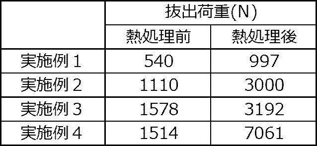
表2に示すように、軸部材の周囲に形成された磁石が磁性材と金属とを含む磁石複合体は、軸部材が磁石から外れた時点の荷重(抜出荷重)が充分に大きく、優れた接合強度を示した。また、熱処理前の成形体に比べて熱処理後の磁石複合体の抜出荷重が大きく、接合強度が向上する傾向を示した。
本明細書に記載された全ての文献、特許出願及び技術規格は、個々の文献、特許出願及び技術規格が参照により取り込まれることが具体的かつ個々に記された場合と同程度に、本明細書中に参照により取り込まれる。
Claims (10)
- 軸部材と、前記軸部材の周囲に配置され、希土類元素を含む磁性材及び金属を含む磁石と、を備える磁石複合体。
- 前記軸部材の表面と前記磁石の表面とが接している、請求項1に記載の磁石複合体。
- 前記金属はビッカース硬さHvが200以下である金属を含む、請求項1又は請求項2に記載の磁石複合体。
- 前記金属はCu及びAlの少なくともいずれかを含む、請求項1~請求項3のいずれか1項に記載の磁石複合体。
- 前記磁性材はSmを含む、請求項1~請求項4のいずれか1項に記載の磁石複合体。
- 希土類元素を含む磁性材粒子及び金属粒子を含む磁石用組成物を準備する工程と、
前記磁石用組成物の成形体を軸部材の周囲に形成する工程と、
前記成形体を酸素存在下で熱処理する工程と、
を有する磁石複合体の製造方法。 - 前記軸部材の表面と前記成形体の表面とが接するように前記成形体が形成される、請求項6に記載の磁石複合体の製造方法。
- 前記金属粒子はビッカース硬さHvが200以下である金属を含む、請求項6又は請求項7に記載の磁石複合体の製造方法。
- 前記金属はCu及びAlの少なくともいずれかを含む、請求項6~請求項8のいずれか1項に記載の磁石複合体の製造方法。
- 前記磁性材粒子はSmを含む、請求項6~請求項9のいずれか1項に記載の磁石複合体の製造方法。
Priority Applications (2)
| Application Number | Priority Date | Filing Date | Title |
|---|---|---|---|
| JP2021518281A JP7294414B2 (ja) | 2019-05-09 | 2019-05-09 | 磁石複合体及び磁石複合体の製造方法 |
| PCT/JP2019/018586 WO2020225910A1 (ja) | 2019-05-09 | 2019-05-09 | 磁石複合体及び磁石複合体の製造方法 |
Applications Claiming Priority (1)
| Application Number | Priority Date | Filing Date | Title |
|---|---|---|---|
| PCT/JP2019/018586 WO2020225910A1 (ja) | 2019-05-09 | 2019-05-09 | 磁石複合体及び磁石複合体の製造方法 |
Publications (1)
| Publication Number | Publication Date |
|---|---|
| WO2020225910A1 true WO2020225910A1 (ja) | 2020-11-12 |
Family
ID=73051055
Family Applications (1)
| Application Number | Title | Priority Date | Filing Date |
|---|---|---|---|
| PCT/JP2019/018586 Ceased WO2020225910A1 (ja) | 2019-05-09 | 2019-05-09 | 磁石複合体及び磁石複合体の製造方法 |
Country Status (2)
| Country | Link |
|---|---|
| JP (1) | JP7294414B2 (ja) |
| WO (1) | WO2020225910A1 (ja) |
Cited By (1)
| Publication number | Priority date | Publication date | Assignee | Title |
|---|---|---|---|---|
| WO2025177640A1 (ja) * | 2024-02-21 | 2025-08-28 | 日本製鉄株式会社 | 油井用金属管及びその油井用金属管の潤滑被膜層を形成するための組成物 |
Citations (5)
| Publication number | Priority date | Publication date | Assignee | Title |
|---|---|---|---|---|
| JPH05260706A (ja) * | 1992-03-10 | 1993-10-08 | Shinko Electric Co Ltd | 回転電機における永久磁石内蔵型回転子の製造方法 |
| JPH06112028A (ja) * | 1992-09-30 | 1994-04-22 | Isuzu Motors Ltd | 焼結磁石 |
| JPH1147979A (ja) * | 1997-07-25 | 1999-02-23 | Meidensha Corp | 異種金属材料の接合方法 |
| JP2005294557A (ja) * | 2004-03-31 | 2005-10-20 | Tdk Corp | 希土類焼結磁石の製造方法 |
| JP2014203922A (ja) * | 2013-04-03 | 2014-10-27 | 株式会社ジェイテクト | 磁石の製造方法および磁石 |
-
2019
- 2019-05-09 JP JP2021518281A patent/JP7294414B2/ja active Active
- 2019-05-09 WO PCT/JP2019/018586 patent/WO2020225910A1/ja not_active Ceased
Patent Citations (5)
| Publication number | Priority date | Publication date | Assignee | Title |
|---|---|---|---|---|
| JPH05260706A (ja) * | 1992-03-10 | 1993-10-08 | Shinko Electric Co Ltd | 回転電機における永久磁石内蔵型回転子の製造方法 |
| JPH06112028A (ja) * | 1992-09-30 | 1994-04-22 | Isuzu Motors Ltd | 焼結磁石 |
| JPH1147979A (ja) * | 1997-07-25 | 1999-02-23 | Meidensha Corp | 異種金属材料の接合方法 |
| JP2005294557A (ja) * | 2004-03-31 | 2005-10-20 | Tdk Corp | 希土類焼結磁石の製造方法 |
| JP2014203922A (ja) * | 2013-04-03 | 2014-10-27 | 株式会社ジェイテクト | 磁石の製造方法および磁石 |
Cited By (1)
| Publication number | Priority date | Publication date | Assignee | Title |
|---|---|---|---|---|
| WO2025177640A1 (ja) * | 2024-02-21 | 2025-08-28 | 日本製鉄株式会社 | 油井用金属管及びその油井用金属管の潤滑被膜層を形成するための組成物 |
Also Published As
| Publication number | Publication date |
|---|---|
| JPWO2020225910A1 (ja) | 2020-11-12 |
| JP7294414B2 (ja) | 2023-06-20 |
Similar Documents
| Publication | Publication Date | Title |
|---|---|---|
| JP6330907B2 (ja) | 希土類磁石成形体の製造方法 | |
| JP6361813B2 (ja) | R−t−b系焼結磁石の製造方法 | |
| JP5293662B2 (ja) | 希土類磁石及び回転機 | |
| US11476020B2 (en) | Rare earth magnet and production method thereof | |
| JP6447380B2 (ja) | 比抵抗が大きいSmFeN系のメタルボンド磁石成形体 | |
| JP6044866B2 (ja) | R−t−b系焼結磁石の製造方法 | |
| CN104112559A (zh) | R-t-b系烧结磁铁 | |
| JP2011042837A (ja) | 磁気異方性磁石素材及びその製造方法 | |
| JP2013149862A (ja) | 希土類磁石の製造方法 | |
| JP2018041777A (ja) | メタルボンド磁石およびその製造方法 | |
| JP6645306B2 (ja) | R−t−b系焼結磁石 | |
| JP6613730B2 (ja) | 希土類磁石の製造方法 | |
| JP2020155545A (ja) | 希土類磁石の製造方法 | |
| JP6523778B2 (ja) | 圧粉磁心、及び圧粉磁心の製造方法 | |
| JP7537536B2 (ja) | R-t-b系焼結磁石 | |
| JP7294414B2 (ja) | 磁石複合体及び磁石複合体の製造方法 | |
| JP6972886B2 (ja) | R−t−b系焼結磁石及びその製造方法 | |
| JP5471678B2 (ja) | 希土類磁石及び回転機 | |
| JP2014192460A (ja) | R−t−x系圧粉磁石の製造方法、及びr−t−x系圧粉磁石 | |
| JP7294413B2 (ja) | 希土類非焼結磁石 | |
| JP2017011073A (ja) | 圧粉磁心、及び圧粉磁心の製造方法 | |
| JP7180615B2 (ja) | 希土類メタルボンド磁石の製造方法及び希土類メタルボンド磁石 | |
| JP7156003B2 (ja) | 希土類磁石の製造方法及び希土類磁石 | |
| WO2020208721A1 (ja) | 希土類非焼結磁石の製造方法及び希土類非焼結磁石 | |
| US12119170B2 (en) | Method for producing a magnetic powder |
Legal Events
| Date | Code | Title | Description |
|---|---|---|---|
| 121 | Ep: the epo has been informed by wipo that ep was designated in this application |
Ref document number: 19927631 Country of ref document: EP Kind code of ref document: A1 |
|
| WWE | Wipo information: entry into national phase |
Ref document number: 2021518281 Country of ref document: JP |
|
| NENP | Non-entry into the national phase |
Ref country code: DE |
|
| 122 | Ep: pct application non-entry in european phase |
Ref document number: 19927631 Country of ref document: EP Kind code of ref document: A1 |