WO2020218247A1 - 空気清浄機および空気清浄機の製造方法 - Google Patents
空気清浄機および空気清浄機の製造方法 Download PDFInfo
- Publication number
- WO2020218247A1 WO2020218247A1 PCT/JP2020/017071 JP2020017071W WO2020218247A1 WO 2020218247 A1 WO2020218247 A1 WO 2020218247A1 JP 2020017071 W JP2020017071 W JP 2020017071W WO 2020218247 A1 WO2020218247 A1 WO 2020218247A1
- Authority
- WO
- WIPO (PCT)
- Prior art keywords
- electrode
- electrode structure
- plate
- cavity
- air purifier
- Prior art date
- Legal status (The legal status is an assumption and is not a legal conclusion. Google has not performed a legal analysis and makes no representation as to the accuracy of the status listed.)
- Ceased
Links
Images


Classifications
-
- F—MECHANICAL ENGINEERING; LIGHTING; HEATING; WEAPONS; BLASTING
- F24—HEATING; RANGES; VENTILATING
- F24F—AIR-CONDITIONING; AIR-HUMIDIFICATION; VENTILATION; USE OF AIR CURRENTS FOR SCREENING
- F24F8/00—Treatment, e.g. purification, of air supplied to human living or working spaces otherwise than by heating, cooling, humidifying or drying
- F24F8/30—Treatment, e.g. purification, of air supplied to human living or working spaces otherwise than by heating, cooling, humidifying or drying by ionisation
-
- A—HUMAN NECESSITIES
- A61—MEDICAL OR VETERINARY SCIENCE; HYGIENE
- A61L—METHODS OR APPARATUS FOR STERILISING MATERIALS OR OBJECTS IN GENERAL; DISINFECTION, STERILISATION OR DEODORISATION OF AIR; CHEMICAL ASPECTS OF BANDAGES, DRESSINGS, ABSORBENT PADS OR SURGICAL ARTICLES; MATERIALS FOR BANDAGES, DRESSINGS, ABSORBENT PADS OR SURGICAL ARTICLES
- A61L9/00—Disinfection, sterilisation or deodorisation of air
- A61L9/16—Disinfection, sterilisation or deodorisation of air using physical phenomena
- A61L9/22—Ionisation
-
- F—MECHANICAL ENGINEERING; LIGHTING; HEATING; WEAPONS; BLASTING
- F24—HEATING; RANGES; VENTILATING
- F24F—AIR-CONDITIONING; AIR-HUMIDIFICATION; VENTILATION; USE OF AIR CURRENTS FOR SCREENING
- F24F7/00—Ventilation
- F24F7/003—Ventilation in combination with air cleaning
-
- F—MECHANICAL ENGINEERING; LIGHTING; HEATING; WEAPONS; BLASTING
- F24—HEATING; RANGES; VENTILATING
- F24F—AIR-CONDITIONING; AIR-HUMIDIFICATION; VENTILATION; USE OF AIR CURRENTS FOR SCREENING
- F24F8/00—Treatment, e.g. purification, of air supplied to human living or working spaces otherwise than by heating, cooling, humidifying or drying
- F24F8/10—Treatment, e.g. purification, of air supplied to human living or working spaces otherwise than by heating, cooling, humidifying or drying by separation, e.g. by filtering
- F24F8/192—Treatment, e.g. purification, of air supplied to human living or working spaces otherwise than by heating, cooling, humidifying or drying by separation, e.g. by filtering by electrical means, e.g. by applying electrostatic fields or high voltages
-
- F—MECHANICAL ENGINEERING; LIGHTING; HEATING; WEAPONS; BLASTING
- F24—HEATING; RANGES; VENTILATING
- F24F—AIR-CONDITIONING; AIR-HUMIDIFICATION; VENTILATION; USE OF AIR CURRENTS FOR SCREENING
- F24F8/00—Treatment, e.g. purification, of air supplied to human living or working spaces otherwise than by heating, cooling, humidifying or drying
- F24F8/20—Treatment, e.g. purification, of air supplied to human living or working spaces otherwise than by heating, cooling, humidifying or drying by sterilisation
-
- H—ELECTRICITY
- H01—ELECTRIC ELEMENTS
- H01T—SPARK GAPS; OVERVOLTAGE ARRESTERS USING SPARK GAPS; SPARKING PLUGS; CORONA DEVICES; GENERATING IONS TO BE INTRODUCED INTO NON-ENCLOSED GASES
- H01T19/00—Devices providing for corona discharge
-
- H—ELECTRICITY
- H01—ELECTRIC ELEMENTS
- H01T—SPARK GAPS; OVERVOLTAGE ARRESTERS USING SPARK GAPS; SPARKING PLUGS; CORONA DEVICES; GENERATING IONS TO BE INTRODUCED INTO NON-ENCLOSED GASES
- H01T23/00—Apparatus for generating ions to be introduced into non-enclosed gases, e.g. into the atmosphere
Definitions
- the present invention relates to an air purifier that generates ionized wind and a method for manufacturing an air purifier.
- the present invention relates to an air purifier that generates ionized air without a fan and a method for manufacturing an air purifier.
- a device that generates ionic wind by corona discharge has been known.
- a first metal layer having a first cavity pattern and a second metal layer having a second cavity pattern different from the first cavity pattern are laminated with a gap, and a first voltage is supplied to them.
- a potential difference is generated between the rod-shaped electrodes arranged on the central axis of the first and second cavity patterns, and ion wind is generated by corona discharge.
- ionic wind is generated by corona discharge, but it is desired to increase the amount of ionic wind, and a device provided with a plurality of the above electrodes is also known.
- the first metal layer and the second metal layer are laminated so that the first cavity pattern and the second cavity pattern are coaxial.
- a spacer is sandwiched between them and fixed with a pin or the like (see Patent Document 1).
- such assembly work is an obstacle in increasing the number of manufacturing processes and reducing the manufacturing time and cost.
- the distal portions of the plurality of rod-shaped electrodes from the first and second cavity patterns have a flat plate structure, and the flat plate thereof. It has been proposed to facilitate manufacturing by supporting the structure with a flat plate as a base.
- the air purifier 1 is a first electrode portion 10 having a plurality of first electrode structures 12, as shown in FIGS. 1 and 2, for example.
- first electrode structure 12 a substantially circular first cavity 14 and a substantially annular second cavity 16 coaxial with the first cavity 14 are formed, and the first cavity 14 and the second cavity 14 are formed.
- a plate-shaped first electrode portion 10 having a substantially annular first conductor region 18 between the cavity 16 and a second electrode portion 20 having a plurality of second electrode structures 22.
- a third cavity 24 having a diameter larger than that of the first cavity 14 and a substantially circular third cavity 24 and a substantially annular fourth cavity 26 coaxial with the third cavity 24 are formed, and the third cavity is formed.
- a plate-like second conductor region 28 having a substantially annular shape is provided between the cavity 24 and the fourth cavity 26, and the plurality of second electrode structures 22 are formed at positions corresponding to the first electrode structure 12.
- the second electrode portion 20 of the above, the first electrode portion 10 and the second electrode portion 20 are connected, and the first electrode portion 10 and the second electrode portion 20 are laminated coaxially with the first electrode structure 12 and the second electrode structure 22.
- first electrode plate 100 formed of a conductor plate having a connecting portion 50 having a bent shape so as to; a second electrode arranged at a position separated from the first electrode structure 12 and the second electrode structure 22.
- a plurality of third electrode structures 32 extending toward the first electrode structure 12 and the second electrode structure 22 are integrally formed on the central axes of the first electrode structure 12 and the second electrode structure 22.
- a second electrode plate 200 formed and formed of a conductor plate is provided; a first electrode structure 12, a second electrode structure 22, and a third electrode structure 32 are arranged in this order, and a negative voltage is applied to the first electrode plate 100.
- a corona discharge is generated between the first electrode structure 12 and the third electrode structure 32, and the second electrode structure 22 and the third electrode structure 32.
- An ionic wind F is generated from the first electrode structure 12 and the second electrode structure 22 in the direction away from the third electrode structure 32.
- a corona discharge is generated between the first electrode structure and the third electrode structure, and between the second electrode structure and the third electrode structure to generate the first electrode structure and the second electrode structure 22. Since an ionic wind is generated in a direction away from the third electrode structure 32, a large amount of ionic wind can be generated. Further, a first electrode portion having a plurality of first electrode structures, a second electrode portion having a plurality of second electrode structures, and a connecting portion having a bent shape so as to stack the first electrode portion and the second electrode portion. Is formed on the first electrode plate formed of the conductor plate, so that the air purifier can be easily manufactured with few manufacturing steps.
- the proximal end 33 of the third electrode structure 32 from the second electrode structure 22 is formed in a plane. .. With this configuration, even if the tip of the third electrode structure is touched for maintenance or the like, it is safe because it is flat.
- the distance L1 between the first conductor region 18 of the first electrode structure 12 and the third electrode structure 32 is a second.
- the distance between the second conductor region 28 of the electrode structure 22 and the third electrode structure 32 is longer than the distance L2.
- the distance from the third electrode of the first electrode structure which has a small diameter and high density, is farther than the distance from the third electrode of the second electrode structure, which has a large diameter and low density. Since the corona discharge is weakened, it is easy to blow out ion air with a uniform density as a whole.
- the distance between the first conductor region and the third electrode structure means the shortest distance between them, and the distance between the second conductor region and the third electrode structure means the shortest distance between them.
- the width of the connecting portion 50 is narrower than the width of the first electrode portion 10 and the width of the second electrode portion 20. With this configuration, it is easy to process when the conductor plate for the first electrode plate is bent and the first electrode portion and the second electrode portion are laminated, and the weight of the first electrode plate can be reduced.
- the width of the first electrode portion, the second electrode portion, and the connecting portion is the length in the direction orthogonal to the direction in which the first electrode portion, the connecting portion, and the second electrode portion are arranged before the first electrode plate is bent. It is the length in the vertical direction in FIG.
- the first electrode plate 100 is a fourth electrode portion 40 having a plurality of fourth electrode structures 42.
- a fifth cavity 44 having a diameter larger than that of the third cavity 24 and having a substantially circular shape is formed, and the fourth electrode region 48, which is a conductor region on the periphery of the fifth cavity 44, is formed.
- the plurality of fourth electrode structures 42 are formed at positions corresponding to the second electrode structure 22, and the plate-shaped fourth electrode portion 40, the fourth electrode portion 40, and the second electrode portion 20 are connected to each other.
- the four-electrode structure 42 and the second electrode structure 22 are coaxially provided with a second connecting portion 52 having a bent shape so as to vertically stack the fourth electrode portion 40 and the second electrode portion 20.
- the corona is also between the fourth electrode structure and the third electrode structure. Since a discharge is generated to generate an ionic wind in a direction away from the third electrode structure from the fourth electrode structure, a large amount of ionic wind can be generated.
- the method for manufacturing the air purifier according to the sixth aspect of the present invention is, for example, as shown in FIGS. 2 to 4, the method for manufacturing the air purifier 1 according to any one of the first to fourth aspects.
- the first electrode portion 10, the second electrode portion 20, and the connecting portion 50 are formed by pressing on the plate-shaped conductor plate 110, and the first electrode portion 10, the second electrode portion 20, and the connecting portion 50 are formed.
- the first electrode plate 100 is manufactured by bending the connecting portion 50 of the conductor plate 110. With this configuration, the first electrode plate can be manufactured by press working and bending, so that it is a manufacturing method of an air purifier that has few manufacturing steps and is easy to manufacture.
- a third electrode structure 32 is formed on a plate-shaped conductor plate 210 by press working.
- the second electrode plate can be manufactured by press working, it becomes a manufacturing method of an air purifier that has few manufacturing steps and is easy to manufacture.
- the method for manufacturing the air purifier according to the eighth aspect of the present invention is, for example, as shown in FIGS. 2 to 4, the method for manufacturing the air purifier according to the fifth aspect, and is a plate-shaped conductor plate 110.
- the first electrode portion 10, the second electrode portion 20, the fourth electrode portion 40, the connecting portion 50, and the second connecting portion 52 are formed by pressing, and the first electrode portion 10, the second electrode portion 20, and the second electrode portion 20 are formed.
- the first electrode plate 100 is manufactured by bending the connecting portion 50 and the second connecting portion 52 of the conductor plate 110 in which the electrode portion 40, the connecting portion 50, and the second connecting portion 52 are formed. .. With this configuration, the first electrode plate can be manufactured by press working and bending, so that it is a manufacturing method of an air purifier that has few manufacturing steps and is easy to manufacture.
- a third electrode structure 32 is formed on a plate-shaped conductor plate 210 by press working.
- the second electrode plate can be manufactured by press working, it becomes a manufacturing method of an air purifier that has few manufacturing steps and is easy to manufacture.
- the air purifier of the present invention is an air purifier that can generate a large amount of ionic wind and is easy to manufacture with few manufacturing steps. Further, according to the method for manufacturing an air purifier of the present invention, the method for manufacturing an air purifier has few manufacturing steps and is easy to manufacture.
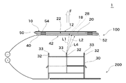
- FIG. 1 is a cross-sectional view of a main part of the air purifier 1.
- the air purifier 1 has, as a main part, a first electrode plate 100 in which a plate-shaped first electrode portion 10, a plate-shaped second electrode portion 20, and a plate-shaped fourth electrode portion 40 are laminated, and these electrodes. It has a second electrode plate 200 having a third electrode structure 32 facing the portion.
- the air purifier 1 fixedly accommodates a power source that applies a negative voltage to the first electrode plate 100 and a positive voltage to the second electrode plate 200, and takes in outside air to take in ion air. It has a blowing casing and a switch for operating and stopping the air purifier 1. In the air purifier 1, the ion air generated at the main part is ejected through a nozzle formed in the casing.
- FIG. 2 is a plan view of the conductor plate 110 press-processed for the first electrode plate 100.
- the conductor plate 110 is typically a metal plate such as iron, copper, or aluminum, but is not limited.
- the conductor plate 110 includes a first electrode portion 10, a second electrode portion 20, a fourth electrode portion 40, a connecting portion 50 connecting the first electrode portion 10 and the second electrode portion 20, and a second electrode portion 20. And the second connecting portion 52 that connects the fourth electrode portion 40 and the fourth electrode portion 40 are pressed.
- a plurality of first electrode structures 12 are formed on the first electrode portion 10.
- the first electrode structure 12 is formed as follows.
- the substantially circular first cavity 14 and the substantially annular second cavity 16 are formed coaxially.
- the substantially circular first cavity 14 is circular, the distance from the third electrode structure 32 becomes uniform, so that a uniform corona discharge can be obtained and the ion wind becomes uniform.
- the substantially circular first cavity 14 may have a polygonal shape, an ellipse shape, a rice ball shape, or the like.
- the substantially annular second cavity 16 is formed coaxially with the first cavity 14 so as to form the first conductor region 18 around the first cavity 14.
- the substantially annular second cavity 16 is, for example, a portion between the three fan-shaped cavities 16a, 16b, 16c and the fan-shaped cavities 16a, 16b, 16c, for supporting the first conductor region 18. It is composed of joint portions 16d, 16e and 16f.
- the number of fan-shaped cavities and joints is not limited to three, and may be two or four or more. In this way, a substantially ring-shaped first conductor region 18 is formed between the first cavity 14 and the second cavity 16.
- the first conductor region 18, especially its inner edge, causes a corona discharge with the third electrode structure 32.
- the first electrode portion 10 has seven first electrode structures 12 on a flat plate. With the plurality of first electrode structures 12 as described above, a large amount of ionic wind can be generated by many corona discharges. Further, the seven first electrode structures 12 are arranged so as to be equidistant from each other. When arranged in this way, a uniform ionic wind can be obtained.
- the number of the first electrode structures 12 is not limited to seven, and can be arbitrarily changed depending on the required amount of ion air, and the arrangement thereof is not limited to equidistant distances.
- the second electrode portion 20 has a structure similar to that of the first electrode portion 10, different points will be described, and duplicate description will be omitted.
- a plurality of second electrode structures 22 are formed on the flat plate in the second electrode portion 20.
- the second electrode structure 22 is formed as follows.
- the substantially circular third cavity 24 corresponding to the first cavity 14 and the substantially annular fourth cavity 26 corresponding to the second cavity 16 are coaxially formed, and the second conductor region 28 is formed. It is formed.
- the third cavity 24 has a larger diameter than the first cavity 14. That is, the second electrode structure 22 has a larger diameter than the first electrode structure 12.
- the substantially annular fourth cavity 26, like the second cavity 16, is a portion between the three fan-shaped cavities and the fan-shaped cavity, and is a joint portion for supporting the second conductor region 28. Consists of.
- the outer diameter of the fourth cavity 26 is the same as the outer diameter of the second cavity 16, but is not necessarily limited to the same diameter. By setting these outer diameters to the same diameter, a smooth path of the ion wind generated by the corona discharge can be constructed.
- the second electrode structure 22 is formed at a position corresponding to the first electrode structure 12.
- the "corresponding position" means that the conductor plate 110 has a positional relationship coaxial with each other when the conductor plate 110 is bent so as to be the first electrode plate 100.
- a plurality of fourth electrode structures 42 are formed on the flat plate in the fourth electrode portion 40.
- the fourth electrode structure 42 is formed as follows.
- a substantially circular fifth cavity 44 is formed.
- the fifth cavity 44 has a larger diameter than the third cavity 24.
- the conductor region on the periphery of the fifth cavity 44 becomes the fourth electrode structure 42. That is, the fourth electrode structure 42 has a larger diameter than the second electrode structure 22.
- the outer diameter of the fifth cavity 44 is the same as the outer diameter of the second cavity 16 and the fourth cavity 26, but is not necessarily limited to the same diameter. By setting these outer diameters to the same diameter, a smooth path of ionic wind generated by corona discharge can be configured.
- the connecting portion 50 is located between the first electrode portion 10 and the second electrode portion 20, and connects the two.
- the connecting portion 50 is a portion that is bent to form the first electrode plate 100 by laminating the first electrode portion 10 and the second electrode portion 20. Therefore, the connecting portion 50 may have a length sufficient to be bent for laminating.
- the width of the connecting portion 50 may be narrower than that of the first electrode portion 10 and the second electrode portion 20. By narrowing the width of the connecting portion 50, the force for bending can be reduced, that is, the bending can be facilitated.
- the "length" is the length in the direction in which the first electrode portion 10, the connecting portion 50, and the second electrode portion 20 are lined up (horizontal direction in FIG. 2), and the "width" is the first.
- the connecting portion 50 is usually formed of the same material as the first electrode portion 10 and the second electrode portion 20, but may be formed of a different material.
- the second connecting portion 52 is located between the second electrode portion 20 and the fourth electrode portion 40, and connects the two. Others are the same as the connecting portion 50, so duplicate description will be omitted.
- FIG. 3 shows a state in which the connecting portion 50 and the second connecting portion 52 are bent in order to laminate the first electrode portion 10, the second electrode portion 20, and the fourth electrode portion 40.
- Four spacers 54 are attached to the surfaces facing the second electrode portion 20.
- the spacer 54 determines the size of the gap between the electrode portions 10, 20 and 40, and can keep the gap constant. Normally, when the conductor plate 110 is pressed, a recess (not shown) for a spacer is formed, and the spacer 54 is fitted into the recess to attach the conductor plate 110.
- the material of the spacer 54 is the same as that of the conductor plate 110 because it is easy to process.
- the material of the spacer 54 may be different from that of the conductor plate 110, and may be a conductor or an insulator.
- FIG. 4 shows a state in which the first electrode portion 10, the second electrode portion 20, and the fourth electrode portion 40 are laminated after the bending process is completed.
- the spacers 54 of the first electrode portion 10 and the second electrode portion 20 and the spacers 54 of the second electrode portion 20 and the fourth electrode portion 40 are in contact with each other to form a gap between the electrode portions 10, 20, and 40. ..
- the first electrode plate 100 can be manufactured by pressing the conductor plate 110 and bending the pressed conductor plate 110, which is easy.
- the first electrode structure 12, the second electrode structure 22, and the second electrode structure are coaxial because they are manufactured by press working and bending work.
- the deviation of the 4-electrode structure 42 can be reduced.
- the second electrode plate 200 is arranged so as to face the first electrode portion 10, the second electrode portion 20, and the fourth electrode portion 40, and functions as a third electrode portion 30 that generates a corona discharge between them.
- the third electrode portion 30 has a plurality of rod-shaped third electrode structures 32 extending on the central axes of the first electrode structure 12, the second electrode structure 22, and the fourth electrode structure 42, respectively.
- the "rod shape” does not necessarily have to be an elongated element having the same diameter, and may be a plate or the like whose width becomes narrower toward the tip, as long as it has a shape capable of generating a corona discharge from the tip. Good.
- the tip 33 of the third electrode structure 32 that is, the proximal ends of the first electrode portion 10, the second electrode portion 20, and the fourth electrode portion 40 on the side is formed in a plane.
- the flat surface referred to here includes a case where the peripheral edge of the tip 33 is rounded or chamfered, or the tip 33 has a smooth rotary elliptical shape (rotating body around a single axis) as a whole.
- FIG. 5 is a plan view of the conductor plate 210 press-processed for the second electrode plate 200.
- a fold line 212 is inserted so that it can be folded three-dimensionally. Due to the folding line 212, the conductor plate 210 has a central portion 34 having three third electrode structures 32, two side portions 35 having two third electrode structures 32, and a central portion 34 and side portions 35.
- FIG. 6 is a five-view view showing the second electrode plate 200 assembled from the conductor plate 210.
- A is a plan view
- (b) is a front view
- (c) is a right side view
- (d) is a rear view
- (e) is a left side view.
- the conductor plate 210 is bent at the folding line 212, and the tip of the brace portion 38 is passed through the through hole 39.
- the shape of the second electrode plate 200 is stabilized by bending the penetrating portion of the brace portion 38 as shown by the broken line in FIG.
- the second electrode plate 200 can be manufactured by pressing the conductor plate into one piece and bending the pressed conductor plate 210, which is easy.
- the second electrode is manufactured by press working and bending.
- the manufacturing process of the plate 200 can be reduced.
- the air purifier 1 is manufactured by fixing and storing the first electrode plate 100 and the second electrode plate 200 manufactured as described above in the casing and connecting them to a power source.
- first electrode plate 100 has been described as having the first electrode portion 10, the second electrode portion 20, and the fourth electrode portion 40, it is not necessary to have the fourth electrode portion 40. Alternatively, the first electrode plate 100 may further have a similar electrode portion.
- first electrode plate 100 and the second electrode plate 200 have been described as being formed by press working together, only one of them may be formed by press working. Even in that case, the manufacturing method is easy and requires fewer manufacturing steps than the conventional manufacturing method.
- the width of the connecting portion 50 and the second connecting portion 52 has been described as being narrower than the width of the first electrode portion 10, the second electrode portion 20, and the fourth electrode portion 40, but one or both of them may be used. It may be about the same as the width of the first electrode portion 10, the second electrode portion 20, and the fourth electrode portion 40.
- the operation of the air purifier 1 will be described.
- a corona discharge is generated between the third electrode structure 32 and the second electrode structure 22, and between the third electrode structure 32 and the fourth electrode structure 42.
- the potential difference to be applied changes depending on the interval and size of the electrode structure.
- ion wind is formed from the first electrode structure 12, the second electrode structure 22, and the fourth electrode structure 42 in the direction away from the third electrode structure 32 (upward in FIG. 1). That is, since air is + ionized in the first electrode structure 12, the second electrode structure 22, and the fourth electrode structure 42, ion wind is generated in the direction away from the third electrode structure 32 to which the positive voltage is applied. Since the ion wind is formed at the first electrode structure 12, the second electrode structure 22 and the fourth electrode structure 42, that is, at three places, a large amount of ion wind flows.
- the distance L1 between the first electrode structure 12 and the third electrode structure 32 is longer than the distance L2 between the second electrode structure 22 and the third electrode structure 32. Further, the distance L4 between the fourth electrode structure 42 and the third electrode structure 32 is made shorter than the distance L2 between the second electrode structure 22 and the third electrode structure 32. The distance L4 between the fourth electrode structure 42 and the third electrode structure 32 means the shortest distance between them.
- the small-diameter first electrode structure 12 has a high-density ion wind
- the larger-diameter second electrode structure 22 has a lower-density ion wind
- the larger-diameter fourth electrode structure 42 has a lower density ion wind. Wind is generated.
- the distance from the third electrode structure 32 is long, the corona discharge is also weakened, so that the ionic wind generated becomes low in density. Therefore, by setting L1> L2> L4, it is easy to generate an ion wind having a uniform density as a whole.
- the distances L1, L2, and L4 are not limited to the above, and may have other relationships or the same distance.
- the air purifier according to the present invention can decompose viruses and chemical substances floating in spaces such as indoor space, vehicle interior space, and container interior space by generating ionized wind, and can sterilize and deodorize air.
- Air purifier 10 1st electrode part 12 1st electrode structure 14 1st cavity 16 2nd cavity 18 1st conductor region 20 2nd electrode part 22 2nd electrode structure 24 3rd cavity 26 4th Cavity 28 2nd conductor region 30 3rd electrode portion 32 3rd electrode structure 33 Tip of 3rd electrode structure (proximal end from 2nd electrode structure) 34 Central part 35 Side part 36 Coupling part 37 Bottom part 38 Brace part 39 Through hole 40 4th electrode part 42 4th electrode structure 44 5th cavity 48 4th conductor region 50 Connecting part 52 2nd connecting part 54 Spacer 60 Through hole for fixing the first electrode plate 100 First electrode plate 110 Plate-shaped conductor plate 200 Second electrode plate F Ion wind L1 Distance between the first electrode structure and the third electrode structure L2 Second electrode structure Distance from the third electrode structure L3 Distance between the fourth electrode structure and the third electrode structure
Landscapes
- Engineering & Computer Science (AREA)
- Health & Medical Sciences (AREA)
- Chemical & Material Sciences (AREA)
- General Engineering & Computer Science (AREA)
- Mechanical Engineering (AREA)
- Combustion & Propulsion (AREA)
- General Health & Medical Sciences (AREA)
- Veterinary Medicine (AREA)
- Public Health (AREA)
- Animal Behavior & Ethology (AREA)
- Life Sciences & Earth Sciences (AREA)
- Epidemiology (AREA)
- Physics & Mathematics (AREA)
- Plasma & Fusion (AREA)
- Electrostatic Separation (AREA)
- Disinfection, Sterilisation Or Deodorisation Of Air (AREA)
Priority Applications (3)
| Application Number | Priority Date | Filing Date | Title |
|---|---|---|---|
| KR1020217033147A KR20220002290A (ko) | 2019-04-23 | 2020-04-20 | 공기 청정기 및 공기 청정기의 제조 방법 |
| US17/602,570 US20220176007A1 (en) | 2019-04-23 | 2020-04-20 | Air purifier and production method for air purifier |
| CN202080029488.4A CN113728524B (zh) | 2019-04-23 | 2020-04-20 | 空气净化器及空气净化器的制造方法 |
Applications Claiming Priority (2)
| Application Number | Priority Date | Filing Date | Title |
|---|---|---|---|
| JP2019-081771 | 2019-04-23 | ||
| JP2019081771A JP6845278B2 (ja) | 2019-04-23 | 2019-04-23 | 空気清浄機および空気清浄機の製造方法 |
Publications (1)
| Publication Number | Publication Date |
|---|---|
| WO2020218247A1 true WO2020218247A1 (ja) | 2020-10-29 |
Family
ID=72942744
Family Applications (1)
| Application Number | Title | Priority Date | Filing Date |
|---|---|---|---|
| PCT/JP2020/017071 Ceased WO2020218247A1 (ja) | 2019-04-23 | 2020-04-20 | 空気清浄機および空気清浄機の製造方法 |
Country Status (5)
| Country | Link |
|---|---|
| US (1) | US20220176007A1 (https=) |
| JP (1) | JP6845278B2 (https=) |
| KR (1) | KR20220002290A (https=) |
| CN (1) | CN113728524B (https=) |
| WO (1) | WO2020218247A1 (https=) |
Cited By (6)
| Publication number | Priority date | Publication date | Assignee | Title |
|---|---|---|---|---|
| US10980911B2 (en) | 2016-01-21 | 2021-04-20 | Global Plasma Solutions, Inc. | Flexible ion generator device |
| US11283245B2 (en) | 2016-08-08 | 2022-03-22 | Global Plasma Solutions, Inc. | Modular ion generator device |
| US11344922B2 (en) | 2018-02-12 | 2022-05-31 | Global Plasma Solutions, Inc. | Self cleaning ion generator device |
| US11581709B2 (en) | 2019-06-07 | 2023-02-14 | Global Plasma Solutions, Inc. | Self-cleaning ion generator device |
| US11695259B2 (en) | 2016-08-08 | 2023-07-04 | Global Plasma Solutions, Inc. | Modular ion generator device |
| US12516836B2 (en) | 2021-08-30 | 2026-01-06 | Global Plasma Solutions, Inc. | Self-cleaning device for generating ions |
Families Citing this family (1)
| Publication number | Priority date | Publication date | Assignee | Title |
|---|---|---|---|---|
| CN115875786B (zh) * | 2021-09-30 | 2026-01-23 | 广东美的制冷设备有限公司 | 离子风组件及具有其的空气处理设备 |
Citations (4)
| Publication number | Priority date | Publication date | Assignee | Title |
|---|---|---|---|---|
| JP2014041754A (ja) * | 2012-08-22 | 2014-03-06 | Mitsubishi Electric Corp | 放電装置及び空気調和機 |
| JP2016123768A (ja) * | 2015-01-06 | 2016-07-11 | 株式会社 片野工業 | イオン・オゾン風発生装置及び方法 |
| WO2018164005A1 (ja) * | 2017-03-07 | 2018-09-13 | エクレール株式会社 | 空気清浄機 |
| JP2019003739A (ja) * | 2017-06-12 | 2019-01-10 | 株式会社Soken | イオン発生装置 |
Family Cites Families (3)
| Publication number | Priority date | Publication date | Assignee | Title |
|---|---|---|---|---|
| JP2895544B2 (ja) | 1990-01-16 | 1999-05-24 | 株式会社日立製作所 | プラント状態表示方法および装置 |
| CN104428012B (zh) * | 2012-06-27 | 2016-11-09 | 松下知识产权经营株式会社 | 放电单元以及使用了其的空气净化装置 |
| WO2017085791A1 (ja) * | 2015-11-17 | 2017-05-26 | 富士電機株式会社 | 電気集塵機および排ガス浄化システム |
-
2019
- 2019-04-23 JP JP2019081771A patent/JP6845278B2/ja active Active
-
2020
- 2020-04-20 WO PCT/JP2020/017071 patent/WO2020218247A1/ja not_active Ceased
- 2020-04-20 US US17/602,570 patent/US20220176007A1/en not_active Abandoned
- 2020-04-20 KR KR1020217033147A patent/KR20220002290A/ko not_active Withdrawn
- 2020-04-20 CN CN202080029488.4A patent/CN113728524B/zh active Active
Patent Citations (4)
| Publication number | Priority date | Publication date | Assignee | Title |
|---|---|---|---|---|
| JP2014041754A (ja) * | 2012-08-22 | 2014-03-06 | Mitsubishi Electric Corp | 放電装置及び空気調和機 |
| JP2016123768A (ja) * | 2015-01-06 | 2016-07-11 | 株式会社 片野工業 | イオン・オゾン風発生装置及び方法 |
| WO2018164005A1 (ja) * | 2017-03-07 | 2018-09-13 | エクレール株式会社 | 空気清浄機 |
| JP2019003739A (ja) * | 2017-06-12 | 2019-01-10 | 株式会社Soken | イオン発生装置 |
Cited By (10)
| Publication number | Priority date | Publication date | Assignee | Title |
|---|---|---|---|---|
| US10980911B2 (en) | 2016-01-21 | 2021-04-20 | Global Plasma Solutions, Inc. | Flexible ion generator device |
| US11980704B2 (en) | 2016-01-21 | 2024-05-14 | Global Plasma Solutions, Inc. | Flexible ion generator device |
| US11283245B2 (en) | 2016-08-08 | 2022-03-22 | Global Plasma Solutions, Inc. | Modular ion generator device |
| US11695259B2 (en) | 2016-08-08 | 2023-07-04 | Global Plasma Solutions, Inc. | Modular ion generator device |
| US12100938B2 (en) | 2016-08-08 | 2024-09-24 | Global Plasma Solutions, Inc. | Modular ion generator device |
| US11344922B2 (en) | 2018-02-12 | 2022-05-31 | Global Plasma Solutions, Inc. | Self cleaning ion generator device |
| US12202014B2 (en) | 2018-02-12 | 2025-01-21 | Global Plasma Solutions, Inc. | Self cleaning ion generator device |
| US11581709B2 (en) | 2019-06-07 | 2023-02-14 | Global Plasma Solutions, Inc. | Self-cleaning ion generator device |
| US12015250B2 (en) | 2019-06-07 | 2024-06-18 | Global Plasma Solutions, Inc. | Self-cleaning ion generator device |
| US12516836B2 (en) | 2021-08-30 | 2026-01-06 | Global Plasma Solutions, Inc. | Self-cleaning device for generating ions |
Also Published As
| Publication number | Publication date |
|---|---|
| JP6845278B2 (ja) | 2021-03-17 |
| US20220176007A1 (en) | 2022-06-09 |
| KR20220002290A (ko) | 2022-01-06 |
| CN113728524A (zh) | 2021-11-30 |
| JP2020178742A (ja) | 2020-11-05 |
| CN113728524B (zh) | 2022-10-18 |
Similar Documents
| Publication | Publication Date | Title |
|---|---|---|
| JP6845278B2 (ja) | 空気清浄機および空気清浄機の製造方法 | |
| JP2020178742A5 (https=) | ||
| JP5185784B2 (ja) | 空気流発生装置 | |
| JP6083568B2 (ja) | 静電霧化装置 | |
| US11318478B2 (en) | Electric discharge device and air purifying device | |
| CN106653555A (zh) | 离子传输聚焦及筛选装置 | |
| JP3210591U (ja) | 空気清浄機 | |
| JPWO2020013144A1 (ja) | 放電装置を装着可能な機器 | |
| JP2017221681A (ja) | 電気外科的プラズマ装置及びシステム | |
| KR101725849B1 (ko) | 광대역 주파수 튜닝이 가능한 선형 가속기 | |
| CN104466687A (zh) | 一种负离子发生装置 | |
| JP2005510023A5 (https=) | ||
| JP2013045531A (ja) | イオン発生装置及びこれを備えた空気清浄装置 | |
| JP2012096127A (ja) | 電気集塵装置 | |
| JP2014110161A (ja) | プラズマ発生装置 | |
| JP7315309B2 (ja) | イオン風生成機の制御方法 | |
| JP5458750B2 (ja) | 送風装置 | |
| WO2006112020A1 (ja) | 除電装置 | |
| JP6015287B2 (ja) | オゾン発生装置 | |
| CN101950929B (zh) | 离子发生元件、离子发生单元及离子发生装置 | |
| JPH0480519B2 (https=) | ||
| JP2022007766A (ja) | 送風装置 | |
| JP6553348B2 (ja) | 送風装置 | |
| US20160196949A1 (en) | Atmospheric ionizer including a source that supplies electrical energy to an ion-generating structure without wires | |
| JP2002164148A (ja) | イオン発生装置 |
Legal Events
| Date | Code | Title | Description |
|---|---|---|---|
| 121 | Ep: the epo has been informed by wipo that ep was designated in this application |
Ref document number: 20795544 Country of ref document: EP Kind code of ref document: A1 |
|
| NENP | Non-entry into the national phase |
Ref country code: DE |
|
| 122 | Ep: pct application non-entry in european phase |
Ref document number: 20795544 Country of ref document: EP Kind code of ref document: A1 |