WO2020218038A1 - 超音波センサ - Google Patents
超音波センサ Download PDFInfo
- Publication number
- WO2020218038A1 WO2020218038A1 PCT/JP2020/016205 JP2020016205W WO2020218038A1 WO 2020218038 A1 WO2020218038 A1 WO 2020218038A1 JP 2020016205 W JP2020016205 W JP 2020016205W WO 2020218038 A1 WO2020218038 A1 WO 2020218038A1
- Authority
- WO
- WIPO (PCT)
- Prior art keywords
- ultrasonic
- bottom plate
- plate portion
- ultrasonic sensor
- ultrasonic element
- Prior art date
- Legal status (The legal status is an assumption and is not a legal conclusion. Google has not performed a legal analysis and makes no representation as to the accuracy of the status listed.)
- Ceased
Links
Images

Classifications
-
- G—PHYSICS
- G01—MEASURING; TESTING
- G01S—RADIO DIRECTION-FINDING; RADIO NAVIGATION; DETERMINING DISTANCE OR VELOCITY BY USE OF RADIO WAVES; LOCATING OR PRESENCE-DETECTING BY USE OF THE REFLECTION OR RERADIATION OF RADIO WAVES; ANALOGOUS ARRANGEMENTS USING OTHER WAVES
- G01S15/00—Systems using the reflection or reradiation of acoustic waves, e.g. sonar systems
- G01S15/88—Sonar systems specially adapted for specific applications
- G01S15/93—Sonar systems specially adapted for specific applications for anti-collision purposes
- G01S15/931—Sonar systems specially adapted for specific applications for anti-collision purposes of land vehicles
-
- G—PHYSICS
- G01—MEASURING; TESTING
- G01S—RADIO DIRECTION-FINDING; RADIO NAVIGATION; DETERMINING DISTANCE OR VELOCITY BY USE OF RADIO WAVES; LOCATING OR PRESENCE-DETECTING BY USE OF THE REFLECTION OR RERADIATION OF RADIO WAVES; ANALOGOUS ARRANGEMENTS USING OTHER WAVES
- G01S7/00—Details of systems according to groups G01S13/00, G01S15/00, G01S17/00
- G01S7/52—Details of systems according to groups G01S13/00, G01S15/00, G01S17/00 of systems according to group G01S15/00
- G01S7/521—Constructional features
-
- H—ELECTRICITY
- H04—ELECTRIC COMMUNICATION TECHNIQUE
- H04R—LOUDSPEAKERS, MICROPHONES, GRAMOPHONE PICK-UPS OR LIKE ACOUSTIC ELECTROMECHANICAL TRANSDUCERS; DEAF-AID SETS; PUBLIC ADDRESS SYSTEMS
- H04R1/00—Details of transducers, loudspeakers or microphones
- H04R1/02—Casings; Cabinets ; Supports therefor; Mountings therein
-
- G—PHYSICS
- G01—MEASURING; TESTING
- G01S—RADIO DIRECTION-FINDING; RADIO NAVIGATION; DETERMINING DISTANCE OR VELOCITY BY USE OF RADIO WAVES; LOCATING OR PRESENCE-DETECTING BY USE OF THE REFLECTION OR RERADIATION OF RADIO WAVES; ANALOGOUS ARRANGEMENTS USING OTHER WAVES
- G01S15/00—Systems using the reflection or reradiation of acoustic waves, e.g. sonar systems
- G01S15/88—Sonar systems specially adapted for specific applications
- G01S15/93—Sonar systems specially adapted for specific applications for anti-collision purposes
- G01S15/931—Sonar systems specially adapted for specific applications for anti-collision purposes of land vehicles
- G01S2015/937—Sonar systems specially adapted for specific applications for anti-collision purposes of land vehicles sensor installation details
- G01S2015/938—Sonar systems specially adapted for specific applications for anti-collision purposes of land vehicles sensor installation details in the bumper area
Definitions
- This disclosure relates to an ultrasonic sensor.
- An ultrasonic sensor that transmits ultrasonic waves as exploration waves to the outside and receives the reflected waves is used, for example, in an object detection device mounted on a vehicle.
- This type of ultrasonic sensor has a bottomed tubular case and a piezoelectric element attached to the inner bottom of the case.
- a structure in which one ultrasonic sensor has a plurality of resonance frequencies has been studied, and examples thereof include those described in Patent Document 1.
- the ultrasonic sensor described in Patent Document 1 includes two bottomed tubular cases of different sizes and a piezoelectric element, and has a small bottomed tubular case opening on the inner bottom surface of the large bottomed tubular case.
- a piezoelectric element is attached to the outer bottom surface of a small bottomed tubular case. Then, in this ultrasonic sensor, when transmitting or receiving ultrasonic waves, the bottom surface of the large and small bottomed tubular case may be bent in the same direction or in the opposite direction, so that a plurality of resonance frequencies may be generated. It has a structure with.
- this ultrasonic sensor has a structure in which large and small bottomed tubular cases are bonded together, which may greatly reduce durability and increase the manufacturing cost.
- the present disclosure relates to an ultrasonic sensor having a plurality of resonance frequencies while ensuring durability.
- the ultrasonic sensor has an ultrasonic element that converts an electric signal and ultrasonic vibration, and an element accommodating case that has a bottomed tubular shape and accommodates the ultrasonic element inside.
- the element accommodating case has a cylindrical side plate portion that surrounds the directional central axis and a bottom plate portion that closes one end side of the side plate portion in the axial direction parallel to the directional central axis.
- the sound wave element is attached to the bottom plate part, and the part of the bottom plate part located inside the outer shell of the ultrasonic element when viewed from the directional central axis is a space because a part of it is separated from the ultrasonic element. Is formed.
- the ultrasonic sensor has two vibration propagation paths, one is when the vibration from the ultrasonic element propagates directly to the bottom plate portion of the element housing case, and the other is when the vibration propagates to the bottom plate portion through the space. Become. Therefore, a plurality of vibration modes are generated, and one ultrasonic sensor having a plurality of resonance frequencies is obtained. Further, it is not necessary to bond another member between the element accommodating case and the ultrasonic element, the durability is improved, and the manufacturing cost thereof is suppressed.
- the ultrasonic sensor 1 according to the embodiment will be described.
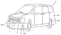
- the ultrasonic sensor 1 is suitable for use in, for example, an object detection device mounted on a vehicle such as an automobile, but is not limited to this, and can be applied to other uses.
- an example applied to an in-vehicle object detection device will be described as a typical example.
- the ultrasonic sensor 1 is mounted on a vehicle V having a box-shaped vehicle body V1. Specifically, the ultrasonic sensor 1 is attached to the front bumper V2 mounted on the front end portion of the vehicle body V1 and the rear bumper V3 mounted on the rear end portion.
- the front bumper V2 and the rear bumper V3 are formed with mounting holes V4, which are through holes for mounting the ultrasonic sensor 1.
- the ultrasonic sensor 1 mounted on the front bumper V2 and the rear bumper V3 is a so-called in-vehicle clearance sonar.
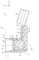
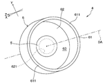
- the XYZ Cartesian coordinate system is set so that the Z axis is parallel to the directional center axis DA of the ultrasonic sensor 1 as shown in FIG.
- the direction parallel to the directional central axis DA is referred to as "axial direction".
- the upper side in FIG. 2, that is, the Z-axis positive direction side may be referred to as the "tip side” in the axial direction.
- the lower side in FIG. 2, that is, the negative direction side of the Z axis may be referred to as the "base end side” in the axial direction.
- any direction orthogonal to the axial direction may be referred to as an "in-plane direction”.
- the "in-plane direction" is the direction parallel to the XY plane in FIG.
- the XYZ coordinate system corresponding to the XYZ Cartesian coordinate system of FIG. 2 is shown, and the outer shell of the recess 621 covered with the ultrasonic element 5 described later and invisible is shown by a broken line.
- the ultrasonic sensor 1 includes a sensor case 2, an elastic holding member 3, and an ultrasonic microphone 4.
- the ultrasonic microphone 4 includes an ultrasonic element 5 and an element accommodating case 6.
- the sensor case 2 is a housing of the ultrasonic sensor 1 and is configured to hold the elastic holding member 3.
- the sensor case 2 includes a case main body portion 21, a connector portion 22, and a case cylinder portion 23.
- each of these parts is integrally formed of a hard synthetic resin such as polypropylene.
- the case main body 21 is a box-shaped portion having a substantially rectangular parallelepiped outer shape, and is formed in a bottomed tubular shape in which the base end side in the axial direction opens.
- the connector portion 22 extends outward from the side wall portion of the case main body portion 21 in order to electrically connect the ultrasonic sensor 1 to an external device such as an electronic control unit.
- the case cylinder portion 23 is a substantially cylindrical portion, and projects from the case main body portion 21 to the tip end side in the axial direction.
- the case cylinder portion 23 is configured to hold the base end portion in the axial direction of the elastic holding member 3 formed in a substantially cylindrical shape centered on the directional center axis DA.
- the cylinder-shaped space inside the case cylinder portion 23 is provided so as to communicate with the substantially rectangular parallelepiped space inside the case main body portion 21.
- the space inside the case cylinder 23 and the space inside the case body 21 are collectively referred to as “the space inside the sensor case 2”.
- the circuit board 24, the wiring portion 25, and the shield portion 26 are housed in the space inside the sensor case 2.
- the circuit board 24 that controls the operation of the ultrasonic sensor 1 is housed in the case main body 21.
- the wiring portion 25 is provided so as to electrically connect the ultrasonic microphone 4 and the circuit board 24.
- the shield portion 26 is fixed to the inner surface of the sensor case 2 so as to electromagnetically shield the circuit board 24 and the wiring portion 25 by covering them.
- the damper member 27 is a disk-shaped member and has an outer diameter corresponding to the inner diameter of the elastic holding member 3. That is, the damper member 27 is fitted in the cylinder-shaped space inside the elastic holding member 3 on the proximal end side of the ultrasonic microphone 4 in the axial direction.
- the damper member 27 is provided so as to suppress vibration transmission from the ultrasonic microphone 4 to the sensor case 2.
- the damper member 27 is formed of, for example, a foamed elastic body such as foamed silicone having insulating properties and elasticity.
- the space inside the sensor case 2 is filled with a filler 28.
- the filler 28 is formed of, for example, a synthetic resin material such as silicone rubber having insulating properties and elasticity.
- the elastic holding member 3 is formed of a synthetic resin-based elastic material such as silicone rubber having insulating properties and elasticity. Synthetic resin-based elastic materials are also referred to as "viscoelastic materials" or “elastomers”.
- the elastic holding member 3 is configured to elastically support the ultrasonic microphone 4 by covering the proximal end side while exposing the distal end side in the axial direction of the ultrasonic microphone 4.
- the ultrasonic microphone 4 is composed of an ultrasonic element 5 and an element accommodating case 6, and has a function as an ultrasonic transmitter / receiver. That is, the ultrasonic microphone 4 is configured to be capable of transmitting and receiving ultrasonic waves.
- the ultrasonic microphone 4 is configured to transmit the exploration wave along the directional central axis DA based on the applied drive signal.
- the directivity central axis DA is a virtual half-line extending from the ultrasonic microphone 4 along the transmission / reception direction of ultrasonic waves, and serves as a reference for the directivity angle.
- the "directed central axis" may also be referred to as the "detection axis”.
- the ultrasonic microphone 4 is configured to receive a reflected wave from an object existing in the surroundings and generate a received signal.
- the ultrasonic element 5 is configured to convert an electric signal and ultrasonic vibration.
- the ultrasonic element 5 is, for example, a piezoelectric element, and has a thin film shape having a thickness direction in the axial direction.
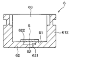
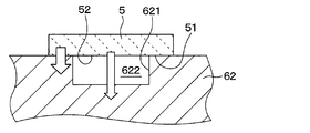
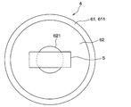
- the ultrasonic element 5 is attached to the inner surface of the bottom plate portion 62 described later in the element accommodating case 6 having a bottomed tubular shape.
- the inner surface of the bottom plate portion 62 is a surface surrounded by the side plate portion 61, which will be described later.
- the ultrasonic element 5 is arranged so as to cover the recess 621 formed in the bottom plate portion 62, for example, as shown in FIG. 4, and the first space 622 is provided together with the recess 621. It is configured.
- the ultrasonic element 5 has a contact portion 51, which is a portion attached to the bottom plate portion 62, and a non-contact portion 52, which is the remaining portion, on a sticking surface which is a surface facing the bottom plate portion 62. It can be said that the non-contact portion 52 is a portion that is not attached to the bottom plate portion 62.
- the non-contact portion 52 causes two paths having different propagation velocities of vibration from the ultrasonic element 5 to the bottom plate portion 62, as shown by a white arrow in FIG. 5, for example, and the ultrasonic sensor 1 resonates a plurality of resonances. It is provided to have a frequency.
- the vibration propagation paths include a first propagation path in which the vibration propagates directly from the ultrasonic element 5 to the bottom plate portion 62, and a second propagation path in which the vibration propagates from the ultrasonic element 5 to the bottom plate portion 62 via the first space 622. There are two propagation paths. The effect of having such a configuration will be described later.
- the non-contact portion 52 preferably occupies an area of the contact portion 51 or more, in other words, occupies 50% or more of the sticking surface.
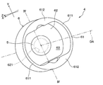
- the element accommodating case 6 has a bottomed tubular shape centered on the directional central axis DA, and has a configuration in which a second space 63 capable of accommodating the ultrasonic element 5 is provided inside.
- the element accommodating case 6 includes a side plate portion 61 and a bottom plate portion 62, which are made of the same material.
- the element accommodating case 6 is seamlessly and integrally formed of a metal such as aluminum.
- the side plate portion 61 has, for example, a cylindrical shape that surrounds the directional central axis DA and has a central axis that is substantially parallel to the directional central axis DA.
- the side plate portion 61 has a thin-walled portion 611 and a thick-walled portion 612.
- the thin-walled portion 611 has a partial cylindrical shape having a predetermined thickness in the radial direction orthogonal to the directional central axis DA.
- the "diameter direction" is a direction extending radially from the directional central axis DA. That is, the radial direction is the radial direction of the virtual circle when a virtual circle centered on the intersection of the plane and the directional center axis DA is drawn on a plane having the directional center axis DA as a normal. ..
- the radial dimension in each portion of the side plate portion 61 may be referred to as "thickness".
- the thin-walled portion 611 has a constant thickness that is thinner than the thick-walled portion 612.
- the predetermined thickness of the thin-walled portion 611 has, for example, the dimension closest to the thickness of the bottom plate portion 62 in the axial direction among the radial or axial dimensions of the side plate portion 61 and the bottom plate portion 62.
- the thin-walled portion 611 has a thickness of the bottom plate portion 62, that is, 0.3 to 2.0 times, preferably 0.5 to 1.5 times, more preferably 0.7 to 1. It is formed to be twice as thick.
- the thin portion 611 can be formed to have substantially the same thickness as the bottom plate portion 62.
- the thick portion 612 has a larger thickness, that is, a radial dimension than the thin portion 611. Specifically, in the present embodiment, the thick portion 612 has a bow shape surrounded by strings and arcs extending along the X-axis direction when viewed from a line of sight parallel to the directional central axis DA. Is formed in. Further, the thick portion 612 is arranged adjacent to the thin portion 611 in the circumferential direction surrounding the directional central axis DA. The "circumferential direction" is the circumferential direction of the above virtual circle.
- the pair of thin-walled portions 611 are arranged so as to face each other with the directional central axis DA interposed therebetween.
- the pair of thick-walled portions 612 are arranged so as to face each other with the directional center axis DA interposed therebetween. That is, in the present embodiment, the second space 63 has a rounded rectangular shape or an oval shape composed of a pair of semicircles and a pair of line segments when viewed from a line of sight parallel to the directional central axis DA. It is formed.
- the side plate portion 61 has a pair of thin-walled portions 611 provided corresponding to a semicircle and a pair of thick-walled portions 612 provided corresponding to a line segment.
- the ultrasonic microphone 4 is configured to have a directivity angle narrower in the Y-axis direction than in the X-axis direction. Since the thick portion 612 can be designed as a portion for adjusting the directivity of ultrasonic waves, it can also be referred to as a "directivity adjusting portion".
- the bottom plate portion 62 is a flat plate-shaped or thin plate-shaped portion having a thickness direction in the axial direction, and is provided so as to close one end side of the side plate portion 61 in the axial direction. Specifically, the bottom plate portion 62 is seamlessly and integrally connected to the tip portion of the side plate portion 61 in the axial direction. As shown in FIG. 3, the bottom plate portion 62 has an outer edge portion coupled to the side plate portion 61 at a fixed end when the ultrasonic element 5 is attached to the bottom plate portion 62 when transmitting or receiving ultrasonic waves by the ultrasonic element 5. It is configured to ultrasonically vibrate in the axial direction while bending.
- a recess 621 is provided on the inner side surface of the bottom plate portion 62, that is, the surface on the second space 63 side in which the ultrasonic element 5 is housed.
- the recess 621 is, for example, a syringe-shaped groove, and is formed by an arbitrary process such as a cutting process.
- the recess 621 is entirely covered with the ultrasonic element 5. That is, as shown in FIG. 3, the portion of the bottom plate portion 62 located inside the outer shell of the ultrasonic element 5 when viewed from the directional central axis DA, that is, the inner portion of the outer shell, is partly the ultrasonic element 5.
- the first space 622 is formed by separating them.
- the inner portion of the outer shell of the bottom plate portion 62 is provided with the recess 621 so that the first space 622 is provided between the bottom plate portion 62 and the ultrasonic element 5.
- the first space 622 formed by the recess 621 and the ultrasonic element 5 is filled with a medium having a vibration propagation velocity different from that of the material constituting the bottom plate portion 62, such as air or silicone.
- the first space 622 is filled with a substance different from the material constituting the bottom plate portion 62.
- the above is the basic configuration of the ultrasonic sensor 1 of the present embodiment.
- the ultrasonic element 5 vibrates ultrasonically when an electric signal is input from a wiring (not shown).
- the ultrasonic element 5 ultrasonically vibrates, the element accommodating case 6 is excited by the vibration.
- the ultrasonic microphone 4 composed of the ultrasonic element 5 and the element accommodating case 6 vibrates in a predetermined vibration mode.
- the bottom plate portion 62 is provided with a recess 621, and the ultrasonic element 5 is attached so as to cover the recess 621.
- the first space 622 formed by the recess 621 is filled with a medium whose propagation speed of vibration from the ultrasonic element 5 is different from that of the material constituting the bottom plate portion 62.
- the ultrasonic microphone 4 has a first vibration mode caused by the vibration from the ultrasonic element 5 propagating directly to the bottom plate portion 62. Further, in addition to the first vibration mode, the ultrasonic microphone 4 has a second vibration mode caused by the vibration from the ultrasonic element 5 propagating to the bottom plate portion 62 via the first space 622. Occurs. As a result, in addition to the first structural resonance frequency due to the first vibration mode, the second structural resonance frequency due to the generation of the second vibration mode is generated. It should be noted that the first structure resonance frequency and the second structure resonance frequency are in such a relationship that one does not become a higher-order resonance frequency of the other.
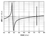
- the result shown in FIG. 6 was obtained for the acoustic impedance characteristic of the ultrasonic microphone 4 shown in FIG.
- two remarkable structural resonance frequencies are generated in the range of 40 to 80 kHz.
- One structural resonance frequency generated at about 48 kHz corresponds to the first vibration mode described above.
- the other structural resonance frequency generated at about 73 kHz is due to the generation of the second vibration mode described above.
- the other structural resonance frequency is presumed to be due to the combination of the vibration wave in the first vibration mode and the vibration in the second vibration mode.
- the recess 621 has a predetermined size and shape so as to remarkably generate a first structure resonance frequency and a second structure resonance frequency in which one does not become a higher-order resonance frequency of the other.
- the outer shape of the recess 621 is not limited to a substantially columnar shape, but may be a substantially polygonal columnar shape, a substantially elliptical columnar shape, or the like, or may have any other shape.
- one ultrasonic microphone 4 can have a plurality of structural resonance frequencies by a simple shape change of providing a recess 621 on the inner surface of the bottom plate portion 62. Further, as compared with the conventional structure in which two bottomed tubular cases of different sizes are bonded together, it is possible to obtain the effect of suppressing a decrease in durability and an increase in cost. Therefore, it is one ultrasonic sensor 1 having a configuration having a plurality of resonance frequencies while ensuring durability.
- the element accommodating case 6 may have a side plate portion 61 composed of only a thin-walled portion 611. Even with such a structure, the effect of having a plurality of resonance frequencies can be obtained by forming the recess 621 in the bottom plate portion 62 and arranging the ultrasonic element 5 on the recess 621.
- the ultrasonic microphone 4 has a structure in which the ultrasonic element 5 covers only a part of the recess 621, that is, a structure in which the first space 622 and the second space 63 communicate with each other. May be done. Even with such a structure, the ultrasonic sensor 1 has a plurality of resonance frequencies as in the above embodiment. Note that FIG. 8 shows a plan view when the ultrasonic microphone 4 is viewed from the directional central axis, and a broken line indicates a portion of the outer shell of the recess 621 that cannot be visually recognized by the ultrasonic element 5.
- the recess 621 may have a groove shape having a wedge shape in cross section as shown in FIG.
- the outer shape of the recess 621 is, for example, conical or polygonal pyramid in cross-sectional view. That is, the recess 621 may have a shape in which the ultrasonic microphone 4 has a first space 622 as a second propagation path of vibration from the ultrasonic element 5, and the shape is not limited to the above embodiment. , May be changed as appropriate.
- the depth in the first space 622 differs depending on the location due to the shape of the recess 621 described above, so that an ultrasonic sensor having three or more resonance frequencies can be obtained.
- the concave portion 621 may have a cross-sectional shape not only a wedge shape but also a shape having a plurality of points having different depths, for example, a shape having a plurality of steps, and the shape is arbitrary. .. Further, since the recess 621 has a shape having a different depth, the effect of expanding the resonance band can also be produced.
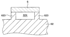
- the bottom plate portion 62 may have a shape having a frame-shaped or partial frame-shaped convex portion 623 on the inner side surface thereof instead of the concave portion 621.
- the ultrasonic element 5 is attached to the tip surface of the convex portion 623, and together with the region inside the convex portion 623 having a substantially frame shape, constitutes the third space 624.
- the inner portion of the outer shell of the bottom plate portion 62 is provided with a substantially frame-shaped convex portion 623, and the ultrasonic element 5 is attached to the tip surface of the convex portion 623 so that the ultrasonic element 5 is placed between the bottom plate portion 62 and the ultrasonic element 5. It is configured to have a third space 624.
- the convex portion 623 has a predetermined size and shape so as to remarkably generate a first structural resonance frequency and a second structural resonance frequency in which one does not become a higher-order resonance frequency of the other.
- the third space 624 may be a closed space that is not connected to the second space 63 by the ultrasonic element 5, or is a space that communicates with the second space 63 as in the second modification described above. There may be.
- the ultrasonic sensor 1 is not limited to a configuration capable of transmitting and receiving ultrasonic waves, and may have a configuration capable of only transmitting ultrasonic waves.
- the ultrasonic sensor 1 may be configured to have only a function of receiving the reflected wave of the exploration wave, which is an ultrasonic wave transmitted from another ultrasonic transmitter, by an object existing in the surroundings. That is, the ultrasonic microphone 4 may be for transmission / reception, transmission, or reception.
- the external shape of the ultrasonic microphone 4, that is, the element accommodating case 6 is not limited to a substantially cylindrical shape, and may be a substantially regular hexagonal columnar shape, a substantially regular octagonal columnar shape, or the like.
- the ultrasonic element 5 is not limited to the piezoelectric element, and for example, a so-called capacitance type element may be used.
- the plurality of components that are seamlessly and integrally formed with each other may be formed by laminating separate members from each other.
- a plurality of components formed by laminating separate members may be seamlessly and integrally formed with each other.
- the plurality of components formed of the same material may be formed of different materials.
- a plurality of components that were formed of different materials may be formed of the same material.
- the bottom plate portion 62 may have a shape in which a convex portion 623 is provided and a concave portion 621 is formed inside the convex portion 623.
Landscapes
- Engineering & Computer Science (AREA)
- Radar, Positioning & Navigation (AREA)
- Remote Sensing (AREA)
- Physics & Mathematics (AREA)
- Computer Networks & Wireless Communication (AREA)
- General Physics & Mathematics (AREA)
- Acoustics & Sound (AREA)
- Signal Processing (AREA)
- Transducers For Ultrasonic Waves (AREA)
- Measurement Of Velocity Or Position Using Acoustic Or Ultrasonic Waves (AREA)
Priority Applications (3)
| Application Number | Priority Date | Filing Date | Title |
|---|---|---|---|
| CN202080030384.5A CN113728658A (zh) | 2019-04-23 | 2020-04-10 | 超声波传感器 |
| DE112020002082.7T DE112020002082T5 (de) | 2019-04-23 | 2020-04-10 | Ultraschallsensor |
| US17/507,686 US12481058B2 (en) | 2019-04-23 | 2021-10-21 | Ultrasonic sensor |
Applications Claiming Priority (2)
| Application Number | Priority Date | Filing Date | Title |
|---|---|---|---|
| JP2019082277A JP7192640B2 (ja) | 2019-04-23 | 2019-04-23 | 超音波センサ |
| JP2019-082277 | 2019-04-23 |
Related Child Applications (1)
| Application Number | Title | Priority Date | Filing Date |
|---|---|---|---|
| US17/507,686 Continuation US12481058B2 (en) | 2019-04-23 | 2021-10-21 | Ultrasonic sensor |
Publications (1)
| Publication Number | Publication Date |
|---|---|
| WO2020218038A1 true WO2020218038A1 (ja) | 2020-10-29 |
Family
ID=72942508
Family Applications (1)
| Application Number | Title | Priority Date | Filing Date |
|---|---|---|---|
| PCT/JP2020/016205 Ceased WO2020218038A1 (ja) | 2019-04-23 | 2020-04-10 | 超音波センサ |
Country Status (5)
| Country | Link |
|---|---|
| US (1) | US12481058B2 (enExample) |
| JP (1) | JP7192640B2 (enExample) |
| CN (1) | CN113728658A (enExample) |
| DE (1) | DE112020002082T5 (enExample) |
| WO (1) | WO2020218038A1 (enExample) |
Families Citing this family (4)
| Publication number | Priority date | Publication date | Assignee | Title |
|---|---|---|---|---|
| JP7334667B2 (ja) * | 2020-04-10 | 2023-08-29 | 株式会社デンソー | 超音波センサおよびセンサ取付具 |
| JP7184105B2 (ja) * | 2021-02-08 | 2022-12-06 | Tdk株式会社 | 超音波トランスデューサ |
| JP7595309B2 (ja) * | 2022-02-22 | 2024-12-06 | パナソニックIpマネジメント株式会社 | 振動伝搬部材、およびこれを用いた送受波器、流体種類判別装置 |
| DE102024204615A1 (de) * | 2024-05-17 | 2025-11-20 | Robert Bosch Gesellschaft mit beschränkter Haftung | Ultraschallsensor |
Citations (1)
| Publication number | Priority date | Publication date | Assignee | Title |
|---|---|---|---|---|
| JP2009055458A (ja) * | 2007-08-28 | 2009-03-12 | Nippon Ceramic Co Ltd | 超音波送受波器 |
Family Cites Families (27)
| Publication number | Priority date | Publication date | Assignee | Title |
|---|---|---|---|---|
| US4755975A (en) * | 1985-02-08 | 1988-07-05 | Ngk Spark Plug Co., Ltd. | Piezoelectric transducer for transmitting or receiving ultrasonic waves |
| US5121628A (en) * | 1990-10-09 | 1992-06-16 | Merkl Arthur W | Ultrasonic detection system |
| US5962952A (en) * | 1995-11-03 | 1999-10-05 | Coherent Technologies, Inc. | Ultrasonic transducer |
| JP4513596B2 (ja) * | 2004-08-25 | 2010-07-28 | 株式会社デンソー | 超音波センサ |
| JP4438667B2 (ja) * | 2005-03-29 | 2010-03-24 | 株式会社デンソー | 超音波センサ及び超音波振動子 |
| JP2006345312A (ja) * | 2005-06-09 | 2006-12-21 | Denso Corp | 超音波センサ及び超音波振動子 |
| WO2007069609A1 (ja) * | 2005-12-14 | 2007-06-21 | Murata Manufacturing Co., Ltd. | 超音波トランスデューサ |
| GB0605576D0 (en) * | 2006-03-20 | 2006-04-26 | Oligon Ltd | MEMS device |
| JP4720587B2 (ja) * | 2006-04-10 | 2011-07-13 | 株式会社デンソー | 超音波センサ |
| EP2076062B1 (en) * | 2006-10-20 | 2018-01-17 | Murata Manufacturing Co. Ltd. | Ultrasonic sensor |
| JP4442632B2 (ja) * | 2007-04-24 | 2010-03-31 | パナソニック電工株式会社 | 超音波センサ |
| DE202007007135U1 (de) * | 2007-05-18 | 2007-08-16 | Seco Sensor Consult Gmbh | Piezoelektrischer Ultraschallwandler |
| KR101201064B1 (ko) * | 2008-12-04 | 2012-11-14 | 가부시키가이샤 무라타 세이사쿠쇼 | 초음파 송수파기 |
| JP2010278594A (ja) | 2009-05-27 | 2010-12-09 | Nippon Ceramic Co Ltd | 超音波送受波器 |
| JP5537321B2 (ja) * | 2010-07-28 | 2014-07-02 | 日本セラミック株式会社 | 超音波送受信器 |
| JP5339093B2 (ja) * | 2010-09-08 | 2013-11-13 | 株式会社村田製作所 | 超音波トランスジューサ |
| JP5328990B2 (ja) * | 2010-12-10 | 2013-10-30 | 三菱電機株式会社 | 空中超音波センサ |
| JP5390545B2 (ja) * | 2011-01-24 | 2014-01-15 | 株式会社タムラ製作所 | 圧電センサ |
| HUE025407T2 (en) | 2011-11-09 | 2016-07-28 | Grieshaber Vega Kg | Vibration limiting switch |
| JP5984082B2 (ja) * | 2011-12-28 | 2016-09-06 | パナソニックIpマネジメント株式会社 | 超音波センサ |
| DE102012201884A1 (de) * | 2012-02-09 | 2013-08-14 | Robert Bosch Gmbh | Schallwandler |
| CN102873018B (zh) | 2012-09-18 | 2014-09-10 | 浙江大学 | 一种匹配层异步固化的超声波换能器 |
| CA2929723C (en) * | 2013-12-12 | 2020-09-15 | Qualcomm Incorporated | Micromechanical ultrasonic transducers and display |
| JP6249168B2 (ja) * | 2014-04-08 | 2017-12-20 | 株式会社デンソー | 車両用超音波センサ及びそれを備えた車両用距離検出器 |
| US10923099B2 (en) * | 2014-05-14 | 2021-02-16 | Koninklijke Philips N.V. | Acoustical lens and ultrasound transducer probe |
| DE102015217778B4 (de) | 2015-09-17 | 2019-05-29 | Robert Bosch Gmbh | Akustischer Sensor mit einer Membran und einem elektroakustischen Wandler |
| JP6493486B1 (ja) | 2017-10-30 | 2019-04-03 | ダイキン工業株式会社 | 空気調和機 |
-
2019
- 2019-04-23 JP JP2019082277A patent/JP7192640B2/ja active Active
-
2020
- 2020-04-10 WO PCT/JP2020/016205 patent/WO2020218038A1/ja not_active Ceased
- 2020-04-10 CN CN202080030384.5A patent/CN113728658A/zh active Pending
- 2020-04-10 DE DE112020002082.7T patent/DE112020002082T5/de active Granted
-
2021
- 2021-10-21 US US17/507,686 patent/US12481058B2/en active Active
Patent Citations (1)
| Publication number | Priority date | Publication date | Assignee | Title |
|---|---|---|---|---|
| JP2009055458A (ja) * | 2007-08-28 | 2009-03-12 | Nippon Ceramic Co Ltd | 超音波送受波器 |
Also Published As
| Publication number | Publication date |
|---|---|
| US20220043147A1 (en) | 2022-02-10 |
| US12481058B2 (en) | 2025-11-25 |
| JP2020182038A (ja) | 2020-11-05 |
| CN113728658A (zh) | 2021-11-30 |
| DE112020002082T5 (de) | 2022-01-05 |
| JP7192640B2 (ja) | 2022-12-20 |
Similar Documents
| Publication | Publication Date | Title |
|---|---|---|
| JP7211220B2 (ja) | 超音波センサ | |
| CN110118595B (zh) | 超声波传感器 | |
| US12481058B2 (en) | Ultrasonic sensor | |
| US6087760A (en) | Ultrasonic transmitter-receiver | |
| EP1962552B1 (en) | Ultrasonic transducer | |
| EP2076062B1 (en) | Ultrasonic sensor | |
| KR101368697B1 (ko) | 초음파 진동장치 | |
| US20230111012A1 (en) | Ultrasonic sensor | |
| US11971479B2 (en) | Ultrasonic sensor | |
| US11667247B2 (en) | Ultrasonic sensor | |
| JP7167567B2 (ja) | 超音波センサ | |
| JP7088099B2 (ja) | 超音波センサ | |
| WO2012060046A1 (ja) | 電子機器 | |
| JP7647524B2 (ja) | 超音波センサおよび物体検知装置 | |
| JP7435282B2 (ja) | 超音波トランスデューサ | |
| JPH10206529A (ja) | 超音波送受波器 | |
| WO2021172094A1 (ja) | 超音波トランスデューサ | |
| JP2005303486A (ja) | 超音波センサ | |
| JP2021183951A (ja) | 超音波センサ取付構造 |
Legal Events
| Date | Code | Title | Description |
|---|---|---|---|
| 121 | Ep: the epo has been informed by wipo that ep was designated in this application |
Ref document number: 20794105 Country of ref document: EP Kind code of ref document: A1 |
|
| 122 | Ep: pct application non-entry in european phase |
Ref document number: 20794105 Country of ref document: EP Kind code of ref document: A1 |