WO2020218038A1 - Ultrasonic sensor - Google Patents
Ultrasonic sensor Download PDFInfo
- Publication number
- WO2020218038A1 WO2020218038A1 PCT/JP2020/016205 JP2020016205W WO2020218038A1 WO 2020218038 A1 WO2020218038 A1 WO 2020218038A1 JP 2020016205 W JP2020016205 W JP 2020016205W WO 2020218038 A1 WO2020218038 A1 WO 2020218038A1
- Authority
- WO
- WIPO (PCT)
- Prior art keywords
- ultrasonic
- bottom plate
- plate portion
- ultrasonic sensor
- ultrasonic element
- Prior art date
Links
Images

Classifications
-
- G—PHYSICS
- G01—MEASURING; TESTING
- G01S—RADIO DIRECTION-FINDING; RADIO NAVIGATION; DETERMINING DISTANCE OR VELOCITY BY USE OF RADIO WAVES; LOCATING OR PRESENCE-DETECTING BY USE OF THE REFLECTION OR RERADIATION OF RADIO WAVES; ANALOGOUS ARRANGEMENTS USING OTHER WAVES
- G01S15/00—Systems using the reflection or reradiation of acoustic waves, e.g. sonar systems
- G01S15/88—Sonar systems specially adapted for specific applications
- G01S15/93—Sonar systems specially adapted for specific applications for anti-collision purposes
- G01S15/931—Sonar systems specially adapted for specific applications for anti-collision purposes of land vehicles
-
- G—PHYSICS
- G01—MEASURING; TESTING
- G01S—RADIO DIRECTION-FINDING; RADIO NAVIGATION; DETERMINING DISTANCE OR VELOCITY BY USE OF RADIO WAVES; LOCATING OR PRESENCE-DETECTING BY USE OF THE REFLECTION OR RERADIATION OF RADIO WAVES; ANALOGOUS ARRANGEMENTS USING OTHER WAVES
- G01S7/00—Details of systems according to groups G01S13/00, G01S15/00, G01S17/00
- G01S7/52—Details of systems according to groups G01S13/00, G01S15/00, G01S17/00 of systems according to group G01S15/00
- G01S7/521—Constructional features
-
- H—ELECTRICITY
- H04—ELECTRIC COMMUNICATION TECHNIQUE
- H04R—LOUDSPEAKERS, MICROPHONES, GRAMOPHONE PICK-UPS OR LIKE ACOUSTIC ELECTROMECHANICAL TRANSDUCERS; DEAF-AID SETS; PUBLIC ADDRESS SYSTEMS
- H04R1/00—Details of transducers, loudspeakers or microphones
- H04R1/02—Casings; Cabinets ; Supports therefor; Mountings therein
-
- G—PHYSICS
- G01—MEASURING; TESTING
- G01S—RADIO DIRECTION-FINDING; RADIO NAVIGATION; DETERMINING DISTANCE OR VELOCITY BY USE OF RADIO WAVES; LOCATING OR PRESENCE-DETECTING BY USE OF THE REFLECTION OR RERADIATION OF RADIO WAVES; ANALOGOUS ARRANGEMENTS USING OTHER WAVES
- G01S15/00—Systems using the reflection or reradiation of acoustic waves, e.g. sonar systems
- G01S15/88—Sonar systems specially adapted for specific applications
- G01S15/93—Sonar systems specially adapted for specific applications for anti-collision purposes
- G01S15/931—Sonar systems specially adapted for specific applications for anti-collision purposes of land vehicles
- G01S2015/937—Sonar systems specially adapted for specific applications for anti-collision purposes of land vehicles sensor installation details
- G01S2015/938—Sonar systems specially adapted for specific applications for anti-collision purposes of land vehicles sensor installation details in the bumper area
Definitions
- This disclosure relates to an ultrasonic sensor.
- An ultrasonic sensor that transmits ultrasonic waves as exploration waves to the outside and receives the reflected waves is used, for example, in an object detection device mounted on a vehicle.
- This type of ultrasonic sensor has a bottomed tubular case and a piezoelectric element attached to the inner bottom of the case.
- a structure in which one ultrasonic sensor has a plurality of resonance frequencies has been studied, and examples thereof include those described in Patent Document 1.
- the ultrasonic sensor described in Patent Document 1 includes two bottomed tubular cases of different sizes and a piezoelectric element, and has a small bottomed tubular case opening on the inner bottom surface of the large bottomed tubular case.
- a piezoelectric element is attached to the outer bottom surface of a small bottomed tubular case. Then, in this ultrasonic sensor, when transmitting or receiving ultrasonic waves, the bottom surface of the large and small bottomed tubular case may be bent in the same direction or in the opposite direction, so that a plurality of resonance frequencies may be generated. It has a structure with.
- this ultrasonic sensor has a structure in which large and small bottomed tubular cases are bonded together, which may greatly reduce durability and increase the manufacturing cost.
- the present disclosure relates to an ultrasonic sensor having a plurality of resonance frequencies while ensuring durability.
- the ultrasonic sensor has an ultrasonic element that converts an electric signal and ultrasonic vibration, and an element accommodating case that has a bottomed tubular shape and accommodates the ultrasonic element inside.
- the element accommodating case has a cylindrical side plate portion that surrounds the directional central axis and a bottom plate portion that closes one end side of the side plate portion in the axial direction parallel to the directional central axis.
- the sound wave element is attached to the bottom plate part, and the part of the bottom plate part located inside the outer shell of the ultrasonic element when viewed from the directional central axis is a space because a part of it is separated from the ultrasonic element. Is formed.
- the ultrasonic sensor has two vibration propagation paths, one is when the vibration from the ultrasonic element propagates directly to the bottom plate portion of the element housing case, and the other is when the vibration propagates to the bottom plate portion through the space. Become. Therefore, a plurality of vibration modes are generated, and one ultrasonic sensor having a plurality of resonance frequencies is obtained. Further, it is not necessary to bond another member between the element accommodating case and the ultrasonic element, the durability is improved, and the manufacturing cost thereof is suppressed.
- the ultrasonic sensor 1 according to the embodiment will be described.
- the ultrasonic sensor 1 is suitable for use in, for example, an object detection device mounted on a vehicle such as an automobile, but is not limited to this, and can be applied to other uses.
- an example applied to an in-vehicle object detection device will be described as a typical example.
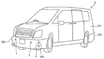
- the ultrasonic sensor 1 is mounted on a vehicle V having a box-shaped vehicle body V1. Specifically, the ultrasonic sensor 1 is attached to the front bumper V2 mounted on the front end portion of the vehicle body V1 and the rear bumper V3 mounted on the rear end portion.
- the front bumper V2 and the rear bumper V3 are formed with mounting holes V4, which are through holes for mounting the ultrasonic sensor 1.
- the ultrasonic sensor 1 mounted on the front bumper V2 and the rear bumper V3 is a so-called in-vehicle clearance sonar.
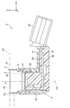
- the XYZ Cartesian coordinate system is set so that the Z axis is parallel to the directional center axis DA of the ultrasonic sensor 1 as shown in FIG.
- the direction parallel to the directional central axis DA is referred to as "axial direction".
- the upper side in FIG. 2, that is, the Z-axis positive direction side may be referred to as the "tip side” in the axial direction.
- the lower side in FIG. 2, that is, the negative direction side of the Z axis may be referred to as the "base end side” in the axial direction.
- any direction orthogonal to the axial direction may be referred to as an "in-plane direction”.
- the "in-plane direction" is the direction parallel to the XY plane in FIG.
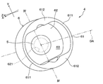
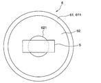
- the XYZ coordinate system corresponding to the XYZ Cartesian coordinate system of FIG. 2 is shown, and the outer shell of the recess 621 covered with the ultrasonic element 5 described later and invisible is shown by a broken line.
- the ultrasonic sensor 1 includes a sensor case 2, an elastic holding member 3, and an ultrasonic microphone 4.
- the ultrasonic microphone 4 includes an ultrasonic element 5 and an element accommodating case 6.
- the sensor case 2 is a housing of the ultrasonic sensor 1 and is configured to hold the elastic holding member 3.
- the sensor case 2 includes a case main body portion 21, a connector portion 22, and a case cylinder portion 23.
- each of these parts is integrally formed of a hard synthetic resin such as polypropylene.
- the case main body 21 is a box-shaped portion having a substantially rectangular parallelepiped outer shape, and is formed in a bottomed tubular shape in which the base end side in the axial direction opens.
- the connector portion 22 extends outward from the side wall portion of the case main body portion 21 in order to electrically connect the ultrasonic sensor 1 to an external device such as an electronic control unit.
- the case cylinder portion 23 is a substantially cylindrical portion, and projects from the case main body portion 21 to the tip end side in the axial direction.
- the case cylinder portion 23 is configured to hold the base end portion in the axial direction of the elastic holding member 3 formed in a substantially cylindrical shape centered on the directional center axis DA.
- the cylinder-shaped space inside the case cylinder portion 23 is provided so as to communicate with the substantially rectangular parallelepiped space inside the case main body portion 21.
- the space inside the case cylinder 23 and the space inside the case body 21 are collectively referred to as “the space inside the sensor case 2”.
- the circuit board 24, the wiring portion 25, and the shield portion 26 are housed in the space inside the sensor case 2.
- the circuit board 24 that controls the operation of the ultrasonic sensor 1 is housed in the case main body 21.
- the wiring portion 25 is provided so as to electrically connect the ultrasonic microphone 4 and the circuit board 24.
- the shield portion 26 is fixed to the inner surface of the sensor case 2 so as to electromagnetically shield the circuit board 24 and the wiring portion 25 by covering them.
- the damper member 27 is a disk-shaped member and has an outer diameter corresponding to the inner diameter of the elastic holding member 3. That is, the damper member 27 is fitted in the cylinder-shaped space inside the elastic holding member 3 on the proximal end side of the ultrasonic microphone 4 in the axial direction.
- the damper member 27 is provided so as to suppress vibration transmission from the ultrasonic microphone 4 to the sensor case 2.
- the damper member 27 is formed of, for example, a foamed elastic body such as foamed silicone having insulating properties and elasticity.
- the space inside the sensor case 2 is filled with a filler 28.
- the filler 28 is formed of, for example, a synthetic resin material such as silicone rubber having insulating properties and elasticity.
- the elastic holding member 3 is formed of a synthetic resin-based elastic material such as silicone rubber having insulating properties and elasticity. Synthetic resin-based elastic materials are also referred to as "viscoelastic materials" or “elastomers”.
- the elastic holding member 3 is configured to elastically support the ultrasonic microphone 4 by covering the proximal end side while exposing the distal end side in the axial direction of the ultrasonic microphone 4.
- the ultrasonic microphone 4 is composed of an ultrasonic element 5 and an element accommodating case 6, and has a function as an ultrasonic transmitter / receiver. That is, the ultrasonic microphone 4 is configured to be capable of transmitting and receiving ultrasonic waves.
- the ultrasonic microphone 4 is configured to transmit the exploration wave along the directional central axis DA based on the applied drive signal.
- the directivity central axis DA is a virtual half-line extending from the ultrasonic microphone 4 along the transmission / reception direction of ultrasonic waves, and serves as a reference for the directivity angle.
- the "directed central axis" may also be referred to as the "detection axis”.
- the ultrasonic microphone 4 is configured to receive a reflected wave from an object existing in the surroundings and generate a received signal.
- the ultrasonic element 5 is configured to convert an electric signal and ultrasonic vibration.
- the ultrasonic element 5 is, for example, a piezoelectric element, and has a thin film shape having a thickness direction in the axial direction.
- the ultrasonic element 5 is attached to the inner surface of the bottom plate portion 62 described later in the element accommodating case 6 having a bottomed tubular shape.
- the inner surface of the bottom plate portion 62 is a surface surrounded by the side plate portion 61, which will be described later.
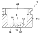
- the ultrasonic element 5 is arranged so as to cover the recess 621 formed in the bottom plate portion 62, for example, as shown in FIG. 4, and the first space 622 is provided together with the recess 621. It is configured.
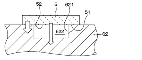
- the ultrasonic element 5 has a contact portion 51, which is a portion attached to the bottom plate portion 62, and a non-contact portion 52, which is the remaining portion, on a sticking surface which is a surface facing the bottom plate portion 62. It can be said that the non-contact portion 52 is a portion that is not attached to the bottom plate portion 62.
- the non-contact portion 52 causes two paths having different propagation velocities of vibration from the ultrasonic element 5 to the bottom plate portion 62, as shown by a white arrow in FIG. 5, for example, and the ultrasonic sensor 1 resonates a plurality of resonances. It is provided to have a frequency.
- the vibration propagation paths include a first propagation path in which the vibration propagates directly from the ultrasonic element 5 to the bottom plate portion 62, and a second propagation path in which the vibration propagates from the ultrasonic element 5 to the bottom plate portion 62 via the first space 622. There are two propagation paths. The effect of having such a configuration will be described later.
- the non-contact portion 52 preferably occupies an area of the contact portion 51 or more, in other words, occupies 50% or more of the sticking surface.
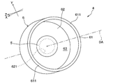
- the element accommodating case 6 has a bottomed tubular shape centered on the directional central axis DA, and has a configuration in which a second space 63 capable of accommodating the ultrasonic element 5 is provided inside.
- the element accommodating case 6 includes a side plate portion 61 and a bottom plate portion 62, which are made of the same material.
- the element accommodating case 6 is seamlessly and integrally formed of a metal such as aluminum.
- the side plate portion 61 has, for example, a cylindrical shape that surrounds the directional central axis DA and has a central axis that is substantially parallel to the directional central axis DA.
- the side plate portion 61 has a thin-walled portion 611 and a thick-walled portion 612.
- the thin-walled portion 611 has a partial cylindrical shape having a predetermined thickness in the radial direction orthogonal to the directional central axis DA.
- the "diameter direction" is a direction extending radially from the directional central axis DA. That is, the radial direction is the radial direction of the virtual circle when a virtual circle centered on the intersection of the plane and the directional center axis DA is drawn on a plane having the directional center axis DA as a normal. ..
- the radial dimension in each portion of the side plate portion 61 may be referred to as "thickness".
- the thin-walled portion 611 has a constant thickness that is thinner than the thick-walled portion 612.
- the predetermined thickness of the thin-walled portion 611 has, for example, the dimension closest to the thickness of the bottom plate portion 62 in the axial direction among the radial or axial dimensions of the side plate portion 61 and the bottom plate portion 62.
- the thin-walled portion 611 has a thickness of the bottom plate portion 62, that is, 0.3 to 2.0 times, preferably 0.5 to 1.5 times, more preferably 0.7 to 1. It is formed to be twice as thick.
- the thin portion 611 can be formed to have substantially the same thickness as the bottom plate portion 62.
- the thick portion 612 has a larger thickness, that is, a radial dimension than the thin portion 611. Specifically, in the present embodiment, the thick portion 612 has a bow shape surrounded by strings and arcs extending along the X-axis direction when viewed from a line of sight parallel to the directional central axis DA. Is formed in. Further, the thick portion 612 is arranged adjacent to the thin portion 611 in the circumferential direction surrounding the directional central axis DA. The "circumferential direction" is the circumferential direction of the above virtual circle.
- the pair of thin-walled portions 611 are arranged so as to face each other with the directional central axis DA interposed therebetween.
- the pair of thick-walled portions 612 are arranged so as to face each other with the directional center axis DA interposed therebetween. That is, in the present embodiment, the second space 63 has a rounded rectangular shape or an oval shape composed of a pair of semicircles and a pair of line segments when viewed from a line of sight parallel to the directional central axis DA. It is formed.
- the side plate portion 61 has a pair of thin-walled portions 611 provided corresponding to a semicircle and a pair of thick-walled portions 612 provided corresponding to a line segment.
- the ultrasonic microphone 4 is configured to have a directivity angle narrower in the Y-axis direction than in the X-axis direction. Since the thick portion 612 can be designed as a portion for adjusting the directivity of ultrasonic waves, it can also be referred to as a "directivity adjusting portion".
- the bottom plate portion 62 is a flat plate-shaped or thin plate-shaped portion having a thickness direction in the axial direction, and is provided so as to close one end side of the side plate portion 61 in the axial direction. Specifically, the bottom plate portion 62 is seamlessly and integrally connected to the tip portion of the side plate portion 61 in the axial direction. As shown in FIG. 3, the bottom plate portion 62 has an outer edge portion coupled to the side plate portion 61 at a fixed end when the ultrasonic element 5 is attached to the bottom plate portion 62 when transmitting or receiving ultrasonic waves by the ultrasonic element 5. It is configured to ultrasonically vibrate in the axial direction while bending.
- a recess 621 is provided on the inner side surface of the bottom plate portion 62, that is, the surface on the second space 63 side in which the ultrasonic element 5 is housed.
- the recess 621 is, for example, a syringe-shaped groove, and is formed by an arbitrary process such as a cutting process.
- the recess 621 is entirely covered with the ultrasonic element 5. That is, as shown in FIG. 3, the portion of the bottom plate portion 62 located inside the outer shell of the ultrasonic element 5 when viewed from the directional central axis DA, that is, the inner portion of the outer shell, is partly the ultrasonic element 5.
- the first space 622 is formed by separating them.
- the inner portion of the outer shell of the bottom plate portion 62 is provided with the recess 621 so that the first space 622 is provided between the bottom plate portion 62 and the ultrasonic element 5.
- the first space 622 formed by the recess 621 and the ultrasonic element 5 is filled with a medium having a vibration propagation velocity different from that of the material constituting the bottom plate portion 62, such as air or silicone.
- the first space 622 is filled with a substance different from the material constituting the bottom plate portion 62.
- the above is the basic configuration of the ultrasonic sensor 1 of the present embodiment.
- the ultrasonic element 5 vibrates ultrasonically when an electric signal is input from a wiring (not shown).
- the ultrasonic element 5 ultrasonically vibrates, the element accommodating case 6 is excited by the vibration.
- the ultrasonic microphone 4 composed of the ultrasonic element 5 and the element accommodating case 6 vibrates in a predetermined vibration mode.
- the bottom plate portion 62 is provided with a recess 621, and the ultrasonic element 5 is attached so as to cover the recess 621.
- the first space 622 formed by the recess 621 is filled with a medium whose propagation speed of vibration from the ultrasonic element 5 is different from that of the material constituting the bottom plate portion 62.
- the ultrasonic microphone 4 has a first vibration mode caused by the vibration from the ultrasonic element 5 propagating directly to the bottom plate portion 62. Further, in addition to the first vibration mode, the ultrasonic microphone 4 has a second vibration mode caused by the vibration from the ultrasonic element 5 propagating to the bottom plate portion 62 via the first space 622. Occurs. As a result, in addition to the first structural resonance frequency due to the first vibration mode, the second structural resonance frequency due to the generation of the second vibration mode is generated. It should be noted that the first structure resonance frequency and the second structure resonance frequency are in such a relationship that one does not become a higher-order resonance frequency of the other.
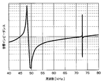
- the result shown in FIG. 6 was obtained for the acoustic impedance characteristic of the ultrasonic microphone 4 shown in FIG.
- two remarkable structural resonance frequencies are generated in the range of 40 to 80 kHz.
- One structural resonance frequency generated at about 48 kHz corresponds to the first vibration mode described above.
- the other structural resonance frequency generated at about 73 kHz is due to the generation of the second vibration mode described above.
- the other structural resonance frequency is presumed to be due to the combination of the vibration wave in the first vibration mode and the vibration in the second vibration mode.
- the recess 621 has a predetermined size and shape so as to remarkably generate a first structure resonance frequency and a second structure resonance frequency in which one does not become a higher-order resonance frequency of the other.
- the outer shape of the recess 621 is not limited to a substantially columnar shape, but may be a substantially polygonal columnar shape, a substantially elliptical columnar shape, or the like, or may have any other shape.
- one ultrasonic microphone 4 can have a plurality of structural resonance frequencies by a simple shape change of providing a recess 621 on the inner surface of the bottom plate portion 62. Further, as compared with the conventional structure in which two bottomed tubular cases of different sizes are bonded together, it is possible to obtain the effect of suppressing a decrease in durability and an increase in cost. Therefore, it is one ultrasonic sensor 1 having a configuration having a plurality of resonance frequencies while ensuring durability.
- the element accommodating case 6 may have a side plate portion 61 composed of only a thin-walled portion 611. Even with such a structure, the effect of having a plurality of resonance frequencies can be obtained by forming the recess 621 in the bottom plate portion 62 and arranging the ultrasonic element 5 on the recess 621.
- the ultrasonic microphone 4 has a structure in which the ultrasonic element 5 covers only a part of the recess 621, that is, a structure in which the first space 622 and the second space 63 communicate with each other. May be done. Even with such a structure, the ultrasonic sensor 1 has a plurality of resonance frequencies as in the above embodiment. Note that FIG. 8 shows a plan view when the ultrasonic microphone 4 is viewed from the directional central axis, and a broken line indicates a portion of the outer shell of the recess 621 that cannot be visually recognized by the ultrasonic element 5.
- the recess 621 may have a groove shape having a wedge shape in cross section as shown in FIG.
- the outer shape of the recess 621 is, for example, conical or polygonal pyramid in cross-sectional view. That is, the recess 621 may have a shape in which the ultrasonic microphone 4 has a first space 622 as a second propagation path of vibration from the ultrasonic element 5, and the shape is not limited to the above embodiment. , May be changed as appropriate.
- the depth in the first space 622 differs depending on the location due to the shape of the recess 621 described above, so that an ultrasonic sensor having three or more resonance frequencies can be obtained.
- the concave portion 621 may have a cross-sectional shape not only a wedge shape but also a shape having a plurality of points having different depths, for example, a shape having a plurality of steps, and the shape is arbitrary. .. Further, since the recess 621 has a shape having a different depth, the effect of expanding the resonance band can also be produced.
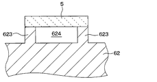
- the bottom plate portion 62 may have a shape having a frame-shaped or partial frame-shaped convex portion 623 on the inner side surface thereof instead of the concave portion 621.
- the ultrasonic element 5 is attached to the tip surface of the convex portion 623, and together with the region inside the convex portion 623 having a substantially frame shape, constitutes the third space 624.
- the inner portion of the outer shell of the bottom plate portion 62 is provided with a substantially frame-shaped convex portion 623, and the ultrasonic element 5 is attached to the tip surface of the convex portion 623 so that the ultrasonic element 5 is placed between the bottom plate portion 62 and the ultrasonic element 5. It is configured to have a third space 624.
- the convex portion 623 has a predetermined size and shape so as to remarkably generate a first structural resonance frequency and a second structural resonance frequency in which one does not become a higher-order resonance frequency of the other.
- the third space 624 may be a closed space that is not connected to the second space 63 by the ultrasonic element 5, or is a space that communicates with the second space 63 as in the second modification described above. There may be.
- the ultrasonic sensor 1 is not limited to a configuration capable of transmitting and receiving ultrasonic waves, and may have a configuration capable of only transmitting ultrasonic waves.
- the ultrasonic sensor 1 may be configured to have only a function of receiving the reflected wave of the exploration wave, which is an ultrasonic wave transmitted from another ultrasonic transmitter, by an object existing in the surroundings. That is, the ultrasonic microphone 4 may be for transmission / reception, transmission, or reception.
- the external shape of the ultrasonic microphone 4, that is, the element accommodating case 6 is not limited to a substantially cylindrical shape, and may be a substantially regular hexagonal columnar shape, a substantially regular octagonal columnar shape, or the like.
- the ultrasonic element 5 is not limited to the piezoelectric element, and for example, a so-called capacitance type element may be used.
- the plurality of components that are seamlessly and integrally formed with each other may be formed by laminating separate members from each other.
- a plurality of components formed by laminating separate members may be seamlessly and integrally formed with each other.
- the plurality of components formed of the same material may be formed of different materials.
- a plurality of components that were formed of different materials may be formed of the same material.
- the bottom plate portion 62 may have a shape in which a convex portion 623 is provided and a concave portion 621 is formed inside the convex portion 623.
Abstract
An ultrasonic sensor (1) has an ultrasonic element (5) for converting an electric signal and ultrasonic vibration, and an element housing case (6) having a bottomed tubular shape and housing the ultrasonic element thereinside. The element housing case includes a side plate portion (61) formed in a tubular shape surrounding a directional center axis (DA), and a bottom plate portion (62) closing one end side of the side plate portion in an axial direction parallel to the directional center axis. The ultrasonic element is attached to the bottom plate portion. A part of a portion of the bottom plate portion located inside the outer contour of the ultrasonic element, when viewed from the directional center axis, is separated from the ultrasonic element, thereby forming spaces (622, 624).
Description
本出願は、2019年4月23日に出願された日本特許出願番号2019-82277号に基づくもので、ここにその記載内容が参照により組み入れられる。
This application is based on Japanese Patent Application No. 2019-82277 filed on April 23, 2019, the contents of which are incorporated herein by reference.
本開示は、超音波センサに関する。
This disclosure relates to an ultrasonic sensor.
探査波として超音波を外部に送信し、その反射波を受信する超音波センサは、例えば、車両に搭載される物体検知装置等に用いられている。この種の超音波センサは、有底筒状のケースと、当該ケースの内側底部に貼り付けられた圧電素子とを有してなる。この種の超音波センサにおいては、1つの超音波センサに複数の共振周波数を持たせる構造が検討されており、例えば特許文献1に記載のものが挙げられる。特許文献1に記載の超音波センサは、大きさの異なる2つの有底筒状ケースと、圧電素子とを備え、大きい有底筒状ケースの内側底面に小さい有底筒状ケースの開口部が貼り付けられており、小さい有底筒状ケースによりなる空間を有する。この超音波センサは、小さい有底筒状ケースの外側底面に圧電素子が貼り付けられている。そして、この超音波センサは、超音波の送信時または受信時に、大小の有底筒状ケースの底面が同じ方向へ撓む場合と逆方向に撓む場合とが生じることで、複数の共振周波数を持つ構造となっている。
An ultrasonic sensor that transmits ultrasonic waves as exploration waves to the outside and receives the reflected waves is used, for example, in an object detection device mounted on a vehicle. This type of ultrasonic sensor has a bottomed tubular case and a piezoelectric element attached to the inner bottom of the case. In this type of ultrasonic sensor, a structure in which one ultrasonic sensor has a plurality of resonance frequencies has been studied, and examples thereof include those described in Patent Document 1. The ultrasonic sensor described in Patent Document 1 includes two bottomed tubular cases of different sizes and a piezoelectric element, and has a small bottomed tubular case opening on the inner bottom surface of the large bottomed tubular case. It is affixed and has a space consisting of a small bottomed tubular case. In this ultrasonic sensor, a piezoelectric element is attached to the outer bottom surface of a small bottomed tubular case. Then, in this ultrasonic sensor, when transmitting or receiving ultrasonic waves, the bottom surface of the large and small bottomed tubular case may be bent in the same direction or in the opposite direction, so that a plurality of resonance frequencies may be generated. It has a structure with.
しかしながら、この超音波センサは、大小の有底筒状ケースを接着した構造となっており、耐久性が大きく低下するおそれがあり、その製造コストも大きくなってしまう。
However, this ultrasonic sensor has a structure in which large and small bottomed tubular cases are bonded together, which may greatly reduce durability and increase the manufacturing cost.
本開示は、耐久性を確保しつつ、複数の共振周波数を有する超音波センサに関するものである。
The present disclosure relates to an ultrasonic sensor having a plurality of resonance frequencies while ensuring durability.
本開示の1つの観点によれば、超音波センサは、電気信号と超音波振動とを変換する超音波素子と、有底筒形状を有し、内側に超音波素子が収容される素子収容ケースと、を備え、素子収容ケースは、指向中心軸を囲む筒状に形成された側板部と、指向中心軸と平行な軸方向における側板部の一端側を閉塞する底板部とを有し、超音波素子は、底板部に貼り付けられており、底板部のうち指向中心軸から見て超音波素子の外郭よりも内側に位置する部分は、その一部が超音波素子と離間することで空間が形成されている。
According to one aspect of the present disclosure, the ultrasonic sensor has an ultrasonic element that converts an electric signal and ultrasonic vibration, and an element accommodating case that has a bottomed tubular shape and accommodates the ultrasonic element inside. The element accommodating case has a cylindrical side plate portion that surrounds the directional central axis and a bottom plate portion that closes one end side of the side plate portion in the axial direction parallel to the directional central axis. The sound wave element is attached to the bottom plate part, and the part of the bottom plate part located inside the outer shell of the ultrasonic element when viewed from the directional central axis is a space because a part of it is separated from the ultrasonic element. Is formed.
これにより、超音波素子からの振動が素子収容ケースの底板部に直接伝搬する場合と、当該振動が空間を介して当該底板部に伝搬する場合との2つの振動伝搬経路を備える超音波センサとなる。そのため、複数の振動モードが生じ、複数の共振周波数を有する一個の超音波センサになる。また、素子収容ケースと超音波素子との間に別部材を接着する必要がなくなり、耐久性が向上すると共に、その製造コストが抑制される。
As a result, the ultrasonic sensor has two vibration propagation paths, one is when the vibration from the ultrasonic element propagates directly to the bottom plate portion of the element housing case, and the other is when the vibration propagates to the bottom plate portion through the space. Become. Therefore, a plurality of vibration modes are generated, and one ultrasonic sensor having a plurality of resonance frequencies is obtained. Further, it is not necessary to bond another member between the element accommodating case and the ultrasonic element, the durability is improved, and the manufacturing cost thereof is suppressed.
なお、各構成要素等に付された括弧付きの参照符号は、その構成要素等と後述する実施形態に記載の具体的な構成要素等との対応関係の一例を示すものである。
Note that the reference reference numerals in parentheses attached to each component or the like indicate an example of the correspondence between the component or the like and the specific component or the like described in the embodiment described later.
以下、本開示の実施形態について図に基づいて説明する。なお、以下の各実施形態相互において、互いに同一もしくは均等である部分には、同一符号を付して説明を行う。
Hereinafter, embodiments of the present disclosure will be described with reference to the figures. In each of the following embodiments, parts that are the same or equal to each other will be described with the same reference numerals.
(実施形態)
実施形態に係る超音波センサ1について説明する。超音波センサ1は、例えば、自動車等の車両に搭載される物体検知装置に用いられると好適であるが、これに限定されず、他の用途に適用されることもできる。本実施形態では、車載用の物体検知装置に適用された例を代表例として説明する。 (Embodiment)
Theultrasonic sensor 1 according to the embodiment will be described. The ultrasonic sensor 1 is suitable for use in, for example, an object detection device mounted on a vehicle such as an automobile, but is not limited to this, and can be applied to other uses. In this embodiment, an example applied to an in-vehicle object detection device will be described as a typical example.
実施形態に係る超音波センサ1について説明する。超音波センサ1は、例えば、自動車等の車両に搭載される物体検知装置に用いられると好適であるが、これに限定されず、他の用途に適用されることもできる。本実施形態では、車載用の物体検知装置に適用された例を代表例として説明する。 (Embodiment)
The
(搭載例)
超音波センサ1の車両への搭載例について、図1を参照して簡単に説明する。超音波センサ1は、例えば図1に示すように、箱状の車体V1を備える車両Vに搭載される。具体的には、超音波センサ1は、車体V1のうち前端部に装着されたフロントバンパーV2や、後端部に装着されたリアバンパーV3に取り付けられる。 (Installation example)
An example of mounting theultrasonic sensor 1 on a vehicle will be briefly described with reference to FIG. As shown in FIG. 1, for example, the ultrasonic sensor 1 is mounted on a vehicle V having a box-shaped vehicle body V1. Specifically, the ultrasonic sensor 1 is attached to the front bumper V2 mounted on the front end portion of the vehicle body V1 and the rear bumper V3 mounted on the rear end portion.
超音波センサ1の車両への搭載例について、図1を参照して簡単に説明する。超音波センサ1は、例えば図1に示すように、箱状の車体V1を備える車両Vに搭載される。具体的には、超音波センサ1は、車体V1のうち前端部に装着されたフロントバンパーV2や、後端部に装着されたリアバンパーV3に取り付けられる。 (Installation example)
An example of mounting the
フロントバンパーV2やリアバンパーV3には、超音波センサ1を搭載するための貫通孔である装着孔V4が形成されている。フロントバンパーV2やリアバンパーV3に搭載された超音波センサ1は、いわゆる車載のクリアランスソナーとされる。
The front bumper V2 and the rear bumper V3 are formed with mounting holes V4, which are through holes for mounting the ultrasonic sensor 1. The ultrasonic sensor 1 mounted on the front bumper V2 and the rear bumper V3 is a so-called in-vehicle clearance sonar.
(構成)
次に、超音波センサ1の構成について、図2~図4を参照して説明する。 (Constitution)
Next, the configuration of theultrasonic sensor 1 will be described with reference to FIGS. 2 to 4.
次に、超音波センサ1の構成について、図2~図4を参照して説明する。 (Constitution)
Next, the configuration of the
以下、説明の便宜上、図2に示すように、Z軸が超音波センサ1の指向中心軸DAと平行となるようにXYZ直交座標系を設定する。このとき、指向中心軸DAと平行な方向を「軸方向」と称する。図2における上側、すなわち、Z軸正方向側を、軸方向における「先端側」と称することがある。同様に、図2における下側、すなわち、Z軸負方向側を、軸方向における「基端側」と称することがある。さらに、軸方向と直交する任意の方向を「面内方向」と称することがある。すなわち、「面内方向」は、図2における、XY平面と平行な方向である。また、図3では、図2のXYZ直交座標系に対応するXYZ座標系を示すと共に、後述する超音波素子5に覆われて視認できない凹部621の外郭を破線で示している。
Hereinafter, for convenience of explanation, the XYZ Cartesian coordinate system is set so that the Z axis is parallel to the directional center axis DA of the ultrasonic sensor 1 as shown in FIG. At this time, the direction parallel to the directional central axis DA is referred to as "axial direction". The upper side in FIG. 2, that is, the Z-axis positive direction side may be referred to as the "tip side" in the axial direction. Similarly, the lower side in FIG. 2, that is, the negative direction side of the Z axis may be referred to as the "base end side" in the axial direction. Further, any direction orthogonal to the axial direction may be referred to as an "in-plane direction". That is, the "in-plane direction" is the direction parallel to the XY plane in FIG. Further, in FIG. 3, the XYZ coordinate system corresponding to the XYZ Cartesian coordinate system of FIG. 2 is shown, and the outer shell of the recess 621 covered with the ultrasonic element 5 described later and invisible is shown by a broken line.
超音波センサ1は、センサケース2と、弾性保持部材3と、超音波マイクロフォン4とを備える。超音波マイクロフォン4は、超音波素子5と素子収容ケース6とを備える。以下、超音波センサ1の各構成要素について説明する。
The ultrasonic sensor 1 includes a sensor case 2, an elastic holding member 3, and an ultrasonic microphone 4. The ultrasonic microphone 4 includes an ultrasonic element 5 and an element accommodating case 6. Hereinafter, each component of the ultrasonic sensor 1 will be described.
センサケース2は、図2に示すように、超音波センサ1の筐体であると共に、弾性保持部材3を保持する構成とされている。センサケース2は、ケース本体部21と、コネクタ部22と、ケース筒部23とを有してなる。センサケース2は、これらの各部が、例えばポリプロピレン等の硬質の合成樹脂によって一体に形成されている。
As shown in FIG. 2, the sensor case 2 is a housing of the ultrasonic sensor 1 and is configured to hold the elastic holding member 3. The sensor case 2 includes a case main body portion 21, a connector portion 22, and a case cylinder portion 23. In the sensor case 2, each of these parts is integrally formed of a hard synthetic resin such as polypropylene.
ケース本体部21は、略直方体状の外形形状を有する箱状部分であって、軸方向における基端側が開口する有底筒状に形成されている。
The case main body 21 is a box-shaped portion having a substantially rectangular parallelepiped outer shape, and is formed in a bottomed tubular shape in which the base end side in the axial direction opens.
コネクタ部22は、超音波センサ1を電子制御ユニット等の外部機器と電気接続するために、ケース本体部21における側壁部から外側に向かって延設されている。
The connector portion 22 extends outward from the side wall portion of the case main body portion 21 in order to electrically connect the ultrasonic sensor 1 to an external device such as an electronic control unit.
ケース筒部23は、略円筒状の部分であって、ケース本体部21から軸方向における先端側に突設されている。ケース筒部23は、指向中心軸DAを軸中心とする略円筒形状に形成された弾性保持部材3の、軸方向における基端部を保持するように構成されている。ケース筒部23の内側のシリンダ状の空間は、ケース本体部21の内側の略直方体状の空間と連通するように設けられている。以下、ケース筒部23の内側の空間とケース本体部21の内側の空間とを総称して、「センサケース2の内側の空間」と称する。
The case cylinder portion 23 is a substantially cylindrical portion, and projects from the case main body portion 21 to the tip end side in the axial direction. The case cylinder portion 23 is configured to hold the base end portion in the axial direction of the elastic holding member 3 formed in a substantially cylindrical shape centered on the directional center axis DA. The cylinder-shaped space inside the case cylinder portion 23 is provided so as to communicate with the substantially rectangular parallelepiped space inside the case main body portion 21. Hereinafter, the space inside the case cylinder 23 and the space inside the case body 21 are collectively referred to as “the space inside the sensor case 2”.
センサケース2の内側の空間には、回路基板24と、配線部25と、シールド部26とが収容されている。超音波センサ1の動作を制御する回路基板24は、ケース本体部21に収容されている。配線部25は、超音波マイクロフォン4と回路基板24とを電気接続するように設けられている。シールド部26は、回路基板24と配線部25とを覆うことで、これらを電磁シールドするように、センサケース2の内面に固定されている。
The circuit board 24, the wiring portion 25, and the shield portion 26 are housed in the space inside the sensor case 2. The circuit board 24 that controls the operation of the ultrasonic sensor 1 is housed in the case main body 21. The wiring portion 25 is provided so as to electrically connect the ultrasonic microphone 4 and the circuit board 24. The shield portion 26 is fixed to the inner surface of the sensor case 2 so as to electromagnetically shield the circuit board 24 and the wiring portion 25 by covering them.
ダンパ部材27は、円盤状の部材であって、弾性保持部材3の内径に対応する外径を有している。すなわち、ダンパ部材27は、軸方向における超音波マイクロフォン4よりも基端側にて、弾性保持部材3の内側のシリンダ状の空間内に嵌め込まれている。ダンパ部材27は、超音波マイクロフォン4からセンサケース2への振動伝達を抑制するよう設けられている。具体的には、ダンパ部材27は、例えば、絶縁性且つ弾性を有する発泡シリコーン等の発泡弾性体によって形成されている。
The damper member 27 is a disk-shaped member and has an outer diameter corresponding to the inner diameter of the elastic holding member 3. That is, the damper member 27 is fitted in the cylinder-shaped space inside the elastic holding member 3 on the proximal end side of the ultrasonic microphone 4 in the axial direction. The damper member 27 is provided so as to suppress vibration transmission from the ultrasonic microphone 4 to the sensor case 2. Specifically, the damper member 27 is formed of, for example, a foamed elastic body such as foamed silicone having insulating properties and elasticity.
センサケース2の内側の空間には、充填材28が充填されている。充填材28は、例えば、絶縁性且つ弾性を有するシリコーンゴム等の合成樹脂材料によって形成されている。
The space inside the sensor case 2 is filled with a filler 28. The filler 28 is formed of, for example, a synthetic resin material such as silicone rubber having insulating properties and elasticity.
弾性保持部材3は、絶縁性且つ弾性を有するシリコーンゴム等の合成樹脂系弾性材料によって形成されている。合成樹脂系弾性材料は、「粘弾性材料」あるいは「エラストマ」とも称される。弾性保持部材3は、超音波マイクロフォン4の軸方向における先端側を露出させつつ基端側を覆うことで、超音波マイクロフォン4を弾性支持するように構成されている。
The elastic holding member 3 is formed of a synthetic resin-based elastic material such as silicone rubber having insulating properties and elasticity. Synthetic resin-based elastic materials are also referred to as "viscoelastic materials" or "elastomers". The elastic holding member 3 is configured to elastically support the ultrasonic microphone 4 by covering the proximal end side while exposing the distal end side in the axial direction of the ultrasonic microphone 4.
超音波マイクロフォン4は、超音波素子5と素子収容ケース6とによって構成されており、超音波送受波器としての機能を有している。すなわち、超音波マイクロフォン4は、超音波の送受信が可能な構成とされている。
The ultrasonic microphone 4 is composed of an ultrasonic element 5 and an element accommodating case 6, and has a function as an ultrasonic transmitter / receiver. That is, the ultrasonic microphone 4 is configured to be capable of transmitting and receiving ultrasonic waves.
換言すれば、超音波マイクロフォン4は、印加された駆動信号に基づいて、探査波を指向中心軸DAに沿って送信するように構成されている。指向中心軸DAは、超音波マイクロフォン4から超音波の送受信方向に沿って延びる仮想半直線であって、指向角の基準となるものである。「指向中心軸」は、「検出軸」とも称され得る。また、超音波マイクロフォン4は、周囲に存在する物体による反射波を受信して、受信信号を発生するように構成されている。
In other words, the ultrasonic microphone 4 is configured to transmit the exploration wave along the directional central axis DA based on the applied drive signal. The directivity central axis DA is a virtual half-line extending from the ultrasonic microphone 4 along the transmission / reception direction of ultrasonic waves, and serves as a reference for the directivity angle. The "directed central axis" may also be referred to as the "detection axis". Further, the ultrasonic microphone 4 is configured to receive a reflected wave from an object existing in the surroundings and generate a received signal.
超音波素子5は、電気信号と超音波振動とを変換するように構成されている。超音波素子5は、例えば圧電素子であって、軸方向に厚さ方向を有する薄膜状とされている。超音波素子5は、例えば図3に示すように、有底筒形状とされた素子収容ケース6のうち後述の底板部62の内側面に貼り付けられている。なお、底板部62の内側面とは、後述する側板部61に囲まれた面である。
The ultrasonic element 5 is configured to convert an electric signal and ultrasonic vibration. The ultrasonic element 5 is, for example, a piezoelectric element, and has a thin film shape having a thickness direction in the axial direction. As shown in FIG. 3, for example, the ultrasonic element 5 is attached to the inner surface of the bottom plate portion 62 described later in the element accommodating case 6 having a bottomed tubular shape. The inner surface of the bottom plate portion 62 is a surface surrounded by the side plate portion 61, which will be described later.
具体的には、超音波素子5は、本実施形態では、例えば図4に示すように、底板部62に形成された凹部621を覆うように配置されており、凹部621と共に第1空間622を構成している。超音波素子5は、底板部62と向き合う面である貼付面に、底板部62に貼り付けられている部分である接触部51と、残部の非接触部52とを有する。非接触部52は、底板部62に貼り付けられていない部分とも言える。
Specifically, in the present embodiment, the ultrasonic element 5 is arranged so as to cover the recess 621 formed in the bottom plate portion 62, for example, as shown in FIG. 4, and the first space 622 is provided together with the recess 621. It is configured. The ultrasonic element 5 has a contact portion 51, which is a portion attached to the bottom plate portion 62, and a non-contact portion 52, which is the remaining portion, on a sticking surface which is a surface facing the bottom plate portion 62. It can be said that the non-contact portion 52 is a portion that is not attached to the bottom plate portion 62.
この非接触部52は、例えば図5において白抜き矢印で示すように、超音波素子5から底板部62への振動の伝搬速度の異なる2つの経路を生じさせ、超音波センサ1が複数の共振周波数を持つようにするために設けられる。振動の伝搬経路は、超音波素子5から底板部62に直接振動が伝搬する第1の伝搬経路、および超音波素子5から第1空間622を介して底板部62に振動が伝搬する第2の伝搬経路の2つである。このような構成とされることによる効果については、後述する。なお、非接触部52は、上記の効果を高めるため、貼付面において、接触部51以上の面積を占めること、言い換えると貼付面の50%以上を占めることが好ましい。
The non-contact portion 52 causes two paths having different propagation velocities of vibration from the ultrasonic element 5 to the bottom plate portion 62, as shown by a white arrow in FIG. 5, for example, and the ultrasonic sensor 1 resonates a plurality of resonances. It is provided to have a frequency. The vibration propagation paths include a first propagation path in which the vibration propagates directly from the ultrasonic element 5 to the bottom plate portion 62, and a second propagation path in which the vibration propagates from the ultrasonic element 5 to the bottom plate portion 62 via the first space 622. There are two propagation paths. The effect of having such a configuration will be described later. In addition, in order to enhance the above-mentioned effect, the non-contact portion 52 preferably occupies an area of the contact portion 51 or more, in other words, occupies 50% or more of the sticking surface.
素子収容ケース6は、指向中心軸DAを軸中心とする有底筒形状であって、その内側に超音波素子5を収容可能な第2空間63を備える構成とされている。素子収容ケース6は、側板部61と底板部62とを備えており、これらが同一の材料によって構成されている。素子収容ケース6は、例えばアルミニウム等の金属によって、継ぎ目なく一体に形成されている。
The element accommodating case 6 has a bottomed tubular shape centered on the directional central axis DA, and has a configuration in which a second space 63 capable of accommodating the ultrasonic element 5 is provided inside. The element accommodating case 6 includes a side plate portion 61 and a bottom plate portion 62, which are made of the same material. The element accommodating case 6 is seamlessly and integrally formed of a metal such as aluminum.
側板部61は、例えば、指向中心軸DAを囲む筒状であって、指向中心軸DAと略平行な中心軸線を有する円筒状とされている。側板部61は、薄肉部611と、厚肉部612とを有している。
The side plate portion 61 has, for example, a cylindrical shape that surrounds the directional central axis DA and has a central axis that is substantially parallel to the directional central axis DA. The side plate portion 61 has a thin-walled portion 611 and a thick-walled portion 612.
薄肉部611は、指向中心軸DAと直交する径方向について所定厚さを有する部分円筒状とされている。「径方向」は、指向中心軸DAから放射状に延びる方向である。すなわち、径方向は、指向中心軸DAを法線とする平面上にて、当該平面と指向中心軸DAとの交点を中心とする仮想円を描いた場合の、当該仮想円の半径方向である。また、側板部61の各部における径方向寸法を「厚さ」と称することがある。換言すれば、薄肉部611は、厚肉部612よりも薄い、一定厚さを有している。
The thin-walled portion 611 has a partial cylindrical shape having a predetermined thickness in the radial direction orthogonal to the directional central axis DA. The "diameter direction" is a direction extending radially from the directional central axis DA. That is, the radial direction is the radial direction of the virtual circle when a virtual circle centered on the intersection of the plane and the directional center axis DA is drawn on a plane having the directional center axis DA as a normal. .. Further, the radial dimension in each portion of the side plate portion 61 may be referred to as "thickness". In other words, the thin-walled portion 611 has a constant thickness that is thinner than the thick-walled portion 612.
薄肉部611の所定厚さは、例えば、側板部61および底板部62の径方向または軸方向における寸法のうち、軸方向における底板部62の厚さに最も近い寸法を有している。具体的には、薄肉部611は、底板部62の厚さすなわち軸方向寸法の0.3~2.0倍、好ましくは0.5~1.5倍、より好ましくは0.7~1.2倍の厚さに形成されている。典型的には、薄肉部611は、底板部62と略同じ厚さに形成され得る。
The predetermined thickness of the thin-walled portion 611 has, for example, the dimension closest to the thickness of the bottom plate portion 62 in the axial direction among the radial or axial dimensions of the side plate portion 61 and the bottom plate portion 62. Specifically, the thin-walled portion 611 has a thickness of the bottom plate portion 62, that is, 0.3 to 2.0 times, preferably 0.5 to 1.5 times, more preferably 0.7 to 1. It is formed to be twice as thick. Typically, the thin portion 611 can be formed to have substantially the same thickness as the bottom plate portion 62.
厚肉部612は、薄肉部611よりも大きな厚さすなわち径方向寸法を有している。具体的には、本実施形態においては、厚肉部612は、指向中心軸DAと平行な視線で見た場合に、X軸方向に沿って延設された弦と円弧とで囲まれた弓形に形成されている。また、厚肉部612は、指向中心軸DAを囲む周方向について薄肉部611に隣接配置されている。「周方向」は、上記の仮想円の円周方向である。
The thick portion 612 has a larger thickness, that is, a radial dimension than the thin portion 611. Specifically, in the present embodiment, the thick portion 612 has a bow shape surrounded by strings and arcs extending along the X-axis direction when viewed from a line of sight parallel to the directional central axis DA. Is formed in. Further, the thick portion 612 is arranged adjacent to the thin portion 611 in the circumferential direction surrounding the directional central axis DA. The "circumferential direction" is the circumferential direction of the above virtual circle.
本実施形態では、一対の薄肉部611は、指向中心軸DAを挟んで対向配置されている。同様に、一対の厚肉部612は、指向中心軸DAを挟んで対向配置されている。すなわち、本実施形態では、第2空間63は、指向中心軸DAと平行な視線で見た場合に、一対の半円と一対の線分とで構成される角丸長方形状あるいは長円状に形成されている。また、側板部61は、半円に対応して設けられた一対の薄肉部611と、線分に対応して設けられた一対の厚肉部612とを有している。これにより、超音波マイクロフォン4は、Y軸方向にてX軸方向よりも狭い指向角を有するように構成されている。なお、厚肉部612は、超音波の指向性を調整する部位として設計され得るため、「指向性調整部」とも称され得る。
In the present embodiment, the pair of thin-walled portions 611 are arranged so as to face each other with the directional central axis DA interposed therebetween. Similarly, the pair of thick-walled portions 612 are arranged so as to face each other with the directional center axis DA interposed therebetween. That is, in the present embodiment, the second space 63 has a rounded rectangular shape or an oval shape composed of a pair of semicircles and a pair of line segments when viewed from a line of sight parallel to the directional central axis DA. It is formed. Further, the side plate portion 61 has a pair of thin-walled portions 611 provided corresponding to a semicircle and a pair of thick-walled portions 612 provided corresponding to a line segment. As a result, the ultrasonic microphone 4 is configured to have a directivity angle narrower in the Y-axis direction than in the X-axis direction. Since the thick portion 612 can be designed as a portion for adjusting the directivity of ultrasonic waves, it can also be referred to as a "directivity adjusting portion".
底板部62は、軸方向に厚さ方向を有する平板状あるいは薄板状の部分であって、軸方向における側板部61の一端側を閉塞するように設けられている。具体的には、底板部62は、側板部61の軸方向における先端部と継ぎ目なく一体的に結合されている。底板部62は、図3に示すように、超音波素子5が貼り付けられることで、超音波素子5による超音波の送信または受信の際に、側板部61と結合された外縁部を固定端として撓みながら軸方向に超音波振動する構成とされている。底板部62のうち内側面、すなわち超音波素子5が収容される第2空間63側の面には、凹部621が設けられている。
The bottom plate portion 62 is a flat plate-shaped or thin plate-shaped portion having a thickness direction in the axial direction, and is provided so as to close one end side of the side plate portion 61 in the axial direction. Specifically, the bottom plate portion 62 is seamlessly and integrally connected to the tip portion of the side plate portion 61 in the axial direction. As shown in FIG. 3, the bottom plate portion 62 has an outer edge portion coupled to the side plate portion 61 at a fixed end when the ultrasonic element 5 is attached to the bottom plate portion 62 when transmitting or receiving ultrasonic waves by the ultrasonic element 5. It is configured to ultrasonically vibrate in the axial direction while bending. A recess 621 is provided on the inner side surface of the bottom plate portion 62, that is, the surface on the second space 63 side in which the ultrasonic element 5 is housed.
凹部621は、例えば、シリンジ状の溝とされており、切削工程等の任意の工程により形成される。凹部621は、本実施形態では、その全部が超音波素子5により覆われている。つまり、図3に示すように、底板部62のうち指向中心軸DAから見て超音波素子5の外郭よりも内側に位置する部分、すなわち外郭内側部は、その一部が超音波素子5と離間することで第1空間622が形成されている。本実施形態では、底板部62のうち外郭内側部は、凹部621を備えることにより、超音波素子5との間に第1空間622を有する構成とされる。
The recess 621 is, for example, a syringe-shaped groove, and is formed by an arbitrary process such as a cutting process. In the present embodiment, the recess 621 is entirely covered with the ultrasonic element 5. That is, as shown in FIG. 3, the portion of the bottom plate portion 62 located inside the outer shell of the ultrasonic element 5 when viewed from the directional central axis DA, that is, the inner portion of the outer shell, is partly the ultrasonic element 5. The first space 622 is formed by separating them. In the present embodiment, the inner portion of the outer shell of the bottom plate portion 62 is provided with the recess 621 so that the first space 622 is provided between the bottom plate portion 62 and the ultrasonic element 5.
なお、凹部621と超音波素子5とにより形成される第1空間622は、例えば空気やシリコーン等の、底板部62を構成する材料とは異なる振動伝搬速度となる媒質が充填されている。言い換えると、第1空間622は、底板部62を構成する材料とは異なる物質が充填されている。
The first space 622 formed by the recess 621 and the ultrasonic element 5 is filled with a medium having a vibration propagation velocity different from that of the material constituting the bottom plate portion 62, such as air or silicone. In other words, the first space 622 is filled with a substance different from the material constituting the bottom plate portion 62.
以上が、本実施形態の超音波センサ1の基本的な構成である。
The above is the basic configuration of the ultrasonic sensor 1 of the present embodiment.
(効果)
次に、本実施形態の超音波センサ1による効果について、図5、図6を参照して説明する。 (effect)
Next, the effect of theultrasonic sensor 1 of the present embodiment will be described with reference to FIGS. 5 and 6.
次に、本実施形態の超音波センサ1による効果について、図5、図6を参照して説明する。 (effect)
Next, the effect of the
上記構成の超音波センサ1では、超音波素子5は、図示しない配線から電気信号が入力されることで超音波振動する。超音波素子5が超音波振動すると、その振動により、素子収容ケース6が励振される。これにより、超音波素子5と素子収容ケース6とによって構成される超音波マイクロフォン4は、所定の振動モードで振動する。
In the ultrasonic sensor 1 having the above configuration, the ultrasonic element 5 vibrates ultrasonically when an electric signal is input from a wiring (not shown). When the ultrasonic element 5 ultrasonically vibrates, the element accommodating case 6 is excited by the vibration. As a result, the ultrasonic microphone 4 composed of the ultrasonic element 5 and the element accommodating case 6 vibrates in a predetermined vibration mode.
ここで、上記構成では、底板部62は、凹部621が設けられると共に、超音波素子5が凹部621を覆うように貼り付けられている。そして、凹部621によりなる第1空間622は、超音波素子5からの振動の伝搬速度が、底板部62を構成する材料とは異なる媒質により充填されている。
Here, in the above configuration, the bottom plate portion 62 is provided with a recess 621, and the ultrasonic element 5 is attached so as to cover the recess 621. The first space 622 formed by the recess 621 is filled with a medium whose propagation speed of vibration from the ultrasonic element 5 is different from that of the material constituting the bottom plate portion 62.
このため、超音波マイクロフォン4には、図5に示すように、超音波素子5からの振動が底板部62に直接伝搬することに起因する第1の振動モードが生じる。また、超音波マイクロフォン4には、この第1の振動モードに加えて、超音波素子5からの振動が第1空間622を介して底板部62に伝搬することに起因する第2の振動モードが生じる。これにより、第1の振動モードによる第一構造共振周波数の他に、第2の振動モードの発生に起因する第二構造共振周波数が発生する。なお、第一構造共振周波数と第二構造共振周波数とは、一方が他方の高次共振周波数とはならないような関係とされる。
Therefore, as shown in FIG. 5, the ultrasonic microphone 4 has a first vibration mode caused by the vibration from the ultrasonic element 5 propagating directly to the bottom plate portion 62. Further, in addition to the first vibration mode, the ultrasonic microphone 4 has a second vibration mode caused by the vibration from the ultrasonic element 5 propagating to the bottom plate portion 62 via the first space 622. Occurs. As a result, in addition to the first structural resonance frequency due to the first vibration mode, the second structural resonance frequency due to the generation of the second vibration mode is generated. It should be noted that the first structure resonance frequency and the second structure resonance frequency are in such a relationship that one does not become a higher-order resonance frequency of the other.
上記の振動状態を計算機シミュレーションした結果、図3に示す超音波マイクロフォン4の音響インピーダンス特性について、図6に示す結果が得られた。超音波マイクロフォン4では、40~80kHzの範囲内において、二個の顕著な構造共振周波数が発生している。約48kHzにて発生している一方の構造共振周波数は、上記の第1の振動モードに対応する。約73kHzにて発生している他方の構造共振周波数は、上記の第2の振動モードの発生に起因する。具体的には、他方の構造共振周波数は、第1の振動モードによる振動波と、第2の振動モードによる振動とが合成されたものによると推定される。
As a result of computer simulation of the above vibration state, the result shown in FIG. 6 was obtained for the acoustic impedance characteristic of the ultrasonic microphone 4 shown in FIG. In the ultrasonic microphone 4, two remarkable structural resonance frequencies are generated in the range of 40 to 80 kHz. One structural resonance frequency generated at about 48 kHz corresponds to the first vibration mode described above. The other structural resonance frequency generated at about 73 kHz is due to the generation of the second vibration mode described above. Specifically, the other structural resonance frequency is presumed to be due to the combination of the vibration wave in the first vibration mode and the vibration in the second vibration mode.
なお、凹部621は、上記したように、一方が他方の高次共振周波数とはならない第一構造共振周波数および第二構造共振周波数を顕著に発生させるような、所定の寸法や形状とされる。例えば、凹部621は、その外郭形状が略円柱状に限られず、略多角柱状や略楕円柱状等にもされ得るし、その他の形状にもされ得る。
As described above, the recess 621 has a predetermined size and shape so as to remarkably generate a first structure resonance frequency and a second structure resonance frequency in which one does not become a higher-order resonance frequency of the other. For example, the outer shape of the recess 621 is not limited to a substantially columnar shape, but may be a substantially polygonal columnar shape, a substantially elliptical columnar shape, or the like, or may have any other shape.
本実施形態によれば、底板部62の内側面に凹部621を設けるという、簡単な形状変更により一個の超音波マイクロフォン4に複数の構造共振周波数を持たせることができる。また、大小の異なる2つの有底筒状ケースを貼り合わせるような従来構造に比べて、耐久性の低下やコストの増大が抑制されるとの効果も得られる。そのため、耐久性を確保しつつも、複数の共振周波数を有する構成とされた一個の超音波センサ1となる。
According to this embodiment, one ultrasonic microphone 4 can have a plurality of structural resonance frequencies by a simple shape change of providing a recess 621 on the inner surface of the bottom plate portion 62. Further, as compared with the conventional structure in which two bottomed tubular cases of different sizes are bonded together, it is possible to obtain the effect of suppressing a decrease in durability and an increase in cost. Therefore, it is one ultrasonic sensor 1 having a configuration having a plurality of resonance frequencies while ensuring durability.
(第1の変形例)
超音波センサ1において、素子収容ケース6は、図7に示すように、側板部61が薄肉部611のみで構成されてもよい。このような構造であっても、底板部62に凹部621が形成され、その上に超音波素子5が配置されることで、複数の共振周波数を有するとの効果が得られる。 (First modification)
In theultrasonic sensor 1, as shown in FIG. 7, the element accommodating case 6 may have a side plate portion 61 composed of only a thin-walled portion 611. Even with such a structure, the effect of having a plurality of resonance frequencies can be obtained by forming the recess 621 in the bottom plate portion 62 and arranging the ultrasonic element 5 on the recess 621.
超音波センサ1において、素子収容ケース6は、図7に示すように、側板部61が薄肉部611のみで構成されてもよい。このような構造であっても、底板部62に凹部621が形成され、その上に超音波素子5が配置されることで、複数の共振周波数を有するとの効果が得られる。 (First modification)
In the
(第2の変形例)
超音波センサ1において、超音波マイクロフォン4は、図8に示すように、超音波素子5が凹部621の一部のみを覆う構造、すなわち第1空間622と第2空間63とが連通する構造とされてもよい。このような構造であっても、上記実施形態と同様に、複数の共振周波数を有する超音波センサ1となる。なお、図8では、指向中心軸から超音波マイクロフォン4を見たときの平面図を示すと共に、凹部621の外郭のうち超音波素子5により視認できない部分を破線で示している。 (Second modification)
In theultrasonic sensor 1, as shown in FIG. 8, the ultrasonic microphone 4 has a structure in which the ultrasonic element 5 covers only a part of the recess 621, that is, a structure in which the first space 622 and the second space 63 communicate with each other. May be done. Even with such a structure, the ultrasonic sensor 1 has a plurality of resonance frequencies as in the above embodiment. Note that FIG. 8 shows a plan view when the ultrasonic microphone 4 is viewed from the directional central axis, and a broken line indicates a portion of the outer shell of the recess 621 that cannot be visually recognized by the ultrasonic element 5.
超音波センサ1において、超音波マイクロフォン4は、図8に示すように、超音波素子5が凹部621の一部のみを覆う構造、すなわち第1空間622と第2空間63とが連通する構造とされてもよい。このような構造であっても、上記実施形態と同様に、複数の共振周波数を有する超音波センサ1となる。なお、図8では、指向中心軸から超音波マイクロフォン4を見たときの平面図を示すと共に、凹部621の外郭のうち超音波素子5により視認できない部分を破線で示している。 (Second modification)
In the
(第3の変形例)
超音波センサ1において、凹部621は、図9に示すように、断面形状がくさび形状とされた溝状であってもよい。この場合、凹部621は、断面視にて、その外郭形状が例えば円錐状や多角錐状などとされる。つまり、凹部621は、超音波マイクロフォン4に、超音波素子5からの振動の第2の伝搬経路となる第1空間622が生じる形状であればよく、その形状については上記の実施形態に限られず、適宜変更されてもよい。 (Third variant)
In theultrasonic sensor 1, the recess 621 may have a groove shape having a wedge shape in cross section as shown in FIG. In this case, the outer shape of the recess 621 is, for example, conical or polygonal pyramid in cross-sectional view. That is, the recess 621 may have a shape in which the ultrasonic microphone 4 has a first space 622 as a second propagation path of vibration from the ultrasonic element 5, and the shape is not limited to the above embodiment. , May be changed as appropriate.
超音波センサ1において、凹部621は、図9に示すように、断面形状がくさび形状とされた溝状であってもよい。この場合、凹部621は、断面視にて、その外郭形状が例えば円錐状や多角錐状などとされる。つまり、凹部621は、超音波マイクロフォン4に、超音波素子5からの振動の第2の伝搬経路となる第1空間622が生じる形状であればよく、その形状については上記の実施形態に限られず、適宜変更されてもよい。 (Third variant)
In the
なお、底板部62の厚み方向における底板部62と超音波素子5との距離を「深さ」として、上記の実施形態では、第1空間622における深さが一定である例について説明した。これに対して、本変形例では、上記した凹部621の形状により、第1空間622における深さが場所により異なるため、3つ以上の共振周波数を有する超音波センサとすることも可能となる。なお、この場合、凹部621は、断面形状がくさび形状だけでなく、例えば複数の段差を有する形状といった、深さが異なる複数の箇所を有する形状とされてもよく、その形状については任意である。また、凹部621は、深さが異なる形状とされることで、共振の帯域を拡大する効果も生じさせ得る。
In the above embodiment, an example in which the depth in the first space 622 is constant has been described with the distance between the bottom plate portion 62 and the ultrasonic element 5 in the thickness direction of the bottom plate portion 62 as the “depth”. On the other hand, in this modification, the depth in the first space 622 differs depending on the location due to the shape of the recess 621 described above, so that an ultrasonic sensor having three or more resonance frequencies can be obtained. In this case, the concave portion 621 may have a cross-sectional shape not only a wedge shape but also a shape having a plurality of points having different depths, for example, a shape having a plurality of steps, and the shape is arbitrary. .. Further, since the recess 621 has a shape having a different depth, the effect of expanding the resonance band can also be produced.
(第4の変形例)
超音波センサ1において、底板部62は、図10に示すように、その内側面において凹部621に代わって、枠体状または部分枠体状の凸部623を有する形状とされてもよい。この場合、超音波素子5は、凸部623の先端面に貼り付けられ、略枠体状の凸部623の内側の領域と併せて、第3空間624を構成する。言い換えると、底板部62のうち外郭内側部は、略枠体状の凸部623を備え、凸部623の先端面に超音波素子5が貼り付けられることで、超音波素子5との間に第3空間624を有する構成とされる。 (Fourth modification)
In theultrasonic sensor 1, as shown in FIG. 10, the bottom plate portion 62 may have a shape having a frame-shaped or partial frame-shaped convex portion 623 on the inner side surface thereof instead of the concave portion 621. In this case, the ultrasonic element 5 is attached to the tip surface of the convex portion 623, and together with the region inside the convex portion 623 having a substantially frame shape, constitutes the third space 624. In other words, the inner portion of the outer shell of the bottom plate portion 62 is provided with a substantially frame-shaped convex portion 623, and the ultrasonic element 5 is attached to the tip surface of the convex portion 623 so that the ultrasonic element 5 is placed between the bottom plate portion 62 and the ultrasonic element 5. It is configured to have a third space 624.
超音波センサ1において、底板部62は、図10に示すように、その内側面において凹部621に代わって、枠体状または部分枠体状の凸部623を有する形状とされてもよい。この場合、超音波素子5は、凸部623の先端面に貼り付けられ、略枠体状の凸部623の内側の領域と併せて、第3空間624を構成する。言い換えると、底板部62のうち外郭内側部は、略枠体状の凸部623を備え、凸部623の先端面に超音波素子5が貼り付けられることで、超音波素子5との間に第3空間624を有する構成とされる。 (Fourth modification)
In the
これにより、超音波素子5からの振動が凸部623を介して底板部62に伝搬することによる振動モードと、超音波素子5からの振動が第3空間624を介して底板部62に伝搬することによる追加の振動モードとが生じる超音波マイクロフォン4となる。そのため、この構造によっても、複数の共振周波数を有する超音波センサ1が得られる。
As a result, the vibration mode in which the vibration from the ultrasonic element 5 propagates to the bottom plate portion 62 via the convex portion 623 and the vibration from the ultrasonic element 5 propagates to the bottom plate portion 62 via the third space 624. This results in an ultrasonic microphone 4 with an additional vibration mode. Therefore, even with this structure, an ultrasonic sensor 1 having a plurality of resonance frequencies can be obtained.
なお、凸部623は、凹部621と同様に、一方が他方の高次共振周波数とはならない第一構造共振周波数および第二構造共振周波数を顕著に発生させるような、所定の寸法や形状とされる。また、第3空間624は、超音波素子5により第2空間63と繋がっていない閉鎖空間であってもよいし、上記の第2の変形例と同様に、第2空間63と連通する空間であってもよい。
Similar to the concave portion 621, the convex portion 623 has a predetermined size and shape so as to remarkably generate a first structural resonance frequency and a second structural resonance frequency in which one does not become a higher-order resonance frequency of the other. Resonant. Further, the third space 624 may be a closed space that is not connected to the second space 63 by the ultrasonic element 5, or is a space that communicates with the second space 63 as in the second modification described above. There may be.
(他の実施形態)
本開示は、実施例に準拠して記述されたが、本開示は当該実施例や構造に限定されるものではないと理解される。本開示は、様々な変形例や均等範囲内の変形をも包含する。加えて、様々な組み合わせや形態、さらには、それらの一要素のみ、それ以上、あるいはそれ以下、を含む他の組み合わせや形態をも、本開示の範疇や思想範囲に入るものである。 (Other embodiments)
Although the present disclosure has been described in accordance with the examples, it is understood that the present disclosure is not limited to the examples and structures. The present disclosure also includes various modifications and modifications within an equal range. In addition, various combinations and forms, as well as other combinations and forms including only one element thereof, more or less, are also within the scope of the present disclosure.
(1)例えば、超音波センサ1は、超音波を送受信可能な構成に限定されず、超音波の発信のみが可能な構成であってもよい。あるいは、超音波センサ1は、他の超音波発信器から発信された超音波である探査波の、周囲に存在する物体による反射波を受信する機能のみを有する構成であってもよい。つまり、超音波マイクロフォン4は、送受信用であってもよいし、送信用であってもよいし、受信用であってもよい。
(1) For example, the ultrasonic sensor 1 is not limited to a configuration capable of transmitting and receiving ultrasonic waves, and may have a configuration capable of only transmitting ultrasonic waves. Alternatively, the ultrasonic sensor 1 may be configured to have only a function of receiving the reflected wave of the exploration wave, which is an ultrasonic wave transmitted from another ultrasonic transmitter, by an object existing in the surroundings. That is, the ultrasonic microphone 4 may be for transmission / reception, transmission, or reception.
(2)超音波マイクロフォン4すなわち素子収容ケース6の外形形状は、略円柱状に限定されず、略正六角柱状、略正八角柱状、等であってもよい。
(2) The external shape of the ultrasonic microphone 4, that is, the element accommodating case 6 is not limited to a substantially cylindrical shape, and may be a substantially regular hexagonal columnar shape, a substantially regular octagonal columnar shape, or the like.
(3)超音波素子5は、圧電素子に限定されず、例えば、いわゆる静電容量型素子が用いられてもよい。
(3) The ultrasonic element 5 is not limited to the piezoelectric element, and for example, a so-called capacitance type element may be used.
(4)上記の説明において、互いに継ぎ目無く一体に形成されていた複数の構成要素は、互いに別体の部材を貼り合わせることによって形成されてもよい。同様に、互いに別体の部材を貼り合わせることによって形成されていた複数の構成要素は、互いに継ぎ目無く一体に形成されてもよい。
(4) In the above description, the plurality of components that are seamlessly and integrally formed with each other may be formed by laminating separate members from each other. Similarly, a plurality of components formed by laminating separate members may be seamlessly and integrally formed with each other.
(5)上記の説明において、互いに同一の材料によって形成されていた複数の構成要素は、互いに異なる材料によって形成されてもよい。同様に、互いに異なる材料によって形成されていた複数の構成要素は、互いに同一の材料によって形成されてもよい。
(5) In the above description, the plurality of components formed of the same material may be formed of different materials. Similarly, a plurality of components that were formed of different materials may be formed of the same material.
(6)上記の実施形態およびその変形例については、互いに組み合わせられてもよい。例えば、底板部62は、凸部623を備えると共に、その内側に凹部621が形成された形状とされてもよい。
(6) The above embodiments and modifications thereof may be combined with each other. For example, the bottom plate portion 62 may have a shape in which a convex portion 623 is provided and a concave portion 621 is formed inside the convex portion 623.
Claims (9)
- 超音波センサ(1)であって、
電気信号と超音波振動とを変換する超音波素子(5)と、
有底筒形状を有し、内側に前記超音波素子が収容される素子収容ケース(6)と、を備え、
前記素子収容ケースは、指向中心軸(DA)を囲む筒状に形成された側板部(61)と、前記指向中心軸と平行な軸方向における前記側板部の一端側を閉塞する底板部(62)とを有し、
前記超音波素子は、前記底板部に貼り付けられており、
前記底板部のうち前記指向中心軸から見て前記超音波素子の外郭よりも内側に位置する部分は、その一部が前記超音波素子と離間することで空間(622、624)が形成されている、超音波センサ。 Ultrasonic sensor (1)
An ultrasonic element (5) that converts an electric signal and ultrasonic vibration,
It has an element accommodating case (6) having a bottomed tubular shape and accommodating the ultrasonic element inside.
The element accommodating case includes a side plate portion (61) formed in a tubular shape surrounding the directional central axis (DA) and a bottom plate portion (62) that closes one end side of the side plate portion in an axial direction parallel to the directional central axis. ) And
The ultrasonic element is attached to the bottom plate portion, and the ultrasonic element is attached to the bottom plate portion.
A space (622, 624) is formed in the portion of the bottom plate portion located inside the outer shell of the ultrasonic element when viewed from the directional central axis by separating a part of the bottom plate portion from the ultrasonic element. There is an ultrasonic sensor. - 前記超音波素子のうち前記底板部と向き合う面であって、前記底板部に貼り付けられた部分を接触部(51)とし、残部を非接触部(52)として、
前記非接触部の面積は、前記接触部の面積以上である、請求項1に記載の超音波センサ。 The surface of the ultrasonic element facing the bottom plate portion, where the portion attached to the bottom plate portion is a contact portion (51) and the rest is a non-contact portion (52).
The ultrasonic sensor according to claim 1, wherein the area of the non-contact portion is equal to or larger than the area of the contact portion. - 前記側板部は、前記指向中心軸と直交する径方向について所定厚さを有する円筒状または部分円筒状の薄肉部(611)と、前記指向中心軸を囲む周方向における前記薄肉部の一部に設けられていて前記所定厚さよりも大きな径方向寸法を有する厚肉部(612)とを有する、請求項1または2に記載の超音波センサ。 The side plate portion is formed on a cylindrical or partially cylindrical thin-walled portion (611) having a predetermined thickness in the radial direction orthogonal to the directional central axis and a part of the thin-walled portion in the circumferential direction surrounding the directional central axis. The ultrasonic sensor according to claim 1 or 2, further comprising a thick portion (612) provided and having a radial dimension larger than the predetermined thickness.
- 前記超音波素子は、前記空間の一部または全部を覆っている、請求項1ないし3のいずれか1つに記載の超音波センサ。 The ultrasonic sensor according to any one of claims 1 to 3, wherein the ultrasonic element covers a part or the whole of the space.
- 前記空間には、前記底板部を構成する材料とは異なる物質が充填されている、請求項1ないし4のいずれか1つに記載の超音波センサ。 The ultrasonic sensor according to any one of claims 1 to 4, wherein the space is filled with a substance different from the material constituting the bottom plate portion.
- 前記底板部は、凹部(621)を備え、
前記空間(622)は、前記超音波素子と前記凹部とにより形成される、請求項1ないし5のいずれか1つに記載の超音波センサ。 The bottom plate portion includes a recess (621).
The ultrasonic sensor according to any one of claims 1 to 5, wherein the space (622) is formed by the ultrasonic element and the recess. - 前記底板部は、枠体状または部分枠体状の凸部(623)を備え、
前記超音波素子は、前記凸部の先端面に貼り付けられており、
前記空間(624)は、前記超音波素子と前記凸部の内側の領域とにより形成される、請求項1ないし5のいずれか1つに記載の超音波センサ。 The bottom plate portion includes a frame-shaped or partial frame-shaped convex portion (623).
The ultrasonic element is attached to the tip surface of the convex portion.
The ultrasonic sensor according to any one of claims 1 to 5, wherein the space (624) is formed by the ultrasonic element and a region inside the convex portion. - 前記底板部の厚み方向における前記超音波素子と前記底板部との距離を深さとして、
前記空間における前記深さは、一定である、請求項1ないし7のいずれか1つに記載の超音波センサ。 The distance between the ultrasonic element and the bottom plate in the thickness direction of the bottom plate is defined as the depth.
The ultrasonic sensor according to any one of claims 1 to 7, wherein the depth in the space is constant. - 前記底板部の厚み方向における前記超音波素子と前記底板部との距離を深さとして、
前記空間における前記深さは、場所により異なる、請求項1ないし7のいずれか1つに記載の超音波センサ。 The distance between the ultrasonic element and the bottom plate in the thickness direction of the bottom plate is defined as the depth.
The ultrasonic sensor according to any one of claims 1 to 7, wherein the depth in the space varies depending on the location.
Priority Applications (3)
| Application Number | Priority Date | Filing Date | Title |
|---|---|---|---|
| CN202080030384.5A CN113728658A (en) | 2019-04-23 | 2020-04-10 | Ultrasonic sensor |
| DE112020002082.7T DE112020002082T5 (en) | 2019-04-23 | 2020-04-10 | Ultrasonic sensor |
| US17/507,686 US20220043147A1 (en) | 2019-04-23 | 2021-10-21 | Ultrasonic sensor |
Applications Claiming Priority (2)
| Application Number | Priority Date | Filing Date | Title |
|---|---|---|---|
| JP2019082277A JP7192640B2 (en) | 2019-04-23 | 2019-04-23 | ultrasonic sensor |
| JP2019-082277 | 2019-04-23 |
Related Child Applications (1)
| Application Number | Title | Priority Date | Filing Date |
|---|---|---|---|
| US17/507,686 Continuation US20220043147A1 (en) | 2019-04-23 | 2021-10-21 | Ultrasonic sensor |
Publications (1)
| Publication Number | Publication Date |
|---|---|
| WO2020218038A1 true WO2020218038A1 (en) | 2020-10-29 |
Family
ID=72942508
Family Applications (1)
| Application Number | Title | Priority Date | Filing Date |
|---|---|---|---|
| PCT/JP2020/016205 WO2020218038A1 (en) | 2019-04-23 | 2020-04-10 | Ultrasonic sensor |
Country Status (5)
| Country | Link |
|---|---|
| US (1) | US20220043147A1 (en) |
| JP (1) | JP7192640B2 (en) |
| CN (1) | CN113728658A (en) |
| DE (1) | DE112020002082T5 (en) |
| WO (1) | WO2020218038A1 (en) |
Families Citing this family (1)
| Publication number | Priority date | Publication date | Assignee | Title |
|---|---|---|---|---|
| JP7184105B2 (en) * | 2021-02-08 | 2022-12-06 | Tdk株式会社 | ultrasonic transducer |
Citations (1)
| Publication number | Priority date | Publication date | Assignee | Title |
|---|---|---|---|---|
| JP2009055458A (en) * | 2007-08-28 | 2009-03-12 | Nippon Ceramic Co Ltd | Ultrasonic wave transmitting/receiving apparatus |
Family Cites Families (18)
| Publication number | Priority date | Publication date | Assignee | Title |
|---|---|---|---|---|
| JP4513596B2 (en) * | 2004-08-25 | 2010-07-28 | 株式会社デンソー | Ultrasonic sensor |
| JP4438667B2 (en) * | 2005-03-29 | 2010-03-24 | 株式会社デンソー | Ultrasonic sensor and ultrasonic transducer |
| WO2007069609A1 (en) * | 2005-12-14 | 2007-06-21 | Murata Manufacturing Co., Ltd. | Ultrasonic transducer |
| GB0605576D0 (en) * | 2006-03-20 | 2006-04-26 | Oligon Ltd | MEMS device |
| JP4442632B2 (en) * | 2007-04-24 | 2010-03-31 | パナソニック電工株式会社 | Ultrasonic sensor |
| DE202007007135U1 (en) | 2007-05-18 | 2007-08-16 | Seco Sensor Consult Gmbh | Ultrasonic transducer for sending and receiving ultrasonic signal in e.g. air, has piezoelectric transducer unit e.g. piezoceramic, radially coupled to pot base in form-fit and force-fit manner, and housing made of aluminum oxide |
| CN102227919B (en) * | 2008-12-04 | 2014-04-09 | 株式会社村田制作所 | Ultrasonic wave transmitter/receiver |
| JP2010278594A (en) | 2009-05-27 | 2010-12-09 | Nippon Ceramic Co Ltd | Ultrasonic transmitter-receiver |
| JP5537321B2 (en) | 2010-07-28 | 2014-07-02 | 日本セラミック株式会社 | Ultrasonic transceiver |
| JP5339093B2 (en) * | 2010-09-08 | 2013-11-13 | 株式会社村田製作所 | Ultrasonic transducer |
| CN103180755B (en) * | 2010-12-10 | 2014-10-08 | 三菱电机株式会社 | Air-coupled ultrasonic sensor |
| JP5390545B2 (en) * | 2011-01-24 | 2014-01-15 | 株式会社タムラ製作所 | Piezoelectric sensor |
| JP5984082B2 (en) * | 2011-12-28 | 2016-09-06 | パナソニックIpマネジメント株式会社 | Ultrasonic sensor |
| DE102012201884A1 (en) | 2012-02-09 | 2013-08-14 | Robert Bosch Gmbh | transducer |
| CA2929723C (en) * | 2013-12-12 | 2020-09-15 | Qualcomm Incorporated | Micromechanical ultrasonic transducers and display |
| JP6249168B2 (en) * | 2014-04-08 | 2017-12-20 | 株式会社デンソー | Ultrasonic sensor for vehicle and distance detector for vehicle equipped with the same |
| CN106659463B (en) * | 2014-05-14 | 2019-11-19 | 皇家飞利浦有限公司 | Acoustic lens and ultrasound transducer probe |
| JP6493486B1 (en) | 2017-10-30 | 2019-04-03 | ダイキン工業株式会社 | Air conditioner |
-
2019
- 2019-04-23 JP JP2019082277A patent/JP7192640B2/en active Active
-
2020
- 2020-04-10 CN CN202080030384.5A patent/CN113728658A/en active Pending
- 2020-04-10 DE DE112020002082.7T patent/DE112020002082T5/en active Pending
- 2020-04-10 WO PCT/JP2020/016205 patent/WO2020218038A1/en active Application Filing
-
2021
- 2021-10-21 US US17/507,686 patent/US20220043147A1/en active Pending
Patent Citations (1)
| Publication number | Priority date | Publication date | Assignee | Title |
|---|---|---|---|---|
| JP2009055458A (en) * | 2007-08-28 | 2009-03-12 | Nippon Ceramic Co Ltd | Ultrasonic wave transmitting/receiving apparatus |
Also Published As
| Publication number | Publication date |
|---|---|
| JP7192640B2 (en) | 2022-12-20 |
| US20220043147A1 (en) | 2022-02-10 |
| CN113728658A (en) | 2021-11-30 |
| DE112020002082T5 (en) | 2022-01-05 |
| JP2020182038A (en) | 2020-11-05 |
Similar Documents
| Publication | Publication Date | Title |
|---|---|---|
| EP1962552B1 (en) | Ultrasonic transducer | |
| JP7211220B2 (en) | ultrasonic sensor | |
| US6087760A (en) | Ultrasonic transmitter-receiver | |
| EP2076062B1 (en) | Ultrasonic sensor | |
| JP4917401B2 (en) | Obstacle detection device | |
| KR101368697B1 (en) | Ultrasonic vibration device | |
| CN110118595B (en) | Ultrasonic sensor | |
| JP2009214610A (en) | Mounting structure of ultrasonic sensor | |
| WO2020218038A1 (en) | Ultrasonic sensor | |
| JP7167567B2 (en) | ultrasonic sensor | |
| WO2012060046A1 (en) | Electronic equipment | |
| US11667247B2 (en) | Ultrasonic sensor | |
| JP7088099B2 (en) | Ultrasonic sensor | |
| US20220057507A1 (en) | Ultrasonic sensor | |
| WO2021172094A1 (en) | Ultrasonic transducer | |
| WO2021256414A1 (en) | Ultrasonic sensor | |
| JP7435282B2 (en) | ultrasonic transducer | |
| WO2023106211A1 (en) | Ultrasonic sensor and object detection device | |
| JPH10206529A (en) | Ultrasonic transmitter-receiver | |
| JP7413921B2 (en) | Ultrasonic sensor mounting structure | |
| JP2005303486A (en) | Ultrasonic sensor |
Legal Events
| Date | Code | Title | Description |
|---|---|---|---|
| 121 | Ep: the epo has been informed by wipo that ep was designated in this application |
Ref document number: 20794105 Country of ref document: EP Kind code of ref document: A1 |
|
| 122 | Ep: pct application non-entry in european phase |
Ref document number: 20794105 Country of ref document: EP Kind code of ref document: A1 |