WO2020217843A1 - Cpap装置 - Google Patents
Cpap装置 Download PDFInfo
- Publication number
- WO2020217843A1 WO2020217843A1 PCT/JP2020/013725 JP2020013725W WO2020217843A1 WO 2020217843 A1 WO2020217843 A1 WO 2020217843A1 JP 2020013725 W JP2020013725 W JP 2020013725W WO 2020217843 A1 WO2020217843 A1 WO 2020217843A1
- Authority
- WO
- WIPO (PCT)
- Prior art keywords
- unit
- connection surface
- housing
- connection
- electrical connection
- Prior art date
Links
Images


Classifications
-
- A—HUMAN NECESSITIES
- A61—MEDICAL OR VETERINARY SCIENCE; HYGIENE
- A61M—DEVICES FOR INTRODUCING MEDIA INTO, OR ONTO, THE BODY; DEVICES FOR TRANSDUCING BODY MEDIA OR FOR TAKING MEDIA FROM THE BODY; DEVICES FOR PRODUCING OR ENDING SLEEP OR STUPOR
- A61M16/00—Devices for influencing the respiratory system of patients by gas treatment, e.g. mouth-to-mouth respiration; Tracheal tubes
- A61M16/10—Preparation of respiratory gases or vapours
- A61M16/14—Preparation of respiratory gases or vapours by mixing different fluids, one of them being in a liquid phase
- A61M16/16—Devices to humidify the respiration air
-
- A—HUMAN NECESSITIES
- A61—MEDICAL OR VETERINARY SCIENCE; HYGIENE
- A61M—DEVICES FOR INTRODUCING MEDIA INTO, OR ONTO, THE BODY; DEVICES FOR TRANSDUCING BODY MEDIA OR FOR TAKING MEDIA FROM THE BODY; DEVICES FOR PRODUCING OR ENDING SLEEP OR STUPOR
- A61M16/00—Devices for influencing the respiratory system of patients by gas treatment, e.g. mouth-to-mouth respiration; Tracheal tubes
- A61M16/0057—Pumps therefor
- A61M16/0066—Blowers or centrifugal pumps
- A61M16/0069—Blowers or centrifugal pumps the speed thereof being controlled by respiratory parameters, e.g. by inhalation
-
- A—HUMAN NECESSITIES
- A61—MEDICAL OR VETERINARY SCIENCE; HYGIENE
- A61M—DEVICES FOR INTRODUCING MEDIA INTO, OR ONTO, THE BODY; DEVICES FOR TRANSDUCING BODY MEDIA OR FOR TAKING MEDIA FROM THE BODY; DEVICES FOR PRODUCING OR ENDING SLEEP OR STUPOR
- A61M16/00—Devices for influencing the respiratory system of patients by gas treatment, e.g. mouth-to-mouth respiration; Tracheal tubes
- A61M16/021—Devices for influencing the respiratory system of patients by gas treatment, e.g. mouth-to-mouth respiration; Tracheal tubes operated by electrical means
- A61M16/022—Control means therefor
- A61M16/024—Control means therefor including calculation means, e.g. using a processor
-
- A—HUMAN NECESSITIES
- A61—MEDICAL OR VETERINARY SCIENCE; HYGIENE
- A61M—DEVICES FOR INTRODUCING MEDIA INTO, OR ONTO, THE BODY; DEVICES FOR TRANSDUCING BODY MEDIA OR FOR TAKING MEDIA FROM THE BODY; DEVICES FOR PRODUCING OR ENDING SLEEP OR STUPOR
- A61M16/00—Devices for influencing the respiratory system of patients by gas treatment, e.g. mouth-to-mouth respiration; Tracheal tubes
- A61M16/10—Preparation of respiratory gases or vapours
- A61M16/1075—Preparation of respiratory gases or vapours by influencing the temperature
- A61M16/109—Preparation of respiratory gases or vapours by influencing the temperature the humidifying liquid or the beneficial agent
-
- A—HUMAN NECESSITIES
- A61—MEDICAL OR VETERINARY SCIENCE; HYGIENE
- A61M—DEVICES FOR INTRODUCING MEDIA INTO, OR ONTO, THE BODY; DEVICES FOR TRANSDUCING BODY MEDIA OR FOR TAKING MEDIA FROM THE BODY; DEVICES FOR PRODUCING OR ENDING SLEEP OR STUPOR
- A61M16/00—Devices for influencing the respiratory system of patients by gas treatment, e.g. mouth-to-mouth respiration; Tracheal tubes
- A61M16/0057—Pumps therefor
- A61M16/0066—Blowers or centrifugal pumps
-
- A—HUMAN NECESSITIES
- A61—MEDICAL OR VETERINARY SCIENCE; HYGIENE
- A61M—DEVICES FOR INTRODUCING MEDIA INTO, OR ONTO, THE BODY; DEVICES FOR TRANSDUCING BODY MEDIA OR FOR TAKING MEDIA FROM THE BODY; DEVICES FOR PRODUCING OR ENDING SLEEP OR STUPOR
- A61M16/00—Devices for influencing the respiratory system of patients by gas treatment, e.g. mouth-to-mouth respiration; Tracheal tubes
- A61M16/06—Respiratory or anaesthetic masks
-
- A—HUMAN NECESSITIES
- A61—MEDICAL OR VETERINARY SCIENCE; HYGIENE
- A61M—DEVICES FOR INTRODUCING MEDIA INTO, OR ONTO, THE BODY; DEVICES FOR TRANSDUCING BODY MEDIA OR FOR TAKING MEDIA FROM THE BODY; DEVICES FOR PRODUCING OR ENDING SLEEP OR STUPOR
- A61M16/00—Devices for influencing the respiratory system of patients by gas treatment, e.g. mouth-to-mouth respiration; Tracheal tubes
- A61M16/08—Bellows; Connecting tubes ; Water traps; Patient circuits
- A61M16/0816—Joints or connectors
-
- A—HUMAN NECESSITIES
- A61—MEDICAL OR VETERINARY SCIENCE; HYGIENE
- A61M—DEVICES FOR INTRODUCING MEDIA INTO, OR ONTO, THE BODY; DEVICES FOR TRANSDUCING BODY MEDIA OR FOR TAKING MEDIA FROM THE BODY; DEVICES FOR PRODUCING OR ENDING SLEEP OR STUPOR
- A61M16/00—Devices for influencing the respiratory system of patients by gas treatment, e.g. mouth-to-mouth respiration; Tracheal tubes
- A61M16/0003—Accessories therefor, e.g. sensors, vibrators, negative pressure
- A61M2016/0027—Accessories therefor, e.g. sensors, vibrators, negative pressure pressure meter
-
- A—HUMAN NECESSITIES
- A61—MEDICAL OR VETERINARY SCIENCE; HYGIENE
- A61M—DEVICES FOR INTRODUCING MEDIA INTO, OR ONTO, THE BODY; DEVICES FOR TRANSDUCING BODY MEDIA OR FOR TAKING MEDIA FROM THE BODY; DEVICES FOR PRODUCING OR ENDING SLEEP OR STUPOR
- A61M16/00—Devices for influencing the respiratory system of patients by gas treatment, e.g. mouth-to-mouth respiration; Tracheal tubes
- A61M16/0003—Accessories therefor, e.g. sensors, vibrators, negative pressure
- A61M2016/003—Accessories therefor, e.g. sensors, vibrators, negative pressure with a flowmeter
- A61M2016/0033—Accessories therefor, e.g. sensors, vibrators, negative pressure with a flowmeter electrical
- A61M2016/0039—Accessories therefor, e.g. sensors, vibrators, negative pressure with a flowmeter electrical in the inspiratory circuit
-
- A—HUMAN NECESSITIES
- A61—MEDICAL OR VETERINARY SCIENCE; HYGIENE
- A61M—DEVICES FOR INTRODUCING MEDIA INTO, OR ONTO, THE BODY; DEVICES FOR TRANSDUCING BODY MEDIA OR FOR TAKING MEDIA FROM THE BODY; DEVICES FOR PRODUCING OR ENDING SLEEP OR STUPOR
- A61M39/00—Tubes, tube connectors, tube couplings, valves, access sites or the like, specially adapted for medical use
- A61M39/10—Tube connectors; Tube couplings
- A61M2039/1022—Tube connectors; Tube couplings additionally providing electrical connection
-
- A—HUMAN NECESSITIES
- A61—MEDICAL OR VETERINARY SCIENCE; HYGIENE
- A61M—DEVICES FOR INTRODUCING MEDIA INTO, OR ONTO, THE BODY; DEVICES FOR TRANSDUCING BODY MEDIA OR FOR TAKING MEDIA FROM THE BODY; DEVICES FOR PRODUCING OR ENDING SLEEP OR STUPOR
- A61M2205/00—General characteristics of the apparatus
- A61M2205/12—General characteristics of the apparatus with interchangeable cassettes forming partially or totally the fluid circuit
- A61M2205/121—General characteristics of the apparatus with interchangeable cassettes forming partially or totally the fluid circuit interface between cassette and base
- A61M2205/122—General characteristics of the apparatus with interchangeable cassettes forming partially or totally the fluid circuit interface between cassette and base using evacuated interfaces to enhance contact
-
- A—HUMAN NECESSITIES
- A61—MEDICAL OR VETERINARY SCIENCE; HYGIENE
- A61M—DEVICES FOR INTRODUCING MEDIA INTO, OR ONTO, THE BODY; DEVICES FOR TRANSDUCING BODY MEDIA OR FOR TAKING MEDIA FROM THE BODY; DEVICES FOR PRODUCING OR ENDING SLEEP OR STUPOR
- A61M2205/00—General characteristics of the apparatus
- A61M2205/33—Controlling, regulating or measuring
- A61M2205/3368—Temperature
-
- A—HUMAN NECESSITIES
- A61—MEDICAL OR VETERINARY SCIENCE; HYGIENE
- A61M—DEVICES FOR INTRODUCING MEDIA INTO, OR ONTO, THE BODY; DEVICES FOR TRANSDUCING BODY MEDIA OR FOR TAKING MEDIA FROM THE BODY; DEVICES FOR PRODUCING OR ENDING SLEEP OR STUPOR
- A61M2205/00—General characteristics of the apparatus
- A61M2205/42—Reducing noise
-
- A—HUMAN NECESSITIES
- A61—MEDICAL OR VETERINARY SCIENCE; HYGIENE
- A61M—DEVICES FOR INTRODUCING MEDIA INTO, OR ONTO, THE BODY; DEVICES FOR TRANSDUCING BODY MEDIA OR FOR TAKING MEDIA FROM THE BODY; DEVICES FOR PRODUCING OR ENDING SLEEP OR STUPOR
- A61M2205/00—General characteristics of the apparatus
- A61M2205/82—Internal energy supply devices
- A61M2205/8237—Charging means
- A61M2205/8243—Charging means by induction
Definitions
- the present disclosure relates to a CPAP (Continuous Positive Airway Pressure) device that sends air taken into the device into the respiratory tract of the user.
- CPAP Continuous Positive Airway Pressure
- CPAP device continuous positive airway pressure (CPAP device) that supplies fluid to a user for the treatment of sleep-related disorders such as obstructive sleep apnea syndrome (OSA).
- a CPAP device has a blower with a built-in fan, and supplies fluid (for example, air) from the blower to a mask worn on the user's mouth or nose at a pressure higher than atmospheric pressure to open the airway.
- fluid for example, air
- the CPAP device is a device that is required to be used continuously every day, for example, when the user stays out, it is necessary to carry the CPAP device. Therefore, the CPAP device is required to be smaller and lighter. However, providing a humidifier may reduce the portability of the device.
- the purpose of the present disclosure is to provide a CPAP device having a humidifying function and high portability.
- the CPAP device is a CPAP device that sends air introduced into the device into the airway of a user, and includes a first unit and a second unit attached to and detached from the first unit.
- the first unit includes a first housing having a first introduction section and a first lead-out section, a blower for leading out air introduced from the first introduction section from the first lead-out section, and the first housing.
- the second unit includes a first electrical connection portion and a first guide portion provided on the body, and the second unit is derived from a second housing having a second introduction portion and a second lead-out portion, and the second introduction portion.
- a humidifier for humidifying the introduced air, a second electrical connection portion electrically connected to the first electrical connection portion, and a second guide portion are included, and the first guide portion and the second guide portion are included. Is configured to guide the first electrical connection portion and the second electrical connection portion to a position where they can be electrically connected to each other by connecting the first lead-out unit and the second introduction unit.
- a CPAP device having a humidifying function and high portability.
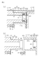
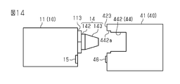
- (A) and (b) are partial cross-sectional views showing a connection portion between the main body unit and the base unit in the first embodiment.
- (A) is a schematic diagram showing a first usage state of the CPAP device in each embodiment
- (b) is a schematic diagram showing a second usage state of the CPAP device.
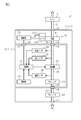
- the explanatory view which shows the structure of the functional block of the CPAP apparatus in the 2nd use state in each embodiment.
- Explanatory drawing which shows the functional block of the CPAP apparatus in each embodiment.
- the explanatory view which shows the outline of the CPAP apparatus of the modification example in 1st Embodiment.
- the explanatory view which shows the outline of the CPAP apparatus of the modification example in 1st Embodiment.
- (A) and (b) are explanatory views showing an example of modification of the base in the first embodiment.
- a perspective view of the CPAP device according to the second embodiment as viewed from another angle. The figure explaining the movable 2nd electrical connection part in 2nd Embodiment.
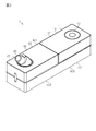
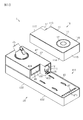
- the CPAP device 1 includes a main body unit 10 as a first unit and a base unit 40 as a second unit.
- the main body unit 10 includes a blower 22 as a main component.
- the base unit 40 includes a humidifier 51 as a main component.
- the base unit 40 is removable from the main body unit 10.
- the CPAP device 1 is configured so that it can be used in the first use state and the second use state.
- the first used state is a state in which the base unit 40 is attached to the main body unit 10
- the second used state is a state in which the base unit 40 is not attached to the main body unit 10.
- the main body unit 10 and the base unit 40 are used.
- the second used state only the main body unit 10 is used, and the base unit 40 is not used.
- the CPAP device 1 of the present embodiment is highly convenient not only at home but also at night by configuring the CPAP device 1 with a plurality of units and the plurality of units being detachably attached to each other. It is intended to demonstrate sexuality.
- the CPAP device 1 can be used in the above-mentioned first usage state by attaching the base unit 40 to the main body unit 10.
- the CPAP device 1 provided with the humidifier 51 can supply humidified air to the user.
- the CPAP device 1 can be used in the second used state in which the base unit 40 is not attached to the main body unit 10. In this second use state, since the CPAP device 1 has only the main body unit 10, it is sufficient to carry only the main body unit 10, and high portability can be obtained.
- the CPAP device 1 can also be used in the second used state when at home.
- the main body unit 10 has a flat substantially rectangular parallelepiped outer shape, and the outer shell thereof is composed of the first housing 11.
- the first housing 11 has an upper surface 111 and a lower surface 112 facing opposite sides in the thickness direction, and four side surfaces 113, 114, 115, 116 connecting the upper surface 111 and the lower surface 112.
- the upper surface 111 is an operation surface provided with the operation unit 12.
- the operation unit 12 includes an annular member and a plurality of switches that are turned on and off by the member. It is formed by turning the switch on and off, and the set value can be changed by the annular operation unit 12.
- the lower surface 112 is a mounting surface that is mounted on the base unit 40 in the first used state and mounted on a floor surface, a table, or the like in the second used state.
- the side surface 113 is a connection surface connected to the base unit 40 in the first use state, and is hereinafter referred to as the first connection surface 113.
- the side surface 113 is orthogonal to the upper surface 111 and the lower surface 112.
- the first introduction unit 13 for introducing the air outside the first housing 11 into the first housing 11 and the inside to the outside of the first housing 11 And a first lead-out unit 14 for leading out air are provided.
- the first out-licensing unit 14 is an example of a first guide unit and a convex portion.
- the first introduction unit 13 has a plurality of through holes. Due to these plurality of through holes, the first housing 11 has a first introduction port 131.
- the first connection surface 113 of the first housing 11 is provided with a first electrical connection portion 15 for electrically connecting the main body unit 10 and the base unit 40.
- the first electrical connection portion 15 electrically connects the main body unit 10 and the base unit 40.
- the first electrical connection portion 15 is a connector having terminals that are connected to and separated from the second electrical connection portion 46 of the base unit 40.
- the base unit 40 includes a second housing 41.
- the second housing 41 has a humidifying portion 42 on which the humidifier 51 shown in FIGS. 6 and 8 is provided, and a mounting portion 43 on which the main body unit 10 is mounted.
- the humidifying portion 42 is formed thicker than the mounting portion 43.
- the lower surface 422 of the humidifying portion 42 and the lower surface 432 of the mounting portion 43 are flush with each other. Therefore, the upper surface 421 of the humidifying portion 42 is located higher than the upper surface 421 of the mounting portion 43.
- the second housing 41 has an elongated substantially rectangular parallelepiped outer shape in which a notch portion 411 is provided in a part in the longitudinal direction by the humidifying portion 42 and the mounting portion 43.
- These lower surfaces 422 and 432 are mounting surfaces that are mounted on a floor surface, a table, or the like in the first use state.
- a second lead-out portion 45 is provided on the upper surface 421 of the humidifying portion 42.
- the second housing 41 has a second outlet 451 that draws air from the inside of the second housing 41 by the second leading unit 45.
- the air tube 2 (see FIGS. 5A and 5B) is connected to the second outlet 45 (second outlet 451) in the first use state.
- the upper surface 431 of the mounting portion 43 is a surface on which the main body unit 10 is mounted. The difference in height between the upper surface 421 of the humidifying portion 42 and the upper surface 431 of the mounting portion 43 corresponds to the thickness of the first housing 11 of the main body unit 10.
- the side surface facing the cutout portion 411 is the second connecting surface 423 to which the main body unit 10 is connected.
- the second connection surface 423 is provided with a second introduction portion 44 for introducing air from the outside of the second housing 41.
- the second introduction portion 44 has a through hole
- the second housing 41 has a second introduction port 441 due to the through hole.
- a second electrical connection portion 46 is provided on the second connection surface 423.
- the second electrical connection portion 46 is electrically connected to the first electrical connection portion 15 of the main body unit 10 by attaching the base unit 40 to the main body unit 10.
- the second electrical connection portion 46 is a connector having a terminal that is connected to and separated from the first electrical connection portion 15.
- the first electrical connection unit 15 and the second electrical connection unit 46 perform electrical connection and disconnection between the main body unit 10 and the base unit 40.
- the first electrical connection unit 15 and the second electrical connection unit 46 are used for supplying power to the base unit 40 and transmitting / receiving data by a digital signal.
- power supply and data transmission / reception can be performed by separate connection units. For example, non-contact power supply, short-range wireless communication, and the like can be used together.
- the upper surface 431 of the mounting portion 43 of the second housing 41 described above is provided with a third introduction portion 47 that introduces air from the outside of the second housing 41.
- the third introduction portion 47 has a plurality of through holes penetrating the second housing 41, and the second housing 41 has a third introduction port 471 due to the plurality of through holes.
- the second connection surface 423 is provided with a third lead-out unit 48 for leading out air from the second housing 41.
- the third outlet 48 has a through hole that penetrates the second housing 41, and the second housing 41 has a third outlet 481 due to this through hole.
- the main body unit 10 By arranging the main body unit 10 in the cutout portion 411 of the base unit 40, the lower surface 112 of the first housing 11 and the upper surface 431 of the mounting portion 43 of the second housing 41 face each other, and the first housing The first connection surface 113 of the body 11 and the second connection surface 423 of the second housing 41 face each other. Then, the first lead-out unit 14 provided on the first connection surface 113 of the first housing 11 and the second introduction unit 44 provided on the second connection surface 423 of the second housing 41 are connected to each other. .. Further, the first introduction unit 13 provided on the first connection surface 113 of the first housing 11 and the third lead-out unit 48 provided on the second connection surface 423 of the second housing 41 are connected to each other. ..
- the CPAP device 1 has a substantially rectangular parallelepiped shape as a whole. Then, the air introduced into the second housing 41 by the third introduction unit 47 of the second housing 41 is the third leading unit 48 of the second housing 41 and the first introduction unit 13 of the first housing 11. It is introduced into the first housing 11 via and. Then, the air in the first housing 11 is introduced into the second housing 41 via the first lead-out unit 14 of the first housing 11 and the second introduction unit 44 of the second housing 41. Then, it is led out from the second out-licensing unit 45 of the second housing 41 to the outside.
- the main body unit 10 when the base unit 40 is not attached to the main body unit 10, the first connection surface 113 of the first housing 11 is exposed to the outside. Therefore, the first introduction section 13 and the first lead-out section 14 provided on the first connection surface 113 of the first housing 11 are in a state of being open to the outside. As a result, the main body unit 10 introduces air from the outside of the first housing 11 into the first housing 11 by the first introduction unit 13, and the air in the first housing 11 is external from the first lead-out unit 14. Derived to. That is, the main body unit 10 functions independently as a CPAP device.
- the first out-licensing unit 14 projects from the first connecting surface 113.
- the first out-licensing unit 14 includes a base portion 142 and a connecting cylinder portion 143.
- the base 142 is connected to the first connection surface 113.
- the connecting cylinder portion 143 extends from the base portion 142 in the direction opposite to the first connecting surface.
- the base 142 is formed in a cylindrical shape.
- the outer peripheral surface of the base portion 142 is a cylindrical surface, and the external dimensions of the base portion 142 are the same in the direction of projecting from the side of the first connecting surface 113.
- the connecting cylinder portion 143 is formed in a tapered shape in which the outer diameter dimension becomes smaller toward the tip end.
- the first lead-out portion 14 has a base portion 142 having a cylindrical peripheral surface and a connecting cylinder portion 143 having a tapered peripheral surface.
- connection cylinder portion 143 is formed with a connection recess 144 from the tip thereof toward the base portion 142. Through holes penetrating the base portion 142, the connecting cylinder portion 143, and the connecting recess 144 communicate the outside and the inside of the first housing 11.
- the first housing 11 has a first outlet 141 that guides air to the outside of the first housing 11 by the first lead-out unit 14.
- the second introduction portion 44 has a housing portion 442 and a connecting convex portion 444.
- the accommodating portion 442 is an example of a second guide portion and a recess.
- the accommodating portion 442 is recessed from the second connection surface 423 of the second housing 41 toward the inside of the second housing 41. As shown in FIG. 4A, the accommodating portion 442 accommodates the first lead-out portion 14 of the first housing 11.
- the accommodating portion 442 has an inner wall 443a and a wall portion 443b.
- the inner wall 443a has a cylindrical shape, and the inner diameter dimension thereof is set to be slightly larger than the outer diameter dimension of the base portion 142 of the first lead-out portion 14. That is, the CPAP device 1 has a gap (clearance) GA between the inner wall 443a (inner surface) of the accommodating portion 442 and the peripheral surface of the base portion 142 of the first lead-out portion 14.
- the size of the gap GA is the distance between the base 142 of the first lead-out unit 14 and the inner wall 443a of the accommodating unit 442, and the distance depends on the first electrical connection portion 15 and the second electrical connection portion 46. It is set.
- a connecting convex portion 444 is provided on the wall portion 443b of the accommodating portion 442.
- the connecting convex portion 444 projects toward the open end of the accommodating portion 442.
- the connecting convex portion 444 is formed in a cylindrical shape.
- the second housing 41 has a second introduction port 441 that introduces air into the inside of the second housing 41 by the connecting convex portion 444.
- a sealing member 445 is provided on the outer peripheral surface of the connecting convex portion 444.
- the sealing member 445 is housed in a groove provided along the outer peripheral surface of the connecting convex portion 444.
- the sealing member 445 is in close contact with the inner peripheral surface of the connection recess 144 of the first lead-out portion 14 of the first housing 11.
- the sealing member 445 is, for example, an annular sealing member.
- the sealing member 445 seals between the connecting convex portion 444 and the connecting concave portion 144. That is, the sealing member 445 prevents air from leaking between the first lead-out unit 14 and the second introduction unit 44.
- the first housing 11 is provided with a first electrical connection portion 15.
- the first electrical connection portion 15 is a female connector and is internally provided in the first housing 11 so as not to protrude from the first connection surface 113.
- the second housing 41 is provided with a second electrical connection portion 46.
- a part of the second electrical connection portion 46 projects from the second connection surface 423 of the second housing 41.
- the second electrical connection portion 46 is a male connector.
- the second electrical connection portion 46 is inserted into the first electrical connection portion 15.
- the main body unit 10 and the base unit 40 are electrically connected by the first electrical connection portion 15 and the second electrical connection portion 46.
- the length L14 of the first lead-out unit 14 is the length from the first connection surface 113 of the first housing 11 to the tip of the first lead-out unit 14.
- the length L46 of the second electrical connection portion 46 is the length from the second connection surface 423 of the second housing 41 to the tip of the second electrical connection portion 46.
- the length L14 of the first lead-out unit 14 is longer than the length L46 of the second electrical connection unit 46. Therefore, when the base unit 40 is attached to the main body unit 10, the tip of the first lead-out unit 14 is first inserted into the second introduction unit 44, and then the second electrical connection unit 46 is inserted into the first electrical connection unit 15. To.
- the first lead-out portion 14 has a base portion 142 having a cylindrical peripheral surface and a connecting cylinder portion 143 having a tapered peripheral surface.
- the first lead-out unit 14 moves toward the center of the second introduction unit 44 by the connecting cylinder portion 143 having a tapered peripheral surface.
- the first lead-out unit 14 can be inserted into the connection concave portion 144 of the first lead-out unit 14 so that the connection convex portion 444 of the second introduction unit 44 can be inserted. Will be guided.
- the first electrical connection unit 15 of the first housing 11 and the second electrical connection unit 46 of the second housing 41 are electrically connected to each other.
- the first out-licensing unit 14 is guided to a position where it is possible.
- the outer diameter dimension of the connecting cylinder portion 143 on the side of the base portion 142 is equal to the outer diameter dimension of the base portion 142.
- the outer dimension of the base 142 is smaller than the inner diameter of the accommodating portion 442 of the second housing 41. Therefore, as shown in FIG. 4A, the base 142 is inserted into the accommodating portion 442. Then, a gap (clearance) GA is generated between the outer peripheral surface of the base portion 142 and the inner peripheral surface of the accommodating portion 442.
- the first housing 11 and the second housing 41 can be relatively moved along the first connection surface 113 and the second connection surface 423. This movement enables further alignment of the first electrical connection portion 15 and the second electrical connection portion 46.
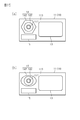
- FIG. 5 (a) and 5 (b) schematically show the usage state of the CPAP device 1 of the present embodiment.
- FIG. 5A shows a first usage state
- FIG. 5B shows a second usage state.
- the CPAP device 1 in the first use state, is used in a state where the base unit 40 is attached to the main body unit 10.
- the first end portion of the air tube 2 is connected to the second lead-out portion 45 provided in the base unit 40, and the second end portion of the air tube 2 is connected to the mask 3.
- the mask 3 is worn, for example, so as to cover the nose or mouth of the user 4.
- the CPAP device 1 is used only for the main body unit 10 to which the base unit 40 is not attached.
- the first end portion of the air tube 2 is connected to the first lead-out portion 14 provided in the main body unit 10, and the second end portion of the air tube 2 is connected to the mask 3.
- the mask 3 is worn, for example, so as to cover the nose or mouth of the user 4.
- FIG. 6 shows the configuration of the functional block in the first used state of the CPAP device 1 of the present embodiment
- FIG. 7 shows the configuration of the functional block in the second used state of the CPAP device 1.
- the main body unit 10 of the CPAP device 1 includes a first control unit 21, an operation unit 12, a blower 22, a silencer 23, a flow rate sensor 24, a pressure sensor 25, and a temperature sensor 26. ..
- the base unit 40 includes a humidifier 51, a silencer 52, and a second control unit 53.
- the main body unit 10 includes a first flow path 16 between the first introduction unit 13 and the first lead-out unit 14.
- a blower 22 is provided in the first flow path 16.
- the blower 22 is composed of, for example, a centrifugal fan.
- the blower 22 is installed in the blower room provided in the first housing 11.
- the blower room is a part of the first flow path 16, and the blower room 22 is arranged on the first flow path 16.
- a silencer 23 is provided between the first introduction unit 13 and the blower 22 in the first flow path 16.
- the silencer 23 suppresses leakage of noise generated by the blower 22 (operating noise of the drive motor, wind noise, etc.) to the outside of the first housing 11.
- the pressure sensor 25, the flow rate sensor 24, and the temperature sensor 26 are provided in the first flow path 16.
- the pressure sensor 25 is a sensor for detecting the pressure of the air sent out by the blower 22.
- the flow rate sensor 24 is a sensor for detecting the flow rate of air between the main body unit 10 and the air tube 2.
- the temperature sensor 26 is a sensor for detecting the temperature of the air introduced from the outside of the main body unit 10.
- the first control unit 21 operates an arithmetic processing unit (CPU: Central Processing Unit) for executing a program, a storage unit (ROM: Read Only Memory / RAM: Random Access Memory), a communication unit, and a blower 22 as main components. Includes a drive unit, etc.
- the storage unit includes a ROM that stores data non-volatilely and a RAM that stores data volatilely.
- the data stored in the storage unit is data generated by executing a program by the arithmetic processing unit, data input via the operation unit 12, data measured by the various sensors described above, and external communication by the communication unit. Includes data sent and received between.
- the processing in the arithmetic processing unit is realized by each hardware and the software executed by the arithmetic processing unit.
- Such software is stored in advance in the storage unit.
- Accepting the operation of the operation unit 12, controlling the drive motor that drives the blower 22, communication with the outside, and the like are also realized by software.
- the first control unit 21 increases or decreases the rotation speed of the blower 22 by control such as feedback control and feedforward control based on the flow rate value and the pressure value detected by the flow rate sensor 24 and the pressure sensor 25. , Control the amount of air sent out, etc.
- the first control unit 21 determines the exhalation state of the user based on the values measured by the flow rate sensor 24 and the pressure sensor 25, and the pressure value of the air supplied to the user so as to synchronize with the exhalation state. To control. Further, the first control unit 21 transmits the temperature value detected by the temperature sensor 26 to the outside.
- the second housing 41 of the base unit 40 has a second flow path 49 between the second introduction section 44 and the second lead-out section 45, and a third section between the third introduction section 47 and the third lead-out section 48. It is provided with a flow path 50.
- a humidifier 51 is provided in the second flow path 49. The humidifier 51 adds humidity to the air flowing through the second flow path 49 in the first use state. As a result, the CPAP device 1 imparts appropriate moisture to the air sent out toward the user's respiratory tract.
- the humidifier 51 is a heating type humidifier.
- the humidifier 51 includes a container 511, a heater 512, and a temperature sensor 513.
- the container 511 is configured to be removable from the second housing 41.
- Container 511 stores water.
- the container 511 has an introduction pipe communicating with the second introduction portion 44, and air is supplied into the container 511 through the introduction pipe.
- the container 511 has a heater pad corresponding to the heater 512.
- the heater 512 heats the water in the container 511.
- the temperature sensor 513 detects the temperature of the heater 512.
- the second control unit 53 operates an arithmetic processing unit (CPU), a storage unit (ROM / RAM), a communication unit, and a humidifier 51 for executing a program as main components. Includes a drive unit, etc.
- the storage unit includes a ROM that stores data non-volatilely and a RAM that stores data volatilely.
- the data stored in the storage unit is the data generated by the execution of the program by the arithmetic processing unit, the heater temperature measured by the temperature sensor 513, and the transmission / reception between the communication unit and the first control unit 21 in the first usage state. Includes data, etc.
- the data received from the first control unit 21 includes the temperature value of air measured by the temperature sensor 26 of the main unit 10.
- the data received from the first control unit 21 may include data input via the operation unit 12.
- the processing in the arithmetic processing unit is realized by each hardware and the software executed by the arithmetic processing unit. Such software is stored in advance in the storage unit. Control of the heater 512 of the humidifier 51, communication with the first control unit 21, and the like are also realized by software.
- the second control unit 53 sets a target temperature for heating the water in the container 511 based on the temperature of the air received from the first control unit 21.
- the second control unit 53 sets the target temperature by, for example, a table or a calculation formula stored in the storage unit.
- the second control unit 53 drives the heater 512 so that the heater temperature becomes the target temperature by control such as feedback control and feedforward control based on the heater temperature detected by the temperature sensor 513.
- the water temperature in the container 511 is adjusted by the heater 512. This gives the air passing through the container 511 the desired humidity.
- the second control unit 53 may stop the humidifier 51, that is, stop the control of the heater 512, based on the temperature of the air received from the first control unit 21.
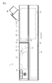
- a silencer 52 is provided in the third flow path 50. As shown in FIG. 8, the silencer 52 is provided in the mounting portion 43 on which the main body unit 10 is mounted in the base unit 40.
- the silencer 52 has a size slightly smaller than the size (outer shape) of the main body unit 10. As the volume of the silencer 52 increases, the quietness of the CPAP device 1 is enhanced.
- the silencer 52 is composed of, for example, a resonance tube branched from the third flow path 50.
- the resonance tube is composed of a meandering flow path.
- the resonance tube is also called a Helmholtz resonator or a resonator, and has a function of attenuating noise in a predetermined frequency band.
- the resonant tube attenuates sound in a frequency band determined by its natural frequency.
- the main body unit 10 includes a power supply unit 55.
- An AC adapter (not shown) is connected to the power supply unit 55.
- the power supply unit 55 generates the operating power required for the main unit 10 and the base unit 40.
- the operating power is supplied to the second control unit 53 of the base unit 40 and the like via the first electrical connection unit 15 of the main unit 10 and the second electrical connection unit 46 of the base unit 40.
- the CPAP device 1 includes a main body unit 10 and a base unit 40 attached to the main body unit 10.
- the CPAP device 1 When the CPAP device 1 is at home, the CPAP device 1 can be used in the above-mentioned first usage state by attaching the base unit 40 to the main body unit 10. In this first use state, by attaching the base unit 40 to the main body unit 10, the CPAP device 1 provided with the humidifier 51 can supply humidified air to the user. When staying out, the CPAP device 1 can be used in a second use state in which the base unit 40 is not attached to the main body unit 10. In this second use state, since the CPAP device 1 has only the main body unit 10, it is sufficient to carry only the main body unit 10, and high portability can be obtained.
- the first housing 11 of the main body unit 10 has a first introduction unit 13, a first lead-out unit 14, and a first electrical connection unit 15.
- the first lead-out unit 14 and the first electrical connection unit 15 are provided on the first connection surface 113 of the first housing 11.
- the second housing 41 of the base unit 40 has a second introduction section 44, a second lead-out section 45, and a second electrical connection section 46.
- the second introduction unit 44 and the second electrical connection unit 46 are provided on the second connection surface 423 facing the first connection surface 113 of the first housing 11 in the first use state.
- the first out-licensing unit 14 has an annular base portion 142 and a connecting cylinder portion 143 extending from the base portion 142.
- the connecting cylinder portion 143 is formed in a tapered shape in which the outer diameter dimension becomes smaller toward the tip end.
- the first lead-out portion 14 has a base portion 142 having a cylindrical peripheral surface and a connecting cylinder portion 143 having a tapered peripheral surface.
- the first out-licensing unit 14 includes a base portion 142 and a connecting cylinder portion 143.
- the base 142 is connected to the first connection surface 113.
- the connecting cylinder portion 143 extends from the base portion 142 in the direction opposite to the first connecting surface.
- the base 142 is formed in a cylindrical shape.
- the outer peripheral surface of the base portion 142 is a cylindrical surface, and the external dimensions of the base portion 142 are the same in the direction of projecting from the side of the first connecting surface 113.
- the connecting cylinder portion 143 is formed in a tapered shape in which the outer diameter dimension becomes smaller toward the tip end.
- the second introduction portion 44 has a housing portion 442 and a connecting convex portion 444.
- the accommodating portion 442 is recessed from the second connection surface 423 of the second housing 41 toward the inside of the second housing 41. As shown in FIG. 4A, the accommodating portion 442 accommodates the first lead-out portion 14 of the first housing 11.
- the first lead-out unit 14 When the first lead-out unit 14 is inserted into the second introduction unit 44, the first lead-out unit 14 moves toward the center of the second introduction unit 44 by the connecting cylinder portion 143 having a tapered peripheral surface. By moving the first lead-out unit 14 with respect to the second introduction unit 44, the first lead-out unit 14 can be inserted into the connection concave portion 144 of the first lead-out unit 14 so that the connection convex portion 444 of the second introduction unit 44 can be inserted. Will be guided. Therefore, the first derivation unit 14 and the second introduction unit 44 can be easily connected.
- the first lead-out unit 14 with respect to the second introduction unit 44 by moving the first lead-out unit 14 with respect to the second introduction unit 44, the first electrical connection unit 15 of the first housing 11 and the second electrical connection unit 46 of the second housing 41 can be electrically connected to each other.
- the first housing 11 and the second housing 41 are relatively guided to such positions. That is, the first lead-out unit 14 and the second introduction unit 44 guide the first electrical connection unit 15 and the second electrical connection unit 46 to positions where they can be electrically connected to each other, the first guide unit and the second guide unit. Functions as. With such a configuration, the first electrical connection portion 15 and the second electrical connection portion 46 can be easily connected.
- the outer diameter dimension of the connecting cylinder portion 143 on the side of the base portion 142 is equal to the outer diameter dimension of the base portion 142.
- the outer dimension of the base 142 is smaller than the inner diameter of the accommodating portion 442 of the second housing 41. Therefore, as shown in FIG. 4A, the base 142 is inserted into the accommodating portion 442. Then, a gap (clearance) GA is generated between the outer peripheral surface of the base portion 142 and the inner peripheral surface of the accommodating portion 442.
- the first housing 11 and the second housing 41 can be relatively moved along the first connection surface 113 and the second connection surface 423. This movement enables further alignment of the first electrical connection portion 15 and the second electrical connection portion 46.
- connection recess 144 is formed in the connection cylinder portion 143 of the first lead-out portion 14 from the tip thereof toward the base portion 142. Through holes penetrating the base portion 142, the connecting cylinder portion 143, and the connecting recess 144 communicate the outside and the inside of the first housing 11.
- the first housing 11 has a first outlet 141 that guides air to the outside of the first housing 11 by the first lead-out unit 14.
- the connecting convex portion 444 of the second introduction portion 44 is provided on the wall portion 443b of the accommodating portion 442.
- the connecting convex portion 444 projects toward the open end of the accommodating portion 442.
- the connecting convex portion 444 is formed in a cylindrical shape.
- the second housing 41 has a second introduction port 441 that introduces air into the inside of the second housing 41 by the connecting convex portion 444.
- a sealing member 445 is provided on the outer peripheral surface of the connecting convex portion 444.
- the sealing member 445 is housed in a groove provided along the outer peripheral surface of the connecting convex portion 444.
- the sealing member 445 is in close contact with the inner peripheral surface of the connection recess 144 of the first lead-out portion 14 of the first housing 11.
- the sealing member 445 is, for example, an annular sealing member.
- the sealing member 445 seals between the connecting convex portion 444 and the connecting concave portion 144. That is, the sealing member 445 prevents air from leaking between the first lead-out unit 14 and the second introduction unit 44.
- the second control unit 53 of the base unit 40 controls the humidifier 51 provided in the base unit 40. Therefore, the first control unit 21 of the main body unit 10 may control the blower 22 provided in the main body unit 10 and accept the operation of the operation unit 12. Therefore, the calculation load of the first control unit 21 and the like can be suppressed lower than that of the first control unit 21 that controls the entire CPAP device 1, and heat generation can be suppressed.
- the main body unit 10 when the base unit 40 is attached to the main body unit 10, the main body unit 10 is at a predetermined distance (for example, about 1.5 mm) from the upper surface 431 of the mounting portion 43 of the base unit 40. They are placed apart from each other.
- the third introduction unit 47 (see FIGS. 1 and 2) provided in the base unit 40 communicates with the space outside the CPAP device 1 through the gap between the base unit 40 and the main body unit 10. .. Therefore, intake can be efficiently performed without limiting the direction, and the main body unit 10 is located facing the third introduction unit 47 to suppress the leakage of noise from the third introduction unit 47 to the outside. Will be done.
- the CPAP device 1 can be used in the above-mentioned first usage state by attaching the base unit 40 to the main body unit 10 when at home. In this first use state, by attaching the base unit 40 to the main body unit 10, the CPAP device 1 provided with the humidifier 51 can supply humidified air to the user. When staying out, the CPAP device 1 can be used in a second use state in which the base unit 40 is not attached to the main body unit 10. In this second use state, since the CPAP device 1 has only the main body unit 10, it is sufficient to carry only the main body unit 10, and high portability can be obtained.
- the first out-licensing unit 14 includes a base portion 142 and a connecting cylinder portion 143.
- the base 142 is connected to the first connection surface 113.
- the connecting cylinder portion 143 extends from the base portion 142 in the direction opposite to the first connecting surface.
- the base 142 is formed in a cylindrical shape.
- the outer peripheral surface of the base portion 142 is a cylindrical surface, and the external dimensions of the base portion 142 are the same in the direction of projecting from the side of the first connecting surface 113.
- the connecting cylinder portion 143 is formed in a tapered shape in which the outer diameter dimension becomes smaller toward the tip end.
- the second introduction portion 44 has a housing portion 442 and a connecting convex portion 444.
- the accommodating portion 442 is recessed from the second connection surface 423 of the second housing 41 toward the inside of the second housing 41.
- the first lead-out unit 14 of the first housing 11 is housed in the storage unit 442.
- the first lead-out unit 14 when the first lead-out unit 14 is inserted into the second introduction unit 44, the first lead-out unit 14 moves toward the center of the second introduction unit 44 by the connecting cylinder portion 143 having a tapered peripheral surface. To do.
- the first lead-out unit 14 By moving the first lead-out unit 14 with respect to the second introduction unit 44, the first lead-out unit 14 can be inserted into the connection concave portion 144 of the first lead-out unit 14 so that the connection convex portion 444 of the second introduction unit 44 can be inserted. Will be guided. Therefore, the first derivation unit 14 and the second introduction unit 44 can be easily connected.
- the first electrical connection unit 15 of the first housing 11 and the second electrical connection unit 46 of the second housing 41 are electrically connected to each other.
- the first housing 11 and the second housing 41 are relatively guided to the possible positions. That is, the first lead-out unit 14 and the second introduction unit 44 guide the first electrical connection unit 15 and the second electrical connection unit 46 to positions where they can be electrically connected to each other, the first guide unit and the second guide unit. Functions as. With such a configuration, the first electrical connection portion 15 and the second electrical connection portion 46 can be easily connected.
- the outer diameter dimension of the connecting cylinder portion 143 on the side of the base portion 142 is equal to the outer diameter dimension of the base portion 142.
- the outer dimension of the base 142 is smaller than the inner diameter of the accommodating portion 442 of the second housing 41. Therefore, as shown in FIG. 4A, the base 142 is inserted into the accommodating portion 442. Then, a gap (clearance) GA is generated between the outer peripheral surface of the base portion 142 and the inner peripheral surface of the accommodating portion 442.
- the first housing 11 and the second housing 41 can be relatively moved along the first connection surface 113 and the second connection surface 423. This movement enables further alignment of the first electrical connection portion 15 and the second electrical connection portion 46.
- a sealing member 445 is provided on the outer peripheral surface of the connecting convex portion 444.
- the sealing member 445 is housed in a groove provided along the outer peripheral surface of the connecting convex portion 444.
- the sealing member 445 is in close contact with the inner peripheral surface of the connection recess 144 of the first lead-out portion 14 of the first housing 11.
- the sealing member 445 is, for example, an annular sealing member.
- the sealing member 445 seals between the connecting convex portion 444 and the connecting concave portion 144. That is, the sealing member 445 can prevent air from leaking between the first lead-out unit 14 and the second introduction unit 44. Further, by providing the sealing member 445 on the connecting convex portion 444 in the accommodating portion 442 of the base unit 40, it is possible to prevent the sealing member 445 from being damaged or lost when the main body unit 10 is carried.
- the main body unit 10 In the first use state in which the base unit 40 is attached to the main body unit 10, the main body unit 10 is at a predetermined distance (for example, about 1.5 mm) from the upper surface 431 of the mounting portion 43 of the base unit 40. It is placed separated by. As a result, the third introduction unit 47 (see FIGS. 1 and 2) provided in the base unit 40 communicates with the space outside the CPAP device 1 through the gap between the base unit 40 and the main body unit 10. .. Therefore, the direction is not limited, the intake air can be efficiently taken, and the main body unit 10 is located facing the third introduction unit 47 to suppress the leakage of noise from the third introduction unit 47 to the outside. it can.
- a predetermined distance for example, about 1.5 mm
- the lower surface 112 of the first housing 11 is placed on the base unit 40 in the first use state, and is placed on the floor surface, table, or the like in the second use state.
- the third connection surface 112 is orthogonal to the first connection surface 113 and is adjacent to the first connection surface 113.
- the first connection surface 113 of the first housing 11 is provided with a first introduction unit 13 for introducing the air outside the first housing 11 into the first housing 11.
- the first introduction unit 13 is composed of a plurality of through holes.
- a first lead-out section 201 that draws air from the inside to the outside of the first housing 11 is provided.
- the first out-licensing unit 201 protrudes from the first connection surface 113.
- the first out-licensing unit 201 has a cylindrical shape.
- On the outer peripheral surface of the first lead-out unit 201 a groove is recessed at a portion in contact with the first connection surface 113.
- An annular sealing member 204 is fitted in the groove.
- first guide portions 202 protrude from the first connection surface 113 of the first housing 11.
- the first guide unit 202 is located above the first lead unit 201 and the first introduction unit 13. Further, the first guide portion 202 is provided at both ends in the width direction orthogonal to the vertical direction of the first connection surface 113 when the first connection surface 113 is viewed in a plan view. That is, one first guide portion 202 is provided at each upper corner portion of the first connection surface 113. Further, the first guide portion 202 has a substantially L-shape so as to follow the shape of the square portion when viewed in a plan view from a direction orthogonal to the first connection surface 113. The length of the first guide unit 202 protruding from the first connection surface 113 is substantially the same as the length of the first lead-out unit 201 protruding from the first connection surface 113.
- a first electrical connection portion 203 for electrically connecting the main body unit 10 and the base unit 40 is provided at substantially the center of the third connection surface 112 of the first housing 11. There is.
- the first electrical connection portion 203 is a female connector, and is internally provided in the first housing 11 so as not to protrude from the first connection surface 113.
- the base unit 40 includes a second housing 41.
- the upper surface 431 of the mounting portion 43 is a fourth connecting surface 431 that faces the third connecting surface 112 of the first housing 11 in the vertical direction in the first use state.
- the second connection surface 423 of the second housing 41 is provided with a second introduction portion 44 for introducing air from the outside of the second housing 41.
- the second introduction portion 44 is a through hole that penetrates the inside and outside of the second housing 41.
- the second connection surface 423 is provided with a third lead-out unit 48 for introducing air from the second housing 41.
- the third lead-out unit 48 is a through hole that penetrates the inside and outside of the second housing 41.
- the second guide portion 602 is a through hole that penetrates the inside and outside of the second housing 41.
- the second guide unit 602 is located above the third lead unit 48 and the second introduction unit 44.
- the second guide portion 602 is provided at both ends in the width direction orthogonal to the vertical direction of the second connection surface 423 when the second connection surface 423 is viewed in a plan view. That is, one second guide portion 602 is provided at each upper corner portion of the second connection surface 423.
- the second guide portion 602 has a substantially L shape when viewed from a direction orthogonal to the second connection surface 423 so that the first guide portion 202 fits.
- the outer wall 650 projects upward from the fourth connection surface 431.
- the outer wall 650 extends along three sides of the outer edge of the fourth connecting surface 431, excluding the boundary between the second connecting surface 423 and the fourth connecting surface 431.
- the protruding length of the outer wall 650 from the fourth connecting surface 431 is, for example, about several mm to a dozen mm.
- third guide portions 652 project upward from the fourth connection surface 431.
- the third guide portion 652 is arranged on the edge of the fourth connection surface 431. Therefore, the third guide portion 652 is connected to the above-mentioned outer wall 650.
- Two third guide portions 652 are arranged on each of the three sides of the fourth connection surface 431 on which the outer wall 650 is present. Therefore, when the fourth connection surface 431 is viewed from above, two third guide portions 652 are present on each of the pair of long sides of the fourth connection surface 431 facing in the lateral direction.
- the third guide portion 652 has a flat plate shape.
- the third guide portion 652 has a trapezoidal shape in which the side on the fourth connection surface 431 side is the long side and the upper side is the short side when viewed in a plan view.
- the side of the third guide portion 652 on the center side of the fourth connection surface 431 is inclined toward the center side of the fourth connection surface 431 from the short side to the long side. That is, the central edge of the fourth connection surface 431 of the third guide portion 652 faces the first housing 11 side in the first use state, and the center of the fourth connection surface 431 from the tip to the base end. It is an inclined portion 653 that inclines toward the side.
- the hole 701 is recessed at substantially the center of the fourth connection surface 431 in the second housing 41.
- a second electrical connection portion 603 is arranged in the hole portion 701. The second electrical connection unit 603 comes into contact with the first electrical connection unit 203 in the first use state.
- the second electrical connection unit 603 is a male connector having a terminal that is connected to and separated from the first electrical connection unit 203.
- a spring 700 as an elastic member is housed in the bottom of the hole 701.
- the spring 700 is interposed between the bottom surface of the hole 701 and the second electrical connection 603.
- the shape of the spring 700 is simplified.
- the spring 700 urges the second electrical connection portion 603 upward.
- the second electrical connection portion 603 is urged by the spring 700 and projects upward from the fourth connection surface 431.
- the second electrical connection portion 603 is movable in the direction orthogonal to the fourth connection surface 431.
- the first electrical connection unit 203 and the second electrical connection unit 603 electrically connect and disconnect the main unit 10 and the base unit 40.
- the first electrical connection unit 203 and the second electrical connection unit 603 are used for supplying power to the base unit 40 and transmitting / receiving data by a digital signal.
- power supply and data transmission / reception can be performed by separate connection units. For example, non-contact power supply, short-range wireless communication, and the like can be used together.
- both the third connection surface 112 and the fourth connection surface 431 have a substantially rectangular shape, but the third connection surface 112 is smaller in size than the fourth connection surface 431. It has become. Specifically, the dimension of the third connection surface 112 in the longitudinal direction is shorter than that of the fourth connection surface 431 by about one long side of the third guide portion 652. Further, the width dimension of the third connection surface 112 in the width direction is shorter than that of the fourth connection surface 431 by about two long sides of the third guide portion 652.
- the base unit 40 When attaching the base unit 40 to the main body unit 10, first, by tilting the base unit 40 and approaching it from diagonally above, a part of the tip end side of the first guide portion 202 is inserted into the inside of the second guide portion 602. Then, with the tip of the first guide portion 202 inserted into the second guide portion 602 as a fulcrum, the third connection surface 112 of the first housing 11 and the fourth connection surface 431 of the second housing 41 come close to each other. The first housing 11 is rotated. When the first housing 11 is rotated, the first lead-out unit 201 protruding from the first connection surface 113 is housed inside the second introduction unit 44 penetrating the second connection surface 423. Then, when the first housing 11 is further rotated, the first guide portion 202 is also gradually inserted into the inside of the second guide portion 602, and finally, substantially the entire first guide portion 202 is second. It is inserted inside the guide portion 602.
- the first out-licensing unit 201 is the outer circumference of the first out-licensing unit 201. It is connected to the second introduction portion 44 without a gap by the sealing member 204 provided in the above. Further, at the same time that the first lead-out unit 201 and the second introduction unit 44 are connected, the first introduction unit 13 and the third lead-out unit 48 are connected to each other.
- the third connecting surface 112 has the width of the fourth connecting surface 431. It comes into contact with the third guide portion 652 on either side arranged in the direction.
- the third connecting surface 112 guides the third connecting surface 112 toward the center side of the fourth connecting surface 431 by sliding the inclined portion 653 of the third guide portion 652. While being done, it approaches the fourth connection surface 431.
- the two third guide portions 652 arranged in the longitudinal direction of the fourth connection surface 431 may come into contact with the third connection surface 112.
- the inclined portion 653 of the third guide portion 652 guides the first housing 11 in the direction in which the first connection surface 113 approaches the second connection surface 423.
- the second electrical connection portion 603 is pressed by the third connection surface 112 and moves so as to be stored inside the second housing 41. .. That is, when the first housing 11 presses the second electrical connection portion 603 by the rotation of the first housing 11, the spring 700 provided inside the second housing 41 contracts, and the second electrical connection portion 603 Moves down.
- the third connection surface 112 and the fourth connection surface 431 are in the closest state, and the second electrical connection unit 603 is the first. 1 Contact with the electrical connection portion 203, and the first electrical connection portion 203 and the second electrical connection portion 603 are electrically connected.
- the first housing 11 When attaching the base unit 40 to the main body unit 10, the first housing 11 is rotated and attached with the first guide portion 202 and the second guide portion 602 as fulcrums. At that time, it is important to rotate the first housing 11 while aligning the members of the first housing 11 and the members of the second housing 41 so as to connect to each other. For example, it is preferable that the first lead-out unit 201 and the second introduction unit 44 are attached without being obliquely displaced so that the first lead-out unit 201 is connected to the second introduction unit 44 without a gap. Further, the connection between the first electrical connection unit 203 and the second electrical connection unit 603 needs to be in proper contact with each other so that they can be electrically connected.
- the first lead-out unit 201 is provided on the first connection surface 113, and the first electrical connection unit 203 is provided on the third connection surface 112. Therefore, the operation of connecting the first out-licensing unit 201 and the operation of connecting the first electrical connection unit 203 can be performed at different timings. Therefore, it is convenient to attach the base unit 40 to the main body unit 10.
- the first guide unit 202 is arranged on the first connection surface 113 above the first lead unit 201 and the first introduction unit 13.
- the second guide portion is arranged on the second connection surface 423 above the third lead-out portion 48 and the second introduction portion 44. Therefore, if the first connection surface 113 and the second connection surface 423 are brought close to each other when the base unit 40 is attached to the main body unit 10 from diagonally above, the tip of the first guide portion 202 can be easily inserted into the second guide portion 602. ..
- the first guide portion 202 is provided on both ends of the first connection surface 113 in the width direction of the first connection surface 113.
- the second guide portion 602 is provided at both ends of the second connection surface 423 in the width direction of the second connection surface 423.
- the second electrical connection portion 603 is movable with respect to the fourth connection surface 431 in a direction orthogonal to the fourth connection surface 431. Therefore, it is possible to prevent the second electrical connection portion 603 from being damaged or the like due to the impact when the base unit 40 is attached to the main body unit 10.
- the spring 700 is arranged under the second electrical connection portion 603.
- the spring 700 is urged so that the second electrical connection portion 603 projects upward from the fourth connection surface 431.
- the second electrical connection portion 603 is urged upward by the spring 700, so that it automatically returns to the original position where it protruded.
- the second electrical connection portion 603 is urged upward, the second electrical connection portion 603 is pressed against the first electrical connection portion 203 in the first use state, and both are electrically connected. You can make a reliable connection.
- the third guide portion 652 faces the third connection surface 112 side in the first use state, and toward the center side of the fourth connection surface 431 from the protruding tip toward the base end. It has an inclined portion 653 that is inclined. Due to the presence of the third guide portion 652, when the first housing is to be attached in a state where the third connection surface 112 is displaced with respect to the width direction of the fourth connection surface 431, the inclined portion of the third guide portion 652 The 653 guides the first housing 11 in the inclined direction. Therefore, the first housing 11 can be attached to the second housing 41 at a correct position.
- the third guide portion 652 is provided on each of two opposing sides of the fourth connection surface 431 excluding the boundary with the second connection surface 423. Have been placed. If at least one third guide portion 652 is arranged on the pair of sides as in the present embodiment, the third connection surface 112 is connected to the fourth when the base unit 40 is attached to the main body unit 10. The third guide portion 652 can guide the first housing 11 to the correct position regardless of which side the surface 431 is displaced in the width direction.
- the third guide portion 652 is arranged on the edge of the fourth connection surface 431, and the third guide portion 652 is connected to the outer wall 650. In this state, since the third guide portion 652 and the outer wall 650 reinforce each other, the third guide portion 652 and the outer wall 650 are less likely to be damaged even when an external force is applied.
- the accommodating portion 442 of the second introduction portion 44 can be used as the second introduction port.
- the first electrical connection unit 15 and the second electrical connection unit 46 can be easily aligned and connected.
- one sealing member 445 may be provided in the opening portion of the accommodating portion 442 which is the second introduction port.
- the sealing member 445 seals between the accommodating portion 442 and the base portion 142 of the first lead-out portion 14. Further, when the first lead-out portion 14 is accommodated in the accommodating portion 442, the sealing member 445 comes into contact with the connection cylinder portion 143 of the first lead-out portion 14, so that the misalignment of the first lead-out portion 14 can be reduced. ..
- one sealing member 445 may be provided on the base 142 of the first lead-out unit 14.
- three sealing members 445 may be provided in the opening portion of the accommodating portion 442 which is the second introduction port. Further, as shown in FIG. 13, three sealing members may be provided on the base 142 of the first lead-out unit 14. The number of sealing members 445 may be two or four or more. Thereby, the sealing performance can be improved.
- a part or all of the outer peripheral surface of the base portion 142 has a non-circular shape when viewed from the tip side of the first lead-out portion 14, and serves as a second introduction port.
- the opening portion 442a of the accommodating portion 442 facing the outer peripheral surface of the base portion 142 may have a non-circular shape substantially similar to the non-circular portion of the first lead-out portion 14.
- the base 142 has a hexagonal shape.
- the base portion 142 has an elliptical shape.
- the non-circular shape can be any shape such as a polygon having a triangle or more, an ellipse, and a shape in which a part of the side of the polygon is arcuate.
- a recess 31 facing the inside of the first housing 11 is provided on the first connection surface 113 of the main body unit 10, and the first lead-out unit 14 is arranged in the recess 31.
- a tubular portion 61 may be provided on the second connection surface of the base unit 40, and the inside of the tubular portion 61 may be used as the accommodating portion 442.
- a second introduction portion 44 and a second electrical connection portion 46 are provided on the upper surface 431 of the mounting portion 43 of the base unit 40, and the lower surface 112 of the main body unit 10. May be provided with a first lead-out unit 14 and a first electrical connection unit 15.
- the first housing 11 of the main body unit 10 is located at a position different from that of the first connection surface 113 and the first connection surface 113 thereof in the longitudinal direction of the main body unit 10. It has three connection surfaces 117, and the third connection surface 117 is provided with the first introduction unit 13 shown in FIG.
- the second housing 41 of the base unit 40 has a fourth connection surface 424 facing the third connection surface 117, and a third lead-out unit 48 is provided on the fourth connection surface 424.
- the CPAP device 1 having such a structure also has the same effect as that of the above embodiment.
- the first connection surface 113 and the third connection surface 117 are preferably substantially parallel, and the second connection surface 423 and the fourth connection surface 424 are preferably substantially parallel.
- the first lead-out unit 14 and the first electrical connection unit 15 and the second introduction unit 44 and the second electrical connection unit 46 may be provided on different surfaces.
- the first electrical connection portion 15 and the second electrical connection portion 46 are provided on the lower surface 112 of the main body unit 10 and the upper surface 431 of the mounting portion 43 of the base unit 40, respectively, and the first lead-out portion 14 and the second introduction portion 44, respectively.
- the first connection surface 113 and the second introduction portion 44 of the first housing 11 may be provided on the second connection surface 423, respectively.
- the first electrical connection portion 15 and the second electrical connection portion 46 are provided on the third connection surface 117 and the fourth connection surface 424. You may.
- the number of sealing members 204 does not matter.
- the sealing member 204 may be increased or omitted as long as the connection between the first lead-out unit 201 and the second introduction unit 44 is not hindered.
- the arrangement of the sealing member 204 is not limited to the outer circumference of the first lead-out unit 201.
- it may be provided on the inner peripheral surface of the second introduction portion 44.
- first guide unit 202 may be provided on the first connection surface 113, or three or more may be provided.
- the second guide unit 602 is provided on the second connection surface 423 according to the number of the first guide units 202. Further, in that case, each of the second guide portions 602 is arranged at a position where it can be fitted with the first guide portion 202 in the first use state.
- the shape of the first guide portion 202 is not limited to the L-shaped shape.
- a columnar protrusion may be used.
- the shape of the second guide portion 602 may also be changed to a shape that can be fitted with the first guide portion 202.
- the length of the first guide unit 202 protruding from the first connection surface 113 may be longer than the length of the first lead-out unit 201 protruding from the first connection surface 113.
- the length of the first guide portion 202 is preferably such that the first housing 11 can be swiftly rotated when the base unit 40 is attached to the main body unit 10.
- the second guide portion 602 is a member that protrudes into an L shape along the corner shape when viewed in a plan view from a direction orthogonal to the second connection surface 423, and is a first guide portion.
- the 202 may be an L-shaped through hole when viewed from a direction orthogonal to the first connection surface 113.
- a convex portion is formed on either one of the first connection surface 113 and the second connection surface 423 and a concave portion is formed on the other so that the first guide portion 202 and the second guide portion 602 are fitted to each other. I just need to be there.
- the second guide portion 602 may not be a through hole but may be a hole with a bottom as long as it has a shape recessed from the outside to the inside of the second connection surface 423.
- the first electrical connection portion 203 may be arranged anywhere on the third connection surface 112. However, it is preferable that the first electrical connection portion 203 is arranged at a position that does not interfere with the third introduction portion 47 arranged on the third connection surface 112. Further, the position of the second electrical connection portion 603 on the fourth connection surface 431 may be changed according to the position of the first electrical connection portion 203.
- the third guide portion 652 faces the first housing 11 side in the first use state, and inclines toward the center side of the fourth connection surface 431 from the tip end to the base end. If the inclined portion 653 is provided, the shape of the third guide portion may be changed as appropriate. For example, it may be columnar or may have a shape that extends over the entire outer wall 650.
- the third guide portion 652 is arranged on the fourth connection surface 431 on each of the pair of opposite sides of the three sides excluding the boundary with the second connection surface 423. It suffices if it is done. Further, the number of the third guide portions 652 is not limited to the second embodiment. For example, on the fourth connection surface 431, the third guide portion 652 may not be arranged on a side that does not face each other among the three sides excluding the boundary with the second connection surface 423. In that case, when the base unit 40 is attached to the main body unit 10, it is advisable to devise the attachment such as pressing the first housing 11 by hand so as not to cause a positional deviation in the longitudinal direction.
- the protruding length of the outer wall 650 may be changed as appropriate. Further, the outer wall 650 may be provided on at least a part of the edge of the third connecting surface 112.
- the outer wall 650 can be omitted.
- the member for urging the second electrical connection portion 603 does not have to be the spring 700.
- the columnar elastic member elastically contracts to cause the second electrical connection portion 603.
- the second electrical connection portion 603 may be urged so that the 603 is housed inside the second housing 41.
- the structure that makes the second electrical connection portion 603 movable is not limited to the elastic member.
- the second housing 41 may be provided with a lever or the like mechanically connected to the second electrical connection portion 603, and the second electrical connection portion 603 may be moved by operating this lever.
- the first control unit 21 of the main unit 10 may be configured to control the humidifier 51 of the base unit 40, and the second control unit 53 of the base unit 40 can be omitted.
- the first control unit 21 detects the heater temperature by the temperature sensor 513 via the first electrical connection unit 15 and the second electrical connection unit 46, and controls the heater 512 based on the heater temperature.
Abstract
加湿機能を有し、携行性の高いCPAP装置を提供する。CPAP装置は、本体ユニット10と、本体ユニット10に着脱される第2ユニット40とを備える。本体ユニット10は、第1導出部14を有する第1筐体11と、空気を第1導出部14から導出するための送風機22と、第1筐体11に設けられた第1電気接続部15と、を含む。第2ユニット40は、第2導入部44及び第2導出部45を有する第2筐体41と、第2導入部44から導入した空気を加湿する加熱式の加湿機51と、第1電気接続部15に接続される第2電気接続部46と、を含む。第1導出部14及び第2導入部44は、互いの接続によって第1電気接続部15及び第2電気接続部46を互いに接続可能とする位置に案内するように構成されている。
Description
本開示は、装置内に吸入した空気を使用者の気道に送り込むCPAP(Continuous Positive Airway Pressure)装置に関する。
従来、閉塞性睡眠時無呼吸症候群(OSA)などの睡眠関連の障害の治療用として、使用者に流体を供給する持続的気道陽圧(CPAP:Continuous Positive Airway Pressure)装置(以下、CPAP装置)が用いられる。CPAP装置は、ファンを内蔵した送風装置を有し、使用者の口や鼻に装着されるマスクに送風装置から大気圧より高い圧力で流体(例えば空気)を供給し、気道を開かせる装置である(例えば、特許文献1参照)。
ところで、使用者に供給する空気を加湿することは、使用者にとって有益であることが知られている。このため、加湿機能を備えることが考えられる。一方、CPAP装置は、毎日継続して使用することが求められる装置であるため、たとえば使用者が外泊する場合等には、CPAP装置の携行が必要になる。このため、CPAP装置は、装置の小型化および軽量化が要求される。しかしながら、加湿機を備えることは、装置の携行性を低下させるおそれがある。
本開示の目的は、加湿機能を有し、携行性の高いCPAP装置を提供することにある。
本開示の一態様であるCPAP装置は、装置内に導入した空気を使用者の気道に送り込むCPAP装置であって、第1ユニットと、前記第1ユニットに着脱される第2ユニットとを備え、前記第1ユニットは、第1導入部及び第1導出部を有する第1筐体と、前記第1導入部から導入した空気を前記第1導出部から導出するための送風機と、前記第1筐体に設けられた第1電気接続部と、第1ガイド部と、を含み、前記第2ユニットは、第2導入部及び第2導出部を有する第2筐体と、前記第2導入部から導入した空気を加湿する加湿機と、前記第1電気接続部に電気的に接続される第2電気接続部と、第2ガイド部と、を含み、前記第1ガイド部及び前記第2ガイド部は、前記第1導出部と前記第2導入部との接続によって前記第1電気接続部及び前記第2電気接続部を互いに電気的に接続可能とする位置に案内するように構成されている。
この構成によれば、加湿機能を有し、携行性の高いCPAP装置を提供できる。
本開示の一態様によれば、加湿機能を有し、携行性の高いCPAP装置を提供できる。
以下、第1実施形態を説明する。
図1~図8に示すように、CPAP装置1は、第1ユニットとしての本体ユニット10と、第2ユニットとしてのベースユニット40とを備えている。本体ユニット10は、主な構成要素として送風機22を備えている。ベースユニット40は、主な構成要素として加湿機51を備えている。
ベースユニット40は、本体ユニット10に着脱可能なものである。
本実施形態において、CPAP装置1は、第1使用状態と第2使用状態とにおいて、その使用が可能となるように構成されている。第1使用状態は、ベースユニット40が本体ユニット10に取付けた状態であり、第2使用状態は、ベースユニット40が本体ユニット10に取付けられていない状態である。
第1使用状態では、本体ユニット10及びベースユニット40が使用される。第2使用状態では、本体ユニット10のみが使用され、ベースユニット40は使用されない。
本実施形態のCPAP装置1は、CPAP装置1を複数のユニットにて構成するとともに、これら複数のユニットを相互に着脱自在に構成することにより、在宅時等のみならず外泊時等においても高い利便性が発揮されるようにしたものである。在宅時においては、ベースユニット40を本体ユニット10に取付けることにより、上述した第1使用状態にてCPAP装置1を使用できる。この第1使用状態において、ベースユニット40が本体ユニット10に取付けられることで、加湿機51を備えたCPAP装置1として、使用者に対して、加湿した空気を供給できる。
そして、外泊時等においては、ベースユニット40が本体ユニット10に取付けられていない第2使用状態にてCPAP装置1を使用できる。この第2使用状態において、本体ユニット10のみのCPAP装置1となるため、本体ユニット10のみを携行すればよく、高い携行性が得られる。なお、在宅時において、CPAP装置1を第2使用状態にて使用することもできる。
図1~図3に示すように、本体ユニット10は、扁平な略直方体形状の外形を有しており、その外殻が第1筐体11によって構成されている。
第1筐体11は、厚さ方向において互いに反対側を向く上面111及び下面112と、上面111と下面112とを接続する4つの側面113,114,115,116を有している。
上面111は、操作部12が設けられた操作面である。操作部12は、円環状の部材と、その部材にてオンオフされる複数のスイッチを含む。スイッチのオンオフによって、に形成され、その円環状の操作部12によって設定値の変更等を行うことができる。
下面112は、第1使用状態においてベースユニット40に載置され、第2使用状態において床面やテーブル等に載置される載置面である。側面113は、第1使用状態においてベースユニット40に接続される接続面であり、以下第1接続面113とする。なお、側面113は、上面111及び下面112に直交している。
第1筐体11の第1接続面113には、第1筐体11の外部の空気を第1筐体11内に導入する第1導入部13と、第1筐体11の内部から外部へと空気を導出する第1導出部14とが設けられている。第1導出部14は、第1ガイド部、凸部の一例である。第1導入部13は、複数の貫通孔を有している。これら複数の貫通孔により、第1筐体11は、第1導入口131を有する。また、第1筐体11の第1接続面113には、本体ユニット10とベースユニット40とを電気的に接続するための第1電気接続部15が設けられている。本実施形態において、第1電気接続部15は、本体ユニット10とベースユニット40とを電気的に接続する。本実施形態において、第1電気接続部15は、ベースユニット40の第2電気接続部46に対して接離される端子を有するコネクタである。
図1~図3に示すように、ベースユニット40は、第2筐体41を備えている。第2筐体41は、図6,図8に示す加湿機51が設けられる加湿部42と、本体ユニット10が載置される載置部43とを有している。
加湿部42は、載置部43と比べ、厚く形成されている。そして、加湿部42の下面422及び載置部43の下面432は面一で連続している。したがって、加湿部42の上面421は、載置部43の上面421よりも高く位置している。そして、第2筐体41は、加湿部42と載置部43とにより、長手方向の一部に欠除部411が設けられた細長の略直方体形状の外形を有している。これらの下面422,432は、第1使用状態において床面やテーブル等に載置される載置面である。
加湿部42の上面421には、第2導出部45が設けられている。第2筐体41は、第2導出部45により、第2筐体41内から空気を導出する第2導出口451を有する。この第2導出部45(第2導出口451)には、第1使用状態においてエアチューブ2(図5(a)及び図5(b)参照)が接続される。載置部43の上面431は、本体ユニット10が載置される面である。加湿部42の上面421と載置部43の上面431との高さの差は、本体ユニット10の第1筐体11の厚さに相当する。
加湿部42において、欠除部411に面する側面は、本体ユニット10が接続される第2接続面423である。
この第2接続面423には、第2筐体41の外部から空気を導入するための第2導入部44が設けられている。第2導入部44は、貫通孔を有し、この貫通孔により、第2筐体41は、第2導入口441を有する。第1また、この第2接続面423には、第2電気接続部46が設けられている。第2電気接続部46は、本体ユニット10にベースユニット40を取付けることによって、本体ユニット10の第1電気接続部15と電気的に接続される。本実施形態において、第2電気接続部46は、第1電気接続部15と接離される端子を有するコネクタである。
第1電気接続部15及び第2電気接続部46は、本体ユニット10とベースユニット40との間において、電気的な接離を行うものである。本実施形態において、第1電気接続部15及び第2電気接続部46は、ベースユニット40に対する電力供給、デジタル信号によるデータの送受信に用いられる。なお、電力供給とデータの送受信とを別々の接続部によって行うこともできる。例えば、非接触給電、近距離無線通信、等を併用することもできる。
上述した第2筐体41の載置部43の上面431には、第2筐体41の外部から空気を導入する第3導入部47が設けられている。第3導入部47は、第2筐体41を貫通する複数の貫通孔を有し、それら複数の貫通孔により第2筐体41は第3導入口471を有する。そして、第2接続面423には、第2筐体41から空気を導出するための第3導出部48が設けられている。第3導出部48は第2筐体41を貫通する貫通孔を有し、この貫通孔により第2筐体41は第3導出口481を有する。
ベースユニット40の欠除部411に本体ユニット10を配置することで、第1筐体11の下面112と第2筐体41の載置部43の上面431とが互いに対向するとともに、第1筐体11の第1接続面113と第2筐体41の第2接続面423とが互いに対向する。そして、第1筐体11の第1接続面113に設けられた第1導出部14と、第2筐体41の第2接続面423に設けられた第2導入部44とが互いに接続される。また、第1筐体11の第1接続面113に設けられた第1導入部13と、第2筐体41の第2接続面423に設けられた第3導出部48とが互いに接続される。
これにより、CPAP装置1は、全体として略直方体形状となる。そして、第2筐体41の第3導入部47により第2筐体41内に導入された空気が、第2筐体41の第3導出部48と第1筐体11の第1導入部13とを介して第1筐体11内に導入される。そして、第1筐体11内の空気は、第1筐体11の第1導出部14と第2筐体41の第2導入部44を介して第2筐体41内に導入される。そして、第2筐体41の第2導出部45から外部へと導出される。
一方、ベースユニット40が本体ユニット10に取付けられていない状態においては、第1筐体11の第1接続面113が外部に向けて露出している。そのため、第1筐体11の第1接続面113に設けられた第1導入部13及び第1導出部14は、外部に向けて開放された状態となる。これにより、本体ユニット10は、第1筐体11の外部から空気を第1導入部13により第1筐体11内に導入し、第1筐体11内の空気を第1導出部14から外部に導出する。つまり、本体ユニット10は、単独でCPAP装置として機能する。
第1導出部14と第2導入部44とに接続について詳述する。
図4(a)及び図4(b)に示すように、第1導出部14は、第1接続面113から突出している。第1導出部14は、基部142と接続筒部143とを備えている。基部142は、第1接続面113に接続されている。接続筒部143は、基部142から第1接続面とは反対方向に向かって延びている。基部142は、円筒状に形成されている。基部142の外周面は円筒面であり、基部142の外形寸法は、第1接続面113の側から突出する方向に向けて同一である。接続筒部143は、先端に向かうほど外径寸法が小さくなる、テーパ状に形成されている。言い換えると、第1導出部14は、円筒状の周面を有する基部142と、テーパ状の周面を有する接続筒部143とを有している。
接続筒部143には、その先端から基部142に向かって接続凹部144が形成されている。基部142、接続筒部143、及び接続凹部144を貫通する貫通孔は、第1筐体11の外部と内部とを連通する。第1筐体11は、この第1導出部14により、空気を第1筐体11の外部へ導出する第1導出口141を有する。
第2導入部44は、収容部442と接続凸部444とを有している。収容部442は、第2ガイド部、凹部の一例である。収容部442は、第2筐体41の第2接続面423から第2筐体41の内部に向かって凹設されている。図4(a)に示すように、収容部442には、第1筐体11の第1導出部14が収容される。
収容部442は、内壁443aと壁部443bとを有している。内壁443aは円筒状であり、その内径寸法は、第1導出部14の基部142の外形寸法よりやや大きく設定されている。つまり、CPAP装置1は、収容部442の内壁443a(内面)と、第1導出部14の基部142の周面との間に隙間(クリアランス)GAを有している。隙間GAの大きさは、第1導出部14の基部142と収容部442の内壁443aとの間の距離であり、その距離は、第1電気接続部15及び第2電気接続部46に応じて設定されている。
収容部442の壁部443bには、接続凸部444が設けられている。接続凸部444は、収容部442の開口端に向けて突出している。接続凸部444は、円筒状に形成されている。第2筐体41は、この接続凸部444により、空気を第2筐体41の内部に導入する第2導入口441を有する。
接続凸部444の外周面には、封止部材445が設けられている。封止部材445は、接続凸部444の外周面に沿って設けられた溝部に収容されている。封止部材445は、第1筐体11の第1導出部14の接続凹部144の内周面に密接する。封止部材445は、例えば、環状のシール部材である。この封止部材445は、接続凸部444と接続凹部144との間を封止する。つまり、この封止部材445は、第1導出部14と第2導入部44との間からの空気の漏れを防止する。
第1筐体11には、第1電気接続部15が設けられている。本実施形態において、第1電気接続部15は、雌型コネクタであり、第1接続面113から突出しないように、第1筐体11に内設されている。
第2筐体41には、第2電気接続部46が設けられている。第2電気接続部46は、その一部が第2筐体41の第2接続面423から突出している。本実施形態において、第2電気接続部46は雄型コネクタである。この第2電気接続部46は、第1電気接続部15に挿入される。第1電気接続部15と第2電気接続部46とのより、本体ユニット10とベースユニット40とが電気的に接続される。
図4(b)に示すように、第1導出部14の長さL14は、第1筐体11の第1接続面113から第1導出部14の先端までの長さである。第2電気接続部46の長さL46は、第2筐体41の第2接続面423から第2電気接続部46の先端までの長さである。第1導出部14の長さL14は、第2電気接続部46の長さL46よりも長い。したがって、本体ユニット10にベースユニット40を取付けるとき、先ず第1導出部14の先端が第2導入部44内に挿入され、その後に第1電気接続部15に第2電気接続部46が挿入される。
第1導出部14は、円筒状の周面を有する基部142と、テーパ状の周面を有する接続筒部143とを有している。
したがって、第1導出部14を第2導入部44に挿入すると、テーパ状の周面を有する接続筒部143によって第1導出部14は第2導入部44の中央に向かって移動する。この第2導入部44に対する第1導出部14の移動により、第1導出部14の接続凹部144に対して第2導入部44の接続凸部444が挿入可能となる位置に第1導出部14が案内される。同様に、第2導入部44に対する第1導出部14の移動により、第1筐体11の第1電気接続部15と第2筐体41の第2電気接続部46とが互いに電気的に接続可能となる位置に、第1導出部14が案内される。
本実施形態において、基部142の側における接続筒部143の外径寸法は、基部142の外径寸法と等しい。その基部142の外形寸法は、第2筐体41の収容部442の内径寸法よりも小さい。したがって、図4(a)に示すように、基部142は、収容部442に挿入される。そして、基部142の外周面と収容部442の内周面との間に隙間(クリアランス)GAを生じる。この隙間GAを有することで、第1接続面113及び第2接続面423に沿って第1筐体11と第2筐体41とを相対的に移動させることができる。この移動により、第1電気接続部15と第2電気接続部46との更なる位置合せが可能となる。
図5(a)及び図5(b)は、本実施形態のCPAP装置1の使用状態を模式的に示す。図5(a)は、第1使用状態を示し、図5(b)は第2使用状態を示す。
図5(a)に示すように、第1使用状態において、CPAP装置1は、ベースユニット40が本体ユニット10に取付けられた状態で使用される。この場合、ベースユニット40に設けられた第2導出部45にエアチューブ2の第1端部が接続され、エアチューブ2の第2端部がマスク3に接続される。マスク3は、例えば、使用者4の鼻又は口を覆うように装着される。
この第1使用状態において、本体ユニット10に設けられた送風機22が駆動されることで、ベースユニット40に設けられた第3導入部47からCPAP装置1の内部に空気が吸入され、CPAP装置1の内部の空気がベースユニット40に設けられた第2導出部45から外部へと排出される。これにより、空気がエアチューブ2及びマスク3を介して使用者4の気道に送り込まれる。
図5(b)に示すように、第2使用状態において、CPAP装置1は、ベースユニット40が取付けられていない本体ユニット10のみ使用される。この場合、本体ユニット10に設けられた第1導出部14にエアチューブ2の第1端部が接続され、エアチューブ2の第2端部がマスク3に接続される。マスク3は、例えば、使用者4の鼻又は口を覆うように装着される。
この第2使用状態において、本体ユニット10に設けられた送風機22が駆動されることで、本体ユニット10に設けられた第1導入部13からCPAP装置1の内部に空気が吸入され、CPAP装置1の内部の空気が本体ユニット10に設けられた第1導出部14から外部へと排出される。これにより、空気がエアチューブ2及びマスク3を介して使用者4の気道に送り込まれる。
次に、本実施形態のCPAP装置1の機能ブロックの構成について説明する。
図6は、本実施形態のCPAP装置1の第1使用状態における機能ブロックの構成を示し、図7は、CPAP装置1の第2使用状態における機能ブロックの構成を示す。
図6及び図7に示すように、CPAP装置1の本体ユニット10は、第1制御部21、操作部12、送風機22、サイレンサ23、流量センサ24、圧力センサ25、温度センサ26を備えている。ベースユニット40は、加湿機51、サイレンサ52、第2制御部53を備えている。
本体ユニット10は、第1導入部13と第1導出部14との間の第1流路16を備えている。第1流路16には、送風機22が設けられている。送風機22は、例えば遠心ファンにて構成される。送風機22は、第1筐体11に設けられた送風機室に設置されている。送風機室は、第1流路16の一部であり、この送風機室により送風機22が第1流路16上に配置される。
第1流路16には、第1導入部13と送風機22との間に、サイレンサ23が設けられている。サイレンサ23は、送風機22にて発生する騒音(駆動モータの動作音や風切り音等)の第1筐体11の外部への漏れを抑制する。
第1流路16には、圧力センサ25、流量センサ24、温度センサ26が設けられている。圧力センサ25は、送風機22が送り出す空気の圧力を検出するためのセンサである。流量センサ24は、本体ユニット10とエアチューブ2との間における空気の流量を検出するためのセンサである。温度センサ26は、本体ユニット10の外部から導入する空気の温度を検出するためのセンサである。
第1制御部21は、主たる構成要素として、プログラムを実行する演算処理部(CPU:Central Processing Unit)、記憶部(ROM:Read Only Memory/RAM:Random Access Memory)、通信部、送風機22を動作させる駆動部、等を含んでいる。記憶部には、データを不揮発的に格納するROMと、データを揮発的に格納するRAMとが含まれる。記憶部に記憶されるデータは、演算処理部によるプログラムの実行により生成されるデータ、操作部12を介して入力されたデータ、上述した各種のセンサにより測定されたデータ、通信部により外部との間で送受信するデータ、等を含む。
演算処理部における処理は、各ハードウェアと演算処理部により実行されるソフトウェアとによって実現される。このようなソフトウェアは、記憶部に予め記憶されている。操作部12の操作の受付け、送風機22を駆動する駆動モータの制御、外部との通信、等もソフトウェアによって実現される。
本実施形態において、第1制御部21は、流量センサ24及び圧力センサ25によって検出した流量値及び圧力値に基づいて、フィードバック制御やフィードフォワード制御等の制御により、送風機22の回転数を増減し、空気の送り出し量、等を制御する。例えば、第1制御部21は、流量センサ24及び圧力センサ25による測定値に基づいて、使用者の呼気状態を判定し、その呼気状態に同期するように、使用者に供給する空気の圧力値を制御する。また、第1制御部21は、温度センサ26により検出した温度値を外部に送信する。
ベースユニット40の第2筐体41は、第2導入部44と第2導出部45との間の第2流路49と、第3導入部47と第3導出部48との間の第3流路50とを備えている。第2流路49には、加湿機51が設けられている。加湿機51は、第1使用状態において、第2流路49に流れる空気に湿度を加える。これにより、CPAP装置1は、使用者の気道に向けて送り出す空気に適度な水分を付与する。本実施形態において、加湿機51は、加熱式の加湿装置である。
図6に示すように、加湿機51は、容器511、ヒータ512、温度センサ513、を備えている。容器511は、第2筐体41に対して着脱可能に構成されている。容器511は、水を蓄える。また、容器511は、第2導入部44と連通する導入管を有し、その導入管を介して空気が容器511内に供給される。容器511は、ヒータ512に対応するヒータパッドを有している。ヒータ512は、容器511の水を加熱するものである。温度センサ513は、ヒータ512の温度を検出する。
第2制御部53は、上述の第1制御部21と同様に、主たる構成要素として、プログラムを実行する演算処理部(CPU)、記憶部(ROM/RAM)、通信部、加湿機51を動作させる駆動部、等を含んでいる。記憶部には、データを不揮発的に格納するROMと、データを揮発的に格納するRAMとが含まれる。記憶部に記憶されるデータは、演算処理部によるプログラムの実行により生成されるデータ、温度センサ513により測定されたヒータ温度、第1使用状態において通信部により第1制御部21との間で送受信するデータ、等を含む。第1制御部21から受信するデータは、本体ユニット10の温度センサ26により測定された空気の温度値を含む。なお、第1制御部21から受信するデータとして、操作部12を介して入力されたデータが含まれていてもよい。
演算処理部における処理は、各ハードウェアと演算処理部により実行されるソフトウェアとによって実現される。このようなソフトウェアは、記憶部に予め記憶されている。加湿機51のヒータ512の制御、第1制御部21との通信、等もソフトウェアによって実現される。
本実施形態において、第2制御部53は、第1制御部21から受信した空気の温度に基づいて、容器511の水を加熱する目標温度を設定する。例えば、第2制御部53は、例えば記憶部に記憶されたテーブルや算出式によって目標温度を設定する。そして、第2制御部53は、温度センサ513によって検出したヒータ温度に基づいて、フィードバック制御やフィードフォワード制御等の制御により、ヒータ温度を目標温度とするように、ヒータ512を駆動する。そのヒータ512によって容器511内の水温を調整する。これにより、容器511内を通過する空気に所望の湿度が与えられる。
なお、第2制御部53は、第1制御部21から受信した空気の温度に基づいて、加湿機51を停止する、つまりヒータ512の制御を停止するようにしてもよい。
第3流路50にはサイレンサ52が設けられている。図8に示すように、サイレンサ52は、ベースユニット40において、本体ユニット10が載置される載置部43に設けられている。このサイレンサ52は、本体ユニット10の大きさ(外形)よりもやや小さい大きさである。サイレンサ52は、その容積が大きくなるにつれて、CPAP装置1の静粛性が高められる。
サイレンサ52としては、例えば第3流路50から分岐する共鳴管によって構成される。共鳴管は、蛇行状の流路にて構成される。共鳴管は、ヘルムホルツ共鳴器あるいはレゾネータとも称されるものであり、所定の周波数帯域の騒音を減衰させる機能を有している。共鳴管は、固有振動数によって決まる周波数帯域の音を減衰する。
図8に示すように、本体ユニット10は、電源部55を備えている。電源部55には、図示しないACアダプタが接続される。電源部55は、本体ユニット10及びベースユニット40に必要な動作電力を生成する。動作電力は、本体ユニット10の第1電気接続部15及びベースユニット40の第2電気接続部46を介してベースユニット40の第2制御部53等に供給される。
次に、上記のCPAP装置1の作用を説明する。
CPAP装置1は、本体ユニット10と、本体ユニット10に取付けられるベースユニット40とを備えている。
CPAP装置1は、在宅時においては、ベースユニット40を本体ユニット10に取付けることにより、上述した第1使用状態にてCPAP装置1を使用できる。この第1使用状態において、ベースユニット40が本体ユニット10に取付けられることで、加湿機51を備えたCPAP装置1として、使用者に対して、加湿した空気を供給できる。外泊時等においては、ベースユニット40が本体ユニット10に取付けられていない第2使用状態にてCPAP装置1を使用できる。この第2使用状態において、本体ユニット10のみのCPAP装置1となるため、本体ユニット10のみを携行すればよく、高い携行性が得られる。
本体ユニット10の第1筐体11は、第1導入部13と、第1導出部14と、第1電気接続部15とを有している。第1導出部14及び第1電気接続部15は、第1筐体11の第1接続面113に設けられている。ベースユニット40の第2筐体41は、第2導入部44と、第2導出部45と、第2電気接続部46とを有している。第2導入部44及び第2電気接続部46は、第1使用状態において、第1筐体11の第1接続面113と対向する第2接続面423に設けられている。
第1導出部14は、環状の基部142と、基部142から延びる接続筒部143とを有している。接続筒部143は、先端に向かうほど外径寸法が小さくなる、テーパ状に形成されている。言い換えると、第1導出部14は、円筒状の周面を有する基部142と、テーパ状の周面を有する接続筒部143とを有している。
第1導出部14は、基部142と接続筒部143とを備えている。基部142は、第1接続面113に接続されている。接続筒部143は、基部142から第1接続面とは反対方向に向かって延びている。基部142は、円筒状に形成されている。基部142の外周面は円筒面であり、基部142の外形寸法は、第1接続面113の側から突出する方向に向けて同一である。接続筒部143は、先端に向かうほど外径寸法が小さくなる、テーパ状に形成されている。
第2導入部44は、収容部442と接続凸部444とを有している。収容部442は、第2筐体41の第2接続面423から第2筐体41の内部に向かって凹設されている。図4(a)に示すように、収容部442には、第1筐体11の第1導出部14が収容される。
第1導出部14を第2導入部44に挿入すると、テーパ状の周面を有する接続筒部143によって第1導出部14は第2導入部44の中央に向かって移動する。この第2導入部44に対する第1導出部14の移動により、第1導出部14の接続凹部144に対して第2導入部44の接続凸部444が挿入可能となる位置に第1導出部14が案内される。したがって、第1導出部14と第2導入部44とを容易に接続できる。
そして、第2導入部44に対する第1導出部14の移動により、第1筐体11の第1電気接続部15と第2筐体41の第2電気接続部46とが互いに電気的に接続可能となる位置に、第1筐体11及び第2筐体41が相対的に案内される。つまり、第1導出部14及び第2導入部44は、第1電気接続部15及び第2電気接続部46を互いに電気的に接続可能となる位置に案内する第1ガイド部及び第2ガイド部として機能する。このような構成により、第1電気接続部15と第2電気接続部46とを容易に接続できる。
本実施形態のCPAP装置1において、基部142の側における接続筒部143の外径寸法は、基部142の外径寸法と等しい。その基部142の外形寸法は、第2筐体41の収容部442の内径寸法よりも小さい。したがって、図4(a)に示すように、基部142は、収容部442に挿入される。そして、基部142の外周面と収容部442の内周面との間に隙間(クリアランス)GAを生じる。この隙間GAを有することで、第1接続面113及び第2接続面423に沿って第1筐体11と第2筐体41とを相対的に移動させることができる。この移動により、第1電気接続部15と第2電気接続部46との更なる位置合せが可能となる。
第1導出部14の接続筒部143には、その先端から基部142に向かって接続凹部144が形成されている。基部142、接続筒部143、及び接続凹部144を貫通する貫通孔は、第1筐体11の外部と内部とを連通する。第1筐体11は、この第1導出部14により、空気を第1筐体11の外部へ導出する第1導出口141を有する。
第2導入部44の接続凸部444は、収容部442の壁部443bに設けられている。接続凸部444は、収容部442の開口端に向けて突出している。接続凸部444は、円筒状に形成されている。第2筐体41は、この接続凸部444により、空気を第2筐体41の内部に導入する第2導入口441を有する。
接続凸部444の外周面には、封止部材445が設けられている。封止部材445は、接続凸部444の外周面に沿って設けられた溝部に収容されている。封止部材445は、第1筐体11の第1導出部14の接続凹部144の内周面に密接する。封止部材445は、例えば、環状のシール部材である。この封止部材445は、接続凸部444と接続凹部144との間を封止する。つまり、この封止部材445は、第1導出部14と第2導入部44との間からの空気の漏れを防止する。
ベースユニット40が本体ユニット10に取付けられた第1使用状態において、ベースユニット40の第2制御部53は、ベースユニット40に設けられた加湿機51を制御する。したがって、本体ユニット10の第1制御部21は、本体ユニット10に設けられた送風機22の制御、操作部12の操作の受付を行えばよい。したがって、第1制御部21にてCPAP装置1の全体を制御するものと比べ、第1制御部21の演算負荷等を低く抑えることができ、発熱を抑制できる。
図3に示すように、ベースユニット40が本体ユニット10に取付けられた状態において、本体ユニット10は、ベースユニット40の載置部43の上面431から所定の距離(例えば、1.5mm程度)にて隔てて配置される。これにより、ベースユニット40に設けられた第3導入部47(図1及び図2参照)は、ベースユニット40と本体ユニット10との間の隙間を介してCPAP装置1の外部の空間と連通する。したがって、方向が限定されることなく、効率よく吸気が行えるとともに、第3導入部47に対向して本体ユニット10が位置することにより、第3導入部47から外部への騒音の漏れ出しが抑制される。
以上記述したように、第1実施形態によれば、以下の効果を奏する。
(1-1)CPAP装置1は、在宅時においては、ベースユニット40を本体ユニット10に取付けることにより、上述した第1使用状態にてCPAP装置1を使用できる。この第1使用状態において、ベースユニット40が本体ユニット10に取付けられることで、加湿機51を備えたCPAP装置1として、使用者に対して、加湿した空気を供給できる。外泊時等においては、ベースユニット40が本体ユニット10に取付けられていない第2使用状態にてCPAP装置1を使用できる。この第2使用状態において、本体ユニット10のみのCPAP装置1となるため、本体ユニット10のみを携行すればよく、高い携行性が得られる。
(1-2)第1導出部14は、基部142と接続筒部143とを備えている。基部142は、第1接続面113に接続されている。接続筒部143は、基部142から第1接続面とは反対方向に向かって延びている。基部142は、円筒状に形成されている。基部142の外周面は円筒面であり、基部142の外形寸法は、第1接続面113の側から突出する方向に向けて同一である。接続筒部143は、先端に向かうほど外径寸法が小さくなる、テーパ状に形成されている。第2導入部44は、収容部442と接続凸部444とを有している。収容部442は、第2筐体41の第2接続面423から第2筐体41の内部に向かって凹設されている。収容部442には、第1筐体11の第1導出部14が収容される。
この構成によれば、第1導出部14を第2導入部44に挿入すると、テーパ状の周面を有する接続筒部143によって第1導出部14は第2導入部44の中央に向かって移動する。この第2導入部44に対する第1導出部14の移動により、第1導出部14の接続凹部144に対して第2導入部44の接続凸部444が挿入可能となる位置に第1導出部14が案内される。したがって、第1導出部14と第2導入部44とを容易に接続できる。
加えて、第2導入部44に対する第1導出部14の移動により、第1筐体11の第1電気接続部15と第2筐体41の第2電気接続部46とが互いに電気的に接続可能となる位置に、第1筐体11及び第2筐体41が相対的に案内される。つまり、第1導出部14及び第2導入部44は、第1電気接続部15及び第2電気接続部46を互いに電気的に接続可能となる位置に案内する第1ガイド部及び第2ガイド部として機能する。このような構成により、第1電気接続部15と第2電気接続部46とを容易に接続できる。
(1-3)本実施形態のCPAP装置1において、基部142の側における接続筒部143の外径寸法は、基部142の外径寸法と等しい。その基部142の外形寸法は、第2筐体41の収容部442の内径寸法よりも小さい。したがって、図4(a)に示すように、基部142は、収容部442に挿入される。そして、基部142の外周面と収容部442の内周面との間に隙間(クリアランス)GAを生じる。この隙間GAを有することで、第1接続面113及び第2接続面423に沿って第1筐体11と第2筐体41とを相対的に移動させることができる。この移動により、第1電気接続部15と第2電気接続部46との更なる位置合せが可能となる。
(1-4)接続凸部444の外周面には、封止部材445が設けられている。封止部材445は、接続凸部444の外周面に沿って設けられた溝部に収容されている。封止部材445は、第1筐体11の第1導出部14の接続凹部144の内周面に密接する。封止部材445は、例えば、環状のシール部材である。この封止部材445は、接続凸部444と接続凹部144との間を封止する。つまり、この封止部材445は、第1導出部14と第2導入部44との間からの空気の漏れを防止できる。また、ベースユニット40の収容部442内の接続凸部444に封止部材445を設けたことにより、本体ユニット10を携行した際における封止部材445の破損や紛失を防止できる。
(1-5)ベースユニット40が本体ユニット10に取付けられた第1使用状態において、本体ユニット10は、ベースユニット40の載置部43の上面431から所定の距離(例えば、1.5mm程度)にて隔てて配置される。これにより、ベースユニット40に設けられた第3導入部47(図1及び図2参照)は、ベースユニット40と本体ユニット10との間の隙間を介してCPAP装置1の外部の空間と連通する。したがって、方向が限定されることなく、効率よく吸気が行えるとともに、第3導入部47に対向して本体ユニット10が位置することにより、第3導入部47から外部への騒音の漏れ出しを抑制できる。
以下、第2実施形態を説明する。なお、以下の第2実施形態の説明では、第1実施形態と同様の部分について説明を簡略化又は省略する。
図19~図20に示すように、第1筐体11の下面112は、第1使用状態においてベースユニット40に載置され、第2使用状態において床面やテーブルなどに載置される第3接続面112である。なお、第3接続面112は、第1接続面113と直交し、隣り合っている。
第1筐体11の第1接続面113には、第1筐体11の外部の空気を第1筐体11内に導入する第1導入部13が設けられている。第1導入部13は、複数の貫通孔で構成されている。
また、第1接続面113において第1導入部13と並んで、第1筐体11の内部から外部へと空気を導出する第1導出部201が設けられている。第1導出部201は、第1接続面113から突出している。第1導出部201は円筒状になっている。第1導出部201の外周面において、第1接続面113と接する箇所は溝が窪んでいる。当該溝には、環状の封止部材204が嵌め込まれている。
また、第1筐体11の第1接続面113からは、第1ガイド部202が2つ突出している。第1ガイド部202は、第1導出部201及び第1導入部13よりも上方に位置している。また、第1ガイド部202は、第1接続面113を平面視したときに、第1接続面113の上下方向に直交する幅方向の両端部に設けられている。すなわち、第1ガイド部202は、第1接続面113の上方の角部にそれぞれ一つずつ設けられている。また、第1ガイド部202は、第1接続面113に直交する方向から平面視したときに、角部形状に沿うように略L字形状になっている。なお、第1ガイド部202が第1接続面113から突出している長さは、第1導出部201が第1接続面113から突出している長さと略同じである。
図20に示すように、第1筐体11の第3接続面112の略中央には、本体ユニット10とベースユニット40とを電気的に接続するための第1電気接続部203が設けられている。第1電気接続部203は雌型コネクタであり、第1接続面113から突出しないように、第1筐体11に内設されている。
図19~図21に示すように、ベースユニット40は、第2筐体41を備えている。第2筐体41において、載置部43の上面431は、第1使用状態において、第1筐体11の第3接続面112と上下方向に対向する第4接続面431になっている。
図20に示すように、第2筐体41の第2接続面423には、第2筐体41の外部から空気を導入するための第2導入部44が設けられている。第2導入部44は、第2筐体41の内外を貫通する貫通孔である。第2接続面423には、第2筐体41から空気を導入するための第3導出部48が設けられている。第3導出部48は第2筐体41の内外を貫通する貫通孔である。
また、第2接続面423には、2つの第2ガイド部602が設けられている。第2ガイド部602は、第2筐体41の内外を貫通する貫通孔である。第2ガイド部602は、第3導出部48及び第2導入部44よりも上方に位置している。また、第2ガイド部602は、第2接続面423を平面視したときに、第2接続面423の上下方向に直交する幅方向の両端部に設けられている。すなわち、第2ガイド部602は、第2接続面423の上方の角部にそれぞれ一つずつ設けられている。また、第2ガイド部602は、第1ガイド部202が嵌合するように、第2接続面423に直交する方向から視たときに略L字形状になっている。
第4接続面431からは、外壁650が上方に向かって突出している。外壁650は、第4接続面431の外縁のうち、第2接続面423と第4接続面431との境界を除く3辺に沿って延びている。外壁650の第4接続面431からの突出長は、例えば数mm~十数mm程度である。
また、第4接続面431からは6つの第3ガイド部652が上方に向かって突出している。第3ガイド部652は、第4接続面431の縁に配置されている。したがって、第3ガイド部652は、上述した外壁650と接続されている。第3ガイド部652は、外壁650が存在する第4接続面431の3つの各辺に2つずつ配置されている。したがって、第4接続面431を上面視したときに、当該第4接続面431の短手方向に対向している一対の長辺のそれぞれに2つずつ第3ガイド部652が存在している。
第3ガイド部652は、平板状になっている。第3ガイド部652は、平面視すると、第4接続面431側の辺を長辺とし、上側の辺を短辺とする台形状になっている。そして、第3ガイド部652における第4接続面431の中央側の辺は、短辺側から長辺側へと向かうにつれて第4接続面431の中央側に向うように傾斜している。すなわち、第3ガイド部652における第4接続面431の中央側の縁部は、第1使用状態において第1筐体11側を向き、且つ先端から基端に向かうにつれて第4接続面431の中央側に向かうように傾斜する傾斜部653となっている。
図21に示すように、第2筐体41における第4接続面431の略中央においては、穴部701が窪んでいる。穴部701内には、第2電気接続部603が配置されている。第2電気接続部603は、第1使用状態において、第1電気接続部203と接触する。本実施形態において第2電気接続部603は、第1電気接続部203と接離される端子を有する雄型コネクタである。
穴部701の底部には、弾性部材としてのバネ700が収容されている。バネ700は、穴部701の底面と第2電気接続部603との間に介在されている。なお、図21においては、バネ700の形状を簡略化している。バネ700は第2電気接続部603を上側に付勢している。そして、第2電気接続部603に他から力が作用していない状態では、第2電気接続部603はバネ700に付勢されて第4接続面431より上側に突出している。このように、第2電気接続部603は、第4接続面431と直交する方向に対して可動である。本体ユニット10にベースユニット40を取り付けることによって、第2電気接続部603は第2筐体41の内部に格納される。そして、第1電気接続部203と第2電気接続部603とが電気的に接続される。
第1電気接続部203及び第2電気接続部603は、本体ユニット10とベースユニット40との間において、電気的な接離を行うものである。本実施形態において、第1電気接続部203及び第2電気接続部603は、ベースユニット40に対する電力供給、デジタル信号によるデータの送受信に用いられる。なお、電力供給とデータの送受信とを別々の接続部によって行うこともできる。例えば、非接触給電、近距離無線通信、等を併用することもできる。
また、図20に示すように、第3接続面112及び第4接続面431は、どちらも略長方形状であるが、第3接続面112の方が第4接続面431よりも各寸法が小さくなっている。具体的には、第3接続面112の長手方向の寸法は、第4接続面431よりも第3ガイド部652の長辺1つ分程短くなっている。また、第3接続面112の幅方向の幅寸法は、第4接続面431よりも第3ガイド部652の長辺2つ分程短くなっている。
次に、第2実施形態の作用について説明する。
ベースユニット40を本体ユニット10に取り付ける際、先ず、ベースユニット40を傾けつつ斜め上方から近づけることにより、第1ガイド部202の先端側の一部を第2ガイド部602の内部に挿入する。そして、第2ガイド部602内に挿入された第1ガイド部202先端部を支点として、第1筐体11の第3接続面112と第2筐体41の第4接続面431とが近づくように第1筐体11を回動させる。第1筐体11を回動させると、第1接続面113から突出している第1導出部201は、第2接続面423に貫通している第2導入部44の内部に収容されていく。そしてさらに第1筐体11を回動させると、第1ガイド部202も、第2ガイド部602の内部へと徐々に挿入され、最終的には、第1ガイド部202の略全体が第2ガイド部602の内部に挿入される。
そして、上記のように第1筐体11を回動させ、第1ガイド部202が第2ガイド部602に挿入されきった際には、第1導出部201は、第1導出部201の外周に備えられた封止部材204によって第2導入部44と隙間なく接続される。また、第1導出部201と第2導入部44とが接続されるのと同時に第1導入部13と第3導出部48とが互いに接続される。
仮に、第1筐体11が第2筐体41に対して幅方向にずれている状態で第1筐体11を回動させた場合、第3接続面112は、第4接続面431の幅方向に配置されたどちらか一方側の第3ガイド部652と接する。この状態で、第1筐体11を回動させると、第3接続面112は、当該第3ガイド部652の傾斜部653を滑るようにして第4接続面431の中央側に向うように案内されながら第4接続面431と近づく。
第3接続面112と第4接続面431とが近接したとき、第4接続面431の長手方向に配置された2つの第3ガイド部652と第3接続面112とが接することがある。この場合、当該第3ガイド部652の傾斜部653によって第1筐体11は、第1接続面113が第2接続面423に近づく方向へ案内される。
また、第3接続面112と第4接続面431とが近接したときには、第2電気接続部603は、第3接続面112によって押さえつけられ、第2筐体41の内部に格納されるように動く。すなわち、第1筐体11の回動によって第1筐体11が第2電気接続部603を押さえつけると、第2筐体41の内部に備えられたバネ700が収縮し、第2電気接続部603が下側へ動く。
そして、第1ガイド部202と第2ガイド部602とが接続された際には、第3接続面112と第4接続面431とが最も近づいた状態であり、第2電気接続部603は第1電気接続部203と接触し、第1電気接続部203と第2電気接続部603とが電気的に接続される。
次に、第2実施形態の効果について説明する。
(2-1)ベースユニット40を本体ユニット10に取り付ける際、第1ガイド部202及び第2ガイド部602を支点として第1筐体11を回動させて取り付ける。その際、第1筐体11の各部材と第2筐体41の各部材とが互いに接続するように位置を合わせながら第1筐体11を回動させることが重要となる。例えば、第1導出部201が第2導入部44に対して隙間なく接続されるように、第1導出部201と第2導入部44とが斜めにずれることなく取り付けられることが好ましい。また、第1電気接続部203と第2電気接続部603との接続は、電気的に接続可能となるように、互いの端子が適切に接触する必要がある。
本実施形態では、第1導出部201は第1接続面113に設けられ、第1電気接続部203は第3接続面112に設けられている。そのため、第1導出部201の接続と第1電気接続部203の接続の動作を別のタイミングで行うことができる。したがって、ベースユニット40を本体ユニット10に取り付けることが簡便となる。
(2-2)第1ガイド部202は、第1接続面113において、第1導出部201及び第1導入部13よりも上側に配置されている。同様に、第2ガイド部は、第2接続面423において、第3導出部48及び第2導入部44よりも上側に配置されている。したがって、ベースユニット40を斜め上方から本体ユニット10に取り付ける際に第1接続面113と第2接続面423とを近づけると、第1ガイド部202の先端を第2ガイド部602内に挿入しやすい。
(2-3)第1ガイド部202は、第1接続面113において、第1接続面113の幅方向の両端部に設けられている。同様に、第2ガイド部602は、第2接続面423において、第2接続面423の幅方向の両端部に設けられている。このように、2つの第1ガイド部202及び2つの第2ガイド部602をできるだけ幅方向に距離を空けて配置することで、第1ガイド部202の先端を支点として第1筐体11を回動させていく過程で、第1筐体11が幅方向に傾いてしまうことを抑制できる。
(2-4)本実施形態では、第2電気接続部603は、第4接続面431に対して、当該第4接続面431と直交する方向に可動である。そのため、ベースユニット40を本体ユニット10に取り付ける際の衝撃で、第2電気接続部603に破損等が生じることを抑制できる。
(2-5)本実施形態において、第2電気接続部603の下側にはバネ700が配置されている。バネ700は、第2電気接続部603が第4接続面431より上側に突出するように付勢している。例えば、第1使用状態において第1筐体11を取り外した場合、第2電気接続部603は、バネ700によって上側へ付勢されるため、突出していた元の位置まで自動的に戻る。このように、第2電気接続部603が上側に付勢されていることで、第1使用状態において第2電気接続部603が第1電気接続部203に押し付けられることになり、両者の電気的な接続を確実にできる。
(2-6)本実施形態において、第3ガイド部652は、第1使用状態において第3接続面112側を向き、突出先端から基端に向かうにつれて第4接続面431の中央側に向かって傾斜する傾斜部653を有している。この第3ガイド部652の存在により、第3接続面112が第4接続面431の幅方向に対してずれた状態で第1筐体を取り付けようとした際、第3ガイド部652の傾斜部653によって、傾斜方向に向けて第1筐体11は案内される。したがって、第1筐体11を第2筐体41に対して正しい位置へ取り付けることができる。
(2-7)本実施形態において、第3ガイド部652は、第4接続面431における第2接続面423との境界を除く3辺のうち、対向している一対の辺にそれぞれ2つずつ配置されている。本実施形態のように、当該一対の辺に第3ガイド部652が、少なくとも1つずつ配置されていると、ベースユニット40を本体ユニット10に取り付ける際に、第3接続面112が第4接続面431に幅方向のどちら側にずれていたとしても、第3ガイド部652は第1筐体11を正しい位置へ案内できる。
(2-8)本実施形態において、第3ガイド部652は第4接続面431の縁に配置されており、第3ガイド部652は外壁650と接続されている。この状態において、第3ガイド部652と外壁650とは互いに補強し合っているため、第3ガイド部652及び外壁650は外力が加わった場合でも破損しにくくなっている。
(変更例)
本実施形態は、以下のように変更して実施することができる。
本実施形態は、以下のように変更して実施することができる。
本実施形態及び以下の変更例は、技術的に矛盾しない範囲で互いに組み合わせて実施することができる。
・第1実施形態において、図9に示すように、第2導入部44の収容部442を第2導入口とすることができる。この場合、第2導入口に対して第1導出部14を挿入することにより、第1電気接続部15と第2電気接続部46とを位置合せして容易に接続できる。
・第1実施形態において、図10に示すように、第2導入口となる収容部442の開口部分に1つの封止部材445を設けてもよい。この封止部材445は、収容部442と第1導出部14の基部142との間を封止する。さらに、封止部材445は、第1導出部14を収容部442に収容する際に、第1導出部14の接続筒部143に当接することで、第1導出部14の位置ずれを低減できる。
・第1実施形態において、図11に示すように、第1導出部14の基部142に1つの封止部材445が設けられてもよい。
・第1実施形態において、図12に示すように、第2導入口となる収容部442の開口部分に3つの封止部材445を設けてもよい。また、図13に示すように、第1導出部14の基部142に、3つの封止部材が設けられてもよい。封止部材445の数は、2つ又は4つ以上とすることもできる。これにより、封止性能を向上できる。
・第1実施形態において、図14に示すように、基部142の外周面の一部又は全部を、第1導出部14の先端側から視て非円形状とするとともに、第2導入口となる収容部442のうちの基部142の外周面と対向する開口部分442aを、第1導出部14の非円形状となる部分と略相似形の非円形状としてもよい。例えば、図15(a)に示すように、基部142を六角形状とする。また、図15(b)に示すように、基部142を楕円形状とする。なお、非円形状としては、三角形以上の多角形、楕円形状、多角形の辺の一部を円弧状とした形状、等の任意の形状とすることができる。この構成により、第1導出部14と第2導入部44との相対的な回転を抑制し、位置決めできる。
・第1実施形態において、図16に示すように、本体ユニット10の第1接続面113に第1筐体11の内部に向かう凹部31を設け、その凹部31内に第1導出部14を配設するとともに、ベースユニット40の第2接続面に筒部61を設けてその筒部61の内側を収容部442としてもよい。この構成によれば、携行する本体ユニット10において第1筐体11から第1導出部14が突出しないため、本体ユニット10の破損を抑制できる。
・第1実施形態において、図17に示すように、ベースユニット40の載置部43の上面431に、第2導入部44と第2電気接続部46とが設けられ、本体ユニット10の下面112に、第1導出部14と第1電気接続部15とが設けられてもよい。
・第1実施形態において、図18に示すように、本体ユニット10の第1筐体11は、第1接続面113と、その第1接続面113と本体ユニット10の長手方向において位置が異なる第3接続面117とを有し、その第3接続面117に図1に示す第1導入部13が設けられている。ベースユニット40の第2筐体41は、第3接続面117と対向する第4接続面424を有し、その第4接続面424に第3導出部48が設けられている。このような構造としたCPAP装置1においても、上記実施形態と同様の効果を奏する。なお、第1接続面113と第3接続面117は略平行となっていることが好ましく、第2接続面423と第4接続面424は略平行となっていることが好ましい。
・第1実施形態において、本体ユニット10において、第1導出部14と第1電気接続部15、第2導入部44と第2電気接続部46が異なる面に設けられてもよい。例えば、第1電気接続部15と第2電気接続部46を本体ユニット10の下面112とベースユニット40の載置部43の上面431にそれぞれ設けるとともに、第1導出部14と第2導入部44を第1筐体11の第1接続面113と第2導入部44を第2接続面423にそれぞれ設けてもよい。また、図18に示す構成の第1筐体11及び第2筐体41において、第3接続面117と第4接続面424に第1電気接続部15と第2電気接続部46とが設けられてもよい。
・第2実施形態において、封止部材204の数は問わない。第1導出部201と第2導入部44との接続に支障がない限り、封止部材204を増加させてもよいし、省略してもよい。
・第2実施形態において、封止部材204の配置は第1導出部201の外周に限定されない。例えば、第2導入部44の内周面に設けられていてもよい。
・第2実施形態において、第1ガイド部202は、第1接続面113に1つだけ備えられていてもよいし、3つ以上備えられていてもよい。第1ガイド部202の数を変更する場合、第2ガイド部602は、第1ガイド部202の数に合わせて第2接続面423に備えられる。また、その場合、それぞれの第2ガイド部602は、第1使用状態において第1ガイド部202と嵌合可能な位置に配置される。
・第2実施形態において、第1ガイド部202の形状はL型形状に限定されない。例えば、円柱状の突起などでもよい。なお、第1ガイド部202の形状の変更する場合は、第2ガイド部602の形状も第1ガイド部202と嵌合可能な形状に変更すればよい。
・第2実施形態において、第1ガイド部202が第1接続面113から突出している長さは、第1導出部201が第1接続面113から突出している長さ以上であればよい。ただし、第1ガイド部202の長さは、ベースユニット40を本体ユニット10に取り付ける際に、第1筐体11をすみやかに回動できる長さであることが好ましい。
・第2実施形態において、第2ガイド部602が、第2接続面423に直交する方向から平面視したときに、角部形状に沿うようなL字形状に突出する部材で、第1ガイド部202が、第1接続面113に直交する方向から視たときにL字形状の貫通孔となっていてもよい。このように、第1ガイド部202と第2ガイド部602とが互いに嵌合するように、第1接続面113及び第2接続面423のいずれか一方に凸部が、他方に凹部が形成されていればよい。
・第2実施形態において、第2ガイド部602は、第2接続面423の外側から内側に凹んでいる形状であれば、貫通孔でなくてもよく、底のある穴であってもよい。
・第2実施形態において、第1電気接続部203は第3接続面112のどこに配置されていてもよい。ただし第1電気接続部203は、第3接続面112に配置されている第3導入部47と干渉しない位置に配置されることが好ましい。また、第1電気接続部203の位置に合わせて、第4接続面431における第2電気接続部603の位置も変更すればよい。
・第2実施形態において、第3ガイド部652は、第1使用状態において第1筐体11側を向き、且つ先端から基端に向かうにつれて第4接続面431の中央側に向かうように傾斜する傾斜部653が設けられていれば、第3ガイド部の形状を適宜変更してもよい。例えば、円柱状でもよいし、外壁650の全体に広がっているような形状でもよい。
・第2実施形態において、第3ガイド部652の配置は、第4接続面431において、第2接続面423との境界を除く3辺のうち対向している一対の辺にそれぞれ1つずつ配置されていればよい。また、第3ガイド部652の数も第2実施形態に限定されない。例えば、第4接続面431において、第2接続面423との境界を除く3辺のうち対向していない辺に、第3ガイド部652が配置されていなくてもよい。その場合、ベースユニット40を本体ユニット10に取り付ける際に、第1筐体11が長手方向に対して位置ずれを起こさないように手で押さえるなど取り付け時に工夫するとよい。
・第2実施形態において、外壁650の突出長さは適宜変更してよい。また、外壁650は、第3接続面112の少なくとも一部の縁に設けられていればよい。
・第2実施形態において、外壁650は省略できる。
・第2実施形態において、第2電気接続部603を付勢する部材はバネ700でなくてもよい。例えば、円柱状のゴムなどの弾性部材で第2電気接続部603を支え、第2電気接続部603が押さえつけられた場合には、円柱状の弾性部材が弾性収縮することで第2電気接続部603が第2筐体41の内部に格納されるような構造で第2電気接続部603を付勢していてもよい。
・第2実施形態において、第2電気接続部603を可動とする構造は弾性部材に限らない。例えば、第2筐体41に、第2電気接続部603と機械的に連結されたレバー等を設け、このレバーを操作することによって第2電気接続部603を可動させてもよい。
・各実施形態において、本体ユニット10の第1制御部21を、ベースユニット40の加湿機51を制御するように構成してもよく、ベースユニット40の第2制御部53を省略できる。第1制御部21は、第1電気接続部15及び第2電気接続部46を介して温度センサ513によりヒータ温度を検出し、そのヒータ温度に基づいてヒータ512を制御する。
1…CPAP装置、2…チューブ、3…マスク、10…本体ユニット(第1ユニット)、40…ベースユニット(第2ユニット)、21…第1制御部、22…送風機、13…第1導入部、14…第1導出部、44…第2導入部、45…第2導出部、51…加湿機、53…第2制御部。
Claims (18)
- 装置内に導入した空気を使用者の気道に送り込むCPAP装置であって、
第1ユニットと、前記第1ユニットに着脱される第2ユニットとを備え、
前記第1ユニットは、第1導入部及び第1導出部を有する第1筐体と、前記第1導入部から導入した空気を前記第1導出部から導出するための送風機と、前記第1筐体に設けられた第1電気接続部と、第1ガイド部と、を含み、
前記第2ユニットは、第2導入部及び第2導出部を有する第2筐体と、前記第2導入部から導入した空気を加湿する加湿機と、前記第1電気接続部に電気的に接続される第2電気接続部と、第2ガイド部と、を含み、
前記第1ガイド部及び前記第2ガイド部は、前記第1導出部と前記第2導入部との接続によって前記第1電気接続部及び前記第2電気接続部を互いに電気的に接続可能とする位置に案内するように構成されている、
CPAP装置。 - 前記第1筐体は、前記第1ガイド部が設けられた第1接続面を有し、
前記第2筐体は、前記第2ユニットが前記第1ユニットに取付けられた第1使用状態において前記第1接続面と対向し、前記第2ガイド部が設けられた第2接続面を有し、
前記第1ガイド部は、先端が前記第1接続面よりも突出する凸部であり、
前記第2ガイド部は、前記第2接続面に凹設されて前記凸部が挿入される凹部である、
請求項1に記載のCPAP装置。 - 前記第1筐体は、前記第1ガイド部が設けられた第1接続面を有し、
前記第2筐体は、前記第2ユニットが前記第1ユニットに取付けられた第1使用状態において前記第1接続面と対向し、前記第2ガイド部が設けられた第2接続面を有し、
前記第2ガイド部は、先端が前記第2接続面よりも突出する凸部であり、
前記第1ガイド部は、前記第1接続面に凹設されて前記凸部が挿入される凹部である、
請求項1に記載のCPAP装置。 - 前記第1電気接続部は前記第1接続面に設けられ、
前記第2電気接続部は前記第2接続面に設けられている、
請求項2又は請求項3に記載のCPAP装置。 - 前記凸部は、環状の基部と、前記基部から延びる接続筒部とを備え、
前記基部の外径は前記凸部の先端に向けて同一であり、
前記基部の外周面と前記凹部の内面との間に隙間を形成する、
請求項2から請求項4のいずれか一項に記載のCPAP装置。 - 前記接続筒部は、前記凸部の先端に向けて外径が小さくなるテーパ状である、
請求項5に記載のCPAP装置。 - 前記基部の外周面と、前記外周面と対向する前記凹部の内面とのうちの少なくとも一方には、前記基部と前記凹部との間に介在される封止部材を少なくとも1つ有する、
請求項5又は請求項6に記載のCPAP装置。 - 前記基部の外周面は、前記凸部の先端側から視て非円形状であり、
前記凹部の内周面のうち前記基部の前記外周面と対向する部分は、前記凹部の開口側から視て前記外周面の非円形状に相似の非円形状である、
請求項5から請求項7のいずれか一項に記載のCPAP装置。 - 前記第1筐体は、前記第1導入部が設けられた第3接続面を有し、
前記第2筐体は、前記第2ユニットが前記第1ユニットに取付けられた第1使用状態において前記第3接続面と対向する第4接続面と、前記第4接続面に設けられた第3導出部と、を有する、
請求項2から請求項8のいずれか一項に記載のCPAP装置。 - 前記第1ユニットは、前記送風機を制御する第1制御部を含み、
前記第2ユニットは、前記加湿機を制御する第2制御部を含み、
前記第1制御部から前記第2制御部へデジタル信号を送信する、または前記第2制御部から前記第1制御部へデジタル信号を送信する、または前記第1制御部と前記第2制御部とが相互にデジタル信号を送信する、
請求項1から請求項9のいずれか一項に記載のCPAP装置。 - 前記第1ユニットは、前記送風機を制御する制御部を含み、
前記制御部は、前記第1電気接続部及び前記第2電気接続部を介して前記加湿機に接続されて前記加湿機を制御する、
請求項1から請求項9のいずれか一項に記載のCPAP装置。 - 前記第1筐体は、前記第1接続面と隣り合い、前記第1使用状態において前記第2筐体と対向する第3接続面を有し、
前記第2筐体は、前記第2接続面と隣り合い、前記第1使用状態において前記第3接続面と対向する第4接続面を有し、
前記第1導出部は前記第1接続面に設けられ、
前記第2導入部は前記第2接続面に設けられ、
前記第1電気接続部は前記第3接続面に設けられ、
前記第2電気接続部は前記第4接続面に設けられている
請求項2又は請求項3に記載のCPAP装置。 - 前記第3接続面と前記第4接続面とが対向する方向において、前記第3接続面側を上方、前記第4接続面側を下方としたとき、
前記第1ガイド部は、前記第1接続面において前記第1導出部より上方に位置しており、
前記第2ガイド部は、前記第2接続面において前記第2導入部より上方に位置している
請求項12に記載のCPAP装置。 - 前記第1ガイド部は、前記第1接続面の幅方向の両端部に2つ備えられており、
前記第2ガイド部は、前記第2接続面の幅方向の両端部に前記第1ガイド部と対向して2つ備えられている
請求項12又は請求項13に記載のCPAP装置。 - 前記第2電気接続部は、前記第4接続面に対して、当該前記第4接続面と直交する方向に可動である
請求項12から請求項14のいずれか一項に記載のCPAP装置。 - 前記第2筐体には、前記第2ユニットが前記第1ユニットに取り付けられた前記第1使用状態における前記第1電気接続部側へと、前記第2電気接続部を付勢する弾性部材が設けられている
請求項15に記載のCPAP装置。 - 前記第4接続面には、前記第4接続面の縁より突出する第3ガイド部が備えられており、
前記第3ガイド部は、前記第2ユニットが前記第1ユニットに取り付けられた前記第1使用状態において前記第3接続面側を向き、突出先端から基端に向かうにつれて前記第4接続面の中央側に向かって傾斜する傾斜部を有している
請求項15又は請求項16に記載のCPAP装置。 - 前記第3ガイド部は、前記第4接続面における前記第2接続面との境界を除く3辺のうち、対向している一対の辺にそれぞれ1つ以上配置されている
請求項17に記載のCPAP装置。
Priority Applications (3)
| Application Number | Priority Date | Filing Date | Title |
|---|---|---|---|
| JP2021515896A JPWO2020217843A1 (ja) | 2019-04-26 | 2020-03-26 | |
| US17/490,105 US20220016377A1 (en) | 2019-04-26 | 2021-09-30 | Cpap device |
| JP2022178180A JP2022190157A (ja) | 2019-04-26 | 2022-11-07 | Cpap装置 |
Applications Claiming Priority (2)
| Application Number | Priority Date | Filing Date | Title |
|---|---|---|---|
| JP2019085816 | 2019-04-26 | ||
| JP2019-085816 | 2019-04-26 |
Related Child Applications (1)
| Application Number | Title | Priority Date | Filing Date |
|---|---|---|---|
| US17/490,105 Continuation US20220016377A1 (en) | 2019-04-26 | 2021-09-30 | Cpap device |
Publications (1)
| Publication Number | Publication Date |
|---|---|
| WO2020217843A1 true WO2020217843A1 (ja) | 2020-10-29 |
Family
ID=72942326
Family Applications (1)
| Application Number | Title | Priority Date | Filing Date |
|---|---|---|---|
| PCT/JP2020/013725 WO2020217843A1 (ja) | 2019-04-26 | 2020-03-26 | Cpap装置 |
Country Status (3)
| Country | Link |
|---|---|
| US (1) | US20220016377A1 (ja) |
| JP (2) | JPWO2020217843A1 (ja) |
| WO (1) | WO2020217843A1 (ja) |
Cited By (2)
| Publication number | Priority date | Publication date | Assignee | Title |
|---|---|---|---|---|
| WO2022094655A1 (en) * | 2020-11-03 | 2022-05-12 | ResMed Pty Ltd | Respiratory pressure therapy device |
| WO2022220025A1 (ja) * | 2021-04-12 | 2022-10-20 | 株式会社村田製作所 | ポンプの装着構造 |
Families Citing this family (2)
| Publication number | Priority date | Publication date | Assignee | Title |
|---|---|---|---|---|
| US20210379323A1 (en) * | 2020-06-09 | 2021-12-09 | Siargo Ltd. | Automatic oxygen therapy device |
| US11712530B1 (en) * | 2022-09-23 | 2023-08-01 | Nanotronics Health, LLC. | Non-invasive respiratory device with a vertical connection interface |
Citations (4)
| Publication number | Priority date | Publication date | Assignee | Title |
|---|---|---|---|---|
| JP2003506161A (ja) * | 1999-08-05 | 2003-02-18 | エムアーペー メディツィンテクニーク フュア アールツト ウント パツィエント ゲーエムベーハー ウント コー カーゲー | 呼吸のガスを供給するための装置、給湿装置、呼吸のガスチューブ及びそのための接続装置 |
| JP2004329761A (ja) * | 2003-05-12 | 2004-11-25 | Olympus Corp | 内視鏡装置 |
| US20080257346A1 (en) * | 2007-04-20 | 2008-10-23 | Raymond Lathrop | Acoustic attenuation chamber |
| JP2012517850A (ja) * | 2009-02-13 | 2012-08-09 | コーニンクレッカ フィリップス エレクトロニクス エヌ ヴィ | 圧サポート装置のユーザインタフェース |
-
2020
- 2020-03-26 WO PCT/JP2020/013725 patent/WO2020217843A1/ja active Application Filing
- 2020-03-26 JP JP2021515896A patent/JPWO2020217843A1/ja active Pending
-
2021
- 2021-09-30 US US17/490,105 patent/US20220016377A1/en active Pending
-
2022
- 2022-11-07 JP JP2022178180A patent/JP2022190157A/ja active Pending
Patent Citations (4)
| Publication number | Priority date | Publication date | Assignee | Title |
|---|---|---|---|---|
| JP2003506161A (ja) * | 1999-08-05 | 2003-02-18 | エムアーペー メディツィンテクニーク フュア アールツト ウント パツィエント ゲーエムベーハー ウント コー カーゲー | 呼吸のガスを供給するための装置、給湿装置、呼吸のガスチューブ及びそのための接続装置 |
| JP2004329761A (ja) * | 2003-05-12 | 2004-11-25 | Olympus Corp | 内視鏡装置 |
| US20080257346A1 (en) * | 2007-04-20 | 2008-10-23 | Raymond Lathrop | Acoustic attenuation chamber |
| JP2012517850A (ja) * | 2009-02-13 | 2012-08-09 | コーニンクレッカ フィリップス エレクトロニクス エヌ ヴィ | 圧サポート装置のユーザインタフェース |
Cited By (3)
| Publication number | Priority date | Publication date | Assignee | Title |
|---|---|---|---|---|
| WO2022094655A1 (en) * | 2020-11-03 | 2022-05-12 | ResMed Pty Ltd | Respiratory pressure therapy device |
| WO2022220025A1 (ja) * | 2021-04-12 | 2022-10-20 | 株式会社村田製作所 | ポンプの装着構造 |
| JP7405304B2 (ja) | 2021-04-12 | 2023-12-26 | 株式会社村田製作所 | ポンプの装着構造 |
Also Published As
| Publication number | Publication date |
|---|---|
| JPWO2020217843A1 (ja) | 2020-10-29 |
| US20220016377A1 (en) | 2022-01-20 |
| JP2022190157A (ja) | 2022-12-22 |
Similar Documents
| Publication | Publication Date | Title |
|---|---|---|
| WO2020217843A1 (ja) | Cpap装置 | |
| US20220118208A1 (en) | Breathing tube assemblies with adjustable elbow | |
| US9717873B2 (en) | Rotating electrical connector ADN respiratory gas delivery system employing same | |
| US20120167879A1 (en) | Positive airway pressure therapy apparatus and methods | |
| US20130008438A1 (en) | Oxygen concentrator | |
| WO2018054064A1 (zh) | 一种电子烟 | |
| CN112716044A (zh) | 主机及气溶胶发生装置 | |
| US20230255266A1 (en) | Main body, atomizing device, and aerosol generating device | |
| US20240000150A1 (en) | Vaporization device and electronic cigarette having same | |
| EP2945679A1 (en) | Subject interface appliance heating system | |
| TW202112410A (zh) | 呼吸系統 | |
| JPWO2020217798A1 (ja) | Cpap装置 | |
| WO2021010027A1 (ja) | Cpap装置 | |
| WO2018008423A1 (ja) | 圧力コントローラ | |
| JP7363909B2 (ja) | 加湿器 | |
| WO2021024573A1 (ja) | Cpap装置 | |
| WO2021075177A1 (ja) | 加湿器 | |
| CN114269413A (zh) | 用于递送气体流的设备 | |
| CN219271881U (zh) | 湿化装置以及通气治疗设备 | |
| WO2023165274A1 (zh) | 用于电子烟的雾化装置和具有其的电子烟 | |
| WO2018092381A1 (ja) | Cpap装置 | |
| CN110545869A (zh) | 送风装置和流体控制装置 | |
| CN103638585B (zh) | 一种由呼吸控制的呼吸装置 | |
| CN219537436U (zh) | 电子雾化器 | |
| CN218483788U (zh) | 雾化器及电子雾化装置 |
Legal Events
| Date | Code | Title | Description |
|---|---|---|---|
| 121 | Ep: the epo has been informed by wipo that ep was designated in this application |
Ref document number: 20795393 Country of ref document: EP Kind code of ref document: A1 |
|
| ENP | Entry into the national phase |
Ref document number: 2021515896 Country of ref document: JP Kind code of ref document: A |
|
| NENP | Non-entry into the national phase |
Ref country code: DE |
|
| 122 | Ep: pct application non-entry in european phase |
Ref document number: 20795393 Country of ref document: EP Kind code of ref document: A1 |